海泰克(Hitech)PWS6600安装和操作手册[英文版]
- 格式:pdf
- 大小:828.35 KB
- 文档页数:16

6系列仪器的操作指南一.安装.1.ECOW ATCH软件安装在电脑.2.按标准步骤,安装传感器.传感器的O型圈必须涂薄薄一层硅油,调整好传感器和主机底口的传感器的接口,轻轻用手插到位,仔细紧固传感器的螺丝.用手紧固到位.不要用工具紧固.3.若有光学传感器,先安装光学传感器,保留光学传感器的黑色橡胶帽,以免该传感器头因安装碰撞.4.DO传感器先安装DO膜,5775的组件内有白色瓶KCL请用蒸馏水稀释到该瓶的肩部,摇匀,静止15分钟,再取膜安装传感器.5.DO膜内应无气泡,无浊物,膜无皱纹.6.安装电池在电池仓(2号碱性电池,最好使用进口电池),特别注意,涂硅油作好防水.7.检查仪器的各附件,6095B,现场电缆(6091….或者6092,6093)先采用在线方式.8.带好保护套,校正杯(运输杯)内确保存有淡水.9.采样开始,卸去光学传感器的黑色保护橡胶套.10.上好保护套,注意不要损伤传感器.11.连接现场电缆到仪器,注意在仪器的连接端的金属内有一O型圈,必须涂硅油,拧好连接的丝.不必太用力.12.连接6095B到计算机的COM口.13.在COMM图标处,点击,出现设置.COMM 口设置,选择择安装的COMM口.14.通讯设置如下:BAUT RA TE:9600,BITS 8,STOP BITS 1, PARITY NONE15.打开ECOW ATCH的文件,双击带鞭图标,选择恰当COMM.确定OK.16.出现#17.输入MENU,回车18.进入主菜单19.输入1----RUN---DISCRETE SAMPLE----START SAMPLING20.观察数据的稳定性,二.校正1.新装传感器必须校正.2.已再用仪器,从数据看是否需要校正传感器.如果传感器的数据符合要求.DO,PH,SPCOND,必须校正,3.浊度和叶绿素,光学溶解氧,BGA传感器看性能,转刷停位是否正常,(一) 电导1.电导传感器校正应选择恰当的标准电导液.注意电导单位.2.电导校正步骤.3.从主菜单-----进入CALIBERATE----CONDUCTIVITY4.选SP CONDUCTIVITY,回车5..选择恰当的电导液(1MS/CM,10MS/CM,50MS/CM)6.注意校正杯的清洁,电导液应淹没电导传感器的中间圆形口.7.输入准确的数值8.读数稳定后,按ENTER9..电导校正完毕.10退回主菜单(二).PH传感器PH传感器调试时和测试前,须校正.1.从主菜单-----选择CALIBERA TE----选择ISE PH2.出现三种选择1.---1.POINT,2---2.POINTS,3.---3POINTS3.选择2---2.POINTS4.清洁水(蒸馏水)清洗校正杯和传感器,以利于校正液的循环使用.5.装入校正杯PH7.0的缓冲液适当体积.6.按照屏幕提示输入第一点,温度下的PH值7.0 ±X,回车.(X是当前温度的PH值余数)7.待PH值稳定时,确认(回车)8.清洁水(蒸馏水)清洗校正杯和传感器.9.按回车,出现第二点值.输入第二点温度的PH值10.0±X. (X是当前温度的PH值余数)10.使用蒸馏水清洗校正杯及传感器11.倒入PH10的缓冲液12.按回车,出现第二点值.输入第二点温度的PH值10.0±X. (X是当前温度的PH值余数)13.待PH稳定,按确认(回车)14.使用ESC退到主菜单,(三) DO校正21.同上进入溶氧校正的程序,选择在不同测量方式下校正.连续性采样按35----40步骤进行.无人照料和长期监测时,请按42和43步骤设置完毕,再按35----40步骤校正22.MAINMENU――选择CALIBERATE―――――选择DISSOSIVEOXYGEN23.两个校正选项:1.DO%, 2. MG/L24.进入1.—DO%25.输入当地大气压(MMHG)26.校正杯内放少许水.仅拧一丝校正杯.27.等待15分钟.按确认.28.DO%显示近100%(或当前大气压下的饱和度)29.在线测量溶氧校正完毕.若采用无人照料方式工作,或连续检测,采用将在ADV ANCE菜单中将AUTO232击活,30.在SET UP将DO W ARM UP TIMES=60秒.(四) 浊度浊度校正1.使用过滤后的蒸馏水清洗校正杯和传感器.2.从主菜单---传感器---击活光学传感器选项从MENU----选SENSOR选到相应光学的口,选中,3.识别传感器型号(6026,6136) 确定该传感器.4.退回主菜单5.进入校正MENU----CALIBERA TE6.选浊度(TURB)校正7.选取两点校正8.校正杯内轻轻倒入蒸馏水.轻提起主机,使6136传感器离底部有一距离8CM.9.输入第一点的浊度值0 NTU10.使用无灰滤纸清洁校正杯和传感器.11.使用少量浊度液清洗校正杯和传感器两次12.轻轻倒入浊度液,不要产生气泡.13.拧几丝校正杯14.按回车15.出现第二点浊度校正值16.压3键,转动光学传感器的刷.17.待浊度读数稳定18.按回车19.完成浊度校正(五).叶绿素传感器的校正1从主菜单选传感器项2.击活光学传感器,出现传感器选项3.选中6025叶绿素选项4.退回主菜单5.选校正项,按回车.6.出现三个校正选项7.选1点校正8.使用过滤蒸馏水清洗校正杯和传感器9.轻轻将蒸馏水倒入校正杯,不要产生气泡.10.按3键转动叶绿素的光学刷.清洁光学表面.11.等叶绿素读数稳定12.按回车.13.完成叶绿素一点校正,两点校正14.若需两点校正配相应的试剂,使用天平称0.05G(罗丹明B,亚啶橙)配置500ML吸取2ML亚啶橙溶液,稀释到1000ML(或吸取罗丹明B 5ML溶液,稀释到1000ML)查取相应温度的数值(看英文说明书)输入第二点.的值,稳定时,按ENTER仪器可以进入数据测量.仪器的使用,1连续性采样,从报告菜单选择你要记录的参数.,从MENU-------选RUN-----选DISCRETE SAMPLE出现采样设置界面.1.选择采样间隔,SAMPLE INTERV AL= XX 输入你要选择的采样间隔.2.选择要记录的文件名,使用数字,字母.3.选择你要记录的参数4.压START SAMPLING5.当数据稳定,使用1---记录一条数据到文件.使用2开始记录连续性数据.6.无人照料的采样设置.长期监测,先选择你要记录的参数.传感器必须涂防污涂料.从主菜单MENU------选RUN-----选UNATTENDING SAMPLING(无人照料)选择采样间隔,(XX:YY:ZZ,即小时:分:秒)确定要开始采样的日期,如2006/02/14 即年/月/日(格式是在MENU中系统SYSTEM中设置)设置采样的时间XX/YY/ZZ 小时/分/秒根据采样计划设定.使用数字键,选择START选YES.断开电缆,上好仪器电缆的防水,尘盖.放置仪器到准确的测量位置测量四.文件的调用,从主菜单MAIN MENU -----进入3.FILE----进入4---VIEW FILES查看所记录的数据文件是否存在,如果存在,使用3.FILE----2 UP LOAD,选择文件序号,按(数字或字母),1-PROCEED,回车.选择1-PC6000或3 txt格式,回车.出现进程窗口在主菜单中.完成后,从ECOWA TCH的上文件,打开,查找该文件,双击该文件.出现图形和数据表文件.可拷贝到MICROSOFTEXCL处理.五.维护和保养1.温度/电导传感器,应再每次测试完毕使用清洁自来水清洗,以免淤泥留在电导池内影响测量.2.PH应在测试完毕后,校正杯内存有的自来水不要接初到PH传感器.3,溶解氧传感器应避免长时间脱离水饱和空气和水体的环境4,光学传感器的转刷不能使用手扭转.应在软件中,使用转刷命令.5,光学传感器转刷在有污物时,使用清洁水清洗,必要时更换.。
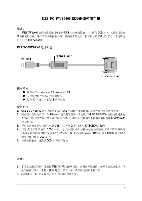
USB-PC-PWS6600编程电缆使用手册概述:USB-PWS6600编程电缆是通过电脑的USB口仿真成传统串口(俗称COM口),从而使用现有的各种编程软件、通信软件和监控软件等,转换盒上的发光二极管指示数据的收发状态,本电缆适用于HITECH PWS6600USB-PC-PWS6600电缆外观技术指标:●操作系统:Windows XP / Windows2000●支持编程软件版本:无限制版本●每台PC只支持一根USB编程电缆使用方法:1. USB-PC-PWS6600编程电缆需要安装USB驱动程序才能使用,驱动程序包含在所附光盘上。
2. 驱动程序安装完成后,在Windows的设备管理器中将出现USB-PC-PWS6600编程电缆对应的COM口号,只需在编程软件中选择该COM口号即可,其使用与9针串口编程电缆PC-PWS6600完全相同。
3.平时使用时先把电缆插入电脑USB口,再把25针口插入HITECH PWS66004.打开\资源管理器\查看COM口号, 方法为用鼠标单击\我的电脑\控制面板\管理工具\计算机管理\设备管理器\端口(COM和LPT) \ Prolific USB-to-Serial Comm(COMx)\ 这个COMx就是USB 编程电缆使用的COM口号5.打开编程软件, 设置好COM口号就可通信注意:1.不可在关闭编程软件前插拔USB-PC-PWS6600电缆,否则会不能通信。
如不小心已拔电缆,须关闭编程软件后,重复(使用方法)第3-5项。
或关闭电脑后重新开机。
2,通信长时间PLC仍无反应,须关闭电脑后重新开机。
USB-PC-PWS6600编程电缆驱动程序安装说明概述USB编程电缆是通过将电脑的USB口模拟成传统的串行口(通常为COM3),从而使编程软件通过USB-PC-PWS6600编程电缆与PWS6600系列进行通信。
功能●支持的操作系统Windows XP/ Windows2000●兼容USB V1.1 V2.0●波特率:300bps~1Mbps自动适应●每台PC只支持一根USB编程电缆系统要求请在使用USB编程电缆之前确认你的电脑是IBM PC兼容型并具备以下最低系统要求:●Intel兼容586DX4-100MHz中央处理器或更高●一个标准的USB接口(4-pin A型插座)驱动程序的安装驱动程序的安装非常简单,只需按提示进行即可,以Windows XP为例,按以下步骤进行:1、打开电脑主机,插入驱动程序光盘。


PWS6600/AP1600 的面板採用5.7" (320x240) 高解析度STN 的液晶顯示模組,並符合IP 65/NEMA 4的防水防塵設計等級。
其符合CE 的設計可滿足您高抗雜訊的應用需求,而設計簡潔美觀的面板,可靈活的配合機台設計運用,以達到機械整體的最佳價值效果。
PWS6600/AP1600 的軟體規劃使用ADP 6.0 以上版本,簡單好用且與其他機型相容,值得您的信賴。
當人機起動後,人機將會檢查硬體項目是否正常,其檢查的結果將顯示於LCD 的顯示區中,見下圖示。
人機自我測試顯示項目:圖 1. 人機開機自我測試前言如有不正常之項目,在其右邊將標示“Failed”,且在螢幕下方會出現“Error! Press screen to continue.”之訊息。
如觸碰螢幕,將繼續列出人機自我測試的項目。
如人機在下載資料中發生切斷電源或電腦中斷下載,重新啟動電源後,人機檢查硬體測試Firmware Checksum 或Application Checksum 項目的右方將會標示“Failed”。
這是正常現象,只須依正常方式再執行一次下載資料就可得到正確的測試結果。
設定 PWS6600/AP1600 的指撥開關 SW7=ON,當完成其自我測試,螢幕上將會顯示系統目錄如下:圖 2.PWS6600/AP1600 系統目錄以下表格簡述 PWS6600/AP1600 系統目錄之功能:1調整 Touch Panel 的方法:按人機螢幕左上角、右下角,遵循螢幕上路線描繪一遍,最後觸按中心的方塊,即完成人機調整 Touch Panel。
PWS6600/AP1600 配置六個功能按鈕,這六個功能按鈕包含一個 Menu 鍵及五個功能鍵– F1 ~ F5,見下圖。
如按 Menu 鍵將在螢幕上顯示一滑出式菜單,F1 ~ F5 鍵則可在 ADP 中設定常用的功能 (例如設 ON/OFF 按鈕、換畫面 … 等功能。

安装手册*本手册也涵盖了SEAKEEPER 7HD型号*2021年6月,修订版9安装手册产品:文档编号:修订版本:SEAKEEPER 9 / 7HD 90222 9SEAKEEPER 9 / 7HD安装手册2021年6月目录:第1节–机械安装和PC-120指南第2节–电气系统安装第3节–冷却系统安装第4节–启动第5节–安装检查事项清单和所需用品45310 ABELL HOUSE LN #350CALIFORNIA, MARYLAND, 20619, U.S.A电话:410-326-1590传真:410-326-1199电子邮件:*****************************底座底座1.1 预防措施•Seakeeper 9仅可通过提供的吊眼起吊(请参见第1.4节)。
•Seakeeper飞轮由精密轴承支撑。
拆除包装和吊起Seakeeper组件时,请勿掉落或使其受到机械震动,因为这样可能会使轴承受损。
•在搬运/安装Seakeeper组件时,请保护裸露的液压制动缸杆(见图1)不受刮擦或损坏,因为这可能会导致密封过早失效和机油泄漏。
•在搬运/安装Seakeeper组件时,不要让脱出Seakeeper外壳底部的电器配件接触任何表面或物体,因为这样可能会损坏这些配件,还可能会影响外壳的真空完整性。
•用心保护油漆表面,因为罩面受损可能会使安装好的Seakeeper的外观过早退化。
1.2 Seakeeper安装位置的选择选择Seakeeper的安装位置时应考虑以下理想特性:1. Seakeeper应安装在船的后部,以尽量减小高速运行或风浪大时因为船体/波浪的影响而产生的高加速度负荷。
如果唯一可能的Seakeeper安装位置在船中部,那么在完成设计之前安装者应让Seakeeper安装位置得到审查。
2. 需要为Seakeeper 9的定期维护和大修留出适当的维修设施用通道。
有关维修间隙要求,请参阅图2和90225 – Seakeeper 9/7HD螺栓安装细节。
安装手册*本手册还涉及 SEAKEEPER 20HD*1.1 预防措施•Seakeeper 只能使用所提供的吊眼进行吊装(请参阅第 1.4 节)。
•Seakeeper 飞轮由精密轴承支撑。
在打开包装和吊装Seakeeper 总成时,请确保不要掉落或引发机械震动,因为这可能会损坏轴承。
•在使用/安装Seakeeper 总成时,请保护外露的液压制动缸活塞杆(请参阅图1),保护其免遭刮伤或受到损坏,因为这可能会导致密封件过早失效,并会导致漏油。
•在使用/安装Seakeeper 总成时,不要让壳体底部外露的电器接头接触任何表面或物体,因为这可能会损坏这些接头,并可能会影响壳体的密封性。
•请小心保护面漆,因为面漆如果受损,则所安装 Seakeeper 的外观可能会过早失色。
1.2 选择 Seakeeper 的安装位置您在选择 Seakeeper 的安装位置时,应考虑以下所需特性:Seakeeper 应安装在船体后部。
操作时如果速度较高或风浪较大,则会产生船体/波浪冲击。
这种布置方式可将由此所产生的大加速负载降至最低。
Seakeeper 如果只可能安装在船体前部,则安装者在完成最终设计之前,应由 Seakeeper 对该安装位置进行评估。
•上方应有入口或有足够的间隙,以便以后能够拆卸/重新安装 Seakeeper 进行大修。
•Seakeeper 应安装在干燥的地方,尽量减小腐蚀的影响。
•留有间隙,可更换万向节轴上的万向节角度传感器(请参阅图2)。
•留有间隙,可加注/清空制动液压油(请参阅图2)。
•留有间隙,可加注水/乙二醇冷却回路(请参阅图2)。
•留有间隙,可更换制动液压缸(请参阅图2)。
安全Seakeeper 在进动时,万向节轴会产生很大的扭矩。
所提供的Seakeeper 盖板可防止人员或设备在Seakeeper 运行时与之发生接触。
您不得踩踏这些盖板,也不得在其顶部放置任何物品。
这些盖板在操作过程中,应始终放置到位。
貳.软件操作及练习前言:为了协助您很快的了解ADP3的规划操作,本章将详细介绍常用画面组成组件的基本范例,及几种典型组件的设计操作方法让初学者很快地就可以完成实际的画面编辑工作,并且逐步说明实际和P.L.C.联机之执行步骤及相关参数设定注意事项;并可立即和PLC联机操作。
而相关组件进阶应用之设计说明请洽各区经销商的人机应用课程介绍。
※本章说明乃针对PLC厂牌为S7-200 CPU214机型。
练习1、开启应用档1). 方法一:在档案栏的下拉窗体中选开新档案。
方法二:鼠标直接点取功能按钮行之开新档案图式按钮。
2). 出现如图2-1的对话框设定盒;您可输入新应用档批注名称“Myapplication”、选取PWS-人机接口的机型“PWS-700T”、及指定欲联机应用的PLC厂牌机型“Simatic S7-200 (via PPI)”。
图2-1 开新档案对话框设定盒一图2-2 开新档案对话框设定盒二3、当新应用文件被开启后,屏幕会出现图2-3 ADP3画面层程序窗口。
图2-3 ADP3程序窗口_应用文件层窗口练习2、认识画面组件可对应的PLC资料地址在ADP3开始规划画面组件前,设计者必须清楚了解可以使用的PLC资料地址的格式及范围;在ADP3软件中大部份均依照PLC本身原厂格式,所以您可以参考PLC原厂技术手册;下表所列为针对SIEMENS S7-200 CPU216:表1. 在ADP3软件规划可以使用的P.L.C.缓存器地址的格式及范围缓存器种类代号格式编号范围资料长度Remark Input Image IWn n=0-6 WordInput Image IDn n=0-4 Double WordOutput Image QWn n=0-6 WordOutput Image QDn n=0-4 Double WordInternal Bits MWnn nn=0-30 WordInternal Bits MDnn nn=0-28 Double WordSpecial Bits SMWnnn nnn=0-27 Word Read only Special Bits SMWnnn nnn=28-192 WordSpecial Bits SMDnnn nnn=28-190 Double WordData Area VWnnnn nnnn=0-5118 WordData Area VDnnnn nnnn=0-5116 Double WordSpecial S SWnn nn=0-30 WordSpecial S SDnn nn=0-28 Double WordTimer Tnnn nnn=0-255 WordCounter Cnnn nnn=0-255 WordAnalog input word AIWnn nn=0-30 Word Read only Analog output word AQWnn nn=0-30 Word Read only功能圖式按鈕行開新檔案圖式按鈕標題行存檔圖式按鈕開新畫面圖式按鈕呼叫畫面圖式按鈕呼叫舊檔圖式按鈕注意1:CPU-212 不能使用AIW, AQW, SW, SD注意2:PLC缓存器地址的范围须受限于P.L.C主机CPU的机型,应用时,请限制不可超过该CPU本身的最大值,否则会通讯失败。
海泰克触屏拨码开关定
义
SW1/SW2 保留
SW3 SW4
ON ON 使用者正常操作模式
ON OFF 执行者生产烧机程序
OFF ON 更新BIOS
OFF OFF 执行硬件测试
SW5 通讯参数设定
ON PWS 使用硬体的通讯参数与PLC 通讯
OFF PWS 使用ADP 的通讯与PLC 通讯
SW6 输入密码
ON 当PWS 开机自我检测后,要求输入密码
OFF 当PWS 开机检测后不要求输入密码
SW7 系统目录
ON 进入系统目录
OFF 不进入系统目录
SW8 预设者使用等级
OFF 如PWS 不要求密码( SW6 OFF )预设者等级=9
ON 如PWS 要求密码( SW6 OFF )预设者等级=1
SW9 COM1 规格设定
ON RS485 通讯
SW10 COM2 设定
ON RS485 通讯
OFF RS422 通讯
系统菜单指令
LINK 人机联机
F2-CONFG 通讯时间及通讯参数设定
F3-COPY 拷贝画面资料到另一台PWS6600/AP1600
F4-SET 调整人机Touch panel ' LCD 对比度及清除电池储备记忆F5-run 执行应用程序上载初始密码:222183600 或000000000。
PWS6600 MAEN849 2006-12EnglishBeijer Electronics, MAEN84921PWS6600 Installation1.1IntroductionPWS6600 is a Human Machine Interface (HMI) with a 10.4” TFT Liquid Crystal Display, and is water- and dust-resistant according to IP65/NEMA4.The HMI is CE-marked and meets your need to be highly transient-resistant while in operation.Also, its compact design makes connections with other machinery more flexible, thus achieving the optimal performance of your machines.ADP is used to design applications of the HMI; it is reliable, user-friendly and com-patible with many models.The latest released ADP Version 6.1 and above can be used to design applications for the HMI.1.2Safety PrecautionsBoth the installer, the owner, and the operator of this HMI must read and under-stand this installation manual.General–Only qualified personnel may install or operate the HMI.–The HMI must be installed according to the installation instructions.–The HMI is designed for stationary installation on a plane surface, where the fol-lowing conditions are fulfilled:• no high explosive risks • no strong magnetic fields • no direct sunlight• no large, sudden temperature changes–Never allow fluids, metal filings or wiring debris to enter any openings in the HMI. This may cause fire or electrical shock.–The HMI fulfills the requirements of article 4 of EMC directive 89/336/EEC.–Storing the HMI where the temperature is lower/higher thanrecommended in this manual can cause the LCD display liquid to congeal/become isotopic.–The LCD display liquid contains a powerful irritant. In case of skin contact, wash immediately with plenty of water. In case of eye contact, hold the eye open, flush with plenty of water and get medical attention.–The supplier is not responsible for modified, altered or reconstructed equipment.–Use only parts and accessories manufactured according to specifications of the supplier.–Peripheral equipment must be appropriate for the application and location.–The figures in this manual serves an illustrative purpose. Because of the many vari-ables associated with any particular installation, the supplier cannot assume re-sponsibility for actual use based on the figures.3Beijer Electronics, MAEN849–The supplier neither guarantees that the HMI is suitable for your particular appli-cation, nor assumes responsibility for your product design, installation or opera-tion.Power Source–The HMI is equipped with a 24 V DC input. Supply power other than 24 V DC ± 15% will severely damage the HMI. Thus, check the power supply supporting the DC power regularly.–To avoid electric shock, be sure the power cable is unplugged from the power out-let when connecting the cable to the HMI.Installation–Communication cables must be separated from the power cables for operational circuits. Use shielded cables or it may cause unpredictable problems.During Use–Emergency stop and other safety functions may not be controlled from the HMI.–Do not use force or sharp objects when touching the keys, display etc.Service and Maintenance–Only qualified personnel should carry out repairs.–Before carrying out any cleaning or maintenance operations, disconnect the equipment from the electrical supply.–Clean the display and surrounding front cover with a soft cloth and mild deter-gent.–Replacing the battery incorrectly may result in explosion. Only use batteries rec-ommended by the supplier.Dismantling and Scrapping–The HMI or parts thereof shall be recycled according to local regulations.–The following components contain substances that might be hazardous to health and the environment: lithium battery, electrolytic capacitor and display..1.3Package ContentsNote:Indicated loss of life, severe personal injury , or substantial property damage will result if proper precautions are not taken.Beijer Electronics, MAEN84941.4Mounting Procedure1.Cut out the control front panel to match the dimensions (mm) specified under the External and Cut-out dimensions chapter.2.Mount the HMI into the cut-out. Insert the fixtures to the holes on the unit and fasten the screws into the front panel. Do not tighten the screws with too much or uneven force, or it may cause deformation of the HMI.3.The HMI must be installed within an angle of 0° to 135° as shown above.1.5GroundingMake sure that the HMI works properly. To prevent it from radiating radio frequency noise, the HMI must be connected to earth ground.–Without grounding, the HMI may be severely affected by excess noise. Make sure that the grounding is done properly from the power connector at the rear side of the HMI. When power is connected, make sure that the wire is grounded.–Use a cable of at least 2 mm 2 (AWG 14) to ground the HMI. Ground resistance must be less than 100 Ohms (class3). Note that the ground cable must not be con-nected to the same ground point as the power circuit.1.6Power Supply and WiringThe HMI must use a power supply with 24 V DC and the power consumption is 20W.Steps to wire1.Unplug the power connector and unscrew the screws.2.Strip about 1 cm of insulation. Insert the wire all the way into the power connec-tor and then turn the screws tight.3.Plug in the connector to the power outlet of the HMI.Warning:T o avoid an electric shock, be sure to switch off the power before connecting the com-munication/download cable to the HMI.Note:Power connector is already plugged in the power outlet of the HMI when the package is first opened.1.7External and Cut-out Dimensions5Beijer Electronics, MAEN8491.8Description of PartsBeijer Electronics, MAEN84967Beijer Electronics, MAEN8491.9Product SpecificationsItemPWS6600C-N AP1600C-N PWS6600C-P AP1600C-P PWS6600C-S AP1600C-S PWS6600S-P AP1600S-N PWS6600S-P AP1600S-P PWS6600S-S AP1600S-SDisplay Type Color TFT LCD Mono STN LCD Display Color 256 colors 16 shades of blue Display size5.7”Display resolution 640 x 480, Number of 8 x 8 characters displayable 80 x 60Display adjust-mentVia touch panel & VR on the backBack light CCFT , Lifetime 75,000 hours @ 25 degrees Celsius CCFT , Lifetime 50,000 hours @ 25 degrees Celsius T ouch Screen AnalogKeypad1 Menu key and 5 user-defined Function keys (F1-F5)Keypad pressure and lifetime 350+-50 gf operating force, lifetime is over 1 million activations Input Power 24 V DC +-15%, less than 20W Flash ROM 4 MbRAM 512 K byte CPU32 bits RISC Battery backed memory 512 K byteRTCYES (rechargeable lithium battery)Data/Recipe 512 K byte -512 K byte -COM19-pin female connector , RS232 and RS485COM225-pin female connector , RS232,RS422 and RS485Multi-functional port26-pin connector to printer or 64 externel keys -26-pin connector to printer or 64 externel keys EthernetYES --Yes --Front Panel seal IP65 / NEMA 4Operating temperature 0° - 50°degrees Celsius Storage temperature-10° - 60° degrees CelsiusAmbient humidity 20-90% (non-condensing)Vibration endurance0.5 mm displacement, 10-55 Hz, 2 hours per X, Y , Z axis directions Shock endurance 10 G, 11 ms three times in each direction of X, Y , Z axes RF Emissions CISPR 22, Class A Electrostatic dischargeIEC61000-4-2RF Susceptibility IEC61000-4-3High Frequency TransientsIEC61000-4-4External dimen-sions195.0 x 145.0 x 59.1 mm Cut-out dimen-sions 185.8 x 135.8 mm Weight 0.81 kgCoolingNatural coolingNote:When using the HMI for the first time, remember to reset Real Time Clock (RTC).Beijer Electronics, MAEN84981.10Communication Ports–COM 1 is a 9-pin female connector used to connect a controller and the HMI via RS232 or RS485–COM 2 is a 25-pin female connector used to connect a controller and the HMI via RS232, RS422 or RS485Please make sure that the connection is in accordance with the setting of the dip switches. (For example, , RS485 with SW9 and SW10=ON).For illustration on the connection between the HMI and a controller, please consult the information on the controller.PIN FunctionPIN Function1RS485+1N/A2RS232 RXD 2RS232 TXD 3RS232 TXD 3RS232 RXD4N/A4RS232RTS 5Signal ground 5RS232 CTS 6RS485-6N/A7RS232 RTS 7Signal ground8RS232 CTS8Optional +5 V @ 100mA output 9Optional +5 V @ 100mA output9N/A 10N/A 11N/A12RS422 CTS+13RS422 CTS-14RS422 TX+ (RS485+)15RS422 TX- (RS485-)PIN Function16RS422 RX+17RS422 RX-1RS422+ (RS485 TX+)18N/A 2RS422 CTS+19N/A 3RS422 CTS-20N/A 4RS422 RX+21N/A 5Signal ground22N/A6RS422- (RS485 TX-)23RS422 RTS+7RS422 RTS+24RS422 RTS-8RS422 RTS-25N/A1.11Dip SwitchesDip Switches FunctionSW 1ReservedSW 2ReservedSW 3SW 4Operation ModeON ON Runs user applicationON OFF Runs burn-in test programOFF ON Updates BIOSOFF OFF Runs bench test programSW 5Communication ParametersON The HMI uses parameters defined on the Configuration Screen forcontroller communicationsOFF The HMI uses parameters defined in ADP for controller communica-tionsSW 6PasswordON The HMI asks the operator to enter a password after power-on self-testOFF No password is required to start the HMISW 7System MenuON The HMI displays System MenuOFF The HMI runs user application without displaying System MenuSW 8Default user levelON The default user level is set to 1 if the HMI requires no password tostart its operationOFF The default user level is set to 9 if the HMI requires no password tostart its operationSW 9COM 1 PortON For RS485 this switch has to be set ONSW 10COM 2 PortON For RS485 this switch has to be set ONOFF For RS422 this switch has to be set OFF9Beijer Electronics, MAEN849Beijer Electronics, MAEN849102PWS6600 Operation2.1Self TestOnce the HMI is turned on, it will automatically execute a self-test to check its hard-ware. The result of a self-test is displayed on the LCD. See below for items to check in a self-test:If any of tests does not pass the self-test, it will be noted with “Failed” next to the test item. Additionally, the message “Error! Press screen to continue” will be displayed at the bottom of the screen.If the power to the HMI or the PC was interrupted while downloading, Firmware checksum or Application checksum will not pass the self-test, indicated by “Failed” in the self-test results after power is restored. If this happens, the user can simply fol-low the download procedure to re-download the application or data. After down-loading again, all items should pass the self-test.2.2System MenuSet the dip switch SW7=ON. After the self-test, the system menu of the HMI is dis-played on the screen:The functions of the commands are briefly explained below:System Menu FunctionLinkThe HMI is connected.F2 - ConfgSets up the internal time clock and communication parameters in the HMI. All the settings has to be made for the HMI to work e , , and to move to desired field; + and - to set the value of the field.F3 - Copy Copies application data to another HMI.F4 - Set Calibrates the touch screen, adjusts LCD contrast and clears RAM data.F5 - RunRuns the application.11Beijer Electronics, MAEN8492.3KeypadThe eight keys on the HMI include one menu key and seven functional keys (F1 -F5). Press the menu key to slide out the innovative slide-out menu. For further details on the slide-out menu please see the ADP User’s ManualWhen a key is pressed, the HMI will make a “beep” sound to signal that a command is pressed. (The default setting is a 200 ms beep, and can be configured.)2.4Bench and Function TestsSet the dip switches SW3 and SW4=OFF to be able to run the bench and function tests for the HMI. T urn on the HMI and the following screen will be displayed.The bench test performs an overall hardware test and the function test lets the user select which item to be tested.2.5Setting Communication Parameters There are two ways to configure working parameters; to set parameters in the HMI or in ADP .To set parameters in the HMI, select F2 - Confg in the system menu.To set parameters in ADP , select Application / Workstation Setup . Then select the Connection tab to set communication parameters.Note:The bench test will clear the application data of the HMI.Note:Remember to set the dip switch SW5=ON if parameters are set in the HMINote:Remember to set the dip switch SW5=OFFif parameters are set in ADPBeijer Electronics, MAEN849122.6Downloading an ApplicationConnect the RS232 port on the PC to the COM1 port on the HMI using a WPC-P8-42 cable. The connection can also be made according to the illustration below.Set the dip switch SW7 = ON . After the self-test, the system menu will be displayed on the screen and the HMI is ready to download the application.Start ADP and open the application file to be downloaded. Make sure that the com-munication parameters are correctly configured. Also remember to compile the file before downloading it. The file has to be compiled every time a change has been made in the file before downloading it.Then select Application/Download Firmware and then Application in ADP if it is a first time to download the application to the HMI; otherwise, select Application/Download Application . The following appears on the screen while the HMI is downloading:2.7Uploading an ApplicationAn application can also be uploaded from the HMI to the PC. Thus, a user can save an application as a *.V6F file in ADP for future use.Make sure that the HMI and the PC are connected according to section “Download-ing an Application”. Set the dip switch SW7 = ON . After the self-test, the system menu will be displayed on the screen and the HMI is ready to upload the application. Also make sure that communication parameters are correctly configured. Select File/Upload Application in ADP and the Save As dialog box will appear on the screen. Enter the name of a firmware file (*.AF6) to save. Click Save . Then the HMI will prompt for a password: enter the password set in ADP from Application/Worksta-tion Setup . Once the correct password is entered, the HMI starts to upload the ap-plication to the PC. For information about setting a password, please see section “Setting a Password“.Warning:T o avoid an electronic shock, be sure to switch off the power before connecting the download cable to the HMI.T o avoid an electric shock, be sure to switch off the power before connecting the com-munication cable to the HMI.13Beijer Electronics, MAEN849While the HMI is uploading, the following is displayed:After uploading, select File/Reconstruct Source in ADP to display the Open dialog. Open the uploaded application file (*.C64 or *.AA6). The application screen will be displayed on the PC monitor. Finally, select File/Save As to save the application as a *.V6F file. Thus a source file can serve the purposes of maintenance and modifica-tion.2.8Uploading / Downloading a RecipeSet the dip switch SW7 = ON . After the self-test, the system menu will be displayed on the screen and the HMI is ready to upload/download a recipe.Uploading a RecipeSelect File/Upload Recipes in ADP and the Save As dialog box will appear on the screen. Enter the name of a recipe file (*.RCP) to save. Click Save . While the HMI is uploading the recipe, Uploading recipes is displayed on the screen.Downloading a RecipeOpen an application file with the recipe to be downloaded in ADP . Select File/Download Recipes to display the Open dialog. Enter the name of the recipe file (*.RCP) and click Open . While the HMI is downloading the recipe, Downloading recipes is displayed on the screen:After the download is finished, select F5 - Run to run the application.Remember to define the length and the number of recipes in the application. Also remember to upload the format of recipes from the HMIbefore starting to edit a new set of recipe data in the PC.For further information about creating/editing recipes, please see the corresponding chapter in the ADP User’s Manual.Note:When using the HMI for the first time, reset the real time clock (RTC).Beijer Electronics, MAEN849142.9Copying an ApplicationTo copy an application from one HMI to another, select F3 - Copy from the system menu. Set the dip switch SW7 = ON and connect the two HMIs with a download cable. After the self-test, the system menu will be displayed on the screen.Select F3 - Copy in the system menu from the HMI with the application to be cop-ied. The HMI will prompt for a password: enter the password set in ADP from Ap-plication/Workstation Setup . Once the correct password is entered, the HMI will start to copy the application between the two HMIs. The following appears on the screens during the copying:2.10Setting a PasswordScenario 1: Requiring a password to start the HMIIf the dip switch SW6 = ON , the user needs to enter a password to start the HMI. For this purpose, the designer can use the object Action Button in ADP to create a button which displays the password table on the HMI display. A user with the right to access the table can register passwords and user levels in the table. In the illustra-tion below, the TBL-button is an action button used to display the password table. When the button is selected the password table is displayed on the screen for a user with the right to access the table. Touch the password to highlight an area for entering a value.In the illustration above, the TBL-button is an action button used to display the pass-word table. When the button is selected the password table is displayed on the screen for a user with the right to access the table. Touch the password to highlight an area for entering a value.How to configure an Action Button is described in the ADP User’s Manual.After registering passwords and user levels, set the dip switch SW6 = ON (i.e. pass-word required). Restart the HMI and after the self-test the user will be prompted to enter a password in order to run the HMI. The HMI will determine the user level from the entered password. For instance, if the level of the password entered by the user is 2, then the HMI will set the user level to 2. User level 1 has the highest priv-ilege and User level 9 has the lowest.Note:If it is the first time to copy, please remember to run the application.Note:Only users of User Level 1 has the right of access to the password table.15Beijer Electronics, MAEN849Scenario 2: Re-entering a passwordThe object Action Button in ADP also allows the designer to create a button which asks the user to re-enter a password. For example, by pressing the PSW -button the password keypad will be displayed to prompt the user to enter a password. After en-tering the password, the HMI will update the user level according to the most recent password which has been entered. Therefore, this button can be applied to raise or drop one’s privileges while the HMI is in operation.How to configure an Action Button is described in the ADP User’s Manual.Scenario 3: Password-protecting a button in the HMIThe ADP can create a button which is protected by a password for execution. For example, a Goto Screen button can be designed with a high level of security; which means that a password with a high level of privilege is required in order to open the other screen. As the button is selected and the current user has a lower privilege than has been set for the button, the HMI will prompt the user for a password. The user will need a password with at least the level of privilege that has been set for the but-ton. This function can restrict users to access to certain parts of the application.Scenario 4: Requiring a password to copy or upload application When selecting F3 - Copy in the system menu or File/Upload Application in ADP , the HMI will prompt for a password. The user will need to enter the correct password to copy an application from one HMI to another. Note that setting this password is different from the passwords set in Scenarios 1-3. To set this password, select Appli-cation/Workstation Setup in ADP . Under the Password tab, the project designer isable to set the password.Hitech Electronics Corp.4F, No. 501-15, Chung-Cheng Road Shin-Tien, T aipei Shien, Taiwan, R.O.C. Telephone: +886-2-2218-3600 Telefax: +886-2-2218-9547。