Chem.Soc.Rev.,2012,41,7938–Defect-related luminescent materials
- 格式:pdf
- 大小:4.94 MB
- 文档页数:24
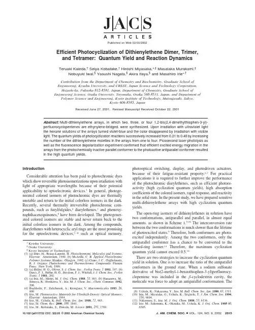
Efficient Photocyclization of Dithienylethene Dimer,Trimer, and Tetramer:Quantum Yield and Reaction DynamicsTeruaki Kaieda,†Seiya Kobatake,†Hiroshi Miyasaka,*,‡Masataka Murakami,‡Nobuyuki Iwai,§Yasushi Nagata,§Akira Itaya,§and Masahiro Irie*,†Contribution from the Department of Chemistry and Biochemistry,Graduate School ofEngineering,Kyushu Uni V ersity,and CREST,Japan Science and Technology Corporation,Higashi-ku,Fukuoka812-8581,Japan,Department of Chemistry,Graduate School of Engineering Science,Osaka Uni V ersity,Toyonaka,Osaka560-8531,Japan,and Department of Polymer Science and Engineering,Kyoto Institute of Technology,Matsugasaki,Sakyo,Kyoto606-8585,JapanReceived June27,2001.Revised Manuscript Received October22,2001Abstract:Multi-dithienylethene arrays,in which two,three,or four1,2-bis(2,4-dimethylthiophen-3-yl)-perfluorocyclopentenes are ethynylene-bridged,were synthesized.Upon irradiation with ultraviolet light the hexane solutions of the arrays turned violet-blue and the color disappeared by irradiation with visible light.The quantum yields of photocyclization reactions successively increased from0.21to0.40by increasing the number of the dithienylethene moieties in the arrays from one to four.Picosecond laser photolysis as well as the fluorescence depolarization experiment confirmed that efficient excited energy migration in the arrays from the photochemically inactive parallel conformer to the photoactive antiparallel conformer resulted in the high quantum yields.IntroductionConsiderable attention has been paid to photochromic dyes which show reversible photoisomerizations upon irradiation with light of appropriate wavelengths because of their potential applicability to optoelectronic devices.1In general,photoge-nerated colored isomers of photochromic dyes are thermally unstable and return to the initial colorless isomers in the dark. Recently,several thermally irreversible photochromic com-pounds,such as furylfulgides,2diarylethenes,3and phenoxy-naphthacenequinones,4have been developed.The photogener-ated colored isomers are stable and never return back to the initial colorless isomers in the dark.Among the compounds, diarylethenes with heterocyclic aryl rings are the most promising for the optoelectronic devices,5-8such as optical memory,photooptical switching,display,and photodriven actuators, because of their fatigue-resistant property.6,7For practical applications it is required to further improve the performance of the photochromic diarylethenes,such as efficient photore-activity(high cyclization quantum yields),high absorption coefficients of the colored isomers,rapid response,and reactivity in the solid state.In the present study,we have prepared sensitive multi-dithienylethene arrays with high cyclization quantum yields.The open-ring isomers of dithienylethenes in solution have two conformations,antiparallel and parallel,in almost equal amounts,as shown in Scheme1.9,10The interconversion rate between the two conformations is much slower than the lifetime of photoexcited states.9Therefore,both conformers are photo-excited independently.Among the two conformers,only the antiparallel conformer has a chance to be converted to the closed-ring isomer.11Therefore,the maximum cyclization quantum yield cannot exceed0.5.12There are two strategies to increase the cyclization quantum yield in solution.One is to increase the ratio of the antiparallel conformers in the ground state.When a sodium sulfonate derivative of bis(2-methyl-1-benzothiophen-3-yl)perfluorocy-clopentene was included in the -cyclodextrin cavity,the molecule was force to adopt an antiparallel conformation.The†Kyushu University.‡Osaka University.§Kyoto Institute of Technology.(1)(a)Du¨rr,H.;Bouas-Laurent,H.Photochromism,Molecules and Systems;Elsevier:Amsterdam,1990.(b)McArdle,C.B.Applied Photochromic Polymer Systems;Blankie:Glasgow,1992.(c)Crano,J.C.;Guglielmetti, anic Photochromic and Thermochromic Compounds;Plenum Press:New York,1999.(2)(a)Heller,H.G.;Oliver,S.J.Chem.Soc.,Perkin Trans.11981,197.(b)Darcy,P.J.;Heller,H.G.;Strydom,P.J.;Whittall,J.J.Chem.Soc.,Perkin Trans.11981,202.(3)(a)Irie,M.;Mohri,.Chem.1988,53,803.(b)Hanazawa,M.;Sumiya,R.;Horikawa,Y.;Irie,M.J.Chem.Soc.,mun.1992, 206.(4)Buchholtz,F.;Zelichenok,A.;Krongauz,V.Macromolecules1993,26,906(5)Irie,M.Photoreacti V e Materials for Ultrahigh-Density Optical Memory;Elsevier:Amsterdam,1994.(6)Irie,M.;Uchida,K.Bull.Chem.Soc.Jpn.1998,71,985.(7)Irie,M.Chem.Re V.2000,100,1685.(8)Irie,M.;Kobatake,S.;Horichi,M.Science2001,291,1769.(9)Uchida,K.;Nakayama,Y.;Irie,M.Bull.Chem.Soc.Jpn.1990,63,1311.(10)Irie,M.;Miyatake,O.;Uchida,K.;Eriguchi,T.J.Am.Chem.Soc.1994,116,9894.(11)Nakamura,S.;Irie,.Chem.1988,53,6136.(12)Irie,M.;Sakemura,K.;Okinaka,M.;Uchida,.Chem.199560,8305.Published on Web02/09/200210.1021/ja0115722CCC:$22.00©2002American Chemical Society J.AM.CHEM.SOC.9VOL.124,NO.9,20022015cyclization quantum yield was found to increase from 0.32to 0.49.13Zerbi et al.14also ascribed the high cyclization quantum yield of a polymer having dithienylethenes in the main chain to the enforced antiparallel conformation of the dithienylethene moieties in the ground state.The other strategy is to increase the ratio of antiparallel conformers in the photoexcited state.When photoexcited energy can be transferred from the photo-chemically inactive parallel conformation unit to the photoactive antiparallel one,the quantum yield is expected to increase.Such energy transfer is probable in dithienylethene dimer,trimer,or tetramer,in which the dithienylethene moieties are ethynylene-bridged.15-18Recently,Branda et al .19reported limited photo-chromic reactivity of dithienylethene dimers,in which two dithienylethene moieties are connected by a single bond.When N dithienylperfluorocyclopentene moieties are con-nected with conjugated bonds,the system has 2N conformations by a combination of parallel and antiparallel conformations.Among the 2N conformations,only one conformation,in which all dithienylethene moieties are in the parallel conformation,cannot cyclize to the closed-ring isomer by photoirradiation,while (2N -1)other conformations can undergo the photocy-clization reaction by transferring the photoexcited energy to the antiparallel conformation unit.Figure 1lists all conformations of the monomer,dimer,trimer,and tetramer systems.From the list it is inferred that the ratio of photoactive systems increases from 0.5to 0.94by increasing the number of dithienylethene moieties in the arrays from one to four,resulting in high quantum yields.In this work,the dimer,trimer,and tetramer in Scheme 2were synthesized and the quantum yields and the mechanism of the cyclization reactions were studied by irradia-tion with continuous as well as picosecond laser pulse light.Results and DiscussionPhotochromism of Dimer in Hexane.Figure 2shows the absorption spectral change of the dimer in hexane by photoir-radiation.Upon irradiation with 320nm light,the colorless solution of the open-ring form dimer with the absorptionmaximum at 320nm ( ,2.3×104M -1cm -1)turned violet,in which characteristic absorption maxima were observed at 365and 584nm.The violet color indicates formation of the closed-ring isomer.6Upon visible (λ>540nm)light irradiation,the violet color disappeared indicating return to the initial open-ring isomer.The coloration/decoloration cycle could be repeated more than 10times and a clear isosbestic point was observed at 338nm even after 10cycles.The photoirradiated sample was analyzed with high perfor-mance liquid chromatography (HPLC,silica gel column,Wa-kosil 5SIL,eluent hexane/ethyl acetate (96:4)).When monitored at the isosbestic point of 338nm,two peaks were observed.When the monitoring wavelength was shifted to 584nm,at which wavelength only the closed-ring form absorbs,only one peak was observed in the HPLC chart.This indicates that only one closed-ring isomer was produced by UV irradiation.Even after prolonged irradiation any other photoproduct was not(13)(a)Takeshita,M.;Choi,C.N.;Irie,mun.1997,2265.(b)Takeshita,M.;Kato,N.;Kawauchi,S.;Imase,T.;Watanabe,J.;Irie,.Chem.1998,63,9306.(14)Stellacci,F.;Bertarelli,C.;Toscano,F.;Gallazzi,M.C.;Zolti,G.;Zerbi,G.Ad V .Mater.1999,11,292.(15)Hsiao,J.-S.;Krueger,B.P.;Wagner,R.W.;Johnson,T.E.;Delaney,J.K.;Mauzerall,D.C.;Fleming,G.R.;Lindsey,J.S.;Bocian,D.F.;Donohoe,R.J.J.Am.Chem.Soc.1996,118,11181.(16)Yang,S.I.;Lammi,R.K.;Seth,J.;Riggs,J.A.;Arai,T.;Kim,D.;Bocian,D.F.;Holten,D.;Lindsey,J.S.J.Phys.Chem.B 1998,102,9426.(17)Li,J.;Ambroise A.;Yang,S.R.;Diers,J.R.;Seth,J.;Wack,C.R.;Bocian,D.F.;Holten,D.;Lindsey,J.S.J.Am.Chem.Soc.1999,121,8927.(18)Lammi,R.K.;Ambroise A.;Balasubramanian,T.;Wagner,R.W.;Bocian,D.F.;Holten,D.;Lindsey,J.S.J.Am.Chem.Soc.2000,122,7579.(19)Peters,A.;Branda,N.R.Ad V .Mater.Opt.Electron.2000,10,245.Scheme 1.Photochromism ofDithienyletheneFigure 1.Conformations of monomer,dimer,trimer,and tetramermolecules.Figure 2.Absorption spectral change of the dimer in hexane upon irradiation with 320nm light:(s )before photoirradiation and (---)after UV-light irradiation for 11min.The fluorescence spectrum of the (O -O)dimer in hexane was also shown (---).Scheme 2.Structure of Monomer,Dimer,Trimer,andTetramerA R T I C L E SKaieda et al.2016J.AM.CHEM.SOC.9VOL.124,NO.9,2002detected.The absence of the isomer having two closed-ring forms in the photoirradiated dimer agrees to the result observed in the dimers reported by Branda et al .19The colored isomer was collected and the structure was analyzed by 1H NMR spectroscopy.The methyl protons of the colored dimer showed seven signals,as shown in Figure 3a.In the NMR spectrum there existed a characteristic signal at 2.00ppm assigned to the methyl protons of the closed-ring form and a characteristic signal at 2.04ppm assigned to the methyl protons of the open-ring form.20The ratio of the two signals was 1:1,which means that the colored isomer is an (O -C)dimer having an open-ring form (O)and a closed-ring form (C).The isomer in which both dithienylethenes are in the closed-ring form (C -C)was not detected.To search for the reason the isomer having two closed-ring forms (C -C)was not produced,fluorescence spectra of the initial open-ring form (O -O)dimer and the photogenerated (O -C)dimer were measured in hexane.When excited at 320nm,the (O -O)dimer gave fluorescence at 440nm,while the (O -C)dimer did not give fluorescence.As can be seen from Figure 2,there is an overlap of the fluorescence of the (O -O)dimer and the absorption of the (O -C)dimer.The overlap suggests that the intramolecular energy transfer is possible from the excited open-ring unit to the closed-ring unit.In other words,when the (O -C)dimer is excited with UV light,the excited energy of the open-ring form unit is efficiently transferred to the closed-ring form unit in the same molecule,as shown inScheme 3.Therefore,the cyclization reaction of the remaining open-ring form unit cannot take place.The efficient intramo-lecular energy transfer process will be discussed in detail in later sections,using the fluorescence depolarization experiment and picosecond laser photolysis.Photochromism of Trimer in Hexane.Figure 4shows the absorption spectral change of the trimer by UV irradiation in hexane.Upon irradiation with 320nm light,the colorless solution of all open-ring form (O -O -O)trimer with the absorption maximum at 325nm ( ,4.6×104M -1cm -1)turned blue,in which characteristic absorption maxima were observed at 365and 620nm.Upon visible (λ>540nm)light irradiation,the blue color disappeared.The HPLC chromatogram (monitoring wavelength 342nm)of the solution after UV irradiation is shown in Figure 5.Four peaks were observed.When the monitoring wavelength was changed to 600nm where the open-ring form unit has no absorption,three peaks except the second peak were observed,indicating that there existed three kinds of closed-ring form isomers.The four peaks were isolated and their structures were determined by UV -vis absorption spectral measurement and 1H NMR spectroscopy.The first peak trimer had the absorption maximum at 635nm ( ,2.4×104M -1cm -1).The third and fourth peak trimers had the maxima at 584nm.These colored isomers converted(20)In the NMR spectrum of the monomer,the methyl signals of the open-ring isomer were observed at 2.04and 2.29ppm,while they shifted to 2.00and 2.14ppm in the closed-ringisomer.Figure 3.1H NMR methyl signals of the (O -C)dimer (a)and the (O -C -O)trimer(b).Figure 4.Absorption spectral change of the trimer in hexane upon irradiation with 320nm light:(s )before photoirradiation and (---)after UV-light irradiation for 11min.Figure 5.HPLC chromatogram of the trimer irradiated with 320nm for 11min in hexane.A UV detector was used for monitoring at 342nm.The column was silica gel (Wakosil 5SIL)and the eluent was hexane/ethyl acetate (98:2).Scheme 3.Intramolecular Energy Transfer in the ExcitedStatePhotocyclization of Dithienylethene Di-,Tri-,and Tetramers A R T I C L E SJ.AM.CHEM.SOC.9VOL.124,NO.9,20022017to the open-ring form trimer by irradiation with visible light (λ>540nm).The absorption maxima suggest that the first peak trimer has the closed-ring form in the middle,while the third and fourth peak trimers have the closed-ring form unit(s)at the end,because the absorption maximum of 584nm was the same as the maximum of the (O -C)dimer.The structures were further examined by 1H NMR measurement.The methyl protons of the second peak trimer were observed at 2.04,2.11,and 2.29ppm,which are assigned to an all open-ring form (O -O -O)trimer.The methyl protons of the first peak trimer showed five signals,as shown in Figure 3b.In the NMR spectrum there was no characteristic signal at 2.00ppm,which is assigned to the methyl protons of the terminal closed-ring form.This result indicates that the product does not contain the terminal closed-ring form.Thus,the first peak is the (O -C -O)trimer having one closed-ring form unit at the middle.The methyl protons of the third peak trimer showed six peaks.In the NMR spectrum there existed a characteristic signal at 2.00ppm assigned to the terminal closed-ring form and a characteristic signal at 2.04ppm assigned to the terminal open-ring form.The ratio of the two signals was 1:1,which means the colored isomer is the (O -O -C)trimer having one closed-ring form at the one end.The absorption coefficient of the fourth peak trimer (584nm; ,2.9×104M -1cm -1)was twice as large as that of the third peak trimer (584nm; ,1.4×104M -1cm -1),which is the same as that of the (O -C)dimer.This indicates that the peak is due to the (C -O -C)trimer having two closed-ring form units at both ends.The fourth peak is not due to the (O -C -C)trimer,because the absorption maxima was observed at 584nm (assigned to the terminal closed-ring form),not at 635nm (assigned to the middle closed-ring form),and the characteristic signal at 2.04ppm assigned to the terminal open-ring form was not observed.Any isomer in which neighboring two dithienylethene units are converted to the closed-ring forms was not detected.The time-course of formation of the three isomers (O -C -O,O -O -C,C -O -C)was measured by HPLC,as shown in Figure 6.Upon UV-light irradiation,the amount of all open-ring form (O -O -O)trimer decreased.At the same time the amount of two trimers,O -C -O and C -O -O,having closed-ring form units increased.After 11min of photoirradiation,the ratio of (C -O -C),(O -C -O),and (O -O -C)isomers was 3:54:39.The amount of (C -O -C)trimer having two closed-ring form units at both ends increased gradually.The rate for formation of the (O -C -O)trimer having one closed-ring formunit in the middle was faster than that of the (O -O -C)trimer having one closed-ring form unit at the end.Photochromism of Tetramer in Hexane.The absorption spectral change of the tetramer in hexane is shown in Figure 7.Upon irradiation with 320nm light,the colorless solution of the open-ring form tetramer with the absorption maximum at 325nm ( ,6.9×104M -1cm -1)turned greenish-blue,in which characteristic absorption maxima were observed at 354and 625nm.Upon visible (λ>540nm)light irradiation,the greenish-blue color disappeared.Figure 8shows the HPLC chromatogram (monitoring wave-length 346nm)of the solution after UV irradiation.Five peaks were observed.When the monitoring wavelength was changed to 600nm,where the open-ring form has no absorption,four peaks except the third peak were observed.These four peaks were ascribed to the closed-ring form isomers.The first peak tetramer had the absorption maximum at 635nm,while the maximum shifted to 620nm in the second peak tetramer.The fourth and fifth peaks had the absorption maximum at 584nm.These colored compounds converted to the open-ring form isomer by irradiation with visible light (λ>540nm).These colored and colorless isomers were isolated and their structures were determined by 1H NMR and absorption spectroscopy.The methyl protons of the third peak tetramer were observed at 2.04,2.11,and 2.29ppm,which are identical to those of the open-ring form isomer.The methyl protons of the first peak tetramer showed six signals,in which there was no characteristic signal at 2.00ppm.This indicates that the first peak is due to the tetramer having no closed-ring form unit at the end and having one inner closed-ring form unit.The methyl protonsofFigure 6.The change in the content of the isomers of the trimer upon irradiation with 320nm:the (O -O -O)trimer (O ),the (O -C -O)trimer (0),the (O -O -C)trimer ()),and the (C -O -C)trimer (×).Figure 7.Absorption spectral change of the tetramer in hexane upon irradiation with 320nm light:(s )before photoirradiation and (---)after UV-light irradiation for 8min.Figure 8.HPLC chromatogram of the tetramer irradiated with 320nm in hexane.A UV detector was used for monitoring at 346nm.The column was silica gel (Wakosil 5SIL)and the eluent was hexane/ethyl acetate (96:4).A R T I C L E S Kaieda et al.2018J.AM.CHEM.SOC.9VOL.124,NO.9,2002the second peak tetramer showed six peaks.In the spectrum there existed characteristic signals at 2.00and 2.04ppm assigned to the terminal closed-ring and open-ring forms,respectively.The peak intensity of a characteristic signal at 2.17ppm,which is assigned to the methyl protons at the quantarnary carbons in the closed-ring form units,indicates that two closed-ring form units are included in the molecule.This means that the colored isomer is the (O -C -O -C)tetramer having one terminal closed-ring form unit and one inner closed-ring form unit.This peak is not due to the (O -O -C -C)tetramer,because the signal at 2.33ppm was 3times larger than the signal at 2.29ppm.The fourth and fifth peaks had the same absorption maximum at 584nm.The absorption coefficient of the fifth peak ( ,2.8×104M -1cm -1)was twice as large as that of the fourth peak ( ,1.4×104M -1cm -1)at 584nm,indicating that the fourth peak is due to the (O -O -O -C)tetramer having one closed-ring form at the end.The fifth peak is the (C -O -O -C)tetramer having two closed-ring form units at both ends.Even in the tetramer any isomer,in which both neighboring dithienylethene units are converted to the closed-ring form,was not detected.The time-course of formation of the four isomers,(O -C -O -O),(O -O -O -C),(O -C -O -C),and (C -O -O -C),was measured by HPLC,as shown in Figure 9.Upon UV irradiation,the amount of all open-ring tetramer immediately decreased and at the same time the amount of two closed-ring isomers,(O -C -O -O)and (O -O -O -C),increased.The amount of the (C -O -O -C)tetramer having two closed-ring form units at both ends and the (O -C -O -C)tetramer having both inner and terminal closed-ring form units increased gradually.The rate of formation of the (O -C -O -O)tetramer having an inner closed-ring form unit was faster than that of the (O -O -O -C)tetramer having a terminal closed-ring form unit.Quantum Yields of Dimer,Trimer,and Tetramer.The cyclization quantum yields of dimer,trimer,and tetramer were measured at room temperature.The quantum yield measurement was carried out as follows.The dimer and the trimer were dissolved in hexane and the solutions were irradiated with ultraviolet light (λ)340nm).Cyclohexane was used as the solvent for the tetramer because of its low solubility in hexane.A 500W xenon lamp was used as the light source and the irradiation wavelength (λ)340nm)was isolated by passing the light through a monochromator.In the case of the monomer and the dimer the rate of cyclization reaction was followed by measuring the absorption increase at 534nm ( ,5.0×103M -1cm -1)21and 584nm ( ,1.4×104M -1cm -1),respectively.Inthe case of the trimer and the tetramer the irradiated hexane or cyclohexane solutions were passed through HPLC and the ratio change of each product upon irradiation was analyzed by setting the monitoring wavelength to the quasi-isosbestic point.The absorption increase at 584and 635nm was also followed to confirm the accuracy of the quantum yield determination.The light intensity was monitored by a photometer,which was cali-brated by the photoreaction of furylfulgide in hexane solution.The quantum yield measurement was carried out three times for each multi-dithienylethene arrays and the average values were adopted as the quantum yields.The error of the relative quantum yields among the oligomers was less than (5%,while the error of absolute values was on the order of (10%.The quantum yield of the open-ring form (O -O)dimer to the (O -C)dimer was determined to be 0.31.The yields of the trimer from the all open-ring form (O -O -O)isomer to the (O -C -O)isomer having one closed-ring form unit at the middle and the (O -O -C)isomer having one closed-ring form unit at the end were 0.20and 0.16,respectively.The total cyclization yield of the trimer was 0.36.The cyclization quantum yields of the tetramer from the all open-ring form (O -O -O -O)isomer to the (O -C -O -O)isomer having one inner closed-ring form unit and the (O -O -O -C)isomer having one terminal closed-ring form unit were determined to be 0.30and 0.10,respectively.The total cyclization quantum yield was 0.40.The photocyclization quantum yields increased by increasing the number of dithienylethene moieties in the arrays.The increase in the quantum yields is attributed to the intramolecular energy migration from the photochemically inactive parallel conforma-tion unit to the photoactive one,as described in the introductory section.Fluorescence Depolarization.To confirm the intramolecular energy migration in the arrays,depolarization of fluorescence was measured in a 2-methyltetrahydrofuran rigid glass at 77K.An excitation wavelength of 320nm was selected.Dithie-nylethenes undergo photochromic reactions even in the solid state at low temperature.22Fluorescence spectra of the dimer,the trimer and the tetramer gave a similar emission at 440nm,while the emission of the monomer was observed at 420nm.The fluorescence polarization values (p )(I ||-I ⊥)/(I ||+I ⊥))were determined to be 0.51(monomer),0.23(dimer),0.17(trimer),and 0.14(tetramer),respectively.For the monomer,the polarization of the fluorescence directly correlates with the direction of the polarized excitation light.In the case of the multi-dithienylethene arrays,depolarization took place.The p values decreased by increasing the number of the dithienylethene moieties in the arrays.This result clearly indicates that the excited energy migrates in the arrays.23Reaction Dynamics.To reveal the dynamics of the excited energy migration,a laser photolysis experiment was carried out with use of a picosecond laser pulse.Figure 10a shows the time-resolved transient absorption spectra of the dimer in a hexane solution excited with a picosecond 355nm laser pulse.A broad absorption spectrum with maxima around 490and 750nm appeared within the time resolution of the apparatus,followed(21)Uchida,K.;Irie,M.Chem.Lett.1995,969.(22)(a)Kobatake,S.;Yamada,T.;Uchida,K.;Kato,N.;Irie,M.J.Am.Chem.Soc.1999,121,2380.(b)Irie,M.;Lifka,T.;Kobatake,S.;Kato,N.J.Am.Chem.Soc.2000,122,4871.(23)(a)David,C.;Baeyens-Volant,D.;Geuskens,G.Eur.Polym.J.1976,12,71.(b)David,C.;Putman-de Lavareille,N.;Geuskens,G.Eur.Polym.J.1977,13,15.Figure 9.The change in the content of the isomers of the tetramer upon irradiation with 320nm:the (O -O -O -O)tetramer (O ),the (O -O -C -O)tetramer (0),the (O -O -O -C)tetramer ()),the (O -C -O -C)tetramer (×),and the (C -O -O -C)tetramer (4).Photocyclization of Dithienylethene Di-,Tri-,and Tetramers A R T I C L E SJ.AM.CHEM.SOC.9VOL.124,NO.9,20022019by the growth of sharp absorption maximum at 465nm in the time region of a few hundred picoseconds and the apparent decrease in absorption intensity in the wavelength region >650nm.No spectral change was observed in subnanoseconds to nanoseconds time region.Figure 10b shows the time profile of the transient absorption band at 780nm.The solid line in Figure 10b shows the results calculated on the basis of the double-exponential function as eq 1,where τ1and τ2are 35and 100ps,and A 1,A 2,and A 3are 46,46,and 8%,respectively.The pulse widths of the excitation and the monitoring pulses were convoluted in the curve.Since the broad spectrum appeared within the time resolution of the apparatus and the time constant of the fluorescence decay was obtained to be ca.100ps,24it is concluded that the broad absorption observed immediately after the excitation is due to the S 1state.To explore the spectral evolution in the early stage after the excitation,the difference spectrum between that at 100ps and that at 0ps was plotted in Figure 10c.Both of the spectra used for the calculation were normalized at 750nm.A sharp absorption peak at 465nm and a broad absorption band at 580nm were obtained as the difference.Since the former sharp absorption at 465nm did not decrease in the time window examined here (6ns),this band is ascribed to a long-living species such as a triplet state.On the other hand,the absorption band at 580nm is ascribed to the (O -C)dimer.On the basis of the above results,the spectral evolution around 580nm is attributable to the formation of the closed-ring form.To quantitatively elucidate the formation process of the closed-ring form,the time profiles of various wavelength points were analyzed.However,all the time profiles except for the wavelength region around 465nm showed only the decay behaviors,indicating that the broad absorption due to the S 1state has rather large extinction coefficients in the entire wavelength region >650nm.The absorption signals in the longer wavelength region are mainly due to the S 1state.Accordingly,we subtracted the contribution of this S 1spectrum (the spectrum at 0ps)from each of the spectra observed at various delay times after the excitation by adjusting the intensity of the spectrum at 750nm to those at various delay times.The transient spectra thus obtained are shown Figure 11a.The absorption spectra with maxima at 465and 580nm increase with an increase in the delay time after the excitation.The time profile of the transient absorbance at 580nm due to the closed-ring form (O -C)is exhibited in Figure 11b.The solid line in this figure shows the result calculated on the basis of the double-exponential rise function (eq 2).The initial instaneous rise was eliminated for the calculation,where τf and τs are (35(5)and (100(10)ps,respectively.The relative preexponential factors,A f and A s ,are 47and 53%.These time constants were in agreement with those for the decay of the S 1state monitored at 780nm (Figure 10b).Similar biphasic rise behavior was also observed for the transient absorbance at 465nm.To precisely elucidate the production pathways of the closed-ring form,the difference spectra between those at several delay times were plotted.Figure 12exhibits the difference spectra between those at 500ps and 120ps and between those at 120ps and 20ps.As is clearly shown in these spectra,the latter spectrum actually shows the formation of the closed-ring form(24)Single photon counting with a subnanosecond light pulse was used for thefluorescence measurement.Since the time resolution is not so sufficient to precisely determine the biphasic decay behaviors,single-exponential decay was assumed for the fluorescencedecay.Figure 10.(a)Time-resolved transient absorption spectra of the open-ring form (O -O)dimer in hexane,excited with a picosecond 355nm laser pulse.(b)Time profile of transient absorbance at 780nm.This solid line is the result calculated on the basis of the double-exponential function (see text).(c)Difference spectrum between that at 100ps and that at 0ps for the time-resolved transient absorption spectra of the open-ring form (O -O)dimer in hexane,excited with a picosecond 355nm laser pulse.A 780(t ))A 1exp(-t /τ1)+A 2exp(-t /τ2)+A 3(1)A (t ))A -{A f exp(-t /τf )+A s exp(-t /τs )}(2)A R T I C L E S Kaieda et al.2020J.AM.CHEM.SOC.9VOL.124,NO.9,2002。
盐酸左旋咪唑稀土化合物的制备及其对三元乙丙橡胶胶料性能的影响吴启浩,岑 兰*,黄 坤(广东工业大学材料与能源学院,广东广州 510006)摘要:采用稀土氧化钇与盐酸左旋咪唑制备盐酸左旋咪唑稀土化合物(LHLC),考察LHLC对三元乙丙橡胶(EPDM)/炭黑胶料的硫化特性和物理性能的影响。
红外光谱分析结果表明,盐酸左旋咪唑与稀土元素发生了配位反应。
试验结果表明:LHLC对胶料的硫化促进效率与促进剂M相当;LHLC用量增大,胶料的表观交联密度和M H增大,t90缩短;促进剂TRA/促进剂BZ/LHLC硫黄硫化体系有利于提高胶料的物理性能,随着LHLC用量的增大,硫化胶的拉伸强度、撕裂强度、硬度、100%定伸应力都有所增大,拉断伸长率呈下降趋势;LHLC对硫化胶的喷霜和耐热氧老化性能影响不大;LHLC 用量超过0.8份后,胶料的阿克隆磨耗量减小,随着LHLC用量的增大,硫化胶的耐磨性能变好。
关键词:稀土;盐酸左旋咪唑;硫化促进剂;三元乙丙橡胶中图分类号:TQ333.4;TQ330.38+5 文献标志码:A 文章编号:1000-890X(2017)06-0340-04盐酸左旋咪唑(Levamisole Hydrochloride,简称LH)是一种普通医疗用药,分子结构中含有—N=C—S—基团,类似于橡胶硫化促进剂的基团,倘若能够用作硫化促进剂,在硫化过程中不会释放出亚硝胺,属于安全胺的范畴;本课题组前期研究表明,LH能够促进SBR的硫化,但直接使用时促进效果不理想。
另一方面,稀土元素具有独特的4f电子层结构及较大的原子转矩和较强的自旋耦合等特性,因此具有独特的物理化学性质,稀土元素倾向于与硬碱原子生成配合物,如稀土元素能够与橡胶硫化促进剂配合,提高其硫化促进性能[1-2]。
三元乙丙橡胶(EPDM)主链饱和而侧链含有少量的不饱和键,采用硫黄体系硫化时,其硫化反应活性较低,且硫黄和极性促进剂在胶料中的分散性不好,胶料容易喷霜。
Vol.412020年12月No.122766~2773CHEMICAL JOURNAL OF CHINESE UNIVERSITIES高等学校化学学报胺基膦钌卡宾化合物的合成及催化烯烃复分解反应王晋宇,柳春丽,陈延辉(天津科技大学化工与材料学院,天津卤水化工与资源生态化利用重点实验室,天津300457)摘要合成并表征了一类含新型胺基膦配体的Grubbs 二代型钌卡宾烯烃复分解催化剂[RuCl 2(H 2IMes)·(R 1HNPR 22)(=CHPh)],采用核磁共振波谱和单晶X 射线衍射确定了催化剂的结构.在室温条件下,以N,N -二烯丙基-对甲苯磺酰胺的关环复分解反应(RCM)为模型,考察了不同胺基膦配体对钌卡宾催化反应速率的影响.结果表明,G 2⁃1表现出最佳的催化活性.通过底物研究发现,G 2⁃1催化剂(摩尔分数,1%)对双端烯及多端烯的RCM 反应具有较好的活性和官能团适应性,产物收率均>95%;G 2⁃1催化剂同样适用于同(异)端烯底物的交叉复分解反应(CM),其催化苯乙烯与3-苯氧基丙烯的CM 反应时产物收率高达92%.关键词胺基膦配体;钌卡宾配合物;关环复分解;交叉复分解中图分类号O621.2文献标志码A烯烃复分解反应是指烯烃的碳碳双键在金属化合物的作用下被切断并重组为新分子结构的一类反应,是一种简单、快速、绿色且高效构建复杂分子的有效手段[1~10].目前,含有钼、钨和钌金属的催化剂已被广泛用于生物医药和有机合成等领域[11~13].与钼和钨催化剂相比,钌基催化剂对官能团兼容性好,对水和氧不敏感,因而备受关注[14].1996年,具有代表性和开创性的钌催化剂—二(三环己基膦)亚苄基二氯化钌被发现,该催化剂对空气稳定、催化活性高,为钌催化剂的发展奠定了基础,被称为Grubbs 一代催化剂(G 1,结构见图1)[15].G 1催化剂存在寿命短的缺点,在催化一些难以关环底物的反应时收率较低.1999年,Grubbs 等[16]利用空间位阻较大的N -杂环卡宾(NHC )取代G 1中的一个三环己基膦,开发出Grubbs 二代催化剂(G 2,结构见图1).与G 1催化剂相比,G 2催化剂的活性提升了2个数量级,显著降低了反应中催化剂的使用量,为工业化的大规模应用提供了可能性[17~19].随后,G 2催化剂的一个膦配体被双吡啶取代,发展成为Grubbs 三代催化剂(G 3,结构见图1)[20].G 3催化剂能够快速引发反应,且具有良好的官能团适应性.另外,G 3催化剂还可通过开环交叉聚合反应(ROMP )制备分子量可控和低分散的聚合物[21~24].纵观G 1~G 3钌基催化剂的发展历程,辅助配体的使用与调变起着关键作用,这为钌催化剂的进一步优化和发展指明了方向.基于卡宾钌G 2催化剂,已有大量研究集中于卡宾配体和膦配体的修饰和调变,以求提高催化剂的性能.2018年,Grubbs 等[25]首次将膦胺配体引入G 2钌基催化剂体系,开发出Fig.1Grubbs ruthenium olefin metathesis catalystsdoi :10.7503/cjcu20200420收稿日期:2020-07-02.网络出版日期:2020-10-07.基金项目:国家自然科学基金(批准号:21371131)资助.联系人简介:陈延辉,男,博士,教授,主要从事金属有机均相催化应用研究.E -mail:************.cnNo.12王晋宇等:胺基膦钌卡宾化合物的合成及催化烯烃复分解反应具有膦胺配体的Grubbs 二代钌烯烃复分解催化剂(Scheme 1),并系统地研究了膦胺配体对其催化性能的影响.研究发现,P —N 键插入膦配体骨架能有效加速G 2催化剂的引发,提高初始反应速率.这种速率的提高可能与膦胺配体(相对于三环己基膦配体)更易于从钌金属中心解离有关[26,27].这一过程促使G 2催化剂转变为一个14电子的活性钌中间体,进而引发烯烃复分解反应.由此可见,在G 2催化剂体系中,辅助膦配体的解离速率直接决定反应的初始速率和催化剂活性.理论上,通过调变G 2催化剂膦配体中取代基的电子效应和空间效应,即可有效降低膦配体和钌中心的结合力,促使配体从金属中心解离.胺基膦是一种重要的有机膦配体,具有独特的P —N 双齿配位特性,已经被广泛应用于各种金属有机化合物的合成和应用研究中.双烷基取代膦胺配体已经被应用于G 2钌基催化剂体系,迄今胺基膦在钌基烯烃复分解催化剂领域的应用尚未见报道.与双烷基取代的膦胺配体相比,胺基膦具有更低的磷上电子云密度,可使配体更易于从钌金属中心解离,利于提高催化剂的活性.本文从Grubbs 第三代催化剂出发,设计合成了一系列含胺基膦配位的钌卡宾化合物G 2-1~G 2-6(Scheme 1),通过调变取代基效应研究了催化剂的烯烃复分解反应特性.目标化合物的结构经核磁共振波谱和单晶X 射线衍射表征.利用模型反应,比较了合成的系列催化剂的性能,发现G 2⁃1表现出最佳的催化活性,并且优于同等反应条件下的商用催化剂G 2和G 3.另外,从底物取代基的电子效应、杂原子效应和空间效应等几个方面,系统评价了G 2⁃1催化剂对关环复分解反应(RCM )和交叉复分解反应(CM )的催化性能.1实验部分1.1试剂与仪器环己胺、正丙胺、异丙胺、叔丁胺、二苯基氯化膦、二异丙基氯化膦和二环己基氯化膦均为分析纯,购于百灵威科技有限公司;正己烷、甲苯和四氢呋喃均为分析纯,购于天津江天化工有限公司.所用溶剂均在氮气气氛下经Na 或CaH 2干燥.参照文献[28]方法合成胺基膦配体,并采用核磁共振波谱进行表征.德利斯手套箱(成都德利斯实业有限公司);Agilent 7890A 型气相色谱仪(GC ,美国Agilent 公司,HP -5色谱柱);AV Ⅲ400MB 型核磁共振波谱仪(NMR ,德国Bruker 公司),TMS 为内标,1H NMR 频率为400MHz ,31P NMR 频率为162MHz ;Brucker SMART APEX Ⅱ型单晶X 射线衍射仪(XRD ,德国Bruker 公司),采用单色化的Mo Kα辐射源(λ=0.071073nm ),在低温(113.15K )下收集衍射数据.1.2实验过程胺基膦钌卡宾化合物的合成路线如Scheme 2所示.Scheme 1Structures of aminophosphine rutheniumcomplexesScheme 2Synthesis of aminophosphine ruthenium complexes2767Vol.41高等学校化学学报在氮气气氛下,将2.90g (4.00mmol )钌卡宾配合物G 3加入到含有15mL 甲苯的圆底烧瓶中,再缓慢滴加1.11g (4.00mmol )N -叔丁基-1,1-二环己基膦胺的甲苯溶液(5mL ),搅拌10min ;反应结束后,抽干溶剂甲苯,固体用正己烷洗涤,经过滤、干燥,得到化合物G 2⁃1(2.75g ,3.28mmol ),收率为81%.参照化合物G 2⁃1的合成方法制备钌卡宾化合物G 2⁃2~G 2⁃6,收率在72%~77%之间.化合物G 2⁃1~G 2⁃6的1H NMR 和31P NMR 数据见表1.图2示出了化合物G 2⁃3晶体的分子结构,其晶体数据及结构参数列于表2和表3.由图2可见,化合物G 2⁃3的胺基膦配体通过磷原子和钌中心配位,而氮原子不参与配位,钌中心呈现一个五配位的三角方锥构型.钌原子分别与2个氯、2个卡宾碳和1个磷原子配位.其中,2个钌氯键的键长分别为0.24079(12)和0.23923(13)nm,相差不大.但金属钌中心和两个卡宾碳原子的键长相差较大,分别为0.2085(5)和0.1833(5)nm,充分显示出钌碳单键和双键的配位特性.钌膦键的键长为0.24220(13)nm,在正常的范围之内。
j. am. chem. soc.的文章类型-回复首先,需要明确的是,j. am. chem. soc. 是《美国化学学会杂志》(Journal of the American Chemical Society)的简称。
作为一个高影响力的学术期刊,它涉及的文章类型非常广泛,覆盖了化学领域的各个方向。
下面以中括号内的内容为主题,我们来一步一步回答和解析这个问题。
[文章类型]:以这个主题为基础,我们可以选择一种比较通用的文章类型进行分析,例如综述文章(review article)。
综述文章通常对某个领域的最新进展和研究成果进行总结和评述,把相关文献进行归类整理,可以为该领域的学者提供一个全面的概览及从中获得灵感和启发。
在综述文章中,我们可以对该主题进行全面的研究回顾、对比、综合和分析,以期帮助读者了解并深入探讨该主题。
下面是一份可能的文章大纲:Ⅰ. 引言A. 引入主题:介绍[文章类型] 这个主题的研究背景和意义B. 论述目的:说明本文的目的和构成Ⅱ. 研究历史与进展A. 回顾过去:通过文献回顾,介绍过去在[文章类型] 方面的研究和发展情况B. 当前挑战:讨论目前研究领域的挑战和问题Ⅲ. [文章类型]方法与技术A. 介绍常用的[文章类型] 实验方法和技术B. 分析这些方法和技术的优缺点Ⅳ. [文章类型]应用与前景A. 阐述[文章类型] 在不同领域的应用案例B. 展望[文章类型] 的未来发展方向和可能的研究热点Ⅴ. 结论A. 总结本文的主要内容和观点B. 强调[文章类型] 的重要性和潜在的贡献在这份大纲的基础上,我们可以逐步展开文章内容,提取相关文献进行综述,并且可以加入自己的观点和分析。
总体而言,一篇关于[文章类型] 主题的综述文章应该具备以下特点:全面回顾、系统综合、观点独特、观点支持。
通过这样的文章,我们可以向读者传达对该主题的全面理解和深入见解,并为进一步研究和创新性思考提供思路和基础知识。
需要注意的是,以上仅仅是对一种可能的文章类型进行解析和概述,并不能代表所有的j. am. chem. soc. 文章类型。
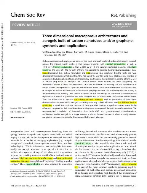
Cite this:Chem.Soc.Rev.,2013,42,794Three dimensional macroporous architectures and aerogels built of carbon nanotubes and/or graphene:synthesis and applicationsStefania Nardecchia,Daniel Carriazo,M.Luisa Ferrer,Marı´a C.Gutie ´rrez and Francisco del Monte*Carbon nanotubes and graphene are some of the most intensively explored carbon allotropes in materials science.This interest mainly resides in their unique properties with electrical conductivities as high as 104S cm À1,thermal conductivities as high as 5000W m À1K and superior mechanical properties with elastic moduli on the order of 1TPa for both of them.The possibility to translate the individual properties of these monodimensional (e.g.carbon nanotubes)and bidimensional (e.g.graphene)building units into two-dimensional free-standing thick and thin films has paved the way for using these allotropes in a number of applications (including photocatalysis,electrochemistry,electronics and optoelectronics,among others)as well as for the preparation of biological and chemical sensors.More recently and while recognizing the tremendous interest of these two-dimensional structures,researchers are noticing that the performance of certain devices can experience a significant enhancement by the use of three-dimensional architectures and/or aerogels because of the increase of active material per projected area.This is obviously the case as long as the nanometre-sized building units remain accessible so that the concept of hierarchical three-dimensional organization is critical to guarantee the mass transport and,as consequence,performance enhancement.Thus,this review aims to describe the different synthetic processes used for preparation of these three-dimensional architectures and/or aerogels containing either any or both allotropes,and the different fields of application in which the particular structure of these materials provided a significant enhancement in theefficacy as compared to their two-dimensional analogues or even opened the path to novel applications.The unprecedented compilation of information from both CNT-and graphene-based three-dimensional architectures and/or aerogels in a single revision is also of interest because it allows a straightforward comparison between the particular features provided by each allotrope.Nanoparticles (NPs)and nanocomposites benefiting from the synergy between inorganic and organic compounds are indeed playing a major role in the development of advanced functional materials for a number of emerging applications (e.g.,catalysis,storage and controlled release systems,smart fillers,and bio-technologies).1Within this context,assembling NPs into struc-turally macroscopic structures is of special relevance for the realistic development of any of the above-cited applications because the resulting materials would offer a desirable combi-nation of high internal reactive surface area and straightforward molecular transport through broad ‘‘highways’’leading to such a surface.2These morphologies are also obtained in monolithsexhibiting hierarchical structures that combine micro-,meso-,and macropores—so that the micro and mesoporosity provide high surface areas while the macroporosity guaranties accessi-bility to this surface.Besides morphology,it is obvious that the chemical nature of the monolith also plays a role and will ultimately determine the particular application of these materi-als.For instance,the use of monolithic aerogels based on silica as columns in high-pressure liquid chromatography (HPLC)is quite extended 3–5whereas the electrically conductive framework of monolithic carbon aerogels has determined their preferred application as electrodes in electrochemical devices (supercapa-citors,fuel cells,batteries,etc.).6–8Interestingly,sol–gel chemis-try is one of the most common synthetic processes used for preparation of both silica and carbon hierarchical monoliths.Thus,Tanaka and coworkers first described the preparation of silica columns for HPLC in 19969using a sol–gel process basedInstituto de Ciencia de Materiales de Madrid (ICMM),Consejo Superior deInvestigaciones Cientı´ficas (CSIC),Cantoblanco 28049,Madrid,Spain.E-mail:delmonte@icmm.csic.es;Fax:+34913720623;Tel:+34913349033Received 24th August 2012DOI:10.1039/c2cs35353a/csrChem Soc RevP u b l i s h e d o n 16 N o v e m b e r 2012. D o w n l o a d e d b y U n i v e r s i t y o f S c i e n c e a n d T e c h n o l o g y o f C h i n a o n 01/10/2013 09:10:35.on the hydrolysis and polycondensation of tetramethoxysilane (TMOS)in the presence of polyethylene oxide (PEO)as a tem-plate.10,11Meanwhile and inspired by the seminal work on silica aerogels by Kistler in 1931,12Pekala et al.13first reported on the use of sol–gel chemistry for the achievement of highly cross-linked organic gels that,after supercritical drying and subsequent thermal treatment in an inert atmosphere,resulted in carbon monoliths.The main features that determined the popularization of the sol–gel process are the capability to produce materials in a variety of forms that includes thin films and three-dimensional (3D)architectures,the textural and chemical characteristics of which can be easily tuned for the achievement of co-continuous structures with well defined hierarchical structures for bare silica-or carbon-based materials as well as hybrids and composites.14–18While recognizing the tremendous relevance of silica,hybrid-silica and carbon mono-liths,the focus of this review will not be on these particular materials because there are already excellent reviews and books that cover most of the recent advances in this area.19–25Less revised has been however the preparation and application of composite-based monolithic aerogels and,in particular,of those containing carbon nanotubes (CNTs)and/or Ts and graphene are both allotropes of Ts exhibit a cylindrical hollow nanostructure with the walls formed by one-atom-thick sheets of carbon that are rolled at specific and discrete angles,which ultimately determine whether the individual nanotube shell is a metal or a Ts are categorized as single-,double-or multi-walled CNTs (SWCNTs,DWCNTs or MWCNTs,respectively)depending on the number of the rolled walls.Mean-while,graphene is a planar monolayer of carbon atoms arranged into a two-dimensional (2D)honeycomb lattice with a C–C bond length of 0.142nm.These two well-known allotropes of carbon have attracted much attention from the scientific community because they exhibit unique properties (electrical conductivities as high as 104S cm À1,thermal conductivities as high as 5000W m À1K and superior mechanical properties with elastic moduli on the order of 1TPa,for both of them)26–31that,eventually,can be translated into any architecture built up with any of them.In this review,we will summarize the use of CNTs and graphene oxide (GO)as,respectively,monodimensional (1D)and 2D building units in the synthesis of 3D macroporous architectures and aerogels.We will also describe the great potential of the resulting hydrogels and aerogels in the field of actuators,supercapacitors and polymer composites.T-based 3D architectures and aerogelsSince their discovery in 1991,32CNTs have been the subject of numerous research works given their unique properties,for example,extremely high electrical conductivities,very high thermal conductiv-ities,and outstanding mechanical properties.However,the proces-sing of CNT-based materials into engineered 3D macroporous structures is still in its infancy and most of the arrays prepared to date with controlled areas and nanotube lengths are 2D-type;e.g.well vertically aligned CNT architectures,33,34self-assembled CNTStefania Nardecchia,Francisco del Monte,M.Luisa Ferrer,Daniel Carriazo and Marı´a C.Gutie ´rrez Stefania Nardecchia graduated in Industrial Chemistry in 2005at the University of Roma ,obtained her PhD from the University of Madrid in 2012.In 2008she joined the Group of Bioinspired Materials at the Institute of Materials Science of Madrid (ICMM-CSIC)where she is currently working.Her research interests focused on materials for drug release and biomaterials for bone and neural tissue regeneration.Daniel Carriazo obtained his PhD from the University of Salamanca in 2008on the synthesis of layered double hydroxides and porous oxides for catalytic applications.In 2009he joined the Group of Bioinspired Materials at the Institute of Materials Science of Madrid (ICMM-CSIC)where he is currently working.During 2011he spent eight monthsworking in the group headed by Prof.Niederberger at the ETH-Zu¨rich on the synthesis of nano-materials by non-aqueous routes.His present scientific interest is focused on the synthesis of carbonaceous materials with hierarchical porosity for energy storage and environmental applications.Marı´a Luisa Ferrer is a tenured scientist at the Instituto de Ciencia de Materiales de Madrid (ICMM-CSIC).After an MSc degree in Polymer Science (1992),she completed her PhD in chemistry at the University Autonoma of Madrid (1995).She was a postdoctoral fellow over the next three years ,first at the University of Patras (Greece)and ,after that ,at UCLA (USA).After that ,she got a teaching appointment at the UMH (Spain).She joined the ICMM-CSIC in 2000to work on the preparation of hierarchical materials with applications in both energy and biomaterials.Marı´a C.Gutie ´rrez obtained her PhD in Organic Chemistry at the University of Granada in 2001.From 2001to 2003,she worked as a postdoctoral fellow with Prof.Furstoss in Biocatalysis and Fine Chemistry at the Universite´de la Me ´diterrane ´e (France),and participated in European projects from IV and V Framework Programmes.In 2004,she joined the Group of Bioinspired Materials at the ICMM-CSIC in Spain and became a tenured scientist in 2009.Her research interest is the development of New Routes for Preparation of Hierarchical and Multifunctional Materials for Applications in Biotechnology and Biomedicine.Francisco del Monte is a Scientist at the Instituto de Ciencia de Materiales de Madrid (ICMM-CSIC)in Spain.He received a BSc degree in organic chemistry in 1991,an MSc degree in polymer science in 1992,and a PhD in chemistry in 1996.He then spent two years as a post-doctoral fellow at the University of Los Angeles ,California.Since 2004,he leads the Group of Bioinspired Materials at the ICMM-CSIC.His current scientific interest is the use of biomimetic chemistry and deep eutectic solvents for the preparation of hierarchically organized materials.Review ArticleChem Soc RevP u b l i s h e d o n 16 N o v e m b e r 2012. D o w n l o a d e d b y U n i v e r s i t y o f S c i e n c e a n d T e c h n o l o g y o f C h i n a o n 01/10/2013 09:10:35.sheets 35or textiles containing nanotube-fiber capacitors woven in orthogonal directions,36among others.37Eventually,3D sieve architectures have also been constructed,38although the length of the third dimension of the regular patterned cavities is typically limited to that of some few CNTs,39,40except for those composites where the CNT fraction is minor.41The valuable contribution of these works to different applications has been highlighted in recent reviews 42–48and,for this reason,will not be the subject of this review either.Chemical vapor deposition (CVD)techniques have been recently used to prepare 3D structures composed of freestanding films of vertically aligned carbon nanotubes.49Considering the valuable contribution of these 3D structures to different applications,50it is our belief that ‘‘true’’3D architectures—in which the third dimen-sion is within the range of the other two—produced by chemical routes could exhibit interesting properties (e.g.in terms of both electrical conductivity and mechanical properties)for industrial applications.This belief is actually corroborated by the increased number of works dealing with CNT-based 3D architectures pub-lished within the last two years;i.e.ca.65%of the works revised herein correspond to the 2011–2012period.The main reason behind this tremendous activity is that,as a general trend for any catalytic application,the performance of any device based on CNTs can experience a significant enhancement by the use of 3D architectures rather than 2D ones because of the obvious increase of active material in the former case.Hydrogels,organogels,and aerogels based on silica or carbon and consisting of micro-,meso-and even macroporous networks forming a hierarchical structure that guaranties molecular transport throughout the entire 3D architecture to gain access to the internal reactive surface are illustrative examples of 3D macroscopic assemblies corroborating this issue.19–25Thus,the aim of this review with regard to CNTs will be to summarize those self-assembling processes described to date that have been capable of building ‘‘true’’3D hierarchical macro-structures and have explored those applications where silica and carbon monoliths have already proved efficient (e.g.membranes and columns for water treatment and chromatographic separa-tions,electrodes for supercapacitors,fuel cells and batteries,and catalytic substrates,among others).1.1Organogels and aerogels from CNT suspensionsThe organic functionalization of either SWCNTs or MWCNTs with an organogelator can result in the formation of freestanding CNT organogels.For instance,SWCNTs functionalized by ferrocene-grafted poly(p -phenyleneethynylene)can gelate common organic solvents such as chloroform to form robust 3D nanotube networks that cannot be re-dispersed in any organic solvent.51Thermally annealed CNT aerogels were mechanically stable and stiff(Fig.1),highly porous (99%),and exhibited excellent electrical conductivity (ca.1–2S cm À1)and large specific surface area (590–680m 2g À1).52Moreover,Fmoc-protected-amino-acid-based (Fmoc-Phe-OH,where Fmoc stands for N -fluorenyl-9-methoxycarbonyl and Phe for Phenyl-alanine)hydrogels have also been used to incorporate and disperse SWCNT within the gel phase at physiological pH and temperature.53The resulting hydrogels exhibited an intriguing 1D alignment of SWCNTs on the surface of the gel nanofibers that enhanced theelastic properties as well as the thermal stability,and provided a notorious electrical conductivity of 3.1S cm À1to the resulting hydrogels.Meanwhile,the presence of functional groups on MWCNTs that remained available after gelation allowed the conjugation of the properties of gels and nanostructured car-bon materials.54The benefits of using organogelators were therefore multiple considering that,besides inducing gelation and conferring additional properties to the resulting gels,functionalization helps for CNT dispersion at the solution stage and hence,to the achievement of a homogeneous distribution of CNT throughout the resulting gel.Within the context of monomers and polymers,Zhang et al.demonstrated that embedding either MWCNTs or acid-treated MWCNTs into a poly(3,4-ethylenedioxythiophene)–poly(styrene-sulfonate)(PEDOT–PSS)aerogel matrix can significantly enhance the specific surface areas (280–400m 2g À1)of the resulting compo-site aerogels while maintaining good thermal stability and electrical conductivities (1.2–6.9Â10À2S cm À1).55Poly (3-(trimethoxysilyl)propylmethacrylate)(PTMSPMA)can also be used to disperse and functionalize MWCNTs.In this case,strong and permanent chemical bonding between percolated MWCNTs in the resulting free-standing monolithic aerogel was obtained upon the hydrolysis and condensation of PTMSPMA.The entangled MWCNTs generated mesoporous structures on the honeycomb walls,creating aerogels with a surface area of 580m 2g À1(nearly 2-fold the surface area of pristine MWCNTs),remarkable elastic properties and good electrical conductivity (e.g.up to 0.67S cm À1).All these features determined the exceptional pressure and chemical vapor sensing capabilities of these aerogels.56Surfactants have also been used for dispersion of CNT and subsequent formation of aerogels.For instance,Ostojic solubilized SWCNTs in 1%w/v sodium dodecyl sulphate (SDS)aqueous solution.Streptavidin phosphate and DNA complexes were there-after used for SDS replacement and so induce SWCNT gelation.Ethanol and ethanol–water solvent exchange and subsequent critical-point-drying resulted in the formation of SWCNT aerogels exhibiting a previously unobserved peak at 1.3eV in the photo-luminescence spectrum that corresponds to a phonon-assisted recombination of photoexcited charges.57In another interesting example,Yodh and coworkers suspended different concentrations of as-received CNTs (e.g.weight fractions ranging from 5to 13mg mL À1)in water with sodium dodecylbenzene sulfonate.58The suspensions were left overnight to set into elastic gels thatwereFig.1Picture of SWCNT aerogels weighing 17.4mg (density:9.8mg mL À1)before (a),during (b)and after (c)application of a 20g weight.Monoliths were obtained from SWCNTs functionalized with ferrocene-graftedpoly(p -phenyleneethynylene).(Reproduced with permission from ref.52.Copyright (2011)Elsevier Publishing Group).Chem Soc RevReview ArticleP u b l i s h e d o n 16 N o v e m b e r 2012. D o w n l o a d e d b y U n i v e r s i t y o f S c i e n c e a n d T e c h n o l o g y o f C h i n a o n 01/10/2013 09:10:35.subsequently soaked at 901C in aqueous solutions of polyvinyl alcohol (PVA)for structural reinforcement.Reinforced and non-reinforced gels were thereafter submitted to either freeze-or critical-point-drying processes for the achievement of the aero-gel structure.PVA-reinforced aerogels exhibited outstanding mechanical properties (for instance,they were able to hold 8000times their weight,Fig.2)whereas much better conductiv-ities were found for non-reinforced ones (e.g.0.6S cm À1for non-reinforced versus ca.10À5S cm À1for reinforced ones).More recently,Islam and coworkers,using a similar approach in which they substituted PVA by polydimethylsiloxane (PDMS),produced transparent (ca.93%of transmittance for a 3m m-thick aerogel)and stretchable conductors,the electrical conductivity of which (ranging 0.7–1.1S cm À1)remained basically the same under high bending strain.59Transparent SWCNT aerogels can also be obtained using silica as binder (Fig.3a).In this case,SWCNTs were dispersed in water using SDS or sodium deoxy-cholate and then reacted with a silica precursor like TMOS either by a chemical vapor-into-liquid sol–gel process—in which the low boiling point of TMOS allows vapours diffusion through the SWCNT aqueous suspension—or by a regular liquid-phase sol–gel process—in which small aliquots of TMOS are added into the SWCNT aqueous suspension.60After CO 2supercritical drying,the resulting solution-free and surfactant-free SWCNT-silica aerogels provided access to new photophysical properties of SWCNT and hence,converted this solid-state nanomaterial into not only an ideal system for making fundamental optical measurements,but also a novel and suitable platform for the development of applications in sensing,photonics,and opto-electronics in the near future (Fig.3b–d).Within the context of dispersing CNTs in aqueous solutions that also contain a certain molecular precursor in charge of building up the 3D architecture where the CNT will be finally immobilized,the sol–gel polymerization of resorcinol andformaldehyde offers interesting perspectives.For instance,Baumann and coworkers have recently performed a quite extensive and stimulating work on SWCNTs and DWCNTs 3D architectures synthesized by resorcinol–formaldehyde polycondensation.By intro-ducing low concentrations of the sol–gel precursors to a suspension of highly purified SWCNTs,the polymerization was primarily induced on the walls of the CNT bundles and,more importantly,at the junctions between adjacent bundles to form an organic binder.The resulting assembly was dried and subsequently pyrolyzed to convert the organic binder into carbon.61TheaerogelsFig.2(a)Picture of SWCNT aerogels (density:7.5mg mL À1)non-reinforced (left,black coloured)and reinforced (right,gray coloured)with 1wt%PVA.(b)Three PVA-reinforced aerogel monoliths (total mass =13.0mg)supporting 100g (ca.8000times their weight).(c)SEM micrograph revealing themacroporus architecture of PVA-reinforced aerogel (0.5wt%PVA,10mg mL À1CNT content).(d)TEM micrograph of non-reinforced CNT aerogel.(Reproduced with permission from ref.58.Copyright (2007)Wiley-VCH).Fig.3(a)Picture of aerogels without (blank)and with SWCNTs.(b)PL spectrum of aerogels exposed to CO 2,THF,and ether vapors.The PL spectrum of non-exposed (e.g.in vacuum)is also included for comparison.(c)Shift in PL emission wavelength relative to the signal collected under vacuum as a function of SWCNT diameter after exposure of SWNT-aerogels to air (green square),CO 2(red dots),THF (blue triangle),and ether (yellow star).(d)Emission wavelength shifts for SWCNTs with different diameter after alternating exposure to ether and vacuum:(9,5)light blue squares;(7,6)red dots;(7,5)green triangle;and (8,3)blue triangle.(Adapted with permission from ref.60.Copyright (2011)American Chemical Society).Review Article Chem Soc RevP u b l i s h e d o n 16 N o v e m b e r 2012. D o w n l o a d e d b y U n i v e r s i t y o f S c i e n c e a n d T e c h n o l o g y o f C h i n a o n 01/10/2013 09:10:35.could be also prepared with varying SWCNT loading (0–55wt%).62At nanotube loadings of 55wt%,shrinkage of the aerogel monoliths during carbonization and drying was almost completely eliminated and the electrical conductivities improved by an order of magnitude as compared to those of foams without SWCNTs.Particularly interesting in terms of conductivity (up to 8S cm À1)and surface area (above 500m 2g À1)were those composites based on DWCNTs.63Interestingly,the porous network of these architectures can be surface decorated with oxide coatings (Fig.4).64In this case,sol–gel deposition of SiO 2,SnO 2or TiO 2produced a conformal overlayer on the primary ligament structure of the SWCNT-based support,thus preserving open porosity within the monolithic part.The result-ing aerogels (SWCNT-CA)exhibited good electrical conductivity (up to 1S cm À1)and an enhancement in the mechanical properties relative to the uncoated SWCNT-CA support that should prove advantageous for a number of applications,such as battery electrodes,sensing devices,and catalysts.Morerecently,Gutie´rrez et al.have studied the polycondensation of not only resorcinol and formaldehyde 65but also furfuryl alco-hol 66in deep eutectic solvents (DES)because of their capability to homogeneously disperse high amounts of CNTs.In the furfuryl alcohol case,the presence of DES induced the formation of monolithic carbons with a bimodal porosity that comprises from micro-up to macropores.The morphology of the resulting carbons (C FA ,without CNTs)consisted of a bicontinuous porous network built of highly cross-linked clusters that aggregated and assembled into a stiff,interconnected structure (Fig.5).This sortof morphology is typical of carbons obtained via spinodal decomposition processes where the formation of a rich-polymer phase by polycondensation is accompanied by the segregation of the non-condensed matter (creating first a poor-polymer phase that,ultimately,becomes a depleted-polymer phase),the elimina-tion of which (either before carbonization by washing or during carbonization by thermal decomposition)results in the formation of the above-mentioned bicontinuous porous structure.67In this particular case,furfuryl alcohol condensated on the walls of the MWCNTs so that the resulting bicontinuous porous network resembled a skeleton network composed of interconnected MWCNTs ‘‘glued’’by the carbon resulting from the furfuryl alcohol condensation and pyrolysis (C FACNT ).The presence of a carbon shell that coated every MWCNT and formed strong junctions between them was reflected in both the electrical conductivity (up to 4.8S cm À1,as measured by the four-probe method)and the elastic character (Young’s modulus,11MPa)of the monoliths having the largest MWCNT content.The combi-nation of high electrical conductivity,hierarchical structure and pseudo elastic properties contributed to retain 75%of theinitialFig.4SEM images of (a and b)as-synthesized and (c and d)annealed at 3201C TiO 2/SWCNT-CA composites at low and high magnifications.TEM images of annealed (e and f)TiO 2–SWCNT-CA composites at low and high magnifications.Inset in (f)is the electron diffraction pattern of the annealed TiO 2/SWCNT-CA.(Reproduced with permission from ref.64.Copyright (2011)American ChemicalSociety).Fig.5SEM micrographs of C FA (a,b and c),C FACNT1(d)and C FACNT5(f,h and i).TEM micrographs of colloidal carbon corresponding to C FA and C FACNT1(c),and fibrillar carbon corresponding to C FACNT1and C FACNT5(e and g).(Reproduced with permission from ref.66.Copyright (2011)Wiley-VCH).Chem Soc Rev Review ArticleP u b l i s h e d o n 16 N o v e m b e r 2012. D o w n l o a d e d b y U n i v e r s i t y o f S c i e n c e a n d T e c h n o l o g y o f C h i n a o n 01/10/2013 09:10:35.capacitance at current densities of up to 765mA cm À2(29A g À1)when two of these monoliths (each monolith was 1.2cm in diameter and 1.1mm in height,and weighed 17mg)were assembled into a supercapacitor cell.It is also worth noting those works using polymers that can play an ‘‘all-in-one’’role as both dispersing agents helping to the achievement of homogeneous aqueous suspensions of CNT and structural binders holding the 3D architecture formed after any sort of processing (e.g.freeze-drying,electrospun,etc.).For instance,Tasis and coworkers used PVA as a dispersing-aid agent of KMnO 4-treated MWCNTs in water.The application of flash freezing to the MWCNT/PVA aqueous suspension (e.g.in liquid nitrogen)and subsequent freeze-drying resulted in MWCNT aerogels that exhibited interesting thermal and cata-lytic properties as well as absorption capacity of polynuclear aromatic substances.68This ‘‘all-in-one’’approach can be further extended upon the use of different polymers.For instance,del Monte and coworkers used chitosan for disper-sing HNO 3-treated MWCNTs (up to 8wt%)in water.69MWCNT aerogels were obtained upon the application of the ISISA (ice segregation induced self-assembly)process that basically con-sists of a unidirectional freezing of the sample (e.g.by dipping it into a nitrogen liquid bath at a constant rate)followed by freeze-drying.70In this case,unidirectional freezing allowed the achievement of macroporous structures with well-aligned micro-channels in the freezing direction and a well-patterned morphol-ogy between channels (mellar and microhoneycomb,respectively)(Fig.6).These ultralightweight aerogels (specific gravity ranging from 4.9Â10À2to 9.4Â10À2along with the MWCNT content)exhibited remarkable electrical conductivities of up to 2.5S cm À1for those aerogels composed of 89wt%MWCNTs and 11wt%CHI.Interestingly,the aerogel structure could be reinforced upon exposure to glutaraldehyde vapors without detri-mental effects on either the morphology or the electrical con-ductivity.71These features allowed the use of these aerogels as high-perfomance 3D electrodes in both direct methanol and microbial fuel cells (DMFCs and MFCs,respectively).69,72Particularly interesting was the microchanneled structure in this latter case,allowing the possibility to work in the ‘‘flow-through’’mode so that bacteria could colonize the entire internal structure of cylindrical aerogels of ca.4mm in diameter and 12mm in height (Fig.7)that,otherwise (e.g.in static conditions),was not possible.73The validity of these aerogels to work as high-perfo-mance 3D electrodes under ‘‘flow-through’’conditions was not only demonstrated in MFCs,but also for electrodeposition of a layer of calcium–phosphate salts homogenously distributed throughout the entire internal surface of the aerogels.Interest-ingly,the crystal habit of the deposited mineral was easily controlled by the electrodeposition conditions (Fig.8).74It is worth noting that,as in the previous case,homogeneous coatings were not attained upon chemical mineralization carried out under non-flow conditions.71More recently,the same group has explored the capability of different polysaccharides (e.g.chondroi-tin sulphate)and protein-like polymers (e.g.gelatin)for the preparation of analogue MWCNT aerogels.75The authors have also explored the potential application of these MWCNT aerogels as scaffolds for tissue engineering purposes.71,74–761.2.CNT-surface modified aerogelsCNT functionalization of the internal surface of preformed aerogels has recently gained increased interest because it offers a tremendous versatility considering the existing palette of 3D architectures that may be suitable for this purpose.For instance,Petrov and coworkers reported on the ice-mediated deposition of individual CNTs onto the inner surface of a pre-formed macroporous polymer cryogel.77Fig.6SEM micrographs of MWCNT scaffolds:(a)cross-section view,(b)longitudinal view according to plane 1and (c)longitudinal view according to plane 2.Bars are 200m m in every case.(Reproduced with permission from ref.74.Copyright (2012)Wiley-VCH).Fig.7SEM images (a–c)of biofilm at different magnifications taken from the inner part of the 3D scaffold.(Adapted with permission from ref.72.Copyright (2011)Royal Society of Chemistry).Review ArticleChem Soc RevP u b l i s h e d o n 16 N o v e m b e r 2012. D o w n l o a d e d b y U n i v e r s i t y o f S c i e n c e a n d T e c h n o l o g y o f C h i n a o n 01/10/2013 09:10:35.。
chemical physics letters分区-回复以下是一份针对"chemical physics letters分区"主题的1500-2000字文章。
文章将为读者提供关于该主题的详细解释和分步回答。
Title: Understanding Chemical Physics Letters Journal and Its CategorizationIntroduction:In the realm of scientific research, academic journals play a pivotal role in disseminating knowledge and driving progress in various disciplines. Researchers and scholars often strive to publish their work in reputable journals, respected within their respective fields. Chemical Physics Letters is a prominent journal catering to the interdisciplinary niche of chemical physics. This article aims to provide a comprehensive explanation of Chemical Physics Letters, its significance, and its categorization within the scientific community.1. Chemical Physics Letters: An OverviewChemical Physics Letters (CPL) is an esteemed scientific journal that publishes groundbreaking research in the field of chemical physics. Founded in 1970, CPL has been instrumental in promotinginterdisciplinary research encompassing both chemistry and physics. It serves as a platform for scientists to share their discoveries, theories, and experimental data, facilitating collaboration and advancement in the field.2. Scope and Content:CPL focuses on a wide range of topics, including molecular dynamics, spectroscopy, quantum chemistry, computational chemistry, chemical kinetics, and surface science. The journal welcomes contributions that highlight the interface between chemistry and physics, encouraging scientists to explore novel approaches towards understanding chemical phenomena using physical principles.3. Editorial Process and Peer Review:Chemical Physics Letters adopts a rigorous peer-review process to ensure that publications meet high scientific standards. After submission, manuscripts undergo a thorough evaluation by subject matter experts, who scrutinize the quality, significance, and originality of the research. This critical appraisal helps maintain the journal's credibility by identifying flaws, suggesting revisions, and selecting the most cutting-edge research for publication.4. Impact Factor and Reputation:The impact factor (IF) is a widely used metric to assess the influence and relevance of academic journals. It quantifies the average number of citations received by articles published in a particular journal over a specific period. Chemical Physics Letters consistently achieves an excellent impact factor, implying that the research published within its pages garners substantial attention from the scientific community. A high IF reflects the journal's reputation and the significance of the research it showcases.5. Categorization and Ranking:To facilitate better navigation for researchers, academic journals are categorized, often referred to as journal indexing. Chemical Physics Letters falls into the Chemical Physics category, marking its specialization as a journal bridging the gap between chemistry and physics. Within this category, CPL has established itself as one of the leading publications, displaying a consistently impressive impact factor and attracting high-quality research submissions.6. Practical Implications:The categorization and reputation of Chemical Physics Letters holdpractical implications for researchers in the field of chemical physics. By submitting their research to CPL, scientists have the opportunity to gain exposure, reach a wide audience, and receive constructive feedback from experts in the field. Additionally, publications within Chemical Physics Letters can enhance researchers' academic credentials, contributing to career development and the potential for future collaborations.Conclusion:Chemical Physics Letters' consistent publication of cutting-edge research, interdisciplinary focus, and high impact factor make it a sought-after platform for researchers in the field of chemical physics. By bridging the gap between chemistry and physics, CPL facilitates the advancement of knowledge and fosters collaboration. Its categorization within the Chemical Physics index confirms its prominence and relevance within the scientific community. As research continues to push boundaries, Chemical Physics Letters is likely to maintain its pivotal role as a platform for groundbreaking discoveries and innovative ideas in the field.。
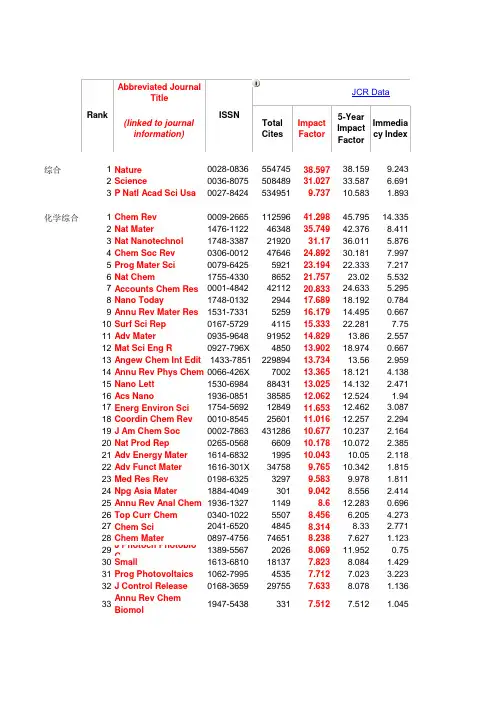
Abbreviated JournalTitle(linked to journal information)Total CitesImpact Factor5-YearImpactFactor Immediacy Index综合1Nature 0028-0836********.59738.1599.2432Science0036-807550848931.02733.587 6.6913P Natl Acad Sci Usa 0027-84245349519.73710.583 1.893化学综合1Chem Rev 0009-266511259641.29845.79514.3352Nat Mater 1476-11224634835.74942.3768.4113Nat Nanotechnol 1748-33872192031.1736.011 5.8764Chem Soc Rev 0306-00124764624.89230.1817.9975Prog Mater Sci 0079-6425592123.19422.3337.2176Nat Chem 1755-4330865221.75723.02 5.5327Accounts Chem Res 0001-48424211220.83324.633 5.2958Nano Today 1748-0132294417.68918.1920.7849Annu Rev Mater Res 1531-7331525916.17914.4950.66710Surf Sci Rep 0167-5729411515.33322.2817.7511Adv Mater 0935-96489195214.82913.86 2.55712Mat Sci Eng R 0927-796X 485013.90218.9740.66713Angew Chem Int Edit 1433-785122989413.73413.56 2.95914Annu Rev Phys Chem 0066-426X 700213.36518.121 4.13815Nano Lett 1530-69848843113.02514.132 2.47116Acs Nano 1936-0851*******.06212.524 1.9417Energ Environ Sci 1754-56921284911.65312.462 3.08718Coordin Chem Rev 0010-85452560111.01612.257 2.29419J Am Chem Soc 0002-786343128610.67710.237 2.16420Nat Prod Rep 0265-0568660910.17810.072 2.38521Adv Energy Mater 1614-6832199510.04310.05 2.11822Adv Funct Mater 1616-301X 347589.76510.342 1.81523Med Res Rev 0198-632532979.5839.978 1.81124Npg Asia Mater 1884-40493019.0428.556 2.41425Annu Rev Anal Chem 1936-132711498.612.2830.69626Top Curr Chem 0340-102255078.456 6.205 4.27327Chem Sci 2041-652048458.3148.33 2.77128Chem Mater 0897-4756746518.2387.627 1.12329J Photoch Photobio C 1389-556720268.06911.9520.7530Small 1613-6810181377.8238.084 1.42931Prog Photovoltaics 1062-799545357.7127.023 3.22332J Control Release 0168-3659297557.6338.078 1.13633Annu Rev Chem Biomol 1947-54383317.5127.512 1.04534Int Mater Rev 0950-660822557.487.1491.188RankISSNJCR Data35Chemsuschem1864-563150567.4757.951 1.189 36Prog Solid State Ch0079-678614747.429 3.3380 37Nano Res1998-012430317.3927.8010.979 38Prog Surf Sci0079-681619047.1369.140.273 39Adv Carbohyd Chem Bi0065-23188337.133 5.8460.75 40Green Chem1463-926215554 6.828 6.992 1.269 41Adv Organomet Chem0065-3055841 6.758.9410 42Curr Opin Colloid In1359-02944670 6.6297.0360.884 43J Phys Chem Lett1948-71858575 6.585 6.651 1.301 44Top Organometal Chem1436-60021152 6.384 1.762 45Chem Commun1359-7345122728 6.378 6.226 1.53 46Catal Rev0161-49402529 6.37510.1750.889 47Trac-Trend Anal Chem0165-99367327 6.351 6.7610.92 48Nanoscale2040-33647835 6.233 6.262 1.167 49Adv Colloid Interfac0001-86867115 6.1698.01 1.32 50Org Lett1523-706073440 6.142 5.563 1.572 51Mater Today1369-70213769 6.0718.677 1.977 52Prog Nucl Mag Res Sp0079-65651993 6.022 6.065 1.389 53Crit Rev Solid State1040-8436744 5.9477.3681 54Carbon0008-622332742 5.868 6.35 1.197 55Chem-Eur J0947-653960788 5.831 5.623 1.241 56Appl Catal B-Environ0926-337323011 5.825 6.0310.965 57J Catal0021-951734516 5.787 6.249 1.025 58Wires Comput Mol Sci1759-0876570 5.738 5.738 3.518 59Lab Chip1473-019716485 5.697 6.136 1.256 60Anal Chem0003-270096794 5.695 5.7690.948 61J Med Chem0022-262359227 5.614 5.383 1.225 62Adv Synth Catal1615-415015502 5.535 5.323 1.109 63Curr Opin Solid St M1359-02862508 5.4387.3290.913 64Biosens Bioelectron0956-566322068 5.437 5.389 1.105 65J Chem Theory Comput1549-961811067 5.389 5.936 1.067 66Biomacromolecules1525-779724209 5.371 5.750.721 67Acs Catal2155-54351461 5.265 5.265 1.222 68Adv Catal0360-05641399 5.25 5.2860 69Chemcatchem1867-38802718 5.181 5.3070.941 70Mrs Bull0883-******** 5.024 5.590.569 71Acs Appl Mater Inter1944-82448635 5.008 5.040.683 72Electroanal Chem0070-977837757.50.25 73J Comb Chem1520-47662925 4.933 3.10274Int Rev Phys Chem0144-235X1524 4.92 5.595 2.231 75J Phys Chem C1932-744778595 4.814 5.1520.738 76Pharm Res-Dordr0724-874119035 4.742 5.0460.735 77Cryst Growth Des1528-748322310 4.689 4.8730.869 78Sol Energ Mat Sol C0927-024818447 4.63 5.205 1.215 79J Chromatogr A0021-967363419 4.612 4.5820.71480Inorg Chem0020-166985446 4.593 4.5510.956 81Bioconjugate Chem1043-180213900 4.58 4.7960.768 82Chem-Asian J1861-47286084 4.572 4.488 1.04683J Org Chem0022-326396723 4.564 4.135 1.101 84Anal Chim Acta0003-267039448 4.387 4.3440.684 85Chem Rec1527-89991375 4.377 4.814 1.533 86Int J Plasticity0749-64195276 4.356 4.70.862 87J Chem Inf Model1549-959611250 4.304 4.0670.795 88Langmuir0743-7463106920 4.187 4.4160.793 89Organometallics0276-733339735 4.145 3.653 1.004 90Ultraschall Med0172-46141247 4.116 2.723 1.286 91J Flow Chem2062-249X61 4.091 4.091 1.143 92Curr Med Chem0929-867312773 4.07 4.4710.627 93Struct Bond0081-59931899 4.068 4.24894Mar Drugs1660-33971871 3.978 3.9110.428 95Analyst0003-265416152 3.969 3.9040.785 96Acta Mater1359-645434860 3.941 4.3950.781 97Soft Matter1744-683X15943 3.909 4.35 1.013 98Crystengcomm1466-803312988 3.879 4.0690.863 99Acs Chem Neurosci1948-7193634 3.871 3.9570.729 100Nanotechnology0957-448434133 3.842 3.8380.697 101Org Electron1566-11995856 3.836 4.0210.63 102J Comput Chem0192-865124682 3.835 4.4010.847 103Phys Chem Chem Phys1463-907640969 3.829 3.976 1.052 104Faraday Discuss1359-66405758 3.821 4.148 2.369 105Dalton T1477-922638660 3.806 3.8890.947 106Catal Sci Technol2044-47531079 3.753 3.753 1.024 107Sci Technol Adv Mat1468-69962352 3.752 3.6440.235 108Chembiochem1439-42279616 3.74 3.670.78 109Curr Top Med Chem1568-02664850 3.702 3.8850.655 110Chem Res Toxicol0893-228X10785 3.667 4.0130.807 111Anal Bioanal Chem1618-264221971 3.659 3.7560.727 112Acs Comb Sci2156-8952379 3.636 3.6360.596 113Corros Sci0010-938X18210 3.615 4.0160.757 114J Phys Chem B1520-6106119722 3.607 3.7020.66 115J Am Soc Mass Spectr1044-03058760 3.592 3.5030.925 116J Cheminformatics1758-2946315 3.59 3.6710.314 117Org Biomol Chem1477-052018355 3.568 3.490.952 118Ultrasound Obst Gyn0960-76928490 3.557 3.7080.756 119Colloid Surface B0927-776510312 3.554 3.4170.707 120Int J Hydrogen Energ0360-319933119 3.548 4.0860.584 121Sensor Actuat B-Chem0925-400529909 3.535 3.6680.527 122Dyes Pigments0143-72087664 3.532 3.4330.897 123Expert Opin Ther Pat1354-37761742 3.525 2.5230.6 124Ultrason Sonochem1350-41775008 3.516 3.708 1.234125J Phys Chem Ref Data0047-26894996 3.5 3.7790.391 126Eur J Med Chem0223-523414818 3.499 3.8490.541 127Talanta0039-914026966 3.498 3.7330.531 128Food Hydrocolloid0268-005X6307 3.494 3.5250.953 129Drug Des Dev Ther1177-8881377 3.4860.256 130Carbohyd Polym0144-861718471 3.479 3.9420.665 131Microchim Acta0026-36724743 3.434 2.8830.5 132Appl Catal A-Gen0926-860X27726 3.41 3.910.506 133J Mech Phys Solids0022-509610460 3.406 3.7460.784 134Pure Appl Chem0033-454513333 3.386 3.1150.382 135Micropor Mesopor Mat1387-181115134 3.365 3.4140.869 136J Biol Inorg Chem0949-82574011 3.353 3.3550.713 137Chemphyschem1439-423511279 3.349 3.3880.768 138Eur J Org Chem1434-193X19346 3.344 3.1370.746 139Food Chem0308-814641375 3.334 4.0720.589 140Acs Med Chem Lett1948-58751087 3.311 3.3180.699 141Future Med Chem1756-89191081 3.31 3.2450.933 142J Nat Prod0163-386419898 3.285 3.2670.787 143Electrophoresis0173-083516985 3.261 2.8690.479 144Bioanalysis1757-61801318 3.253 3.0440.723 145J Mass Spectrom1076-51745573 3.214 3.2270.495 146J Inorg Biochem0162-013410014 3.197 3.430.672 147J Mol Catal A-Chem1381-116917999 3.187 3.3190.496 148J Colloid Interf Sci0021-979744929 3.172 3.390.747 149J Anal Atom Spectrom0267-94777362 3.155 2.9530.725 150Sep Purif Rev1542-2119222 3.154 3.5430.3 151J Pharm Sci-Us0022-354917986 3.13 3.3850.6 152Eur J Inorg Chem1434-194816310 3.12 2.9510.728 153Cement Concrete Res0008-884613854 3.112 3.7460.441 154Curr Org Chem1385-27283953 3.039 3.2220.253 155Isr J Chem0021-21481263 3.025 1.9460.478 156Mar Chem0304-420368723 3.3150.466 157Catal Today0920-586123325 2.98 3.4640.515 158Phytomedicine0944-71135244 2.972 3.2580.401 159New J Chem1144-054610014 2.966 2.920.698 160J Pharmaceut Biomed0731-708514648 2.947 2.8530.562 161Photoch Photobio Sci1474-905X4541 2.923 2.810.538 162Catal Commun1566-73679190 2.915 3.3280.535 163Mater Design0261-30699587 2.913 2.8050.703 164J Agr Food Chem0021-856176046 2.906 3.2880.417 165Bioorgan Med Chem0968-089624911 2.903 3.1510.617 166Crit Rev Anal Chem1040-8347979 2.892 3.690.591 167Microchem J0026-265X3428 2.879 2.85 1.048 168Mini-Rev Med Chem1389-55752893 2.865 2.9210.496 169Mol Divers1381-19911289 2.861 3.090.44170Chemmedchem1860-71793723 2.835 3.0750.788 171J Mol Catal B-Enzym1381-11774943 2.823 2.8050.542 172Scripta Mater1359-646219677 2.821 3.1450.534 173Adv Phys Org Chem0065-3160391 2.818 2.609174Electroanal1040-039710646 2.817 2.8620.462 175Fuel Process Technol0378-******** 2.816 3.4930.49 176Tetrahedron0040-402052981 2.803 2.8990.636 177Beilstein J Org Chem1860-53971405 2.801 2.4750.386 178J Phys Chem A1089-563955641 2.771 2.8560.658 179J Ethnopharmacol0378-874121278 2.755 3.3220.519 180Org Process Res Dev1083-61604311 2.739 2.6670.808 181J Supercrit Fluid0896-84466044 2.732 3.1380.472 182Medchemcomm2040-2503690 2.722 2.7220.603 183Adv Inorg Chem0898-******** 2.714 3.3780.25 184J Electroanal Chem1572-665721687 2.672 2.6760.545 185Int J Photoenergy1110-662X945 2.663 2.240.671 186Synlett0936-521417034 2.655 2.4520.604 187Environ Chem1448-25171390 2.652 2.701 1.075 188Opt Mater Express2159-3930593 2.616 2.6220.815 189Anti-Cancer Agent Me1871-52061386 2.610.239 190Top Catal1022-55284896 2.608 2.7080.238 191J Sep Sci1615-93068094 2.591 2.6380.296 192Anal Biochem0003-269739746 2.582 2.9690.558 193Rsc Adv2046-20691816 2.562 2.5670.695 194J Anal Appl Pyrol0165-23705102 2.56 3.0740.447 195Nanoscale Res Lett1931-75733998 2.524 2.7830.2980951-419813285 2.509 2.6110.49 196Rapid Commun Mass Sp196Sci Adv Mater1947-2935553 2.509 2.5610.301 198React Funct Polym1381-51484515 2.505 2.6530.282 199J Chem Technol Biot0268-25756796 2.504 2.4790.573 200Synthesis-Stuttgart0039-788117999 2.5 2.3840.615 201Microsc Microanal1431-92762043 2.495 3.0770.276 202J Chromatogr B1570-023220776 2.487 2.90.319 203Phytochem Analysis0958-03441895 2.48 2.280.292 204Adv Heterocycl Chem0065-2725888 2.478 2.6170.455 205Chem Biol Drug Des1747-02771940 2.469 2.4090.511 206Int J Mol Sci1422-00674706 2.464 2.7320.313 207Ultrasound Med Biol0301-56297839 2.455 2.8440.251 208Gold Bull0017-15571073 2.434 3.1220.04 209Molecules1420-30497552 2.428 2.6790.329 210Plasmonics1557-1955877 2.425 2.9880.525 211J Photoch Photobio A1010-603013061 2.416 2.6910.299 212Tetrahedron Lett0040-403973763 2.397 2.3760.561 213J Alloy Compd0925-838839264 2.39 2.1610.629 214Phys Status Solidi-R1862-62541437 2.388 2.4320.527215Fluid Phase Equilibr0378-******** 2.379 2.3380.544 216Solvent Extr Ion Exc0736-******** 2.375 2.6090.345 217Beilstein J Nanotech2190-4286309 2.374 2.3740.573 218Plant Food Hum Nutr0921-96681569 2.358 2.7620.25 219Acta Pharmacol Sin1671-40835577 2.354 2.5210.596 220Planta Med0032-094311009 2.348 2.4620.304 221Appl Clay Sci0169-13175590 2.342 2.7980.337 222Bioorg Med Chem Lett0960-894X33460 2.338 2.4270.584 222Macromol Mater Eng1438-74922983 2.338 2.3920.509 222Mol Inform1868-1743344 2.338 2.3460.347 225Russ Chem Rev+0036-021X3092 2.299 2.8130.204 226J Chem Thermodyn0021-96145905 2.297 2.2560.735 227Constr Build Mater0950-06187337 2.293 2.8180.391 228Chemometr Intell Lab0169-74394880 2.291 2.4320.253 229Biophys Chem0301-46224822 2.283 2.0940.649 230Arab J Chem1878-5352299 2.2660.343 231J Ginseng Res1226-8453349 2.2590.34 232Materials1996-19441176 2.247 2.3380.222 233Catal Lett1011-372X9373 2.244 2.2610.351 234Theor Chem Acc1432-881X5484 2.233 3.1510.812 235Fitoterapia0367-326X4706 2.231 2.1390.349 236Mater Lett0167-577X23419 2.224 2.3220.489 237Food Addit Contam A1944-00495142 2.22 2.4420.508 238J Biomol Screen1087-05712357 2.207 2.0890.719 239Platin Met Rev0032-1400735 2.194 2.4760.579 240J Nanopart Res1388-07645724 2.175 2.7210.222 241J Mater Sci0022-246131538 2.163 2.10.543 242Adv Quantum Chem0065-3276869 2.161 1.6940.308 242Colloid Polym Sci0303-402X5657 2.161 2.1140.433 244Chem Phys Lett0009-261455163 2.145 2.150.485 244J Ind Eng Chem1226-086X2264 2.145 1.9550.329 246Tetrahedron-Asymmetr0957-416611707 2.115 2.1430.384 247Appl Surf Sci0169-433231193 2.112 2.0990.33 248Synthetic Met0379-677913916 2.109 2.1020.334 249Colloid Surface A0927-775718414 2.108 2.3330.333 249Mat Sci Eng A-Struct0921-509340513 2.108 2.3490.307 251J Anal Toxicol0146-47602660 2.107 1.7580.429 252Solid State Nucl Mag0926-20401202 2.1 2.0570.711 253J Food Compos Anal0889-15753737 2.088 2.7430.19 254J Environ Monitor1464-03254378 2.085 2.1370.322 255Mater Chem Phys0254-058417174 2.072 2.3950.286 256J Pept Sci1075-26171942 2.071 1.8280.434 257Phytother Res0951-418X8059 2.068 2.4380.444 258Nano-Micro Lett2150-5551205 2.057 1.910.35 259Solid State Ionics0167-273820728 2.046 2.5640.26260Carbohyd Res0008-621514176 2.044 2.1780.357 261J Solid State Chem0022-459618166 2.04 2.2950.392 262Curr Org Synth1570-1794673 2.038 2.9140.76 263Ultrasonics0041-624X3651 2.028 2.0540.456 264Smart Mater Struct0964-17267120 2.024 2.3770.289 265Inorg Chem Commun1387-70036416 2.016 1.8810.434 266Appl Organomet Chem0268-26052866 2.011 1.9220.272 267Electrochem Solid St1099-00628883 2.01 2.0260.596 268J Chem Eng Data0021-956815169 2.004 2.1150.295 269Comb Chem High T Scr1386-207314532 1.9750.268 269J Organomet Chem0022-328X217932 1.9920.527 271Thermochim Acta0040-603111408 1.989 2.0460.327 272J Mol Model1610-29403157 1.984 2.3010.378 273J Therm Anal Calorim1388-61509934 1.982 1.7420.243 274Int J Fatigue0142-11235248 1.976 1.9740.352 275J Vib Control1077-54631649 1.966 1.7360.672 276Chem Phys0301-010412935 1.957 2.0590.592 277J Mater Process Tech0924-013618426 1.953 2.1760.332 277Sensors-Basel1424-82207082 1.953 2.3950.321 279Biomed Chromatogr0269-38792861 1.945 1.8150.385 280J Fluorine Chem0022-11394998 1.939 1.9490.465ArticlesCited Half-life Eigenfactor ®Metrics ScoreArticleInfluenc e® Score8699.6 1.5750820.8448329.7 1.3598717.71238018 1.55663 4.8921768.20.2266114.294141 5.20.2278819.481121 3.70.1543615.607390 3.50.178418.8542370.015018.643126 2.40.054018.927207 6.50.108177.90837 3.20.01489 5.62318>10.00.013647.55389.40.008828.821867 5.10.27819 4.24368.40.00872 6.542227 5.50.53637 3.497299.90.01888.1211078 4.40.37491 5.1891191 2.40.20333 4.012473 1.80.05534 3.461368.20.03818 3.07130997.70.83183 2.99465 5.90.01757 3.141169 1.40.00944 3.344569 4.20.12336 3.006377.20.00647 2.73229 1.90.00155 3.27323 3.90.00716 4.441557.70.01045 2.068458 1.40.02121 2.833576 6.70.15215 2.032167.90.00342 3.148457 3.60.07856 2.503112 4.60.01202 1.97501 6.90.05008 1.9062220.00197 2.73916>10.00.003282.792Eigenfactor®Metrics286 2.60.0208 2.0046>10.00.00142 1.13896 2.80.01517 2.301119.20.00397 3.974>10.00.00086 1.894 44940.03848 1.5233>10.00.00076 2.537437.60.01013 2.301 63220.04884 2.393 2150.003483173 4.80.28954 1.5629>10.00.00211 3.009 138 5.80.01695 1.794 1015 1.70.02966 1.597 508.20.01226 2.37 160850.18182 1.40244 5.40.01448 3.213188.30.00431 2.295 107.10.00156 2.34 674 6.40.06437 1.6 1916 4.10.1766 1.469 480 5.40.05059 1.419 284>10.00.04014 1.60356 1.20.00194 1.703 617 3.70.05475 1.603 14797.80.17236 1.533 8907.80.09182 1.35 404 4.40.04405 1.352 239.20.00403 2.705 448 4.10.05929 1.252 507 3.50.04948 1.865 480 5.30.05919 1.416 315 1.30.00585 1.6362>10.00.00057 1.543 255 2.10.01222 1.495 116 6.20.01779 2.376 953 2.30.03563 1.2844>10.00.00016 2.2160 5.10.006940.708137.90.00319 2.303 3283 3.40.34957 1.353 2798.70.02859 1.299 773 3.90.057280.943 493 5.30.04212 1.304 11447.10.090460.92115617.50.124780.98 259 5.70.03346 1.295 372 2.80.02555 1.219 1289>10.00.12482 1.03 7277.10.06585 1.03830 5.80.00343 1.39794 6.80.01439 1.685 303 6.60.019140.892 2119 6.70.21487 1.164 9987.10.059110.76263 3.40.002370.436140.000190.962 475 5.50.03101 1.1898.60.00225 1.225 194 2.50.00680.908 817 6.60.031350.985 68170.09849 1.714 1358 2.50.073 1.334 1194 2.60.032550.749 10720.00309 1.26 1021 4.40.12987 1.194 459 3.20.02416 1.192 2618.90.03446 1.396 1804 3.70.15067 1.296 1418.60.01298 1.609 1709 4.50.08330.842 327 1.30.00320.94181 4.90.00904 1.23 327 4.70.03579 1.258 17750.0131 1.044 2597.10.02119 1.078 877 4.30.068460.99799 1.40.001410.915 449 6.30.028910.786 16157.50.18356 1.081 22860.020170.96535 1.90.00176 1.224 1160 3.80.055440.914 201 6.30.017610.949 426 4.10.025740.772 2120 3.70.074070.708 1016 5.80.054290.757 321 5.50.013530.63690 3.30.006210.726 184 4.80.010070.73123>10.00.00228 1.513 610 3.80.032170.72 842 5.40.057730.829 213 5.40.01270.77439 2.40.001731002 4.80.033670.729 208 4.30.00930.537 5247.60.043570.93 116>10.00.02104 1.812 173>10.00.013330.936 589 5.30.032210.807 108 6.10.009190.931 487 4.70.03951 1.142 76450.047770.779 1666 5.20.091160.854 193 1.80.004620.921 120 2.20.004670.894 3338.70.027140.756 4327.10.027040.625 19520.003610.533 194 6.90.011710.909 2597.30.013360.716 266 6.80.026850.752 87080.070140.869 2187.70.01310.75610 5.60.00062 1.012 4189.20.026590.815 622 5.20.034970.666 1709.90.01712 1.222 178 5.80.009120.836 907.70.00320.65258>10.00.01221 1.371 4877.30.041850.896 187 5.60.009820.662 338 6.50.019280.711 443 6.30.026840.651 20850.01330.806 409 4.50.027060.735 774 3.20.034350.762 15287.90.107180.745 739 5.40.053960.715 227.60.001180.774 105 5.10.007480.647 129 4.90.00780.74475 3.50.002990.639212 3.70.013920.784 201 5.60.009290.599 500 6.30.06138 1.238 >10.00.00042 1.049 290 6.10.019640.625 251 5.60.017330.895 12498.40.075460.68 241 2.20.005560.628 1341 6.70.120620.829 651 6.90.026690.572 224 5.10.010210.672 290 5.30.013220.702 194 1.60.002660.7278>10.00.000620.792 314>10.00.019270.649 32830.001390.381 520 6.30.034550.62153 5.20.004350.904 200 1.30.002460.856 109 3.70.00563143 5.80.013670.825 439 4.20.025470.66 441>10.00.03210.853 17290.80.002020.494 1527.40.009010.741 624 2.40.016810.714 337 6.40.02850.71 173 1.90.002010.614 124 6.30.008010.593 2207.60.010810.602 4708.20.028730.596 221 5.20.00853 1.29 4957.50.036490.714 967.20.003150.52311>10.00.000450.543 184 3.50.006730.588 1064 2.80.017560.666 2437.60.014140.744 257.10.002380.868 105130.022770.574 10130.003550.834 2518.20.017620.63 16669.90.081330.508 1478 4.10.10840.548 14830.008560.8753427.80.015630.587 559.80.002470.6496 1.50.001250.668648.10.002270.561 178 6.20.010850.6 247>10.00.011750.526 202 5.20.013550.701 1484 5.40.069550.546 116 6.40.005740.60572 2.10.00140.58954>10.00.004010.856 351 6.60.011110.57 960 3.90.021660.681 1549.50.006150.597 5790.008180.646 6720.0008353 2.30.00061176 2.60.005320.633 1947.80.016490.569 223 5.60.014960.968 25280.006360.457 1626 5.50.049760.537 1977.10.008730.585 128 5.40.00580.57919>10.00.001080.734 650 3.70.017210.673 9419.10.050830.59113>10.00.00130.598 21090.007690.475 906>10.00.066080.687 350 3.90.005590.396 2247.80.01640.479 1789 5.50.074220.539 419>10.00.014550.491 579 6.80.034280.585 11717.30.084950.73 918.60.003920.471 458.60.00220.655 100 6.20.007370.666 335 5.10.012850.644 964 5.50.038290.59199 5.20.004810.478 302 6.60.012460.48640 2.10.000610.345 392>10.00.021350.719339>10.00.01560.489 5138.90.025150.615 50 4.50.001620.659 1368.50.005580.639 353 5.90.018730.713 495 4.80.011170.321 1147.60.003960.391 156 6.70.022520.706 508 6.50.027410.476 82 5.10.003380.472 410>10.00.020760.421 400>10.00.012770.531 463 4.70.008250.53 728 5.70.012880.253 2367.10.012090.669 180 3.80.004490.45 360>10.00.018270.679 2957.80.035210.653 950 3.40.026580.586 218 5.20.006840.446 2547.50.007820.487。
刊名简称刊名全称ISSN PLOS PATHOG PLoS Pathogens1553-7366 REV MED VIROL REVIEWS IN MEDICAL VIROLOGY1052-9276 ADV VIRUS RES ADVANCES IN VIRUS RESEARCH0065-3527 AIDS AIDS0269-9370 ANTIVIR THER ANTIVIRAL THERAPY1359-6535 J VIROL JOURNAL OF VIROLOGY0022-538X RETROVIROLOGY Retrovirology 1742-4690 ANTIVIR RES ANTIVIRAL RESEARCH0166-3542 INFLUENZA OTHER RESP Influenza and Other Respiratory Viruses1750-2640 INT J MED MICROBIOL INTERNATIONAL JOURNAL OF MEDICAL MICROBIOLOGY1438-4221 J CLIN VIROL JOURNAL OF CLINICAL VIROLOGY1386-6532 J GEN VIROL JOURNAL OF GENERAL VIROLOGY0022-1317 J MED VIROL JOURNAL OF MEDICAL VIROLOGY0146-6615 J VIRAL HEPATITIS JOURNAL OF VIRAL HEPATITIS1352-0504 MICROBES INFECT MICROBES AND INFECTION1286-4579 VIROLOGY VIROLOGY0042-6822 ACTA VIROL ACTA VIROLOGICA0001-723X AIDS RES HUM RETROV AIDS RESEARCH AND HUMAN RETROVIRUSES0889-2229 ARCH VIROL ARCHIVES OF VIROLOGY0304-8608 CURR HIV RES CURRENT HIV RESEARCH1570-162X FOOD ENVIRON VIROL Food and Environmental Virology1867-0334 FUTURE VIROL Future Virology1746-0794 INDIAN J VIROL Indian Journal of Virology 0970-2822 INTERVIROLOGY INTERVIROLOGY0300-5526 J NEUROVIROL JOURNAL OF NEUROVIROLOGY1355-0284 J VIROL METHODS JOURNAL OF VIROLOGICAL METHODS0166-0934 S AFR J HIV MED SOUTHERN AFRICAN JOURNAL OF HIV MEDICINE1608-9693 VIRAL IMMUNOL VIRAL IMMUNOLOGY0882-8245 VIROL J Virology Journal1743-422X VIROLOGIE VIROLOGIE1267-8694 VIRUS GENES VIRUS GENES0920-8569 VIRUS RES VIRUS RESEARCH0168-1702 VIRUSES-BASEL Viruses-Basel1999-4915 ACTA NEUROPATHOL ACTA NEUROPATHOLOGICA0001-6322 AM J PATHOL AMERICAN JOURNAL OF PATHOLOGY0002-9440 ANNU REV PATHOL-MECH Annual Review of Pathology-Mechanisms of Disease1553-4006 J PATHOL JOURNAL OF PATHOLOGY0022-3417 AM J SURG PATHOL AMERICAN JOURNAL OF SURGICAL PATHOLOGY0147-5185 BRAIN PATHOL BRAIN PATHOLOGY1015-6305 DIS MODEL MECH Disease Models & Mechanisms1754-8403 EXPERT REV MOL DIAGN EXPERT REVIEW OF MOLECULAR DIAGNOSTICS1473-7159 HISTOPATHOLOGY HISTOPATHOLOGY0309-0167 J MOL DIAGN JOURNAL OF MOLECULAR DIAGNOSTICS1525-1578 J NEUROPATH EXP NEUR JOURNAL OF NEUROPATHOLOGY AND EXPERIMENTAL NEURO0022-3069 LAB INVEST LABORATORY INVESTIGATION0023-6837 MODERN PATHOL MODERN PATHOLOGY0893-3952 NEUROPATH APPL NEURO NEUROPATHOLOGY AND APPLIED NEUROBIOLOGY0305-1846 SEMIN IMMUNOPATHOL Seminars in Immunopathology1863-2297 ADV ANAT PATHOL ADVANCES IN ANATOMIC PATHOLOGY1072-4109 ALZ DIS ASSOC DIS ALZHEIMER DISEASE & ASSOCIATED DISORDERS0893-0341 AM J CLIN PATHOL AMERICAN JOURNAL OF CLINICAL PATHOLOGY0002-9173ANAL CELL PATHOL Analytical Cellular Pathology-Cellular Oncology2210-7177 ARCH PATHOL LAB MED ARCHIVES OF PATHOLOGY & LABORATORY MEDICINE0003-9985 CANCER CYTOPATHOL CANCER CYTOPATHOLOGY1934-662X CYTOM PART B-CLIN CY CYTOMETRY PART B-CLINICAL CYTOMETRY1552-4949 DIS MARKERS DISEASE MARKERS0278-0240 EXP MOL PATHOL EXPERIMENTAL AND MOLECULAR PATHOLOGY0014-4800 HISTOL HISTOPATHOL HISTOLOGY AND HISTOPATHOLOGY0213-3911 HUM PATHOL HUMAN PATHOLOGY0046-8177 INT J EXP PATHOL INTERNATIONAL JOURNAL OF EXPERIMENTAL PATHOLOGY0959-9673 INT J IMMUNOPATH PH INTERNATIONAL JOURNAL OF IMMUNOPATHOLOGY AND PHA0394-6320 J CLIN PATHOL JOURNAL OF CLINICAL PATHOLOGY0021-9746 PATHOBIOLOGY PATHOBIOLOGY1015-2008 PATHOLOGY PATHOLOGY0031-3025 TISSUE ANTIGENS TISSUE ANTIGENS0001-2815 TOXICOL PATHOL TOXICOLOGIC PATHOLOGY0192-6233 VIRCHOWS ARCH VIRCHOWS ARCHIV-AN INTERNATIONAL JOURNAL OF PATH0945-6317 ACTA CYTOL ACTA CYTOLOGICA0001-5547 AM J FOREN MED PATH AMERICAN JOURNAL OF FORENSIC MEDICINE AND PATHOL0195-7910 ANN DIAGN PATHOL Annals of Diagnostic Pathology 1092-9134 ANN PATHOL ANNALES DE PATHOLOGIE0242-6498 APMIS APMIS0903-4641 APPL IMMUNOHISTO M M APPLIED IMMUNOHISTOCHEMISTRY & MOLECULAR MORPHOL1062-3345 BRAIN TUMOR PATHOL Brain Tumor Pathology1433-7398 CARDIOVASC PATHOL CARDIOVASCULAR PATHOLOGY1054-8807 CLIN NEUROPATHOL CLINICAL NEUROPATHOLOGY0722-5091 CYTOPATHOLOGY CYTOPATHOLOGY0956-5507 DIAGN CYTOPATHOL DIAGNOSTIC CYTOPATHOLOGY8755-1039 DIAGN MOL PATHOL DIAGNOSTIC MOLECULAR PATHOLOGY1052-9551 DIAGN PATHOL Diagnostic Pathology1746-1596 ENDOCR PATHOL ENDOCRINE PATHOLOGY1046-3976 EXP TOXICOL PATHOL EXPERIMENTAL AND TOXICOLOGIC PATHOLOGY0940-2993 FETAL PEDIATR PATHOL Fetal and Pediatric Pathology1551-3815 FOLIA NEUROPATHOL FOLIA NEUROPATHOLOGICA1641-4640 FORENSIC SCI MED PAT Forensic Science Medicine and Pathology1547-769X INDIAN J PATHOL MICR Indian Journal of Pathology and Microbiology0377-4929 INT J GYNECOL PATHOL INTERNATIONAL JOURNAL OF GYNECOLOGICAL PATHOLOGY0277-1691 INT J SURG PATHOL INTERNATIONAL JOURNAL OF SURGICAL PATHOLOGY1066-8969 J COMP PATHOL JOURNAL OF COMPARATIVE PATHOLOGY0021-9975 J CUTAN PATHOL JOURNAL OF CUTANEOUS PATHOLOGY0303-6987 J ORAL PATHOL MED JOURNAL OF ORAL PATHOLOGY & MEDICINE0904-2512 J TOXICOL PATHOL Journal of Toxicologic Pathology0914-9198 KOREAN J PATHOL Korean Journal of Pathology1738-1843 LEPROSY REV LEPROSY REVIEW0305-7518 MED MOL MORPHOL Medical Molecular Morphology1860-1480 MED NUCL Medecine Nucleaire-Imagerie Fonctionnelle et Met0928-1258 NEUROPATHOLOGY NEUROPATHOLOGY0919-6544 PATHOL BIOL PATHOLOGIE BIOLOGIE0369-8114 PATHOL INT PATHOLOGY INTERNATIONAL1320-5463 PATHOL ONCOL RES PATHOLOGY & ONCOLOGY RESEARCH1219-4956 PATHOL RES PRACT PATHOLOGY RESEARCH AND PRACTICE0344-0338 PATHOLOGE PATHOLOGE0172-8113 PEDIATR DEVEL PATHOL PEDIATRIC AND DEVELOPMENTAL PATHOLOGY1093-5266POL J PATHOL POLISH JOURNAL OF PATHOLOGY1233-9687 SCI JUSTICE SCIENCE & JUSTICE1355-0306 SEMIN DIAGN PATHOL SEMINARS IN DIAGNOSTIC PATHOLOGY0740-2570 ULTRASTRUCT PATHOL ULTRASTRUCTURAL PATHOLOGY0191-3123 VET PATHOL VETERINARY PATHOLOGY0300-9858 POLYM TEST POLYMER TESTING0142-9418 PROG CRYST GROWTH CH PROGRESS IN CRYSTAL GROWTH AND CHARACTERIZATION 0960-8974 EXP MECH EXPERIMENTAL MECHANICS0014-4851 MATER CHARACT MATERIALS CHARACTERIZATION1044-5803 NANOSC MICROSC THERM Nanoscale and Microscale Thermophysical Engineer1556-7265 NDT&E INT NDT & E INTERNATIONAL0963-8695 ENG FAIL ANAL ENGINEERING FAILURE ANALYSIS1350-6307 J NONDESTRUCT EVAL JOURNAL OF NONDESTRUCTIVE EVALUATION0195-9298 J SANDW STRUCT MATER JOURNAL OF SANDWICH STRUCTURES & MATERIALS1099-6362 J STRAIN ANAL ENG JOURNAL OF STRAIN ANALYSIS FOR ENGINEERING DESIG0309-3247 MECH ADV MATER STRUC MECHANICS OF ADVANCED MATERIALS AND STRUCTURES1537-6494 MECH TIME-DEPEND MAT MECHANICS OF TIME-DEPENDENT MATERIALS1385-2000 RES NONDESTRUCT EVAL RESEARCH IN NONDESTRUCTIVE EVALUATION0934-9847 STRAIN STRAIN0039-2103 ADV STEEL CONSTR Advanced Steel Construction1816-112X ARCH MECH ARCHIVES OF MECHANICS0373-2029 BETON- STAHLBETONBAU Beton- und Stahlbetonbau0005-9900 COMPUT CONCRETE Computers and Concrete 1598-8198 EXP TECHNIQUES EXPERIMENTAL TECHNIQUES0732-8818 INSIGHT INSIGHT1354-2575 J TEST EVAL JOURNAL OF TESTING AND EVALUATION0090-3973 MATER EVAL MATERIALS EVALUATION0025-5327 MATER PERFORMANCE MATERIALS PERFORMANCE0094-1492 MATER TEST Materials Testing-Materials and Components Techn0025-5300 NONDESTRUCT TEST EVA Nondestructive Testing and Evaluation1058-9759 PART PART SYST CHAR PARTICLE & PARTICLE SYSTEMS CHARACTERIZATION0934-0866 POLYM POLYM COMPOS POLYMERS & POLYMER COMPOSITES0967-3911 POWDER DIFFR POWDER DIFFRACTION0885-7156 QIRT J QIRT Journal1768-6733 RUSS J NONDESTRUCT+RUSSIAN JOURNAL OF NONDESTRUCTIVE TESTING1061-8309 STRENGTH MATER+STRENGTH OF MATERIALS0039-2316 DYES PIGMENTS DYES AND PIGMENTS0143-7208 CELLULOSE CELLULOSE0969-0239 COLOR TECHNOL COLORATION TECHNOLOGY1472-3581 TEXT RES J TEXTILE RESEARCH JOURNAL0040-5175 FIBER POLYM FIBERS AND POLYMERS1229-9197 IND TEXTILA Industria Textila 1222-5347 J AM LEATHER CHEM AS JOURNAL OF THE AMERICAN LEATHER CHEMISTS ASSOCIA0002-9726 J ENG FIBER FABR Journal of Engineered Fibers and Fabrics 1558-9250 J IND TEXT Journal of Industrial Textiles1528-0837 WOOD FIBER SCI WOOD AND FIBER SCIENCE0735-6161 AATCC REV AATCC REVIEW1532-8813 FIBRE CHEM+FIBRE CHEMISTRY0015-0541 FIBRES TEXT EAST EUR FIBRES & TEXTILES IN EASTERN EUROPE1230-3666 INT J CLOTH SCI TECH International Journal of Clothing Science and Te0955-6222 J NAT FIBERS Journal of Natural Fibers1544-0478 J SOC LEATH TECH CH JOURNAL OF THE SOCIETY OF LEATHER TECHNOLOGISTS 0144-0322J TEXT I JOURNAL OF THE TEXTILE INSTITUTE0040-5000 J VINYL ADDIT TECHN JOURNAL OF VINYL & ADDITIVE TECHNOLOGY1083-5601 SEN-I GAKKAISHI SEN-I GAKKAISHI0037-9875 TEKST KONFEKSIYON Tekstil ve Konfeksiyon 1300-3356 TEKSTIL TEKSTIL0492-5882 COMPOS SCI TECHNOL COMPOSITES SCIENCE AND TECHNOLOGY0266-3538 COMPOS PART A-APPL S COMPOSITES PART A-APPLIED SCIENCE AND MANUFACTUR1359-835X COMPOS PART B-ENG COMPOSITES PART B-ENGINEERING1359-8368 COMPOS STRUCT COMPOSITE STRUCTURES0263-8223 APPL COMPOS MATER APPLIED COMPOSITE MATERIALS0929-189X CEMENT CONCRETE COMP CEMENT & CONCRETE COMPOSITES0958-9465 J COMPOS CONSTR JOURNAL OF COMPOSITES FOR CONSTRUCTION1090-0268 J COMPOS MATER JOURNAL OF COMPOSITE MATERIALS0021-9983 J SANDW STRUCT MATER JOURNAL OF SANDWICH STRUCTURES & MATERIALS1099-6362 MECH ADV MATER STRUC MECHANICS OF ADVANCED MATERIALS AND STRUCTURES1537-6494 POLYM COMPOSITE POLYMER COMPOSITES0272-8397 ADV COMPOS LETT ADVANCED COMPOSITES LETTERS0963-6935 ADV COMPOS MATER ADVANCED COMPOSITE MATERIALS0924-3046 BETON- STAHLBETONBAU Beton- und Stahlbetonbau0005-9900 CEM WAPNO BETON Cement Wapno Beton1425-8129 COMPOS INTERFACE COMPOSITE INTERFACES0927-6440 J REINF PLAST COMP JOURNAL OF REINFORCED PLASTICS AND COMPOSITES0731-6844 J THERMOPLAST COMPOS JOURNAL OF THERMOPLASTIC COMPOSITE MATERIALS0892-7057 MECH COMPOS MATER MECHANICS OF COMPOSITE MATERIALS0191-5665 PLAST RUBBER COMPOS PLASTICS RUBBER AND COMPOSITES1465-8011 POLYM POLYM COMPOS POLYMERS & POLYMER COMPOSITES0967-3911 PROG RUBBER PLAST RE Progress in Rubber Plastics and Recycling Techno1477-7606 SCI ENG COMPOS MATER SCIENCE AND ENGINEERING OF COMPOSITE MATERIALS0334-181X STEEL COMPOS STRUCT STEEL AND COMPOSITE STRUCTURES1229-9367 J EUR CERAM SOC JOURNAL OF THE EUROPEAN CERAMIC SOCIETY0955-2219 CERAM INT CERAMICS INTERNATIONAL0272-8842 INT J APPL CERAM TEC International Journal of Applied Ceramic Technol1546-542X J AM CERAM SOC JOURNAL OF THE AMERICAN CERAMIC SOCIETY0002-7820 ADV APPL CERAM Advances in Applied Ceramics1743-6753 J CERAM SOC JPN JOURNAL OF THE CERAMIC SOCIETY OF JAPAN1882-0743 J ELECTROCERAM JOURNAL OF ELECTROCERAMICS1385-3449 J NON-CRYST SOLIDS JOURNAL OF NON-CRYSTALLINE SOLIDS0022-3093 J SOL-GEL SCI TECHN JOURNAL OF SOL-GEL SCIENCE AND TECHNOLOGY0928-0707 AM CERAM SOC BULL AMERICAN CERAMIC SOCIETY BULLETIN0002-7812 BOL SOC ESP CERAM V BOLETIN DE LA SOCIEDAD ESPANOLA DE CERAMICA Y VI0366-3175 CERAM-SILIKATY CERAMICS-SILIKATY0862-5468 CFI-CERAM FORUM INT CFI-CERAMIC FORUM INTERNATIONAL0173-9913 GLASS CERAM+GLASS AND CERAMICS0361-7610 GLASS PHYS CHEM+GLASS PHYSICS AND CHEMISTRY1087-6596 GLASS TECHNOL-PART A GLASS TECHNOLOGY1753-3546 IND CERAM INDUSTRIAL CERAMICS1121-7588 J CERAM PROCESS RES JOURNAL OF CERAMIC PROCESSING RESEARCH1229-9162 J INORG MATER JOURNAL OF INORGANIC MATERIALS1000-324X MATER WORLD MATERIALS WORLD0967-8638 PHYS CHEM GLASSES-B Physics and Chemistry of Glasses-European Journa1753-3562 POWDER METALL MET C+POWDER METALLURGY AND METAL CERAMICS1068-1302 REFRACT IND CERAM+REFRACTORIES AND INDUSTRIAL CERAMICS1083-4877SCI SINTER SCIENCE OF SINTERING0350-820X T INDIAN CERAM SOC Transactions of the Indian Ceramic Society 0371-750X J ELECTROCHEM SOC JOURNAL OF THE ELECTROCHEMICAL SOCIETY0013-4651 CHEM VAPOR DEPOS CHEMICAL VAPOR DEPOSITION0948-1907 SURF COAT TECH SURFACE & COATINGS TECHNOLOGY0257-8972 THIN SOLID FILMS THIN SOLID FILMS0040-6090 APPL SURF SCI APPLIED SURFACE SCIENCE0169-4332 J THERM SPRAY TECHN JOURNAL OF THERMAL SPRAY TECHNOLOGY1059-9630 J VAC SCI TECHNOL A JOURNAL OF VACUUM SCIENCE & TECHNOLOGY A-VACUUM 0734-2101 PROG ORG COAT PROGRESS IN ORGANIC COATINGS0300-9440 CORROS REV CORROSION REVIEWS0334-6005 INT J SURF SCI ENG International Journal of Surface Science and Eng1749-785X J COAT TECHNOL RES Journal of Coatings Technology and Research1547-0091 J PLAST FILM SHEET JOURNAL OF PLASTIC FILM & SHEETING8756-0879 JCT COATINGSTECH JCT COATINGSTECH1547-0083 KORROZ FIGY Korrozios Figyelo0133-2546 PIGM RESIN TECHNOL Pigment & Resin Technology0369-9420 SURF COAT INT SURFACE COATINGS INTERNATIONAL1754-0925 SURF ENG SURFACE ENGINEERING0267-0844 T I MET FINISH TRANSACTIONS OF THE INSTITUTE OF METAL FINISHING0020-2967 BIOMATERIALS BIOMATERIALS0142-9612 ACTA BIOMATER Acta Biomaterialia1742-7061 EUR CELLS MATER EUROPEAN CELLS & MATERIALS1473-2262 J MECH BEHAV BIOMED Journal of the Mechanical Behavior of Biomedical1751-6161 MACROMOL BIOSCI MACROMOLECULAR BIOSCIENCE1616-5187 BIOINTERPHASES Biointerphases 1559-4106 COLLOID SURFACE B COLLOIDS AND SURFACES B-BIOINTERFACES0927-7765 DENT MATER DENTAL MATERIALS0109-5641 J BIOACT COMPAT POL JOURNAL OF BIOACTIVE AND COMPATIBLE POLYMERS0883-9115 J BIOMAT SCI-POLYM E JOURNAL OF BIOMATERIALS SCIENCE-POLYMER EDITION0920-5063 J BIOMED MATER RES A JOURNAL OF BIOMEDICAL MATERIALS RESEARCH PART A1549-3296 J BIOMED MATER RES B JOURNAL OF BIOMEDICAL MATERIALS RESEARCH PART B-1552-4973 ARTIF CELL BLOOD SUB ARTIFICIAL CELLS BLOOD SUBSTITUTES AND IMMOBILIZ1073-1199 BIOFABRICATION Biofabrication1758-5082 BIOINSPIR BIOMIM Bioinspiration & Biomimetics1748-3182 BIOMED MATER Biomedical Materials1748-6041 BIO-MED MATER ENG BIO-MEDICAL MATERIALS AND ENGINEERING0959-2989 CELL POLYM CELLULAR POLYMERS0262-4893 DENT MATER J DENTAL MATERIALS JOURNAL0287-4547 J APPL BIOMATER BIOM Journal of Applied Biomaterials & Biomechanics1722-6899 J BIOBASED MATER BIO Journal of Biobased Materials and Bioenergy1556-6560 J BIOMATER APPL JOURNAL OF BIOMATERIALS APPLICATIONS0885-3282 J BIONIC ENG Journal of Bionic Engineering1672-6529 J MATER SCI-MATER M JOURNAL OF MATERIALS SCIENCE-MATERIALS IN MEDICI0957-4530 MAT SCI ENG C-MATER Materials Science & Engineering C-Materials for 0928-4931 BIORESOURCES BioResources1930-2126 CELLULOSE CELLULOSE0969-0239 HOLZFORSCHUNG HOLZFORSCHUNG0018-3830 WOOD SCI TECHNOL WOOD SCIENCE AND TECHNOLOGY0043-7719 EUR J WOOD WOOD PROD European Journal of Wood and Wood Products0018-3768 J WOOD CHEM TECHNOL JOURNAL OF WOOD CHEMISTRY AND TECHNOLOGY0277-3813 J WOOD SCI JOURNAL OF WOOD SCIENCE1435-0211NORD PULP PAP RES J NORDIC PULP & PAPER RESEARCH JOURNAL0283-2631 TAPPI J TAPPI JOURNAL0734-1415 WOOD FIBER SCI WOOD AND FIBER SCIENCE0735-6161 APPITA J APPITA JOURNAL1038-6807 CELL CHEM TECHNOL CELLULOSE CHEMISTRY AND TECHNOLOGY0576-9787 DREWNO Drewno1644-3985 DRVNA IND Drvna Industrija0012-6772 FOREST PROD J FOREST PRODUCTS JOURNAL0015-7473 J PULP PAP SCI JOURNAL OF PULP AND PAPER SCIENCE0826-6220 MADERAS-CIENC TECNOL Maderas-Ciencia y Tecnologia 0717-3644 MOKUZAI GAKKAISHI MOKUZAI GAKKAISHI0021-4795 PAP PUU-PAP TIM PAPERI JA PUU-PAPER AND TIMBER0031-1243 PULP PAP-CANADA PULP & PAPER-CANADA0316-4004 WOCHENBL PAPIERFABR WOCHENBLATT FUR PAPIERFABRIKATION0043-7131 WOOD RES-SLOVAKIA WOOD RESEARCH1336-4561 ACS NANO ACS Nano 1936-0851 ADV FUNCT MATER ADVANCED FUNCTIONAL MATERIALS1616-301X ADV MATER ADVANCED MATERIALS0935-9648 ANNU REV MATER RES ANNUAL REVIEW OF MATERIALS RESEARCH1531-7331 MAT SCI ENG R MATERIALS SCIENCE & ENGINEERING R-REPORTS0927-796X MATER TODAY Materials Today1369-7021 NANO LETT NANO LETTERS1530-6984 NANO TODAY Nano Today1748-0132 NAT MATER NATURE MATERIALS1476-1122 NAT NANOTECHNOL Nature Nanotechnology1748-3387 PROG MATER SCI PROGRESS IN MATERIALS SCIENCE0079-6425 ACTA MATER ACTA MATERIALIA1359-6454 CARBON CARBON0008-6223 CHEM MATER CHEMISTRY OF MATERIALS0897-4756 CRIT REV SOLID STATE CRITICAL REVIEWS IN SOLID STATE AND MATERIALS SC1040-8436 CRYST GROWTH DES CRYSTAL GROWTH & DESIGN1528-7483 CURR OPIN SOLID ST M CURRENT OPINION IN SOLID STATE & MATERIALS SCIEN1359-0286 EXP MECH EXPERIMENTAL MECHANICS0014-4851 INT J PLASTICITY INTERNATIONAL JOURNAL OF PLASTICITY0749-6419 INT MATER REV INTERNATIONAL MATERIALS REVIEWS0950-6608 J MATER CHEM JOURNAL OF MATERIALS CHEMISTRY0959-9428 J MECH PHYS SOLIDS JOURNAL OF THE MECHANICS AND PHYSICS OF SOLIDS0022-5096 J PHYS CHEM C Journal of Physical Chemistry C1932-7447 LANGMUIR LANGMUIR0743-7463 MICROSC MICROANAL MICROSCOPY AND MICROANALYSIS1431-9276 MRS BULL MRS BULLETIN0883-7694 NANO RES Nano Research1998-0124 NANOSCALE Nanoscale2040-3364 NANOTECHNOLOGY NANOTECHNOLOGY0957-4484 ORG ELECTRON ORGANIC ELECTRONICS1566-1199 PLASMONICS Plasmonics 1557-1955 SMALL SMALL1613-6810 SOFT MATTER Soft Matter1744-683X SOL ENERG MAT SOL C SOLAR ENERGY MATERIALS AND SOLAR CELLS0927-0248 THIN SOLID FILMS THIN SOLID FILMS0040-6090 ACS APPL MATER INTER ACS Applied Materials & Interfaces1944-8244 ADV ENG MATER ADVANCED ENGINEERING MATERIALS1438-1656APPL PHYS A-MATER APPLIED PHYSICS A-MATERIALS SCIENCE & PROCESSING0947-8396 CEMENT CONCRETE RES CEMENT AND CONCRETE RESEARCH0008-8846 CMC-COMPUT MATER CON CMC-Computers Materials & Continua1546-2218 COMP MATER SCI COMPUTATIONAL MATERIALS SCIENCE0927-0256 CORROS SCI CORROSION SCIENCE0010-938X CURR APPL PHYS CURRENT APPLIED PHYSICS1567-1739 CURR NANOSCI Current Nanoscience1573-4137 DIAM RELAT MATER DIAMOND AND RELATED MATERIALS0925-9635 DIG J NANOMATER BIOS Digest Journal of Nanomaterials and Biostructure1842-3582 ELECTROCHEM SOLID ST ELECTROCHEMICAL AND SOLID STATE LETTERS1099-0062 EUR PHYS J E EUROPEAN PHYSICAL JOURNAL E1292-8941 FUNCT MATER LETT Functional Materials Letters1793-6047 GOLD BULL GOLD BULLETIN0017-1557 IEEE T NANOTECHNOL IEEE TRANSACTIONS ON NANOTECHNOLOGY1536-125X INT J ADHES ADHES INTERNATIONAL JOURNAL OF ADHESION AND ADHESIVES0143-7496 INT J DAMAGE MECH INTERNATIONAL JOURNAL OF DAMAGE MECHANICS1056-7895 INT J FATIGUE INTERNATIONAL JOURNAL OF FATIGUE0142-1123 INTERMETALLICS INTERMETALLICS0966-9795 J ALLOY COMPD JOURNAL OF ALLOYS AND COMPOUNDS0925-8388 J MATER RES JOURNAL OF MATERIALS RESEARCH0884-2914 J MATER SCI JOURNAL OF MATERIALS SCIENCE0022-2461 J MICROMECH MICROENG JOURNAL OF MICROMECHANICS AND MICROENGINEERING0960-1317 J NANOPART RES JOURNAL OF NANOPARTICLE RESEARCH1388-0764 J NANOSCI NANOTECHNO JOURNAL OF NANOSCIENCE AND NANOTECHNOLOGY1533-4880 J NON-CRYST SOLIDS JOURNAL OF NON-CRYSTALLINE SOLIDS0022-3093 J NUCL MATER JOURNAL OF NUCLEAR MATERIALS0022-3115 MACROMOL MATER ENG MACROMOLECULAR MATERIALS AND ENGINEERING1438-7492 MAT SCI ENG A-STRUCT MATERIALS SCIENCE AND ENGINEERING A-STRUCTURAL M0921-5093 MATER CHEM PHYS MATERIALS CHEMISTRY AND PHYSICS0254-0584 MATER LETT MATERIALS LETTERS0167-577X MATER RES BULL MATERIALS RESEARCH BULLETIN0025-5408 MATER SCI ENG B-ADV Materials Science and Engineering B-Advanced Fun0921-5107 MECH ADV MATER STRUC MECHANICS OF ADVANCED MATERIALS AND STRUCTURES1537-6494 MECH MATER MECHANICS OF MATERIALS0167-6636 METALL MATER TRANS A METALLURGICAL AND MATERIALS TRANSACTIONS A-PHYSI1073-5623 MICROPOR MESOPOR MAT MICROPOROUS AND MESOPOROUS MATERIALS1387-1811 NANOSCALE RES LETT Nanoscale Research Letters1931-7573 OPT MATER OPTICAL MATERIALS0925-3467 PHOTONIC NANOSTRUCT Photonics and Nanostructures-Fundamentals and Ap1569-4410 PHYS CHEM MINER PHYSICS AND CHEMISTRY OF MINERALS0342-1791 PHYS STATUS SOLIDI-R Physica Status Solidi-Rapid Research Letters1862-6254 SCI ADV MATER Science of Advanced Materials1947-2935 SCI TECHNOL ADV MAT SCIENCE AND TECHNOLOGY OF ADVANCED MATERIALS1468-6996 SCRIPTA MATER SCRIPTA MATERIALIA1359-6462 SMART MATER STRUCT SMART MATERIALS & STRUCTURES0964-1726 SOFT MATER SOFT MATERIALS1539-445X SYNTHETIC MET SYNTHETIC METALS0379-6779 WEAR WEAR0043-1648 ACI MATER J ACI MATERIALS JOURNAL0889-325X ACI STRUCT J ACI STRUCTURAL JOURNAL0889-3241 ACTA MECH SOLIDA SIN ACTA MECHANICA SOLIDA SINICA0894-9166 ADV CEM RES ADVANCES IN CEMENT RESEARCH0951-7197ADV MATER PROCESS ADVANCED MATERIALS & PROCESSES0882-7958 ANN CHIM-SCI MAT ANNALES DE CHIMIE-SCIENCE DES MATERIAUX0151-9107 ARCH CIV MECH ENG Archives of Civil and Mechanical Engineering1644-9665 ATOMIZATION SPRAY ATOMIZATION AND SPRAYS1044-5110 B MATER SCI BULLETIN OF MATERIALS SCIENCE0250-4707 CHALCOGENIDE LETT Chalcogenide Letters1584-8663 CIRCUIT WORLD CIRCUIT WORLD0305-6120 COMBUST EXPLO SHOCK+COMBUSTION EXPLOSION AND SHOCK WAVES0010-5082 CONSTR BUILD MATER CONSTRUCTION AND BUILDING MATERIALS0950-0618 CORROS ENG SCI TECHN CORROSION ENGINEERING SCIENCE AND TECHNOLOGY1478-422X CORROSION CORROSION0010-9312 ELECTRON MATER LETT Electronic Materials Letters1738-8090 FATIGUE FRACT ENG M FATIGUE & FRACTURE OF ENGINEERING MATERIALS & ST8756-758X FERROELECTRICS FERROELECTRICS0015-0193 FIBRE CHEM+FIBRE CHEMISTRY0015-0541 FIRE MATER FIRE AND MATERIALS0308-0501 FIRE SAFETY J FIRE SAFETY JOURNAL0379-7112 FIRE TECHNOL FIRE TECHNOLOGY0015-2684 FULLER NANOTUB CAR N FULLERENES NANOTUBES AND CARBON NANOSTRUCTURES1536-383X GEOSYNTH INT GEOSYNTHETICS INTERNATIONAL1072-6349 GRANUL MATTER GRANULAR MATTER1434-5021 HIGH TEMP MAT PR-ISR HIGH TEMPERATURE MATERIALS AND PROCESSES0334-6455 HIGH TEMP MATER P-US HIGH TEMPERATURE MATERIAL PROCESSES1093-3611 IEEE T ADV PACKAGING IEEE TRANSACTIONS ON ADVANCED PACKAGING1521-3323 IEEE T COMPON PACK T IEEE TRANSACTIONS ON COMPONENTS AND PACKAGING TE1521-3331 INDIAN J ENG MATER S INDIAN JOURNAL OF ENGINEERING AND MATERIALS SCIE0971-4588 INFORM MIDEM INFORMACIJE MIDEM-JOURNAL OF MICROELECTRONICS EL0352-9045 INORG MATER+INORGANIC MATERIALS0020-1685 INT J FRACTURE INTERNATIONAL JOURNAL OF FRACTURE0376-9429 INT J MATER PROD TEC INTERNATIONAL JOURNAL OF MATERIALS & PRODUCT TEC0268-1900 INT J MIN MET MATER International Journal of Minerals Metallurgy and1674-4799 INT J NANOTECHNOL International Journal of Nanotechnology1475-7435 INT J NUMER ANAL MET INTERNATIONAL JOURNAL FOR NUMERICAL AND ANALYTIC0363-9061 INT J REFRACT MET H INTERNATIONAL JOURNAL OF REFRACTORY METALS & HAR0263-4368 INT J SURF SCI ENG International Journal of Surface Science and Eng1749-785X J ADHES SCI TECHNOL JOURNAL OF ADHESION SCIENCE AND TECHNOLOGY0169-4243 J ADHESION JOURNAL OF ADHESION0021-8464 J ADV CONCR TECHNOL Journal of Advanced Concrete Technology 1346-8014 J ADV MATER-COVINA JOURNAL OF ADVANCED MATERIALS1070-9789 J COMPUT THEOR NANOS Journal of Computational and Theoretical Nanosci1546-1955 J CULT HERIT JOURNAL OF CULTURAL HERITAGE1296-2074 J ELASTICITY JOURNAL OF ELASTICITY0374-3535 J ELASTOM PLAST JOURNAL OF ELASTOMERS AND PLASTICS0095-2443 J ELECTRON MATER JOURNAL OF ELECTRONIC MATERIALS0361-5235 J ENERG MATER Journal of Energetic Materials 0737-0652 J ENG MATER-T ASME JOURNAL OF ENGINEERING MATERIALS AND TECHNOLOGY-0094-4289 J EXP NANOSCI Journal of Experimental Nanoscience1745-8080 J FIRE PROT ENG Journal of Fire Protection Engineering1042-3915 J FIRE SCI JOURNAL OF FIRE SCIENCES0734-9041 J FRICT WEAR+Journal of Friction and Wear1068-3666 J INTEL MAT SYST STR JOURNAL OF INTELLIGENT MATERIAL SYSTEMS AND STRU1045-389X J LASER MICRO NANOEN Journal of Laser Micro Nanoengineering1880-0688J MAGN MAGN MATER JOURNAL OF MAGNETISM AND MAGNETIC MATERIALS0304-8853 J MATER CIVIL ENG JOURNAL OF MATERIALS IN CIVIL ENGINEERING0899-1561 J MATER ENG PERFORM JOURNAL OF MATERIALS ENGINEERING AND PERFORMANCE1059-9495 J MATER PROCESS TECH JOURNAL OF MATERIALS PROCESSING TECHNOLOGY0924-0136 J MATER SCI TECHNOL JOURNAL OF MATERIALS SCIENCE & TECHNOLOGY1005-0302 J MATER SCI-MATER EL JOURNAL OF MATERIALS SCIENCE-MATERIALS IN ELECTR0957-4522 J MECH MATER STRUCT Journal of Mechanics of Materials and Structures1559-3959 J MICRO-NANOLITH MEM Journal of Micro-Nanolithography MEMS and MOEMS1932-5150 J NANO RES-SW Journal of Nano Research1662-5250 J NANOMATER Journal of Nanomaterials1687-4110 J NEW MAT ELECTR SYS JOURNAL OF NEW MATERIALS FOR ELECTROCHEMICAL SYS1480-2422 J OPTOELECTRON ADV M JOURNAL OF OPTOELECTRONICS AND ADVANCED MATERIAL1454-4164 J OVONIC RES Journal of Ovonic Research1584-9953 J PHASE EQUILIB DIFF JOURNAL OF PHASE EQUILIBRIA AND DIFFUSION1547-7037 J PHYS CHEM LETT Journal of Physical Chemistry Letters1948-7185 J POROUS MAT JOURNAL OF POROUS MATERIALS1380-2224 J SOC INF DISPLAY Journal of the Society for Information Display1071-0922 J SUPERHARD MATER+Journal of Superhard Materials 1063-4576 J WUHAN UNIV TECHNOL JOURNAL OF WUHAN UNIVERSITY OF TECHNOLOGY-MATERI1000-2413 JOM-US JOM-JOURNAL OF THE MINERALS METALS & MATERIALS S1047-4838 KONA POWDER PART J KONA Powder and Particle Journal0288-4534 KOREAN J MET MATER Korean Journal of Metals and Materials1738-8228 KOVOVE MATER KOVOVE MATERIALY-METALLIC MATERIALS0023-432X LASER ENG LASERS IN ENGINEERING0898-1507 MACH SCI TECHNOL MACHINING SCIENCE AND TECHNOLOGY1091-0344 MAG CONCRETE RES MAGAZINE OF CONCRETE RESEARCH0024-9831 MAT SCI SEMICON PROC MATERIALS SCIENCE IN SEMICONDUCTOR PROCESSING1369-8001 MATER CONSTRUCC MATERIALES DE CONSTRUCCION0465-2746 MATER CORROS MATERIALS AND CORROSION-WERKSTOFFE UND KORROSION0947-5117 MATER DESIGN MATERIALS & DESIGN0261-3069 MATER HIGH TEMP MATERIALS AT HIGH TEMPERATURES0960-3409 MATER MANUF PROCESS MATERIALS AND MANUFACTURING PROCESSES1042-6914 MATER RES INNOV MATERIALS RESEARCH INNOVATIONS1432-8917 MATER RES-IBERO-AM J Materials Research-Ibero-american Journal of Mat1516-1439 MATER SCI TECH-LOND MATERIALS SCIENCE AND TECHNOLOGY0267-0836 MATER SCI+MATERIALS SCIENCE1068-820X MATER SCI-MEDZG Materials Science-Medziagotyra 1392-1320 MATER SCI-POLAND MATERIALS SCIENCE-POLAND0137-1339 MATER STRUCT MATERIALS AND STRUCTURES1359-5997 MATER TECHNOL MATERIALS TECHNOLOGY1066-7857 MATER TEHNOL Materiali in Tehnologije 1580-2949 MATER TRANS MATERIALS TRANSACTIONS1345-9678 MATER WORLD MATERIALS WORLD0967-8638 MATERIA-BRAZIL Materia-Rio de Janeiro1517-7076 MATERIALWISS WERKST MATERIALWISSENSCHAFT UND WERKSTOFFTECHNIK0933-5137 MATH MECH SOLIDS MATHEMATICS AND MECHANICS OF SOLIDS1081-2865 MET MATER INT METALS AND MATERIALS INTERNATIONAL1598-9623 METALL MATER TRANS B METALLURGICAL AND MATERIALS TRANSACTIONS B-PROCE1073-5615 METALLOFIZ NOV TEKH+METALLOFIZIKA I NOVEISHIE TEKHNOLOGII1024-1809 MICRO NANO LETT Micro & Nano Letters1750-0443 MICROELECTRON INT MICROELECTRONICS INTERNATIONAL1356-5362 MICROSYST TECHNOL MICROSYSTEM TECHNOLOGIES0946-7076MODEL SIMUL MATER SC MODELLING AND SIMULATION IN MATERIALS SCIENCE AN0965-0393 NANO NANO1793-2920 NEW CARBON MATER NEW CARBON MATERIALS1007-8827 OPTOELECTRON ADV MAT Optoelectronics and Advanced Materials-Rapid Com1842-6573 P I MECH ENG L-J MAT PROCEEDINGS OF THE INSTITUTION OF MECHANICAL ENG1464-4207 PARTICUOLOGY Particuology1674-2001 PHILOS MAG PHILOSOPHICAL MAGAZINE1478-6435 PHYS STATUS SOLIDI A PHYSICA STATUS SOLIDI A-APPLICATIONS AND MATERIA1862-6300 PLAST ENG PLASTICS ENGINEERING0091-9578 PROG NAT SCI PROGRESS IN NATURAL SCIENCE1002-0071 RAPID PROTOTYPING J RAPID PROTOTYPING JOURNAL1355-2546 RARE METAL MAT ENG RARE METAL MATERIALS AND ENGINEERING1002-185X RARE METALS RARE METALS1001-0521 RECENT PAT NANOTECH Recent Patents on Nanotechnology1872-2105 REV ADV MATER SCI REVIEWS ON ADVANCED MATERIALS SCIENCE1606-5131 REV ROM MATER Revista Romana de Materiale-Romanian Journal of 1583-3186 ROAD MATER PAVEMENT Road Materials and Pavement Design1468-0629 SAMPE J SAMPE JOURNAL0091-1062 SCI CHINA TECHNOL SC Science China-Technological Sciences1674-7321 SCI MODEL SIMUL Scientific Modeling and Simulations1874-8554 SCI TECHNOL ENERG MA Science and Technology of Energetic Materials 1347-9466 SCI TECHNOL WELD JOI SCIENCE AND TECHNOLOGY OF WELDING AND JOINING1362-1718 SEMICOND SCI TECH SEMICONDUCTOR SCIENCE AND TECHNOLOGY0268-1242 SENSOR MATER SENSORS AND MATERIALS0914-4935 SOLDER SURF MT TECH SOLDERING & SURFACE MOUNT TECHNOLOGY0954-0911 T FAMENA Transactions of FAMENA 1333-1124 VACUUM VACUUM0042-207X ZKG INT ZKG INTERNATIONAL0949-0205 SIAM J IMAGING SCI SIAM Journal on Imaging Sciences1936-4954 IEEE T MED IMAGING IEEE TRANSACTIONS ON MEDICAL IMAGING0278-0062 REMOTE SENS ENVIRON REMOTE SENSING OF ENVIRONMENT0034-4257 INT J REMOTE SENS INTERNATIONAL JOURNAL OF REMOTE SENSING0143-1161 ISPRS J PHOTOGRAMM ISPRS JOURNAL OF PHOTOGRAMMETRY AND REMOTE SENSI0924-2716 PHOTOGRAMM ENG REM S PHOTOGRAMMETRIC ENGINEERING AND REMOTE SENSING0099-1112 PHOTOGRAMM REC PHOTOGRAMMETRIC RECORD0031-868X EURASIP J IMAGE VIDE EURASIP Journal on Image and Video Processing1687-5176 IEEE J-STARS IEEE Journal of Selected Topics in Applied Earth1939-1404 IMAGING SCI J IMAGING SCIENCE JOURNAL1368-2199 INT J IMAG SYST TECH INTERNATIONAL JOURNAL OF IMAGING SYSTEMS AND TEC0899-9457 J APPL REMOTE SENS Journal of Applied Remote Sensing1931-3195 J ELECTRON IMAGING JOURNAL OF ELECTRONIC IMAGING1017-9909 J IMAGING SCI TECHN JOURNAL OF IMAGING SCIENCE AND TECHNOLOGY1062-3701 J REAL-TIME IMAGE PR Journal of Real-Time Image Processing1861-8200 PHOTOGRAMM FERNERKUN Photogrammetrie Fernerkundung Geoinformation1432-8364 RIV ITAL TELERILEVAM Rivista Italiana di Telerilevamento1129-8596 SIGNAL IMAGE VIDEO P Signal Image and Video Processing1863-1703 SMPTE MOTION IMAG J SMPTE MOTION IMAGING JOURNAL0036-1682 ANN FAM MED ANNALS OF FAMILY MEDICINE1544-1709 BRIT J GEN PRACT BRITISH JOURNAL OF GENERAL PRACTICE0960-1643 J AM BOARD FAM MED Journal of the American Board of Family Medicine1557-2625 SCAND J PRIM HEALTH SCANDINAVIAN JOURNAL OF PRIMARY HEALTH CARE0281-3432 AM FAM PHYSICIAN AMERICAN FAMILY PHYSICIAN0002-838X。
电催化二氧化碳制备甲酸机理dft计算下载提示:该文档是本店铺精心编制而成的,希望大家下载后,能够帮助大家解决实际问题。
文档下载后可定制修改,请根据实际需要进行调整和使用,谢谢!本店铺为大家提供各种类型的实用资料,如教育随笔、日记赏析、句子摘抄、古诗大全、经典美文、话题作文、工作总结、词语解析、文案摘录、其他资料等等,想了解不同资料格式和写法,敬请关注!Download tips: This document is carefully compiled by this editor. I hope that after you download it, it can help you solve practical problems. The document can be customized and modified after downloading, please adjust and use it according to actual needs, thank you! In addition, this shop provides you with various types of practical materials, such as educational essays, diary appreciation, sentence excerpts, ancient poems, classic articles, topic composition, work summary, word parsing, copy excerpts, other materials and so on, want to know different data formats and writing methods, please pay attention!电催化二氧化碳制备甲酸机理DFT计算概述1.1 电催化二氧化碳制备甲酸的意义。
收稿:2005年2月,收修改稿:2006年4月 3通讯联系人 e 2mail :zzm @离子液体中手性催化剂回收研究周智明3 姜 飞 莫凡洋(北京理工大学化工与环境学院 北京100081)摘 要 近年来,贵重的手性催化剂的回收与再利用越来越引起化学工作者的关注,而离子液体在催化剂回收方面有其独特的优势。
本文综述了离子液体在手性催化反应中的应用,在回收催化剂的同时,也能一定程度上提高催化剂的催化效率:着重介绍了新型含咪唑盐手性催化剂及其在不对称催化中的应用,由于它在离子液体和有机溶剂的显著差异可以很容易地得到回收,并且能一定程度地稳定催化剂,提高催化效率,这对我们设计合成新型可回收的催化剂具有重要的借鉴意义。
关键词 离子液体 不对称催化 对映选择性 回收中图分类号:O64514;O62113;O643136 文献标识码:A 文章编号:10052281X (2007)0120042209Advances of R ecycling Chiral C atalysts in Ionic LiquidsZhou Zhiming3 Jiang Fei Mo Fanyang(School of Chemical Engineering and Environment ,Beijing Institute of T echnology ,Beijing 100081,China )Abstract Recently ,m ore and m ore chemists are concerned about the recycle and reuse of expensive transition metal catalysts.I onic liquid has unique advantages in recycling catalysts.This article reviews the application of chiral catalyst reactions in ionic liquids ,which can not only recycle and reuse catalysts ,but als o im prove the efficiencies of catalysts.In addition ,novel imidazolium contained chiral catalysts and their applications in asymmetry catalytic reactions are summarized in detail.Because of their distinct s olubilities in ionic liquids and organic s olvents ,they can be easily recycled and reused ,and they can als o enhance the stability of catalysts ,im prove the efficiencies of catalysts ,which give us a guidance to design and synthesize novel recyclable catalysts.K ey w ords ionic liquids ;asymmetric catalysis ;enantioselectivity ;recycle 在传统的不对称催化反应中要用大量的有机溶剂,这些挥发性的溶剂给环境带来了很大的危害。
Abstr. Papers Am. Chem. Soc. Abstracts of Papers. American Chemical Society Acta Academiae Aboensis Acta Academiae AboensisActa Chem. Scand. Acta Chemica ScandinavicaActa Crystallograph. Acta CrystallographicaActa Hydrobiol. Sinica Acta Hydrobiolica SinicaActa Hydrochim. Hydrobiol. Acta Hydrochimica et HydrobiologicaActa Med. Scand. Acta Medica ScandinavicaActa Pharmaceutica Fennica Acta Pharmaceutica FennicaAmbio AmbioAnalyst AnalystAnalyt. Bioanalyt. Chem. Analytical and Bioanalytical Chemistry Analyt. Biochem. Analytical BiochemistryAnalyt. Chem. Analytical ChemistryAnalyt. Chim. Acta Analytica Chimica ActaAnalyt. Lett. Analytical LettersAnalyt. Sci. Analytical Sciences——仅供参考Angew. Chem. Int. Ed. Angewandte Chemie–International EditionAnn. Allergy Annals of AllergyAnn. Internal Med. Annals of Internal MedicineAnn. Limnol. Annales de Limnologie–International Journal ofLimnologyAnn. N.Y. Acad. Sci. Annals. New York Academy of SciencesAnn. Rev. Microbiol. Annual Review of MicrobiologyAnn. Rev. Pharmacol. Toxicol. Annual Review of Pharmacology and ToxicologyArch. Hydrobiol.–Algol. Stud. Archiv für Hydrobiologie–Algological Studies Arch. Hydrobiol.–Beih. Ergebn. Limnol. Archiv für Hydrobiologie–Beiheft Ergebnisse derLimnologieArch. Hydrobiol.–Monogr. Beit. Archiv für Hydrobiologie–Monographische Beitr?ge Arch. Int. Pharmacodyn. Ther. Archives Internationales de Pharmacodynamie et deTherapieArch. Lat. Nutr. Archivos Latinoamericanos de NutricionArch. Microbiol. Archiv für MicrobiologieArch. Pharmacol. Archives of Pharmacology——仅供参考Arch. Pharmazie Archiv der PharmazieArch. Toxicol. Archives of ToxicologyArizona Acad. Sci. Arizona Academy of Science. JournalArzneim.-Forsch.–Drug Res. Arzneimittel-Forschung–Drug ResearchAssoc. S.E. Biol. Bull. The Association of Southeastern Biologists Bulletin Aust. J. Biol. Sci. Australian Journal of Biological SciencesAust. J. Dairy Technol. Australian Journal of Dairy TechnologyAust. J. Ecol. Australian Journal of EcologyBiofizikaBiofuturBiol. Control Biological ControlBiol. Fertility Soils Biology and Fertility of SoilsBiol. Pharmaceut. Bull. Biological and Pharmaceutical BulletinBiologia BiologiaBiological Res. Biological ResearchBiologie Géologie Biologie GéologieBiologische Rudschau Biologische RudschauBiomed. Chromat. Biomedical Chromatography——仅供参考Biomed. Environ. Sci. Biomedical and Environmental SciencesBioorg. Medicinal Chem. Bioorganic & Medicinal ChemistryBioorg. Medicinal Chem. Lett. Bioorganic & Medicinal Chemistry Letters Biophys. J. Biophysical JournalBioresource Technol. Bioresource TechnologyBiosci. Biotechnol. Biochem. Bioscience Biotechnology and Biochemistry Bioscience BioscienceBiosensors & Bioelectronics Biosensors & BioelectronicsBull. Jap. Soc. Sci. Fish. Bulletin of the Japanese Society of Scientific Fisheries Bull. Korean Chem. Soc. Bulletin. Korean Chemical SocietyBull. Mar. Sci. Bulletin of Marine ScienceBull. Minn. Acad. Sci. The Bulletin of the Minnesota Academy of Science Bull. Natl. Sci. Mus. (Tokyo) Bulletin. National Science Museum (Tokyo)Bull. Pan Am. Health Org. Bulletin of the Pan American Health Organization Bull. Soc. Bot. France Bulletin de la Société Botaniqúe de FranceByull. Izobret. Byulleten Izobretiniia——仅供参考Can. J. Anaes. Canadian Journal of AnaesthesiaCan. J. Biochem. Canadian Journal of BiochemistryCan. J. Biochem. Physiol. Canadian Journal of Biochemistry and Physiology Can. J. Bot. Canadian Journal of BotanyCan. J. Chem. Canadian Journal of ChemistryCan. J. Comp. Med. Canadian Journal of Comparative Medicine Can. J. Comp. Med. Vet. Sci. Canadian Journal of Comparative Medicine andVeterinary ScienceChem. Biol. Chemistry and Biology (London)Chem-Biol. Inter. Chemico-Biological InteractionsChem. Britain Chemistry in BritainChem. Commun. Chemical CommunicationsChem. Int. Chemistry InternationalChem. Pharmaceut. Bull. Chemical & Pharmaceutical BulletinChem. Res. Toxicol. Chemical Research in ToxicologyChem. Rev. Chemical Reviews——仅供参考Chem. Soc. Rev. Chemical Society Reviews Chemosphere ChemosphereChimia ChimiaChinese Biochem. J. Chinese Biochemical JournalChinese J. Analyt. Chem. Chinese Journal of Analytical Chemistry Chromatographia ChromatographiaCirc. Res. Circulation ResearchCirc. Shock Circulatory ShockCurr. Biol. Current BiologyCurr. Med. Chem. Current Medicinal ChemistryCurr. Microbiol. Current MicrobiologyCurr. Opinion Microbiol. Current Opinion in Microbiology Curr. Opinion Struct. Biol. Current Opinion in Structural Biology Curr. Pharmaceut. Design Current Pharmaceutical DesignCurr. Sci. Current ScienceCytobios Cytobios——仅供参考Dansk Vet. Tidsskr. Dansk Veterin?r TidsskriftDeep-Sea Res. Part 1 Deep-Sea Research Part 1–Oceanographic ResearchPapersDeut. Lebens.-Rund. Deutsche Lebensmittal-RundschauDev. Hydrobiol. Developments in HydrobiologyDis. Aquat. Org. Diseases of Aquatic OrganismsDNA Seq. DNA SequenceDokl. Akad. Nauk Doklady Akademii NaukEcologyEMBO J.Environ. Health Perspect. Environmental Health PerspectivesEnviron. Int. Environment InternationalEnviron. Microbiol. Environmental MicrobiologyEnviron. Poll. Environmental PollutionEnviron. Res. Environmental ResearchEnviron. Rev. Environmental ReviewEnviron. Sci. Poll. Res. Environmental Science and Pollution ResearchEnviron. Sci. Res. Environmental Science Research——仅供参考Environ. Sci. Technol. Environmental Science and TechnologyEnviron. Technol. Environmental TechnologyEnviron. Technol. Lett. Environmental Technology LettersEnviron. Toxicol. Environmental ToxicologyEnviron. Toxicol. Chem. Environmental Toxicology and Chemistry Environ. Toxicol. Pharmacol. Environmental Toxicology and Pharmacology Environ. Toxicol. Water Qual. Environmental Toxicology and Water Quality Enzyme Microbial Technol. Enzyme and Microbial TechnologyEvolutionExp. Bot.FASEB J. FASEB JournalFauna FaunaFauna Flora Fauna och FloraFEBS Lett. FEBS (Federation of European Biochemical Societies)LettersFed. Proc. Federation ProceedingsFEMS Microbiol. Ecol. FEMS (Federation of European MicrobiologicalSocieties) Microbiology-EcologyFEMS Microbiol. Lett. FEMS (Federation of European MicrobiologicalSocieties) Microbiology Letters——仅供参考FEMS Microbiol. Rev. FEMS (Federation of European MicrobiologicalSocieties) Microbiology ReviewsField Stud. Field StudiesFinsk Tidskr. Finsk TidskriftFinsk Vet. Tidskr. Finsk Veterin?rtidskriftFish Physiol. Biochem. Fish Physiology and BiochemistryFish. Sci. Fisheries ScienceFlicker FlickerGeneHealth Environ. Digest Health & Environment DigestHelvetica Chim. Acta Helvetica Chimica ActaHepatology HepatologyHeterocycles HeterocyclesHuman Ecol. Risk Assess. Human and Ecological Risk AssessmentHuman Exp. Toxicol. Human & Experimental ToxicologyHuman Nature Human NatureHydrobiol. J. (Gidrobiologicheskii Zh.) Hydrobiological Journal (Gidrobiologicheskii Zhurnal)——仅供参考Hydrobiologia HydrobiologiaHydrol. Processes Hydrological ProcessesIEE Proc.–Sci. Measure. Technol. IEE Proceedings–Science, Measurement & Technology IMA. J. Math. Appl. Med. Biol. IMA (Institute of Mathematics and Its Applications)Journal of Mathematics Applied in Medicine &BiologyIndian J. Chem. Section A–Inorg. Bio-Inorg.Physical Theoret. Analyt. Chem. Indian Journal of Chemistry Section A–Inorganic Bio-Inorganic Physical Theoretical & Analytical ChemistryIowa State Coll. Vet. Iowa State College VeterinarianIsrael J. Plant Sci. Israel Journal of Plant SciencesIzv. Akad. Nauk. SSSR. Ser. Biol. Izvestiia Akademii Nauk SSSR, Seriia Biologicheskaia J. Adv. Oxidation Technol. Journal of Advanced Oxidation TechnologiesJ. Agric. Food Chem. Journal of Agricultural and Food ChemistryJ. Agric. S. Aust. Journal of Agriculture (South Australia)J. Agric. West. Aust. Journal of Agriculture of Western AustraliaJ. Allergy The Journal of Allergy——仅供参考J. Allergy Clin. Immunol. Journal of Allergy and Clinical ImmunologyJ. Am. Chem. Soc. Journal. American Chemical SocietyJ. Am. Soc. Mass Spec. Journal of the American Society for Mass Spectrometry J. Am. Vet. Med. Assoc. Journal of the American Veterinary Medical Association J. Am. Water Works Assoc. Journal of the American Water Works AssociationJ. Analyt. Toxicol. Journal of Analytical ToxicologyJ. Antibiot. Journal of AntibioticsJ. Appl. Bacteriol. Journal of Applied BacteriologyJ. Biotechnol. Journal of BiotechnologyJ. Cancer Res. Clin. Oncol. Journal of Cancer Research and Clinical OncologyJ. Catalysis Journal of CatalysisJ. Cell Sci. Journal of Cell ScienceJ. Chart. Inst. Water Environ. Manage. Journal of the Chartered Institution of Water andEnvironmental ManagementJ. Chem. Ecol. Journal of Chemical EcologyJ. Chem. Soc., Chem. Commun. Journal. Chemical Society. Chemical CommunicationsJ. Chem. Soc. Chem. Comp. Journal. Chemical Society. Chemical CompoundsJ. Chem. Soc., Perkin Trans. 1 Journal of the Chemical Society–Perkin Transactions 1 J. Chromat. Journal of ChromatographyJ. Chromat. A Journal of Chromatography AJ. Chromat. B, Analyt. Technol. Biomed.Life Sci. Journal of Chromatography B, Analytical Technologies in the Biomedical and Life SciencesJ. Chromat. B: Biomed. Sci. Appl. Journal of Chromatography B: Biomedical Sciences andApplicationsJ. Clin. Microbiol. Journal of Clinical MicrobiologyJ. Ecol.Eng.J. Exp. Mar. Biol. Ecol. Journal of Experimental Marine Biology and Ecology J. Fish Biol. Journal of Fish BiologyJ. Fish Dis. Journal of Fish DiseasesJ. Food Hygienic Soc. Japan Journal of the Food Hygienic Society of JapanJ. Freshwater Ecol. Journal of Freshwater EcologyJ. Gastroenterol. Hepatol. Journal of Gastroenterology and HepatologyJ. Gen. Microbiol. Journal of General MicrobiologyJ. Great Lakes Res. Journal of Great Lakes ResearchJ. Health Sci. Journal of Health ScienceJ. Health Toxicol. Journal of Health Toxicology (Chinese)J. High Resol. Chromat. Journal of High Resolution Chromatography andChromatography Communications (West Germany) J. Ind. Microbiol. Journal of Industrial MicrobiologyJ. Ind. Microbiol. Biotechnol. Journal of Industrial Microbiology & Biotechnology J. Infect. Dis. Journal of Infectious DiseasesJ. Infection Journal of InfectionJ. Mol. Evol. Journal of Molecular EvolutionJ. Natl. Cancer Inst. Journal of the National Cancer InstituteJ. Natural Products Journal of Natural ProductsJ. Natural Toxins Journal of Natural ToxinsJ. Neurochem. Journal of NeurochemistryJ. Org. Chem. Journal of Organic ChemistryJ. Parasitol. Journal of ParasitologyJ. Pharmaceut. Biomed. Anal. Journal of Pharmaceutical and Biomedical AnalysisJ. Pharmaceut. Sci. Journal of Pharmaceutical SciencesJ. Pharmaceut. Soc. Jap. Journal of the Pharmaceutical Society of JapanJ. Pharmacol. Exp. Therapeut. Journal of Pharmacology and Experimental Therapeutics J. Photochem. Photobiol. A–Chem. Journal of Photochemistry and PhotobiologyA-ChemistryJ. Photochem. Photobiol. B–Biol. Journal of Photochemistry and Photobiology B-Biology J. Phycol. Journal of PhycologyJ. Planar Chromat. Journal of Planar ChromatographyJ. Toxicol.AquaJap. J. Ecol. Japanese Journal of EcologyJap. J. Limnol. Japanese Journal of LimnologyJap. J. Toxicol. Environ. Health Japanese Journal of Toxicology and EnvironmentalHealthJersey J. The Jersey JournalKemia-Kemi Kemia-KemiL?kartidningen L?kartidningenLake Reservoir Manage. Lake and Reservoir ManagementLakeLine LakeLineLancet The LancetLC-GC Europe LC-GC EuropeLC-GC N. Am. LC-GC North AmericaLett. Appl. Microbiol. Letters in Applied MicrobiologyLett. Peptide Sci. Letters in Peptide ScienceLife Chem. Rep. Life Chemistry ReportsLife Sci. Pharmacol. Lett. Life Sciences Including Pharmacology LettersLipidsMagy. áMar. Ecol.Mem. Inst. Osw. Cruz Memorias do Instituto Oswaldo CruzMh. Vet. Med. Monatshefte fuer Veterinaermedizin Microbial Ecol. Microbial EcologyMicrobiol. Immunol. Microbiology and Immunology Microbiol. Rev. Microbiological ReviewsMicrobiol. Sci. Microbiological SciencesMicrobiology Microbiology (Mikrobiologiya)Microbiology–SGM Microbiology–Society for General Microbiology Microbios MicrobiosMicrobios Lett. Microbios LettersMicroscopy Res. Technique Microscopy Research and Technique Mikrobiol. Zh. Mikrobiologicheskii Zh.Mikrokosmos MikrokosmosMilk Producer The Milk ProducerMinn. Botan. Ser. IV Minnesota Botanical Series IVNatureNaval Res. Rev. Naval Research ReviewsNebFacts NebFactsNed. Tijdschr. Geneesk. Nederlands Tijdschrift voor Geneeskunde Nephrol. Dial. Transpl.. Nephrology Dialysis Transplantation Neurochem. Res. Neurochemical ResearchNeuron NeuronNeuropharmacol. NeuropharmacologyNeuroToxicol. NeurotoxicologyNew Engl. J. Med. New England Journal of MedicineNew J. Chem. New Journal of ChemistryNew Phytol. New PhytologistNewsl. Aust. Soc. Limnol. Newsletter of the Australian Society of Limnology Nippon Suis. Gak. Nippon Suisan GakkaishiNorsk Veterinaertidsskrift Norsk VeterinaertidsskriftNZ. J. Mar. Freshwater Res. New Zealand Journal of Marine and Freshwater Research NZ. Vet. J. New Zealand Veterinary JournalOecologiaOpheliaOrg. Lett.PathologyPest. Sci.Pharmacol. Therapeut. Pharmacology & TherapeuticsPharmacol. Toxicol. Pharmacology & ToxicologyPharmacology PharmacologyPharmazie PharmaziePhilosoph. Trans. Roy. Soc. London Ser. B.Biol. Sci. Philisophical Transactions of the Royal Society of London Series B–Biological SciencesPhotosyn. Res. Photosynthesis Research Phycol. Res. Phycological ResearchPhycol. Soc. Am. News Bull. Phycological Society of American News Bulletin Phycologia PhycologiaPhykos PhykosPhysiol. Plant. Physiologica PlantarumPhysiol. Rev. Physicological ReviewsPhytochem. PhytochemistryPhytomedicine PhytomedicinePhyton–Int. J. Exp. Bot. Phyton. International Journal of Experimental BotanyPlant Sci.PlantaPlasmidProtein Sci. Protein ScienceProtist ProtistPub. Health Lab. Serv. Microbiol. Digest Public Health Laboratory Service Microbiology Digest Pub. Health Rep. Public Health ReportsPub. Works Public WorksPure Appl. Chem. Pure and Applied ChemistryRapid Commun. Mass Spec. Rapid Communications in Mass SpectrometryRed Tide Newsl. Red Tide NewsletterRegul. Rivers: Res. & Manage. Regulated Rivers: Research & ManagementRemote Sens. Environ. Remote Sensing of EnvironmentRes. Commun. Chem. Pathol. Pharmacol. Research Communications in Chemical Pathology &PharmacologyRes. Vet. Sci. Research in Veterinary ScienceResource Geology Resource GeologyRev. Biol. Trop. Revista de Biologia TropicalRev. Dept. água Esgotos S?o Paulo Revista do Departmento de água e Esgotos de S?o PauloSarsiaSci. Am.Sci. Bull.Sci. Total Environ. Science of the Total EnvironmentSci. Vet. Sciences VeterinairesScience ScienceSem. Dialy. Seminars in DialysisSewage Ind. Wastes Sewage and Industrial WastesSewage Works Eng. Sewage Works Engineering and Municipal Sanitation Sk?rg?rd Sk?rg?rdSkr. Danm. Fiskeri-Havunders. Skrifter Danmarks Fiskeri- og Havundersogelser Soc. Neurosci. Abstr. Society for Neuroscience. AbstractsSoil Biol. Biochem. Soil Biology and BiochemistrySouth African Journal of Science South African Journal of ScienceSpec. Acta A–Mol. Biomol. Spec. Spectrochimica Acta Part A Molecular BiomolecularSpectroscopyStads Havnein. Stads-og HavneingeniorenStruc. Biol. Structural BiologySynlettTalantaTelopeaTetrahed.TibtechToxicol.Toxicol. Lett. Toxicology LettersToxicol. Mech. Methods Toxicology Mechanisms and MethodsToxicol. Sci. Toxicological SciencesToxicologic Pathol. Toxicologic PathologyToxicologist The ToxicologistToxicology ToxicologyToxicon ToxiconTrans. Am. Fish. Soc. Transactions. American Fisheries SocietyTrans. Inst. Br. Geogr. Transactions. Institute of British Geographers Trans. Roy. Soc. S. Afr. Transactions. Royal Society of South Africa Trans. Roy. Soc. Trop. Med. Hyg. Transactions. Royal Society of Tropical Medicine andHygieneTransplan. Proc. Transplantation ProceedingsTrends Biochem. Sci. Trends in Biochemical SciencesTrends Plant Sci. Trends in Plant ScienceUmschauUrtVandVet. Med.Vet. Res.Water Environ. Res. Water Environment ResearchWater Poll. Control Water Pollution ControlWater Poll. Control Fed. J. Water Pollution Control Federation. JournalWater Quality Res. J. Canada Water Quality Research Journal of CanadaWater Res. Water ResearchWater Res. Action Water Research in ActionWater Resources Manage. Water Resources ManagementWater S. Afr. Water South AfricaWater Sci. Technol. Water Science & TechnologyWater Sci. Technol. Water Supply Water Science & Technology: Water Supply Water Sewage Works Water and Sewage WorksWater Treat. Exam. Water Treatment and ExaminationWeed Sci. Weed ScienceWildlife Soc. Bull. Wildlife Society. BulletinWissen. Z. Wilhelm-Pieck Uni. Rostock Wissenschaftliche Zeitschrift derWilhelm-Pieck-Universitaet Rostock。
第21卷第2期2021年2月过程工程学报The Chinese Journal of Process EngineeringVol.21 No.2Feb. 2021f 材料工程D O I : 10.12034/j .issn. 1009-606X.220091Preparation and physicochemical properties of cyclopropyl methylketazineWenzhao ZH A O 12, Peng ZH AO 1, Long L IU 1, Yangfeng X IA 12,Yanqiang ZH A N G 3 4*1. Beijing K e y Laboratory of Ionic Liquids Clean Process, Institute of Process Engineering, Chinese A c a d e m y of Sciences, Beijing100190, China2. School of Chemical Engineering, University of Chinese A c a d e m y of Sciences, Beijing 100049, China3. K e y Laboratory of Science and Technology on Particle Materials, Institute of Process Engineering, Chinese A c a d e m y of Sciences,Beijing 100190, China4. Zhengzhou Institute of Emerging Industrial Technology, Zhengzhou, H e n a n 450000, ChinaAbstract : Ketazines as useful intermediates have been〇extensively applied in many industrial fields , including dyes , pharmaceuticals , aviation fuels , photosensitive materials , as well as polymerizable monomers . In this work , a new ketazine derivative (cyclopropyl methyl ketazine , C10N2H16) was preparedfrom cyclopropyl methyl ketone and hydrazine hydrate . Under the atmospheric pressure , the reaction was studied under different mole ratios of cyclopropyl methyl ketone to hydrazine , reaction temperatures , and reaction times . With the optimized reaction conditions o f 2.0:1, 363.2 K , 101.3 kPa and 7 h , the yield ofcyclopropyl methyl ketazine was up to 93.6% through the chromatograph measurements . The structure o f cyclopropyl methyl ketazine was characterized by IR and NMR spectra after it was purified through distillation . In order to prove the existence o f isomers , Gaussian 09 program to optimize the structures was used and the energy values (single point energy ) of cyclopropyl methyl ketazine was calculated . Furthermore , a comprehensive set of the physicochemical parameters for cyclopropyl methyl ketazine was provided , including density [p =0.884〜0.947 g /cm3],dynamic viscosity (?/=1.39〜2.88 mPa .s),liquid heat capacity [Cp =2.03〜2.32 J/(g K )] and surface tension (a =22.1 〜25.0 mN /m ) in temperature range (280~400 K ). The data o fp , rj and o exhibited the negative correlations with temperature , while V m , a and Cp showed the positive correlations with temperature , which all had a good fitting degree for equations . Considering the cyclopropyl methyl ketazine reaction systems , the vapor-liquid equilibria (V L E ) o f binary system (cyclopropyl methyl ketone-cyclopropyl methyl ketazine ) was measured and correlated with NRTL model to acquire the binary interaction parameters . The obtained data and correlations are valuable for industrial processes , and could be the good references for industrial design .Key words : cyclopropyl methyl ketazine ; physicochemical properties ; vapor-liquid equilibria ; isomer收稿:2020-03-19,修回:2020-04-05,网络发表:2020-05-15,Received: 2020-03-19, Revised: 2020-04-05, Published online: 2020-05-15 基金项目:国家自然科学基金资助项目(编号:21878278:21676281);北京市自然科学基金资助项目(编号:2192054)作者简介:赵文昭(1995-),女,山东省泰安市人,硕士研宄生,应用化学专业,*********************.cn;张延强,通讯联系人,E-mail:**************.cn.引用格式:赵文昭,赵鹏,刘龙,等.环丙基甲基酮连氮的制备及物化性质.过程工程学报,2021,2丨(2): 183-192.Zhao W Z, Zhao P , Liu L , e t a l . Preparation and physicochemical p r o p e rties of cyclopropyl methyl ketazine (i n Chinese). Chin. J . Process Eng.,2021,21(2): 183-192, DOI: 10.12034/j .i s s n . 1009-606X.220091.I-M f o it l a(f u w /s v c /184过程工程学报第21卷环丙基甲基酮连氮的制备及物化性质赵文昭口,赵鹏\刘龙、夏洋峰口,张延强3,4*I.中国科学院过程工程研宂所离子液体清洁过程北京市重点实验室,北京1001902.中国科学院大学化学工程学院,北京1000493.中国科学院过程工程研宄所中国科学院粉体材料技术重点实验室,北京1001904.郑州中科新兴产业技术研究院,河南郑州450000摘要:以环丙基甲基酮和水合肼为原料,合成了一种新的酮连氮(环丙基甲基酮连氮)。
R E N A L C A R EHemoRO 4 ONESINGLE REVERSE OSMOSIS SYSTEMWITH HEAT DISINFECTION2HemoRO 4 ONESINGL E RE V ER SE O SMO SI S S Y S T EM W I T H HE AT DI SINF EC T ION5,7” colored touch screenRemovable handleDecalcification withinnovative tabsBuilt-in wheelsReduced operating noise with sound-insulated aluminum housingReduced footprintA safe, continuous supply of dialysis water is now available in a high performing, low maintenance system.Thanks to multiple built-in safety features – including internal heat disinfection – HemoRO 4 ONEfulfills the rigorous requirements of home and acute dialysis, ensuring the utmost in patient safety.This portable solution is ideal for dialysis centers or ICUs in need of mobility, as well as patients who wish to carry out their dialysis treatments in the comfort of home.3SAFE• Semi-automated heat disinfection ensures high water quality and microbiological safety for dialysis ― H eat disinfection of reverse osmosis (RO) membrane, permeate path, and connection hoses with>80°C hot water• Easy to decalcify with innovative tabs―No softener needed for hard water up to 15 °dH (2,67 mmol/l) without affecting water quality or safety ―Higher security and better performances ―No handling of citric acid solution required• Short connection cables to minimize exposure to environmental contaminants • Internal leakage monitoring to protect against water damage • P re-treatment accessories:― U ltrafiltration membranes that offer extra protection frommicrobials and endotoxins― Water softener ―Water leakage detector• S ampling set accessory ensures a straightforward andstandardized microbiological sampling• Multiple access levels for end users and maintenance personnelProvides up to 70 l/h of dialysis water at inlet temperature of 10°C (2,5 bar counter-pressure). No softener needed for hard water up to 15°dH(2,67mmol/l).EASY TO USE• R eady within 10 minutes• D isinfect with the push of a button• L ow noise operation so it can be used beside the patient without any disturbance • 14,5 cm touch screen for easy to read, instant access to settings and mainfunctions• I ntegrated SD-card stores data for maintenance and service purposes • USB and Ethernet connectivity• Low care and maintenance requirements • Can be mounted to a wall for convenience4MOBILE• R obust metal housing and compact design (69 x 31,5 x 26,5 cm)• Lightweight: 35 kg (dry), 40 kg (wet)• E asy to move thanks to built-in wheels and handle• O ptional trolleys (small or large) for easier handling and transport,especially for frequent movements or long distances56Possible combinationsHemoRO 4 ONE : ECOHemoRO 4 ONE : MAXConformity declared with directive 93/42/EEC concerning medical devices.We reserve the right to make technical changes.Product range overviewHemoRO 4 ONE is available in 2 ranges: ECO and MAXECO70 l/h peak flow*70 l/h permanent on soft water supply*50 l/h permanent on hard water supply*MAX70 l/h permanent flow*Other configurations, accessories, and spare parts are available upon request.115 V, 60 Hz, NEMA 5-15P01HRO415CCNXX-UG 01HRO417CCNXX-UG •01HRO415CCNXS-UG01HRO417CCNXS-UG ••01HRO415CCNXM-UG 01HRO417CCNXM-UG ••••01HRO415CCN1X-UG 01HRO417CCN1X-UG ••01HRO415CCN1S-UG 01HRO417CCN1S-UG •••01HRO415CCN3X-UG 01HRO417CCN3X-UG ••01HRO415CCN3S-UG 01HRO417CCN3S-UG •••230 V, 60 Hz, CEE 7/701HRO415DXNXX-UG 01HRO417DXNXX-UG •01HRO415DXNXS-UG01HRO417DXNXS-UG ••01HRO415DXNXM-UG 01HRO417DXNXM-UG ••••01HRO415DXN1X-UG 01HRO417DXN1X-UG ••01HRO415DXN1S-UG 01HRO417DXN1S-UG •••01HRO415DXN3X-UG 01HRO417DXN3X-UG ••01HRO415DXN3S-UG01HRO417DXN3S-UG•••Technical specificationsA. Applies to soft water feedB. Applies to REF 01HRO4ONE2 and REF 01HRO4ONE2CC. Applies to REF 01HRO4ONE and REF 01HRO4ONECD. A switchable permanent connection must be provided in home dialysis environmentsE. Using permeate as feed water is forbiddenF. NHN: German reference “Normalhöhennull” (normal height zero)7NIPRO MEDICAL AUSTRIA GMBH :Divischgasse 4, 1210 Wien, AUSTRIA | T: +43 1 532 23 14 | F: +43 1 532 23 14 89NIPRO EUROPE EGYPT :Nile City Towers, 22nd Floor, North Tower, Nile City, Towers, Cornich El Nile, 11624 Ramelt Beaulac, Cairo, EGYPT NIPRO MEDICAL FRANCE S.A. :Biopôle Clermont-Limagne, 63360 Saint Beauzire, FRANCE | T: +33 (0)473 33 41 00 | F: +33 (0)473 33 41 09NIPRO MEDICAL GERMANY GMBH :Am Gierath 20d, 40885 Ratingen, GERMANY | T: +49 (0)2102 565 98 30 | F: +49 (0)2102 565 98 40NIPRO MEDICAL EUROPE NV - ITALY :Centro Direzionale Milanofiori, Strada 1 - Palazzo F1, 20090 Assago (Milano), ITALY | T: +39 (0)2 57 50 00 57 | F: +39 (0)2 57 51 81 11NIPRO MEDICAL IVORY COAST :Selmer Lot n°18, Abidjan-Cocody Riviera, Abidjan, Ivory Coast NIPRO MEDICAL EUROPE NV NETHERLANDS :Verlengde Poolseweg 16, 4818 CL Breda, NETHERLANDS | T: +31 (0)76 524 50 99 | F: +31 (0)76 524 46 66NIPRO MEDICAL NIGERIA LTD. :9 Adelabu Close, Off Toyin Street, 100271 Ikeja, Lagos State, NIGERIA | T: +234 (0)802 706 7065NIPRO MEDICAL POLAND SP. Z O.O. :Ul. Panska 73, 00-834 Warszawa, POLAND | T: +48 (0)22 31 47 155 | F: +48 (0)22 31 47 152NIPRO EUROPE PORTUGAL :Avd. Da Liberdade 249, 1° Andar, 1205-143 Lisboa, PORTUGAL | T: +34 (0)91 878 29 21 | F: +34 (0)91 878 28 40NIPRO MEDICAL EUROPE RUSSIAN REPRESENTATIVE OFFICE :12 Krasnopresnenskaya Nab., Office 1407, entrance 6, 123610 Moscow, RUSSIA | T: +7 (0)495 258 1364 | T: +7 (0)495 258 1365NIPRO MEDICAL SENEGAL S.U.A.R.L. : 27 Avenue Georges Pompidou, Dakar, SENEGAL NIPRO MEDICAL D.O.O. BEOGRAD :Bastovanska 68a, 11000 Belgrade, SERBIA | T: +381 (0)11 75 15 578NIPRO MEDICAL SOUTH AFRICA (PTY) LTD :4B Dwyka Street, Stikland Industria, Cape Town, 7530, SOUTH AFRICA | T: + 27 21 949-2635 | F: +27 21 949-2397Unit 20&21, Falcon Lane, Lanseria Business Park, Erf 805 Lanseria Corporate Estate, Pelindaba Rd.,Lanseria Ext. 26, Gauteng, SOUTH AFRICA | T: + 27 11 431 1114 / 26 | F: +27 11 431 1115NIPRO MEDICAL EUROPE NV SPAIN :Poligono Los Frailes n° 93 y 94, Daganzo, 28814 Madrid, SPAIN | T: +34 (0)91 884 5531 | F: +34 (0)91 878 2840NIPRO MEDIKAL SAĞ.HIZ.TIC.LTD.ŞTI. :Mustafa Kemal Mah. 2139, Cad No. 2/17-18-19, 06510 Çankaya-Ankara, TURKEY | T: +90 (0)312 442 21 12 | F: +90 (0)312 442 21 92NIPRO MEDICAL UK LTD. :25 Barnes Wallis Road, Segensworth East, Fareham Hampshire PO15 5TT, UNITED KINGDOM | T: +44 148 985 48 30Nipro Medical Europe : European Headquarters, Blokhuisstraat 42, 2800 Mechelen, Belgium T: +32 (0)15 263 500 | F: +32 (0)15 263 510 |***********************| ENNipro Renal Care is part of Nipro Corporation Japan, a leading global healthcare company established in 1954. With over 28.000 employees worldwide, Nipro serves the Medical Device, Pharmaceutical, and Pharmaceutical Packaging industries.Nipro Renal Care is a global market leader with over 5 decades providing renal solutions for dialysis and dialysis-related treatment. We specialize in developing dialysis machines, water treatment systems, and a comprehensive portfolio of disposable medical equipment.In order to address the needs of patients, healthcare professionals, and procurement managers alike, Nipro Renal Care is driven by innovation and patient safety to offer the highest quality products that optimize time, effort, and costs.BECAUSE EVERY LIFE DESERVES AFFORDABLE CAREB r o -H e m o R O 4 O N E - E N - 08.N o v .19P r o d u c t s a r e c o n t i n u o u s l y u n d e r r e v i e w i n t h e l i g h t o f t e c h n i c a l a d v a n c e m e n t ; t h e a c t u a l s p e c i f i c a t i o n s m a y t h e r e f o r e b e s u b j e c t t o i m p r o v e m e n t o r m o d i f i c a t i o n w i t h o u t n o t i c e . S o m e f e a t u r e s a n d /o r a c c e s s o r i e s d i s p l a y e d a n d d e s c r i b e d c o u l d b e o p t i o n a l o n d i f f e r e n t m a r k e t s . T h e i n f o r m a t i o n p r o v i d e d d o e s n o t c o n s t i t u t e a n o f f e r t o s e l l a n d i s p r o v i d e d f o r m e r e l y i n f o r m a t i o n a l p u r p o s e s . I m a g e s p u b l i s h e d i n t h e p r e s e n t d o c u m e n t a r e s h o w n e x c l u s i v e l y f o r d e m o p u r p o s e s , a r e r e p r e s e n t a t i v e o f t h e p o s s i b l e a p p l i c a t i o n s a n d m i g h t b e a d a p t e d f o r g r a p h i c n e e d s . A l l r i g h t s r e s e r v e d .。
原子与分子物理学报JOURNAL OF ATOMIC AND MOLECULAR PHYSICS第38卷第1期2021年2月Vol. 38 No. 1Feb. 2021分子动力学模拟研究方解石表面润湿性反转机理刘汝敏打康晓东2,辛 晶1,吴 英打柴汝宽3(1.中海油田服务股份有限公司油田生产事业部,天津300459;.中海油研究总院有限责任公司,北京100028 ;3.中国石油大学(北京)油气资源与探测国家重点实验室,北京102249)摘要:利用分子动力学模拟技术从分子尺度探究方解石表面润湿性反转机理.首先,研究方解石表面润 湿性反转过程;而后,从原油分子-方解石表面与原油分子-原油分子/水分子相互作用两个方面系统揭示方解石表面润湿性反转机理.结果:(1)水分子能够驱离方解石表面弱吸附的非极性分子造成润湿性的改变,但不能驱离强吸附的极性分子使润湿性反转难以实现;(2)原油分子极性越强与方解石表面相互作 用越强,极性分子与方解石表面之间主要为静电力,非极性分子与方解石表面之间主要为范德华力;(3)原油分子极性越相近分子之间的相互作用越强,分子极性相差越大分子之间的相互作用越弱.非极性分子之间 主要是范德华力,极性分子之间主要是静电力;(4)原油分子在方解石表面和水分子的共同作用下形成乙酸-毗睫-水-甲苯-己烷的稳定吸附序列.本研究为靶向提高采收率技术的设计与应用提供理论基础. 关键词:分子动力学模拟;方解石表面;原油分子;润湿性;反转机理中图分类号:TE319; TE357 文献标识码:A DOI : 10.19855/j.l000-0364.2021.011006Wettability alteration mechanism of calcite surface :Molecular dynamics simulation studyLIU Ru-Min 1, KANG Xiao-Dong 2, XIN Jing 1, WU Ying 1, CHAI Ru-Kuan 3(1. China Oilfield Services Ltd. COSL Production Optimization , Tianjin 300459 , China ;2. CNOOC Research Institute , Beijing 100028 ,China;3. State key Laboratory of Petroleum Resources and Prospecting , China University of Petroleum ( Beijing ) , Beijing102249 , China )Abstract : Molecular dynamic simulation is used to study the wettability alteration mechanism of calcite surface inmolecular scale. Firstly , the wettability alteration process is investigated with molecular dynamic simulation. Then , the wettability alteration mechanism is explained in two aspects , including crude oil molecules 一 calcitesurface and crude oil molecules 一 crude oil/water molecules interactions. Results show that (1 ) water can dis place the weaker absorbed nonpolar crude oil molecules and result in the wettability alteration , while it can not displace the stronger absorbed polar molecules and calcite surface stays oil - wet ; (2 ) The stronger the polarityof crude oil molecule is , the stronger the interaction between crude oil molecule and calcite surface is. Electro static force contributes most in polar molecule 一 calcite surface interactions ,while van der Waals force is moreimportant in non 一 polar molecule 一 calcite surface interactions ; ( 3 ) The smaller the polarity difference of the crude oil molecules ,the stronger the interaction among molecules ,vice versa. The van der Waals force contrib utes most among non 一 polar molecules interactions ; the electrostatic force plays a major role among polar mole cules interactions ; (4) The stable adsorption sequence of acetic acid 一 pyridine 一 water 一 toluene 一 hexane isformed with the combination influence of water molecules and calcite surfaces. This study provides a theoretical basis for the design and application of targeted enhanced oil recovery technology.Key words : Molecular dynamics simulation ; Calcite surface ; Crude oil molecule ; Wettability alteration mechanism收稿日期:2020-04-23基金项目:国家科技重大专项(大型油气田及煤层气开发2016ZX05025)作者简介:刘汝敏(1976—)女,高级工程师,主要从事油气田开发开采研究工作• E-mail : **************.cn第38卷原子与分子物理学报第1期1引言碳酸盐岩油气田是全球油气资源的重要组成部分,已发现的碳酸盐岩油藏储量约占世界油藏总储量的50%左右,产量占60%左右[1-3L碳酸盐岩油藏采收率普遍较低,润湿性作为储层基本性质对油藏采收率具有重要影响⑷•当前油气田开发/提高采收率领域关于润湿性的研究多集中于润湿角法[5'6〕、渗吸与排驱法"8〕等宏观物理实验方法,其具体微观作用机理尚不明朗,这也直接阻碍了与润湿性相关提高采收率技术的发展与应用•工程应用倒逼理论研究,非常有必要从分子尺度入手,详细探究碳酸盐岩油藏润湿性反转机理[9_11近年,分子动力学模拟被广泛的应用于矿物表面润湿性相关研究[12_15].与物理实验相比,分子动力学模拟可以从分子尺度研究矿物表面特性以及有机小分子吸附、解吸的作用特征进而解释润湿性改变机理•Van Duin[16'17]和Zhong】18〕研究4种原油分子在云母、石英和方解石表面的吸附,面从湿油湿的建立两步的润湿性反转机理.Murgich[19]研究了沥青质和胶质在高岭石表面的吸附过程中的分子间相互作用,提出沥青和胶质主要受范德华力作用吸附于高岭石表面.Liu[20]和Yuan®]运用分子动力学模拟研究油湿性石英/方解石表面的形成并分析表面活性剂造成表面润湿性反转的机理.当前关于矿物表面润湿性的分子动力学模拟研究多重矿物面与油分子的应了油分子之间的相互作用.此外,现有研究过分强调某一类分子吸附的作用而忽略原油整体性特征.因此,当前研究并不能全面的解释方解石表面润湿性反转机理.本文利用分子动力学模拟研究乙酸、毗睫、甲苯和己烷等4种不同极性的有机小分子作为代油分子方石润湿机理.先,分子动力学模拟研究方解石表面润湿性反转过程•而后,从原油分子-方解石表面的相互作用和体系内部分子之间的相互作用等两个方面探究润湿性反转机理•本文研究在分子尺度阐释方石面润湿与机理,酸盐岩储层润湿性的针对性调整奠定理论基础.2模型与方法2.1吸附体系模型利用Materials Studio软件中Amorphous Cell 模块和Forcite模块完成模拟体系的构建以及动力学弛豫•利用COMPASS力场血,3〕描述原子间相互作用,作为第一个从头算力场已被证明能够准确的预测有机和无机物质之间的相互作用,势能函数如下:昭=I E b()+£E e(0)+工化(°)+ bond angle dihedralI E(,,)+£E^()+E“e+E”』”cross oui—of—plane(1)式中,前5项为成键相互作用,分别表示键长、键角、二面角、交叉项和离平面的势能函数,b, 0,,分别为键长、键角、二面角和离平面振动的角度.E eie=£如为静电相互作用,£城=W r i.ji怡G「3G门相互用.Ti i Ti i其中,i和j分别代表不同的原子;g为原子电荷; r为不同原子距离;£为势阱深度.采用周期性边界平板模型,建立水分子单元-混合原油分子单元-方解石表面三元体系模型、单一原油分子单元-方解石表面、单一原油分子单元-水分子单元和单一原油分子单元-单一原油分子元等二元体系,分用研究方石面润湿性反转过程、原油分子与方解石表面相互作用、原油分子与原油分子/水分子之间的相互作用.其中,选取最为稳定的CaCO3{104}表面[24-26]进行润湿性相关研究,建立尺寸为2.934nm x2.920 nm X1.50nm的CaCO3{104}表面,如图1a.混合原油分子单元包含己烷分子15个、甲苯分子14、分子16和乙酸分子22,元度与CaCO3{104}表面相匹配,如图1b.单一原油分子单元分别包含乙酸分子89个、毗睫分子67个、甲苯分子58个和己烷分子62个,以保持体系密度为0.75g/cm3.水分子单元包含400个水分子,单元大小与CaCO3{104}表面相匹配,如图1c.2.2分子动力学模拟采用NVT系综对体系进行分子动力学模拟,分子初始速度按照Maxwell-Boltzmann分布随机产生,运用Velocity Verlet[27]算法求解牛顿运动方程;体系温度设置为298K,采用Andersen恒温第38卷刘汝敏,等:分子动力学模拟研究方解石表面润湿性反转机理第1期(a)(b)构型图:(a)CaC03{104}表面;(b)混合原油分子单元;(c)水分子单元图1研究单元构型图Fig.1Configurations of system units(c)模式3;长程静电作用力计算采用Ewald求和方法旳,范德华相互作用计算采用Atom Based方法网,设 1.2nm,能以外的分子间相互作用能按平均密方法进行校正;拟面原子自,固定其子持结构•此外,为避维周期性边界引起的周期性晶胞相互作用,在的顶部4nm厚的.模拟步长为1.0fs,二元、三元体系进行10ns的分子学模拟,采用最后1ns的统计平均值来计算相关参量•3结果与讨论3・1润湿性反转过程为探究方解石表面润湿性反转机理,构建水分子单元-混合原油分子单元-方石表面三元行研究,图2a和图2b分元体系的初始和平衡构型•对比图2a和图2b可得:部分原油分子已分子驱离方解石表面润湿性的部分反转•在方解石表面的吸引作用下,水分子已功穿油的甲苯和己烷部分,上述分子分子驱离方解石表面而位于.其,甲苯与在微弱的互溶距方解石表面相,烷与水分子完全分分油水体系最外层•,分子继续向方石面分子溶分子方解石表面;最终,水分子并不能稳的乙酸分子方解石表面依持一的油湿性,润湿生的•3・2方解石表面润湿性反转机理方解石表面、原油分子和水分子共同参与原油分子在方解石表面的用,直接方解石表面润湿•因此有必要详细研究原图2原油分子单元-水分子单元-方解石三元体系构Fig.2Configurations of the crude oil unit-water unit -calcite unit ternary system(a)初始(b)平衡油分子-方解石表面、原油分子-原油分子/水分子的相互作用,系统、准确的方解石表面润湿性的机理•3.2.1原油分子与方解石表面相互作用图3油分子单元-方石表面二元体系的平衡构型•可,4种不同极性的油分子在方石界面的在的异.由图3a和图3b可:极性分子(乙酸、毗)在方解石表面形成排列紧密、规则的:吸,其中乙酸分子在方解石表面自组分子层,分子排列较双•由图3c和图3d可:非极性分子(甲苯、己烷)在方解石表面,其有第排列较为规则,方解石表面分布越来越乱.此外,:甲苯和己烷等非极性分子与方解石表面的距大于乙酸和等极分子,极油分子与方石面的相互用极分子.第38卷原子与分子物理学报第1期图3油分子单元-方解石表面的平衡构型Fig.3Equilibrium configurations of crude oil unit-calcite surface binary system不极油分子在方石面的分,建立各原油分子沿z方的相对浓分,如图4.由图4可:极性原油分子的吸附峰主要位于0.144-1.326nm,其中乙酸主要吸附峰位于0.144-0.425nm,卩比睫主要分布于0.197-0.385nm.非极性分子距离方解石表面的距离明显较远,甲苯分0.263-1.510nm,己烷分布于0.230-1.739nm.说明方解石表面对不同极油分子的在较大的差异,分子极性越强与方解石表面的相互作用越强,距离方解石表面越近.,.距离表面较远.uolallu①。
大学化学Univ. Chem. 2022,37 (12), 2209053 (1 of 8)•专题• doi: 10.3866/PKU.DXHX202209053 二氧化碳的捕获和转化——第54届国际化学奥林匹克试题第3题解析郑捷1,张振杰2,程方益2,李恺3,王颖霞1,*1北京大学化学与分子工程学院,北京1008712南开大学化学学院,天津3000713郑州大学化学学院,郑州450001摘要:二氧化碳是引起温室效应的“罪魁祸首”,其吸收和转化一直是科学研究的热点之一。
第54届国际化学奥林匹克试题第3题围绕CO2的处理,从NaOH碱液吸收CO2出发,结合H2辅助的电化学循环实现吸收剂重生和高纯CO2回收、新型类沸石咪唑骨架多孔材料的结构和催化CO2转化,讲述了一个从经典到前沿、从普通的溶液体系到新型固体材料应用而解决科学问题的故事。
藉此,引导年轻的学子关注气候变化,了解基础化学原理在解决环境问题中的重要作用,鼓励学生打好学科基础,投身探索和发展新方法和创制新材料的研究之中。
关键词:二氧化碳;捕获和转化;类沸石咪唑骨架;催化;电化学中图分类号:G64;O6Capture and Transformation of Carbon Dioxide: Analysis on Problem 3 of the 54th International Chemistry OlympiadJie Zheng 1, Zhenjie Zhang 2, Fangyi Cheng 2, Kai Li 3, Yingxia Wang 1,*1 College of Chemistry and Molecular Engineering, Peking University, Beijing 100871, China.2 College of Chemistry, Nankai University, Tianjin 300071, China.3 College of Chemistry, Zhengzhou University, Zhengzhou 450001, China.Abstract:Carbon dioxide is considered as the “culprit” of the greenhouse effect, and the study on the capture and transformation of carbon dioxide has been being one of the hot topics of scientific research. The problem 3 of the 54th International Chemistry Olympiad focused on this topic: starting from the absorption of CO2 by NaOH solution, then presenting the development of the electrochemical cycle assisted by H2 to realize the regeneration of absorbent and the recovery of CO2with high-purity, and finally introducing the structure of new porous materials with zeolite-like imidazolate framework and their application in catalytic conversion of CO2. A story was told about solving the problem by the strategy from conventional mothed to frontier research, from ordinary solution systems to new solid materials. The young students are expected to pay attention to the climate change, to have a comprehensive understanding of the fundamental chemical principles in solving environmental problems, and to devote themselves to developing new methods and materials in the field.Key Words: Carbon dioxide; Capture and transformation; Zeolitic imidazolate framework; Catalysis;Electrochemistry收稿:2022-09-20;录用:2022-10-08;网络发表:2022-10-25*通讯作者,Email:**************.cn气候变化是人类面临的最严峻的挑战之一。
Cite this:Chem.Soc.Rev .,2012,41,7938–7961Defect-related luminescent materials:synthesis,emission properties and applicationsCuimiao Zhang ab and Jun Lin*aReceived 25th March 2012DOI:10.1039/c2cs35215jLuminescent materials have found a wide variety of applications,including information displays,lighting,X-ray intensification and scintillation,and so on.Therefore,much effort has been devoted to exploring novel luminescent materials so far.In the past decade,defect-related luminescent materials have inspired intensive research efforts in their own right.This kind of luminescent material can be basically classified into silica-based materials,phosphate systems,metal oxides,BCNO phosphors,and carbon-based materials.These materials combine several favourable attributes of traditional commercially available phosphors,which are stable,efficient,and less toxic,being free of the burdens of intrinsic toxicity or elemental scarcity and the need for stringent,intricate,tedious,costly,or inefficient preparation steps.Defect-related luminescentmaterials can be produced inexpensively and on a large scale by many approaches,such as sol–gel process,hydro(solvo)thermal reaction,hydrolysis methods,and electrochemical methods.This review article highlights the recent advances in the chemical synthesis and luminescent properties of the defect-related materials,together with their control and tuning,and emission mechanisms (solid state physics).We also speculate on their future and discuss potential developments for their applications in lighting and biomedical fields.1.IntroductionLuminescent materials (or phosphors)are generally characterized by the emission of light in the visible range but can also be in other spectral regions (such as ultraviolet or infrared)with energy beyond thermal equilibrium.1,2The ever-growing demand for advanced luminescent materials has motivated scientific andaState Key Laboratory of Rare Earth Resources Utilization,Changchun Institute of Applied Chemistry,Chinese Academy of Sciences,Changchun 130022,P.R.China.E-mail:jlin@;Fax:(+86)431-85698041bCollege of Chemistry and Environmental Science,Hebei University,Baoding 071002,P.R.China.E-mail:cuimiaozhang@Cuimiao ZhangCuimiao Zhang was born in Hebei,China,in 1980.She received her BS (2004)in chemistry from Hebei Univer-sity.Then she has been a grad-uate student in Jun Lin’s group at Changchun Institute of Applied Chemistry (CIAC),Chinese Academy of Sciences,and received a PhD degree in 2010.After graduation,she has been working as a research fellow in Nanyang Technolo-gical University (Singapore,2010–2012).Her current research interests include thesynthesis of environmentally-friendly luminescence materials and their bioapplication.She came back to China in 2012,and since then has been working as an assistant professor in Hebei University.Jun LinJun Lin was born in Chang-chun,China,in 1966.He received BS and MS degrees in inorganic chemistry from Jilin University,China,in 1989and 1992,respectively,and a PhD degree (inorganic chemistry)from the Chang-chun Institute of Applied Chemistry (CIAC),Chinese Academy of Sciences,in 1995.Then he went to CityU (HK,1996),INM (Germany,1997),VCU and UNO (USA,1998–1999)working as a postdoctor.He came back toChina in 2000,and since then has been working as a professor in CIAC.His research interests include luminescent materials and multifunctional composite materials together with their applica-tions in display,lighting and biomedical fields.Chem Soc RevDynamic Article Links/csrCRITICAL REVIEWP u b l i s h e d o n 27 S e p t e m b e r 2012. D o w n l o a d e d o n 06/01/2015 10:49:26.View Article Online / Journal Homepage / Table of Contents for this issuetechnological efforts dedicated to improving existing phos-phors and to developing new effective luminescent materials.3Generally,inorganic luminescent materials can be classified into two groups:metal-activator based and non-activator based luminescent materials.The first case is represented by transitions between energy levels of metal activator ions containing the rare earth and/or transition metal ions (e.g.f–f transitions of Eu 3+in Y 2O 3:Eu 3+)4–7or complex ions (e.g.the charge-transfer transition on [WO 4]2Àin CaWO 4).8,9These kinds of luminescent materials are often expensive and contain non-environmentally friendly elements,such as Ag (in ZnS:Ag +)and lanthanides.1–15On the other hand,it is necessary for most metal-activator-based phosphors to be excited by short-wavelength ultraviolet (UV)light for operation,which results in the extensive use of a mercury vapor plasma in fluorescent lighting products.1,10The excess usage of mercury vapor will give rise to environmental contamination and technical difficulties.The other group of luminescent materials consists of semiconductors and defect-related materials.For most semiconductors,the luminescence normally results from band-to-band excitation between impurity states within the bandgap.However,some serious intrinsic toxicity and potential environmental hazards associated with many of these semiconductors are critically pronounced,which have limited their applications.For the defect-related luminescent materials,although the roots can be traced to 1986,16they have had a remarkable growth since Sailor et al.reported the white phosphors from a silicate-carboxylate sol–gel precursor.17Since then,the emerging defect-related luminescent materials,which do not contain any transition metal or rare earth activators,appear to be promising alternatives to traditional phosphors in many applications because of their advantages of low toxicity,stability,tunable emission color,and low cost.17–30Although the origins of photoluminescence (PL)are not yet entirely understood in defect-related materials,there is mounting evidence that emission arises from the special defects.Typically,the defects in these kind of materials contain vacancies,impurities,radical impurities,donor–acceptor pairs,etc.,22,27,31–33which may arouse charge imbalances at these defect sites.The charge imbalances must be rectified by localization of electrons and electron holes or give rise to impurity states within the bandgap.Therefore,the defect sites are apparently the precursors for various centers containing the emission center for defect-related luminescent materials and impart them with excellent photo-luminescent emission.On the other hand,in modern chemistry and materials science,there have been tremendous developments in the synthetic control of size,shape,and composition,thus allowing the tailoring of their properties.34–40Therefore,the synthesis methods have been inten-sively pursued for their technological and fundamental scientific importance.41,42Among them,the luminescence properties of defect-related luminescent materials can also be influenced by their phase,surface chemistry,size distribution,morphology and/or porosity.43–45Thus,the rational control over these factors has become an important research issue in recent years.46So far,valuable explorations have been carried out based on soft chemical synthetic strategies [such as Pechini sol–gel (PSG)method,hydro-thermal process,and so on]to luminescent materials as well as controlled morphologies,formation,and luminescence properties.As we know,the tremendous recent advances in functionalized nanomaterials with distinct fluorescent properties,47–54mesoporous properties,55and biocompatability 56,57have received considerable attention in the past decades,since nanomaterials provide a new platform for biomedical applications such as drug delivery,bio-separation,fluorescent labeling,58diagnosis and treatment of disease.59–68During the past decades,the use of semiconductor fluorescent nanocrystals or quantum dots has notably extended the scope of possible biological applications (fluorescent probes,labeling and tracking,etc.)due to their high quantum yield and high photostability.69,70However,their disadvantages of blinking,potential cytotoxicity in vivo ,and complex functionalization strategies have limited their use.Additionally,some serious problems of photobleaching and quenching of fluorescent organic molecules are critically pronounced,which have seriously limited their applications in biomedical areas.60,71,72In contrast to traditional fluorescent materials in biological areas such as organic dyes and quantum dots,the novel defect-related luminescent nanomaterials may be promising fluorescent materials in biological fields due to their good optical properties,high chemical stability,and low toxicity.29,30,73–77Especially,multifunctional defect-related materials with excellent luminescent,structural,and/or surface properties seem to be ideal systems for biomedical applications.To date,many recent reports have shown that multifunctional defect-related materials,as the most efficient fluorescent materials,can be used for the intracellular imaging,drug delivery,and so on.26,29,30,78In this review article,we mainly focus on the recent progress in various chemical syntheses and luminescent properties of defect-related luminescent materials,together with their tuning and possible emission mechanisms as well as their applications in lighting,display,and biological fields (including bioimaging and tracking in drug delivery systems),based on our recent efforts and those of others in this area.Moreover,we hope to inspire research into the origins of the unique properties of this emergent class of novel luminescent materials and to encourage their exploration in a multitude of exciting areas from lighting to display and medical diagnostics.2.Synthetic methodsGenerally,as the defect sites are mainly created in the preparing process,the luminescent properties of defect-related materials seem to be dominated by the preparation methods.In recent years,a large number of synthetic methods have been developed for generating defect-related luminescent materials.These methods can be divided into several categories:sol–gel method,hydro-(solvo)thermal reaction,hydrolysis method,electrospinning process,sonochemical synthesis,chemical vapor deposition (CVD),and so on.Typically,the common features of all these methods of synthesis are the need of heat treatments (high or low temperature)and/or organic groups (surfactants,organic additives,templates,etc.).2.1.Sol–gel methodUndoubtedly,the sol–gel technique is one of the most well-known soft solution processes,which can be generally divided into three types:sol–gel route based on the hydrolysis andP u b l i s h e d o n 27 S e p t e m b e r 2012. D o w n l o a d e d o n 06/01/2015 10:49:26.condensation of molecular precursors,gelation route based on concentration of aqueous solutions containing metal-chelates (called ‘‘chelate gel’’route),and polymerizable complex route (named Pechini-type sol–gel process).79–81Commonly,silicon alkoxides,metal alkoxides,or organic additives [such as citric acid and polyethylene glycol (PEG)]are employed in the sol–gel process,following heat treatment to remove the organic groups produced by alcoholysis of alkoxides or organic additives.Interestingly,it is also possible to utilize some defects (such as carbon impurities and vacancies)as emission centers to get novel defect-related luminescent materials.17,79It has been reported that sol–gel-derived SiO 2-based materials,including silica gels (xerogels or aerogels),28,82porous silica,83multicomponent silica-based oxide materials,84silicate-carboxylate,17and inorganic–organic hybrids,18,85all show strong luminescence from the blue to red spectral region,17–19,27and even ultraviolet photoluminescence.83They can potentially be used as environ-mentally friendly luminescent materials without expensive or toxic metal elements as activators.Pechini-type sol–gel process (PSG),which uses common metal salts as precursors,citric acid as a chelating ligand of metal ions and polyhydroxy alcohol as a cross-linking agent to form a polymeric resin on the molecular level,can reduce segregation of particles and ensure compositional homogene-ity.These advantages can overcome most of the difficulties and disadvantages that frequently occur in the alkoxide-based sol–gel process (high cost,fast hydrolysis rate,and so on).Pechini-type sol–gel method followed by heat treatment at moderate temperature can remove organic additives and generate a pure phase of multiple components (Scheme 1).79During this annealing process,hydrocarbon residues cannot be removed completely,which may induce carbon impurities and form other kinds of defects in the host lattice (such as the oxygen defects).It is possible to utilize these defects as emission centers to obtain novel phosphors without rare earth or transition metal ions as activators.In the past several years,our group has synthesized various kinds of highly efficient defect-related phosphors by PSG.We found that the PSG process-derived BPO 4exhibits a weak purple-colored emission under UV irradiation caused by the carbon impurities.Doping it with alkaline earth metal and alkali metal ions 86,87or mixing with SiO 2or Al 2O 388produced a series of BPO 4-based materials that emit an efficient bluish-white light with a quantum yield more than 31%,which is induced by carbon impurities,peroxyl radicals,and/or oxygen vacancies defects,respectively.Besides BPO 4-based phosphors,the same phenomena were also observed in Al 2O 3,89ZrO 2,43and silica/apatite composite 90prepared by PSG process (Fig.1),whichcan also show efficient,stable,and/or tunable luminescence.In addition,some titanates (CaTiO 3,SrTiO 3,and BaTiO 3)exhibiting an intense photoluminescence were also prepared by PSG method followed by calcination at 300–4001C.91,92For the sol–gel method,the annealing procedure (temperature and annealing time)is the key step in the synthesis process,which can seriously affect the types and quantities of the defects in the materials and their luminescent properties.2.2.Hydro(solvo)thermal reactionIt is well known that the hydrothermal method is a typical solution-based method that exploits water or organic solvents under certain temperatures and pressures,and has received much attention.93Over the past decade,various micro-and/or nano-crystals,which exhibit many interesting shape-and size-dependent phenomena and properties,have been synthesized by the hydrothermal process and extensively investigated for both their scientific and technological applications.94–99Especially,the water-based systems with environmentally acceptable and relatively low cost advantages provide a relatively green chemical alternative to the preparation of various inorganic materials.38,100–102To date,different defect-related luminescentScheme 1Basic principle of Pechini sol–gel process to synthesize phosphors (reproduced with permission from ref.79,copyright 2007,American Chemical Society).Fig.1Representative shapes of defect-related luminescent materials obtained by Pechini-type sol–gel process.SEM images of BPO 4:6%Li +(a),Al 2O 3(b),ZrO 2(c)(reproduced with permission from ref.87,89and 43,copyright 2009,2008,and 2007,American Chemical Society),and silica/apatite composite (d)(reproduced with permission from ref.90,copyright 2011,Royal Society of Chemistry).P u b l i s h e d o n 27 S e p t e m b e r 2012. D o w n l o a d e d o n 06/01/2015 10:49:26.materials have been successfully prepared by the simple hydro-thermal method.For instance,based on the hydrothermal treatment at designated reaction conditions (such as reaction temperature and time,chelating ligands,organic additives,etc.),a systematic study has been carried out to investigate the controlled formation of a series of apatite structure micro-/nano-crystals with environmentally friendly defect-related luminescent properties.103–106The general synthetic methodology for the apatite structures is shown in the top of Fig.2.As an example,the hydroxyapatite (HAp)phosphors via hydrothermal process [trisodium citrate as chelating ligands and hexadecyltri-methylammonium bromide (CTAB)as surfactants]with narrow size distribution and novel morphologies and architectures,such as nanorods,nanowires,nanoparticles,microspheres,micro-flowers,microsheets,and microspheres (Fig.2a–f),are of special significance in understanding the growth behavior and influence on defect-related luminescent properties.103Moreover,there are several important key factors for final shapes of HAp nano/microcrystals,which contains pH values,organic additive (CTAB),and trisodium citrate (Fig.2).107,108The metal-chelating trisodium citrate ligands can not only affect the morphology of the sample,but also the key factor for the defect-related luminescent properties.During the crystal growth of HAp,the trisodium citrate can slow down the nucleation and subsequent crystal growth of HAp particles and change the relative surface energy of different crystal facets,which results in the formation of different HAp structures.109On the other hand,the electron paramagnetic resonance (EPR)results indicates that the lumi-nescent-related paramagnetic defects (CO 2 À)can be induced by trisodium citrate during the hydrothermal process.Under the high pressure and thermal process,bond cleavages can occur in some citrate anions,which result in R–C and CO 2 À.Small amounts of CO 2 Àradicals resulting from the bond cleavages are trapped by the already formed hydroxyapatite lattice or interstitial positions.The residual fragmented bonds (CO 2 À)are apparently the precursors for various centers,such as luminescent centers.Apart from the investigation of the HAp nano/microcrystals,we also utilized a similar method to synthesize other apatite structures with defect-related luminescent properties,such as calcium fluorapatite (FAP)nanorods,strontium hydroxyapatite (SrHAp)with various morphologies (nanorods and architecture microspheres).Fig.2g–i shows the representative morpho-logies of FAP and SrHAp products.We found that the molar ratio of metal ions and chelating ligands,reaction time,and acetone treatment are also critical to obtain the apatite structures.Especially,multifunctional strontium hydroxy-apatite nanorods with luminescent and mesoporous properties can be easily synthesized at a low temperature,and have good biocompatibility,stability,nontoxicty,and water-soluble properties.106In addition,the defect-related fluoride materials prepared by the solvothermal method were also reported.97,110The as-obtained alkaline earth metal fluoride (CaF 2,SrF 2,BaF 2)nanocrystals based on the solvothermal method exhibit a narrow size distribution,and can be well dispersed in nonpolar solvents.The colloidal solutions of these three fluoride nano-crystals dispersed in cyclohexane present a strong emissionFig.2The general synthetic methodology for a series of apatite nano/microstructures by hydrothermal method and the typical methodologies for defect-related luminescent apatite structures by hydrothermal method.Typical TEM and SEM images of calcium hydroxyapatite (a–f)(reproduced with permission from ref.103,copyright 2009,American Chemical Society),SEM images of calcium fluorapatite (g)(reproduced with permission from ref.105,copyright 2010,Royal Society of Chemistry),and strontium hydroxyapatite (h,i)(reproduced with permission from ref.106and 104,copyright 2010,2009,Elsevier and American Chemical Society)with multiform shapes.P u b l i s h e d o n 27 S e p t e m b e r 2012. D o w n l o a d e d o n 06/01/2015 10:49:26.band around 400nm in the PL spectra.97In addition,a series of well-dispersed KRE 3F 10(RE =rare earth:Sm–Lu,Y)colloidal nanocrystals with a rich variety of morphologies,such as hexagonal nanoplates,nanocubes and nanoparticles have been synthesized by a facile solvothermal route.The as-prepared nanocrystals are highly crystalline and can be well dispersed in nonpolar solvents such as cyclohexane and chloroform to form stable and clear colloids,which all display self-activated luminescence.1102.3.Hydrolysis methodIt is well known that the hydrolysis method is often used to prepare hydroxide and oxide materials using alkoxides as precursors.Over the past decade,monodisperse nano-/microspheres,which exhibit tunable or size-dependent photoluminescent properties,have been synthesized by the hydrolysis method and extensively investigated.111–115Our group has reported the simple synthesis of nearly monodisperse zirconia spheres (ZrO 2)with defect-related tunable luminescent properties (Fig.3a and b)by the controlled hydrolysis of zirconium butoxide in ethanol,followed by heat treatment in air at low temperature from 300to 5001C.106,116In addition,the well-known Sto ber method,117based on hydro-lysis of tetraethylorthosilicate (TEOS)in an alcohol medium in the presence of water and ammonia,has been extensively employed to prepare the monodisperse silica (SiO 2)spheres with different sizes by a modified procedure (Fig.3).These monodisperse SiO 2spheres could be further annealed at low temperature (generally less than 6001C),and exhibited bright,stable,and tunable defect-related luminescence.111,113Apart from the methodology presented by Sto ber and modified Sto ber methods,other hydrolysis-related strategies have recently been developed,based mainly on reverse microemulsions using a stable and macroscopically isotropic dispersion of a surfactant and water in a hydrocarbon (Fig.3c),114,118,119or on direct micelles as templates.120,1212.4.Electrospinning processThe electrospinning technique was developed for the synthesis of one-dimensional (1D)nanomaterials.122–128During the synthesis process,the as-synthesized 1D precursor needs to be annealed to remove the organic additives.Moreover,it is also possible to form some carbon-related impurities induced by residual organic additives and other oxygen-related defects as emission centers during the annealing process.Recently,the electrospinning method was employed to prepare multifunctional silica fibers,which possess irregular porous structure,and display fiber-like morphology with dimensions of several hundred nanometers in width and several millimeters in length (Fig.4).129Furthermore,the as-obtained silica fibers exhibit an intense broad bluish emission,which might be attributed to impurities and/or defects in the silica fibers.In addition,Qiu and co-workers reported tunable emission of BCNO nanoparticle-embedded polymer electrospun nano-fibers.130Firstly,BCNO nanoparticles were prepared by a low-temperature method.Then,the BCNO nanoparticle-embedded polymer electrospun nanofibers were synthesized by an electrospinning process using synthesized BCNO phosphors as raw materials.Photoluminescence properties of these nanofibers indicate that the emission can be readily tuned by adjusting the C concentration in the BCNO phosphors.Fig.3Typical SEM images for unannealed ZrO 2(a),heat-treated ZrO 2spheres (b)(reproduced with permission from ref.112,copyright 2009,American Chemical Society),and (c–f)SiO 2spheres with different size (reproduced with permission from ref.114,copyright 2010,Elsevier).Fig.4Typical SEM images of the as-formed precursor (a)and porous silica fibers annealed at 6001C (b).The possible formation process of the porous structures in silica fibers (c)(reproduced with permission from ref.129,copyright 2010,Wiley).P u b l i s h e d o n 27 S e p t e m b e r 2012. D o w n l o a d e d o n 06/01/2015 10:49:26.2.5.Sonochemical synthesisThe sonochemical method has been widely used to prepare a variety of nanostructured materials.131,132During the sonication process,propagation of pressure waves is intense enough to cause the formation,growth and implosive collapse of bubbles in liquid medium.These bubbles generate localized hotspots,which exhibit extreme temperatures,pressure and high cooling rates.133Sonochemical effects can primarily drive a variety of chemical reactions such as oxidation,reduction,and so on.During this special process,some defects can also be formed as a result of localized hotspots.Recently,Uchino and co-workers 134synthesized luminescent silica crystals without luminescent activator ions via a sonochemical reduction route.The neutral oxygen vacancy or the F center induced by the sonochemical process might be the emission centers and give a broad visible PL band peaking at B 500nm under UV irradiation.The sonochemical reduction of TEOS by a colloidal solution of sodium performed by Gedanken’s group led to the formation of silicon.135Ultrasound-induced reduction was further applied to a system with silicon alkoxides and colloidal sodium to prepare luminescent silicon nanoparticles.2.6.Chemical vapor depositionThe chemical vapor deposition (CVD)system is believed as an important synthesis method with several advantages,such as relatively low temperature and low cost,adaptable to a wide variety of structures,rapid growth,and direct growth on a large number of substrates.136Controlling the different reaction conditions (such as substrate temperature,pressure,reactant composition,reactant pre-treatment,supply rates,etc.),a number of forms of CVD are in wide use,including atmospheric pressure CVD (APCVD),aerosol-assisted CVD (AACVD),plasma-enhanced CVD (PECVD),and so on.137–139So far,a large number of compounds,including oxides,sulfides,semiconduc-tors,carbon-based materials,etc.,have been grown by these CVD methods.140Among them,some defect-related luminescent materials can also be obtained by this kind of method.Previously,off-stoichiometric silicon oxide (SiO x ,x o 2)thin films can often be synthesized via chemical vapor deposition.141,142In addition,Becher’s group reported the fluorescence and polarization spectroscopy of single silicon vacancy centers in heteroepitaxial nanodiamonds on iridium using microwave plasma chemical vapor deposition.143Yang and co-workers have successfully fabricated the In 2O 3–ZnO one-dimensional nanosized heterostructures constructed by In 2O 3quadrangular columns and ZnO hexagonal disks by thermal chemical vapor transport.144Besides the above methods,multistep heat treatment,145thermal decomposition,16flame spray pyrolysis,146microwave irradiation method,147etc.can also be employed to prepare the defect-related luminescent materials.3.Classification and optical propertiesDefect-related luminescent materials can be classified intosilica-based materials,phosphate systems,metal oxides,BCNO phosphors,and carbon-based materials,etc .Here we will elucidate the luminescent properties together with theircontrol and tuning,and emission mechanisms (solid state physics)of these materials.3.1.Silica and silica-based materialsEarlier defect-related luminescent materials were mainly based upon silica and silica-based materials,including silicate-carboxylate,17SiO 2glass,18,22SiO 2gels,27,28SiO 2spheres,111,114organic/inorganic hybrid silicones,23–25silica nanotubes,148molecular sieves,31,149etc.150–156As the most promising materials for environmentally friendly phosphors,these kinds of luminescent materials have been the focus of research efforts since the pioneering work of Sailor and co-workers.17,121It has been reported that a kind of white phosphor with high emissive broadband spectra (Fig.5a)(emission maximum between 450and 600nm)can be synthesized from a sol–gel precursor and a variety of organic carboxylic acid with a low heat treatment.The PL quantum yield of these materials ranged from 20%to 45%under UV (365nm)excitation with PL lifetime less than 10ns.In addition,it is worth pointing out that the bright white photoluminescence was first attributed to carbon defect centers and the detailed scheme of the carbon substitutional defect for Si as the luminescent species in the lattice is shown in Fig.5b.Apart from this,silica gels have been also extensively investigated as defect-related phosphors.Among them,silica aerogels,which are well-known to show photoluminescence generally from the blue to red spectral regions,exhibited several structural defects advantageous to photoluminescent properties,such as a non-bridged oxygen hole center (NBOHC)(described as SiOH -SiO + H;this defect was connected with bands at 1.8and 1.9eV),151–153peroxy linkage (POL)(labeled as ROO ,where R represents an unspecified radical or part of the structure),154and E 0center (R Si )on the basis of the basic emission characteristic band at 2.2eV in the PL spectra.152,156Inaddition,Hinic’s group has reported PL spectra measured Fig.5Optical characterization of SiO 2-based materials.Emission spectra (337nm excitation at 298K)of sol–gel-prepared SiO 2-based phosphors (a)and a scheme of the carbon substitutional defect for Si as the luminescent species in the lattice (b)(reproduced with permission from ref.17,copyright 1997,).Emission spectra of monodisperse SiO 2spheres excited at 300nm (c)and the corresponding photographs (d)under a 365nm lamp (reproduced with permission from ref.111,copyright 2006,American Chemical Society).P u b l i s h e d o n 27 S e p t e m b e r 2012. D o w n l o a d e d o n 06/01/2015 10:49:26.。