introduction of mechanics of materials
- 格式:pdf
- 大小:75.81 KB
- 文档页数:8
Introduction to Mechanics of Materials(材料力学绪论) Mechanics of materials(材料力学)is a branch of applied mechanics(应用力学)that deals with the behavior of solid bodies(固体反应)subjected to(承受)various types of loading(装载). 材料力学是应用力学的分支之一。
而应用力学是研究固体在承受不同荷载时的反应。
This field of study is known by several names, including “Strength of materials(材料力学)” and “mechanics of deformable bodies(变形体力学).” 这个领域的研究有几种名称,包括“应用力学”和“变形体力学”The solid bodies considered in this book include axially loaded members, shafts in torsion, thin shells,beams, and columns, as well as structures that are assemblies of these components(本文中考虑的固体包括轴向加载杆件,受扭杆件,薄壳、梁,柱,以及由这些构件组成的结构。
). Usually the objectives of our analysis will be the determination of the stresses, strains, and deflections produced by the loads. If these quantities can be found for all values of load up to the failure load, then we will have a complete picture of the mechanical behavior of the body(我们通常的目标分析将确定应力、品种,产生的挠度的负载。
•Types of Materials材料的类型Materials may be grouped in several ways. Scientists often classify materials by their state: solid, liquid, or gas. They also separate them into organic (once living) and inorganic (never living) materials.材料可以按多种方法分类。
科学家常根据状态将材料分为:固体、液体或气体。
他们也把材料分为有机材料(曾经有生命的)和无机材料(从未有生命的)。
For industrial purposes, materials are divided into engineering materials or nonengineering materials. Engineering materials are those used in manufacture and become parts of products.就工业效用而言,材料被分为工程材料和非工程材料。
那些用于加工制造并成为产品组成部分的就是工程材料。
Nonengineering materials are the chemicals, fuels, lubricants, and other materials used in the manufacturing process, which do not become part of the product.非工程材料则是化学品、燃料、润滑剂以及其它用于加工制造过程但不成为产品组成部分的材料。
Engineering materials may be further subdivided into: ①Metal ②Ceramics ③Composite ④Polymers, etc.工程材料还能进一步细分为:①金属材料②陶瓷材料③复合材料④聚合材料,等等。
机械设计制造及其自动化军训及军事理论Military Training and Military Theory计算机实用基础2 Introduction to Computer Application大学英语College English体育Physical Education工科数学分析2 Advanced Mathematics代数与几何 2 Linear Algebra Advanced Algebra and Geometry思想道德修养与法律基础Ideological and Moral Cultivation and Law Basics大学英语College English体育大学物理2 College Physics工科数学分析2C语言程序设计 C Language中国近现代史纲要Modern History of China法语二外(上)The Second Foreign Language French工业造型设计Modeling Design of Industrial Products大学英语College English大学物理2 College Physics大学物理实验1 Experiment in College Physics概率论与数理统计Probability Theory & Mathematical Statistics电工技术1 Electrical Engineering电工与电子技术综合实验1 Experiment for Electrical and Electronic Engineering工程图学(CAD)1 Mechanical Graphing理论力学1 Theoretical Mechanics工程力学实验1 Experiment for Engineering Mechanics毛泽东思想、邓小平理论和“三个代表”重要思想概论Introduction to Mao Zedong Thoughts, Deng Xiaoping Theory and the Important Thought of "Three Represents"文化素质教育系列讲座Cultural quality education lectures体育西方文明简史History of western civilization Introduction to Functional Materials机械原理课程设计Course Exercise of Mechanical Principle工程训练(金工实习)engineering training Metal Working Practice大学物理实验1电子技术1 Electronic Engineering电工与电子技术综合实验1机械原理Principle of Mechanics Mechanical Principles工程图学(CAD)1工程力学实验(材力)1材料力学1 Mechanics of Materials马克思主义基本原理Principles of Marxism文化素质教育系列讲座文化素质教育系列讲座体育项目管理Project Management法语二外(下)法语入门1机械设计课程设计Course Exercise in Mechanical Design工程训练(电子工艺实习)electronic process practice Practice on Electronic Working Techniques互换性与测量技术基础Basic Technology of Exchangeability Measurement工程流体力学Engineering Fluid Mechanics自动控制原理3 Automatic Control Theory电工学新技术实践The new technology of electronics practice机械设计Mechanical Design工程材料成型技术基础Engineering material molding technology机械工程材料Engineering Materials文化素质教育系列讲座文化素质教育系列讲座创新设计与制作Innovation design and production复变函数与积分变换Complex Function Functions of Complex V ariables & Integral Transformation社会热点问题评价evaluation of social issues知识产权"Intellectual Property Law"认识实习Cognition Practice制造系统自动化技术Automation of Mechanical Manufacture System传热学Heat Transfer文化素质教育系列讲座机电控制系统分析与设计Mechanical-Electrical Control system数控技术Numerical Control Technology机械制造装备设计Machinery manufacturing equipment design液压传动Hydraulic Transmission测试技术与仪器Measurement Fundamentals & Meter Design Measurement Fundamentals & Meter Design机械制造技术基础foundation of machine manufacturing technology综合课程设计1 Comprehensive Course Exercise生产实习Production Practice Field Practice现代机械设计方法The modern machinery design method机械动态设计Mechanical Dynamic Design机械结构有限元分析Finite Element of Mechanical Structures Finite Element Analysis and Programming Finite Element Analysis for Mechanical Structures机电系统智能化控制技术(双语Mechanical and electrical system intelligent control technology 综合课程设计2机械优化设计Optimum Design of MachineryMechanical Optimum Design毕业设计Graduation Thesis工程测试技术Engineering Testing Technique。

1.Introduction to Mechanics of Materials材料力学的介绍Mechanics of materials is a branch of applied mechanics that deals with the behavior of solid bodies subjected to various types of loading. It is a field of study that is known by a variety of names, including “strength of materials”and “mechanics of deformable bodies.”The solid bodies considered in this book include axially-loaded bars, shafts, beams, and columns, as well as structures that are assemblies of these components. Usually the objective of our analysis will be the determination of the stresses, strains, and deformations produced by the loads; if these quantities can be found for all values of load up to the failure load, then we will have obtained a complete picture of the mechanical behavior of the body.材料力学是应用力学的一个分支,用来处理固体在不同荷载作用下所产生的反应。
这个研究领域包含多种名称,如:“材料强度”,“变形固体力学”。

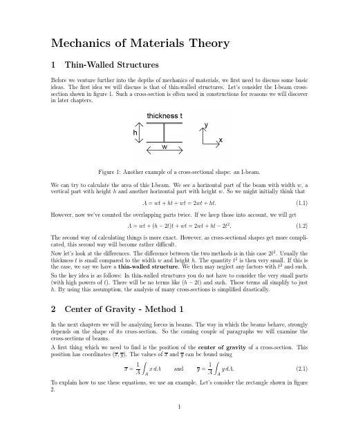
Lesson Two Introduction to Mechanics of MaterialsIn all engineering construction the component parts of a structure must be assigned definite physical sizes. Such parts must be properly proportioned to resist the actual or probable forces that may be imposed upon them. 在所有的工程构造中,结构的构件必须具有确定的实际尺寸。
这些构件必须比例适当,能够承受实际施加或可能施加于其上的力。
Thus, the walls of a pressure vessel must be of adequate strength to withstand the internal pressure; the floors of a building must be sufficiently strong for their intended purpose; the shaft of a machine must be of adequate size to carry the required torque; a wing of an airplane must safely withstand the aerodynamic loads which may come upon it in flight or landing. 这就是说,压力容器的壁必须具有足够的强度以承受其内部压力;建筑物的地面对其预期的设计载荷而言必须是足够坚固;机器的轴必须具有适当的尺寸才能传递所要求的扭矩,飞机的机翼必须能够安全地承受飞行或着陆时加在其上的空气动力荷载。
Likewise, the parts of a composite structure must be rigid enough so as not to deflect or “sag” excessively when in operation under the imposed loads.A floor of a building may be strong enough but yet may deflect excessively, which in some instances may cause misalignment of manufacturing equipment, or in other cases result in the cracking of a plaster ceiling attached underneath. 同样地,复合结构中的零件也必须具有足够的刚度,使其在外加载荷下工作时不致于有过大的变形或“下垂”。
材料力学双语教学学习资料第一章绪论Chapter 1 Introduction§1-1 材料力学的任务The Tasks of Mechanics of Materials1*. 材料力学: Mechanics of Materials2. 构件: Structural Members3. 变形: Deformation4*. 强度: Strength5*. 刚度: Rigidity6*. 稳定性: Stability§1-2 变形固体的基本假设Fundamental Assumptions of SolidDeformation Bodies1. 连续性假设: Continuity2. 均匀性假设: Homogeneity3. 各向同性假设: Isotropy§1.3 外力及其分类External Forces and Classification1. 分布力: Distributed Force2. 集中力: Point Force3. 静载荷: Static Load4. 动载荷: Dynamic Load§1.4 内力、截面法和应力的概念Concepts of Internal Forces,Method ofSection and Stress1*. 内力: Internal Force2*. 截面法: Method of Section3. 截面法的三个步骤:截开,代替,平衡Three steps of method of section: cut off, substitute , and equilibrium.4*. 应力: Stress5. 平均应力:Average stress6. 应力(全应力):Whole stress(sum stress)7*. 正应力: Normal Stress8*. 剪应力(切应力):Shearing Stress§1.5 变形与应变Deformation and Strain1.线应变: Strain2.剪应变: Shearing Strain§1.6 杆件变形的基本形式Basic Types of Deformations of Rods1*. 拉伸或压缩: Tension or Compression2*. 剪切: Shear3*. 扭转: Torsion4*. 弯曲: Bending第二章拉伸、压缩与剪切Chapter 2 Tension,Compression andShear§2.1 轴向拉伸与压缩的概念和实例The Concept and Examples of AxialTension and Compression1. 拉杆: Tensile Rod2. 压杆: Compressive Rod3. 受力特点:外力合力的作用线与杆轴线重合Characteristic of the External Forces: The acting line of the resultant of external forces is coincided with the axis of the rod.4. 变形特点:杆沿轴向伸长或缩短Characteristic of Deformation: Rod will elongate or contract along the axis of the rod.§2.2 轴向拉伸或压缩时横截面上的内力和应力Internal Force and Stress of Axial Tension or Compression on the Cross Section1*. 横截面: Cross Section2*. 轴力: Normal Force3*. 轴力图: Diagram of Normal Force§2.3 直杆轴向拉伸或压缩时斜截面上的应力Stress of Axial Tension or Compressionon the Skew Section1. 斜截面: Skew Section2.ασσα2cos = αστα2s i n 2=§2.4 材料在拉伸时的力学性能Mechanical Properties of Materialswith Tensile Load1. 标准试件: Specimen2. 低碳钢(C ≤0.3%): Low Carbon Steel3. 弹性阶段:Elastic Region4. 屈服阶段:Yielding Stage5. 强化阶段:Hardening Stage6. 颈缩阶段: Necking Stage 7*.σp ----比例极限: Proportional Limit 8*.σe ----弹性极限: Elastic Limit 9*.σs ----屈服极限: Yielding Stress 10*.σb ----强度极限: Ultimate Stress 11. 延伸率: Percent Elongation12. 断面收缩率: Percent Reduction of Area 13. 塑性材料: Ductile Materials 14. 脆性材料: Brittle Materials 15. 铸铁:Cast iron§2.7 失效、安全系数和强度计算 Failure, Safety factor and Strengthcalculation1*. 许用应力: Allowable Stress 2. 安全系数: Safety Factor 3*. 强度条件: Strength Condition][max σσ≤=AF N4*. 强度校核: Check strength][max σσ≤5*. 截面设计: Section design][σNF A ≥6*. 确定许可载荷:Determine allowable load][σA F N ≤§2.8 轴向拉伸或压缩时的变形 Deformation in Axial Tension orCompression1. 弹性变形: Elastic Deformation2. 塑性变形: Plastic Deformation3. 纵向应变: Longitudinal Strainll l l l -=∆=1ε 4. 横向应变: Lateral Straindd d d d -=∆=''ε5.线弹性变形:Linear Elastic Deformation6.泊松比:Poisson’s ratioεεμ'=7*.弹性模量-E :表示材料抵抗拉压变形的 能力 E - modulus of elasticity :Indicates the capability of materials for resisting tension or compression 8*.抗拉刚度-EA :表示构件抵抗拉压变形的能力EA -the axial rigidity: Indicates the capability of constructive members for resisting tension or compression 9*. 胡克定律(Hooke’s Law ):当应力不超过材料的比例极限时,应力与应变成正比.The stress is proportional to the strain within the elastic region.εσE =§2.12 应力集中的概念The Concept of Stress Concentration 1.由于截面尺寸的突然变化,使截面上的应力分布不再均匀,在某些部位出现远大于平均值的应力,称应力集中。
1Introduction1.1 What’s it aboutThis is a book about the Mechanics of Solids, Statics, the Strength of Materials, and Elasticity Theory. But that doesn’t mean a thing unless you have had a course in the Mechanics of Solids, Statics, the Strength of Materials, or Elasticity The-ory. I assume you have not; let us try again:This is a book that builds upon what you were supposed to learn in your basic physics and mathematics courses last year. We will talk about forces – not politi-cal, but vector forces – about moments and torques, reactions, displacements, lin-ear springs, and the requirements of static equilibrium of a particle or a rigid body. We will solve sets of linear algebraic equations and talk about when we can not find a unique solution to a set of linear algebraic equations. We will derive a whole raft of new equations that apply to particles, bodies, structures, and mecha-nisms;these will often contain the spatial derivatives of forces, moments, and dis-placements. You have seen a good bit of the basic stuff of this course before, but we will not assume you know the way to talk about, or work with, these concepts, principles, and methods so fundamental to our subject. So we will recast the basics in our own language, the language of engineering mechanics.For the moment, think of this book as a language text;of yourself as a lan-guage student beginning the study of Engineering Mechanics, the Mechanics of Solids, the Strength of Materials, and Elasticity Theory. You must learn the lan-guage if you aspire to be an engineer. But this is a difficult language to learn, unlike any other foreign language you have learned. It is difficult because, on the surface, it appears to be a language you already know. That is deceptive: You will have to be on guard, careful not to presume the word you have heard before bears the same meaning. Words and phrases you have already encountered now take on a more special and, in most cases, narrower meaning;a couple of forces is more than just two forces.An important part of learning the vocabulary, is the quick sketch. Along with learning to sketch in the engineering mechanics way, you will have to learn the meaning of certain icons;a small circle, for example, becomes a frictionless pin. So too, grammar and syntax will be crucial. Rigorous rules must be learned and obeyed. Some of these rules will at first seem pedantic;they may strike you as not only irrelevant to solving the problem, but wrong-headed or counter intuitive. But don’t despair; with use they will become familiar and reliable friends.When you become able to speak and respond in a foreign language without thinking of every word, you start to see the world around you from a new perspec-2 Chapter 1tive. What was once a curiosity now is mundane and used everyday, often without thinking. So too, in this course, you will look at a tree and see its limbs as cantile-ver beams, you will look at a beam and see an internal bending moment, you will look at a bending moment and conjecture a stress distribution. You will also be asked to be creative in the use of this new language, to model, to estimate, to design.That’s the goal: To get you seeing the world from the perspective of an engi-neer responsible for making sure that the structure does not fail, that the mecha-nism doesn’t make too much noise, that the bridge doesn’t sway in the wind, that the latch latches firmly, the landing gear do not collapse upon touchdown, the drive-shaft does not fracture in fatigue... Ultimately, that is what this book is about. Along the way you will learn about stress, strain, the behavior of trusses, beams, of shafts that carry torsion, even columns that may buckle.1.2 What you will be doing.The best way to learn a foreign language is from birth;but then it’s no longer a foreign language. The next best way to learn a new language is to use it – speak it, read it, listen to it on audio tapes, watch it on television;better yet, go to the land where it is the language in use and use it to buy a loaf of bread, get a hotel room for the night, ask to find the nearest post office, or if you are really proficient, make a telephone call. So too in the Mechanics of Solids, we insist you begin to use the language.Doing problems and exercises, taking quizzes and the final, is using the lan-guage. This book contains mostly exercises explained as well as exercises for you to tackle. There are different kinds of exercises, different kinds for the different contexts of language use.Sometimes an engineer will be asked a question and a response will be expected in five minutes. You will not have time to go to the library, access a data-base, check this textbook. You must estimate, conjure up a rational response on the spot. “....How many piano tuners in the city of Chicago?” (Try it)! Some of the exercises that follow will be labeled estimate.Often practicing engineers must ask what they need to know in order to tackle the task they have been assigned. So too we will ask you to step back from a prob-lem and pose a new problem that will help you address the original problem. We will label these exercises need to know.A good bit of engineering work is variation on a theme, changing things around, recasting a story line, and putting it into your own language for produc-tive and profitable use. Doing this requires experimentation, not just with hard-ware, but with concepts and existing designs. One poses “what if we make this strut out of aluminum... go to a cantilever support... pick up the load in bending?” We will label this kind of exercise what if?Engineering analysis (as well as prototype testing and market studies) is what justifies engineering designs. As an engineer you will be asked to show that your3Introductiondesign will actually work. More specifically, in the terms of this subject, you will be asked to show the requirements of static equilibrium ensure your proposed structure will bear the anticipated loading, that the maximum deflection of simply supported beam at midspan does not exceed the value specified in the contract, that the lowest resonant frequency of the payload is above 100 Hz. The show that. label indicates a problem where a full analysis is demanded. Most often this kind of problem will admit of a single solution – in contrast to the estimate, need to know,or even w hat if exercise. This is the form of the traditional textbook prob-lem set.Closely related to show that exercises, you will be asked to construct a response to questions, as in “construct an explanation explaining why the beam failed”, or “construct an expression for the force in member ab”. We could have used the ordinary language, “explain” or “derive” in these instances but I want to emphasize the initiative you, as learner, must take in explaining or deriving. Here, too, construct better reflects what engineers actually do at work.Finally, what engineers do most of the time is design, design in the broadest sense of the term;they play out scenarios of things working, construct stories and plans that inform others how to make things that will work according to their plans. These design exercises are the most open-ended and unconstrained exer-cises you will find in this text. We will have more to say about them later.In working all of these different kinds of exercises, we want you to use the lan-guage with others. Your one-on-one confrontation with a problem set or an exam question can be an intense dialogue but it’s not full use of the language. Your abil-ity to speak and think in the language of engineering mechanics is best developed through dialogue with your peers, your tutors, and your teacher. We encourage you to learn from your classmates, to collectively learn from each other’s mis-takes and questions as well as problem-solving abilities.Exercise 1.1 An Introductory ExerciseAnalyse the behavior of the mechanism shown in the figure. That is, deter-mine how the deflection, ∆, of point B varies as the load, P, varies.4 Chapter 1This exercise is intended to introduce the essential concepts and principles of the engineering mechanics of solids. It is meant as an overview;do not be disturbed by the variety of concepts or range of vocabulary. We will try to grasp the essen-tial workings of the device and begin to see the relevance of the concepts and principles of engineering mechanics to an understanding of how it functions and how it might be made to work betterWe will apply the requirements of static equilibrium. We will analyze the dis-placements of different points of the structure, e.g., the vertical displacement of point B and the horizontal displacements of points A and C, and make sure these are compatible. We will consider the deformation of the springs which connect points A and C to ground and posit a relationship between the force each one bears and the relative displacement of one end with respect to the other end. We will assume this force/deformation relationship is linear.We will learn to read the figure; k is the constant of proportionality in the equation relating the force in the spring to its deformation;the little circles are frictionless pins, members AB and BC are two-force members — as straight mem-bers they carry only tension and compression. The grey shading represents rigid ground. The arrow represents a vertically applied load whose magnitude is “P”.Our aim is to determine the behavior of the structure as the applied load increases from zero to some or any finite value. In particular, we want to deter-mine how ∆ varies as P changes. We will use a spread sheet to make a graph of this relationship — but only after setting up the problem in terms of non-dimen-sional expressions for the applied load, P, the vertical displacement, ∆, and the horizontal displacement, u. We will allow for relatively large displacements and rotations. We will investigate the possibility of snap-through, a type of instability, if P gets too large. In sum, our objective is to determine how the applied load P varies with ∆, or, alternatively, for any prescribed ∆, what P need be applied?We will discuss how this funny looking linkage of impossible parts (friction-less pins, rollers, rigid grey matter, point loads, ever linear springs) can be a use-ful model of real-world structures. There is much to be said;all of this italicized language important.We start by reasoning thus:Clearly the vertical displacement, ∆, is related to the horizontal displacements of points A and C;as these points move outward, point B moves downward. We assume our system is symmetric; the figure suggests this;if A moves out a dis-tance u, C displaces to the right the same distance. Note: Both u and ∆ are mea-sured from the undeformed or unloaded configuration, P, ∆ =0 . (This undeformend configuration is indicated by the dashed lines and the angle Θ0 ).As P increases, ∆ increases and so too u which causes the springs to shorten. This engenders a compressive force in the springs and in the members AB and BC, albeit of a different magnitude, which in turn, ensures static equilibrium of the system and every point within it including the node B where the load P is applied. But enough talk;enough story telling. We formulate some equations and try to solve them.5IntroductionStatic Equilibrium of Node B.The figure at the right shows anisola-Ption of node B. It is a free body diagram;i.e., the node has been cut free of all thatsurrounds it and the influence of those sur-roundings have been represented by forces.The node is compressed by the force, F,ofisground. It is vertical since the rollers signifythat there is no resistance to motion in the hori-zontal direction;there is no friction. f s is the compressive force in the spring, again, pressing on the node C.Equilibrium requires that the resultant of the three forces vanish. Requiring that the sum of the horizontal components and that the sum of the vertical compo-nents vanish independently will ensure that the vector sum, which is the resultant, will vanish. This yields two scalar equations:F ⋅ cos θ – f = 0 and R F⋅ sin θ=0–sThe first ensures equilibrium in the horizontal direction, the second, in the vertical direction.Force/Deformation of the spring:For our linear spring, we can write:f = k u⋅sThe force is proportional to deformation.6 Chapter 1Compatibility of Deformation:∆ and Θ are not independent;you can not choose one arbitrarily, then the other arbitrarily. The first figure indicates that, if members AB and BC remain continu-ous and rigid1, we haveu = L( cos θ – cos θ0 )But we want ∆, ultimately. Another compatibility relationship is seen to be∆ = L( sin θ0– sin θ)Solution: The relation between P and ∆.From equilibrium of node B we have an equation for F, the compressive force in members AB and BC in terms of P and θ; Using our result obtained from equi-librium of node C, we can express the force in the spring, f s in terms of P and θ.f = (P ⁄ 2)( cos θ⁄ sin θ)sFrom the force/deformation relationship for the spring we express, u, the dis-placement of the node C (and A) in terms of f s, and, using the immediately above, in terms of P and θ.u = f ⁄ k = (P ⁄ 2k )( cos θ⁄ sin θ)sThe first compatibility relationship then allows us to write(P ⁄ 2kL) = sin θ⋅(1– cos θ0 ⁄ cos θ)while the second may be written in non-dimensional form as∆⁄ L = sin θ0– sin θWe could at this point try to eliminate theta; but this is unnecessary. This parametric form of the relationship between P and ∆ will suffice. Theta serves as an intermediary -a parameter whose value we can choose -guided by our sketch of the geometry of our structure. For each value of theta, the above two equations then fix the value of the vertical displacement and the applied load. A spread sheet is an appropriate tool for carrying out a sequence of such calculations and for constructing a graph of the way P varies with ∆, which is our objective. This is left as an exercise for the reader.1. They neither lengthen nor contract when loaded.7Introduction1.3 Resources you may use.A textbook is only one resource available to you in learning a new language. The exercises are another, pehaps the most important other resource you have avail-able. Still others are the interactive short simulations – computer representations of specific problems or phenomena – made available to you over the web. You will find there as well more sophisticated and generally applicable tools which will enable you to model truss and frame structures -structures which have many members. Another more standard and commonly available tool is the spreadsheet. You will find all these modeling tools to be essential and powerful aids when con-fronted with an open-ended design exercise where the emphasis is on what if and show that.Another resource to you is your peers. We expect you to learn from your class-mates, to collaborate with them in figuring out how to set up a problem, how to use a spreadsheet, where on the web to find a useful reference. Often you will be asked to work in groups of two or three, in class -especially when a design exer-cise is on the table -to help formulate a specification and flesh out the context of the exercise. Yet your work is to be your own.8 Chapter 11.4 Problems1.1 Without evaluating specific numbers, sketch what you think a plot of the load P -in nondimensional form -(P/2kL) versus the displacement, (∆/L) will look like for the Introductory Exercise above. Consider θ to vary over the interval Θ0 ≥Θ≥ –Θ0 .Now compute, using a spread sheet, values for load and displacement and plot over the same range of the parameter Θ.。