
CD-ROM 0060 - 1Revision 0
December 1996
METHOD 0060DETERMINATION OF METALS IN STACK EMISSIONS
1.0SCOPE AND APPLICATION
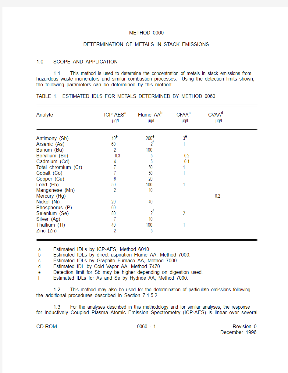
1.1This method is used to determine the concentration of metals in stack emissions from
hazardous waste incinerators and similar combustion processes. Using the detection limits shown,
the following parameters can be determined by this method:
TABLE 1. ESTIMATED IDLS FOR METALS DETERMINED BY METHOD 0060
Analyte ICP-AES
Flame AA GFAA CVAA a b c d μg/L
μg/L μg/L μg/L Antimony (Sb)
40 200 3e e e Arsenic (As)
60 2 1f Barium (Ba) 2 100Beryllium (Be)
0.3 5 0.2Cadmium (Cd) 4 5 0.1Total chromium (Cr) 7
50 1Cobalt (Co) 7
50 1Copper (Cu) 6
20Lead (Pb) 50
100 1Manganese (Mn) 2
10Mercury (Hg) 0.2Nickel (Ni) 20
40Phosphorus (P) 60
Selenium (Se) 80
2 2f Silver (Ag) 7
10Thallium (Tl)
40
100 1Zinc (Zn) 2 5 a
Estimated IDLs by ICP-AES, Method 6010. b
Estimated IDLs by direct aspiration Flame AA, Method 7000. c
Estimated IDLs by Graphite Furnace AA, Method 7000. d
Estimated IDL by Cold Vapor AA, Method 7470. e
Detection limit for Sb may be higher depending on digestion used. f Estimated IDLs for As and Se by Hydride AA, Method 7000.
1.2This method may also be used for the determination of particulate emissions following
the additional procedures described in Section 7.1.5.2.
1.3For the analyses described in this methodology and for similar analyses, the response
for Inductively Coupled Plasma Atomic Emission Spectrometry (ICP-AES) is linear over several
orders of magnitude. Samples containing metal concentrations in the micrograms per liter (μg/L) to milligrams per liter (mg/L) range in the final analytical solution can be analyzed using this technique. Samples containing greater than approximately 50 mg/L of chromium, lead, or arsenic should be diluted to that level or lower for final analysis. Samples containing greater than approximately 20 mg/L of cadmium should be diluted to that level before analysis.
1.4The actual method detection limits are sample dependent and may vary as the sample matrix affects the limits. Method detection limits for antimony can also be dependent on the digestion method used and may be considerably higher than the estimated detection limits. Method detection limits for all analytes may differ from the estimated detection limits when hydrofluoric acid digestion is used. For more information on MDLs, refer to Chapter One.
1.5The complexity of this methodology is such that to obtain reliable results, the testers (including analysts) should be experienced and as knowledgeable as required in source sampling, in handling and preparing (including mixing) reagents as discussed, and in using adequate safety procedures and protective equipment. The experience and knowledge should assure adequacy as described above in all of the source emission determination activities including planning of the desired detection limits.
2.0SUMMARY
2.1The stack sample is withdrawn isokinetically from the source. Particulate emissions are collected in the probe and on a heated filter and gaseous emissions are collected in a series of chilled impingers as shown in Figure 1 and described in Section 4.1.6. Two impingers are empty, two impingers contain an aqueous solution of dilute nitric acid combined with dilute hydrogen peroxide, two other impingers contain acidic potassium permanganate solution, and the last impinger contains a desiccant.
2.2Sampling train components are recovered and digested in separate front-half and back-half fractions. Materials collected in the sampling train are acid digested to dissolve inorganics and to remove organic constituents that may create analytical interferences. Acid digestion is performed by using either digestion techniques of this manual, or the Method 29 (Ref. 3) procedures.
2.3The nitric acid and hydrogen peroxide impinger solution, the hydrochloric acid rinse solution, the acidic potassium permanganate impinger solution, and the probe rinse and digested filter solutions are analyzed for mercury by Cold Vapor Atomic Absorption Spectrometry (CVAA). All of the sampling train catches, except for the permanganate solution, hydrochloric acid rinse solutions, and reagent water used to recover Hg, may be analyzed for target metals as presented in Table 1 by Inductively Coupled Plasma - Atomic Emission Spectrometry (ICP-AES) or Flame Atomic Absorption Spectrometry (FLAA). Similarly, Inductively Coupled Plasma-Mass Spectrometry (ICP-MS) may be used for analysis of Sb, As, Ba, Be, Cd, Cr, Co, Cu, Pb, Mn, Ni, As, Tl and Zn. If antimony, arsenic, beryllium, cadmium, chromium, cobalt, lead, selenium, and thallium require greater analytical sensitivity than can be obtained by ICP-AES, then Graphite Furnace Atomic Absorption Spectrometry (GFAA) is used for the analysis. Additionally, if desired, the tester may use FLAA for analyses of all metals if the resulting in-stack method detection limits meet the goal of the testing program.
2.4For convenience, aliquots of each digested sample Fraction 1A, as described in Section 7.2.
3.2, plus Fraction 2A, as described in Section 7.2.4, can be combined for a single CD-ROM0060 - 2Revision 0
December 1996
CD-ROM 0060 - 3Revision 0
December 1996
analytical determination, proportionally with respect to the original Fractions 1A and 2A. Fraction 1A
is normally diluted to 300 mL following digestion prior to analysis and the concentrated Fraction 2A
is normally diluted to 150 mL following digestion and prior to analysis.
2.5The efficiency of the analytical procedure is quantified by the analysis of spiked quality
control samples containing each of the target metals and/or other quality assurance measures as
described in Section 8.0 of this method including actual sample matrix effects checks.
3.0INTERFERENCES
3.1Refer to the appropriate determinative method for instructions on minimization of
interferences.
4.0APPARATUS AND MATERIALS
4.1Sampling train - A schematic of the sampling train is shown in Figure 1. It is similar
to the Method 5 (Ref. 3) train. The sampling train consists of the following components.
4.1.1Probe nozzle (probe tip) and borosilicate or quartz glass probe liner - Same
as Method 5, except that glass nozzles are required unless an alternate probe tip prevents
the possibility of contamination or interference of the sample with its materials of
construction. If a probe tip other than glass is used, no correction of the stack sample test
results can be made because of the effect on the results by the probe tip.
4.1.2Pitot tube and differential pressure gauge - Same as Method 2 (Ref. 3).
4.1.3Filters - Quartz fiber or glass fiber filters without organic binders shall be used.
The filters shall contain less than 1.3 μg/in. of each of the metals to be measured.
2Analytical results provided by filter manufacturers are acceptable. However, if no such
results are available, filter blanks must be analyzed for each target metal prior to emission
testing. The filters should exhibit at least 99.95 percent efficiency (<0.05 percent
penetration) on 0.3 micron dioctyl phthalate smoke particles. The filter efficiency test should
be conducted in accordance with ASTM Standard Method D2986-71 (Reference 4). For
particulate determination in sources containing SO or SO , the filter material must be of a
2 3type that is unreactive to SO or SO , as described Method 5. Quartz fiber filters that meet
2 3these requirements are recommended.
4.1.4Filter holder - Glass, same as Method 5, except that a Teflon filter support or
other non-metallic, non-contaminating support must be used to replace the glass frit.
4.1.5
Filter heating system - Same as Method 5.4.1.6Condenser
4.1.6.1 The following system shall be used for the condensation and
collection of gaseous metals and for determining the moisture content of the stack
gas. The condensing system should consist of three to seven impingers connected
in series with leak-free ground glass fittings or other leak-free, non-contaminating
fittings. Teflon impingers of substantially the same shape, size and function
CD-ROM 0060 - 4Revision 0
December 1996
compared to the glass impingers and connected with leak-free non-contaminating
fittings may be used: - additionally, the distance from the bottom of the gas conduit
stem of the Teflon impinger assembly to the bottom of the portion of the impinger
assembly which holds the aqueous acidic solutions must meet the same distance
requirements as the glass impingers. The first impinger is optional and is
recommended as a moisture knockout trap for use during test conditions which
require such a trap. The first impinger shall be empty. The second and third
impingers shall contain known quantities of a nitric acid/hydrogen peroxide solution
(Section 5.8). The fourth shall be empty. The fifth and sixth impingers shall contain
a known quantity of acidic potassium permanganate solution (Section 5.12), and the
last impinger shall contain a known quantity of silica gel or equivalent desiccant. A thermometer capable of measuring to within 1C (2
F) shall be placed at the outlet o o of the last impinger.
4.1.6.2 The first impinger shall be appropriately sized for a potentially large
moisture catch and constructed generally as described for the first impinger in
Method 5. The second impinger (or the first HNO /H O impinger) shall also be as
322described for the first impinger in Method 5. The third impinger (or, in any case, the
impinger used as the second HNO /H O impinger) shall be the same as the
322Greenburg-Smith impinger with the standard tip described as the second impinger
in Method 5. All other impingers used in the metals train are the same as the first
HNO /H O impinger.
3224.1.6.3 Based on the specific source sampling conditions, the use of an
empty first impinger can be eliminated if the moisture to be collected in the impingers
will be less than approximately 100 mL. When the moisture knockout impinger is not
needed, it is removed from the train and the other impingers remain the same. If
mercury analysis is not to be performed, the potassium permanganate impingers and
the empty impinger preceding them are removed.
4.1.7Metering system, barometer, and gas density determination equipment -
Same as Method 5.
4.1.8Teflon tape - For capping openings and sealing connections, if necessary, on
the sampling train.
4.2Sample recovery. Same as Method 5, with the following exceptions and additions:
4.2.1Non-metallic probe-liner and probe-nozzle brushes or swabs - For quantitative
recovery of materials collected in the front half of the sampling train. Description of
acceptable all-Teflon component brushes or swabs to be included in EPA's Emission
Measurement Technical Information Center (EMTIC) files.
4.2.2Sample storage containers - Glass bottles, 1000 mL and 500 mL, with Teflon-
lined caps which are non-reactive to oxidizing solutions, shall be used for samples and
blanks containing KMnO . Polyethylene bottles may be used for other sample types.
44.2.3Polypropylene tweezers and/or plastic gloves - For recovery of the filter from
the sampling train filter holder.
CD-ROM 0060 - 5Revision 0
December 1996
4.3Sample preparation and analysis equipment.
4.3.1Refer to the appropriate preparation and analytical techniques for the proper
apparatus and materials. Refer to Section 7.2 for a description of preparation techniques.
5.0REAGENTS
5.1 Reagent grade inorganic chemicals shall be used in all tests. Unless otherwise
indicated, it is intended that all reagents conform to the specifications established by the Committee
on Analytical Reagents of the American Chemical Society, where such specifications are available.
Otherwise use the best available grade.
5.2Reagent Water. Refer to Chapter One for a definition of reagent water. Analyze the
water for all target metals prior to field use. All target metals should be less than the MDL.
5.3Nitric acid, concentrated - Baker Instra-analyzed or equivalent.
5.4Nitric acid (0.1 M) - Add, with stirring,
6.3 mL of concentrated HNO to a flask
3containing approximately 900 mL of water. Dilute to 1000 mL with water. Mix well. The reagent
shall contain less than 2 μg/L of each target metal.
5.5Nitric acid, 10 percent (V/V). Add, with stirring, 500 mL of concentrated HNO to a
3flask containing approximately 4000 mL of water. Dilute to 5000 mL with water. Mix well. Reagent
shall contain less than 2 μg/L of each target metal.
5.6Nitric acid, 5 percent (V/V). Add, with stirring, 50 mL of concentrated HNO to 800
3mL of water. Dilute to 1000 mL with water. Reagent shall contain less than 2 μg/L of each target
metal.
5.7Nitric acid, 50 percent (V/V). Add, with stirring, 125 mL of concentrated HNO to a
3flask containing approximately 100 mL of water. Dilute to 250 mL with water. Mix well. Reagent
shall contain less than 2 μg/L of each target metal.
5.8Nitric acid (HNO )/hydrogen peroxide (H O ) absorbing solution, 5 percent HNO /10
3 22 3percent H O . Add carefully, with stirring, 50 mL of concentrated HNO to a 1000-mL volumetric
22 3flask containing 500 mL of water. Carefully add 333 mL of 30% H O to the flask. Dilute to volume
22with water. The reagent shall contain less than 2 μg/L of each target metal.
5.9Hydrochloric acid (8M), HCl - Carefully add with stirring 690 mL of concentrated HCl
to a flask containing 250 mL of water. Dilute to 1000 mL with water. Mix well. The reagent shall
contain less than 2 μg/L of Hg.
5.10
Hydrogen peroxide, 30 percent (V/V).5.11Potassium permanganate, 5 percent (W/V).
5.12Acidic potassium permanganate (KMnO ) absorbing solution, 4 percent KMnO (W/V),
4 410 percent H SO (V/V) - Prepare fresh daily. Carefully mix 100 mL of concentrated H SO into 800
24 24mL of water. Add water, with stirring, to make a volume of 1000 mL. This solution is 10% H SO 24
CD-ROM 0060 - 6Revision 0
December 1996
(V/V). Dissolve, with stirring, 40 g of KMnO into sufficient 10% H SO to make a volume of 1 liter.
4 24Prepare and store in glass bottles to prevent degradation. The reagent shall contain less than 2 μg/L
of Hg.CAUTION: To prevent autocatalytic decomposition of the permanganate solution, filter the
solution through Whatman 541 filter paper. Also, due to reaction of the potassium
permanganate with the acid, there may be pressure buildup in the sample storage bottle;
these bottles should not be fully filled and should be vented both to relieve excess pressure
and prevent explosion due to pressure buildup. Venting is highly recommended, but should
not allow contamination of the solution; a No. 70-72 hole drilled in the container cap and
Teflon liner is suggested.
5.13
Sulfuric acid, concentrated.5.14
Silica gel and crushed ice - Same as Method 5.5.15Hydrofluoric acid, concentrated.
5.16Refer to the appropriate preparation and analytical technique for reagent and standard
preparation procedures.
6.0SAMPLE COLLECTION, PRESERVATION, AND HANDLING
6.1Sampling. The complexity of this method is such that, to obtain reliable results,
testers should be trained and experienced with the test procedures.
6.1.1Pretest preparation. Follow the same general procedure given in Method 5,
except that, unless particulate emissions are to be determined, the filter need not be
desiccated or weighed. All sampling train glassware should first be rinsed with hot tap water
and then washed in hot soapy water. Next, glassware should be rinsed three times with tap
water, followed by three additional rinses with reagent water. All glassware should then be
soaked in a 10% (V/V) nitric acid solution for a minimum of 4 hours, rinsed three times with
reagent water, rinsed a final time with acetone, and allowed to air dry. All glassware
openings where contamination can occur should be covered until the sampling train is
assembled, prior to sampling.
6.1.2Sampling train calibration. Maintain a laboratory log of all calibrations.
Calibrate the sampling train components according to the appropriate sections of Method 5:
probe nozzle; pitot tube; metering system; probe heater; temperature gauges; leak-check of
the metering system; and barometer.
6.1.3
Preliminary determinations. Same as Method 5.6.1.4Preparation of Sampling Train.
6.1.4.1 Follow the same general procedures given in Method 5, except place
100 mL of the nitric acid/hydrogen peroxide solution (Section 5.8) in each of the two
HNO /H O impingers (normally the second and third impingers) as shown in Figure
3221. Place 100 mL of the acidic potassium permanganate absorbing solution (Section
5.12) in each of the two permanganate impingers. Transfer approximately 200 to 300
g of preweighed silica gel from its container to the last impinger. Alternatively, the
silica gel may be weighed directly in the impinger just prior to train assembly.
6.1.4.2 Several options are available to the tester based on the sampling
conditions. The empty first impinger is not needed if the moisture to be collected in
the impingers is calculated or determined to be less than 100 mL.
6.1.4.3 Retain for reagent blanks, volumes of the nitric acid/hydrogen
peroxide solution and 100 mL of the acidic potassium permanganate solution. These
reagent blanks should be labeled and analyzed as described in Section 7. Set up the
sampling train as shown in Figure 1. If necessary to ensure leak-free sampling train
connections, Teflon tape or other non-contaminating material should be used instead
of silicone grease to prevent contamination.
CAUTION: Extreme care should be taken to prevent contamination within the
train. Prevent the mercury collection reagent (acidic potassium
permanganate) from contacting any glassware of the train which is washed
and analyzed for manganese. Prevent hydrogen peroxide from mixing with
the acidic potassium permanganate.
6.1.4.4 Alternatively, mercury emissions can be measured in a separate
train which measures only mercury emissions by using Method 101A (use only the
version of Method 101A which incorporates the changes promulgated on April 25,
1996, in 61 FR 18278 through 18280, or later).
6.1.5Leak-check procedures. Follow the leak-check procedures given in Method
5: pretest leak-check, leak-checks during the sample run, and post-test leak-checks.
6.1.6Sampling train operation. Follow the procedures given in Method 5. For each
run, record the data required on a data sheet such as the one shown in Figure 5-2 of Method
5. When sampling for Hg, use a procedure analogous to that described in Section 7.1.1 of
Method 101A, 40 CFR Part 61, Appendix B, if necessary to maintain the desired color in the last acidified permanganate impinger.
6.1.7Calculation of percent isokinetic. Same as Method 5.
7.0PROCEDURE
7.1Sample recovery. Begin cleanup procedures as soon as the probe is removed from the stack at the end of a sampling period.
7.1.1The probe should be allowed to cool prior to sample recovery. When it can
be safely handled, wipe off all external particulate matter near the tip of the probe nozzle and place a rinsed, non-contaminating cap over the probe nozzle to prevent losing or gaining particulate matter. Do not cap the probe tip tightly while the sampling train is cooling. This normally causes a vacuum to form in the filter holder, thus causing the undesired result of drawing liquid from the impingers into the filter.
CD-ROM0060 - 7Revision 0
December 1996
7.1.2Before moving the sampling train to the cleanup site, remove the umbilical
cord from the last impinger and cap the impinger. Cap off the filter holder outlet and impinger inlet. Use non-contaminating caps, whether ground-glass stoppers, plastic caps, serum caps, or Teflon tape to close these openings.
7.1.3Alternatively, the train can be disassembled before the probe and filter
holder/oven are completely cooled, if this procedure is followed: Initially disconnect the filter holder outlet/impinger inlet and loosely cap the open ends. Then disconnect the probe from the filter holder or cyclone inlet and loosely cap the open ends. Cap the probe tip and remove the umbilical cord as previously described.
7.1.4Transfer the probe and filter-impinger assembly to a cleanup area that is clean
and protected from the wind and other potential causes of contamination or loss of sample.
Inspect the train before and during disassembly and note any abnormal conditions.
7.1.5The sample is recovered and treated as follows (see schematic in Figure 2).
Assure that all items necessary for recovery of the sample do not contaminate it.
7.1.5.1 Container No. 1 (filter). Carefully remove the filter from the filter
holder and place it in its identified petri dish container. Acid-washed polypropylene
or Teflon coated tweezers or clean disposable surgical gloves rinsed with water
should be used to handle the filters. If it is necessary to fold the filter, make certain
the particulate cake is inside the fold. Carefully transfer the filter and any particulate
matter or filter fibers that adhere to the filter holder gasket to the petri dish by using
a dry (acid-cleaned) nylon bristle brush. Do not use any metal-containing materials
when recovering this train. Seal the labeled petri dish.
NOTE: Follow the procedure in Section 7.1.5.2 only if determination of particulate
emissions are desired in addition to metals emissions. If only metals emissions are
to be determined, skip Section 7.1.5.2 and go to Section 7.1.5.3.
7.1.5.2 Container No. 2 (acetone rinse).
7.1.5.2.1 Taking care to see that dust on the outside of the probe or
other exterior surfaces does not get into the sample, quantitatively recover
particulate matter and any condensate from the probe nozzle, probe fitting
(fittings made of plastic such as Teflon, polypropylene, etc. are recommended
to prevent contamination by metal fittings, further, if desired a single glass
piece may be used, but it is not a requirement of this methodology), probe
liner, and front half of the filter holder by washing these components with 100
mL of acetone and placing the wash in a glass container. The use of exactly
100 mL is necessary for the subsequent blank correction procedures.
Reagent water may be used instead of acetone when approved by the
Administrator and shall be used when specified by the Adminstrator; in these
cases, save a water blank and follow the Administrators directions on
analysis. In these cases, save a water blank. Perform the acetone rinses as
follows: Carefully remove the probe nozzle and clean the inside surface by
rinsing with acetone from a wash bottle and brushing with a non-metallic
brush. Brush until the acetone rinse shows no visible particles, after which CD-ROM0060 - 8Revision 0
December 1996
make a final rinse of the inside surface with acetone. Brush and rinse the
sample exposed inside of the Swagelok fitting with acetone in a similar way
until no visible particles remain.
7.1.5.2.2 Rinse the probe liner with acetone by tilting and rotating the
probe while squirting acetone into its upper end so that all inside surfaces will
be wetted with acetone. Allow the acetone to drain from the lower end into
the sample container. A funnel may be used to aid in transferring liquid
washings to the container. Follow the acetone rinse with a nonmetallic probe
brush. Hold the probe in an inclined position, squirt acetone into the upper
end as the probe brush is being pushed with a twisting action through the
probe; hold a sample container underneath the lower end of the probe, and
catch any acetone and particulate matter which is brushed through the probe.
Rinse and brush three times or more until no visible particulate matter is
carried out with the acetone or until none remains in the probe liner on visual
inspection. Rinse the brush with acetone, and quantitatively collect these
washings in the sample container. After the brushing, make a final acetone
rinse of the probe as described above.
7.1.5.2.3 It is recommended that two people clean the probe to
minimize sample losses. Between sampling runs, keep brushes clean and
protected from contamination.
7.1.5.2.4 Clean the inside of the front half of the filter holder by
rubbing the surfaces with a nylon bristle brush and rinsing with acetone.
Rinse each surface three times or more if needed to remove visible
particulate. Make a final rinse of the brush and filter holder. Make a final
rinse of the brush and filter holder. After all acetone washings and particulate
matter have been collected in the sample container, tighten the lid on the
sample container so that acetone will not leak out when it is shipped to the
laboratory. Mark the height of the fluid level to determine whether or not
leakage occurred during transport. Label the container clearly to identify its
contents.
7.1.5.3 Container No. 3 (probe rinse). Keep the probe assembly clean and
free from contamination as described in Section 7.1.5.2 during the 0.1M nitric acid
rinse described below. Rinse the probe liner, probe nozzle, and filter, and front half
of the filter holder thoroughly with 100 mL of 0.1 M nitric acid and place the wash into
a sample storage container.
NOTE: The use of exactly 100 mL is necessary for the subsequent blank correction
procedures. Perform the rinses as applicable and generally as described in Method
12, Section 5.2.2. Record the volume of the combined rinse. Mark the height of the
fluid level on the outside of the storage container and use this mark to determine if
leakage occurs during transport. Seal the container and clearly label the contents.
Finally, rinse the nozzle, probe liner, and front half of the filter holder with water
followed by acetone and discard these rinses.
CD-ROM0060 - 9Revision 0
December 1996
CD-ROM 0060 - 10Revision 0
December 1996
7.1.5.4 Container No. 4 (Impingers 1 through 3, HNO /H O impingers and moisture
322knockout impinger, when used, contents and rinses). Due to the potentially large quantity
of liquid involved, the tester may place the impinger solutions from Impingers 1, 2, and 3 in
more than one container. Measure the liquid in the first three impingers volumetrically to
within 0.5 mL using a graduated cylinder or weigh quantitatively to 0.5 g using calibrated
scales. Record the volume of liquid present. This information is required to calculate the
moisture content of the sampled flue gas. Clean each of the first three impingers, the filter
support, the back half of the filter housing, and connecting glassware by thoroughly rinsing
with 100 mL of 0.1 M nitric acid using the procedure as applicable and generally as described
in Method 12, Section 5.2.4.NOTE: The use of exactly 100 mL of 0.1 M nitric acid rinse is necessary for the
subsequent blank correction procedures. Combine the rinses and impinger solutions,
measure and record the volume. Mark the height of the fluid level on outside of
container to determine if leakage occurs during transport. Seal the container and
clearly label the contents.
7.1.5.5 Containers No. 5A (0.1M HNO ), 5B (KMnO /H SO absorbing solution), and
3 4245C (8M HCl rinse and dilution). If mercury is not being measured in this train, then Impingers
4, 5, and 6, as shown in Figure 1, are not necessary and may be eliminated.
7.1.5.5.1 Pour all the liquid, if any, from the impinger which was empty at the
start of the run (normally Impinger 4) and which precedes the two permanganate
impingers into a graduated cylinder and measure the volume to within 0.5 mL. This
information is required to calculate the moisture content of the sampled flue gas.
Place the liquid in Sample Container No. 5A. Rinse the impinger (No. 4) with 100 mL
of 0.1M HNO and place this into Container No. 5A. Pour all the liquid from the two
3permanganate impingers into a graduated cylinder and measure the volume to within
0.5 mL. This information is required to calculate the moisture content of the sampled
flue gas. Place this KMnO absorbing solution stack sample from the two
4permanganate impingers into Container No. 5B. Using 100 mL total of the fresh
acidified potassium permanganate solution, rinse the permanganate impinger and
connecting glass pieces a minimum of three times. Place the rinses into Container
No. 5B, carefully assuring transfer of all loose precipitated materials from the two
impingers into Container No. 5B. Using 100 mL total of water, rinse the
permanganate impingers and connecting glass pieces a minimum of three times, and
place the rinses into Container No. 5B, carefully assuring transfer of all loose preci-
pitated material, if any, from the two impingers into Container No. 5B. Mark the
height of the fluid level on the outside of the bottle to determine if leakage occurs
during transport. See the following note and properly prepare the bottle and clearly
label the contents.NOTE: Due to the potential reaction of the potassium permanganate with the acid,
there may be pressure buildup in the sample storage bottle. These bottles shall not
be filled full and shall be vented to relieve excess pressure. Venting is required. A
No. 70-72 hole drilled in the container cap and Teflon liner is suggested.
7.1.5.5.2 If no visible deposits remain after the above described water rinse,
do not rinse with HCl. The previous rinses are designed to remove all of the
permanganate residues, but if any remain, perform the HCl cleanup in a well
ventilated area or vent hood as necessary to prevent exposure to any chlorine gases
which may be released by the following HCl cleanup procedure. If deposits do
remain on the glassware after this water rinse, wash the impinger surfaces with 25
mL of 8M HCl, and place the wash in a separate sample container labeled Container
No. 5C that contains 200 mL of water. Wash the impinger walls and stem with the
HCl by turning the impinger on its side and rotating it so that the HCl contacts all
inside surfaces. Use a total of only 25 mL of 8M HCl for rinsing both permanganate
impingers combined. Rinse the first impinger, then pour the actual rinse used for the
first impinger into the second impinger for its rinse. Finally, pour the 25 mL of 8M HCl
rinse carefully with stirring into Container No. 5C. Mark the height of the fluid level
on the outside of the bottle to determine if leakage occurs during transport.
7.1.5.6 Container No. 6 (silica gel). Note the color of the indicating silica gel to
determine whether it has been completely spent and make a notation of its condition.
Transfer the silica gel from its impinger to its original container and seal. The tester may use
a funnel to pour the silica gel and a rubber policeman to remove the silica gel from the
impinger. The small amount of particles that may adhere to the impinger wall need not be removed. Do not use water or other liquids to transfer the silica gel since weight gained in the silica gel impinger is used for moisture calculations. Alternatively, if a balance is available in the field, record the weight of the spent silica gel (or silica gel plus impinger) to the nearest 0.5g.
7.1.5.7 Container No. 7 (acetone blank). If particulate emissions are to be
determined, at least once during each field test, place 100-mL portion of the acetone used in the sample recovery process into a labeled container for use in the front-half field reagent blank. Seal the container.
7.1.5.8 Container No. 8A (0.1 M nitric acid blank). At least once during each field
test, place 300 mL of the 0.1 M nitric acid solution used in the sample recovery process into
a labeled container for use in the sample recovery process into a labeled container for use
in the front-half and back-half field reagent blanks. Seal the container.
7.1.5.9 Container No. 8B (water blank). At least once during each field test, place
100 mL of the water used in the sample recovery process into a labeled Container No. 8B.
Seal the container.
7.1.5.10 Container No. 9 (5 percent nitric acid/10 percent hydrogen peroxide blank).
At least once during each field test, place 200 mL of the 5% nitric acid/10% hydrogen peroxide solution used as the nitric acid impinger reagent into a labeled container for use in the back-half field reagent blank. Seal the container.
7.1.5.11 Container No. 10 (acidified potassium permanganate blank). At least once
during each field test, place 100 mL of the acidified potassium permanganate solution used as the impinger solution and in the sample recovery process into a labeled container for use in the back-half field reagent blank for mercury analysis. Prepare the container as described in Section 7.2.5.5.1 note.
CD-ROM0060 - 11Revision 0
December 1996
CD-ROM 0060 - 12Revision 0
December 1996
7.1.5.12 Container No. 11 (8M HCl blank). At least once during each field test, place
200 mL of water into a sample container. Then pour 25 mL of 8M HCl carefully with stirring
into the 200 mL of water in the container. Mix well and seal the container.
7.1.5.13 Container No. 12 (filter blank). Once during each field test, place an unused
filter from the same lot as the sampling filters in a labeled petri dish. Seal the petri dish.
This will be used in the front-half field reagent blank.
7.2Sample preparation. Note the level of the liquid in each of the containers and confirm
on the analysis sheet whether or not leakage occurred during transport. If a noticeable amount of
leakage has occurred either void the sample or use approved methods to correct the final results.
A diagram illustrating sample preparation and analysis procedures for each of the sample train
components is shown in Figure 3. If the sampling train uses an optional cyclone, the cyclone catch
should be prepared and digested using the same procedures described for the filters and combined
with the digested filter samples. Acid digestion is performed by using either prescribed digestion
techniques of this manual, or the Method 29 procedures.
7.2.1 Container No. 1 (filter). If particulate emissions are being determined, then desiccate
the filter and filter catch without added heat and weigh to a constant weight as described in Section
4.3 of Method
5. For analysis of metals, divide the filter with its filter catch into portions containing
approximately 0.5 g each and place into the analyst's choice of either individual fluorocarbon based
microwave pressure relief vessels or Parr? Bombs. Add 6 mL of concentrated nitric acid and 4 mL
of concentrated hydrofluoric acid to each vessel. For microwave heating, microwave the sample
according to Method 3051. For conventional heating, heat the Parr? Bombs in an oven at 140C
o (285F) for 6 hours following the manufacturer's recommendations for Bomb loading, assembly and
o disassembly, cleaning, and handling. Cool the samples to room temperature and combine with the
acid digested probe rinse as required in Section 7.2.3.NOTE: Hydrofluoric acid (HF) has been identified as an exceptional health and contact
hazard. Burns and other symptoms can be severe and may not appear immediately. The
analyst should perform all operations with HF under appropriate laboratory conditions (i.e.,
in a fume hood suitable for HF work), should be fully informed regarding the appropriate
safety data (e.g., all hazard warnings, storage and handling requirements, spill cleanup
procedures, and emergency treatments for exposure), and should wear the appropriate
laboratory protective equipment (e.g., goggles, face shield, lab coat, rubber apron, long
rubber gloves) when preparing and handling digestates and other solutions containing HF.
7.2.2 Container No. 2 (acetone rinse). Measure the liquid in this container either volumetrically to +1 mL or gravimetrically to +0.5 g. Transfer the contents to an acid-cleaned
tared 250-mL beaker and evaporate to dryness at ambient temperature and pressure. If
particulate emissions are being determined, desiccate for 24 hours without added heat,
weigh to a constant weight according to the procedures described in Section 4.3 of Method
5, and report the results to the nearest 0.1 mg. Redissolve the residue with 10 mL
concentrated nitric acid and carefully, with stirring, combine the resultant sample including
all liquid and any particulate matter with Container No. 3 prior to beginning the Section 7.2.3.
7.2.3Container No. 3 (probe rinse). The pH of this sample shall be 2 or lower. If
the pH is higher, the sample should be acidified by careful addition, with stirring, with
concentrated nitric acid to pH 2. The sample should be rinsed into a beaker with water and
the beaker should be covered with a ribbed watchglass. The sample volume should be reduced to approximately 20 mL by heating on a hot plate at a temperature just below boiling.
Then follow one of the digestion procedures listed below.
7.2.3.1 Digest the sample using the appropriate method (Method 3010,
3015, or Parr Bomb), using the HF modification and then continuing to follow the
procedures described in Section 7.2.1.
7.2.3.2 Combine with the digestate prepared in Section 7.2.1. The resultant
combined sample is a Fraction 1 precursor. Filter the combined solution of the acid
digested filter and probe rinse samples using Whatman 541 filter paper. Dilute to
300 mL (or the appropriate volume for the expected metals concentration) with water.
This dilution is Fraction 1. Measure and record the volume of the Fraction 1 solution
to within 0.1 mL. Quantitatively remove a 50-mL aliquot and label as Fraction 1B.
Label the remaining 250 mL portion as Fraction 1A. Fraction 1A is used for ICP-
AES, ICP-MS, or AA analysis for all metals except mercury. Fraction 1B is used for
the determination of front-half mercury.
7.2.4Container No. 4 (Impingers 1-3). Measure and record the total volume of this
sample (Fraction 2) to within 0.5 mL. Remove a 75-to 100-mL aliquot for mercury analysis and label as Fraction 2B. Label the remaining portion of Container No. 4 as aliquot Fraction 2A. Aliquot Fraction 2A defines the volume of 2A prior to digestion. All of aliquot Fraction 2A is digested to produce concentrated Fraction 2A. Concentrated Fraction 2A defines the volume of 2A after digestion which is normally 150 mL. Concentrated Fraction 2A is analyzed for all the metals except mercury. The Fraction 2B aliquot should be prepared and analyzed for mercury as described in Section 7.4.7. Fraction 2A shall be pH 2 or lower. If necessary, use concentrated nitric acid to lower Fraction 2A to pH 2. The sample should be rinsed into a beaker with water and the beaker should be covered with a ribbed watchglass.
The sample volume should be reduced to approximately 20 mL by heating on a hot plate at
a temperature just below boiling. Acid digestion is performed by using either prescribed
digestion techniques of this manual, or the Method 29 procedures.
7.2.5 Container Nos. 5A, 5B, and 5C (Impingers 4, 5, and 6). Keep these samples
separate from each other.
7.2.5.1 Measure and record the volumes of 5A and 5B each to within 0.5 mL.
Dilute Sample 5C to 500 mL with water. The Samples 5A, 5B, and 5C are referred
to respectively as Fractions 3A, 3B, and 3C. Follow the analysis procedures
described in Section 7.4.
7.2.5.2 Because the permanganate rinse and water rinse have the capability
to recover a high percentage of the mercury from the permanganate impingers, the
amount of mercury in the HCl rinse (Fraction 3C) may be very small, possibly even
insignificantly small. However, as instructed in this method, add the total of any
mercury measured in and calculated for the HCl rinse (Fraction 3C) to that for
Fractions 1B, 2B, 3A, and 3B for calculation of the total sample mercury
concentration.
CD-ROM0060 - 13Revision 0
December 1996
CD-ROM 0060 - 14Revision 0
December 1996
7.2.6 Container No. 6 (silica gel). Weigh the spent silica gel (or silica gel plus
impinger) to the nearest 0.5 g using a balance. (This step may be conducted in the field).
7.3 Calibration
Refer to the appropriate analytical methods for the proper calibration procedures.
7.4Sample analysis.
7.4.1For each sampling train, seven individual samples are generated for analysis.
A schematic identifying each sample and the prescribed sample preparation and analysis
scheme is shown in Figure 3. The first two samples, labeled Fractions 1A and 1B, consist
of the digested samples from the front half of the train. Fraction 1A is for ICP-AES and AA
analysis as described in Section 7.4.5. Fraction 1B is for determination of front-half mercury
as described in Section 7.4.7.
7.4.2 The back half of the train was used to prepare the third through seventh
samples. The third and fourth samples, labeled Fractions 2A and 2B, contain the digested
samples from the moisture knockout, if used, and HNO /H O Impingers 1 through 3.
322Fraction 2A is for ICP-AES or AA analysis. Fraction 2B will be analyzed for mercury.
7.4.3Samples 5A, 5B, and 5C are labeled Fractions 3A, 3B, and 3C, respectively.
They consist of the impinger contents and rinses from the empty Impinger 4 and the
permanganate Impingers 5 and 6. These samples are analyzed for mercury as described
in Section 7.4.7. The total back-half mercury catch is determined from the sum of Fraction
2B and Fraction 3A, 3B, and 3C.
7.4.4Initially, analyze all samples for iron, aluminum, and all the target metals
except mercury . If iron and aluminum are present in the sample, the sample may have to
be diluted so that each of these elements is at a concentration of less than 50 ppm to reduce
their spectral interferences on arsenic, cadmium, chromium, and lead.NOTE: When analyzing samples in a hydrofluoric acid matrix, an alumina torch
should be used. Since all front-half samples will contain hydrofluoric acid, use an
alumina torch.
7.4.5ICP-AES analysis. Fraction 1A and Fraction 2A are analyzed by ICP-AES
using Method 6010. Refer to Method 6010 for the proper analytical procedures.
7.4.6AA by direct aspiration and/or graphite furnace. If analysis of metals in
Fraction 1A and Fraction 2A using graphite furnace or direct aspiration AA is desired, Table
A-2 should also be consulted to determine possible interferences and techniques to use for
their minimization. Refer to Vol. 1A of this manual to determine the appropriate analytical
protocol.
7.4.7Cold vapor AA mercury analysis. Fraction 1B, Fraction 2B, and Fraction 3A,
3B, and 3C should be analyzed separately for mercury using cold vapor atomic absorption
spectrometry following the method outlined in Method 7470. Refer to Method 7470 for the
proper analytical protocol. If no prior knowledge exists of the expected amount of mercury
If Fractions 1A and 2A are combined, proportional aliquots must be used. Appropriate changes
1must be made in Equations 1-3 to reflect this approach.
CD-ROM 0060 - 15Revision 0
December 1996
in the sample, dilute a 1-mL to 10-mL aliquot of each original sample to 100 mL. Record the
amount of the aliquot used for dilution to 100 mL. Digest the sample according to Method
7470. To determine the stack emission value for mercury, the amount of the aliquot of the
sample used for dilution and analysis is dependent on the amount of mercury in the aliquot:
the total amount of mercury in the aliquot used for analysis must be less than 1 ug, and
within the range (zero to 1000 ng) of the calibration curve.
7.4.8Inductively Coupled Plasma-Mass Spectrometry (ICP-MS) may be used for
analysis of Sb, As, Ba, Be, Cd, Cr, Co, Cu, Pb, Mn, Ni, As, Tl and Zn. Refer to Method 6020
for the proper analytical procedure.
7.5 Calculations
7.5.1 Dry gas volume. Using the data from this test, calculate V , the dry gas
m(std)sample volume at standard conditions as outlined in Section 6.3 of Method 5.
7.5.2 Volume of water vapor and moisture content. Using the data obtained from
this test, calculate the volume of water vapor V and the moisture content B of the stack
w(std) ws gas. Use Equations 5-2 and 5-3 of Method 5.
7.5.3 Stack gas velocity. Using the data from this test and Equation 2-9 of Method
2, calculate the average stack gas velocity.
7.5.4 Metals (except mercury) in source sample.
7.5.4.1 Fraction 1A, front half, metals (except Hg). Calculate the amount of
each metal collected in Fraction 1 of the sampling train using the following equation:
M = C F V Eq. 1fh
a1 d soln,11where:
M
=total mass of each metal (except Hg) collected in the front half fh of the sampling train (Fraction 1), μg.C
=concentration of metal in sample Fraction 1A as read from the a1standard curve (μg/mL).F =dilution factor (F = the inverse of the fractional portion of the
d d concentrated sampl
e in the solution actually used in the
instrument to produce the reading C . For example, when a
a12 mL volume of Fraction 1A is diluted to 10 mL, F = 5).
d V =
total volume of digested sample solution (Fraction 1), mL.soln,17.5.4.2 Fraction 2A, back half, metals (except Hg). Calculate the amount of
each metal collected in Fraction 2 of the sampling train using the following equation.
M =C F V Eq. 2bh a2 a a 1
If Fractions 1A and 2A are combined, proportional aliquots must be used. Appropriate
1changes must be made in Equations 1-3 to reflect this approach.
CD-ROM 0060 - 16Revision 0
December 1996
M
=total mass of each metal (except Hg) collected in the back bh half of the sampling train (Fraction 2), μg.C
=concentration of metal in sample concentrated Fraction 2A,a2as read from the standard curve (μg/mL).F
=aliquot factor, volume of Fraction 2 divided by volume of a aliquot Fraction 2A. See Section 7.2.4.V =total volume of digested sample solution (concentrated
a Fraction 2A), mL. See Section 7.2.4.
7.5.4.3 Total train, metals (except Hg). Calculate the total amount of each
of the quantified metals collected in the sampling train as follows:
M =(M - M ) + (M - M )Eq. 3t fh fhb bh bhb 1where:
M
=total mass of each metal (separately stated for each metal)t collected in the sampling train, μg.M
=bank correction value for mass of metal detected in front-half fhb field reagent blank, μg.M =blank correction value for mass of metal detected in back-half
bhb field reagent blank, μg.NOTE: If the measured blank value for the front half (M ) is in the range 0.0 to “A”
fhb μg [where “A” μg equals the value determined by multiplying 1.4 μg/in. times the
2actual area in square inches of the filter used in the emission sample], M may be
fhb used to correct the emission sample value (M ); if M exceeds “A” μg, the greater
fh fhb of the two following values may be used: “A” μg, or the lesser value of M or 5
fhb percent of M .
fh If the measured blank value for the back half (M ) is in the range 0.0 to 1 μg, M bhb bhb may be used to correct the emission sample value (M ); if M exceeds 1 μg, the
bh bhb greater of the two following values may be used: 1 μg or the lesser value of M or
bhb 5 percent of M .
bh 7.5.5 Mercury in source sample.
7.5.5.1 Fraction 1B, front half, Hg. Calculate the amount of mercury
collected in the front half, Fraction 1, of the sampling train using the following
equation:
Q fh Hg =
))))) x V Eq. 4
fh soln,1 V f1B
CD-ROM 0060 - 17Revision 0
December 1996
Hg =total mass of mercury collected in the front half of the fh sampling train (Fraction 1), μg.Q =quantity of mercury in analyzed sample, μg.fh V =total volume of digested sample solution (Fraction 1), mL.soln,1V =volume of Fraction 1B analyzed, mL. See the following Note.f1B NOTE: V is the actual amount of Fraction 1B analyzed. For example, if 1 mL of f1B Fraction 1B were diluted to 100 mL to bring it into the proper analytical range, and 1mL of the 100 mL dilution was analyzed, V would be 0.01.f1B 7.5.5.2 Fraction 2B and Fractions 3A, 3B, and 3C, back half, Hg. Calculate the amount of mercury collected in Fraction 2 using Equation 5 and Fractions 3A, 3B,and 3C using Equation 6. Calculate the total amount of mercury collected in the back half of the sampling train using Equation 7. Q bh2Hg = ))))) x V Eq. 5bh2 soln,2 V f2B where:Hg =total mass of mercury collected in Fraction 2, μg.bh2Q =quantity of mercury in analyzed sample, μg.bh2V =total volume of Fraction 2, mL.soln,2V =volume of Fraction 2B analyzed, mL (see the following note).f2B NOTE: V is the actual amount of Fraction 2B analyzed. For example, if 1 mL of f2b Fraction 2B were diluted to 10 mL to bring it into the proper analytical range, and 5mL of the 10-mL dilution was analyzed, V would be 0.5 mL. Use Equation 6 to f2b calculate separately the back-half mercury for Fractions 3A, 3B, and 3C. Q bh3(A,B,C)Hg = )))))))))))) x V Eq. 6bh3(A,B,C) soln,3(A,B,C) V f3(A,B,C)where:Hg = total mass of mercury collected separately bh3(A,B,C )in Fractions A, 3B, or 3C, μg.Q = quanty of mercury in separately analyzed bh3(A,B,C )samples, μg.V = volume Fraction 3A, 3B, or 3C analyzed, mL f3(A,B,C)(see above and calculate similarly).V = total volume of Fraction 3A, 3B, or 3C, mL.soln,3(A,B,C)Hg = Hg + Hg + Hg + Hg Eq. 7bh bh2 bh3A bh3B bh3C
CD-ROM 0060 - 18Revision 0
December 1996
Hg =total mass of mercury collected in the back half of the
bh sampling train, ug.
7.5.5.3 Total train mercury catch. Calculate the total amount of mercury
collected in the sampling train using Equation 8.
Hg = (Hg - Hg ) + (Hg - Hg )
Eq. 8
t fh fhb bh bhb where:
Hg =total mass of mercury collected in the sampling train, μg.t Hg =blank correction value for mass of mercury detected in front-fhb
half field reagent blank, μg.Hg =blank correction value for mass of mercury detected in back-
bhb half field reagent blank, μg.NOTE: If the total of the measured blank values (Hg + Hg ) is in the range of 0 to
fhb bhb 6 ug, then the total may be used to correct the emission sample value (Hg + Hg );
fh bh if it exceeds 6 μg, the greater of the following two values may be used: 6 μg or 5
percent of the emission sample value (Hg + Hg ).
fh bh 7.5.6 Metal concentration of stack gas. Calculate each metal separately for the
cadmium, total chromium, arsenic, nickel, manganese, beryllium, cobalt, copper, lead,
phosphorus, thallium, silver, barium, zinc, selenium, antimony, and mercury concentrations
in the stack gas (dry basis, adjusted to standard conditions) as follows:
C = K (M /V )Eq. 9s 4
t m(std)where:
C =concentration of each metal in the stack gas, s
mg/dscm.K =10 mg/μg.4-3M =total mass of each metal collected in the sampling train, μg;
t (substitute Hg for M for the mercury calculation).
t t V =
volume of gas sample as measured by the dry
m(std)gas meter, corrected to dry standard
conditions, dscm.7.5.7 Isokinetic variation and acceptable results. Same as Method 5, Sections 6.11
and 6.12, respectively.
CD-ROM 0060 - 19Revision 0
December 1996
8.0QUALITY CONTROL
8.1Sampling Blanks. Field Reagent Blanks (FRBs). When analyzed, the blank samples in Container Nos.
7 through 12 shall be processed, digested, and analyzed as follows. Digest and process
one of the filters from Container No. 12 contents per Section 7.2.1, 100 mL from Container
No. 7 per Section 7.2.2, and 100 mL from Container No. 8 per Section 7.2.3. This produces
Fraction Blank 1A and Fraction Blank 1B from Fraction Blank 1. (If desired, the other two
filters may be digested separately according to Section 7.2.1, diluted separately to 300 mL
each, and analyzed separately to produce a blank value for each of the two additional filters.
If these analyses are performed, they will produce two additional values for each of Fraction
Blank 1A and Fraction Blank 1B. The three Fraction Blank 1A values will be calculated as
three values of M in Equation 3 of Section 7.5.4.3, then the three values shall be totalled
fhb and divided by three to become the value M to be used in the computation of M by
fhb t Equation 3. Similarly, the three Fraction Blank 1B values will be calculated separately as
three values, totalled, averaged, and used as the value for Hg in Equation 8 of Section
fhb 7.5.5.3. The analyses of the two extra filters are optional and are not a requirement of this
method, but if the analyses are performed, the results must be considered as described
above.) Combine 100 mL of Container No. 8A with 200 mL of the contents of Container No.
9 and digest and process the resultant volume per Section 7.2.4. This produces
concentrated Fraction Blank 2A and Fraction Blank 2B from Fraction Blank 2. A 100-mL
portion of Container No. 8A is Fraction Blank 3A. Combine 100 mL of the contents of
Container No. 10 with 33 mL of the contents of Container No. 8B. This produces Fraction
Blank 3B. (Use 400 mL as the volume of Fraction Blank 3B when calculating the blank value.
Use the actual volumes when calculating all the other blank values). Dilute 225 mL of the
contents of Container No. 11 to 500 mL with water. This produces Fraction Blank 3C.
Analyze Fraction Blank 1A and Fraction Blank 2A per Section 7.4.5 and/or Section 7.4.6
Analyze Fraction Blank 1B, Fraction Blank 2B, and Fraction Blank 3A, 3B, and 3C per
Section 7.4.7. The analysis of Fraction Blank 1A produces the front-half reagent blank
correction values for the metals except mercury; the analysis of Fraction Blank 1B produces
the front-half reagent blank correction value for mercury. The analysis of Fraction Blank 2A
produces the back-half reagent blank correction values for the metals except mercury, while
separate analysis of Fraction Blanks 2B and 3 produce the back-half reagent blank correction
value for mercury.
8.2Quality Control Samples. The following quality control samples should be analyzed.
All appropriate Chapter One quality control procedures should be followed.
8.2.1ICP-AES or ICP-MS analysis. Follow the quality control shown in Chapter
One and Section 8 of Method 6010 or 6020 as appropriate.
8.2.2Direct aspiration and/or graphite furnace AA analysis for antimony, arsenic,
barium, beryllium, cadmium, chromium, cobalt, copper, lead, nickel, manganese, mercury,
phosphorus, selenium, silver, thallium, and zinc. All samples should be analyzed in
duplicate. Perform a post-digestion spike on at least one front-half sample and one back-half
sample or one combined sample. If recoveries of less than 75 percent or greater than 125
percent are obtained for the post-digestion spike, analyze each sample by the method of
standard additions.
CD-ROM
0060 - 20Revision 0
December 19968.2.3Cold vapor AA analysis for mercury. All samples should be analyzed in
duplicate. Perform a post-digestion or matrix spike on one sample from the nitric acid
impinger portion ( must be within 25% or samples must be analyzed by the method of
standard additions).
9.0 METHOD PERFORMANCE
9.1 To ensure optimum sensitivity in obtaining the measurements, the concentrations of
target metals in the solutions are suggested to be at least ten times the analytical detection limits.
Under certain conditions, and with greater care in the analytical procedure, this concentration can
be as low as approximately three times the analytical detection limit. In all cases, on at least one
sample (run) in the source test and for each metal analyzed, repetitive analyses, method of standard
additions (MSA), serial dilution, or matrix spike addition, etc., shall be used to establish the quality
of the data.
9.2 Actual in-stack method detection limits will be determined based on actual source
sampling parameters and analytical results as described above. If required, the method in-stack
detection limits can be made more sensitive than those shown in Table 2 for a specific test by using
one or more of the following options:
? A 1-hour sampling run collects a stack gas sampling volume of about 1.25 m . If the
3sampling time is increased and 5 m are collected, the in-stack method detection
3limits would be one fourth of the values shown in Table A-1 (i.e., the method is four
times more sensitive than an hour run).
?The in-stack detection limits assume that all of the sample is digested (with exception
of the aliquot for mercury) and the final liquid volumes for analysis are 300 mL for the
front half (Fraction 1) and 150 mL for the back half (Fraction 2A). If the volume of the
front half is concentrated from 300 mL to 30 mL, the front half in-stack detection
limits would be one tenth of the values shown above (ten times more sensitive). If
the back-half volume is concentrated from 150 mL to 25 mL, the in-stack detection
limits would be one sixth of the above values. Matrix effects checks are necessary
on analyses of samples and typically are of greater significance for samples that
have been concentrated to less than the normal sample volume. Reduction to a
volume of less than 25 mL may not allow redissolving of the residue and may
increase interference by other compounds.
?When both of the above two improvements are used on one sample at the same
time, the resultant improvements are multiplicative. For example, where stack gas
volume is increased by a factor of five and the total liquid sample digested volume
of both the front and back halves is reduced by factor of six, the in-stack method
detection limit is reduced by a factor of thirty (the method is thirty times more
sensitive).
?Conversely, reducing stack gas sample volume and increasing sample liquid volume
will increase detection limits (i.e., the method would be less sensitive). The front-half
and back-half samples (Fractions 1A plus 2A) can be combined proportionally prior
to analysis. The resultant liquid volume (excluding the mercury fractions, which must
be analyzed separately) is recorded. Combining the sample as described does not
国家环境保护总局令第13号令 建设项目竣工环境保护验收管理办法 各省、自治区、直辖市环境保护局(厅): 《建设项目竣工环境保护验收管理办法》,已于2001年12月11日经国家环境保护总局第12次局务会议通过,现予发布,自2002年2月1日起施行。 国家环境保护总局局长解振华 二〇〇一年十二月二十七日 抄送:解放军环境保护局,新疆生产建设兵团环境保护局,各直属单位,各派出机构 附件: 建设项目竣工环境保护验收管理办法 第一条为加强建设项目竣工环境保护验收管理,监督落实环境保护设施与建设项目主体工程同时投产或者使用,以及落实其他需配套采取的环境保护措施,防治环境污染和生态破坏,根据《建设项目环境保护管理条例》和其他有关法律、法规规定,制定本办法。 第二条本办法适用于环境保护行政主管部门负责审批环境影响报告书(表)或者环境影响登记表的建设项目竣工环境保护验收管理。 第三条建设项目竣工环境保护验收是指建设项目竣工后,环境保护行政主管部门根据本办法规定,依据环境保护验收监测或调查结果,并通过现场检查等手段,考核该建设项目是否达到环境保护要求的活动。 第四条建设项目竣工环境保护验收范围包括: (一)与建设项目有关的各项环境保护设施,包括为防治污染和保护环境所建成或配备的工程、设备、装置和监测手段,各项生态保护设施; (二)环境影响报告书(表)或者环境影响登记表和有关项目设计文件规定应采取的其他各项环境保护措施。 第五条国务院环境保护行政主管部门负责制定建设项目竣工环境保护验收管理规范,指导并监督地方人民政府环境保护行政主管部门的建设项目竣工环境保护验收工作,并负责对其审批的环境影响报告书(表)或者环境影响登记表的建设项目竣工环境保护验收工作。
国家环境保护局令 (第14号) 《建设项目环境保护设施竣工验收管理规定》已于1994年12月22日经国家环境保护局局务会议通过,现予发布施行。 局长解振华 一九九四年十二月三十一日 建设项目环境保护设施竣工验收管理规定 第一条为加强建设项目竣工验收阶段的环境保护管理,防治环境污染和生态破坏,确保建设项目环境保护设施与主体工程同时投产或使用,根据《中华人民共和国环境保护法》和其他有关法律法规,制定本规定。 第二条本规定适用于国务院环境保护行政主管部门负责审批环境影响报告书(表)的建设项目环境保护设施的竣工验收。 核设施建设项目环境保护设施的竣工验收不适用本规定。 第三条国务院环境保护行政主管部门可直接组织建设项目环境保护设施的竣工验收,也可委托下一级环境保护行政主管部门组织验收。接受委托的环境保护行政主管部门须将竣工验收材料报国务院环境保护行政主管部门备案。 对委托验收结论有异议的,由国务院环境保护行政主管部门裁定。 第四条建设项目试生产前,建设单位应会同施工单位、设计单位检查其环境保护设施是否符合“三同时”要求,并将检查结果和建设项目准备试生产的开始时间报告当地地市级、省级环境保护行政主管部门和国务院环境保护行政主管部门、行业主管部门,经当地地市级环境保护行政主管部门检查同意后,建设项目方可进行试生产。建设单位要确保建设项目的环境保护设施和主体工程同时投入试运行。 各级环境保护行政主管部门有权在试运行期间对环境保护设施运行情况进行检查,如发现环境保护设施不符合“三同时”要求,可由国务院环境保护行政主管部门责令停止试运行。 试运行期限一般不超过一年。 第五条试运行期间,建设单位应当委托环境保护行政主管部门所属的地、市级以上(含地、市级)环境保护监测站,对建设项目排污情况及清洁生产工艺和环保设施运转效果进行监测。受委托的环境监测站可组织进入环境监测网的当地行业环境监测站参加监测。 受委托的环境监测站应当按监测规定或规范进行监测,并向建设单位提交《监测报告》。 监测费用根据有关规定办理。 第六条建设项目在正式投入生产或使用之前,建设单位必须向国务院环境保护行政主管部门提出环境保护设施竣工验收申请。申请验收须具备下列条件: (一)自检建设项目环境保护设施已具备第九条规定的条件; (二)按试车的有关规定组织环境保护设施联动试车,有试运转记录; (三)按本规定附件格式完成《建设项目环境保护设施竣工验收申请报告》(以下简称《验收申请报告》)的编写,并提交第五条规定的《监测报告》。 第七条建设单位向国务院环境保护行政主管部门提交《验收申请报告》并抄送行业主管部门、所在地各级环境保护行政主管部门。国务院环境保护行政主管部门自接到《验收申请报告》之日起,一个月内组织审查验收。
METHOD 3541 AUTOMATED SOXHLET EXTRACTION 1.0SCOPE AND APPLICATION 1.1Method 3541 describes the extraction of organic analytes from soil, sediment, sludges, and waste solids. The method uses a commercially available, unique, three stage extraction system to achieve analyte recovery comparable to Method 3540, but in a much shorter time. There are two differences between this extraction method and Method 3540. In the initial extraction stage of Method 3541, the sample-loaded extraction thimble is immersed into the boiling solvent. This ensures very rapid intimate contact between the specimen and solvent and rapid extraction of the organic analytes. In the second stage the thimble is elevated above the solvent, and is rinse-extracted as in Method 3540. In the third stage, the solvent is evaporated, as would occur in the Kuderna-Danish (K-D) concentration step in Method 3540. The concentrated extract is then ready for cleanup (Method 3600) followed by measurement of the organic analytes. 1.2The method is applicable to the extraction and concentration of water insoluble or slightly water soluble polychlorinated biphenyls (PCBs) in preparation for gas chromatographic determination using either Method 8080 or 8081. This method is applicable to soils, clays, solid wastes and sediments containing from 1 to 50 μg of PCBs (measured as Arochlors) per gram of sample. It has been statistically evaluated at 5 and 50 μg/g of Arochlors 1254 and 1260, and found to be equivalent to Method 3540 (Soxhlet Extraction). Higher concentrations of PCBs are measured following volumetric dilution with hexane. 1.3The method is also applicable the extraction and concentration of semivolatile organics in preparation for GC/MS analysis by Method 8270 or by analysis using specific GC or HPLC methods. 2.0SUMMARY OF METHOD 2.1PCBs: Moist solid samples (e.g., soil/sediment samples) may be air-dried and ground prior to extraction or chemically dried with anhydrous sodium sulfate. The prepared sample is extracted using 1:1 (v/v) acetone:hexane in the automated Soxhlet following the same procedure as outlined for semivolatile organics in Sec. 2.1. The extract is then concentrated and exchanged into pure hexane prior to final gas chromatographic PCB measurement. 2.2Other semivolatile organics: A 10-g solid sample (the sample is pre-mixed with anhydrous sodium sulfate for certain matrices) is placed in an extraction thimble and usually extracted with 50 mL of 1:1 (v/v) acetone/hexane for 60 minutes in the boiling extraction solvent. The thimble with sample is then raised into the rinse position and extracted for an additional 60 minutes. Following the extraction steps, the extraction solvent is concentrated to 1 to 2 mL. CD-ROM3541 - 1Revision 0 September 1994
11.环境保护档案管理办法(国家环境保护局令第13号) 《环境保护档案管理办法》已于1994年9月27日经国家环境保护局局务会议通过,现予发布施行。 环境保护档案管理办法 第一章总则 第一条为加强环境保护档案管理,开发利用环境保护档案信息资源,根据《中华人民共和国档案法》及其实施办法,制定本办法。 第二条环境保护档案是指各级环境保护行政主管部门及其直属单位(以下简称“环保部门”),在环境保护活动中直接形成的、对国家和社会有保存价值的各种文字、图表、声像等不同形式和载体的历史记录。 第三条环境保护档案工作实行统一领导,分级管理。县级以上各级环保部门应当把环境档案工作纳人本部门的发展规划和年度计划,并保障档案业务经费。 第四条环境保护档案库(室)的建设和环境保护档案管理所需仪器、设备及装具的购置经费,按有关规定从相应的资金渠道解决,不足部分在环境保护补助资金的百分之二十部分中列支。 第五条县级以上各级环保部门应当加强对不同门类和不同载体的环境保护档案的综合管理,建立、健全档案管理制度,保证环境保护档案的安全和有效利用。 各级环保部门应当采用先进技术,逐步实现环境保护档案管理的现代化。 第二章档案管理机构及其职责 第六条环境保护档案工作在国家档案行政管理部门“统筹规划,组织协调,统一制度,监督和指导”下进行。国务院环境保护行政主管部门对全国环境保护档案工作实施监督管理。 县级以上地方各级环境保护行政主管部门对本辖区环境保护档案工作实施监督管理,并在业务上受上级环境行政主管部门和同级档案行政主管部门的监督、指导和检查。 第七条省辖市级以上环境保护行政主管部门,应根据实际情况,建立环保档案管理机构,并配备专职档案工作人员;县级环境保护行政主管部门应设立综合档案室,并配备专职或者兼职档案工作人员; 各级环境保护行政主管部门的直属单位应当根据实际情况,设立环保档案管理机构,并配备专职或者兼职档案工作人员。 第八条环保部门的档案管理机构履行下列职责: (一)贯彻执行国家档案工作的方针、政策和法规,结合本部门的实际情况,
主要发达国家环保产业发展概况 一、美国 (一)产业分类情况 美国环保产业分为环保服务、环保设备和环境资源三大类。 (二)产业发展概况 美国现在也在面临和处理一系列挑战,包括水方面、气候变化、细菌、污染、负氧,以及水供应。美国环保局现在也在动用自己的力量重整整个水资源系统,不管是学术界还是市民,都参与到了环保的行业当中。没有人能够再袖手旁观了。
美国环保技术和设备可以帮助解决水跟土壤的问题,其实最主要的是淤泥积土。每一次下雨的时候,空气当中的污染物都会进入到的水中,包括河流,包括大江,而随着水的流动,所有的这些分子,还有污染物都会流向其他地方,所以美国现在的环保部对于处理水污染方面的技术是的重点。要减排,减少能源的消耗,同时要解决这些水方面的问题。 美国技术和设备方面的优势。美国现在已经成为全球在环境保护技术和设备方面领先的国家,美国的研发工作做得非常到位,美国使用目前的研发成果来开发新的技术,例如水资源处理,还有其他诊断和探寻设备,还有在细菌、濒危物种、化肥、杀虫剂等方面的一些技术和设备。其实,目前中国的发展也非常快,在环境方面也解决了很多的问题。面临着新一代的环境系统,在基础设施建设方面也有着更多的优势,所以创新是一个很好的推动力量,只有创新才能推动经济的长远发展,中国和全球各个国家都已经意识到了这一点。 在现代经济当中,各个国家都在鼓励新技术的创新,新技术同时也推动了经济发展,新技术是经济发展的燃料剂和助推剂,可以影响到每个人,也会影响到每天的商业决策。目前有很多数据讲的都是一些新兴企业的产品、市场、知识产权的保护,这些议题是所有全球企业都面临的议题,而同时在这样的环境当中,美国有不断的技术、产品和服务推陈出新,同时美国有着新的体系、新的标准、新的数据,还有新的发现、分析的结果,这些能够更好的保护隐私和安全。关于气候变化和天气管理的政府机构都会对进行评估,对大气、水资源等去进行环评。另外很多企业和国家都面临着非常严峻的供应链的挑战,都会考虑所有的这些环境因素,未来发展的能力已经到了一个临界点,甚至现在天灾也会带来非常严重的后果,例如地震等,另外还有全球一些地区的冲突,所以货物在运输时所造成的损失也越来越频繁,每年因为这些因素导致的货物损失高达数亿美元,有
国家环境保护总局令第38号 环境行政复议与行政应诉办法 《环境行政复议与行政应诉办法》已于2006年12月19日国家环境保护总局2006年第七次局务会议通过,现予公布,自2007年2月1日起施行。 国家环境保护总局局长周生贤 二○○六年十二月二十七日 主题词: 环保行政复议行政应诉令 环境行政复议与行政应诉办法 第一条为防止和纠正违法或者不当的具体行政行为,保护公民、法人和其他组织的合法权益,规范环境保护行政主管部门的行政复议与行政应诉工作,依据《中华人民共和国行政复议法》、《中华人民共和国行政诉讼法》等法律法规制定本办法。 第二条公民、法人或者其他组织认为环境保护行政主管部门的具体行政行为侵犯其合法权益,向环境保护行政主管部门申请行政复议或者向人民法院提起行政诉讼,环境保护行政主管部门办理行政复议案件或者行政应诉案件,适用本办法。 第三条对重大、复杂的环境行政复议案件和行政应诉案件实行集体审议制度。集体审议由环境保护行政主管部门负责人主持,有关业务机构负责人参加。 第四条依法履行行政复议职责的环境保护行政主管部门为行政复议机关。 行政复议机关负责法制工作的机构,具体办理行政复议事项,履行下列职责: (一)受理行政复议申请;
(二)向有关组织和人员调查取证,查阅文件和资料; (三)组织审查行政复议案件,提出审查建议,拟订行政复议决定; (四)处理或转送本办法第十六条规定的审查申请; (五)送达行政复议法律文书; (六)对被申请人违反《行政复议法》及本办法的行为提出处理建议; (七)办理因不服行政复议决定提起行政诉讼的应诉事项; (八)对下级环境保护行政主管部门的行政复议工作进行指导、监督和检查; (九)法律、法规和规章规定的其他职责。 第五条有下列情形之一的,公民、法人或者其他组织可以依照本办法申请行政复议: (一)对环境保护行政主管部门作出的警告、罚款、没收违法所得、责令停止生产或者使用,暂扣、吊销许可证等行政处罚决定不服的; (二)认为符合法定条件,申请环境保护行政主管部门颁发许可证、资质证、资格证等证书,或者申请审批、登记等有关事项,环境保护行政主管部门没有依法办理的; (三)对环境保护行政主管部门有关许可证、资质证、资格证等证书的变更、中止、撤销、注销决定不服的; (四)认为环境保护行政主管部门违法征收排污费或者违法要求履行其他义务的; (五)申请环境保护行政主管部门履行法定职责,环境保护行政主管部门没有依法履行的; (六)认为环境保护行政主管部门的其他具体行政行为侵犯其合法权益的。 第六条有下列情形之一的,行政复议机关不予受理并说明理由: (一)申请行政复议的时间超过了法定申请期限又无法定正当理由的; (二)不服环境保护行政主管部门对环境污染损害赔偿责任和赔偿金额纠纷作出的调解或者其他处理决定的; (三)申请人在申请行政复议前已经向其他行政复议机关申请行政复议或者已向人民法院提起行政诉讼,其他行政复议机关或者人民法院已经依法受理的;
美国EPA通用土壤筛选值
美国EPA通用土壤筛选值
CAS 号污染 物 土壤(mg/kg) 地下 (μg/L 居 住 备 注 工 业 备 注 基于 地下 水保 护 饮用 水 1 +04 E+0 5 +00 +04 75-86- 5 丙酮氰 醇 2.0E +02 n 2.1 E+0 3 n 1.2E -02 5.8E +01 75-05- 8 乙腈 8.7E +02 n 3.7 E+0 3 n 2.6E -02 1.3E +02 98-86- 2 乙酰苯 7.8E +03 ns 1.0 E+0nms 1.1E +00 3.7E +03
CAS 号污染 物 土壤(mg/kg) 地下 (μg/L 居 住 备 注 工 业 备 注 基于 地下 水保 护 饮用 水 -8 -01 E-0 1 -06 -02 79-06- 1 丙烯酰 胺 2.3E -01 c 3.4 E+0 c 9.1E -06 4.3E -02 79-10- 7 丙烯酸 3.0E +04 n 2.9 E+0 5 nm 3.7E +00 1.8E +04 107-13 -1 丙烯腈 2.4E -01 c* 1.2 E+0c* 9.9E -06 4.5E -02
CAS 号污染 物 土壤(mg/kg) 地下 (μg/L 居 住 备 注 工 业 备 注 基于 地下 水保 护 饮用 水 60-8 +00 E+0 1 -04 +00 116-06 -3 涕灭威 6.1E +01 n 6.2 E+0 2 n 9.1E -03 3.7E +01 1646-8 8-4 涕灭威 砜 6.1E +01 n 6.2 E+0 2 n 8.0E -03 3.7E +01 309-00 -2 艾氏剂 2.9E -02 c* 1.0 E-0 c 6.5E -04 4.0E -03
美国环境保护制度 篇一:环保:美国的垃圾管理机制 环境产业研究 第19期 20XX年7月27日全国工商联环境服务业商会 美国垃圾管理机制 ——商业模式下的系统化垃圾管理 作为经济大国的美国同样也是一个消费大国,持续增长的垃圾排放对其环境质量也造成了极大地威胁。据美国环境署最新公布数字显示,20XX年,美国城市固体垃圾产量达2.5亿吨,如果用卡车运送这些垃圾,组成的车队足以绕地球6圈。但是,在清晰的垃圾管理战略的指导下,美国垃圾处理产业得到了快速的发展,目前已经形成了系统化的垃圾管理商业模式,足以应对日益增长的垃圾排放量。 一、美国垃圾管理概况 (一)垃圾管理战略 美国确定的固体废弃物治理战略方针是实施源头控制政策,从生产阶段抑制废物的产生,减少使用成为污染源的物质;最大限度地实施废物资源回收,通过堆肥、焚烧热能回收利用实现废物资源、能源的再生利用,最后进行卫生填埋。 近年来,美国一直坚持垃圾减量、分流和再利用这个主题,以废物变
资源、废物变能源(焚烧和生物制肥)作为垃圾治理的主导方向,制定的20XX年的垃圾处理目标是:回收利用(包括直接回收、路边分类、堆肥、综合利用等)50%,填埋40%,焚烧10%。 为实现这些目标,美国各州普遍采取垃圾源头控制和减量措施,提出垃圾分流的概念,将食品垃圾、庭院垃圾和餐厨垃圾等按类别作为分流目标,直接进入适用的处理程序,既促进了不同成分垃圾的分类处理,也促进了资源的循环再生,垃圾处理已经形成了比较系统的模式。美国垃圾管理战略已取得了明显的成效:垃圾填埋已经从1980年的89%降为20XX年的54%,而垃圾资源回收再利用则从1980年的9.6%提高到了20XX年的33.4%,垃圾焚烧处理从1980年的1.8%上升到了20XX年的12.6%。 (二)垃圾处理方式的演变 全美国1988年共有垃圾填埋场7924个,1999年为2514个,20XX 年下降到1767个,20XX年又降为1654个,总体上呈下降趋势。垃圾焚烧厂数量从1997年的131座下降到20XX年的101座,包括焚烧和生物制能的废物变能源工厂。20XX年全美国共有废物定点回收场地12694个,路边资源垃圾分类回收项目也从1989年的1042个增长 到20XX年的7689个,成为废物资源回收的重要组成部分。 目前在美国的不同地区,垃圾处理方式的比例各不相同。如:新英格兰地区的填埋占36%,回收占33%,焚烧占31%。美国西部的填埋
9066 1 CD-ROM Revision 0 Date September 1986 METHOD 9066PHENOLICS (COLORIMETRIC, AUTOMATED 4-AAP WITH DISTILLATION) 1.0SCOPE AND APPLICATION 1.1This method is applicable to the analysis of ground water and of drinking, surface, and saline waters. 1.2The method is capable of measuring phenolic materials from 2 to 500ug/L in the aqueous phase using phenol as a standard. 2.0SUMMARY OF METHOD 2.1This automated method is based on the distillation of phenol and subsequent reaction of the distillate with alkaline ferricyanide (K Fe(CN)) and 364-amino-antipyrine (4-AAP) to form a red complex which is measured at 505 or 520 nm. 3.0INTERFERENCES 3.1Interferences from sulfur compounds are eliminated by acidifying the sample to a pH of < 4.0 with H SO and aerating briefly by stirring. 243.2Oxidizing agents such as chlorine, detected by the liberation of iodine upon acidification in the presence of potassium iodide, are removed immediately after sampling by the addition of an excess of ferrous ammonium sulfate (5.5). If chlorine is not removed, the phenolic compounds may be partially oxidized and the results may be low. 3.3Background contamination from plastic tubing and sample containers is eliminated by filling the wash receptacle by siphon (using Kel-F tubing) and using glass tubes for the samples and standards. 4.0APPARATUS AND MATERIALS 4.1Automated continuous-flow analytical instrument: 4.1.1 Sampler : Equipped with continuous mixer.4.1.2 Manifold .4.1.3 Proportioning pump II or III .4.1.4 Heating bath with distillation coil .4.1.5Distillation head .
METHOD 8318 N-METHYLCARBAMATES BY HIGH PERFORMANCE LIQUID CHROMATOGRAPHY (HPLC) 1.0SCOPE AND APPLICATION 1.1Method 8318 is used to determine the concentration of N-methylcarbamates in soil, water and waste matrices. The following compounds can be determined by this method: _______________________________________________________________________________ Compound Name CAS No.a ________________________________________________________________________________ Aldicarb (Temik) 116-06-3 Aldicarb Sulfone 1646-88-4 Carbaryl (Sevin) 63-25-2 Carbofuran (Furadan) 1563-66-2 Dioxacarb 6988-21-2 3-Hydroxycarbofuran16655-82-6 Methiocarb (Mesurol) 2032-65-7 Methomyl (Lannate)16752-77-5 Promecarb 2631-37-0 Propoxur (Baygon) 114-26-1 ________________________________________________________________________________ a Chemical Abstract Services Registry Number. 1.2The method detection limits (MDLs) of Method 8318 for determining the target analytes in organic-free reagent water and in soil are listed in Table 1. 1.3This method is restricted to use by, or under the supervision of, analysts experienced in the use of high performance liquid chromatography (HPLC) and skilled in the interpretation of chromatograms. Each analyst must demonstrate the ability to generate acceptable results with this method. 2.0SUMMARY OF METHOD 2.1N-methylcarbamates are extracted from aqueous samples with methylene chloride, and from soils, oily solid waste and oils with acetonitrile. The extract solvent is exchanged to methanol/ethylene glycol, and then the extract is cleaned up on a C-18 cartridge, filtered, and eluted on a C-18 analytical column. After separation, the target analytes are hydrolyzed and derivatized post-column, then quantitated fluorometrically. 2.2Due to the specific nature of this analysis, confirmation by a secondary method is not essential. However, fluorescence due to post-column derivatization may be confirmed by substituting the NaOH and o-phthalaldehyde solutions with organic-free reagent water and reanalyzing the sample. If
15.电磁辐射环境保护管理办法(局令第18号)第一章总则 第一条为加强电磁辐射环境保护工作的管理,有效地保护环境,保障公众健康,根据《中华人民共和国环境保护法》及有关规定,制定本办法。 第二条本办法所称电磁辐射是指以电磁波形式通过空间传播的能量流,且限于非电离辐射,包括信息传递中的电磁波发射,工业、科学、医疗应用中的电磁辐射,高压送变电中产生的电磁辐射。 任何从事前款所列电磁辐射的活动,或进行伴有该电磁辐射的活动的单位和个人,都必须遵守本办法的规定。 第三条县级以上人民政府环境保护行政主管部门对本辖区电磁辐射环 境保护工作实施统一监督管理。 第四条从事电磁辐射活动的单位主管部门负责本系统、本行业电磁辐射环境保护工作的监督管理工作。 第五条任何单位和个人对违反本管理办法的行为有权检举和控告。第二章监督管理 第六条国务院环境保护行政主管部门负责下列建设项目环境保护申报 登记和环境影响报告书的审批,负责对该类项目执行环境保护设施与主体工程同时设计、同时施工、同时投产使用(以下简称“三同时”制度)的情况进行检查并负责该类项目的竣工验收: (一)总功率在200 千瓦以上的电视发射塔; (二)总功率在1000 千瓦以上的广播台、站; (三)跨省级行政区电磁辐射建设项目; (四)国家规定的限额以上电磁辐射建设项目。 第七条省、自治区、直辖市(以下简称“省级” )环境保护行政主管部门负责除第六条规定所列项目以外、豁免水平以上的电磁辐射建设项目和设备的环境保护申报登记和环境影响报告书的审批;负责对该类项目和设备执行环境保护设施“三同时”制度的情况进行检查并负责竣工验收;参与辖区内由国务院环境保护行政主管部门负责的环境影响报告书的审批、环境保护设施“三同时”制度执行情况的检查和项目竣工验收以及项目建成后对环境影响的监督检查;负责辖区内电磁辐射环境保护管理队伍的建设;负责对辖区内因电磁辐射活动造成的环境影响实施监督管理和监督性监测。 第八条市级环境保护行政主管部门根据省级环境保护行政主管部门的 委托,可承担第七条所列全部或部分任务及本辖区内电磁辐射项目和设备的监督性监测和日常监督管理。 第九条从事电磁辐射活动的单位主管部门应督促其下属单位遵守国家
METHOD 3520C CONTINUOUS LIQUID-LIQUID EXTRACTION 1.0SCOPE AND APPLICATION 1.1This method describes a procedure for isolating organic compounds from aqueous samples. The method also describes concentration techniques suitable for preparing the extract for the appropriate determinative steps described in Sec. 4.3 of Chapter Four. 1.2This method is applicable to the isolation and concentration of water-insoluble and slightly soluble organics in preparation for a variety of chromatographic procedures. 1.3Method 3520 is designed for extraction solvents with greater density than the sample. Continuous extraction devices are available for extraction solvents that are less dense than the sample. The analyst must demonstrate the effectiveness of any such automatic extraction device before employing it in sample extraction. 1.4This method is restricted to use by or under the supervision of trained analysts. Each analyst must demonstrate the ability to generate acceptable results with this method. 2.0SUMMARY OF METHOD 2.1 A measured volume of sample, usually 1 liter, is placed into a continuous liquid-liquid extractor, adjusted, if necessary, to a specific pH (see Table 1), and extracted with organic solvent for 18 - 24 hours. 2.2The extract is dried, concentrated (if necessary), and, as necessary, exchanged into a solvent compatible with the cleanup or determinative method being employed (see Table 1 for appropriate exchange solvents). 3.0INTERFERENCES 3.1Refer to Method 3500. 3.2The decomposition of some analytes has been demonstrated under basic extraction conditions required to separate analytes. Organochlorine pesticides may dechlorinate, phthalate esters may exchange, and phenols may react to form tannates. These reactions increase with increasing pH, and are decreased by the shorter reaction times available in Method 3510. Method 3510 is preferred over Method 3520 for the analysis of these classes of compounds. However, the recovery of phenols may be optimized by using Method 3520 and performing the initial extraction at the acid pH. 4.0APPARATUS AND MATERIALS 4.1Continuous liquid-liquid extractor - Equipped with polytetrafluoroethylene (PTFE) or glass connecting joints and stopcocks requiring no lubrication (Kontes 584200-0000, 584500-0000, 583250-0000, or equivalent). CD-ROM3520C - 1Revision 3 December 1996
国家计委、财政部、建设部、国家环保总局关于实行城市生活垃圾处理收费制度促进垃圾处理产业化的通知 【法规类别】行政事业与服务收费管理行政事业性收费 【发文字号】计价格[2002]872号 【发布部门】国家发展和改革委员会(含原国家发展计划委员会、原国家计划委员会)财政部建设部(已撤销) 国家环境保护总局(已撤销) 【发布日期】2002.06.07 【实施日期】2002.06.07 【时效性】现行有效 【效力级别】部门规范性文件 国家计委、财政部、建设部、国家环保总局关于 实行城市生活垃圾处理收费制度促进垃圾处理产业化的通知 (计价格[2002]872号) 各省、自治区、直辖市人民政府: 随着我国城市化进程的加快,城市生活垃圾数量也在迅速增加。由于城市垃圾处理投资渠道单一,缺少必要的设施建设、运行和维护资金,处理设施严重不足,处理水平普遍不高,相当一部分城市的土壤、水体、大气受到生活垃圾的污染,使生态环境和人民群众生活受到影响。解决城市生活垃圾问题已成为全社会关注的热点问题。 为加快生活垃圾处理步伐,提高垃圾处理质量,改善城市生态环境,促进可持续发展,
根据《中华人民共和国国民经济和社会发展第十个五年计划》、《中华人民共和国固体废物污染环境防治法》的有关规定和党中央、国务院有关建立城市生活垃圾处理收费制度,实行垃圾处理产业化的决定,经国务院同意,现就实行城市生活垃圾处理收费制度,促进垃圾处理产业化的有关事项通知如下: 一、全面推行生活垃圾处理收费制度,促进垃圾处理的良性循环 城市生活垃圾是指城市人口在日常生活中产生或为城市日常生活提供服务的产生的固体废物,以及法律、行政法规规定,视为城市生活垃圾的固体废物(包括建筑垃圾和渣土,不包括工业固体废物和危险废物)。所有产生生活垃圾的国家机关、企事业单位(包括交通运输工具)、个体经营者、社会团体、城市居民和城市暂住人口等,均应按规定缴纳生活垃圾处理费。 实行生活垃圾处理收费制度,是适应社会主义市场经济体制的客观要求,促进垃处理体制改革,实行政事、政企分开,逐步实现垃圾处理产业化的重要措施。各地要充分发挥市场配置资源的基础作用,拓宽投融资渠道,改善投融资环境,鼓励国内外资金,包括私营企业资金投入垃圾处理设施的建设和运行,最终建立符合市场经济要求的垃圾处理运行机制,解决当前垃圾处理能力不足所造成的环境污染问题。
60.地方环境质量标准和污染物排放标准备案管理办法(环境保护部令第9号 《地方环境质量标准和污染物排放标准备案管理办法》已由环境保护部2009年第三次部务会议于2009年12月30日修订通过。现将修订后的《地方环境质量标准和污染物排放标准备案管理办法》公布,自2010年3月1日起施行。 2004年11月11日原国家环境保护总局发布的《地方环境质量标准和污染物排放标准备案管理办法》同时废止。 环境保护部部长周生贤 二○一○年一月二十八日地方环境质量标准和污染物排放标准备案管理办法 第一条 [立法目的] 为加强对地方环境质量标准和污染物排放标准的备案管理,根据《中华人民共和国环境保护法》、《中华人民共和国大气污染防治法》和《中华人民共和国水污染防治法》,制定本办法。 第二条 [适用范围] 本办法适用于环境保护部对省、自治区、直辖市人民政府依法制定的地方环境质量标准和污染物排放标准的备案管理。 地方机动车船大气污染物排放标准的管理,依照经国务院批准、原国家环境保护总局发布的《地方机动车大气污染物排放标准审批办法》执行。 第三条 [报备时限] 省、自治区、直辖市人民政府或者受其委托的环境保护行政主管部门应当在地方环境质量标准和污染物排放标准发布之日起45日内,向环境保护部备案。 第四条 [报备材料] 向环境保护部报送备案,应当提交下列材料(一式三份: (一报送备案的函; (二省、自治区、直辖市人民政府批准地方环境质量标准和污染物排放标准的文件,以及地方环境质量标准和污染物排放标准的发布文件;
(三地方环境质量标准和污染物排放标准文本的纸质文件和电子文件; (四地方环境质量标准和污染物排放标准编制说明的纸质文件和电子文件。 第五条 [审查和处理] 环境保护部在收到地方环境质量标准和污染物排放标准备案材料之日起45日内完成备案审查,并根据审查情况作如下处理: (一对符合本办法第七、八、九条规定的,予以备案,并在环境保护部网站公布备案信息。 (二对不符合本办法第七、八、九条规定的,不予备案,并函复报送备案的省、自治区、直辖市人民政府或者受其委托的环境保护行政主管部门,说明理由。 第六条 [暂缓备案] 地方污染物排放标准无法与国家污染物排放标准中 的项目限值、控制要求比较宽严关系的,环境保护部暂缓备案。 对暂缓备案的,环境保护部应当在收到备案材料之日起45日内书面说明理由,通知报送备案的省、自治区、直辖市人民政府或者受其委托的环境保护行政主管部门重新备案;重新备案的标准符合规定的,予以备案。 第七条 [质量标准备案要求] 报送备案的地方环境质量标准,应当符合下列要求: (一已经省、自治区、直辖市人民政府批准; (二对国家环境质量标准中未规定的污染物项目,补充制定地方环境质量标准。 第八条 [排放标准备案要求] 报送备案的地方污染物排放标准应当符合下列要求: (一已经省、自治区、直辖市人民政府批准; (二地方污染物排放标准应当参照国家污染物排放标准的体系结构制定,可以是行业型污染物排放标准和综合型污染物排放标准。行业型污染物排放标准适用于特