大连理工大学高等土力学第3章-3
- 格式:pdf
- 大小:1.20 MB
- 文档页数:56
z ε 第二次课:1、 直剪试验、单剪试验、环剪试验各有何特点?应力状态如何?直剪试验: 特点:1)直观、简便、经济,测试时间短,结果便于整理。
尤其对于砂土或者 k<10-7 cm/s的粘性土能很快得到试验结果 2)应力应变不均匀且相当复杂,土样剪切破坏从边缘开始, 在边缘出现应力集中现象。
3)试验内各点应力状态及应力路径不同。
在剪切面附近土单元 上的主应力大小是变化的,方向是旋转的。
4)剪切面限定在上下盒之间的平面,而不是沿 土样最薄弱的面剪切破坏。
5)排水条件不明确。
试验时不能严格控制排水条件,并且不能 量测孔隙水压力。
6)剪切面面积因位移而减少。
应力状态:对直剪实验的剪破面,施加剪应力前,法向应力 σv =P/A ,剪应力 τ=0,σv 保持不 变,但是 τ 逐渐增加,于是剪破面上应力对应点逐渐上移,直至剪破,达到强度包线。
单剪试验:特点:1)应力状态均匀 2)断面积不变 3)循环加载与动力试验 4)破坏面位置不确定 应力状态:试样内所加的应力被认为是纯剪。
加载过程中竖直应力 σv 和水平应力 σh 保持常 数,τvh (hv )不断增加,应力莫尔圆圆心不变,直径逐渐扩大,直至与强度包线相切达到破坏。
环剪试验:特点:1)剪切面总面积不变 2)不存在边界挤压引起试样应力分布不均情况。
由于沿半径 方向接触面上剪位移不同,从而导致剪应力分布不均。
3)便于用同一试样连续做几种正应 力下的剪切试验。
4)也可以用来研究不用材料间接触面的剪切特性。
5)量测大应变后土的 残余强度或终极强度。
应力状态:2、 试结合土的压缩试验给出压缩系数、压缩模量、压缩指数、膨胀指数、固结系数的定义式,并阐述其意义和应用。
压缩系数:a = - ∆e= e 1 - e 2 压缩曲线 e-p 的割线斜率称为压缩系数。
∆p p 2 - p 1 压缩系数不是一个常量,随荷载变化范围而变化。
压力系数 a 大,则表示在一定压力范围内 孔隙比变化大,说明土的压缩性高。
大连理工大学22春“土木工程”《土力学与地基基础》期末考试高频考点版(带答案)一.综合考核(共50题)1.甲土的饱和度大于乙土的饱和度,则甲土的含水量一定高于乙土的含水量。
()A.错误B.正确参考答案:A2.增大柱下独立基础的埋深,可以减小基底处的平均附加压力。
()A.正确B.错误参考答案:B3.若岩层节理的密度较大,大于()组以上,成为节理发育。
A.3B.4C.5D.6参考答案:A4.水泥土搅拌桩复合地基处理应符合哪些规定?参考答案:(1)水泥土搅拌桩的施工工艺分为浆液搅拌法(以下简称湿法)和粉体搅拌法(以下简称干法)。
适用于处理淤泥、淤泥质土、素填土、软—可塑黏性土、松散—中密粉细砂、稍密—中密粉土、松散—稍密中粗砂和砾砂、黄土等土层。
不适用于含大孤石或障碍物较多且不易清除的杂填土,硬塑及坚硬的黏性土、密实的砂类土以及地下水渗流影响成桩质量的土层。
当地基土的天然含水量小于30%黄土含水量小于25%、大于70%不应采用干法。
寒冷地区冬期施工时,应考虑负温对处理效果的影响。
(2)水泥土搅拌法用于处理泥炭土、有机质含量较高或\r\npH值小于4的酸性土、塑性指数大于25的黏土或在腐蚀性环境中以及无工程经验的地区采用水泥土搅拌法时,必须通过现场和室土加固体;湿法搅拌可插入型钢形成排桩(墙)。
加固体形状可分为柱状、壁状、格栅状或块状等。
(4)固化剂宜选用强度等级不低于32.5级的普通硅酸盐水泥(型钢水泥土搅拌墙不低于P.0.42.5级)。
水泥掺量应根据设计要求的水泥土强度经试验确定;块状加固时水泥掺量不应小于被加固天然土质量的7%作为复合地基增强体时不应小于12%型钢水泥土搅拌墙(桩)不应小于20%湿法的水泥浆水灰比可选用0.45~0.55,应根据工程需要和土质条件选用具有早强、缓凝、减水以及节约水泥等作用的外掺剂;干法可掺加二级粉煤灰等材料。
(5)竖向承载水泥土搅拌桩复合地基宜在基础和桩之间设置褥垫层,刚性基础下褥垫层厚度可取150~300mm。
高等土力学
高等土力学是一门深入研究和探讨土力学相关理论的学科,主要包括以下几个方面的内容:
1.土的基本性质:包括土的组成、土的分类和土的物理性质等。
这一部分内容主要涉及土的颗粒级配、孔隙性、含水性、密度、温度和湿度等特性,以及这些性质对土的力学行为的影响。
2.土的力学性质:主要研究土在力作用下的应力-应变关系、强度和稳定性等。
包括土的应力-应变理论、土的强度理论、土的稳定性分析等。
3.土与结构物的相互作用:主要研究土与建筑物、道路和管道等结构物的相互作用,包括土压力、地基承载力和沉降等。
这一部分内容主要关注如何保证结构物的安全和正常使用,同时减少对周围土体的影响。
4.土的渗流:主要研究土中水流的运动规律和影响因素,包括渗透规律、渗透系数、渗透力等。
这一部分内容主要关注如何控制和利用土中的水流,例如在水利工程中的水库建设和运营中。
5.土的动力性质:主要研究土在动力荷载下的力学行为,包括地震、车辆荷载等对土的影响。
这一部分内容主要关注如何评估和预测土在动力荷载下的响应和稳定性。
6.土工试验与数值模拟:主要研究土工试验的原理和方法,以及数值模拟技术在土力学中的应用。
这一部分内容主要涉及对土的性质和行为的实验测定,以及对复杂工程问题的数值模拟和分析。
以上是高等土力学的主要内容,通过学习高等土力学,可以深入了解土的力学行为和工程应用,为解决实际工程问题提供理论依据和技术支持。
1.简述强度折减法的原理及分析过程抗剪强度折减系数法的理论2.1抗剪强度折减系数法的概念抗剪强度折减系数(SSRF:Shear Strength Reduction Factor)定义为:在外荷载保持不变的情况下,边坡内土体所发挥的最大抗剪强度与外荷载在边坡内所产生的实际剪应力之比。
这里定义的抗剪强度折减系数,与极限平衡分析中所定义的土坡稳定安全系数在本质上是一致的。
2.2抗剪强度折减系数法的具体内容折减系数sF的初始值取得足够小,以保证开始时是一个近乎弹性的问题。
然后不断增加sF的值,折减后的抗剪强度指标逐步减小,直到某一个折减抗剪强度下整个土坡发生失稳,那么在发生整体失稳之前的那个折减系数值,即土体的实际抗剪强度指标与发生虚拟破坏时折减强度指标的比值,就是这个土坡的稳定安全系数。
2.3抗剪强度折减系数法的优点结合有限差分法的抗剪强度折减系数法较传统的方法具有如下优点:(1)能够对具有复杂地貌、地质的边坡进行计算;(2)考虑了土体的本构关系,以及变形对应力的影响;(3)能够模拟土坡的边坡过程及其滑移面形状(通常由剪应变增量或者位移增量确定滑移面的形状和位置);(4)能够模拟土体与支护结构(超前支护、土钉、面层等)的共同作用;(5)求解安全系数时,可以不需要假定滑移面的形状,也无需进行条分。
2.简述确定土体临界失稳模式最优化方法的数学模型及其分析过程3.结合塑性力学上限定理,简述斜条分法作为土体稳定上限解的理论依据4.如何理解垂直条分法作为土体稳定分析的下限解5.边坡稳定、土压力和地基承载力的联系和区别?P323-324什么是加工硬化?什么是加工软化?金属材料在再结晶温度以下塑性变形时,由于晶粒发生滑移,出现位错的缠结,使晶粒拉长、破碎和纤维化,使金属的强度和硬度升高,塑性和韧性降低的现象,称加工硬化或冷作硬化。
岩土中什么是压硬性?剪胀性?压硬性随着压缩过程的进行,岩土的压缩模量逐步提高的现象,如应力应变曲线逐步变缓,就是压硬性的表现。
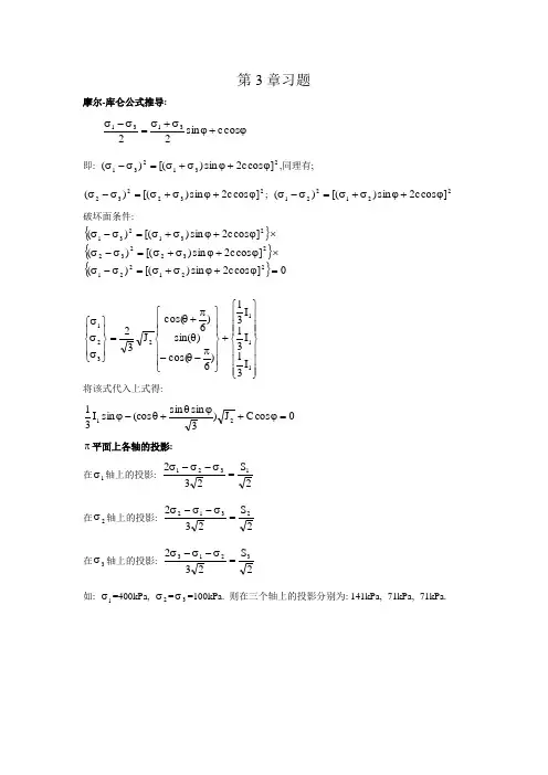
第3章习题摩尔-库仑公式推导:ϕ+ϕσ+σ=σ-σcos c sin 223131 即: 231231]cos c 2sin )[()(ϕ+ϕσ+σ=σ-σ,同理有;232232]cos c 2sin )[()(ϕ+ϕσ+σ=σ-σ; 221221]cos c 2sin )[()(ϕ+ϕσ+σ=σ-σ破坏面条件:{}{}{}0]cos c 2sin )[()(]cos c 2sin )[()(]cos c 2sin )[()(221221232232231231=ϕ+ϕσ+σ=σ-σ⨯ϕ+ϕσ+σ=σ-σ⨯ϕ+ϕσ+σ=σ-σ⎪⎪⎪⎭⎪⎪⎪⎬⎫⎪⎪⎪⎩⎪⎪⎪⎨⎧+⎪⎪⎭⎪⎪⎬⎫⎪⎪⎩⎪⎪⎨⎧π-θ-θπ+θ=⎪⎭⎪⎬⎫⎪⎩⎪⎨⎧σσσ1112321I 31I 31I 31)6cos()sin()6cos(J 32 将该式代入上式得:0cos C J )3sin sin (cos sin I 3121=ϕ+ϕθ+θ-ϕ π平面上各轴的投影:在1σ轴上的投影:2S 2321321=σ-σ-σ在2σ轴上的投影:2S 2322312=σ-σ-σ在3σ轴上的投影:2S 2323213=σ-σ-σ如: 1σ=400kPa, 2σ=3σ=100kPa. 则在三个轴上的投影分别为: 141kPa, -71kPa, -71kPa.1、临界状态:是指土在常应力和常孔隙比下不断变形的状态。
临界孔隙比:表示土在这种密度状态下,受剪作用只产生剪应变而不产生体应变。
水力劈裂:由于孔隙水压力的升高,引起土体产生拉伸裂缝发生和发展的现象。
饱和松砂的流滑:饱和松砂在受静力剪切后,因体积收缩导致超孔压骤然升高,从而失去强度和流动的现象。
真强度理论:为了反映孔隙比对粘土抗剪强度及其指标的影响,将抗剪强度分为受孔隙比影响的粘聚分量与不受孔隙比影响的摩擦分量。
通过不同的固结历史,形成等孔隙比的试样,在不同的法向压力下剪切,试样破坏时的孔隙比相同,强度包线即为孔隙比相同的试样的强度包线,该强度称为在此孔隙比时的真强度。

绝 密★启用前大连理工大学网络教育学院2010年9月份《土力学与地基基础》课程考试 模拟试卷答案考试形式:闭卷 试卷类型:A一、单项选择题(本大题共10小题,每小题2分,共20分)1B 2B 3B 4A 5D 6B 7A 8D 9A 10A二、判断题(本大题共10小题,每题2分,共20分)1A 2A 3B 4A 5B 6A 7A 8A 9B 10A三、简答题(本大题共5小题,每小题6分,共30分)1、内力地质作用:由地球自转产生的旋转能引起的,表现为岩浆活动、地壳运动和变质作用。
外力地质作用:由太阳辐射能和地球重力位能引起,表现为对母岩产生风化、剥蚀、搬运与沉积作用。
2、符合下列条件之一者为一级场地:①对建筑抗震危险的地段;②不良地质现象强烈发育;③地质环境已经或可能受到强烈破坏;④地形地貌复杂;⑤有影响工程的多层地下水、岩溶裂隙水或其他水文地质条件复杂、需专门研究的场地。
3、沉井的作用有:①重型结构物基础。
②江河上的结构物。
③取水结构物。
④地下工程。
⑤邻近建筑物的深基础。
⑥房屋纠倾工作井。
4、库仑土压力理论是根据墙后土体处于极限平衡状态并形成一滑动楔体时,从楔体的静力平衡条件得出的土压力计算理论。
其基本假设是:⑴墙后的填土是理想的散粒体(粘聚力0=c );⑵滑动破坏面为一平面。
5、⑴地基基础设计等级为甲级的建筑物桩基;⑵体型复杂、荷载不均匀或桩端以下存在软弱土层的设计等级为乙级的建筑物桩基; ⑶摩擦型桩基。
四、计算题(本大题共3小题,每小题10分,共30分)1、解: 952.017.11)22.01(72.21)1(=-⨯+⨯=-+=ρρωωs d e%8.48952.01952.01=+=+=e e n %9.62952.072.222.0=⨯==e d s s r ω3/93.13952.011072.21m kN e d s d =+⨯=+=ωγγ3/81.18952.0110)952.072.2(1)(m kN e e d s sat =+⨯+=++=ωγγ3/81.8952.0110)172.2(1)1(m kN e d s =+⨯-=+-='ωγγ2、 解:第一层底:kPa h c 5.255.11711=⨯==γσ第二层土:882.011910)31.01(73.21)1(=-⨯+⨯=-+=γγωωs d e3/2.910882.01173.211m kN e d s =⨯+-=+-='ωγγ地下水位处:kPa h c 0.355.0195.255.2522=⨯+='+=γσ层底: kPa h c 2.675.32.90.350.3522=⨯+="'+=γσ第三层底:123.112.1810)41.01(74.21)1(=-⨯+⨯=-+=γγωωs d e3/2.810123.11174.211m kN e d s=⨯+-=+-='ωγγ kPa h c 8.13282.82.672.6733=⨯+='+=γσ第四层底:771.015.1910)27.01(72.21)1(=-⨯+⨯=-+=γγωωs d e3/7.910771.01172.211m kN e d s =⨯+-=+-='ωγγ kPa h c 9.16137.98.1328.13244=⨯+='+=γσ第五层顶:kPa h c 9.306)385.3(109.1619.161=++⨯+=+=ωωγσ 3、 (1)地基沉降量估算:cm h e e e 3.2180088.0183.088.01S 121=⨯+-=+-=(2)计算附加应力比值α:50.116024021===σσα (3)假设地基平均固结度分别为25%、50%、75%和90%(4)计算时间因子T V :由U 与α查图4-17曲线横坐标可得T V =0.04,0.175,0.45,0.84 (5)计算相应的时间t :①地基土的压缩系数:11125.020.005.020.083.088.0216.024.0-==-=+-=∆∆=MPa e e e σα ②渗透系数单位换算:年/19.01015.3/106.078cm s cm k =⨯⨯⨯=-③计算固结系数:年/14100001.025.01.0)283.088.01(19.01.0)1(C V cm e k m =⨯⨯++=⨯+=ωαγ④时间因子:22V V 80014100C T t H t ==,V v T T t 5.4514100640000==U% 系数α 时间因子T V时间t /年 沉降量s /cm25 1.5 0.04 1.82 5.32 50 1.5 0.175 8 10.64 75 1.5 0.45 20.4 15.96 901.50.8438.219.17t。
大连理工大学Dalian University of Technology Fluid mechanics Chapter 3 Basics of Fluid Flow2.1 Lagrangian and Eulerian descriptions of fluid motionLagrangian descriptionLagrangian description of fluid flow tracks the position and velocity of individual particles.The path of a fluid particle is given by the vector r (t), and can be expressed in terms Cartesian coordinates as()()()()r t x t i y t j z t k=++Velocity field:(,,,)(,,,)(,,,)x a b c t u t y a b c t v t z a b c t w t ∂⎧=⎪∂⎪∂⎪=⎨∂⎪∂⎪=⎪∂⎩acceleration field :222222(,,,)(,,,)(,,,)x a b c t u t y a b c t v t z a b c t w t ⎧∂=⎪∂⎪∂⎪=⎨∂⎪⎪∂=⎪∂⎩大连理工大学Dalian University of TechnologyFluid mechanics Chapter 3 Basics of Fluid Flow2.1 Lagrangian and Eulerian Descriptions offluid motionEulerian descriptionsA flow domain or control volume is defined by which fluid flows in and out.This method to describe fluid motion is to imagine an array of “windows”in the flow field, and have information for the velocity of fluid particles that pass each window for all timeVelocity field:(,,,)(,,,)(,,,)u u x y z t v v x y z t w w x y z t =⎧⎪=⎨⎪=⎩大连理工大学Dalian University of TechnologyFluid mechanics Chapter 3 Basics of Fluid Flow3.3 Streamlines, pathlines and streaklinesStreamlinesA Streamline is a curve that is everywhere tangent to the instantaneous local velocity vector.Consider an arc lengthstreamline must be parallel to the local velocity vectorGeometric arguments results in the equation for a streamlinedr dxi dyj dzk =++V ui vj wk=++dr dx dy dz V u v w ===大连理工大学Dalian University of Technologystreamlines大连理工大学Dalian University of TechnologyFluid mechanics Chapter 3 Basics of Fluid FlowPathlinesA Pathline is the actual path traveled by an individual fluid particle over some time period.Same as the fluid particle's material position vectorParticle location at time t:Particle Image Velocimetry (PIV) is a modern experimental technique to measure velocity field over a plane in the flow field.()()()(),,particleparticle particle xt y t z t starttstart t x x Vdt=+∫大连理工大学Dalian University of TechnologyFluid mechanics Chapter 3 Basics of Fluid FlowExample 3.1A velocity field is given by where V 0and l areconstant, at what location in the flow field is the speed equal to V 0? Make a sketch of the velocity field in the first quadrant(x>0, y>0) by drawing arrows representing the fluid velocity at representative locations()0()V V l xi yj =−Solution:The fluid speed V, is()()1/21/2222220VV u v w x y l=++=+The speed is V=V 0at any location on the circle of radius l centered centered at the origin()1/222x y l+=The direction of the fluid velocity00tan V y l v y u V x l xθ−−===理工大学Dalian University of Technology)Stream function大连理工大学Dalian University of TechnologyFluid mechanics Chapter 3 Basics of Fluid FlowExample 3.3Water flowing from the oscillating slit shown in figure produces a velocity field given bywhere u 0, v 0and ωare constants, Thus, the y component ofvelocity remains constant (v =v 0) and the x components of velocity at y=0 coincides with the velocity of the oscillating sprinkler head [u=u 0sin(wt) at y=0].()000sin V u t y v i v jω=−+⎡⎤⎣⎦(a ) determine the streamline that passes the through the origin at t=0; at t=π/2ω.(b) Determine the pathline of the particle that was at the origin at t=0; at t=π/2ω.(c) Discuss the shape of the streakline that pass through the origin大连理工大学Dalian University of TechnologyFluid mechanics Chapter 3 Basics of Fluid FlowExample 3.3Solution: (streamline)The streamline are given by the solution of()000sin v dy vdx u u t y v ω==−⎡⎤⎣⎦In which the variables can be separated and the equation integrated to give()000sin u t y v dy v dxω−=⎡⎤⎣⎦∫∫()0000cos y u v t v x Cv ωω⎡⎤⎛⎞−=+⎢⎥⎜⎟⎝⎠⎣⎦x=0,y=0,t=0----------Æ00C u v ω=00cos 1u y x v ωω⎡⎤⎛⎞=−⎢⎥⎜⎟⎝⎠⎣⎦x=0,y=0,t=π/2ω----------ÆC=00cos 2u y x v πωω⎛⎞=−⎜⎟⎝⎠大连理工大学Dalian University of TechnologyFluid mechanics Chapter 3 Basics of Fluid FlowExample 3.31020sin C x u t C v ω⎡⎤⎛⎞=−+⎢⎥⎜⎟⎝⎠⎣⎦Solution: (pathline)The pathline of a particle can beobtained from the velocity field and the definition of the velocity ()000sin dx dyu t y v and v dtdtω=−=⎡⎤⎣⎦The y equation can be integrated to givethe y coordinate of the pathline as 01y v t C =+0110000sin sin v t C C dxu t u dt v v ωω⎡⎤⎛⎞⎛⎞+=−=−⎢⎥⎜⎟⎜⎟⎝⎠⎝⎠⎣⎦X=y=0,t=0----ÆC 1=C 2=000x and y v t==X=y=0,t=π/2ω----ÆC 1=-πv 0/2ωC 2=-πu 0/2ω0022x u t and y v t ππωω⎛⎞⎛⎞=−=−⎜⎟⎜⎟⎝⎠⎝⎠0v y xu =大连理工大学Dalian University of TechnologySolution: (streakline)大连理工大学Dalian University of TechnologyFluid mechanics Chapter 3 Basics of Fluid Flow3.4 One-, two, and three-dimensional flowsGenerally, a fluid flow is a rather complex three-dimensional, time-dependent phenomenon.It is possible to make simplify assumptions that allow a much easier understanding of the problem without sacrificing needed accuracy. One of these simplifications involves approximating a real flow as a simpler one-or two-dimensional flow.three-dimensional flow(,,,)V V x y z t ui vj wk==++大连理工大学Dalian University of TechnologyFluid mechanics Chapter 3 Basics of Fluid FlowTwo-dimensional flowIn many situations one of the velocity components may be small (in some sense) relative to the two othercomponents.In situations of this kind it may be reasonable to neglect the smaller component and assume two dimensional flow. (,,)V V x y t ui vj==+Stream filament: the fluid in the stream tube大连理工大学Dalian University of Technologyfinite flow cross大连理工大学Dalian University of TechnologyFluid mechanics Chapter 3 Basics of Fluid Flow3.5 Some fundamental conception for fluid flow Uniform flow: is one in which the velocity is the same on both magnitude and direction at a given instant at every point in the flow.This strict definition of uniform flow can have little meaning for the flow a real fluid where the velocity varies acrosssection. But when the size and shape of cross section areconstant along the length of channel under consideration. We say the flow is uniform.0V n∂=∂acceleration 大连理工大学Dalian University of TechnologyFluid mechanics Chapter 3 Basics of Fluid Flow3.5 Some fundamental conception for fluid flow Non-uniform flow:is one in which the velocity is variable at a given instant at every point in the flow.the flow cross section is curved surface.The size and shape of flow cross section varies along the direction of fluid flow The mean velocity is variable along the direction of fluid flow大连理工大学Dalian University of TechnologyFluid mechanics Chapter 3 Basics of Fluid Flow3.5 Some fundamental conception for fluid flow Gradually varied flow:i s one in which the curvature radius of streamline is large.Since the streamlines is almost parallel, the angle between the streamlines is small. With small remove acceleration and the inertia force can be neglected.大连理工大学Dalian University of TechnologyFluid mechanics Chapter 3 Basics of Fluid Flow3.5 Some fundamental conception for fluid flow Rapidly varied flowThe angle between the streamlines is large.With larger curvature radius With larger remove acceleration and the inertia force can not be neglected.大连理工大学Dalian University of TechnologyFluid mechanics Chapter 3 Basics of Fluid Flow3.6 Flow rate and mean velocityFlow rate: the quantity of fluid flowing per unit time across any section.Volume flow rate (discharge) : SI unit, cubic meters per second (m 3/s)Mass flow rate: SI unit, kilogram per second (kg/s) Weight flow rate: SI unit, kilonewtons per second (kN/s)The volume flow rate passing through the element of area dA is Element Mean velocity ()cos (cos )'dQ u dA u dA u dA udA θθ==== i dA’is projection of dA on the plane normalto the direction of u. 大连理工大学Dalian University of Technology Fluid mechanics Chapter 3 Basics of Fluid Flow3.6 Flow rate and mean velocityMass flow rate and the weight flow rateThe flow rate in a real fluidmQ ρ= G Q γ=A A Q dQ udA AV===∫∫A A m dQ udA AV Q ρρρρ====∫∫ AG gmudA AV Q γγγ====∫ u : is the time mean velocity throughan infinitesimal area dA.V: is mean velocity over the entire sectional area A大连理工大学Dalian University of TechnologyFluid mechanics Chapter 3 Basics of Fluid Flow3.7 Equation of continuityFluid system and control volumeFluid system: a continuous mass of fluid that always contains the same fluid particle.¾The mass of a system is constant¾The shape of the system, and so the boundaries, may change with time.¾The size and shape of system is entirely optional.大连理工大学Dalian University of TechnologyCV character of this term大连理工大学Dalian University of TechnologyFluid mechanics Chapter 3 Basics of Fluid FlowFluid flow from the fire extinguisher tank. Discuss the differences between dB sys /dt and dB cv /dt if B represent mass.Example 3.4Solution:0sys sys sys d dV dB m dt dt dtρ⎛⎞⎜⎟⎜⎟∂⎝⎠===∫0CVCV CV d dV dB m dt dt dtρ⎛⎞⎜⎟∂⎝⎠==<∫大连理工大学Dalian University of TechnologyFluid mechanics Chapter 3 Basics of Fluid Flow3.7 Equation of continuityConsider a steam tube shown in figureNo fluid can leave or enter the stream tube except at the ends.The fixed volume between the two end sections is a control volume, of volume V.out in CV cv c s v ys B B DB B t t t Dt ∂∂∂=+−∂∂∂CV CV CV dm d V V t dt t ρρ∂==∂∂222222out cvdB A V dt A V dt dt ρρ==111111in cv dB AV dt AV dt dt ρρ==111222CV V AV A V tρρρ∂=−∂111222111222AV A V m AV A V gm G ρργγ===== For steady flowThe mass flow rate in isSo the mass is accumulating in the tank atthe rate of 14.5 kg/s大连理工大学Dalian University of Technology Fluid mechanics Chapter 3 Basics of Fluid FlowA 10-cm jet of water issues from a 1-m diameter tank, as shown. Assume that the velocity in the jet is (2gh)1/2m/s. How long it take for the water surface in the tank to drop from h 0=2m to h f =0.5m?Example 3.6Solution:We will let the control surfacesurround the volume of liquidwithin the tank at all times, so thatthe control volume will decrease insize as time passes.大连理工大学Dalian University of TechnologyFluid mechanics Chapter 3 Basics of Fluid Flow3.8 Energy equation for steady flow ofincompressible fluids along a streamlineConsider a stream tube, two cross sectional areas d A 1,d A 2at right angles to the streamline, elevation of d A 1,d A 2are Z 1and Z 2, Velocity of the fluid are u 1, u 2in section 1 and section 2,respectively. And the pressure is p 1 and p 2Assumption:The flow is steady;The fluid is isothermal,incompressibleand inviscid.Apply work energy theoremto the fluid system within thestream tube between the twoends.大连理工大学Dalian University of TechnologyFluid mechanics Chapter 3 Basics of Fluid Flow3.8 Energy equation for steady flow ofincompressible fluids along a streamlineIncrease of mechanical energyThe increase of mechanical energy can be obtained by comparing the spaces that the fluid system occupy before and after dt.Before dt, the space occupied by fluid is 1-1’+1’-2After dt, the space occupied by fluid is 1’-2+2-2’ the volume 1’-2 is the same before and after dt , so thepotential energy and the kinetic energy is invariable.Hence, The increase of the mechanicalenergy of the fluid system is onlyassociated with the increase due tothe new volume occupied 2-2’anddecrease duo to the volume 1-1’left inthe fluid system.大连理工大学Dalian University of Technology Fluid mechanics Chapter 3 Basics of Fluid Flow3.8 Energy equation for steady flow ofincompressible fluids along a streamlineThe volume of 1-1’,2-2’is dQdtMass is Increase of kinetic energy:Increase of potential energy Applying work energy theoremdQdt dQdt gγρ=22222212112222u u u u dQdt mu dQdt g g g γγ⎛⎞⎛⎞−==−⎜⎟⎜⎟⎝⎠⎝⎠()21dQdt Z Z γ−()()2221122122u u p p dQdt dQdt dQdt Z Z g g γγ⎛⎞−=−+−⎜⎟⎝⎠2211221222p u p u Z Z g gγγ++=++Bernoulli equation大连理工大学Dalian University of TechnologyFluid mechanics Chapter 3 Basics of Fluid FlowPitot TubeStatic pressureIn a flowing fluid, we call the fluid pressure p the static pressure because it is the pressure that an instrument would measure if it were static with respect to the fluid, i.e., moving with the fluid. We measure it with piezometer tubes and other devices that attempt to minimize disturbance to the flow. To measure the static pressure in a flow field, we use a static tube. in this device the pressure is transmitted to a gage or manometer through piezometric holes that are evenly space around the circumference of the tube.Holes大连理工大学Dalian University of Technologyobtainable along a given streamline.大连理工大学Dalian University of TechnologyFluid mechanics Chapter 3 Basics of Fluid FlowPitot TubeStatic headTotal head Small holes on bothsides of outer tube Stagnation point Writing Bernoulli equation alongthe streamline ab22a b p p u g γγ=+2a b p p u g γ−=a b v p p h γ−=2vu gh ϕ=Coefficient of instrument: because rarely are the piezometer holes located in precisely the correct position toindicate the true value of p /γ大连理工大学Dalian University of TechnologyFluid mechanics Chapter 3 Basics of Fluid Flow3.9 Pressure in fluid flowFor the uniform flow, the inertial force disappears, now let us consider how pressure varies over a cross section of flow in a uniform conduit. The figure shows a small prism of the flowing fluid.Forces parallel to the direction of motion, namely the pressure and friction forces and the weight component, must balance out if the flow is steady and parallel.N N The projection of friction forces tothe axis N-N is zero, so the forcesalong N-N, namely pressure andweight component, must balance.12cos 0p A Ay p A γα+−=1212p p Z Z γγ+=+大连理工大学Dalian University of TechnologyFluid mechanics Chapter 3 Basics of Fluid Flow3.9 Pressure in fluid flowThe pressure variation over a cross section perpendicular to the streamline show that in any plane perpendicular to the direction of parallel and steady flow the pressure varies according to thehydrostatic law. The average pressure is then the pressure at the centroid of such an area.In other words, on a horizontal axis through the conduit andperpendicular to its centerline the pressure is everywhere the same. Since the velocity is higher near the center than near the walls, it follows that the local energy head is also near the center.The height of liquid column are the sameThe streamline is almost parallel forthe gradually varied flow, so it can bedealt with as uniform flow大连理工大学Dalian University of TechnologyFluid mechanics Chapter 3 Basics of Fluid FlowExample 3.7Fluid (water) )flowing in a inclined pipe, the pressure of point A measured by U-tube manometer using mercury is shown in figure. Determine the pressure of point ASolution:Since the point A and point B locate in the same cross section,the hydrostatic law can be satisfied in the cross section.'0.60.3A p γγ+=20.3980713.60.6980734.23/A p kN m =××−×=Note that although point E , D and A locateon the same horizontal plane, the pressureof point E and D are not equal to point A.1Ap ⎜⎝∫A ∫2A大连理工大学Dalian University of TechnologyFluid mechanics Chapter 3 Basics of Fluid Flow3.10 Energy equation for steady flow of incompressible(b) Kinetic energy2323322222Q A A Au u V dQ dA u dA V dA Q g g g g g γγαγγαγ====∫∫∫∫3333A A A u dA u dA V AV dAα==∫∫∫Kinetic energycorrection factor V: mean velocity in the cross section23311111222A A u dA V V Q g g dA g αγγαγ==∫∫23322222222A A u dA V V Qg g dA g αγγαγ==∫∫大连理工大学Dalian University of Technology Fluid mechanics Chapter 3 Basics of Fluid Flow3.10 Energy equation for steady flow of incompressible(c) Energy loss'1212l l Qh dQ h dQγγ−−=∫Represents the negative work done by viscousfriction per unit time when the fluid across thesection flows from section 1 to section 222111222121222l p V p V Z Z h g g ααγγ−⎛⎞⎛⎞++=+++⎜⎟⎜⎟⎝⎠⎝⎠p 1, Z 1: pressure and elevation for the same point in cross section 1p 2, Z 2: pressure and elevation for the same point in cross section 2Both are absoluteor gage pressure2g大连理工大学Dalian University of TechnologyMass conservation123Q Q Q =+22111222121222l p V p V Z Z h ggααγγ−++=+++22333111131322l p V p V Z Z h ggααγγ−++=+++Generally we can write an energy equation that will fulfill conditions 4and 5. if there are two unknowns in the equation then we must also use the continuity equation.Example 3.8Solution:(1)Choose section 1-1 and 2-2 as flow cross section=2g大连理工大学Dalian University of TechnologyFluid mechanics Chapter 3 Basics of Fluid FlowExample 3.8Z 1=4m, Z 2=0, p 1/γ=0, p 2/γ=021102V gα≈222222V V ggαα=21232l V h g−=2240000322V V g gα++=+++2 4.43/V g m s==()233.140.14.430.0348/4Q VA m s×==×=Similarly: p M =4.904kN/m 2大连理工大学Dalian University of Technology大连理工大学Dalian University of TechnologyFluid mechanics Chapter 3 Basics of Fluid FlowVenturi meter1122(1)Write the Bernoulli equationbetween section (1) and (2), we have2211220022p V p V g gγγ++=++22122122p p V V h g gγγ−=−=∆(2) According to the continuity equation, we have22112V d V d ⎛⎞=⎜⎟⎝⎠422111222d V V h d g g⎛⎞−=∆⎜⎟⎝⎠141221g h V d d ∆=⎛⎞−⎜⎟⎝⎠22111412112441g h Q V d d d d ππ∆==⎛⎞−⎜⎟⎝⎠Which can be measured by experimental method大连理工大学Dalian University of TechnologyFluid mechanics Chapter 3 Basics of Fluid Flow3.12 hydraulic grade line and energy lineDefinitionHydraulic grade line: if we connected a series of piezometers all along the pipe, the liquid would rise in them to various levels along what is called the hydraulic grade line (HGL) (piezometric line). 22p V H Z gγ=++Elevation headvelocity headPiezometric headTotal engy headStatic pressure headThe z portion of the piezometric head represents the elevation of point A. the vertical distance from point A to the corresponding point on the HGL represent p/γin the flow at point A 大连理工大学Dalian University of TechnologyFluid mechanics Chapter 3 Basics of Fluid Flow3.12 hydraulic grade line and energy lineEnergy line: is above the HGL by a distance V 2/2g. That is the linedrawn through the pitot-tube liquid surfaces.For the flow of an ideal fluid, the energy line is horizontal. For a real fluid, the energy line must slope downward in the direction of flow because of head loss due to fluid friction大连理工大学Dalian University of TechnologyFluid mechanics Chapter 3 Basics of Fluid Flow3.12 hydraulic grade line and energy lineHow to draw hydraulic grade lines and energy lines(1) By definition, the EGL is positioned above the HGL by an amount v 2/2g. Thus if the velocity is zero, as in a lake or reservoir , the HGL and EGL will coincide.(2)Head loss for flow in a pipe or channel always means that the EGL will slope downward in the direction of flow, the only exception to this rule occurs when a pump supplies energy to the flow, then an abrupt rise in the EGL (and the HGL) occurs from the upstream side to the downstream side of the pump.Energy addeda大连理工大学Dalian University of Technologygradual expansion such as at the outlet.Energy removed Gradual expansion大连理工大学Dalian University of TechnologyFluid mechanics Chapter 3 Basics of Fluid Flow3.12 hydraulic grade line and energy lineHow to draw hydraulic grade lines and energy lines(4) if the outlet to a reservoir is an abrupt expansion, all the kinetic energy is lost. Thus the EGL drops an amount v 2/2g at the outlet. (5) If a flow passagechanges diameter,such as in a nozzle or by means of a change in pipe size, the velocity therein will also change, hence, the distance between the EGLand HGL will change, and the slope on the EGL will change.大连理工大学Dalian University of TechnologyFluid mechanics Chapter 3 Basics of Fluid Flow3.12 hydraulic grade line and energy lineHow to draw hydraulic grade lines and energy lines(6) For steady flow in a pipe that has uniform physicalcharacteristics (diameter, roughness, shape, and so on) along its length, the head loss per unit length will be constant. thus the slope of the EGL and HGL will be constant along the length of pipe.(7)If the HGL fall below the pipe, then p/γis negative, indicating subatmospheric pressure.And so on, energy line:1-a-b-b0-c Hydraulic grade line: 1-a’-b’-bo’-c’大连理工大学Dalian University of Technology11221222l p Z p Z p γγ−++=+++But for the gases flow, we must consider the difference ofatmospheric pressure when the specific weight of gases is not equal to that of atmosphere, specially, in the case which the elevation difference is very large.大连理工大学Dalian University of Technology'11a p p p =+()'2221a a p p p Z Z γ=−+−Pressure difference221211221212()22a a a l V V p p Z p p Z Z Z p ρργγγ−+++=+−−+++γa : the specific weight of atmosphere2212121212()()22a l V V p Z Z p p ρργγ−++−−=++Static pressure Kinetic pressure Elevation pressure21()()s a p p Z Z γγ=+−−22q V p p ρ=+221()()2z a Vp p Z Z ργγ=++−−Potential pressure Stagnation pressure Total pressure大连理工大学Dalian University of Technology(2)if the density of the gas ρ=0.8kg/m . (ρa =1.3kg/m )大连理工大学Dalian University of TechnologyFluid mechanics Chapter 3 Basics of Fluid FlowExample 3.10solution(1): writing energy equationbetween the section A and C, Because the density of gas ρ=ρa =1.2kg/m 3, thus22C A lA C V p p ρ−=+22129.8 1.29 1.222C C V V ×=×+××2117.6/12 4.43/C V m s=×=2314.430.0348/4Q d m sπ=×××=The pressure of point B: Writing energy equation between the section B and C2222B lB CV V p p ρρ−+=+22219 1.221.2 1.2222B V V V p ××××=×++224.5 1.252.92/2B V p N m =××=大连理工大学Dalian University of TechnologyFluid mechanics Chapter 3 Basics of Fluid FlowExample 3.10(2): if the density of the gas ρ=0.8kg/m 3, writing energyequation between the section A and C,2()()2C A a A C lA C V p Z Z p ργγ−+−−=+22129.8(1.20.8)9.8400.890.822C C V V ×+−××=×+××8.28/B V m s=30.065/Q m s=Τhe pressure of point B22190.8(1.20.8)9.82045/22B B V p N m =×××−−××=z p ρ=−Zero pressure lineD Unsteady flow∑The rate of change oraccumulation of momentum within the fixed control volumeThe rates at which momentum leaves the control volumeThe resultant force acting on a fluid mass is equal to the rate of change of momentum of the fluid mass大连理工大学Dalian University of TechnologyFluid mechanics Chapter 3 Basics of Fluid Flow3.15 The momentum principleIn the case of steady flow, conditions withinthe control volume do not change, soIf we select a control volume so that the control surface is normal to the velocity where it cuts the flow, and lets us specify that the velocity is constant where it cuts across the control surface.()()out in cvcvd d d mV mV F tdt=−∑()11111d d m dt dtmVm V V == ()22222d d m dt dt mVm V V ==Steady flow2211222111F V m V Q V V mQ ρρ=−=−∑大连理工大学Dalian University of TechnologyFluid mechanics Chapter 3 Basics of Fluid Flow3.15 The momentum principleSince the flow is steady, from continuity, we have121122mm m Q Q ρρ==== According to the vector relation21out inV V V V V ∆=−=−()()()21F V V V V mQ Q ρρ=∆=∆=−∑ The direction of must be the same as that of the velocity change Represents the vectorial summation of all forces acting on the fluid mass in the control volume, including:•Gravity, shear forces•Pressure forces including those exerted by fluid surrounding the fluid mass under consideration as well as the pressure forces exerted by the solid boundaries in contact with the fluid massF ∑F ∑ρAV(2(2V Qβyx大连理工大学Dalian University of TechnologyFluid mechanics Chapter 3 Basics of Fluid FlowExample 3.12Energy equation: in free-surface flow such as this where the streamlines are parallel, the water surface is coincident with the hydraulic grade line.221122121222l p V p V Z Z hg g γγ−++=+++22122129.8129.81V V +=+××Continuity equation:122313V V ×=×1 2.56/V m s=2 5.11/V m s=2112215.34/Q AV A V m s===4) Free-body diagram of the fluid within the control volume5) Applying momentum equation()1221x F F F Q V V ρ−−=−4.91x F kN =。
第一章土工试验及测试1.1室内试验1.2模型试验1.3原位测试与现场观测1.4 试验的检验与验证第一章土工试验及测试 1.2模型试验)1g的试验:•小比尺模型试验•足尺试验(n=1))n g的模型试验:•离心机模型试验•渗水力模型试验土工模型试验亿美元振动台离心力模拟重力,使模型内的应力和应变条件同现场一致ng 土工模型试验土工离心机模型试验(Centrifuge ))优点:应力应变相等;变形相似;破坏机理及现象相同)缺点:应力场不均匀;材料模拟:土颗粒、薄板片;比尺的不一致;有时边界条件难以模拟)发展:固结、入桩、冻土、基坑开挖、坝体填筑、地震、降雨、喷锚….平衡重吊篮转臂转轴滑环闭路电视计算机数采系统ng 土工模型试验清华大学50gT土工离心机和振动台ng土工模型试验土工离心机试验中的比尺因素土的限制,地面齐平,饱和土ng 土工模型试验渗水力模型试验第一章土工试验及测试 1.2 模型试验-ng 模型试验突出优点是它的设备是静态的,ng 条件下沉桩等比较方便。
明显的局限性:只能做饱和土体试验;地面是水平的;土的渗透系数过大和过小都影响试验精度和造成操作困难。
原位测试与现场观测)平板载荷试验)静力触探)动力触探)十字板剪切试验)旁压试验)螺旋载荷板(SPC )与钻孔剪切仪(BST ))物探试验)原型观测spb E 1(−=oa 段:平板载荷试验糯扎渡现场碾压平板载荷试验静力触探Static Sounding (Static Cone Penetration Test)将金属探头用静力压入土中,通过测定探头所受阻力,分析确定土的某些定量指标。
如砂土的密实度、粘土的不排水强度等 单桥探头:测定总阻力双桥探头:分别测定锥底和侧壁阻力动力触探Dynamic Penetration Test动力触探是用一定重量的击锤,从规定高度自由落下,击打插入土中的探头,测定使探头贯入土中一定深度所需要的击数。
以此确定被测土的物理力学性质。
第3章习题摩尔-库仑公式推导:ϕ+ϕσ+σ=σ-σcos c sin 223131 即: 231231]cos c 2sin )[()(ϕ+ϕσ+σ=σ-σ,同理有;232232]cos c 2sin )[()(ϕ+ϕσ+σ=σ-σ; 221221]cos c 2sin )[()(ϕ+ϕσ+σ=σ-σ破坏面条件:{}{}{}0]cos c 2sin )[()(]cos c 2sin )[()(]cos c 2sin )[()(221221232232231231=ϕ+ϕσ+σ=σ-σ⨯ϕ+ϕσ+σ=σ-σ⨯ϕ+ϕσ+σ=σ-σ⎪⎪⎪⎭⎪⎪⎪⎬⎫⎪⎪⎪⎩⎪⎪⎪⎨⎧+⎪⎪⎭⎪⎪⎬⎫⎪⎪⎩⎪⎪⎨⎧π-θ-θπ+θ=⎪⎭⎪⎬⎫⎪⎩⎪⎨⎧σσσ1112321I 31I 31I 31)6cos()sin()6cos(J 32 将该式代入上式得:0cos C J )3sin sin (cos sin I 3121=ϕ+ϕθ+θ-ϕ π平面上各轴的投影:在1σ轴上的投影:2S 2321321=σ-σ-σ在2σ轴上的投影:2S 2322312=σ-σ-σ在3σ轴上的投影:2S 2323213=σ-σ-σ如: 1σ=400kPa, 2σ=3σ=100kPa. 则在三个轴上的投影分别为: 141kPa, -71kPa, -71kPa.1、临界状态:是指土在常应力和常孔隙比下不断变形的状态。
临界孔隙比:表示土在这种密度状态下,受剪作用只产生剪应变而不产生体应变。
水力劈裂:由于孔隙水压力的升高,引起土体产生拉伸裂缝发生和发展的现象。
饱和松砂的流滑:饱和松砂在受静力剪切后,因体积收缩导致超孔压骤然升高,从而失去强度和流动的现象。
真强度理论:为了反映孔隙比对粘土抗剪强度及其指标的影响,将抗剪强度分为受孔隙比影响的粘聚分量与不受孔隙比影响的摩擦分量。
通过不同的固结历史,形成等孔隙比的试样,在不同的法向压力下剪切,试样破坏时的孔隙比相同,强度包线即为孔隙比相同的试样的强度包线,该强度称为在此孔隙比时的真强度。
高等土力学高等土力学是在本科土力学教材的基础上的进一步延伸,共分七章,包括:土工试验与测试,土的本构关系,土的强度,土中水与土中渗流及其计算,土的压缩与固结,土工数值计算(包括土体稳定的极限平衡计算,土的渗流与固结的有限元计算)。
二、本 构 关 系“本构关系”是英文Constitutive Relation 的意译。
在力学中,本构关系泛指普遍的应力—应变关系。
因为在变形固体力学中,应力不只与应变有关.而且还与物体的加载历时(应力历史)、加载方式(或应力路径)以及温度和时间有关。
因此材科的本构关系或普遍的应力—应变关系可以表示为; 应力路径等),,,(T t f ij ij εσ=式中t 为加载历时,T 为温度。
例如,弹性力学中的广义定律就是最简单的材料本构关系,它不计时间、温度和应力路径及应力历史的影响。
因此应力和应变之间存在着唯一对应的关系。
当材料应力超出弹性范围而进入塑性阶段时,应力和应变之间就没有唯一的对应关系,而是要受应力历史或应力路径的影响,这时材料的应力—应变关系就称为塑性本构关系。
塑性本构关系要比弹性本构关系复杂得多。
如果再考虑材科应力—应变关系随时间和温度的变化,本构关系持更加复杂。
本书所要讲的岩土本构关系主要是指与时间和温度无关的塑性本构关系。
各种本构关系的特点1.弹性本构关系类型和分类弹性本构关系可分为线弹性本构关系和非线性弹性本构关系如图1所示,线弹性本构关系即一般的弹性力学,其应力—应变关系服从广义Hooke 定律。
非线性本构关系的应力—应变曲线是非线性的,但是加卸载仍然沿着一条曲线。
弹性本构关系的基本特征是:1) 应力和变形的弹性性质或可逆性;2) 应力与应变的单值对应关系或与应力路径相应力历史的无关性。
即无论材料单元在历史上受过怎样的加卸载过程或不同的应力施加路径,只要应力不超过弹性限度,应力与应变都是一一对应的;3) 应力与应变符合叠加原理;4) 正应力与剪应变、剪应力和正应变之间没有耦合关系。
大连理工大学22春“土木工程”《土力学与地基基础》期末考试高频考点版(带答案)一.综合考核(共50题)1.天然土若为饱和土,则天然密度与饱和密度相等。
()A.错误B.正确参考答案:B2.测得某土样的液限为45%,塑限为30%,则其塑性指数为15%。
()A.正确B.错误参考答案:B3.反映土透水性质的指标是()。
A.不均匀系数B.相对密实度C.压缩系数D.渗流系数参考答案:D4.填方工程的施工中,常用土的干密度来评价填土的压实程度。
()A.错误B.正确参考答案:B5.A.30°B.45°C.60°D.90°参考答案:B6.根据与地层对比和古生物学方法,把地质年代划分为5代,其正确的顺序是()。
A.太古代、元古代、古生代、中生代、新生代B.元古代、太古代、古生代、中生代、新生代C.中生代、元古代、太古代、古生代、新生代D.太古代、中生代、元古代、古生代、新生代参考答案:A7.由于建筑物的建造而在基础底面处所产生的压力增量称为()。
A.基底压力B.基底反力C.基底附加压力D.基底净反力参考答案:C8.瑞典条分法在分析时忽略了()。
A.土条间作用力B.土条间法向作用力C.土条间切向作用力D.土条间应力和应变参考答案:A9.下列关于渗流力的描述不正确的是()。
A.其数值与水力梯度成正比,其方向与渗流方向一致D.渗流力的存在对土体稳定总是不利的参考答案:D10.弱透水层中,若地下水位在短时间内下降,则土中的自重应力不会明显增大。
()A.正确B.错误参考答案:A11.流网中,任意两相邻流线间的渗流量相等。
()T.对F.错参考答案:T12.非挤土桩由于桩径较大,故其桩侧摩阻力常常较挤土桩大。
()A.错误B.正确参考答案:A13.毛细饱和区的孔隙水压力为正值。
()A.错误B.正确参考答案:A14.建筑物基础作用于地基表面的压力,称为()。
A.基底压力D.附加应力参考答案:A15.弱透水层中,若地下水位在短时间内下降,则土中的自重应力不会明显增大。
高等土力学——No.9 Advanced Soil Mechanics主讲老师:郭莹土木工程学院岩土工程研究所3. 6土的强度理论3.6.2 土的经典强度理论1. 特雷斯卡(Tresca)准则及其广义准则2. 米泽斯(Von Mises)准则及其广义准则3. 莫尔-库仑(Mohr-Coulomb)强度准则4. 三个强度准则的讨论1. 特雷斯卡(Tresca )准则与广义特雷斯卡(Extended Tresca )准则——单剪应力132kσσ−=02πsin 2=−⎟⎠⎞⎜⎝⎛+k J θ0212πsin 12=−−⎟⎠⎞⎜⎝⎛+I k J αθ()1231Ik ασσ+=−广义形式α、I 1反映平均主应力影响金属材料或或πsin =−⎟⎞⎜⎛+k J θ六棱柱的表面:π平面上的特雷斯卡与米泽斯准则两个破坏面交点,数学处理时有困难锥面——广义六棱柱面——特雷斯卡2. 米泽斯(Von Mises )和广义米泽斯(extended Von Mises )准则——三剪应力()()()22132322216k=−+−+−σσσσσσ22kJ =kJ =2kq 3=oct23kτ=或或12=−−k I J α0333=−−k p q α广义米泽斯——Drucker-Prager 准则α、I 1反映平均主应力影响σ1σ3σ2圆锥面——广义米泽斯准则圆柱面——米泽斯准则圆形应用起来更方便3. 莫尔-库仑强度准则——单剪切角()f f τσ=莫尔(Mohr )单值函数1313sin 2c tan c σσϕσσϕ−=++f tan c τσϕ=+在一定的应力范围,线性关系-库仑公式莫尔-库仑强度准则(二维应力状态)0cos cos sin sin 31sin 321=+⎥⎦⎤⎢⎣⎡+−ϕθϕθϕc J I 0cos cos sin sin 3131sin =+⎥⎦⎤⎢⎣⎡+−ϕθϕθϕc q p 莫尔-库仑强度准则的应力不变量表达式三轴平面莫尔-库仑强度准则的破坏面与破坏轨迹三维空间π平面非规则六面体非规则六边形:拉压不等4. Tresca、Mises和Mohr-Coulomb三个强度准则的讨论1)Tresca和Mises都没有考虑平均主应力对土的抗剪强度的影响,不能反映土的摩擦特性;2)广义形式考虑了p,但没有考虑破坏面上正应力的影响;3)Tresca准则是最大剪应力准则;Mises是最大八面体剪应力准则,两者与土的摩擦强度不同;4)三轴压缩和伸长试验,用Tresca和Mises(拉压相等)预测的强度相同,显然与实际不符;三个准则在常规三轴压缩试验测得抗剪强度相等。
(θ=-30o)三维应力空间及π平面(I或p为常数)1π平面用广义米泽斯及广义特雷斯卡准则预测伸长试验,得出不合实际的结果o 36.9ϕ′≥(θ= -30o )(θ=30o )砂土用广义米泽斯及广义特雷斯卡准则,将有一个主应力为拉应力(<0)——不可能Mohr-Coulomb强度准则反映了剪切面上剪应力与正应力的关系以及土作为散粒体的摩擦特性,是比较合理的,在土力学中得到了广泛的应用;存在问题:1)与中主应力无关;2)包线假定线性,即ϕ与围压无关;应力水平很大时引起较大误差;3)因为破坏面非光滑连接,数值计算不够方便.广义Mises在应力空间的曲面和π平面的轨迹光滑,数值计算方便;为避免圆半径过大与实际不符,有时采用伸长圆或折中圆。
π平面-圆规则六边形不规则六边形以内切圆来替代内切圆广义米泽斯三轴压缩试验三轴伸长试验-不同破坏准则在π平面上的轨迹3. 6土的强度理论3.6.3 近代的强度理论1.莱特-邓肯(Lade-Duncan)破坏准则2.松冈元-中井照夫(Matsuoka-Nakai)破坏准则3.双剪应力强度理论4.隐式的破坏准则.本构关系-包括应力应变与强度关系土的强度,或者破坏是其应力应变过程的最后阶段,即在微小的应力增量下,会产生很大(或者不可控制)的应变增量。
因而破坏是应力应变关系的最后阶段。
——现代强度理论基本思想。
1.莱特-邓肯(Lade-Duncan)破坏准则适用于砂土的弹塑性模型不相关联的流动法则屈服面、塑性势面、破坏面性状一致1.莱特-邓肯(Lade-Duncan )破坏准则()3131f 3,0f I I I k I =−=31f 3Ik I =()332122121f 2111,,sin3032733f I J J I J I k θθ⎛⎞=−−+−=⎜⎟⎝⎠()323f 27,,2sin392710f p q q q p p k θθ⎛⎞=−−+−=⎜⎟⎝⎠k f :与砂土物理性质有关的材料常数弹塑性本构模型或者或者()()()3f 2121b b kb b ααα++−⎡⎤⎣⎦=+−3132σσσσ−−=b σ1/σ3=α1.莱特-邓肯(Lade-Duncan )破坏准则设可得说明:破坏时,k f 为常数时,α与b 有关,与莫尔-库伦准则不同Lade-Duncan 破坏面破坏面破坏面:在主应力空间是锥形的表面ϕ=90o 正三角形ϕ→0o 趋近圆形破坏轨迹——梨形与砂土真三轴试验结果的比较()3111313a ,270mI I f I I n I p ⎛⎞⎛⎞=−−=⎜⎟⎜⎟⎝⎠⎝⎠修正的Lade-Duncan 破坏准则——微弯的破坏轨迹修正的Lade-Duncan 破坏准则砂土和正常固结粘土,相当成功反映围压影响()3131f 3,0f I I I k I =−=2.松冈元‐中井照夫(Matsuoka-Nakai )破坏准则认为三维主应力状态中的三个莫尔圆对强度都有影响,强度理论包含三个剪切角sin i jij i jσσϕσσ−=+ϕmo23,ϕmo12,ϕmo13sin i jij i jσσϕσσ−=+空间滑动面模型当σ2=σ3时,破坏面倾角均为45°+ϕ',ϕmo23=0,ϕmo12=ϕmo13=ϕ′,()()()222132312f 1312239k σσσσσσσσσσσσ−−−++=−12f 3I I k I =tan 2ϕ12+ tan 2ϕ23+ tan 2ϕ13=1/4(k f‐9)松冈元——中井照夫破坏准则或或松冈元——中井照夫破坏轨迹与莱特-邓肯相似不同强度参数π平面上的破坏轨迹3. 双剪应力强度理论12面体应力的概念()()()131312122323121212σσσσσσσσσ=+=+=+主正应力()()()131312122323121212τσστσστσσ=−=−=−主剪应力它们在主应力空间中作用在一个十二面体上()()()131312122323121212σσσσσσσσσ=+=+=+()()()131312122323121212τσστσστσσ=−=−=−12面体上的双剪应力()()⎪⎪⎪⎩⎪⎪⎪⎨⎧≤=−+++=≥=−+++=)(0)(023231212231323132323121212131213时++当时++当βστβστσσβττβστβστσσβττc b b F c b b F 原理:某土单元上的两个占主导地位的主剪应力及相应的主正应力的函数达到某一极限值时,土单元发生破坏;b 、c 和β为三个材料常数。
一般表达式不等边六棱锥体表面主空间中的双剪强度理论极限面当b =β=0时,退化成特雷斯卡强度准则。
()131312cτσσ=−=当b =0时,退化为莫尔-库仑强度准则()()13131122c σσβσσ−++=()()⎪⎪⎪⎩⎪⎪⎪⎨⎧≤=−+++=≥=−+++=)(0)(023231212231323132323121212131213时++当时++当βστβστσσβττβστβστσσβττc b b F c b b F4. 隐式的破坏准则破坏是土的本构关系的最后阶段;破坏:加微小应力增量d σij ,会产生不可控制的或很大的应变增量;实际上,每个本构模型中都存在一个破坏准则,有的采用上面某一种,有的则隐含在模型之中。
εσd σd σE t →0d ε1→∞如邓肯-张模型——隐式的破坏准则()213t i f 13f 1E E R σσσσ⎡⎤−=−⎢⎥−⎢⎥⎣⎦Mp q =′′=η剑桥模型⎟⎟⎠⎞⎜⎜⎝⎛++−⋅+−=''2222d d 221d p p M M e ηηηηηκλε应力达到强度时,E t →0或者d ε1=d(σ1-σ3)/d E t →∞椭圆屈服面法向与横坐标垂直,η=M ,分母为零,d ε→∞,破坏再如弹塑性模型——广义剪应变:ep d d d εεε+=在弹塑性模型中:ijijgσλε∂∂=d d p HHf A f A ij ij d 1d d d 1d ∂∂−==σσλ∞→λd 当A →0破坏pij ijg f H A H σε∂∂∂=−∂∂∂p ijHε∂∂()p ijH H ε=破坏条件隐含在中破坏准则——包含在这里(应变硬化)常为中的某些参数与土的破坏有关。
即第二章得到——塑性硬化模量3. 6土的强度理论3.6.4关于强度理论的讨论(1)米泽斯和特雷斯卡:只有在饱和软粘土的不排水情况下,才可以使用;(2)莫尔-库仑准则表达了破坏面上正应力与抗剪强度之间的关系;缺点:未考虑中主应力,强度包线是直线;(3)土的强度是土的应力应变的一个特殊阶段;因而土的强度理论可被纳入土的本构模型之中——近代的强度理论的基本思想。
3.7 粘性土的抗拉强度3.7.1 实际工程中的拉伸破坏与开裂1. 不均匀沉降引起的拉伸破坏2. 滑动中的拉伸裂缝不均匀沉降内部裂缝几种由不均匀沉降引起的土体拉伸破坏上埋式管线填土不均匀心墙裂缝堆石沉降小且快,粘土变形被阻止挡土墙后粘性土体粘土滑坡体滑动产生的局部拉应力3.7 粘性土的抗拉强度3.7.2 土的抗拉强度的测定1.单轴拉伸试验2.三轴拉伸试验3.土梁弯曲试验4.径向压裂法5.断裂韧度测定试验.1.单轴拉伸试验3.土梁弯曲试验t 2πQ ldσ=−4.径向压裂法四种径向压裂试验圆柱体立方体梁立方体对角线加压抗拉强度3.7.3 粘性土的联合强度理论1313sin 2c tan c σσϕσσϕ−=++拉伸破坏:剪切破坏:3t σσ′=−在有拉应力作用下,粘性土的破坏可能是剪切破坏,也可能是拉伸破坏,破坏状态的判断有时是困难的3.7 粘性土的抗拉强度①拉伸破坏②未破坏③剪切破坏拉伸破坏与剪切破坏黄直线为莫尔-库仑包线;4sin sin 2t t b b 2σϕστσϕττ++=()()222联合强度理论:既能判断拉伸破坏又能判断剪切破坏莫尔库仑直线+抛物线将包线在拉伸区变弯曲光滑,为抛物线(绿),抛物线部分方程:砂土的振动液化——补充。