丰田控制及计划 英文版_Issue 5 Rev J
- 格式:xlsx
- 大小:85.52 KB
- 文档页数:1


汽车步入上门服务时代2011-08-25 07:01阅读71评论2汽车售后服务或将由此标志着进入上门维修时代。
8月15日,上海汽车正式启动“尊荣体验”售后服务品牌旗下的全新服务产品“宅捷修”,以“到家式”的服务方式和多达50项的服务内容为特色,树立国内汽车售后服务行业的全新标准,这项原本雷克萨斯、奥迪、宝马等国际品牌才有的高端服务,如今上海汽车的所有车主也可以免费体验到。
当前的汽车售后服务已经进入了多元化竞争的时代,或许在不远的将来,汽车上门维修也会像家电上门维修一样,成为行业的新标准。
蒋峻介绍,目前上海汽车以8008200068作为“宅捷修”的预约电话号码,服务网点覆盖所有的4S店,全国范围内已配备超过600辆售后服务车和500支专业外出救援队,共同参与到“宅捷修”服务。
在未来,还会随着客户数量不断增加而继续加大投入。
据悉,“宅捷修”服务对于车丰田汽车英文缩写解释:缩写简称功能说明EBCV Electronic Air Bleed Control Valve 电子空气泄放控制阀ECT Electronically Controlled Transmission/Transaxle ECU电子控制变速箱/变速箱电脑EGR EGR Vacuum Switching Valve EGR真空开关阀ELS Headlight & Defogger Relay 头灯与除霜器继电器ERLY Clod Mixture Heater Relay 冷车混合气加热器继电器EVP Evaporative Purge Vacuum Switching Valve 碳罐真空开关阀E1,E01,E02 Computer Ground 电脑搭铁线E11,E2,K21,K22 Sensor Ground 传感器搭铁FC Circuit Opening Relay 电路开路继电器FCS Fuel-Cut Solenoid 断油电磁阀FP Fuel Pump Relay 燃油泵继电器FF2 Circuit Opening Relay 电流开路继电器G,G1,G2 Distributor 分电盘G-,G+ Distributor(Crank Angle) 分电盘(曲轴角度)HT Oxygen Sensor Heater 含氧传感器加热器HT1 Oxygen Sensor Heater(Main)含氧传感器加热器(主要)HT2 Oxygen Sensor Heater(Sub)含氧传感器加热器(辅助)IDL Throttle Position Sensor 节气门位置传感器IGDA,IGDB Ignitor 点火装置IGF Ignitor 点火装置IG SW Ignitor Switch 点火开关IGT Ignitor (Primary Trigger) 点火装置(初级侧触发)ISC1,ISC2,ISC3,ISC4 Idle Speed Control Valve or Motor 怠速控制阀/马达KNK Knock Sensor 爆震传感器KNK1,KNK2 Knock Sensor 爆震传感器KS Airflow Meter 空气流量计L Shift Position Switch 换档位置开关LP Headlight Relay 头灯继电器L1,L2,L3 Electronically Controlled Transmission/Transaxle,ECU 电子控制变速箱/变速箱电脑PR Fuel Pressure -UP Vacuum Switching Valve 燃油提压真空开关阀A/C A/C Compressor Clutch 空调压缩机离合器ACT A/C Amplifier 空调放大器ACV A/C Idle-Up Vacuum Switching Valve A/C 怠速提升真空开关阀A/D Cruise Control Computer 定速控制电脑AI Air Injection Vacuum Switching Valve 空气喷射真空开关阀AS Air Suction Vacuum Switching Valve 进气真空开关阀BATT Battery 电瓶BRK Cold Enrichment Breaker 冷车加浓控制器BK Brake Switch 刹车开关+B,+B1 EFI Main Relay EFI(电脑)主继电器DFG Defogger Relay 除雾器继电器DG Check Connector 检查接头EACV Electronic Air Control Valve 电子空气控制阀AUTO SHUTDOWN RELAY 自动熄火继电器RAD LO(HI) FAN 散热器低速(高速)风扇ACCLUTCH 空调离合器TRANS SYSTEM 转换系统HEATED REAR 后窗加热GROUND 搭铁AIR COND 空调BACK UP 倒车VEH LAMP 车灯IGN RUN ONLY 仅点火起动DRAW 拖车Starter 马达REAR DEFOG 后窗除霜器Cond Fan Motor 空调风扇电机A.B.S PMP RELAY 防抱死刹车油泵继电器IGNSW 点火开关FOG 雾灯DEFOG 除霜DRL 门锁OIL TEMP SW 机油温度开关KEY BUZZER 钥匙蜂鸣器FUEL PUMP 燃油泵TEMP 水温表TCS 变速器挡位控制KEY BUZ 钥匙蜂鸣器ATC 温度自动控制BLANK 空SWITCH 开关RADIO GRD 收音机搭铁M/T 手动变速器SEAT BELT BUZ 安全带蜂鸣器EGR 废气再循环SPARE LEAD(WIRE) 备用接头(线)FOG LT SW 雾灯开关SHIELDED 屏蔽线IGN SW LT 点火开关指示灯INST PNL CONT LT 仪表板控制灯BDY CON 车身连接器ATF 自动变速箱油ASSR 总成CAT 触媒转换器DI 分电盘点火ECT 发动机冷却温度EFI 电子燃油喷射F 前部FWD 前轮驱动GND 接地点1. Anthrazit 黑1. Pacific 蓝色2. Antiiope 土色3. Pergament 米色4. Blau 蓝色5. Perlbeige 米色6. Brasil 咖啡色7. Piniengrün 绿色8. Cardinalrot 暗红色9. Rot 红10. Dunkel 深11. Saddletan 深棕色12. Dunkelblau 深蓝色13. Sandbeige 米色14. Dunkelbraun 深咖啡色15. Schwarz 黑16. Gelb 黄色17. Siamgrau 灰色18. Grau 灰色19. Silber 银灰20. Grün 绿色21. Silbergrau 银灰出师表两汉:诸葛亮先帝创业未半而中道崩殂,今天下三分,益州疲弊,此诚危急存亡之秋也。
2004款丰田卡罗拉自动变速器系统维修手册(英文版) 40–1AUTOMATIC TRANSMISSION TRANS –AUTOMATIC TRANSAXLE ASSY ATMAUTOMATIC TRANSAXLE ASSY ATM400LF–01PRECAUTION1 The automatic transaxle is composed of highly precision–finished parts necessitating carefulinspection before reassembly because even a small nick could cause fluid leakage or affectthe performance The instructions here are organized so that youwork on only one componentgroup at a time This will help avoid confusion from similar–looking parts of different sub–as-semblies being on your workbench at the same time The component groups are inspected andrepaired from the converter housing side As much as possible complete the inspection repairand reassembly before proceeding to the next component group If a defect is found in a certaincomponent group during reassembly inspect and repair this group immediately If a compo-nent group cannot be assembled because parts are being ordered be sure to keep all parts ofthe group in a separate container while proceeding with disassembly inspection repair andreassembly of other component groupsRecommended ATF T–IV2 All disassembled parts should be washed clean and any fluid passages and holes should beblown through with compressed air3 Dry all parts with compressed air–never use shop rags4 When using compressed air always aim away from yourself to prevent accidentally sprayingATF or kerosene on your face5 The recommended automatic transaxle fluid or kerosene should be used for cleaning6 After cleaning the parts should be arranged in the correct order for efficient inspection repairsand reassembly7 When disassembling a valve body be sure to match each valve together with the correspond-ing spring8 New discs for the brakes and clutches that are to be used for replacement must be soaked inATF for at least 15 minutes before reassembly9 All oil seal rings clutch discs clutch plates rotating parts and sliding surfaces should becoated with ATF prior to reassembly10 All gaskets and rubber O–rings should be replaced11 Do not apply adhesive cements to gaskets and similar parts12 Make sure that the ends of a snap ring are not aligned with one of the cutouts and are installedin the groove correctly13 If a worn bushing is to be replaced the sub–assembly containing the bushing must also be re-placed14 Check thrust bearings and races for wear or damage Replace if necessary15 Use petroleum jelly to keep parts in place16 When working with FIPG material you must observe the followingUsing a razor blade and a gasket scraper remove all the old packing FIPG material from thegasket surfaceThoroughly clean all components to remove all the loose materialClean both sealing surfaces with a non–residue solventParts must be reassembled within 10 minutes of application Otherwise the packing FIPG ma-terial must be removed and reapplied2004 COROLLA RM1037U135140–2AUTOMATIC TRANSMISSION TRANS –AUTOMATIC TRANSAXLE FLUID ATMAUTOMATIC TRANSAXLE FLUID ATM400LG–01ON–VEHICLE INSPECTION1 CHECK THE FLUID LEVELHINTDrive the vehicle so that the engine and transaxle are at normaloperating temperatureFluid temperature 70 – 80 C 158 – 176 FOK if hot a Park the vehicle on a level surface and set the parkingAdd if hot b With the engine idling and the brake pedal depressedshift the shift lever into all ranges from P to L position andreturn to P positionc Pull out the dipstick and wipe it cleand Push it back fully into the pipee Pull it out and check that the fluid level is in the HOT posi-D25120 tionleaks it is necessary to repair or replace O–ringsFIPGs oil seals plugs or other parts2004 COROLLA RM1037U135240–3AUTOMATIC TRANSMISSION TRANS –PARKNEUTRAL POSITION SWITCH ASSY ATMPARKNEUTRAL POSITION SWITCH ASSY ATM400LH–01REPLACEMENT1 REMOVE BATTERY2 REMOVE BATTERY CARRIERa Remove the 4 bolts and battery carrierC801593 DISCONNECT FLOOR SHIFT CABLE TRANSMISSIONCONTROL SHIFTa Remove the nut from the control shaft leverbDisconnect the control cable from the control shaft leverc Remove the clip and disconnect the control cable fromthe control cable bracketC961474 REMOVE PARKNEUTRAL POSITION SWITCH ASSYa Disconnect the parkneutral position switch connectorb Remove the nut washer and control shaft leverc Pry out the lock plate and remove the manual valve shaftnutd Remove the 2 bolts and pull out the parkneutral positionswitchD251245 INSTALL PARKNEUTRAL POSITION SWITCH ASSYa Install the parkneutral position switch to the manual valveshaftb Temporarily install the 2 boltsc Place a new lock plate and tighten the nutTorque55 Nm 56 kgfcm 49 inlbfdTemporarily install the control shaft leverD099572004 COROLLA RM1037U135340–4AUTOMATIC TRANSMISSION TRANS – PARKNEUTRAL POSITION SWITCH ASSY ATMeTurn the lever counterclockwise until it stops then turn itclockwise 2 notchesf Remove the control shaft leverD25126g Align the groove with neutral basic lineNeutralh Hold the switch in position and tighten the 2 boltsBasic LineTorque 55 Nm 56 kgfcm 49 inlbfGrooveD08584i Using a screwdriver stake the nut with the lock plateD08585j Install the control shaft lever washer and nutTorque 125 Nm 127 kgfcm 9 ftlbfk Connect the parkneutral position switch connectorD251256 INSTALL FLOOR SHIFT CABLE TRANSMISSIONCONTROL SHIFTa Temporarily install the control cable to the control shaft le-ver with nutb Install the control cable and clip to the bracketC961472004 COROLLA RM1037U135440–5AUTOMATIC TRANSMISSION TRANS –PARKNEUTRAL POSITION SWITCH ASSY ATM7 INSTALL BATTERY CARRIERa Install the battery carrier and 4 boltsTorque 13 Nm 132 kgfcm 10 ftlbfC801598 ADJUST SHIFT LEVER POSITION See page 40–449 INSPECT SHIFT LEVER POSITION See page 40–4410 INSPECT PARKNEUTRAL POSITION SWITCH ASSY See page 40–62004 COROLLA RM1037U135540–6AUTOMATIC TRANSMISSION TRANS –PARKNEUTRAL POSITION SWITCH ASSY ATM400LI–01ADJUSTMENT1 INSPECT PARKNEUTRAL POSITION SWITCH ASSYa Apply the parking brake and turn the ignition switch ONb Depress the brake pedal and check that the engine starts only when the shift lever is set in N or P posi-tion and it does not start in the other positionc Check that the back–up light comes on and the reverse warning buzzer sounds only when the shiftlever is set in R position and these do not function in the other positionsIf a failure is found check the park neutral position switch for continuity2 ADJUST PARKNEUTRAL POSITION SWITCH ASSYa Loosen the 2 bolts of park neutral position switch and setNeutralBasic Line the shift lever to the N positionb Align the groove and neutral basic linec Hold the switch in position and tighten the 2 boltsTorque 55 Nm 56 kgfcm 49 inlbfd After adjustment perform the inspection described inGroovestep1D255142004 COROLLA RM1037U135640–7AUTOMATIC TRANSMISSION TRANS – AUTOMATIC TRANSAXLE ASSY ATMAUTOMATIC TRANSAXLE ASSY ATM400LJ–01COMPONENTSHood Sub–assyAir Cleaner Assy13 132 1070 71 62 inlbf70 71 62 inlbfBatteryCylinder HeadCover No2 12 122 91275 130 913 132 1010 102 7Control Cable Support255 260 19StarterAssy39 400 2913 132 10 wo ABSOil Cooler Inlet Tube No1Oil Cooler OutletTube No1 39 400 29 13 132 10Floor ShiftCable Transmission345 350 25Control Shift55 56 49 inlbfClipSpeedometer sensorTransmission Oil Filler connectorTube Sub–assy55 56 49 inlbf Battery Carrier12 1229 Automatic Transaxle AssyO–ringATF Level Gauge12 122 9 Transmission Control CableNm kgfcm ftlbf Specified torque Bracket No1Non–reusable part C953482004 COROLLA RM1037U135740–8AUTOMATIC TRANSMISSION TRANS– AUTOMATIC TRANSAXLE ASSY ATM80 815 59Front Drive Shaft Assy RH52 530 3852 530 38Snap Ring Engine MountingBracket LHTorque Converter Clutch Assy64 65047 Engine Mounting52 530 38Insulator LHx 646 470 3428 285 20Snap Ring23 235 17 Front Drive Shaft Assy LHFlywheel Housing Under CoverTransmission Case Protector18 182 14Automatic Transaxle AssyEngine Mounting Insulator RREngine Mounting 87 887 64Bracket RR 64 652 47Engine Mounting Bracket FR64 652 47Engine Under Cover RH52530 3852 530 38Engine Under Cover LH 64 652 4764 652 4752 530 38FrontSuspension Member DynamicDamper52 530 38Engine Mounting MemberSub–assy CenterNm kgfcm ftlbf Specified torque 39 398 29Non–reusable part C953492004 COROLLA RM1037U135840–9AUTOMATIC TRANSMISSION TRANS –AUTOMATIC TRANSAXLE ASSY ATM400LK–02REPLACEMENT1 REMOVE HOOD SUB–ASSY2 REMOVE CYLINDER HEAD COVER NO23 REMOVE BATTERY4 REMOVE BATTERY CARRIERa Remove the4 bolts and battery carrierC801595 REMOVE AIR CLEANER ASSEMBLY WITH HOSE6 REMOVE FLOOR SHIFT CABLE TRANSMISSIONCONTROL SHIFTa Remove the nut from the control shaft leverb Disconnect the control cable from the control shaft leverc Remove the clip and disconnect the control cable fromthecontrol cable bracketC961477 REMOVE TRANSMISSION CONTROL CABLESUPPORTa Disconnectthe wire harness clamp and control cablefrom thecontrol cable supportb Remove thebolt and control cable supportC957508 REMOVE TRANSMISSION CONTROL CABLE BRACKET NO1a Remove the 2 bolts and control cable bracket2004 COROLLA RM1037U135940–10AUTOMATIC TRANSMISSION TRANS –AUTOMATIC TRANSAXLE ASSY ATM9 DISCONNECT WIRE HARNESSa Remove the2 bolts and disconnect the 2 wire harnessesb Remove the bolt and disconnect the wire harness clampbracketC93666c Remove thebolt and disconnect the wire harness clampbracketC9364310 DISCONNECT CONNECTORa Disconnect the transmission wire connectorb Disconnect the parkneutral position switch connectorc wo ABSDisconnect the speedometer sensor connector11 REMOVE TRANSMISSION OIL FILLER TUBESUB–ASSYa Remove the ATF lever gaugeb Remove the 2 bolts oil cooler tube clamp and oil fillertubec Remove theO–ring from the oil filler tubeD0996112 DISCONNECT OIL COOLER INLET TUBE NO1a Using SST disconnect the oil cooler inlet tube No 1SST 09023–12700SSTC9364613 DISCONNECT OIL COOLER OUTLET TUBE NO1a Using SST disconnect the oil cooler outlet tube No 1SST 09023–127002004 COROLLA RM1037U136040–11AUTOMATIC TRANSMISSION TRANS –AUTOMATIC TRANSAXLE ASSY ATM14 DISCONNECT OXYGEN SENSOR CONNECTORa Remove the foot restb Pull up the floor carpetc Disconnect the oxygen sensor connectorNo 1 No 2 15 SUSPEND ENGINE ASSYEngine Hanger Engine Hanger a Disconnect the 2 PCV hosesb Install the No1 and No2 engine hangers in the correctdirectionParts NoNo1 engine hanger 12281–22021No2 engine hanger 12281–15040Bolt91512–B1016Front Rear D25372 Torque 38 Nm 387 kgfcm 28 ftlbfc Attach the engine chain hoist to the engine hangersCAUTIONDo not attempt to hang the engine by hooking the chain toany other parts16 REMOVE FRONT WHEELS17 REMOVE ENGINE UNDER COVER RH18 REMOVE ENGINE UNDER COVER LH19 DRAIN AUTOMATIC TRANSAXLE FLUIDa Remove the drain plug and gasket and drain ATFb Install a new gasket and drain plugTorque 175 Nm 178 kgfcm 13 ftlbf20 REMOVE EXHAUST PIPE ASSY FRONT See page 15–221 REMOVE FRONT DRIVE SHAFT ASSY RH See page 30–6SST 09520–01010 09520–24010 09520–32040 22 REMOVE FRONT DRIVE SHAFT ASSY LH See page 30–6SST 09520–01010 09520–24010 09520–3204023 REMOVE AUTOMATIC TRANSMISSION CASE PROTECTORa Remove the 2 bolts and case protector24 REMOVE STARTER ASSYa Remove the nut and disconnect the starter wireb Disconnect the connectorc Remove the 2 bolts and starter25 SUPPORT AUTOMATIC TRANSAXLE ASSYa Support the automatic transaxle with a transmission jack26 REMOVE TRANSVERSE ENGINE ENGINEMOUNTINGINSULATORa Remove the 5bolts nut and engine mounting insulatorLHD099642004 COROLLA RM1037U136140–12AUTOMATIC TRANSMISSION TRANS –AUTOMATIC TRANSAXLE ASSY ATM27 REMOVE TRANSVERSE ENGINE ENGINEMOUNTINGBRACKETa Remove the3 bolts and engine mounting bracket LHD0996528 REMOVE TRANSVERSE ENGINE ENGINEMOUNTING INSULATORa Remove thebolt from the engine mounting bracket RRC80192b Remove the3 nuts bolt and engine mounting insulatorRR from the suspension memberC8016729 REMOVE TRANSVERSE ENGINE ENGINEMOUNTING INSULATORa Remove thebolt and nut from the engine mounting brack-et FRC8016630 REMOVEENGINE MOUNTING MEMBER SUB–ASSYCENTERa Remove the4 bolts dynamic damper and member sub–assycenter with engine mounting insulator FRC953542004 COROLLA RM1037U136240–13AUTOMATIC TRANSMISSION TRANS –AUTOMATIC TRANSAXLE ASSY ATM31 REMOVETRANSVERSE ENGINE ENGINEMOUNTINGBRACKETa Remove the 2bolts and engine mounting bracket FRC8017232 REMOVE TRANSVERSE ENGINE ENGINEMOUNTINGBRACKETa Remove the 3bolts and engine mounting bracket RRC9364533 REMOVE FLYWHEEL HOUSING UNDER COVER34 REMOVE AUTOMATIC TRANSAXLE ASSYa Turn the crankshaft to gain access and remove the 6 boltswhile holding the crankshaft pulley bolt with a wrenchF00478b Remove the 6 boltsc Separate and remove the automatic transaxleD0996635 REMOVE TORQUE CONVERTER CLUTCH ASSY36 INSPECT TORQUE CONVERTER CLUTCH ASSY See page 40–20SST 09350–32014 09351–32010 09351–320202004 COROLLA RM1037U136340–14AUTOMATIC TRANSMISSION TRANS –AUTOMATIC TRANSAXLE ASSY ATM37 INSTALL TORQUE CONVERTER CLUTCH ASSYa Install the torque converter clutch to the automatic trans-axleb Using vernier calipers measure the dimension A be-tweenthe transaxle fitting part and the converter fittingpart of the drive plateC63993c Using vernier calipers and a straight edge measure thedimension B shown in the illustration and check that Bisgreater than A measured in bStandardA 1 mm or moreNOTICEDo not add the thickness of straight edgeC6591138 INSTALL AUTOMATIC TRANSAXLE ASSYa Install the automatic transaxle and 6 bolts to the engineTorqueABolt A 64 Nm 650 kgfcm 47 ftlbfB Bolt B。

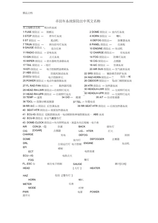
丰田车系统保险丝中英文名称英文缩略语名称 相关的系统1 FUSE 保险丝 --- 熔断丝2 DOME 保险丝 --- 室内灯系统3 STOP 保险丝 --- 停车灯系统4 HORN 保险丝 ---喇叭 5 ST 保险丝 ---起动机6 DEFOG 保险丝--- 除雾器系统7 TRUN 保险丝 --- 转向信号灯系统8 PANEL 保险丝 ---仪表板 9 GAUGE 保险丝 --- 组合仪表10 ENGINE 保险丝 --- 发动机 11 RADIO 保险丝 -- 音响系统12 CHARGE 保险丝 ---充电系统13 IGN 保险丝 ---点火系统14 FOG 保险丝---防雾灯系统 15 WIPER 保险丝 -- 刮水器和洗涤器系统16 CIG 保险丝---点烟器 17 TAIL 保险丝 -- - 尾灯18 A/C 保险丝 ---空调系统19 EFI 保险丝 --- 电子控制燃油喷射系20 AIR SUS 保险丝 --- 空气悬架系统21 ABS 保险丝 ---------------- 防抱死制动系统22 SRS 保险丝 -- 辅助乘员保护系统23 ECU 保险丝 ---------------- 电子控制单元24 HAZ-HORN 保险丝--- -- 危险 - 喇叭 25 POWER 保险丝--- 电动车窗控制系统26 CBDOOR 保险丝--- 电动门锁控制系统27 FL RAD FAN 保险丝 --- 散热器风扇28 HTR 保险丝 --- 加热器系统29 HEAD RH-LWR 保险丝---右前照灯近光30 HEADLH-LWR 保险丝 --- 左前照灯近光 31 HEAD RH-UPR 保险丝 --- 右前照灯远光32 HEADLH-UPR 保险丝 --- 左前照灯远光 33 TEMP --- 温度 34 O/D --- 超速 35 A/T --- 自动变速器36 TDCL --- 故障诊断连接器 37 TEL - -- 车载电话38 RR A/C --- 保险丝 后空调系统 39 RR SEAT-HTR 保险丝 --- 后座加热器系统40 SEAT-HTR 保险丝--- 前座加热器系统41 ECU-IG 保险丝 巡航控制系统、电动倾斜和伸缩控制系统、 ABS 系统 42 ECU-B 保险丝 安全气囊警告灯43 DOME-CLOCK 保险丝---车内照明系统、液晶车内后视镜、电子表危险 ,[ 警告灯 ]HORN 源开关精品文档CON [A , [CIGAR] CHARGE AIRCIGDOME DRL EFIECT ECU---IGFOG FL..ESC 台 HEADC]空调 BACK 点烟器充电LIG 。

控制计划第一版英文版Here's a draft of a control plan in English, following the given requirements:Alright, let's get started with the first draft of our control plan. First things first, we need to identify the key areas we want to focus on. That means breaking down the entire process into manageable chunks.For starters, we gotta set clear goals. Not just vague ones, but specific, measurable targets that we can track progress against. Remember, goals without metrics are just wishes.Communication is crucial, too. We need to ensure everyone is on the same page and knows their roles and responsibilities. Regular check-ins and team meetings will help keep everyone updated.Risk management is another biggie. We can't predicteverything, but we can certainly identify potential issues and have contingency plans ready. It's all about being proactive, not reactive.Now, let's talk about resources. We need to allocate the right people, tools, and time to make this plan successful. Don't forget to consider external factors like budget and availability.Monitoring and evaluation are also essential. We need to keep an eye on things and adjust as we go. Remember,this is a fluid plan – it's not set in stone. Flexibility is key.Lastly, let's not forget about the end goal. What are we ultimately aiming for? Clarity on that will help us stay focused and make sure we're moving in the right direction.So there you have it – a high-level overview of our control plan. Remember, this is just the first draft, so feel free to suggest changes or add your own ideas. We're all in this together!。
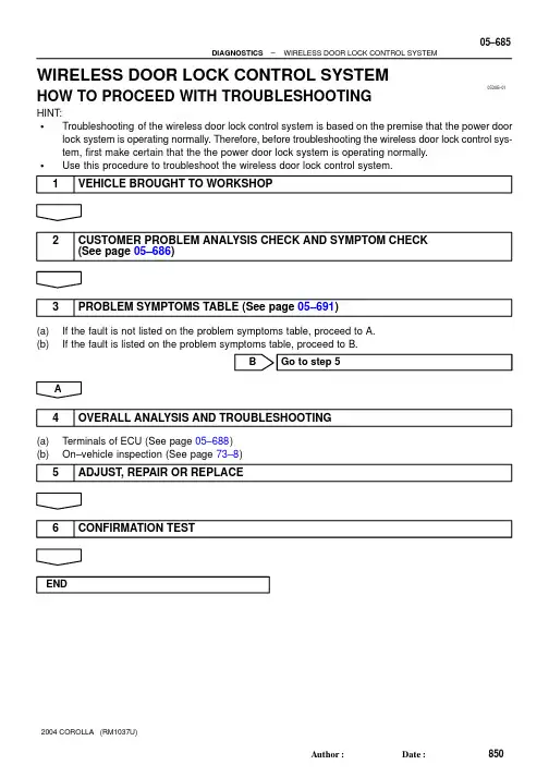
05DUB–01–DIAGNOSTICSWIRELESS DOOR LOCK CONTROL SYSTEM05–685850AuthorĂ:DateĂ:2004 COROLLA (RM1037U)WIRELESS DOOR LOCK CONTROL SYSTEMHOW TO PROCEED WITH TROUBLESHOOTINGHINT:STroubleshooting of the wireless door lock control system is based on the premise that the power door lock system is operating normally. Therefore, before troubleshooting the wireless door lock control sys-tem, first make certain that the the power door lock system is operating normally.SUse this procedure to troubleshoot the wireless door lock control system.1VEHICLE BROUGHT TO WORKSHOP2CUSTOMER PROBLEM ANALYSIS CHECK AND SYMPTOM CHECK (See page 05–686)3PROBLEM SYMPTOMS TABLE (See page 05–691)(a)If the fault is not listed on the problem symptoms table, proceed to A.(b)If the fault is listed on the problem symptoms table, proceed to B.BGo to step 5A4OVERALL ANALYSIS AND TROUBLESHOOTING(a)Terminals of ECU (See page 05–688)(b)On–vehicle inspection (See page 73–8)5ADJUST , REPAIR OR REPLACE6CONFIRMATION TESTEND056B8–07WIRELESS DOOR LOCK CONTROL SYSTEM Check SheetCustomer’s NameVINProduction Date Licence No.Odometer ReadingInspector’s Namekm miles//////Date Vehicle Brought inDate Problem First Occurred Frequency Problem OccursWeather Conditions When Problem OccurredDate Transmitter Battery Last ReplacedWeatherOutdoorTemperature PlaceConstant Sometimes ( times/per day, month)Once onlyFine Cloudy Rainy SnowyVarious/OthersHotWarm CoolCold (Approx. °C ( °F))EverywhereSpecific Locality ( )//P r o b l e m S y m p t o m sWhole wireless door lock control system does not operate.Only door unlock function does not operate.Only door lock function does not operate.Doors are locked by wireless door lock operation even when doors are open.Wireless door lock functions abnormally.Others05–686–DIAGNOSTICSWIRELESS DOOR LOCK CONTROL SYSTEM851AuthorĂ:DateĂ:2004 COROLLA (RM1037U)CUSTOMER PROBLEM ANALYSIS CHECK056BB–04B59374Front Door Lock LHRear Door Lock LHFront Door Courtesy Switch LHRear Door Lock RHRear Door Courtesy Switch LHDoor Control Receiver (Located inside the Roof Side Garnish Inner RH)TransmitterFront Door Lock RHUnlock Warning SwitchPower Window Master Switch (Door Lock Control Switch LH)Instrument Panel J/B (Integration Relay)Rear Door Courtesy Switch RHFront Door Courtesy Switch RHDoor Lock Control Switch RH–DIAGNOSTICSWIRELESS DOOR LOCK CONTROL SYSTEM05–687852AuthorĂ:DateĂ:2004 COROLLA (RM1037U)LOCATION056BC–02B57790I11Integration Relay Connector (Wire Harness Side)05–688–DIAGNOSTICSWIRELESS DOOR LOCK CONTROL SYSTEM853AuthorĂ:DateĂ:2004 COROLLA (RM1037U)TERMINALS OF ECU1.INSPECT INTEGRATION RELAY(a)Disconnect the connector from the integration relay.(b)Check the continuity between each terminal of the disconnected connector and the body ground, as shown in the illustration and table.Standard:If the result is not as specified, the vehicle’s side may malfunction.(c)Reconnect the connector and check the voltage between each terminal and the body ground, asshown in the illustration and table.Standard:If the result is not as specified, the integration relay may malfunction.B5937605–690–DIAGNOSTICSWIRELESS DOOR LOCK CONTROL SYSTEM855AuthorĂ:DateĂ:2004 COROLLA (RM1037U)(a)Disconnect the connectors IA, IB, ID, IF, IH and IJ of the instrument panel J/B.(b)Check the continuity between each terminal of the disconnected connectors and the body ground, as shown in the illustration and table.Standard:If the result is not as specified, the vehicle’s side may malfunction.(c)Reconnect the connectors and check the voltage between each terminal and the body ground, asshown in the illustration and table.Standard:If the result is not as specified, the integration relay or instrument panel J/B assembly may malfunction.056BD–07–DIAGNOSTICSWIRELESS DOOR LOCK CONTROL SYSTEM05–691856AuthorĂ:DateĂ:2004 COROLLA (RM1037U)PROBLEM SYMPTOMS TABLEB7040051+BGNDRDA PRG23L–R G–Y Instrument Panel J/BIntegration RelayIDID RDAPRG 78W–BBH108L–YJ9D3Door Control ReceiverW–BJ8A AJ/C48U1Unlock Warning Switch Assy Center J/B J6J/C KSWIJL–B164A 4A15L–B12W–B AIEToBattery05–692–DIAGNOSTICSWIRELESS DOOR LOCK CONTROL SYSTEM857AuthorĂ:DateĂ:2004 COROLLA (RM1037U)ONLY WIRELESS CONTROL FUNCTION DOES NOT OPERATE (PREPARE NEW OR NORMAL TRANSMITTER OF THE SAME TYPE VEHICLE)CIRCUIT DESCRIPTIONThe door control receiver receives a signal from the transmitter and sends this signal to the integration relay.Then, the integration relay controls door operation by sending a door LOCK/UNLOCK signal to each door lock motor.WIRING DIAGRAM05DUC–01–DIAGNOSTICSWIRELESS DOOR LOCK CONTROL SYSTEM05–693858AuthorĂ:DateĂ:2004 COROLLA (RM1037U)INSPECTION PROCEDUREHINT:The switch described in this text is a switch for transmitting signals which is built in the door control transmit-ter.1CHECK WIRELESS DOOR LOCK CONTROL FUNCTIONS (See page 73–8)NGGo to step 2OK NORMAL2REPLACE TRANSMITTER BATTERY WITH NORMAL ONE(a)After replacing the transmitter battery with a new or normal one, check that the doors can lock and unlock by using the transmitter LOCK/UNLOCK switch.NGGo to step 3OKREPLACE TRANSMITTER BATTERY3CHECK WIRELESS DOOR LOCK CONTROL FUNCTIONS(a)Check if UNLOCK–LOCK operates in standard operation.NOTICE:Standardized test procedure: Press the transmitter switch for 1 second, directing the beam to driver side door outside handle from a distance of 1 m (39.4 in.). The transmitter should be pointed directly at the door handle, i.e at 90_ angle to the vehicle body.NGREPLACE DOOR CONTROL TRANSMITTEROK4CONFIRM ROOM LAMP ON(a)Check that the wireless door lock buzzer sounds.B52341Room Lamp OFFa: 0.25 sec.b: 0.5 sec.ON ab05–694–DIAGNOSTICSWIRELESS DOOR LOCK CONTROL SYSTEM859AuthorĂ:DateĂ:2004 COROLLA (RM1037U)5SWITCH TO SELF–DIAGNOSTIC MODE(a)Switch to self–diagnostic mode by operating the ignition key cylinder.(1)Put the vehicle under the vehicle’s initial condition (See page 73–8), insert the key into the igni-tion key cylinder and remove it.(2)Within 5 seconds after the key is removed (step 1), insert the key into the ignition key cylinder(ignition key OFF) and perform the following once: Turn the ignition switch to ON and return it to OFF.(3)Within 30 seconds after the ignition switch is returned to OFF (step 2), perform the following 9times: Turn the ignition switch to ON and return it to OFF.NOTICE:If operation has failed, the system will return to normal mode.HINT:S Turning the ignition switch ON after step 3 has been completed will end self–diagnostic mode.S Do not lock or unlock doors during self–diagnostic mode.(b)Check that the system has switched to self–diagnostic mode by the blinking frequency of the room lamp.NG Go to step 9OKNormal wave of UNLOCK switch is receivedNo diagnosis outputsRoom Light OutputONOFFT1: 0.25 sec.T2: 0.5 sec.Wave ReceivingRoom Light OutputONOFFRoom Light OutputOFFT1T1T1T2Normal wave of LOCK switch is receivedRoom Light OutputONOFFT1T2Unmatching recognition code6CHECK BY SELF–DIAGNOSTIC MODE(a)Inspect the diagnosis outputs when the door control transmitter switch is held down (The diagnosis outputs can be checked with the outputs of the room lamp).HINT:S In the case of a reception of the normal wave of the door LOCK and UNLOCK switch (room lamp blink-ing), go to step A.S In the case of an unmatching recognition code (room lamp ON), go to step B.SIn the case of no diagnosis outputs (room lamp OFF), go to step C.A Go to step 16CGo to step 8B7REGISTER RECOGNITION CODE(a)Check that the system can switch to rewrite mode or add mode and whether a recognition code can be registered.NGGo to step 15OK NORMAL8CHECK RESPONSE OF DOOR CONTROL RECEIVER(a)When a new or normal door control transmitter switch for the same type vehicle is held down, checkthat a diagnosis of unmatching recognition code is output.NG Go to step 12OKREPLACE DOOR CONTROL TRANSMITTER9CONFIRM INPUT METHOD OF SELF–DIAGNOSTIC MODE(a)When the method for switching the system to self–diagnostic mode works, proceed to A.(b)When the method for switching the system to self–diagnostic mode does not work, proceed to B.B Go to step 5A10INSPECT UNLOCK WARNING SWITCH ASSYPushedB51903U1IJ21Instrument Panel J/B (Wire Harness Side)Door Control Receiver (Wire Harness Side)CHECK WIRE HARNESS (DOOR CONTROL RECEIVERB51174Door Control ReceiverD3B59377Instrument Panel J/B(Wire Harness Side)Door Control Receiver (Wire Harness Side)IDD313CHECK DOOR CONTROL RECEIVER(a)Reconnect the connector to the door control receiver, and check the voltage between the terminal and the body ground, as shown in the illustration and table.Standard:NGGo to step 15OK14CHECK WIRE HARNESS (DOOR CONTROL RECEIVER ⇔ INSTRUMENT PANEL J/B) (DOOR CONTROL RECEIVER OR INSTRUMENT PANEL J/B ⇔ BODY GROUND)OK15REPLACE DOOR CONTROL RECEIVER WITH NORMAL ONENG Go to step 16OKREPLACE DOOR CONTROL RECEIVER16REPLACE INTEGRATION RELAY WITH NORMAL ONENG REPLACE INSTRUMENT PANEL JUNCTIONBLOCK ASSYOKREPLACE INTEGRATION RELAY。
丰田汽车5S和安全卫生管理手册目录1.基本方针: (2)2.企业基础: (2)3.5S方针的策略重点: (2)3.1 建立使顾客100%满意的质量保证体制 (2)3.2 改进业务流程、削减在库、遵守交期 (2)3.3 强化成本竞争力 (2)3.4 积累与提高生产技术力 (2)3.5 提高新技术的推广速度 (2)3.6 构筑企业基础 (2)4.5S与环境安全的目标 (2)5.5S的定义 (2)6.5S活动的职责 (2)7.5S活动的要求 (3)8.5S对应的措施 (3)9.安全卫生管理 (12)10.工作场所的安全化 (25)11.附件 5S管理表格 (27)1.基本方针:提供顾客100%满意的服务,创建员工100%满意的公司。
2.企业基础:危机管理体制,人才培养,环境安全以及5S的推行3.5S方针的策略重点:3.1建立使顾客100%满意的质量保证体制3.2改进业务流程、削减在库、遵守交期3.3强化成本竞争力3.4积累与提高生产技术力3.5提高新技术的推广速度3.6构筑企业基础4.5S与环境安全的目标4.1提高生产性4.2提高服务水平和维修产品质量4.3提高速度4.4提高人员素质4.5提高安全性5.5S的定义5.1整理:工作现场,区别要与不要的东西,只保留有用的东西,撤除不需要的东西;5.2整顿:把要用的东西,按规定位置摆放整齐,并做好标识进行管理;5.3清扫:将不需要的东西清除掉,保持工作现场无垃圾,无污秽状态;5.4清洁:维持以上整理、整顿、清扫后的局面,使工作人员觉得整洁卫生;5.5修养:通过进行上述4S的活动,让每个员工都自觉遵守各项规章制度,养成良好的工作习惯,做到“以厂为家、以厂为荣”的地步。
6.5S活动的职责6.1办公室负责组织整个公司的5S及安全卫生的检查6.2各部门负责按5S管理要求对本部门的5S及安全卫生进行检查6.3责任部门负责对5S及安全卫生检查中发现的问题进行改进7.5S活动的要求7.1良好的仪表及礼仪:统一规范的着装要求,良好的坐姿、站姿,电话礼仪,整洁、明亮、大方、舒适的接待环境7.2单一整洁的办公室:台面整洁,文具单一化管理,公用设施责任人标识7.3生产工具管理:单一化管理7.4现场管理:分区划线,员工工作井然有序,工作环境清洁明亮7.5工作速度和效率:最佳的速度和零不良率7.6空间效率:对现场分区划线,对各场地的利用率予于分析,增加有限空间的利用价值7.7严明的小组督导:上班前经理、班组长对员工进行检查督导,工作过程中,对发现的问题及时开展小组督导,下班前对全天的工作进行总结7.8工作评估:自我评估与综合考核评价相结合8.5S对应的措施8.1整理的措施8.1.1清除不用物品的措施a)进行整理,首先要根据情况,分清什么需要,什么不需要。
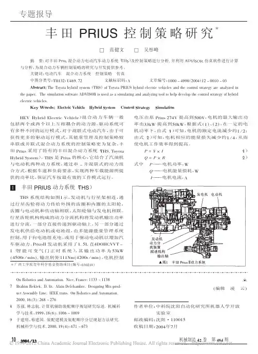
栏目编辑:刘玺lx@motorchina.c o m礞N e w Car Tech新车新技术丰田THS-M混合动力核心控制策略介绍(二)♦/江苏田锐(接上期)逆变器是一种把直流电转换成交流电或反之亦然的装置,为 了使直流逆变产生交流,需要将4个不同的开关(图14),从S1到 S4,按如下方式组合,改变开关的开/关时间可以相应的改变频率。
驱动电动机需要产生正弦交流电压,产生正弦波形交流而不 是矩形波形交流则需要持续改变电压以产生正弦波。
如图15所 示,当检测到所需输出电压(V i)持续极短的一段时间时(Ts)。
通 过控制“Ton”(Ton,开关O N时间)时间,使“Vi x Ts”的面积和“Vd x Ton”(电源电压x开关O N时间)的面积相同,则有效电 压即变为V i。
通过此方式控制逆变器电路中IGBT的通断时间,使 产生的电压持续改变,从而模拟产生出正弦交流电压。
这种控制 方式的全称是Pulse W idth M odulation(即:P W M脉冲宽度调 制),它是用脉冲宽度按正弦规律变化和正弦波等效的PW M波形 控制逆变器电路中IGBT的通断时间,使其输出的脉冲电压的面积 与所希望输出的正弦波在相应区间内的面积相等,从而达到驱动 电动机所需的交流输出电压。
动力管理控制ECU(HV C PU)根据 车辆的工作条件,通过改变调制波(图16)的频率和幅值则可调节 逆变器电路输出电压的频率和幅值,以有效控制M G1和M G2,由此,确保最大效率的控制不同工况下电动机的扭矩和转速。
简而 言之,它是通过改变输出方波的占空比来改变等效的输出电压,为 了让电动机获得更大的扭矩输出,正弦波形的三相交流的振幅(电 流)应该增加,为了使电动机的速度增加,正弦波形三相交流的频 率应该增加(图17)。
图16调制波示意图调制波可分为3种:正弦波PW M、可变PW M和矩形波(1个脉 冲)。
正弦波PW M是最常用的电压波形,电压和电流成正弦波,转 矩变化小,可以获得较为平滑的输出,多用于电动机的低速范围。
控制计划(中英⽂标准模板)Techniquece47±10-300mm(0.02)深度尺Depth Gages⾸末检1件、巡检5件、⾃检5件first and end inspection 1pcs,inspection 5pcs,self-inspection 5pcs⾸末检1次、巡检每2⼩时、⾃检每1⼩时first and end inspection 1,inspection every 2hrs,self-inspection every hrs标识、隔离、检查模具Identification ,Separate ,Checkthe die B-1压⼒Pressure◇上缸Cylinder 15(+1,0)Mpa下缸Undercylinder9(+1,0)Mpa⽬视Visual1每班Every shift调整设备、上报Adjustment equipment ,reportingφ142.5(+0.2,-0.3)0-150mm(0.02)游标卡尺A-3◇47±10-300mm(0.02)深度尺Depth Gages⾸末检1件、巡检5件、⾃检5件first and end inspection 1pcs,inspection 5pcs,self-inspection 5pcs⾸末检1次、巡检每2⼩时、⾃检每1⼩时first and end inspection 1,inspection every 2hrs,self-inspectionevery hrs标识、隔离、检查模具Identification ,Separate ,Checkthe die B-1压⼒Pressure◇上缸Cylinder 15(+1,0)Mpa下缸Undercylinder9(+1,0)Mpa⽬视Visual1每班Every shift调整设备、上报Adjustment equipment ,reportingφ214±0.50-300mm(0.02)游标卡尺Calipers6×φ8.7±0.250-150mm(0.02)游标卡尺Calipers A-4◇HDJ-H0001检具Gage⾸末检1件、巡检5件、⾃检5件first and end inspection 1pcs,inspection 5pcs,self-inspection 5pcs末检1次、巡检每2⼩时、⾃检每1⼩时first and end inspection 1,inspection every 2hrs,self-inspectionevery hrsφ205±0.750-300mm(0.02)游标卡尺Calipers 深度Depth检验记录Inspection record50整形ShapingJY32-315/315T油压机Hydraulic Press 直径Diameter ⾸末检1件、巡检3件、⾃检3件first and end inspection 1pcs,inspection 3pcs,self-inspection 3pcs ⾸末检1次、巡检每4⼩时、⾃检每1⼩时first and end inspection 1,inspection every 4hrs,self-inspectionevery hrs 检验记录Inspection recordHD134-H014/整形模Shaping Die⾼度Height检验记录Inspection record标识、隔离、检查模具Identification ,Separate ,CheckHD146-H011/切边冲孔模Trimming and Punching die位置度Location degreeJA21-160/160T冲床Presses深度Depth直径Diameter 检验记录Inspection record标识、隔离、检查模具Identification ,Separate ,Checkthe die40冲压拉深成形Punch冲压切边冲孔Trimming and PunchingJB21-160B-SM/160T冲床直径Diameter⾸末检1件、巡检3件、⾃检3件first and endinspection⾸末检1次、巡检每4⼩时、⾃检每1⼩时first and end inspection60⾸末检1件、巡检3件、⾃检3件first and end inspection 1pcs,inspection3pcs,self-inspection 3pcs⾸末检1次、巡检每4⼩时、⾃检每1⼩时first and end inspection 1,inspection every 4hrs,self-inspection every hrsTechnique ce10(+2,0)0-300mm(0.02)⾼度尺Height Gages85°±0.5°0-360°(2′)万能⾓度尺Universal angle rulerA-5◇⾸末检、巡检0-10mm(0.01)百分表/⾃检 0-1mm塞尺First and endinspection 0-10mm(0.01) Dialindicator/Self-inspection 0-1mmFeeler⾸末检1件、巡检5件(X-R图)、⾃检5件first and endinspection1pcs,inspection 5pcs(X-R末检1次、巡检每2⼩时、⾃检每1⼩时first and end inspection1,inspection every2hrs,self-inspection everyhrsφ4(+2,-1)0-150mm(0.02)游标卡尺Calipers1±0.250-300mm(0.02)⾼度尺Height Gages90⽆油污No dirt⽬测Visual全检Fullinspection每批per lot检验记录Inspectionrecord标识、隔离、退货Identification , Separate ,Reject 喷塑⽓压Spraypressure0.4-0.5MPa喷塑电压Spray voltage50-60KV烘烤温度Bakingtemperature180-200℃烘烤时间Baking time30-40min⽆漏喷No leakage jet⽬测equipment ,reporting100喷塑SprayXNG-36-1B/粉末喷涂⽣产线Powder coatingproduction lines⽬测Visual1产线外观Appearance全检Fullinspectionper lot70冲压翻边成形FlangingJB21-160B-SM/160T冲床Presses件、⾃检3件first and endinspection1pcs,inspection3pcs,self-inspection 3pcs时、⾃检每1⼩时first and endinspection1,inspection every4hrs,self-inspectionevery hrs80冲压压字Pressure logoJA21-160/160T冲床Presses孔径diameter I.D.⾸末检1件、巡检3件、⾃检3件first and endinspection1pcs,inspection3pcs,self-Separate ,Checkthe die⾓度AngleHD124-H008/翻边模Flanging die平⾯度Flatness⾼度Height标识、隔离、检查模具Identification , Separate ,Checkthe die HD150-H006/压字模Pressure logodie(E32629-3)HD150-H005/压字模Pressure logodie(E32629-1)⾼度Height检验记录Inspectionrecord⾸末检1次、巡检每4⼩时、⾃检每1⼩时first and endinspection1,inspection every4hrs,self-inspectionevery hrs检验记录Inspectionrecord外观Appearance外协镀锌Outsourcing galvanized检验记录Inspectionrecord每班Every shift检验记录Inspectionrecord台⾯,上⾯压5kg物体)/0.15mm feeler ( cover flat on the marble countertops, pressure 5kg objects above )盐雾试验≥1000⼩时/Salt spray test≥1000hrs盐雾腐蚀试验机/Salt spray corrosiontest machine3每季度Each quarter盐雾试验报告Salt spray testreport110丝印完整Full screen⽬测Visual全检Fullinspection每批per lot检验记录Inspectionrecord标识、隔离、退货Identification ,Separate ,Reject A-3◇47±10-300mm(0.02)深度尺Depth Gages10A-4◇HDJ-H0001检具Gage10A-5◇0.15mm塞尺(端盖平放在⼤理⽯台⾯,上⾯压5kg物体)/0.15mm feeler (cover flat on themarble countertops, pressure 5kg objectsPackaging Specifications点数Counting2箱2 box标识、隔离、返⼯Identification , Separate ,Rework清晰Clear⽬测Visual包装规范Packaging Specifications⽬测Visual物资发货单Material Invoice点数Counting标识、隔离、返⼯Identification , Separate ,Rework 平⾯度Flatness防腐蚀性能Corrosion100喷塑SprayXNG-36-1B/粉末喷涂⽣产线Powder coating production lines全检Fullinspection每批per lot外协丝印Outsourcing Screen外观Appearance检验记录InspectionrecordSampling inspection and packaging 标识、隔离、处理Identification ,Separate ,Dealwith位置度Location degree平⾯度Flatness数量Quantity每批per lot检验记录Inspectionrecord标识Label标识、隔离、返⼯Identification ,Separate ,Rework包装Package数量Quantity130⼊库&出货Warehousing & shipping全检Fullinspection每批per lot物资发货单Material Invoice。
第14单元课文C 丰田普瑞斯轿车混合动力系统1.工作原理丰田已经生产了世界上最早的批量生产的混合动力轿车。
混合动力系统是汽车未来的希望,现在对购置混合动力汽车将得到更多的激励。
普瑞斯或者其它任何一种汽油电动混合动力汽车的拥有者都将有资格得到联邦政府的所得税减税。
根据国内税务局的规定,混合动力汽车有资格获得适用于清洁燃料汽车的长期减税。
这项政策还允许消费者在车辆初次投入使用的那一年申请给与一次性减税。
混合动力系统的最简单的形式就是将内燃机与电动机的最好的工作特性结合起来,而最复杂的混合动力系统(如丰田的混合动力系统)将回收制动器中损失掉的能量,并利用这些能量来补充内燃机的动力。
这些复杂的技术使丰田混合动力系统取得了优异的燃油经济性和大幅度降低CO2。
丰田普瑞斯在2001年刚刚发布时,就被选为世界上设计最好的轿车。
之所以这样,是因为该车是能够容纳4到5人和他们所携带的行李的最早的混合动力汽车。
该车也是能够买到的最经济且最环保的车辆之一。
2004年,第二代普瑞斯赢得了声望很高的《汽车趋势》年度车型奖。
第二代普瑞斯轿车中的丰田混合动力系统(THS-Ⅱ)的EPA(美国环保局)燃油经济性数字给人以深刻印象——城市循环为60英里/加仑(3.9L/100km),公路循环为51英里/加仑(4.6L/100km),并且满足了AT PZEV(先进技术部分时间零排放车辆)的规格。
混合动力系统的主要部件有内燃机、电动发电机1(MG1)、电动发电机2(MG2)、行星齿轮机构、变换器、HV(高压)蓄电池和HV ECU,见图14-6和图14-7。
1NZ-FXE 1.5L汽油发动机采用了VVT-i可变气门定时系统和ETCS-i电子节气门控制系统。
电动发电机1(MG1)用作功率分流行星齿轮机构的控制元件。
它还用来提供驱动电动发电机2(MG2)所需的电功率。
MG1有效地控制着变速驱动桥的无级变速器功能,并充当了发动机起动机。
在低速时,MG2提供驱动力,而在高速时,则提供补充的驱动力。
丰田案例14项原则《完整版》第一部分 丰田模式具有世界一流的效能第一章 越的操作流程为战略性武器我们最重视的是确实执行与采取行动。
我们所不了解的事情很多,因此,我们总是要求员工:何不采取行动,尝试不同的方法呢?当代诚实面对自己的失败时,才会了解自己所知甚少,你可以矫正那些失败,再做一次,在第二次的尝试中,你发现了另一个错误或你不满意的事,然后,你可以再尝试。
于是,通过不断改进,或者应该说是靠不断尝试的行动以获得改进,就能提升实务与知识。
`——丰田汽车总裁张富士夫,2002年丰田汽车公司最早引起世界注目的是在20世纪80年代,当时情况明显显示,日本企业及其产品的品质和效率确有独到之处,日本制造的汽车比美国汽车耐用,需要的维修明显较少。
到了20世纪90年代,更明显的迹象显示,相较于其他日本汽车制造商,丰田汽车公司显然更特别、突出。
这并非指它的汽车设计或性能令人赞叹(尽管这是事实,丰田车开起来流畅顺手,其设计也多半非常精致),而是丰田汽车的工程与制造模式实现了令人难以置信的流程与产品的一致性。
丰田的汽车设计更快速,可靠性更高,同时,即使在日本汽车业劳动力工资水准相对较高的情况下,丰田仍然得以维修极具竞争力的汽车制造成本。
令人印象深刻的另一点是,每当丰田出现明显弱点、似乎将不敌竞争时,它总是能奇迹般地解决问题,并且以更强壮之势卷土重来。
今天,丰田已是全球第二大汽车制造商,仅次于通用汽车公司,在全球170个国家的年汽车销售量超过600万辆,但是,丰田比全世界任何汽车制造商都要赚钱。
汽车业分析师预估,若以现在的趋势持续下去,丰田汽车的全球销售量最终会超越通用汽车,而成为全世界最大的汽车制造商。
汽车业界的每一个人,心脏许多消费者,都熟知丰田的显著成就与世界一流品质:丰田汽车公司在2003年3月底结束的会计年度,获利81.3亿美元,比通用、克莱斯勒、福特3家公司的获利总和还要高,同时也是过去10年所有汽车制造商中年度获利最高者。
汽车automobile 1TOYOTA丰田汽车缩略语AAP Auxiliary Acceleration Pump 辅助加速泵ABV Air By-Pass Valve 空气旁通阀ABS Auti-Lock Brake System 防抱制动系统A/C Air Conditioner 空气调节器ACSD Automatic Cold Start Device 自动冷起动装置A.D.D Automatic Disconnecting Differential 自动断开差速器AI Air Injection 空气喷射AS Air Suction 进气A/T Automatic Transmission 自动变速器ATF Automatic TranSmission Fluid 自动变速器用油ATDC After Top Deal Center 上止点之后B0 Overdrive Brake 超速制动器B1 NO.1 Coast Brake 第二滑行制动器B2 NO.2 Brake 第二制动器B3 NO.3 Brake 第三制动器BDC Botton Dead Center 下止点BTDC Before Top Desd Center 上止点前C0 Overdrive Direct Clutch 超速直接离合器C1 Front Clutch 前离合器C2 Rear Clutch 后离合器CB Circuit Breaker 断路器CB Choke Breaker 阻风门适度开启阀CMH Cold Mixture Heater 冷混合加热器DP Dash Pot 减速缓冲器ECT Electronic Controlled Transmission 电子控制变速器ECU Electronic Controlled Unit 电子控制装置EFI Eleclronic Fuel Injection 电子控制喷油装置EGR Exhaust Gas Recirculation 废气再循环ELR Emergency Locking Retractor 紧急锁紧收缩装置ESA Electronic Spark Aduance 电子点火提前(装置)EVAP Fuel Evaporative Emission System 燃油蒸发污染控制系统EX Exhaust 排气F0 Overdrive One-way Clutch 超速单向离合器F1 No.1 One-way Clutch 1号单向离合器F2 No.2 One-way Clutch 2号单向离合器FIPG Fast Idle Cam Breaker 快怠速凸轮开关FIPG Formec in Place Gasket 密封材料FL Fusible Link 熔断丝FR Front 前部HAI Hot Air Intake 自动调温式空气滤清器系统HIC Hot Idle Compendent 热怠速波动补偿HAC Hight Altitude Compensator 高海拔补偿装置IFS Independent Front Suspension 独立前悬挂HA Inlegrated Ignition Assemgly (分电器点火线圈)一体化的点火装置IN Intake 进气IRS Independent Rear Suspension 独立后悬挂ISC Idle Speed Control 怠速控制(系统)LH Left-hand 左手边LHD Left-hand Drive 左座驾驶LSD Limited Slip Differential 防止滑动差速器LSPV Load Sensing Proportioning Valve 负荷传感比例阀LSP&BV Load Sensing Proportioningand By-pass Valve 负荷传感旁通和比例阀LST Load Sensing Timer 载荷传感定时器MAS Mixture Adjusting Screw 混合调整螺丝MAX Maximum 最大MP Multipurpose 多用途M/T Manual Transmission 手动变速器O/D Overdrive 超速OPT Option 选购(自行决定)O/S Oversize 加大(修理)尺寸OVCV Outer Vent Control Valve 外通风控制阀PCV Positive Crankcase Ventilation 曲轴箱强制通风装置PPS Progressive Power Steering 渐进式动力转向机构PS Power Steering 动力转向RBS Recirculating Ball-type Steering 循环球式转向器RH Right-Hand 右手边RHD Right-Hand Drive 右座驾驶SSM Special Service Material 特种维修材料SST Special Service Tools 特种维修工具STD Standard 标准S/W Switch 转换开关T Tightening Torgue 扭紧力矩TCCS Toyota ComputerControlled System 丰田汽车(发动机)微电脑集中控制系统TDC Top Dead Center 上止点T/M Transmission 变速器TP Throttle Positioner 节气门位置控制阀VCS Vacuum Control Switch 真空控制开关VSV Vacuum Switching Valve 真空转换阀VTV Vacuum Transmitting Valve 真空(负压)延迟阀W/ With 带(有)W/O Without 不带2WD Two Wheel Drive Vehicles (4×2) 2轮驱动4WD Four Wheel Drive Vehicles(4×4) 4轮驱动AIR CLEANER 空气滤清器阻塞警示器BEAM 前照灯远光指示灯BELT 乘员座椅安全带警示灯CHARGE 蓄电池充电指示灯DOOR 车门警示灯EXHBRAKE 排气制动指示灯FILTER 柴油滤清器警示灯FUEL 燃油表GLOW 预热指示灯LIGHTS 灯光故障警示灯ODOMETER 里程表SPEEDOMETER 车速表T.BELT 正时或同步皮带指示灯TACHOMETER 发动机转速表TEMP 水温表TRIPMETER 单程里程计VAC 真空警示灯WATER 发动机冷却液液位警示汽车automobile 2汽车类Automobile整车Finished Automobile轿车Passenger Car休旅车Recreational Vehicle (RV)小型商用车(3.5吨以下) Light Duty Commercial Car (Less Than 3.5 Tons) 大型商用车(3.5吨以上) Heavy Duty Commercial Car (More Than 3.5 Tons)散装车Bulk Truck搅拌车Mixer Truck环境卫生车Garbage Truck液罐车Refueling Truck倾卸车Dumper Truck曳引车Tractor Truck消防车Fire Fighting Truck堆高机Forklift拖板车Pallet Truck运钞车Armor Cash Carrier冷气客车Air-Conditioned Car冷冻车Freezer Car拖车Trailer车体打造(改装) Car Body Building (Refitting)瓦斯车LPG Car底盘车Chasis Truck引擎零件Engine Parts引擎Engine引擎波司Engine Bush引擎修理包Engine Gasket Kits引擎零件Engine Parts凸轮轴Camshaft凸轮轴链轮Sprocket Camshaft皮带张力器Tensioner曲轴Crankshaft曲轴皮带盘Crankshaft Pulley曲轴轴承片Crankshaft Bearing汽门Valve汽门座Valve Seat汽门摇臂Valve Arm汽门摇臂盖Rocker Cover汽门弹簧Valve Spring汽门导管Valve Guide汽缸头(盖) Cylinder Head汽缸衬套Cylinder Liner汽缸体Cylinder Block波司垫片Washer活塞Piston活塞肖Piston Pin活塞环Piston Ring活塞衬套Piston Liner飞轮Flywheel飞轮环齿轮Ring Gear of Flywheel 时规炼条/皮带Timing Chain/Belt连杆Connecting Rod连杆轴承片Connecting Rod Bearing 摇臂轴Rocker Arm Shaft汽门锁Valve Cotter止推垫片Thrust Washer共鸣箱Resonator喷油嘴Injection Nozzle燃料系统Fueling System油箱Fuel Tank油箱浮筒Gauge Fuel Tank空气滤清器Air Cleaner空气滤清器盖Air Cleaner Cover空气滤清器导管Air Intake Tube空气滤蕊Air Cleaner Element消音器Exhaust Muffler排气歧管Exhaust Manifold排气管Exhaust Pipe进气歧管Intake Manifold节流阀Throttle Valve燃油管Fuel Pipe燃油帮浦Fuel Pump燃油滤清器Fuel Filter触媒转化器Catalytic Converter柴油车黑烟净化器Diesel Particulate Filter 时规炼条/皮带外盖Timing Chain/Belt Cover 燃料系统Fueling System废气回收管EGR Tube冷却系统Cooling System水箱Radiator水管Water Hose水箱水管Radiator Hose水帮浦Water Pump水箱风扇Radiator Fan风扇Fan副水箱Auxiliary Radiator节温器Thermostat调节器Regulator水箱支架Radiator Mounting冷却系统Cooling SystemA/C风扇A/C Fan润滑系统Lubrication System油底壳Oil Pan自排车用滤油器Oil Filter for Automatic Transmission机油尺Oil Level Gauge机油帮浦Oil Pump机油滤清器Oil Filter机油滤网Oil Strainer润滑系统Lubrication System机油尺导管Oil Level Gauge Tube 空调系统Air-conditioning System冷气总成A/C Assembly冷气配管A/C Hose冷气导风管A/C Duct冷气压缩机A/C Compressor冷凝器A/C Condenser暖气总成Heater Assembly鼓风机Blower Assembly蒸发器Evaporator冷媒管A/C Pipe储液瓶A/C Receiver空调相关零件A/C Related Components 空气清净机Air Purifier空调滤网A/C Filter空调系统Air-conditioning System提速器Actuator车身钣金件Body & Stamping Parts引擎支撑Engine Mounting引擎盖Engine Hood车身Car Body车门Door Panel车顶板Roof底盘及其另件Chassis and Related Parts 底盘车架Frame门框Sash保险杆Bumper钣金件Stamping Parts叶子板Fender横梁Cross Member行李箱盖Trunk Lid车柱Pillar车身钣金件Body & Stamping Parts 支架Bracket补强板Reinforcement Plate底盘系统Chassis System下臂Lower Arm上臂Upper Arm手? x车拉柄Parking Brake Lever支柱总成Strut Assembly方向盘Steering Wheel比例阀Proportional Valve主轴、副轴Mainshaft / Countershaft 平衡杆Stabilizer Bar扭力杆Torsion Bar? x车分泵Brake Cylinder? x 车来令片Brake Lining Shoe? x车油管(软) Brake Hose? x车油管(硬) Brake Tube? x车真空倍力器Brake Vacuum Booster ? x车总泵Brake Master Cylinder后轴总成Rear Axle Assembly动力方向系统Power Steering System 动力转向油管Power Steering Hose 动力转向帮浦Power Steering Pump 控制拉线Control Cable排档杆Shift Lever排档头Knob球形接头Ball Joint等速接头 C.V. Joint传动轴Propeller Shaft叶片弹簧Leaf Spring鼓、碟式? x车器Drum / Disc Brake Assembly鼓式? x车盘Brake Drum碟式? x车盘Brake Disc辅助气囊Air Bag踏板Pedal齿轮Gear横拉杆接头Tie-Rod End螺旋弹簧Coil Spring避震器Shock Absorber转向连杆Steering Linkage转向节臂Knuckle转向齿轮箱Steering Gear Box转向机柱Steering Column转向总成Steering Assembly离合器分泵Clutch Cylinder离合器片Clutch Disc离合器外壳Clutch Case离合器总成Clutch Assembly离合器总泵Clutch Master Cylinder离合器释放轴承Clutch Release Bearing变速箱Transmission Box变速箱外壳Transmission Case曳力杆Trailing Arm避震器前后活塞杆Piston Rod of Front and Rear Shock Absorber 底盘系统Chassis System自排变速箱修理包Automatic Transmission Gasket Kits齿条Gear Rack? x车真空管Brake Boost Vacuum Tube车轮系统Wheeling System轮毂Wheel Hub轮胎Tire轮胎汽门嘴Tire Valve轮圈Wheel Disk轮圈盖Wheel Cover内胎(含内衬) Inner Tire (Flap)车轮系统Wheeling System电装品Electrical Parts电瓶Battery中央门控Central Door Lock分电盘Distributor火星塞Spark Plug汽车用电子钟Digital Clock汽车音响Car Audio防盗器Car Burglar Alarm雨刷及雨刷连杆Wiper / Linkage保险丝座Fuse Seat保险丝Fuse洗涤壶Windshield Washer配线Wire Harness马达类Motor高压线组Ignition Cable喇叭Horn发电机(零件) Alternator (Components) 开关类Switch蜂鸣器Buzzer预热塞Glow Plug仪表Combination Meter灯泡Bulb灯类Lamp点火线圈Ignition Coil继电器Relay倒车雷达Reverse Sensor电池充电器Battery Charger闪光器Flasher省电器Energy Saving Unit端子Terminal电动座椅装置Power Seat Unit马达零件Motor Components电装品Electrical Parts汽车用光盘Car CD 汽车用液晶显示器Car LCD调整器Regulator整流器Rectifier电子点火器Ignition Module倒车显示器Rear View Display定速器Cruise ControllerHID车灯安定器组合HID Ballast Complete Set for HeadlightsLED灯LED Lamp车灯控制器Lighting Controller点火线圈模块Ignition Coil Module外装品Exterior Parts水箱饰罩Radiator Grille天线Antenna车身护条Side Protector防撞护垫Bumper Pad后视镜Door Mirror装饰贴纸、标志Ornament Mark轮弧Fender Trim挡泥板Mud Guard扰流板Spoiler前防撞杆Guard Assy (Front)后防撞杆Grard Assy (Rear)外装品Exterior Parts内装品Interior Parts仪表板Instrument Panel中央置物箱Console孔塞Grommet Plug地毯Floor Mat安全带Seat Belt车门扶手Door Armrest车门把手Door Handle车门锁Door Lock车顶内衬Roof Lining车窗升降摇柄Window Lifter Handle 车窗升降机Window Lifter防水衬条Weatherstrip油量表Fuel Gauge门饰板Door Trim室内镜Room Mirror音响喇叭盖Speaker Cover(电动)座椅( Electric) Seat顶蓬Headlining烟灰缸Ashtray各类隔音垫All Kinds of Silencer饰板/饰条Garnish / Trim仪表饰板Instrument Panel Garnish 遮阳板Sunvisor 压条Moulding点烟器Cigar Lighter备胎板Trim for Spare Tire天窗Sun Roof后置物板Rear Parcel Shelf后舱室饰板Rear Trunk Trim内装品Interior Parts仪表板支架Instrumental Panel Mounting其它Others随车工具Tools千斤顶Jack尼龙绳、特多龙绳Nylon Rope生产、检测及涂装设备Production,Test & Painting Equipment各类孔盖Cap、Cover扣具Cargo Lash夹片、管束Clamp, Clip油土与基准模型Clay Model and Master Model油封Oil Seal门铰链Door Hinge故障标志Reflector玻璃类Glass修理业Repairing & Maintenance粉末冶金Powder Metallurgy轴承Bearing塑料件Plastic Parts隔热材Heat Insulator电子件Electrical Parts垫片类Seal、Gasket、Washer、Packing碳刷Carbon Brush管类Pipe, Hose, Tube铜套类Bushing弹簧Spring模、夹、治、检具Die, Fixture, Jig, Checking Gauge 橡胶件Rubber Parts帮浦类Pump螺帽/螺栓/螺丝Nut/Bolt/Screw锻造件(加工) Forging Parts (Processing)滤清器类Filter锁Lock镜类Mirror铸造件(加工) Casting Parts (Processing)引擎盖铰链Hinge of Engine Hood行李箱铰链Hinge of Trunk Lid保险杆支撑Mount of BumperCAD/CAM 车身设计CAD/CAM Car Body Design汽车清洁保养用品Cosmetics for Automobile 涂料Paints合成木材Synthetic Wood电磁阀Solenoid Valve热水阀Heater Valve冷煤电磁阀Refrigerate Solenoid valve玻璃滑槽Glass Run双面胶带Acrylic Foam Tape触媒转换器缓冲绵Catalytic Converter Mate 黑烟过滤器Diesel Particle Filter车用灭火器Extinguisher零组件用材料Components Materials汽车用行动电话Car Hand-free Mobile Phone 汽车保全系统Car Security System汽车导航系统Car Navigation System人造革Artificial Leather铭板Nameplate汽车用计算机Car Computer无线电胎压侦测仪Wireless Tire Monitor汽车内装用牛皮Leather for Car Interior打蜡机Buffer (Car Polisher)金属表面处理(材料) Metal Surface Treatment (Material)插接件Connector Clip胎压不足警示器Tire Low Pressure Indicator 温度感应器Water Temperature Sensor油压感应器Oil Pressure Sensor机油Engine Oil自动变速箱油Automatic Transmission Oil 油品添加剂Oil Additive热处理Heat Treatment自行车类Bicycle整车Finished Bicycle一般自行车Regular Bicycle三轮车Tricycle协力车Tandem Bicycle城市车ATB孩童车Junveniles Bicycle室内运动车(健身车) Exerciser单轮车Unicycle无链式自行车Chainless Bicycle登山车Mountain Bicycle越野车Trekking Bicycle跑车(自由车)Racing Bicycle电动自行车Electrical Bicycle折叠式自行车Folding Bicycle海滩车Beach Bicycle( 电动)滑板车( Electric) Kick Board Scooter其它特种自行车Other Special-purpose Bicycles 避震脚踏车Suspension Bicycle传动件Transmission曲柄组Chainwheel & Crank飞轮Flywheel链条Chain变速杆Shift Lever变速器Derailleur电动自行车马达Electric Bicycle Motor电动自行车控制器Electric Bicycle Driver齿轮箱Gear Box车轮及? x车Wheel and Brake轮胎Tire夹式? x车器Caliper Brake快拆Quick Release花鼓Hub & Free Hub液压式? x车器Hydraulic Brake脚? x车器Coaster Brake碟式? x车器Disk Brake轮圈Rim辐条/辐帽Spoke/Nipple悬臂式? x车器Cantilever Brake控制拉线Control Cable? x车来令片Brake Lining Shoe 配件Accessories铃Bell反光片Reflector水壶架Bottle Cage打气筒Floor Pump商标贴纸Sticker货架Luggage Carrier速度表Speed Meter喇叭Horn电灯Dynamo / Lighting Set 辅助轮Training Wheel挡泥板Mud Guard / Fender 头盔Helmet锁Lock链盖Chain Cover篮Basket 后视镜Rear Mirror车体Body车架Frame把手Handle Bar中轴组件(天心)Bottom Bracket Parts 车手带Handle Strap车头组件Headset前叉Front Fork前叉肩Fork Crown后叉端Rear Fork End座杆Seat Post座杆束Seat Post Clamp停车支架Kickstand接头Lug & Shell辅助把手Bar End竖管Stem螺帽/螺栓/螺丝Nut/Bolt/Screw避震前叉Suspension Fork避震器Shock Absorber三通管3- way Pipe五通管5- way Pipe车架材料Frame Materials其它Others座垫Saddles水壶架Bottle Cage夹器固定座Pivot定趾器Toe Clip闪光灯Flasher趾夹带Toe Strap把手套Grip塑料件Plastic Parts脚踏板Pedal碳刷Carbon Brush弹簧Spring轮圈盖Wheel Cover锻造件(加工) Forging Parts (Processing)导线Cable模、夹、治、检具Die,Fixture,Jig & Checking Gauge橡胶件Rubber Parts生产、检测及涂装设备Production,Test & Painting Equipment座垫套Saddle Cover涂料Paints充电器Charger温度记录器Temperature Recorder电池容量计Battery Capacity Indicator电动自行车电路设计Electric Bicycle Circuit Design 电动自行车电池组Electric Bicycle Battery Set机车类Motorcycle整车Finished Motorcycle50CC以下机车Less Than 50CC Motorcycle50~150CC机车50~150 CC Motorcycle150CC以上机车More Than 150CC Motorcycle残障专用车Motorcycle for Handicap电动机车Electric Motorcycle其它电动辅助车辆Other Electric Auxiliary Vehicles多功能休闲车ATV引擎零件Engine Parts汽缸Cylinder化油器Carburetor引擎Engine引擎零件Engine Parts引擎盖Engine Cover水箱Radiator火星塞Spark Plug凸轮Cam凸轮轴Camshaft凸轮轴链条Cam Chain凸轮链条张力器Cam Chain Tensioner曲轴Crankshaft曲轴箱Crankcase曲轴箱盖Crankcase Cover汽门Valve汽门座Valve Seat汽门导管Valve Guide汽缸头Cylinder Head汽缸头侧盖Cylinder Head Side Cover 油帮浦Oil Pump后轮驱动座Rear Wheel Drive Seat活塞Piston活塞肖Piston Pin活塞环Piston Ring连杆Connecting Rod涡轮增压器Turbo-Supercharger脚踏起动机杆Kick Starter齿轮变速零件Gear Shift Parts机油冷却器Oil Cooler离合器Clutch离合器座Clutch Plate离合器杆Clutch Lever变速箱Transmission Box油管Fuel Pipe汽门锁Valve Cotter火星塞盖Plug Cover 齿轮衬套Gear Bushing曲轴肖Crank Shaft Pin炼条调整器Tensioner节流阀Throttle Valve离合器来令片Clutch Lining齿轮轴Gear Axle马达轴Motor Axle传动轴Transmission Axle车体及电装Body and Electrical Parts灯类LampC.D.I.总成 C.D.I. Unit Assembly工具Tool中心盖Center Cover反光片Reflector引擎罩盖Air Shroud / Cylinder方向把手Steering Handle主滑动模轮组件Primary Sheave Assembly主脚架Main Stand交流发电机(零件) A.C. Generator (Components) 行李箱Luggage Box冷却风扇Cooling Fan把手盖Handle Cover车架Frame车体盖Body Cover拉杆Handle Lever油杯Fuel Cup Assembly油箱Fuel Tank空气滤清器Air Cleaner? x车来令片Brake Shoe? x车鼓Brake Drum? x车盘Brake Disk? x车踏板Brake Pedal? x车总成Brake Assembly前叉Front Fork前叉顶梁Fork Top Bridge前护盖Front Fender后视镜Back Mirror后悬吊系统Rear Suspension 风扇盖Air Shroud飞轮Flywheel座垫Seat侧脚架Side Stand侧盖Side Cover 排气消音器Exhaust Muffler后架Carrier喇叭Horn无段自动变速系统 C.V.T.发电机Alternator传动轴总成Secondary Sheave Assembly 摇臂Rocker Arm煞车踏板Brake Pedal节流把手Throttle Grip脚踏板Board / Footrest脚踏杆Kick Crank Assembly电圈Starter电瓶Battery配线Wire Harness碳刷Carbon Brush仪表Meter调整器Regulator轮胎Tire轮圈Wheel Disk轮毂Wheel Hub导线Cable挡泥板Fender机车链轮Chain灯泡Bulb燃油滤清器Fuel Strainer Assembly避震器Shock Absorber点火线圈Ignition Coil转向主干Steering Stem Comp链条Chain链条盖Chain Case继电器Relay触媒转化器Catalytic Converter排气管Exhaust Pipe吊架Hanger控制拉线Control Cable活性碳罐Canister油箱浮筒Tank Float机油浮筒Oil Float档位调整器Gear Position Indicator端子Terminal电动机车控制器Electric Motorcycle Driver把手座Grip Holder马达类Motor马达零件Motor Components避震器前后活塞杆Piston Rod of Front and Rear Shock Absorber其它Others油封Oil Seal 舌簧阀Reed Valve钣金件Stamping Parts防盗器Burglar Alarm闪光器Flasher贴纸Sticker轴承Bearing开关类Switch塑料件Plastic Parts电子件Electrical Parts垫片Gasket管类Tube or Pipe弹簧Spring模、夹、治、检具Die, Fixture, Jig, Checking Gauge 辐条/辐帽Spoke/Nipple齿轮Gear橡胶件Rubber Parts帮浦类Pump螺帽/螺栓/螺丝Nut/Bolt/Screw锻造件(加工) Forging Parts (Processing)滤清器Filter铸造件(加工) Casting Parts (Processing)锁Lock生产、检测及涂装设备Production,Test & Painting Equipment铭板Name Plate油土及基准模型Clay Model and Master Model地毯Carpet涂料Paints握把Grip置物袋Carriage Bag机车座垫用牛皮Leather for Motorcycle Seat铁路车辆类Railroad Vehicle铁路车辆制造及修理Railroad Vehicle Manufacture & Repair铁路车辆零件Railroad Vehicle Parts铁路扣夹Clip for Railroad橡胶件Rubber Parts轮椅升降机Wheel chair lift图例legend工位station吊运装置overhead hoist更衣室restroom 1号厂房工艺布置方案图proposal of the Plant I layout合笼mate底盘平移台chassis shuttle车辆转移台bus transfer前围角板front wall angle cover后围侧板rear wall side cover 保险杠bumper三类底盘three type chassis左侧围应力蒙皮R/S stretching skin (road side) 中涂floating coat拼装台collector切割轮口wheel -arch cutting内饰trim线束harness返工re-doing轮罩护板wheel house发车前准备pre-delivery举升hoist小批量产品be pilot 2套two kits配电站power transformer substation裙板skirt发动机托架engine holding frame诊断报警系统diagnosis and alarming system 互换性interchangeability缩微图纸microfiche files总装final assembly磷化phosphating仪表板dash board切齐trimming结构完整性structure integrity自动愈合的防腐材料self-healing corrosion preventative material长途客车inter-city bus改装厂refitting factory遮阳板sun visor随车工具tool box钢化玻璃toughened grass异形钢管special steel pipe全天候空调系统full range A/C强制通风ram-air ventilation停机时间downtime无公害柴油clean diesel宽敞悬臂式座椅roomy cantilevered seat防滑地板no-skid floor织物纹里铝合金textured aluminum extrution爬坡能力grade ability排水阀drain valve除湿器moisture ejector怠速时at idle琴式驱动桥banjo type drive axle通风口duct恒温控制thermostatic control平衡水箱surge tank 变光开关simmer switch消音器muffler防破坏vandal resistant聚碳化透镜poly-carbonate len镀锌板galvanized plate搭接lap亮丽的外表smart apperance隐藏式固定concealed fastening水洼ponding发动机中置式客车bus with under floor engine 组合式客车车身modular bus body薄壳式结构shell construction衬垫pad空气导流板air deflector搁梁shelf beam腰梁waist rail梭梁stabilizing beam腰带式安全带diagonal safety belt压条trim strip嵌条insertion strip翼板fender斜撑bracing piece转向盘回正性试验test of steering wheel returnability转向盘转角脉冲试验steering wheel impulse input test转向盘转角阶跃输入试验steering wheel step input or transient state yaw response test极限侧向加速度试验limiting lateral acceleration test汽车平顺性随机输入行驶试验automobile ride random input running test汽车平顺性单脉冲输入行驶试验automobile ride single pulse input running test汽车悬挂系统固有频率与阻尼比的测定试验measurement of natural frequency and damping raito of suspension功率突然变化影响试验test of effect of sudden power change收油门后控制试验test of control at breakway横风稳定性试验test of crosswind stability反冲试验kick-back test轮胎爆破响应时间试验test of burst response of tyre绕过障碍物试验obstacle avoidance test移线试验lane change testJ型转弯试验test of J turn频率响应时间试验frequency response test瞬态响应时间试验transient response test阶路响应时间试验step response test脉冲响应试验pulse response test静态操舵力试验static steering effort test 悬架举升试验jack-up test of suspension耐翻倾试验test of overturning immunity轮辋错动试验rim slip test风洞试验wind tunnel test制动稳定性试验test of braking stability最小转弯直径试验minimum turning diameter test操舵力试验steering effort test汽车发动机类型type发动机engine内燃机intenal combusiton engine动力机装置power unit汽油机gasoline engine汽油喷射式汽油机gasoline-injection engine火花点火式发动机spark ignition engine压燃式发动机compression ignition engine往复式内燃机reciprocating internal combustion engine化油器式发动机carburetor engine柴油机diesel engine转子发动机rotary engine旋轮线转子发动机rotary trochoidal engine二冲程发动机two-stroke engine四冲程发动机four-stroke engine直接喷射式柴油机direct injection engine间接喷射式柴油机indirect injection engine增压式发动机supercharged engine风冷式发动机air-cooled engine油冷式发动机oil-cooled engine水冷式发动机water-cooled engine自然进气式发动机naturally aspirated engine煤气机gas engine液化石油气发动机liquified petroleum gas engine 柴油煤气机diesel gas engine多种燃料发动机multifuel engine石油发动机hydrocarbon engine双燃料发动机duel fuel engine热球式发动机hot bulb engine多气缸发动机multiple cylinder engine对置活塞发动机opposed piston engine对置气缸式发动机opposed-cylinder engine十字头型发动机cross head engine直列式发动机in-line engine星型发动机radial engine筒状活塞发动机trunk-piston engine斯特林发动机stirling engine套阀式发动机knight engine气孔扫气式发动机port-scavenged engine倾斜式发动机slant engine 前置式发动机front-engine后置式发动机rear-engine中置式发动机central engine左侧发动机left-hand engine右侧发动机right-hand engine短冲程发动机oversquare engine长冲程发动机undersquare engine等径程发动机square engine顶置凸轮轴发动机overhead camshaft engine双顶置凸轮轴发动机dual overhead camshaft engineV形发动机V-engine顶置气门发动机valve in-head engine侧置气门发动机side valve engine无气门发动机valveless engine多气门发动机multi-valve engine卧式发动机horizontal engine斜置式发动机inclined engine立式发动机vertical engineW形发动机w-engineI形发动机I-engineL形发动机L-engineF形发动机F-engine性能performance二冲程循环two-stroke cycle四冲程循环four-stroke cycle狄塞尔循环diesel cycle奥托循环otto cycle混合循环mixed cycle定容循环constant volume cycle工作循环working cycle等压循环constant pressure cycle理想循环ideal cycle热力循环thermodynamic cycle冲程stroke活塞行程piston stroke长行程long stroke上行程up stroke下行程down stroke进气行程intake stroke充气行程charging stroke压缩行程compression stroke爆炸行程explosion stroke膨胀行程expansion stroke动力行程power stroke排气行程exhaust stroke膨胀换气行程expansion-exchange stroke 换气压缩行程exchange-compression stroke 止点dead center上止点top dead center(upper dead center)下止点lower dead center(bottom dead center) 上止点前budc(before upper dead center)上止点后atdc(after top dead cetner)下止点前bbdc(before bottom dead center)下止点后abdc(after bottom dead center)缸径cylinder bore缸径与行程bore and stroke空气室energy chamber气缸余隙容积cylinder clearance volume燃烧室容积combustion chamber volume气缸最大容积maximum cylinder volume压缩室compression chamber排气量displacement发动机排量engine displacement活塞排量piston swept volume气缸容量cylinder capacity单室容量single-chamber capacity容积法volumetry压缩比compression ratio临界压缩比critical compression ratio膨胀比expansion ratio面容比surface to volume ratio行程缸径比stroke-bore ratio混合比mixture ratio压缩压力compression pressure制动平均有效压力brake mean effective pressure(bmep)空燃比air fuel ratio燃空比fuel air ratio燃料当量比fuel equivalence ratio扭矩torque单缸功率power per cylinder升功率power per liter升扭矩torque per liter升质量mass per liter减额功率derating power输出马力shaft horsepower马力小时,马力时horsepower-hour总马力gross horse power总功率gross power净功率net power燃油消耗量fuel consumption比燃料消耗率specific fuel consumption空气消耗率air consumption机油消耗量oil consumption有效马力net horse power 额定马力rated horse power马力重量系数horsepower-weight factor制动功率brake horse power制动热效率brake thermal efficiency总效率overall efficiency排烟极限功率smoke limiting horsepower功率曲线power curve机械损失mechanical loss机械效率mechanical efficiency有效热效率effective thermal efficiency充气系数volumetric efficiency过量空气系数coefficient of excess air适应性系数adaptive coefficient扭矩适应性系数coefficient of torque adaptibility 转速适应性系数speed adaptive coefficient强化系数coefficient of intensification校正系数correction factor换算系数conversion factor活塞平均速度mean piston speed发动机转速engine speed (rotational frequency) 怠速转速idling speed经济转速economic speed起动转速starting speed最低稳定工作转速lowest continuous speed with load最大扭矩转速speed at maximum torque最高空转转速maximum no load governed speed调速speed governing超速overspeed怠速idling转速波动率speed fluctuation rate工况working condition(operating mode)额定工况declared working condition变工况variable working condition稳定工况steady working condition空载no-load全负荷full load超负荷overload部分负荷part load充量(进气)charge旋转方向direction of rotation顺时针clockwise逆时针counter-clockwise左转left-hand rotation右转right-hand rotation外径major diameter中径pitch diameter 内径minor diameter径向间隙radial clearance发动机性能engine performance加载性能loading performance起动性能starting performance加速性能acceleration performance动力性能power performance排放性能emission performance空转特性no load characteristics负荷特性part throttle characteristics调速特性governor control characteristics万有特性mapping characteristics稳定调速率steady state speed governing rate 气缸体和气缸盖cylinder block and head气缸体cylinder block整体铸造cast inblock (cast enblock)发动机罩engine bonnet气缸体加强筋engine block stiffening rib气缸cylinder(转子机)缸体stator缸径cylinder bore气缸体机架cylinder block frame气缸盖cylinder head配气机构箱valve mechanism casing气缸体隔片cylinder spacer气缸盖密封环cylinder head ring gasket气缸盖垫片cylinder head gasket气缸套cylinder liner(cylinder sleeve)干式缸套dry cylinder liner湿式缸套wet cylinder liner气缸水套water jacket膨胀塞expansion plug防冻塞freeze plug气缸壁cylinder wall环脊ring ridge排气口exhaust port中间隔板intermediate bottum导板guideway创成半径(转子机)generating radius缸体宽度(转子机)operating width机柱column燃烧室combustion chamber主燃烧室main combustion chamber副燃烧室subsidiary combustion chamber预燃室prechamber涡流燃烧室` swirl combustion chamber分开式燃烧室divided combustion chamber涡流式燃烧室turbulence combustion chamber 半球形燃烧室hemispherical combustion chamber浴盆形燃烧室bathtub section combustion chamberL形燃烧室L-combustion chamber楔形燃烧室wedge-section combustion chamber开式燃烧室open combustion chamber封闭喷射室closed spray chamber活塞顶内燃烧室piston chamber爆发室explosion chamber燃烧室容积比volume ratio of combustion cahmber燃烧室口径比surface-volume ratio of combustion chamber通道面积比area ratio of combustion chamber passage曲轴箱通气口crankcase breather凸轮轴轴承座camshaft bearing bush seat定时齿轮室罩camshaft drive(gear)cover曲轴箱检查孔盖crankcase door曲轴箱防爆门crankcase explosion proof door主轴承盖main bearing cap气缸盖罩valve mechanism cover飞轮壳flywheel cover扫气储器scavenging air receiver活塞piston裙部开槽活塞split skirt pistonU形槽活塞U-slot piston滚花修复活塞knurled piston圆顶活塞dome head piston平顶活塞flat head piston凸顶活塞crown head piston(convex head piston) 凹顶活塞concave head piston阶梯顶活塞step-head piston筒形活塞trunk piston椭圆形活塞oval piston抗热变形活塞autothermic piston不变间隙活塞constant clearance piston镶因瓦钢片活塞invar strut piston直接冷却式活塞direct-cooled piston间接冷却式活塞indirect cooled piston滑裙活塞slipper piston活塞速度piston speed活塞顶部piston head活塞裙部piston skirt整体活塞裙solid skirt活塞裙扩大衬簧piston skirt expander滑履式活塞裙slipper skirt隔热槽heat dam活塞标记piston mark 活塞销piston pin活塞销孔piston pin boss活塞销衬套piston pin bushing全浮式活塞销full-floating piston pin半浮式活塞销semifloating piston pin固定螺钉式活塞销set screw piston pin活塞环piston ring组合式活塞环compound piston ring同心活塞环concentric piston ring偏心活塞环eccentric piston ring自由环free ring闭合环closed ring梯形环keystone ring半梯形环half keystone ring矩形环rectangular ring油环oil control ring开槽油环slotted oil control ring螺旋弹簧加载双坡口油环coil spring loaded slotted oil control ring涨环expander双坡口油环double bevelled oil control ring内上坡口internal bevel top内下坡口internal bevel bottom边缘坡口油环bevelled-ege oil control ring刮油环scrapper ring钩形环napier ring镀铬活塞环chrome plated piston ring活塞衬环piston ring expander活塞环槽piston ring groove活塞环区ring zone活塞环岸piston ring land活塞环内表面back of ring曲柄连杆机构connecting rod中心曲柄连杆机构central-located connecting rod 偏心曲柄连杆机构offset connecting rod铰接曲柄边杆机构hinged connecting rod连杆connecting rod连杆小头connecting rod small end连杆大头connnecting rod big end连杆杆身connecting rod shank副连杆slave connecting rod叉形连杆fork-and-blade connecting rod主连杆main connecting rod方形连杆boxed rod绞链式连杆hinged type connecting rod活节式连杆articulated connecting rod连杆盖connecting rod cap连杆轴承connecting rod bearing 曲轴crankshaft整体式曲轴one-piece crankshaft组合式曲轴assembled crankshaft右侧曲轴right-hand crankshaft左侧曲轴left-hand crankshaft改变行程的曲轴stroked crankshaft曲轴前端crankshaft front end曲轴主轴颈crankshaft main journal轴颈重叠度shaft journal overlap圆角fillet主轴承main bearing曲轴止推轴承crankshaft thrust bearing 薄臂轴瓦thin wall bearing shell曲轴油道crankshaft oil passage曲柄crank曲柄臂crank arm曲柄销crank pin轴套bush曲柄转角crank angle曲柄半径crank radius抛油圈oil slander角度轮degree wheel动平衡机dynamic balancer平衡重balancer weight。