AVR035翻译
- 格式:doc
- 大小:105.50 KB
- 文档页数:14


结合利用pGAPZαA和pPICZαA构建目的蛋白的多拷贝载体并在毕赤酵母中表达冯菲;王雪妍;陈晓飞;宁萌;周伏忠;刁文涛【摘要】Vectors pGAPZαA and pPICZαA were utilized to construct the multi-copies expression plasmid that can be linearized to maintain the transformation rate at a high level and have a higher yield of interesting protein than the single-copy plasmid.The gene of the interesting protein was originally constructed in the constitutiveexpression vectorpGAPZαA,then the expression cassette is digested out with the isocaudamers Bgl Ⅱ and BamH Ⅰ and co nstructed in the methanol inducible expression vector pPICZαA at BamH Ⅰ site.The multi-copies expression plasmid was constructed after several times repeating.The LZ8 which is a fungal immunomodulatory protein from Lingzhi is used as an example.Its multi-c opies expression plasmid pPICZαA-[GAPZαA-LZ8] 4 is constructed after repeating 4 times.Then the plasmid is linearized at the unique Sac Ⅰ site of pPICZαA and transformed in GS115.The yield of LZ8 expressed in the clones is transformed with pPICZαA-[GAPZαA-LZ8]4 reaches 2 or 3 times of that in the clones which is transformed with pGAPZαA-LZ8.We find the linearizable multi-copies expression plasmid bases on combination utilization of pGAPZαA and pPICZαA can express the interesting protein in GS115 at a higher level than the single-copy plasmid.%结合利用载体pGAPZαA和pPICZαA构建目的蛋白的可线性化多拷贝表达载体,并转化毕赤酵母表达目的蛋白.首先将目的蛋白基因构建到组成型表达载体pGAPZαA中,然后依据载体自身特性,用同尾酶Bgl Ⅱ和BamH Ⅰ切取其表达盒并连接到甲醇诱导型载体pPICZαA中的BamH Ⅰ位点处,经多次重复后获得目的蛋白多拷贝表达载体,线性化后电转化毕赤酵母表达目的蛋白.灵芝免疫调节蛋白LZ8是一个已成功在毕赤酵母中表达的蛋白,作为检验该方法的样本其基因被首先构建到载体pGAPZαA中得到质粒pGAPZαA-LZ8,切取其表达盒构建到载体pPICZαA中,经过4次重复得到了多拷贝表达载体pPICZαA-[GAPZαA-LZ8]4,然后利用pPICZαA特有的限制性内切酶位点SacⅠ进行线性化,最终电转化到毕赤酵母GS115中进行组成型表达蛋白LZ8,其表达量达到pGAPZαA-LZ8转化菌株表达量的2~3倍.经检验,结合利用载体pGAPZαA和pPICZαA可以构建目的蛋白的多拷贝表达载体,并且可以对载体进行线性化而不影响转化酵母时的转化效率.【期刊名称】《河南科学》【年(卷),期】2017(035)001【总页数】5页(P83-87)【关键词】pGAPZαA;pPICZαA;多拷贝;毕赤酵母【作者】冯菲;王雪妍;陈晓飞;宁萌;周伏忠;刁文涛【作者单位】河南省科学院生物研究所有限责任公司,郑州450008;河南省微生物工程重点实验室,郑州450008;河南省科学院生物研究所有限责任公司,郑州450008;河南省微生物工程重点实验室,郑州450008;河南省科学院生物研究所有限责任公司,郑州450008;河南省微生物工程重点实验室,郑州450008;河南省科学院生物研究所有限责任公司,郑州450008;河南省微生物工程重点实验室,郑州450008【正文语种】中文【中图分类】Q785酵母作为单细胞的真核生物,既具有与原核细胞生物相当的生长速度,又具有真核生物对蛋白质翻译后修饰的能力,在表达一些需要翻译后修饰的蛋白时具有常用的大肠杆菌表大系统无可比拟的优势,而相对于昆虫细胞和哺乳动物细胞这些高等真核细胞而言,其操作简单、成本低廉,所以在蛋白质表达方面酵母表达系统得到广泛的应用与发展[1-2].酿酒酵母作为最早开发的酵母表达宿主,成功表达了包括干扰素、重组疫苗、胰岛素和降钙素在内的多种真核蛋白[3-5].但是酿酒酵母存在难以高密度发酵、缺乏强有力启动子以及分泌效率低等缺点,所以毕赤酵母表达系统就应运而生[6-7].毕赤酵母不仅具有醇氧化酶(AOX)和三磷酸甘油醛(GAP)等强启动子[8-10],而且易于进行高密度发酵而更高效地表达外源蛋白,胞外分泌表达的鼠明胶蛋白产量可达14.8 g/L[11].在毕赤酵母中,外源基因可以整合重组到其基因组中而不易丢失[12],此外毕赤酵母还具有自身胞外蛋白少,分泌表达的外源蛋白糖基化程度低等优点[13-14].因而毕赤酵母表达系统得到了越来越广泛的研究与应用.由于毕赤酵母中没有稳定的天然载体,其表达载体一般是能够在大肠杆菌中复制扩增的穿梭载体,不含有酵母复制起点,只能重组到酵母基因组中进行外源基因表达[10].由Invitrogen公司开发的诱导型表达载体pPICZ/pPICZα系列与组成型表达载体pGAPZ/pGAPZα系列分别含有甲醇诱导型醇氧化酶(AOX)启动子和组成型表达的三磷酸甘油醛(GAP)启动子,载体中均含有博莱霉素(zeocin)抗性基因,用于细菌及酵母转化筛选,被用于在毕赤酵母中分泌或胞内表达目的蛋白[15-19],这两个系列的载体均可利用BglⅡ和BamHⅠ这一对同尾酶构建外源基因多拷贝质粒,从而获得外源蛋白表达量更高的多拷贝转化子,但是由于质粒的线性化位点包含在启动子中,在多拷贝质粒构建时也同时引进了多个线性化酶切位点而使得在酵母转化时无法对质粒进行线性化而大大降低转化效率(参见Invitrogen pPICZ/pPICZα系列载体说明书).本试验利用pPICZ/pPICZα载体与pGAPZ/pGAPZα载体有不同线性化酶切位点这一特点,结合使用实验室已有的载体pGAPZαA和pPICZαA构建灵芝真菌免疫调节蛋白LZ8这一已经成功在毕赤酵母中表达的蛋白的多拷贝质粒[20],并将其线性化质粒转化到毕赤酵母GS115中进行多拷贝表达.1.1 材料质粒与菌株:pGAPZαA、pPICZαA、大肠杆菌Top10、酵母菌GS115.主要试剂:博莱霉素(zeocin)、Tris、盐酸、甘氨酸、十二烷基磺酸钠(SDS)、SDS聚丙烯酰胺凝胶,琼脂糖、冰醋酸、EDTA、酵母基因组提取试剂盒、质粒提取试剂盒等.培养基:低盐LB培养基(5%NaCl,用于质粒构建)、YPD培养基(用于酵母培养).酶:EcoRⅠ、XbaⅠ、BglⅡ、BamHⅠ、AvrⅡ和SacⅠ等DNA限制性内切酶,碱性磷酸酶(CIAP)、T4 DNA连接酶等.1.2 实验方法1.2.1 质粒构建首先参考《分子克隆实验指南》一书将目的基因LZ8构建到载体pGAPZαA中,得到质粒pGAPZαA-LZ8.然后根据质粒pGAPZαA和pPICZαA适合构建多拷贝的特点,将质粒pGAPZαA-LZ8中的表达盒用BglⅡ和BamHⅠ这一对同尾酶切出,然后构建到经BamHⅠ酶切并经碱性磷酸酶CIAP脱磷的载体pPICZαA中.在提取质粒后用BglⅡ和BamHⅠ进行双酶切,然后根据酶切结果判断连接方向是否正确,经n次重复后可构建含有n个LZ8表达盒拷贝的质粒pPICZαA-[GAPZαA-LZ8]n.1.2.2 酵母转化参考Invitrogen公司的质粒pGAPZαA说明书中线性化质粒酵母电转化方法.1.2.3 蛋白表达量计算取待测发酵液上清,加入上样缓冲液,100℃加热5 min,进行SDS聚丙烯酰胺凝胶电泳,经考马斯亮蓝染色后,用BIORAD凝胶成像仪成像,并统计目的蛋白条带灰度值作为计算蛋白表达量的依据.2.1 多拷贝质粒构建首先利用EcoRⅠ和XbaⅠ两个限制性内切酶位点将灵芝免疫调节蛋白LZ8的基因构建到载体pGAPZαA中得到质粒pGAPZαA-LZ8,如图1(a)所示.然后再利用BglⅡ和BamHⅠ两个限制性内切酶位点将质粒pGAPZαA-LZ8中包括启动子GAP、目的基因LZ8和终止子AOX1 TT在内的整个表达盒构建到载体pPICZαA 中,共构建进4个拷贝,得到质粒pPICZαA-[GAPZαA-LZ8]4,如图1(b)所示.2.2 酵母转化与蛋白表达量比较利用电转化法将经限制性内切酶AvrⅡ线性化的质粒pGAPZαA-LZ8和pGAPZαA(阴性对照)以及经限制性内切酶SacⅠ线性化后的质粒pPICZαA-[GAPZαA-LZ8]4分别转化到酵母GS115中.随机挑取5个pGAPZαA-LZ8转化菌株,3个pGAPZαA转化菌株和5个pPICZαA-[GAPZαA-LZ8]4转化菌株,提取酵母基因组后,用PCR的方法检测基因LZ8,结果如图2所示.由图可见,质粒pGAPZαA-LZ8和pPICZαA-[GAPZαA-LZ8]4都成功转化进GS115中.挑取以上转化后的酵母分别接种到YPD中培养过夜,测量OD600值,然后用新鲜的YPD培养基将其均稀释至OD600值为0.1,继续培养过夜,次日将菌液离心收集上清液,取等量上清进行SDS聚丙烯酰胺凝胶电泳(SDS-PAGE)检测LZ8的表达,结果如图3所示,可见质粒pPICZαA-[GAPZαA-LZ8]4在GS115中成功重组并分泌表达了目的蛋白LZ8,其表达量达到pGAPZαA-LZ8转化菌株表达量的2~3倍.本文中用到的由Invitrogen公司开发的组成型表达载体pGAPZαA和诱导型表达载体pPICZαA都可以用来构建多拷贝表达载体,而且其进行多拷贝质粒构建的方法相同.由于转化前质粒的线性化要通过存在于启动子上的DNA限制性内切酶的酶切位点来实现,所以,如果应用单一一种载体进行多拷贝质粒构建的话,质粒就无法线性化,多拷贝质粒的转化效率就会降低.利用这两种载体线性化酶切位点不同这一特性,将连有目的基因的载体pGAPZαA中的表达盒多次构建到载体pPICZαA中,最终通过载体pPICZαA的启动子AOX上的限制性内切酶位点SacⅠ进行线性化,转入酵母后,质粒通过启动子AOX与酵母基因组重组,而由载体pGAPZαA上的组成型启动子GAP启动目的基因来表达,这样即实现了目的基因的多拷贝化,又可以对转化前多拷贝质粒进行线性化而保证转化效率.利用灵芝免疫调节蛋白LZ8进行验证,虽然可能由于营养及转录、翻译等原件的限制原因,含有4个表达盒的多拷贝质粒pPICZαA-[GAPZαA-LZ8]4转化的酵母表达的蛋白LZ8的量相对于单拷贝质粒pGAPZαA-LZ8没有达到4倍,但也有了非常明显的提升,说明这种方法确实可行,而且理论上将两个载体对调使用也应该能够获得甲醇诱导表达的多拷贝转化子.结合利用载体pGAPZαA和pPICZαA可以构建目的蛋白的多拷贝表达载体,得到的多拷贝表达载体可以被线性化而不影响转化酵母时的转化效率,其转化子中目的蛋白的表达量普遍高于单拷贝转化子.【相关文献】[1] Cregg J M,Cereghino J L,Shi J,et al.Recombinant protein expression inpichia pastoris[J].Mol Biotechnol,2000,16(1):23-52.[2]董清华,沈元月.酵母表达系统研究进展与展望[J].北京农学院学报,2008(2):72-75. [3] Hitzeman R A,Hagie E,Levine H L,et al.Expression of a human gene for interferon in yeast[J].Nature,1981,293(5835):717-722.[4] Valenzuela P,Medina A,Rutter W J,et al.Synthesis and assembly of hepatitis B virus surface antigen particles in yeast[J]. Nature,1982,298(5872):347-350.[5]杨梅,温真,林丽玉,等.毕赤酵母蛋白表达系统研究进展[J].生物技术通报,2011(4):46-51.[6] Gellissen G,Kunze G,Gailladin C,et al.New yeast expression platforms based on methylotrophicHansenula polymorphaandPichia pastorisand on dimorphicArxula adeninivoransandYarrowia lipolytica-a comparison[J].FEMS Yeast Res,2005(11):1079-1096.[7] Cregg J M,Barringer K J,Hessler A Y,et al.Pichia pastorisas a host system for transformation[J].Mol Cell Biol,1985,5(12):3376-3385.[8] Cregg J M,Madden K R,Barringer K J,et al.Functional characterization of the two alcohol oxidase genes from the yeastPichia pastoris[J].Mol Cell Biol,1989,9(3):1316-1323.[9] Carmen M,Lázaro H,Alexander B,et al.Functional production and secretion ofthe Gluconacetobacter diazotrophicus fructosereleasing exo-levanase(LsdB)inPichia pastoris[J].Enzyme and Microbial Technology,2004,34(5):446-452.[10]马银鹏,王玉文,党阿丽,等.毕赤酵母表达系统研究进展[J].黑龙江科学,2013(9):27-31.[11] Werten M W,van den Bosch T J,Wind R D,et al.High-yield secretion of recombinant gelatins bypichia pastoris[J].Yeast,1999,15(11):1087-1096.[12]周则迅,袁汉英,何炜,等.乙肝病毒表面抗原SA-28融合基因在酵母中的组成型表达[J].复旦学报:自然科学版,2000(3):264-268,272.[13] Choi B K,Bobrowicz P,Davidson R C,et e of combinatorial genetic libraries to humanize N-linked glycosylation in yeastPichia pastoris[J].Proc Natl Acad Sci,2003,100(9):5022-5027.[14]覃晓琳,刘朝奇,郑兰英.信号肽对酵母外源蛋白质分泌效率的影响[J].生物技术,2010(3):95-98.[15] Alizadeh J,Ranjbar R,Kamali M,et al.Cloning of Vibrio cholerae outer membrane protein W inPichia pastoris[J].Iranian journal of microbiology,2013,5(3):252-258.[16] Valencia J A,Wang H,Siegfried B D.Expression and characterization of a recombinant endoglucanase from western corn rootworm,inPichia pastoris[J].J Insect Sci,2014,14(1):242.[17] Araya-Garay J M,Ageitos J M,Vallejo J A,et al.Construction of a novelPichiapastorisstrain for production of xanthophylls[J]. AMB Express,2012,2(1):1-8. [18] Rivera-Hoyos C M,Morales-Álvarez E D,Poveda-Cuevas S A,etputational analysis and low-scale constitutive expression of laccases synthetic genes GlLCC1 from Ganoderma lucidum and POXA 1B from Pleurotus ostreatus inPichia pastoris[J]. PLoS One,2015,10(1):e0116524.[19]吴松泉,王光丽,周武,等.淡色库蚊转铁蛋白在毕赤酵母中的分泌表达及其抑菌活性的初步研究[J].中国寄生虫学与寄生虫病杂志,2014(1):38-41.[20] Xue Q,Ding Y,Shang C,et al.Functional expression of LZ-8,a fungal immunomodulatory protein fromGanoderma lucidiuminPichia pastoris[J].J Gen Appl Microbiol,2008,54(6):393-398.[21] Vassileva A,Chugh D A,Swaminathan S,et al.Expression of hepatitis B surface antigen in the methylotrophic yeast pichia pastoris using the GAP promoter[J].J Biotechnol,2001,88(1):21-35.。

A VR335:利用A VR和数据闪存器制作的数字记录仪公能特点:1 数据声音记录2 8比特声音记录3 8千赫兹采样速率4 声音频率达到四千赫兹5 记录时间可达225秒6 仅仅550字节的编码长度使用说明:这个应用举例说明了如何利用A VR单片机做中央控制器并依靠A/D转换器以及A T45DB161和一些外部电路进行声音的记录,存储和恢复。
这里还详细介绍了如何利用A/D转换器进行声音的记录接收来自外部接口的数据并对回放进行脉宽幅度调制。
应用范围很广,例如数字温度计,电话自动应答机声音记录仪等A T45DB161是一个2.7伏的外部接口闪存器。
它的16兆空间被分为4096页,每页528个字节。
它的主要存储空间包含了两个528字节得静态数据缓冲器。
它允许连续得数据写入数据闪存器A T45DB161用一个外部接口可反复接收数据。
下面是硬件说明,它提高接口的可实现性,尽可能减小静态噪声包装尺寸和引脚数量。
典型应用是图片存储.和数字声音记录数据存储。
数据闪存器可以工作在外部接口电路频率最大为13兆赫兹,电流为4毫安。
它进行读写工作时的电压可以由一个电压源提供(2.7V~3.6V)它的连续的接口适合连续的外部接口方式0~3,这样它更被连接到容易A VR中央控制器。
在下面应用里A VRAT90S8535被用来从麦克风做近似采样并转化为数值。
这些是由连续外部接口控制数据数据闪存器的数据传送。
脉宽幅度调制特点在回放中被应用。
它的编码空间很小(〈550字节)因此它适合AT90S2333,一个带2K闪存的28引脚的装置。
操作原理:在近似讲话信号被存储到数据闪存器以前该信号先被转换成数字信号。
可以采用不同的方法来完成。
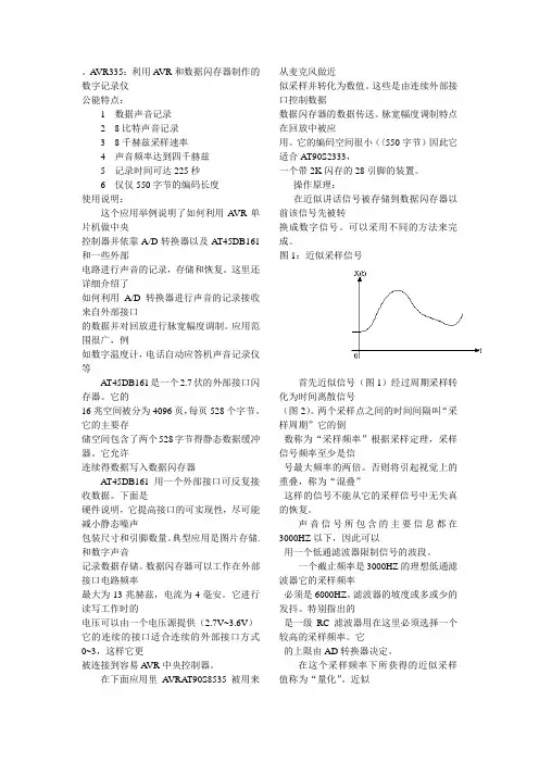
图1:近似采样信号首先近似信号(图1)经过周期采样转化为时间离散信号(图2)。
两个采样点之间的时间间隔叫“采样周期”它的倒数称为“采样频率”根据采样定理,采样信号频率至少是信号最大频率的两倍。
否则将引起视觉上的重叠,称为“混叠”这样的信号不能从它的采样信号中无失真的恢复。

For additional information, onlineregistration, and exclusive specialoffers please visit our website:Model T035Color ChangingAlarm ClockIntroductionThank you for selecting this Timex Model T035 Color Changing Alarm Clock with Soothing Sounds. This model includes:• A large LCD display with momentary Indiglo® color changing back light.• A programmable Auto-Snooze alarm.• Wake to one of 4 Soothing Sounds or a buzzer alarm.• Sleep to Soothing Sounds with auto-shutoff.• A 24-hour reminder/nap timer.Please take the time to review this manual completely and carefully to insure that you are getting the maximum benefit from all of the unique features included in this Timex product.Once again, thank you for selecting Timex.Table of ContentsControls And Indicators (1)Main Display (2)Installing the Batteries (2)Operating Instructions............................................................................................................................................... 3-6 Limited 90-day Warranty Information. (7)Maintenance• Place the unit on a level surface away from sources of direct sunlight or excessive heat.• Protect your furniture when placing your unit on a natural wood and lacquered finish. A cloth or other protective material should be placed between it and the furniture.• Clean your unit with a soft cloth moistened only with mild soap and water. Stronger cleaning agents, such as Benzene, thinner or similar materials can damage the surface of the unit.Warning: Changes or modifications to this unit not expressly approved by the party responsible for compliance could void the user’s authority to operate the equipment.NOTE: This equipment has been tested and found to comply with the limits for a Class B digital device, pursuant to Part 15 of the FCC Rules. These limits are designed to provide reasonable protection against harmful interference in a residential installation. This equipment generates, uses and can radiate radio frequency energy and , if not installed and used in accordance with the instructions, may cause harmful interference to radio communications. However, there is no guarantee that interference will not occur in a particular installation. If this equipment does cause harmful interference to radio or television reception, which can be determined by turning the equipment off and on, the user is encouraged to try to correct the interference by one or more of the following measures:• Reorient or relocate the receiving antenna.• Increase the separation between the equipment and receiver.• Connect the equipment into an outlet on a circuit different from that to which the receiver is connected.• Consult the dealer or an experienced radio/TV technician for help.This Class B digital apparatus complies with Canadian ICES-003.Cet appareil numérique de la classe B est conforme à la norme NMB-003 du Canada.This device complies with Part 15 of the FCC Rules, operation is subject to thefollowing two conditions: (1) This device may not cause harmful interference, and(2) this device must accept any interference received, including interference thatmay cause undesired operation.For models that require more than one battery• Do not mix with used or other battery types/brands• Replace all batteries at the same time• Do not open batteries• Do not dispose of in fire • Do not heat above 75ºC (167ºF) • Do not expose contents to water • Do not charge or recharge • Do not install backwardsControls and IndicatorsFront PanelTIMER ButtonSOUND Button TIME ButtonSET ButtonMain DisplayCurrent Time IndicatorAlarm Time IndicatorTIMER Indicator Alarm ‘ON’ Indicator Snooze ‘ON’ IndicatorAM/PM IndicatorsTime and Alarm Time DisplayMonth/Date DisplayDay Indicator Indoor Temperature Display Installing the Batteries• P ress down on the battery door locking tab and remove the door.• I nstall 3 fresh alkaline “AAA” batteries in the compartment. Be sure tofollow the polarity (+ / - ) markings engraved in the battery compartment.If the batteries are inserted incorrectly the unit will not work.• Replace the battery door.When the batteries are installed for the first time the clock will 'beep' once and the display will appear as shown below:"Operating InstructionsSetting The Clock To The Correct Time of Daysymbol in the upper left corner of the display indicates that the display is showing the wake-up time. Pressing the MODE button cycles the display between the current time and wake-up time.1.2.adjust the hour. Be sure to set correctly for AM or PM.3. Press the SET button again. The minutes begin to flash. Press the UP or DOWN buttons to adjust the minutes.4. Press the SET button again. The Year begins to flash at 2011. Press the UP button to adjust the year if necessary.5. Press the SET button again. The Month display begins to flash. Press the UP or DOWN buttons to adjust the month (1 =January, 2 = February, etc)6. Press the SET button again. The Date display begins to flash. Press the UP or DOWN buttons to adjust the date. TheDAY indicator changes automatically to match the Year, Month, and Date display.When you are finished with the above settings you can press the SET button again to exit the setting mode and start the clock running. Or, after 60 seconds the clock automatically exits the setting mode and begins to run. Note: The flashing colon between the hour and minute digits acts as a seconds counter.Indoor Temperature DisplayThis clock includes a built in temperature sensor and indoor temperature display. The indoor temperature can be displayed in Centigrade (C°) or Fahrenheit (F°). The initial default setting when the batteries are installed is Centigrade. To switch the display between Centigrade and Fahrenheit press the DOWN button. Note: If you place this clock on a windowsill or similar location where it may be exposed to direct sunlight or cold winter temperatures you will not get an accurate room temperature reading.12/24-Hour Time DisplayThis clock can display the time in 12-hour format with AM/PM indicators, or in 24-hour format, often referred to as ‘military time’. To switch the display between 12 and 24-hour time formats, press the UP button.Momentary Lighting SystemEach time you press any front panel button to make adjustment the lighting will turn on for approximately 5 seconds and the shut off automatically to extend the battery life.Setting the Wake-up Time, Auto Snooze Time, and Wake-up SoundThis clock features a programmable Snooze/ Repeat Alarm that you may turn ‘On’ or ‘Off’. If the Snooze function is turned‘On’ the alarm will automatically enter the Snooze mode and shut ‘Off’ after two minutes, and then turn ‘On’ again one minute later. You may adjust the amount of Snooze time between one minute and 60 minutes. The initial default setting is one minute.You may also choose which of the 4 soothing sounds or the electronic buzzer alarm you want to turn on at the wake-up time.1. Press the MODE button to change the display from current time mode to wake-up time mode. The bell symbolappears in the display. The initial alarm setting is 12:00 AM.2. Press the SET button. The wake-up hour digits begin to flash. Press the UP or DOWN buttons to adjust the wake-uphour. Be sure to set correctly for AM or PM.3. Press the SET button again. The wake-up minutes begin to flash. Press the UP or DOWN to adjust the wake up minutes.4. Press the SET button again. The Snooze Indicator and Snooze time display (01) begin to flash. Press the UP or DOWNbutton to select the desired amount of Snooze time. For example, if you select 5 minutes of Snooze time, the alarm will automatically turn on again in 5 minutes.5. Press the SET button again. The number ”1” begins flashing in the Time display. Press the UP or DOWN buttons to hearand select from among the 4 soothing sounds or the electronic buzzer as your wake-up alarm sound.6. Press the SET button once more and the clock will return to the wake-up time mode, then press the MODE button tochange to current time mode, or if you do not press any button for 1 minute the clock will return to the current time display automatically.Activating the Alarm and the Auto Snooze TimeAfter you have set the desired wake-up time, Snooze time, and wake-up sound as described in Steps 1 through 6 above you must still activate the alarm and snooze functions as follows:1. If the display is showing current time press the MODE button to change the display to your desired wake-up time.2. While the wake-up time is showing on the display press the DOWN button once to activate the alarm. The alarm indicatorappears in the display to confirm that the alarm is activated.3. While the wake-up time is showing on the display press the DOWN button once more to activate the snooze function.The snooze indicator appears in the display to confirm that the snooze function is activated.4. To deactivate the alarm and the auto-snooze functions press the DOWN button once more. Both the alarm indicatorsand the snooze indicators disappear from the display.At the selected wake-up time if only the alarm is activated the alarm will turn on to the selected soothing sound or buzzer alarm. The alarm sound starts softly and gradually increases in volume. The alarm will continue for 2 minutes and then shutoff and reset itself for the following day. To stop the alarm sooner press any of the front panel buttons except the SOUND button.At the selected wake-up time if both the alarm and the auto-snooze functions are activated the alarm will turn on for 2 minutes and then enter the auto snooze mode. The alarm will turn off for the number of snooze minutes that you selected above and then turn on again for 2 minutes. During snooze operation the snooze indicator flashes in the display. The alarm/snooze cycle can be repeated a total of 3 times, but after the third time the alarm resets for the following day and the snooze indicator stops flashing. When the alarm turns on you may press any button on the front panel (except the SET button) to stop the alarm sooner and begin the auto snooze cycle immediately. The alarm will turn on again in 2 minutes.If both the alarm indicator and the snooze indicators appear in the display the alarm will turn on for 2 minutes and then the alarm will reset for the same time the following day.Sleep to Soothing Sounds with Auto-ShutoffYou may program the soothing sounds to play for up to 60 minutes and then shut off automatically.1. Press the TIME button. The display will show “0:10” which is the initial default Sleep Timer setting. Continue to press theTIME button to increase the Sleep Timer setting as follows: 0:10 -> 0:20 -> 0:30 -> 0:40 -> 0:50 -> 1:00 -> 0:10 -> etc. 2. When the display is showing the desired amount of Sleep Time Press the SOUND button to begin playback of thesoothing sound. To change to a different soothing sound press the SOUND button once to stop playing the current sound and press again to begin playing the next sound. Repeat this process until you hear the desired sound. The number of the selected sound will appear in place of the Date indicator.3. Press the UP or DOWN button to adjust the volume level of the soothing sound.4. The display will begin counting down from the time you selected. The remaining minutes and seconds will appear in thedisplay. As the soothing sounds are playing the color of the display and inside the cabinet will change every 5 seconds.To pause the soothing sounds press the SOUND button once. To resume playback of the soothing sound Press the SOUND button again.5. When the display counts down to “0:00” the soothing sounds shut off automatically. To shut off the soothing soundbefore the display counts down to 0:00, press the MODE button. The soothing sound stops and the display returns to current time.Countdown / Reminder / Nap TimerThis clock includes a countdown timer that can be used to remind you of an appointment, meeting, or any other event, or when taking a nap, without disturbing your normal wake-up alarm setting. The countdown timer can be set for up to 24 hours in advance. When the timer counts down to “00” the alarm turns on for one minute.To program the countdown timer:1. Press the TIMER button. The display will show 23 Hours, 59 Minutes, and 59 Seconds which is the initial default settingfor the timer. The TIMER indicator also appears.2. Press the SET button. The Hour display begins to flash. Press the UP or DOWN buttons to set the number of hoursbefore the alarm turns ‘On’.3. Press the SET button again. The Minute display begins to flash. Press the UP or DOWN buttons to set the number ofminutes before the alarm turns ‘On’.4. Press the SET button again. The Seconds display begins to flash. Press the UP or DOWN buttons to set the number ofseconds before the alarm turns ‘On’.5. When the display is showing the desired Hours, Minutes, and Seconds, press the TIMER button once to enter the newtimer setting in the memory, and once more to start the countdown timer. The display will begin counting down. Note: If you want to pause the countdown at any time press the TIMER button again. Press the TIMER button once more to resume the countdown.6. When the countdown has started you can press the MODE button to change the display back to the current time, orafter 60 seconds the display will change back to the current time automatically. To review the amount of countdown time remaining, press the TIMER button at any time, and then press the MODE button to return to current time.7. When the timer counts down to “00” the alarm will turn on and continue for one minute. To stop the alarm sooner, pressany button on the front panel.NOTES:• When you change the timer from the 23:59:59 default setting to a new setting, the new setting becomes the new default.For example, if you program the alarm to turn on after 90 minutes, this becomes the new default setting. The next time you press the TIMER button the new default setting on the display will be 90 minutes.• When the timer begins counting down the display and cabinet lighting will remain ‘On’ for 5 seconds and then shut off automatically to extend the battery life.Replacing the BatteriesWhen the display becomes dim and begins to fade and the volume of the sounds becomes weak you should replace the batteries as soon as possible. If weak or exhausted batteries are left in the battery compartment they will eventually leak and cause damage to the unit and possible damage to the surface below the unit as well.Always replace all 3 batteries at the same time and do not mix different types of batteries.IMPORTANT: Make sure you have the 3 new batteries removed from their package and ready to install before you remove the old batteries from the unit. If you can replace the batteries within one minute you will not need to reset the clock. But if there are no batteries in the battery compartment for more than one minute it will be necessary to reset all clock functions after the new batteries are installed.Limited 90-Day Warranty InformationTimex Audio Products, a division of SDI Technologies Inc. (hereafter referred to as SDI Technologies), warrants this product to be free from defects in workmanship and materials, under normal use and conditions, for a period of 90 days from the date of original purchase.Should service be required by reason of any defect or malfunction during the warranty period, SDI Technologies will repair or, at its discretion, replace this product without charge (except for a $2.00 charge for handling, packing, return UPS/postage, and insurance). This decision is subject to verification of the defect or malfunction upon delivery of this product to the Factory Service Center listed below. The product must include proof of purchase, including date of purchase. The fee for service after the warranty period or without proof of purchase is $4.00.Before returning this product for service, please first replace the batteries (if applicable) with fresh ones, as exhausted or defective batteries are the most common cause of problems encountered.If service is still required:1. Remove batteries (if applicable) and pack the unit in a well-padded, heavy corrugated box.2. Enclose a photocopy of your sales receipt, credit card statement, or other proof of the date of purchase.3. Enclose a check or money order payable to the order of SDI Technologies, Inc. for the sum of $2.00 (or $4.00 if after thewarranty period or without proof of purchase).4. Send the unit prepaid to the Factory Service Center listed below:Consumer Repair DepartmentSDI Technologies Inc.Timex Audio Products Division1330 Goodyear DriveEl Paso TX 79936-6420NOTE: This warranty is valid only if the product is used for the purpose for which it was designed. It does not cover (i) products which have been damaged by negligence, misuse or accident, or which have been modified or repaired by unauthorized persons; (ii) cracked or broken cabinets, or units damaged by excessive heat; (iii) damage to tape cassettes (if applicable); (iv) the cost of shipping this product to the Factory Service Center and its return to the owner.This warranty is valid only in the United States of America and does not extend to owners of the product subsequent to the original purchaser. Any applicable implied warranties are also limited to 90 days, and SDI Technologies will not be liable for consequential damages. (Some states do not allow limitations on implied warranties or exclusion of consequential damages, so these restrictions may not apply to you.) This warranty gives you specific legal rights, and you may also have other rights which vary from state to state.© 2011 SDI Technologies, Inc. All rights reservedTIMEX is a registered trademark of Timex Corporation the United States and other countriesT035-061611-A Printed in China。


|V01|The Bluetooth ® word mark and logos are registered trademarks owned by Bluetooth SIG, Inc. and any use of such marks by D&M Holdings Inc. is under license. Dolby, Dolby Atmos, and the double-D symbol are trademarks of Dolby Laboratories. • DTS, the Symbol, DTS in combination with the Symbol, DTS:X, and the DTS:X logo are registered trademarks or trademarks of DTS, Inc. in the United States and/or other countries. • The Spotify software is subject to third party licenses found here: /connect/third-party-licenses • Other trademarks and trade names are those of their respective owners.Denon is a trademark or registered trademark of D&M Holdings, Inc.* All specs can be subject to changeHigh-Performance Discrete 5-Channel AmplifierFeaturing discrete power output devices on all channels, the AVR-S540BT delivers a maximum of 140 watts per channel. It’s equipped with low impedance drive capability for operational stability within a wide range of speakers.Advanced HDMI Video SectionThe advanced HDMI video section of the AVR-S540BT lets you enjoy your favorite movies and shows with the best picture quality available. All five HDMI inputs support 4:4:4 Pure Color sub-sampling, HDR, BT.2020 pass-through, Dolby Vision compatibility and HLG (Hybrid Log-Gamma); full 4K Ultra HD with 60Hz pass-through and HDCP 2.2 processing is available on three HDMI ports to support copy-protected content.Easy Setup ExperienceThe included AVR-S540BT Quick Start Guide provides simple, clear instructions for how to get started. Once you connect your TV to the AVR-S540BT via HDMI, the exclusive Denon Setup Assistant appears on your TV screen to walk you through setup, step by step. A row of color-coded speaker connections is laid out horizontally, making organizing and connecting speaker wires simple.Bluetooth Built-inYour favorite tracks, at your fingertips. Stream music from your computer or smart devices with the AVR-S540BT and built-inBluetooth. It can remember up to eight paired Bluetooth devices, so invite family and friends to share their music and enjoy the audio quality of the AVR-S540BT. To stream via Bluetooth, simply select the Denon AVR-S540BT from the Bluetooth menu on your smart device.Quick Selects for User-Friendly Audio TuningThe Denon AVR-S540BT front panel features four Quick Select buttons that store your preferred audio settings for each source. Switch between television, Blu-Ray, pre-amplifiers and more, and the AVR-S540BT adjusts the EQ settings to your preferences for that media source. Use the buttons on the front panel or opt for the same Quick Selects on the AVR remote for faster control.Front USB Port for High-Resolution AudioIn addition to numerous analog and digital AV connectors, the AVR-S540BT features a USB port on the front panel for convenient audio playback. It’s compatible with a wide range of portable USB devices and supports MP3, WMA, FLAC and MPEG-4/AAC tracks. Whether you want to listen to your latest MP3 download or soak in the fidelity of audiophile-quality FLAC recordings, you have quick access to your favorite songs.Denon 500 Series Remote AppBetter control in your back pocket. The Denon 500 Series Remote app for iOS and Android makes using the AVR-S540BT even easier —adjust volume, turn it on or off, mute the music, and select a source. Download the Denon 500 Series Remote app patible with Denon HEOS LinkControl the Denon AVR-S540BT with your Smart TV remote via the HDMI CEC functionality associated with your Smart TV. Simply set “HDMI Control” to ON in your receiver, then set “Smart Menu” to ON and begin controlling the AVR-S540BT with your TV remote. The Smart Menu home screen provides you quick access to source and surround mode selections, the AVR’s setup menu and four Smart Selects.100+ Years of Firsts in Audio TechnologyFounded in 1910, Denon has a deep heritage of “firsts” in audio technology — from Japan’s first audio electronics manufacturer, to producing the world’s first commercial CDs. This focusedinvestment in audio R&D ensures you get the latest technology and highest quality with every listening experience.Denon 1 Viper Way Vista, CA 。
AVRISP MKII编程器使用说明谢谢您使用A VRISPMKII下载器如有问题,可与我处技术支持部门联系A VR单片机开发工具网友情赞助,提供测试所需的各种开发平台,再这里向A VR单片机学习网的朋友致以诚挚的谢意。
网址:/总体介绍产品简介A VRISP MKII 下载器是ATMEL 公司开发的A VRISP 第二代产品,USB接口。
A VRISP MKII 支持全系列A VR + 部分其他芯片(如S51等)。
USB接口,便于使用与携带,特别适用于没有串口的台式电脑和笔记本电脑。
A VRISP MKII是一种结构紧密而且容易使用的在线编程工具,它为ATMEL 系列A VR 单片机开发应用程序设计。
由于其尺寸小,它也成为一种为现有的利用A VR单片机的应用程序局升级的极好的工具。
A VRISP MKII是由USB供电,因而A VR ISP 编程器无需额外能源供应。
A VRISP MKII编程接口是集成于A VR Studio中的。
Flash,EEPROM和所有的Fuse和Lock bit可编程ISP选项,可以选择单个分别编程或者连续自动编程。
我公司生产的A VRISP MKII在线编程器和atmel官方的A VRISP MKII在线编程器功能上完全兼容,但价格更低,是工厂,学校,个人等开发A VR单片机的首选工具。
产品特点A VR Studio4.1x 接口支持所有A VR芯片的ISP编程可以对Flash和EEPROM进行编程支持熔丝位和锁定位的编程支持RC振荡器校准可以工作在2.7伏到5.5伏电压之间速度可调,支持50Hz~4MHz的isp时钟频率使用USB高达4MHz的全速通讯,兼容USB2.0可直接利用USB供电而不需要额外供电A VR Studio完全支持A VRISPMKII,我们推荐使用最新的A VR Studio 4.X。
支持芯片型号AT90PWM1、AT90PWM2、AT90PWM216、AT90PWM2B、AT90PWM3、AT90PWM316、AT90PWM3B。
xx故障诊断代码1 维修呼叫程序呼叫流程……………………………………………………………………………… 2-13002-xxx HDD002-770 作业模板处理-HD 满RAP……………………………………………… 2-15003-xxx IPS-ESS 通讯003-318 IIT 软件故障RAP ……………………………………………………… 2-17003-319 IIT 视频驱动程序检测故障RAP ……………………………………… 2-17003-320 IISS-ESS 通讯故障1 RAP …………………………………………… 2-18003-321 IISS-ESS 通讯故障2 RAP …………………………………………… 2-18003-322 IISS-ESS 通讯故障3 RAP …………………………………………… 2-19003-323 IISS-ESS 通讯故障4 RAP …………………………………………… 2-19003-324 IISS-ESS 通讯故障5 RAP …………………………………………… 2-20003-325 IISS-ESS 通讯故障6 RAP …………………………………………… 2-20003-326 IISS-ESS 通讯故障7 RAP …………………………………………… 2-21003-327 IISS-ESS 通讯故障8 RAP …………………………………………… 2-21003-328 IISS-ESS 通讯故障9 RAP …………………………………………… 2-22003-329 IISS-ESS 通讯故障10 RAP ………………………………………… 2-003-330 IISS-ESS 通讯故障11 RAP ………………………………………… 2-23003-331 IISS-ESS 通讯故障12 RAP ………………………………………… 2-23003-332 IISS-ESS 通讯故障13 RAP ………………………………………… 2-24003-333 IISS-ESS 通讯故障14 RAP ………………………………………… 2-24003-334 IISS-ESS 通讯故障15 RAP ………………………………………… 2-25003-335 IISS-ESS 通讯故障16 RAP ………………………………………… 2-25003-336 IISS-ESS 通讯故障17 RAP ………………………………………… 2-26003-337 IISS-ESS 通讯故障18 RAP ………………………………………… 2-26003-338 IISS-ESS 通讯故障19 RAP ………………………………………… 2-27003-339 IISS-ESS 通讯故障20 RAP ………………………………………… 2-27003-340 IISS-ESS 通讯故障21 RAP ………………………………………… 2-28003-341 IISS-ESS 通讯故障22 RAP ………………………………………… 2-28003-342 IISS-ESS 通讯故障23 RAP ………………………………………… 2-29003-343 IISS-ESS 通讯故障24 RAP ………………………………………… 2-29003-345 X PIO 未锁定故障1 RAP ………………………………………………003-346 X PIO 未锁定故障2 RAP ………………………………………………2-30003-750 书本双面-原稿不够RAP ………………………………………………2-31003-751 PANTHER 容量低下(扫描)RAP …………………………………… 2-31003-753 扫描不能超过300dpi RAP ……………………………………………2-32003-760 扫描设置故障RAP………………………………………………………2-32003-761 不正确的纸盘尺寸RAP…………………………………………………2-33003-763 未发现调整表RAP………………………………………………………2-33003-780 扫描图像压缩故障RAP…………………………………………………2-34003-795 AMS 限制错误RAP …………………………………………………… 2-34003-942 原稿尺寸自动检测故障RAP…………………………………………… 2-35003-944 图像重复计数RAP………………………………………………………2-35003-945 放大倍率不适合RAP……………………………………………………2-36003-946 每个方向都矛盾(复印APS)RAP…………………………………… 2-36003-947 返回原稿计数错误RAP…………………………………………………2-37003-948 返回原稿不匹配RAP……………………………………………………003-949 原稿不适当(图像覆盖)RAP………………………………………… 2-38003-950 混合原稿尺寸错误RAP…………………………………………………2-38003-955 原稿尺寸交换错误RAP…………………………………………………2-39003-956 原稿尺寸不明错误RAP…………………………………………………2-39003-957 原稿尺寸错误RAP………………………………………………………2-40003-963 无APS 目标纸盘RAP …………………………………………………2-40003-965 ATS/APS 无纸(IIT 检测)RAP ……………………………………… 2-41003-966 ATS/APS 无目标(IIT)RAP …………………………………………2-41003-970 传真行存储器溢出RAP…………………………………………………2-42003-972 最大存储页溢出RAP……………………………………………………2-42003-973 各个方向都矛盾…………………………………………………………2-43003-974 下一原稿规格RAP ………………………………………………………2-43003-976 传真行存储器溢出(N up)RAP ……………………………………… 2-44003-977 原稿不匹配(多重扫描)RAP ………………………………………… 2-44003-980 装钉位置错误RAP ………………………………………………………003-981 装钉尺寸错误RAP ………………………………………………………2-45005-xxx DADF005-121 CVT 输送传感器On 卡纸RAP………………………………………… 2-47005-122 CVT 单面/面1 预定位On 卡纸RAP ………………………………… 2-48005-123 CVT 单面/面1 定位卡纸RAP ………………………………………… 2-49005-125 CVT 定位传感器Off 卡纸RAP………………………………………… 2-50005-131 CVT 翻转On 卡纸RAP…………………………………………………2-51005-132 CVT 翻转On 卡纸2RAP ………………………………………………2-52005-134 CVT 翻转传感器Off 卡纸(翻转器)RAP …………………………… 2-53005-135 CVT 面2 预定位On 卡纸RAP…………………………………………2-54005-136 CVT 面2 定位On 卡纸RAP…………………………………………… 2-55005-139 CVT 翻转传感器Off 卡纸RAP………………………………………… 2-56005-145 CVT 定位传感器Off 卡纸(翻转器)RAP …………………………… 2-57005-146 CVT 预定位传感器Off 卡纸RAP……………………………………… 2-58005-147 CVT 预定位传感器Off 卡纸(翻转器)RAP ………………………… 2-59005-194 在FF 混合尺寸xxSS 尺寸不匹配卡纸RAP ………………………… 2-60005-196 CVT 尺寸不匹配卡纸(无混合)RAP………………………………… 2-61005-197 禁止组合尺寸卡纸RAP…………………………………………………2-62005-198 太短尺寸卡纸RAP………………………………………………………2-63005-199 太长尺寸卡纸RAP………………………………………………………2-64005-280 DADF EEPROM 故障RAP …………………………………………… 2-65005-283 DADF 高度传感器逻辑故障RAP……………………………………… 2-65005-284 DADF APS 传感器故障RAP …………………………………………2-66005-285 DADF 轻推辊提升故障RAP……………………………………………2-67005-286 DADF 输出传感器故障RAP……………………………………………2-68005-302 DADF 输送器盖联锁打开RAP………………………………………… 2-69005-304 CVT 稿台联锁打开RAP ………………………………………………2-70005-305 CVT 输送器联锁打开(运行)RAP…………………………………… 2-70005-307 CVT 稿台联锁在运行xx打开RA ……………………………………… 2-71005-906 CVT 输送传感器静态卡纸RAP ……………………………………… 2-71005-907 CVT 预定位传感器静态卡纸RAP……………………………………… 2-72005-908 CVT 定位传感器静态卡纸RAP………………………………………… 2-72005-913 CVT 翻转传感器静态卡纸RAP………………………………………… 2-73005-915 CVT APS No1 传感器静态卡纸RAP ………………………………… 2-73005-916 CVT APS No2 传感器静态卡纸RAP ………………………………… 2-74005-917 CVT APS No3 传感器静态卡纸RAP ………………………………… 2-74005-942 DADF xx放置的原稿故障RAP ………………………………………… 2-75005-943 DADF 盘提升故障RAP …………………………………………………2-76010-xxx 定影器2nd Version 09/2004 状态-指示-维修DC236/286 2-1010-313 控制热敏电阻故障RAP…………………………………………………2-77010-314 侧端热敏电阻故障RAP…………………………………………………2-77010-318 热-下跌恢复故障RAP …………………………………………………2-78010-320 热辊过热故障RAP………………………………………………………2-78010-327 定影器On 时间故障RAP……………………………………………… 2-79010-398 定影器锁位故障RAP……………………………………………………2-80012-xxx 装订器012-111 装订器H-传输xx传感器Off 卡纸RAP……………………………… 2-81012-112 装订器H-传输xx传感器On 卡纸RAP……………………………… 2-82012-121 H-传输出口传感器Off 卡纸RA P ……………………………………… 2-83012-126 H-传输xx传感器Off 卡纸RAP ……………………………………… 2-84012-151 编辑盘xx传感器Off 卡纸RAP ……………………………………… 2-85012-152 编辑盘xx传感器On 卡纸RAP ……………………………………… 2-86012-161 装订器压板卡纸RAP……………………………………………………2-87012-162 H-传输出口传感器On 卡纸RAP……………………………………… 2-88012-211 堆积盘故障RAP………………………………………………………… 2-89012-212 堆积盘上限故障RAP……………………………………………………2-90012-221 前对齐板原位传感器On 故障RAP…………………………………… 2-91012-223 前对齐板原位传感器Off 故障RAP…………………………………… 2-92012-224 后对齐板原位传感器Off 故障RAP…………………………………… 2-93012-260 排出压板原位传感器On 故障RAP…………………………………… 2-94012-263 后对齐板故障RAP………………………………………………………2-95012-282 排出压板原位传感器Off 故障RAP ………………………………… 2-96012-283 放置压板原位传感器On 故障RAP ………………………………… 2-97012-284 放置压板原位传感器Off 故障RAP ………………………………… 2-98012-291 装订器故障RAP …………………………………………………… 2-99 012-293 装订前角传感器On 故障RAP ………………………………………… 2-100012-294 装订前角传感器Off 故障RAP ………………………………………… 2-101012-295 装订移动传感器On 故障RAP ………………………………………… 2-102012-296 装订移动传感器Off 故障RAP ………………………………………… 2-103012-301 装订器顶盖打开RAP ……………………………………………………2-104012-302 装订器前盖打开RAP ……………………………………………………2-104012-303 装订器H-传输盖打开RAP ……………………………………………2-105012-901 装订器H-传输xx传感器静态卡纸RAP……………………………… 2-105012-902 H-传输出口传感器静态卡纸RAP……………………………………… 2-106012-903 纸张留在编辑盘xx传感器RAP……………………………………… 2-106012-905 编辑盘纸张传感器静态卡纸RAP……………………………………… 2-107012-923 H-传输xx传感器静态卡纸BRAP…………………………………… 2-107016-xxx 传真服务016-210 SW 选项故障(HDD 不存在)RAP…………………………………… 2-109016-211 SW 选项故障(系统存储器不足)RAP ……………………………… 2-109016-212 SW 选项故障(页存储器不足)RAP ………………………………… 2-110016-213 SW 选项故障(打印机卡不存在)RAP ……………………………… 2-110016-214 SW 选项故障(传真卡不存在)RAP ………………………………… 2-111016-215 SW 选项故障(JPEG 板不存在)RAP ……………………………… 2-111016-311 扫描器未安装RAP………………………………………………………2-112016-315 IIT 接口故障RAP ……………………………………………………… 2-112016-316 未检测到页存储器RAP…………………………………………………2-113016-317 页存储器xx止-标准RAP ………………………………………………2-113016-318 页存储器xx止-选项RAP ………………………………………………2-114016-321 传真模块故障RAP …………………………………………………… 2-114016-322 JBA 帐户满RAP………………………………………………………… 2-115016-450 SMB 主机名重复RAP …………………………………………………2-115016-454 DNS 动态更新故障RAP ………………………………………………2-116016-455 SNTP 服务器超时RAP …………………………………………………2-116016-456 SNTP 时间异步RAP ……………………………………………………2-117016-503 SMTP 服务器重定向故障RAP………………………………………… 2-117016-504 POP 服务器重定向故障RAP …………………………………………2-118016-505 POP 重定向验证故障RAP ……………………………………………2-118016-600 KO 验证锁定RAP ……………………………………………………… 2-119016-601 非法访问检测RAP………………………………………………………2-119016-701 ART EX 内存不足RAP…………………………………………………2-120016-702 页缓冲器不足RAP………………………………………………………2-120016-703 E-mail 至无效邮箱RAP…………………………………………………2-121016-704 邮箱满RAP……………………………………………………………… 2-121016-705 安全打印故障RAP………………………………………………………2-122016-706 最大用户数超出RAP……………………………………………………2-1222-123016-708 HD 因注解/水印图象而满RAP………………………………………… 2-123016-709 ART EX 命令故障RAP………………………………………………… 2-124016-710 xx打印故障RAP……………………………………………………… 2-124016-711 E-mail 传输尺寸限制超出RAP………………………………………… 2-125016-712 PANTHER 能下低下(I-Formatted)RAP…………………………… 2-125016-716 TIFF 数据溢出RAP …………………………………………………… 2-126016-718 超出PCL6 存储器RAP…………………………………………………2-126016-719 超出PCL 存储器RAP …………………………………………………2-127016-720 PCL 命令故障RAP……………………………………………………… 2-127016-721 其它错误RAP…………………………………………………………… 2-128016-722 作业被装订位置NG 删除RAP………………………………………… 2-128016-728 不支持TIFF 数据RAP …………………………………………………2-129016-729 TIFF 数据尺寸xxRAP ……………………………………………… 2-129016-730 不支持ART 命令RAP …………………………………………………2-1302-130016-732 表格未注册RAP………………………………………………………… 2-131016-735 更新作业模板RAP………………………………………………………2-131016-736 远程目录加锁错误………………………………………………………2-132016-737 远程加锁目录卸载错误………………………………………………… 2-132016-746 不支持PDF 文件RAP …………………………………………………2-133016-748 HD 满RAP ……………………………………………………………… 2-133016-749 JCL 语法错误RAP……………………………………………………… 2-134016-751 PDF 故障RAP ………………………………………………………… 2-134016-752 PDF 内存不足RAP………………………………………………………2-135016-753 PDF 命令不匹配RAP……………………………………………………2-135016-754 PDF LZW 未安装RAP ………………………………………………… 2-136016-755 PDF 打印被禁止RAP ………………………………………………… 2-136016-756 审计-禁止服务RAP ……………………………………………………2-137016-757 审计-无效用户RAP ……………………………………………………2-137016-758 审计-禁止功能RAP ……………………………………………………2-138016-759 审计-达到限制RAP ……………………………………………………2-138016-760 PS 解压缩故障RAP …………………………………………………… 2-139016-761 FIFO 空RAP …………………………………………………………… 2-139016-762 打印语言未安装RAP……………………………………………………2 - 1 4 0状态-指示-维修09/2004 2nd Version2-2 DC236/286016-764 SMTP 服务器连接故障RAP……………………………………………2 - 1 4 0016-765 SMTP 服务器HDD 满RAP ……………………………………………___________2 - 1 4 1016-766 SMTP 服务器文件系统RAP……………………………………………2 - 1 4 1016-767 无效的E-mail 地址RAP ………………………………………………2 - 1 4 2016-768 无效的发送者地址………………………………………………………2 - 1 4 2016-769 SMTP 服务器不支持DNS R AP ………………………………………2 - 1 4 3016-771 扫描数据贮藏室(DNS 地址)错误RAP …………………………… 2 - 1 4 4016-772 扫描数据贮藏室(DNS 库)错误RAP ……………………………… 2 - 1 4 4016-773 无效的IP 地址RAP (2)- 1 4 4- 1 4 5016-775 HD 满-图像转换RAP (2)- 1 4 5016-776 图像转换错误RAP (2)- 1 4 6016-777 图像转换错误RAP (2)- 1 4 6016-778 HD 满-扫描图像转换RAP………………………………………………2 - 1 4 7016-779 扫描图像转换错误RAP…………………………………………………2 - 1 4 7016-780 HD 访问错误-图像转换RAP…………………………………………… 2 - 1 4 8016-781 扫描服务器连接错误RAP……………………………………………… 2 - 1 4 8016-782 扫描服务器登录错误RAP……………………………………………… 2 - 1 4 9016-783 无效的服务器路径RAP…………………………………………………2 - 1 4 9016-784 服务器写错误RAP (2)- 1 5 0016-785 服务器HD 满RAP (2)- 1 5 0016-786 HD 满-扫描写入错误RAP………………………………………………2 - 1 5 1016-787 无效的服务器IP 地址RAP …………………………………………… 2 - 1 5 1016-788 检查浏览器故障RAP……………………………………………………2 - 1 5 22 - 1 5 2016-791 文件检索故障RAP (2)- 1 5 3016-792 未发现指定作业RAP……………………………………………………2 - 1 5 3016-793 MF I/O HD 满RAP……………………………………………………… 2 -1 5 4016-798 No Trust Marking 选择RAP……………………………………………2 - 1 5 4016-799 PL W 打印指令故障RAP ………………………………………………2 - 1 5 5016-981 HDD 访问错误RAP (2)- 1 5 5016-982 HDD 访问错误2 RAP (2)- 1 5 6016-985 数据尺寸溢出(扫描到E-mail)RAP………………………………… 2 - 1 5 6021-xxx 传真021-360 EP 附件故障RAP………………………………………………………___________2-15 7021-361 EP 附件各类配置错误RAP……………………………………………2-15 7021-732 EP 附件-服务被禁用RAP ……………………………………………2-15 8021-733 EP 附件-服务受彩色模式限制RAP ………………………………… 2-15 8021-750 用过零件请求处理故障(EP-SV)RAP …………………………… 2-15 9021-751 维护请求故障(EP-SV)RAP…………………………………………2-1 5 9021-770 用过零件请求处理故障(EP-SV)RAP……………………………… 2-1 6 0021-771 维护请求故障(EP-DX)RAP…………………………………………2 - 1 6 0021-772 EP-DX-安装/卸载故障RAP……………………………………………2-16 1021-941 EP-扫描服务因禁用而暂行RAP……………………………………… 2-16 1021-942 EP-扫描服务因彩色模式而暂行RAP………………………………… 2-16 2021-943 EP-打印服务因禁用而暂行RAP……………………………………… 2-16 2021-944 EP-打印服务因彩色模式而暂行RAP………………………………… 2-16 3021-945 EP-服务因禁用而暂行RAP……………………………………………2-16 3021-946 EP-服务因彩色模式而暂行RAP……………………………………… 2-16 4024-xxx IOT-ESS 通讯024-340 IOT-ESS 通讯故障1 RAP………………………………………………2-165024-341 IOT-ESS 通讯故障2 RAP………………………………………………2-165024-342 IOT-ESS 通讯故障3 RAP………………………………………………2-166024-343 IOT-ESS 通讯故障4 RAP………………………………………………2-166024-345 IOT-ESS 通讯故障5 RAP………………………………………………2-1672-167024-347 IOT-ESS 通讯故障7 RAP………………………………………………2-168024-348 IOT-ESS 通讯故障8 RAP………………………………………………2-168024-349 IOT-ESS 通讯故障9 RAP………………………………………………2-169024-350 IOT-ESS 通讯故障10 RAP ……………………………………………2-169024-351 IOT-ESS 通讯故障11 RAP ……………………………………………2-170024-354 IOT-ESS 通讯故障14 RAP ……………………………………………2-170024-356 IOT-ESS 通讯故障16 RAP ……………………………………………2-171024-362 页面同步非法启动RAP………………………………………………… 2-171024-363 页面同步非法停止RAP………………………………………………… 2-172024-364 DMA 传输故障RAP ……………………………………………………2-172024-367 解压缩其他故障RAP……………………………………………………2-173024-368 PCI 错误RAP…………………………………………………………… 2-173024-370 标志码检测故障RAP……………………………………………………2-174024-371 IOT-ESS 通讯故障21 RAP ……………………………………………2-1742-175024-373 IOT-ESS 通讯故障23 RAP ……………………………………………2-175024-375 IOT-ESS 通讯故障23 RAP ……………………………………………2-176024-746 打印请求故障—纸张RAP……………………………………………… 2-176024-747 打印指令故障RAP………………………………………………………2-177024-910 纸盘1 尺寸不匹配RAP………………………………………………… 2-177024-911 纸盘2 尺寸不匹配RAP………………………………………………… 2-178024-912 纸盘3 尺寸不匹配RAP………………………………………………… 2-179024-913 纸盘4 尺寸不匹配RAP………………………………………………… 2-180024-916 混合满堆积盘RAP………………………………………………………2-181024-917 堆积盘装订超出计数RAP……………………………………………… 2-182024-919 面朝上盘关闭RAP………………………………………………………2-183024-946 纸盘1 不在位RAP ……………………………………………………2-183024-947 纸盘2 不在位RAP………………………………………………………2-184024-948 纸盘3 不在位RAP………………………………………………………2-184024-949 纸盘4 不在位RAP………………………………………………………2-185024-950 纸盘1 空RAP ………………………………………………………… 2-185024-951 纸盘2 空RAP…………………………………………………………… 2-186024-952 纸盘3 空RAP…………………………………………………………… 2-186024-953 纸盘4 空RAP…………………………………………………………… 2-187024-954 MSI 空RAP …………………………………………………………… 2-187024-958 MSI 尺寸故障RAP …………………………………………………… 2-188024-959 纸盘1 尺寸不匹配RAP ………………………………………………2-188024-960 纸盘2 尺寸不匹配RAP………………………………………………… 2-189024-961 纸盘3 尺寸不匹配RAP………………………………………………… 2-189024-962 纸盘4 尺寸不匹配RAP………………………………………………… 2-190024-964 装订器张数超出RAP……………………………………………………2-190024-965 ATS/APS 无纸(IOT 检测)RAP ……………………………………2-191024-966 ATS/APS 元目标错误RAP ……………………………………………2-192024-967 不同宽度混合纸张检测(装订器作业)RAP …………………………… 2-1922nd Version 09/2004 状态-指示-维修DC236/286 2-3024-976 装订器装订静态NG RAP ………………………………………………2-193024-977 装订器输送准备故障RAP……………………………………………… 2-193024-979 装订器接近空RAP………………………………………………………2-194024-980 装订器堆积盘满RAP……………………………………………………2-194024-982 堆积盘下安全警告RAP………………………………………………… 2-195024-985 MSI 输送故障RAP………………………………………………………2-196024-986 打印全部确认RAP………………………………………………………2-197025-xxx 诊断HDD025-596 诊断HDD 维护故障RAP ………………………………………………2-199025-597 诊断HDD 初始化故障RAP …………………………………………… 2-199027-xxx MAIL027-452 重复IP 地址RAP ……………………………………………………… 2-201027-500 SMTP 服务器邮件I/O 故障RAP……………………………………… 2-201027-501 POP 服务器邮件I/O 故障RAP………………………………………… 2-202027-502 POP 邮件I/O 验证故障RAP…………………………………………… 2-202027-700 媒体故障RAP…………………………………………………………… 2-203027-701 未找到媒体RAP………………………………………………………… 2-203027-702 媒体数据未找到/不支持RAP ………………………………………… 2-204027-703 媒体读出器故障/未连接RAP ………………………………………… 2-204027-710 因效S/MIME 邮件错误RAP…………………………………………… 2-205027-711 S/MIME 邮件发送者证书未找到RAP ………………………………… 2-205027-712 S/MIME 邮件发送者证书无效RAP …………………………………… 2-206027-713 S/MIME 邮件被改变RAP………………………………………………2-206027-714 S/MIME 邮件发送者假冒RAP………………………………………… 2-207027-715 S/MIME 邮件证书不被支持RAP……………………………………… 2-207027-716 禁止接收没有签名的E-mailRAP……………………………………… 2-208027-720 未找到扩展服务器主机RAP…………………………………………… 2-208027-721 未找到扩展服务器RAP…………………………………………………2-209027-722 扩展服务器时故障RAP ……………………………………………2-209027-723 扩展服务器验证故障RAP……………………………………………… 2-210027-724 扩展服务器访问故障故障RAP………………………………………… 2-210027-725 扩展服务器操作故障RAP……………………………………………… 2-211027-726 扩展服务器未知状态RAP……………………………………………… 2-211027-727 扩展服务器请求无效参数RAP………………………………………… 2-212027-737 模板服务器读取错误RAP……………………………………………… 2-212027-739 无效模板服务器路径RAP……………………………………………… 2-213027-740 模板服务器登录错误RAP……………………………………………… 2-213027-741 模板服务器连接故障RAP……………………………………………… 2-214027-742 HD 文件系统满RAP ……………………………………………………2-214027-743 模板服务器安装错误RAP……………………………………………… 2-215027-744 模板服务器地址错误(CDNS 带)RAP ……………………………… 2-215027-745 模板服务器地址错误(CDNS 地址)RAP …………………………… 2-216027-746 作业模板服务器未准备RAP…………………………………………… 2-216027-750 传真文件不适合RAP……………………………………………………2-217027-751 作业模板分析错误RAP…………………………………………………2-217027-752 要求的用户输入未输入RAP…………………………………………… 2-218027-753 作业流服务请求禁止RAP……………………………………………… 2-218027-796 E-mail 不打印RAP……………………………………………………… 2-219027-797 无效输出目标RAP………………………………………………………2-219033-xxx 传真控制033-363 传真卡复位(重新引导)RAP ……………………………………………2-221033-710 原稿不存在RAP………………………………………………………… 2-221033-711 文档xx存在非法页面RAP……………………………………………… 2-222033-712 系统内存溢出RAP………………………………………………………2-222033-713 未指定链-环RAP ……………………………………………………… 2-223033-714 扫描错误(未指定文档)RAP ………………………………………… 2-223033-715 不能启动作业RAP………………………………………………………2-224033-716 无指定MAILBOX RAP …………………………………………………2-224033-717 不正确口令RAP………………………………………………………… 2-225033-718 邮箱xx无文档RAP………………………………………………………2-225033-719 被删除传真作业不能恢复RAP………………………………………… 2-226033-720 文档创建故障RAP………………………………………………………2-226033-721 页面创建故障RAP………………………………………………………2-227033-724 传真接收存储器溢出RAP……………………………………………… 2-227033-725 HDD 空间不足RAP …………………………………………………… 2-228033-726 不能打印双面RAP………………………………………………………2-228033-727 不能旋转图像RAP………………………………………………………2-229033-728 删除自动打印RAP………………………………………………………2-229033-730 传真服务恢复错误RAP…………………………………………………2-230033-731 指令不一致RAP………………………………………………………… 2-230033-732 打印作业被强制轮询删除RAP………………………………………… 2-231033-733 传真文档号获取错误RAP……………………………………………… 2-231033-734 传真打印悬置RAP………………………………………………………2-232033-735 传真存储器地址分配超时RAP………………………………………… 2-232033-736 IFAX Off Ramp 错误RA P………………………………………………2-233033-737 传真卡作业删除RAP……………………………………………………033-738 JBIG 信息故障RAP…………………………………………………… 2-234033-740 传真直接接收打印删除RAP…………………………………………… 2-234033-741 传真页面读取打开超时RAP…………………………………………… 2-235033-742 传真页面读取关闭超时RAP…………………………………………… 2-235033-743 传真页面写入打开超时RAP…………………………………………… 2-236033-744 传真页面写入关闭超时RAP…………………………………………… 2-236033-745 传真数据写入超时RAP…………………………………………………2-237033-746 传真数据读取超时RAP…………………………………………………2-237033-747 传真服务不能启动RAP…………………………………………………2-238033-748 传真服务非法顺序RAP…………………………………………………2-238033-749 传真卡内存错误RAP……………………………………………………2-239033-750 传真格式错误RAP………………………………………………………2-239033-790 EP-DX 呼叫等待(不重拨计数)RAP …………………………………… 2-240033-791 EP-DX 呼叫等待(重拨计数)RAP ……………………………………… 2-240033-792 EP-DX 呼叫停止RAP ………………………………………………… 2-034-xxx 传真通讯034-211 传真选项槽1 板故障RAP……………………………………………… 2-243034-212 传真选项槽1 板故障RAP……………………………………………… 2-243034-500 不正确拨号数据RAP……………………………………………………2-244034-501 所连通道拨号错误RAP…………………………………………………2-244034-502 传真内部不可缺少参数错误RAP……………………………………… 2-245034-503 传真内部高层服务错误RAP…………………………………………… 2-245034-504 传真储存存储器溢出RAP……………………………………………… 2-246034-505 传真工作存储器溢出RAP……………………………………………… 2-246状态-指示-维修09/2004 2nd Version2-4 DC236/286034-506 不支持远程功能RAP……………………………………………………2-247034-507 口令检查错误RAP………………………………………………………2-247034-508 通过DTMF 删除传输RAP ……………………………………………2-248034-509 DTMF 非法程序错误RAP………………………………………………2-248034-510 DTMF 程序错误RAP……………………………………………………2-249034-511 远程机器不能发送文件RAP…………………………………………… 2-249034-512 检测到无尽循环RAP……………………………………………………2-250034-513 接收命令错误RAP………………………………………………………2-250034-514 请求的功能不支持RAP…………………………………………………2-251034-515 非法命令被接收RAP……………………………………………………2-251034-519 接收数量超出RAP………………………………………………………2-252034-520 服务数量超出RAP………………………………………………………2-252034-521 内部I/F 错误RAP ………………………………………………………2-253034-522 无手动发送线路RAP……………………………………………………2-253034-523 传真服务被禁止RAP……………………………………………………2-254034-524 不能删除操作RAP………………………………………………………2-254034-525 指定的链-环不存在RAP ………………………………………………2-255034-526 不正确的链-环值RAP …………………………………………………2-255034-527 拨号控制错误RAP………………………………………………………2-256034-528 不能执行手动发送RAP…………………………………………………2-256034-529 无打印的纸张尺寸RAP…………………………………………………2-257034-530 DTMF I/F 超时RAP …………………………………………………… 2-257034-700 G3 节Dicep 超时RAP …………………………………………………2-258034-701 软件复位RAP…………………………………………………………… 2-258034-702 无指定目标RAP………………………………………………………… 2-259034-703 D 信道与网络连接切断RAP…………………………………………… 2-259034-704 ISDN D 信道数据连接错误RAP ……………………………………… 2-260034-705 ISDN 层1 停止-电源ON ………………………………………………2-260034-706 ISDN 层1 停止-电源OFF………………………………………………2-261034-707 FRMR 被接收…………………………………………………………… 2-261034-708 非法帧接收N(R)……………………………………………………2-262034-709 非法帧接收……………………………………………………………… 2-262034-710 …………………………………………………………………………… 2-263 034-711 等待连接超时……………………………………………………………2-263034-712 内部错误(xx断)………………………………………………………2-264034-713 超时-传输删除……………………………………………………………2-264034-714 线路断开-超时T305 ……………………………………………………2-265034-715 线路断开-超时3082 ……………………………………………………2-265034-716 连接超时(T313)………………………………………………………2-266034-717 Resume 超时…………………………………………………………… 2-266034-718 正常断开………………………………………………………………… 2-267034-719 无空闲和有效线路………………………………………………………2-267034-720 超时(60s,T330,309,301,310)……………………………………… 2-268 034-721 错误(xx,内容)………………………………………………… 2-268034-722 悬挂超时………………………………………………………………… 2-269034-723 无指定计时器RAP………………………………………………………2-269034-724 非法顺序RAP…………………………………………………………… 2-270034-725 L3 任务内部错误RAP …………………………………………………2-270034-726 HD81501 I/F 缓冲器忙RAP……………………………………………2-271034-727 任务无响应(对1,300Hz 输入呼叫为3 秒)RAP ………………… 2-271034-728 无效的目标RAP………………………………………………………… 2-034-729 线路切断,内部通道PB 发送RAP…………………………………… 2-272034-730 输入和输出呼叫冲突…………………………………………………… 2-273034-731 传真网络切断(设置错误)…………………………………………… 2-273034-732 传真网络因超时而被切断……………………………………………… 2-274034-733 不正确顺序,呼叫状态………………………………………………… 2-274034-734 HI 任务内部错误RAP …………………………………………………2-275034-735 只与ISDN D 信道连接…………………………………………………2-275034-736 来自传真网络的错误通知……………………………………………… 2-276034-737 输入呼叫响应错误RAP…………………………………………………2-276034-738 层1 启动错误……………………………………………………………2-277034-739 层1 不同步………………………………………………………………2-277034-740 帧传输错误……………………………………………………………… 2-278034-741 不能发送帧……………………………………………………………… 2-278034-742 帧发送低速被检测………………………………………………………2-279034-743 不正常发送帧DMA RAP ………………………………………………034-744 不能接受的信道RAP……………………………………………………2-280034-745 呼出信道设置……………………………………………………………2-280034-746 无可使用线路……………………………………………………………2-281034-747 转换设备拥挤……………………………………………………………2-281034-748 指定线路无法使用………………………………………………………2-282034-750 网络错误………………………………………………………………… 2-282034-751 临时网络错误……………………………………………………………2-283034-752 目标终端忙……………………………………………………………… 2-283034-753 目标不应答……………………………………………………………… 2-284034-754 无来自目标的响应………………………………………………………2-284034-755 目标拒绝呼叫……………………………………………………………2-285034-756 目标故障………………………………………………………………… 2-285034-757 其它(正常,半正常)………………………………………………… 2-286034-758 不正确目标传真拨号号码……………………………………………… 2-286034-759 无xx转网络路由…………………………………………………………034-760 无到目标线路……………………………………………………………2-287034-761 不正确格式目标传真号码……………………………………………… 2-288034-762 设备拒绝………………………………………………………………… 2-288034-763 通讯能力不允许…………………………………………………………2-289034-764 通讯能力未被配置………………………………………………………2-289034-765 服务,性能限制带来的错误…………………………………………… 2-290034-766 所选择的通讯不执行…………………………………………………… 2-290034-767 所选模式不执行…………………………………………………………2-291034-768 只有有限数字信息………………………………………………………2-291034-769 服务,性能产生的错误………………………………………………… 2-292034-770 应答状态查询……………………………………………………………2-292034-771 访问信息被放弃…………………………………………………………2-293034-772 工作之间连接错误………………………………………………………2-293034-773 指定拨号号码无效………………………………………………………2-294034-774 指定的线路无效…………………………………………………………034-775 其他(无效信息类)…………………………………………………… 2-295034-776 所需信息不够……………………………………………………………2-295034-777 不明确的信息类型………………………………………………………2-296034-778 不正确信息或类型………………………………………………………2-296034-779 无信息或未定义…………………………………………………………2-297034-780 无效信息………………………………………………………………… 2-297034-781 呼叫状态,信息不匹配………………………………………………… 2-298034-782 因超时而被错误清除…………………………………………………… 2-2982nd Version 09/2004 状态-指示-维修DC236/286 2-5034-783 其它错误(操作等)…………………………………………………… 2-299034-784 目标号码改变……………………………………………………………2-299034-785 不兼容目标……………………………………………………………… 2-300034-786 呼叫识别码不在使用xx ………………………………………………… 2-300034-787 呼叫识别码在使用xx ……………………………………………………2-301034-788 显示其它原因……………………………………………………………034-789 G4 表示层非法事件……………………………………………………2-302034-790 线路1 未被连接RAP……………………………………………………2-302034-791 线路0(分机)未被连接RAP ………………………………………… 2-303034-792 线路2 未被连接RAP……………………………………………………2-303034-793 线路3 未被连接RAP……………………………………………………2-304034-794 线路4 未被连接RAP……………………………………………………2-304034-795 线路5 未被连接RAP……………………………………………………2-305034-796 拨号错误(不正确传真号码2)RAP ………………………………… 2-305034-797 通讯参数错误RAP………………………………………………………2-306034-798 数据参数错误RAP………………………………………………………2-306034-799 自动拨号无拨号数据RAP……………………………………………… 2-307035-xxx 传真网络035-700 Modem 故障RAP ………………………………………………………___________2-309035-701 T1 传输超时RAP ……………………………………………………… 2-309035-702 目标接收被拒绝RAP …………………………………………………2-310035-703 以相位B 发送时接收到DCNRAP …………………………………… 2-310035-704 目标轮询错误RAP………………………………………………………2-311035-705 DCS/NSS 重新发送超限RAP …………………………………………2-311035-706 减速运行错误RAP …………………………………………………… 2-312035-707 错误的口令/接收错误RAP …………………………………………… 2-312035-708 后-信息重发超限RA P …………………………………………………2-313035-709 RTN 接收RAP ………………………………………………………… 2-313035-710 PIN 接收RAP…………………………………………………………… 2-314035-711 DCN 接收在相位D RAP ………………………………………………2-314035-712 3 NSC 后无响应RAP ………………………………………………… 2-315035-713 发送FTT 之后T2 超时RAP…………………………………………… 2-315035-714 NSC/DTC 之后接收到DCN RAP………………………………………2-316035-715 错误口令-轮询错误RAP ………………………………………………2-316035-716 无后信息-T2 超时RAP …………………………………………………2-317035-717 RTN 发送RAP ………………………………………………………… 2-317。
Installation ManualVEHICLE HANDSFREE KITKRY 101 1613ericssonz2Copyright © September 1995, Ericsson Inc.NOTICE!This manual covers Ericsson and General Electric products manufactured and sold by Ericsson Inc.This manual is published by Ericsson Inc., without any warranty.Improvements and changes to this manual necessitated by typographical errors, inaccuracies of current information, or improvements to programs and/or equipment, may be made by Ericsson Inc., at any time and without notice. Such changes will be incorporated into new editions of this manual. No part of this manual may be reproduced or transmitted in any form or by any means,electronic or mechanical, including photocopying and recording, for any purpose, without the express written permission of Ericsson Inc.3GENERALThe VEHICLE HANDSFREE KIT provides for the safe and easy use of the DPE-100 portable radio in a vehicle.The VEHICLE HANDSFREE KIT powers the radio with the vehicle's battery and provides a microphone and speaker for handsfree use.• The kit includes the following • Handsfree cradle • Mounting brackets • Microphone and clip•Antenna interface cable with TNC connector • Cradle power cable •Fuse kitWIRING TO AN EXTERNAL ANTENNA An external antenna (to be purchased separately) greatly improves performance.Take the following steps to install the antenna cable:1.Remove the plastic insert from theantenna connection hole at the top back of the cradle.2.Push the long connector on theantenna cable through the hole.3.Press the connector into the hole untilit snaps into place and close the opening of the back of the cradle with the grommet found on the antenna cable. Press the antenna cable into the retainer at the bottom of the cradle.45MOUNTING THE CRADLEFollow the steps below to attach the cradle to the swivel mount Locate the cradle within easy reach of the driver where it will not obstruct driving.SWIVEL MOUNTPlace the swivel joint into desired position and mark the drilling area using the holes as a template. Be sure to check the drilling area for hidden obstacles before drilling. Drill the marked holes for unlt placement.1.Place the ball joint against the pocketmount. Insert the large screw through the center of the ball joint & pocket6mount and loosely attach with the nut and the back of the pocket mount.2.Place the unit on the drilled holes andmount it with the screws provided.3.Adjust the ball joint to desired positionand tighten the center screw within the ball joint.4.Slide the cradle over the angledguides and push down until the cradleis secureWIRING TO THE VEHICLE'S BATTERY l.Cut a short 6 - 8 inch length of red wire from the power cable.e the short length of red wire toconnect one terminal of the fuse holder to the positive battery terminal (12 V. battery with negative ground only).3.Connect the power cable's red wire tothe other terminal of the fuse holder.4.Connect the power cable's black wireto ground and insert the 3 Amp fuse into its holder.5.Route the cradle power cable andpush it into the cradle's power jack.7MOUNTING THE MICROPHONE 1.Locate the microphone out-of-the-wayabout 8-12 inches from the driver's face and away f rom windows or other sources of noise. Use the visor clip or adhesive strip to mount the microphone. ALWAYS USE THE VISOR CLIP IF POSSIBLE. The bulb on the microphone must be toward the driver and the mike wire rmust lead away from the driver. Route the mike wire away from vehicle parts that could damage insulation or cut the wire.2.Plug the microphone into the blackcylindrical jack at the end of the cradle cord.8INSERTING AND REMOVING THERADIO Before inserting the radio. check to see if the battery is medium, high. or extra high capacity.If the battery is medium, fold out the support before inserting the radio.INSERTING THE RADIO1.Find the small grooves on the sides ofthe radio at the bottom, and align them with the guides in the base of the cradle. Place the radio straight down into the cradle. The antenna should rest over the groove at the top left of the cradle.92.With the base of the radio in place,gently push the top back into thecradle until you feel it snap in.If the battery is high or extra highcapacity, fold in the support.REMOVING THE RADIOGently pull out on the top of the radio until you feel it loosen, then remove thephone.SPECIFICATIONS• INPUT VOLTAGE 11- 16V.DC/l.7A •CHARGING TEMPERATURE RANGE 25°F. to l05°F.TROUBLESHOOTING10This page intentionally left blank11Ericsson Inc.Private Radio SystemsMountain View RoadLynchburg, Virginia 24502AE/LZT 123 1881 R1A 1-800-528-7711 (Outside USA, 804-528-7711)Printed in U.S.A.。
A VR035:A VR单片机高效的C语言译码特色:访问I/O 存储器特定区域访问映射I/O的存储器访问Flash 数据访问EEPROM 数据创造EEPROM 数据文件变量和数据类型的有效使用位域和位屏蔽的使用宏和函数的使用18种方式缩减代码量5种方式缩减RAM需求调试程序的备忘目录(checklist)更新到支持IAR 版本2编译器引序C 已经逐步地成为编写各类微处理器高级语言.它在编写处理器程序中比汇编语言拥有更多优势:缩减开发时间,简化源程序的维护和移植以及代码的模块化.The penalty can be larger code size and as a result of that often reduced speed.(处罚可以扩大编码的大小,及作为速度减少的一种后果)减少这种不便,A VR的设计构造更加协调于由C编译器典型生成的有效编码和可执行指令.IAR systems的这款C编译器先于A VR设计结构和指令设置的规格说明完成之前开发而成.编译器开发团队和A VR开发团队合作研发了一个适用于微处理器的生成高效、高性能代码的C编译器.应用注解描述了如何利用A VR相比其他微处理器的构造设计优势以及相关开发工具来完成更多高效的C代码.Architecture Tuned FOR C代码A VR的32个8位工作寄存器是高效C译码的一个关键所在,每一个工作寄存器都具有传统累加器的功能. A VR可以同时访问Register File(寄存器文件)中任意2个操作数,并将数据送入ALU(算术逻辑单元)进行相关运算,结果存回到Register File.,整个过程只需要1个时钟周期.当数据存储在32个工作寄存器的时候,每个运算指令某些2个8-bits寄存器可以结合成1个16-bits指针来实现数据从数据存储器和程序存储器高效存取(双字节指针能够达到64KB的寻址范围).甚至为达到更大的存储量,这个16-bits存储器指针结合一个8-bits寄存器便达到24-bits指针来寻址8M字节的数据.无需翻页.取址模式A VR 设计构造中有4个存储器指针被用来数据存取以及程序存储. Stack Pointer (堆栈指针) 用来存储函数调用返回之后的返回地址. C编译器分配1个指针作为参数堆栈.剩余2个通用目的指针被C编译器分派完成程序的装载和数据的存储.下面示例说明了指针是如何高效地用来完成C语言中典型的指针操作char *pointer1 = &table[0] ;char *pointer2 = &table[49] ;*pointer1++ = *- -pointer2 ;生成汇编代码如下:LD R16,-Z ; Pre-decrement Z pointer and load dataST X+, R16 ; Store data and post inceement四个指针地址模式和范例如下所示,当中的指针指令都为single-word(单字)指令执行周期为2个时钟.1. 间接寻址: 数组和指针变量寻址*pointer = 0x00 ;2. 带偏移量的间接寻址: 允许通过指向structrue(指令)第一个元素指针加上偏移量来访问结构体内部所有元素而不需要改变指针的值.同样适用于访问软件堆栈中的变量和数组单元.3. 带后加偏移量的间接寻址:为更有效率地访问数组和指针变量,访问结束后添加偏移量(来改变指针指向)*pointer ++ = 0xFF ;4. 带预加偏移量的间接寻址: 为更有效率地访问数组和指针变量,访问开始前添加偏移量*- -pointer = 0xFF ;该指针可同样用于访问Flash Program Memory(闪存程序存储器),除了用指针来间接寻址Flash Program Memory之外,数据存储器也能被直接寻址.下面给出访问整个数据存储器的双字指令.支持16位/32位的变量A VR指令设置中包含了几条特殊指令来处理16位数据.包括立即数与字相加/相减(ADIW,SBIW). 2条指令2个时钟周期完成的两个16位数据的算术运算以及比较.4条指令4个时钟周期则可以实现32位数据的运算和比较.比一些16位的处理器更加有效率.A VR的C语言代码初始化堆栈指针上电复位或是重起复位后,在任何功能被唤起之前堆栈指针必须重新设置.连接器命令文件决定了堆栈指针的位置尺寸.访问I/O存储器单元用C语言可以方便地访问A VR I/O存储器.所有I/O存储器声明在一个通常名为“ioxxxx.h”头文件中,(xxxx是A VR 产品代号).下面的代码例子显示如何访问I/O单元.C代码行下面是生成相应的汇编代码行.#include <io8515.h> /* 包括象征名的头文件*/_C_task void main(void){Char temp ; /* 声名一个局部变量*//* 读写一个I/O口寄存器*/temp = PIND ; /* 读PIND引脚数据到局部变量temp */// IN R16,LOW(16) ; 读I/O存储器TCCR0 = 0x4F ; /*将数值写入一个I/O单元*/// LDI R17,79 ; 载入立即数// OUT LOW(51),R17 ; 写I/O存储器/* 置单独位和清单独位*/PORTB | = {1<<PIND2} ; /* PIND2是PORTB端口引脚0~7中的一位*/// SBI LOW(24),LOW(2) ; I/O置位/* 置位和清屏蔽位*/DDRD | = 0x0C /* 置DDRD位2和位3 */// IN R17,LOW(17) ; 读I/O寄存器// ORI R17,LOW(12) ; R17内容…或‟立即数// OUT LOW(17),R17 ; 写I/O寄存器ACSR &= ~(0x0c) ; /* 清ACSR中位2和位3 */// IN R17,LOW(8) ; 读I/O寄存器// ANDI R17,LOW(243) ; R17内容…与‟立即数// OUT LOW(8),R17 ; 写I/O寄存器/* 测试单独位是否已经置位或是清零了*/if (USR & (1<<TXC) ) /* 检查UART Tx标志是否置位*/{PORTB | = (1<<PB0) ;// SBIC LOW(11),LOW(6) ; test direct on I/O// SBIC LOW(24),LOW(0) ;While( ! (SPSR & (1<<WCOL) ) ) ; 等待WCOL标志位置位// ?0003: SBIS LOW(14),LOW(6) ; test direct on I/O// RJMP ?0003/* 测试I/O寄存器是否等同于一个屏蔽位*/If ( UDR & 0xF3 ) /* 检查UDR 寄存器…与‟ 0xF3后非零为真*/ {}// IN R16,LOW(12) ; 读I/O寄存器// ANDI R16,LOW(243) ; R16内容…与‟立即数// BREQ ?0008 ; 相等跳转到?0008// ?0008:/* 置位和清I/O寄存器位可以用…宏‟声明*/# define SETBIT(ADDRESS,BIT) (ADDRESS |= (1<<BIT) )# define CLEARBIT(ADDRESS,BIT) (ADDRESS &= ~(1<<BIT) )/* …宏‟指令检查I/O单元的单独位*/#define CHECKBIT((ADDRESS,BIT) (ADDRESS & (1<<BIT) )/* 用法示例*/If (CHECHBIT (PORTD,PIND1) ) /* 检查PIND1引脚是否置位*/{CLEARBIT(PORTD,PIND1) ; /* 清PIND1引脚*/}if (! (CHECKBIT(PORTD,PIND1) ) ) /* 检查PIND1引脚是否已经清零*/{SETBIT(PORTD,PIND1); /* 置位PIND1引脚*/}访问存储器映射I/O 一些A VR单片机包含一个外部数据存储器接口.这些接口能被用来访问外部RAM,EEPROM(可擦可编程程序存储器),或者被用来访问存储器映射I/O .下面的示例显示了如何声名、写、读存储器映射I/O#include < io8515.h>#define reg ( *(char) *) 0x8004 /* 声名一个存储器映射I/O 地址*/_C_task void main( void ){char temp ;reg = 0x05 ; /* 写值作为存储器映射I/O地址*/temp = reg ; /* 读存储器映射I/O 地址*/}如果访问连续的存储器映射地址.最有效的访问方式是声名一个常量指针然后添加一个偏移量来完成转移.下面的示例说明了如何按照上述所说来访问存储器映射I/O.每条指令生成的汇编代码以斜体表示./* 定义存储器映射地址*/#define data 0x0003#define address_hige 0x0002#define address_low 0x0001_C_task void main ( void ){/* 存储器映射起始地址*/unsigned char *pointer = (unsigned char *) 0x0800 ;// LDI R30,LOW(0) ;初始化Z指针// LDI R31,8*(pointer + address_low) |= 0x40 ; /* 读出并修改一个地址*/// LDD R18,Z+1 ; 装载变量// ORI R18,LOW(64) ; …或‟立即数后送回R18// STD Z+1,R18 ; 存回*(pointer + address_high) = 0x00 ; /*写入一个地址*/// STD Z+2,R30 ; 存0PORTC = *(pointer + data ) ; /* 读一个地址* /// LDD R16, Z+3 ; 装载变量// OUT LOW(21) ,R16 ; 输出到端口}注意Z指针要在访问存储器之前初始化,同时指令LDD和STD (装载和存储偏移量)被用来访问数据.LDD和STD都是STD都是单字指令,执行周期为2个时钟.指针只装载一次,存储器映射I/O单元能被声明为局部变量,说明这些变量单元能通过硬件修改,即使通过优化代码行为,访问也不会被移除访问EEPROM数据A VR内置EEPROM数据能够在普通操作方式下读写.便于IAR编译器读写EEPROM数据的宏指令包含在“ina90.h”头文件中.下面的宏在正常情况下被定义为读写EEPROM:#define _EEGET(V AR,ADR) /* 从EEPROM的地址ADR中读取数到变量V AR中*/{While ( EECR & 0x02 ) ; /* 检查EEPROM是否可以读写*/EEAR = (ADR) ; /* 写EEPROM地址寄存器*/EECR |= 0x01 ; /* 设置EEPROM读使能*/(V AR) = EEDR ; /* 在下一个时钟周期将EEPROM数据读出送入变量V AR中*/ }# define _EEPUT(ADR,V AL) /* 写V AL变量到EEPROM地址ADR中*/{While(EECR & 0x02) /* 检查EEPROM是否可以读写*/EEAR = (ADR) ; /* 写EEPROM地址寄存器*/EEDR = (V AL) ; /* 写EEPROM数据寄存器*/EECR |= 0x04 ; /* 置位EEMWE 表示写使能*/EECR |= 0x02 ; /* 写入数据*/}(译者注:写EEPROM操作步骤如下,等待EEWE为0,把EEPROM地址写到EEAR,数据写到EEDR,置位EEMWE,在置位EEMWE为‟1”的4个时钟周期内向EEWE写入…1‟表示写完成)预定义…宏‟来完成对EEPROM的读写操作代码如下# include <io8515.h># incude <ina90.h>#define EE_ADDRESS 0x010 /* 定义EEPROM地址常量*/_C_task void main(void){char temp ;_EEGET(temp,EE_ADDRESS) ; /* 读EEPROM中地址为EE_ADDRESS数据*/Temp +=UDR ; /* 将UART数据添加到temp变量中*/_EEPUT (EE_ADDRESS,temp) ; /* 将数据写入到地址为EE_ADDRESS的EEPROM中*/}注意如果中断使能,必须在写EEPROM中关闭中断使能位来确保写操作没有超时.如果程序中包含了访问EEPROM而进入中断响应的程序段,在读EEPROM之前必须先关闭中断使能来避免EEPROM地址寄存器的错误.变量和数据类型A VR是8位微处理器,16位和32位的变量的使用会被限制在必须使用的地方.下面的示例说明了一个循环记数器分别用8位和16位单元变量的代码量unsigned char count8 = 5 ; /* 声明一个变量分配一个数值*/// LDI R16,5 ; 初始化变量do{ }while(--count8) ; 减循环计数器// ?0004: DEC R16 ; 减一// BRNE ?0004 ; 如果不等则跳转到?0004unsigned int count16 = 6 ; /* 声明一个变量分配一个数值*/// LDI R24,LOW(6) ; 初始化低字节// LDI R25,0 ; 初始化高字节do{ }while(--count16) ; 减循环计数器// ?0004: SBIW R24,LWRD(1) ; 字减立即数// BRNE ?0004 ; 如果不等则跳转到?0004变量和代码量8位变量代码量为6个字节,16位的变量代码量为8字节.各种变量的有高效使用一个C源程序可以分成许多执行不同功能模块的函数.函数通过参数来接收数据并(将处理结果做为)返回数据.函数内部的声名变量被称为局部变量(local variable),函数外部的声名变量被称位全局变量(global variable).局部变量需要在函数被调用之前被保存的时候,必须声名为静态局部变量.声明在函数外部的全局变量被分配到静态数据存储器(SRAM)某一单元.静态数据存储器用来保存全局变量而不能做他用.因此造成SRAM单元的浪费.而使用过多的全局变量会使程序代码可读性和修改性降低.局部变量的优越性在于声明的时候才被分配到寄存器中,在函数调用过程中一直保存直到函数调用结束,or until it is not referenced further.全局变量必须从SRAM中装载到工作寄存器后才能被访问.下面示例了2者在代码量以及执行速度上的区别.char global ; /* 全局变量*/_C_task void main(void){char local ; /* 局部变量*/global -= 45 ; /* 全局变量减去45 */// LDS R16,LWRW(global) ; 从SRAM装载全局变量到工作寄存器R16// SUBI R16,LOW(45) ; 减去立即数// STS LWRD(global),R16 ; 数据存回到先前调用的SRAM单元local - = 34 ; /* 局部变量减去45 */// SUBI R16,LOW(34) ;/* 直接在工作寄存器R16中完成减操作*/}注意到LDS和STS双字指令(可直接从SRAM装载)用来访问静态数据存储器中的变量,执行周期都为2函数被调用开始时,一个静态局部变量被载进一个工作寄存器后会在函数调用结束后存入SRAM单元.因此在函数内部访问变量的次数多于一次的情况下,使用静态局部变量会生成比使用全局变量更加高效的代码.为了限制全局变量的使用. C语言普遍采用函数调用时通过参数来传递自变量并且调用完成则返回处理结果的方式.工作寄存器R16~R23中最多有2个参数能够同时成为自变量传递进入函数(参数类型可为字符、整型、长整型、单精度、双精度不限).而多于2个参数或是复杂的数据类型(比如数组和结构体)的情况则可放入软件堆栈或是Passed between functions as pointers to SRAM locations (通过指向SRAM单元的功能)需要采用全局变量的时候,将其合并在合适的造体中.从而使C编译器间接的赋于它们地址.下面的示例说明了全局变量在结构体内外分别生成代码的比较.typedef struct{Char sec ;}t;t global /* 声名一个结构全局变量*/char min ;_C_task void main(void){t *time = &global ;// LDI R30,LOW(globle) ; 初始化Z指针低字节// LDI R31,(global>>8) ; 初始化Z指针高字节if (++time-> sec = =60){// LDD R16,Z+2 ; 带偏移量载入// INC R16 ; (R16)←(R16)+1// STD Z+2,R16 ; 带偏移量存储// CPI R16,LOW(60) ; (R16)与立即数比较// BRNE ?0005}if ( ++min = =60){// LDS R16,LWRD(min) ;// INC R16 ; (R16)←(R16)+1// STS LWRD(min),R16 ; 数据存入SRAM// CPI R16,LOW(60) ;// BRNE ?0005 ;}}当访问作为结构体的全局变量时,C编译器自动采用Z指针,并且通过LDD/RD指令(装载和存储偏移量)来访问数据. 当全局变量在结构体外被访问的时候,C编译器通过LDS和STS(装载和存储地址到SRAM)/.上述代码量并不包括Z指针初始化所需的4个字节代码量,如果结构体包含2个或是更多的成员时,在结构体中使用全局变量将会更加高效.优化全局标志位大多数的应用中会需要一些全局标志位来控制程序流向.在A VR中使用这些置入全局变量中的标志位会比较低效.因为测试之前,这些全局变量将被载入到存储器中.优化这些用来测试的标志位即可以置入指定的寄存器或是放置在一个未使用的I/O单元.注意: 只有在IAR Complier V2选择设置里,才有完成将全局变量置入指定的寄存器的功能设置.当某些外围设备没被使用的时候, 未使用的I/O单元同样可以被用来存储全局变量.例如,如果UART没有使用波特率数据寄存器(EEDR)并且EEPROM的地址寄存器(EEAR)也没使用,那么就可以被用来存储全局变量.I/O存储器的访问非常的有效,地址低于0x1F的I/O口存储器特别适合于位访问.地址高于0x1F的存储器虽然没那么有效率,但还是强于使用全局SRAM变量。