单片机烟雾报警器外文翻译
- 格式:docx
- 大小:489.21 KB
- 文档页数:3
基于51单片机的智能烟雾报警系统的设计AbstractThe intelligent smoke alarm system based on 51 single-chip microcomputer is designed to reduce the risk of fire accidents caused by human negligence. This system uses a smoke sensor, a temperature sensor, a buzzer and a display module to detect and alarm in the occurrence of smoke and high temperature. The design of the entire system is controlled by the 51 single-chip microcomputer. The paper discusses the design and implementation of the system, the algorithm for information processing, the choice of material and the hardware structure. The system has high reliability and good practicability, and can effectively improve the safety factor of the living environment.IntroductionIn recent years, with the increase in housing density and the use of electrical appliances, the frequency of fire incidents has gradually increased. The smoke caused by fireis the main cause of death and injury, and it is difficult to detect by human senses. Therefore, the development of intelligent smoke alarm system is of great significance to improve the safety factor of the living environment.This paper designs an intelligent smoke alarm system based on 51 single-chip microcomputer, which can detect smoke and high temperature and accurately alarm. This system is composed of a smoke sensor, a temperature sensor, a buzzer and a display module. The entire system is controlled by 51 single-chip microcomputer, which has strong practicality andreliability.Design and ImplementationHardware designThe smart smoke alarm system is mainly composed of four parts: a smoke sensor, a temperature sensor, a buzzer and a display module. The smoke sensor and the temperature sensor are set on the same PCB board, and the buzzer and the display module are set on another PCB board.The smoke sensor is used to detect the smoke concentration in the environment. When the smoke concentration exceeds the threshold, the output signal of the smoke sensor is sent to the 51 single-chip microcomputer. The temperature sensor is used to detect the ambient temperature changes, and when the temperature exceeds the threshold, the temperature sensor sends an output signal to the 51 single-chip microcomputer. The buzzer is used to output the alarm sound, and the display module is used to display the alarm information.Software designThe software design of the intelligent smoke alarm system includes information processing algorithm design,error handling design and system control design. The information processing algorithm includes smoke detection and temperature detection. When the smoke concentration or temperature exceeds the threshold, the system will start the alarm sound and display the alarm information on the display module. The error handling design mainly includes fault detection and fault alarm. When the system fails, the buzzer will alarm and display the error information on the display module. The system control design includes system startup, control and shutdown.Material SelectionThe main materials used in the smart smoke alarm system include the 51 single-chip microcomputer, PCB board, smoke sensor, temperature sensor, buzzer and display module. Inorder to ensure the stability and reliability of the system, high-quality and reliable raw materials need to be selected.The chosen smoke sensor is a high-sensitivity and high-precision smoke sensor, which can accurately detect changesin smoke concentration. The temperature sensor is athermistor type temperature sensor, which can accuratelydetect the ambient temperature changes. The buzzer is a high-decibel buzzer, which can output loud alarm sound. Thedisplay module is a 16x2 LCD display module, which candisplay alarm information.ConclusionIn this paper, a smart smoke alarm system based on 51 single-chip microcomputer is designed and implemented. The system can monitor the smoke concentration and temperature changes in the environment, and give an accurate alarm signal. The system uses high-quality raw materials and has high reliability and good practicability. The intelligent smoke alarm system can effectively improve the safety factor of the living environment, and is of practical value in the field of fire safety.。
51系列单片机的结构和功能51系列单片机是英特尔公司生产的具有一定结构和功能的单片机产品。
这家公司在1976年引入8位MCS - 48系列单片机后,于1980年又推出了8位高档的MCS - 51系列单片机。
它包含很多种这类型的单片机,如8051,8031,8751,80C51BH,80C31BH等,它们的基本组成,基本性能和指令系统都是一样的。
一般情况习惯用8051来代表51系列单片机。
—12MHz。
该脉冲信号,即为8051的工作周期,是最小的时间单位。
8051和其他单片机一样,都有相同的控制和功能,就像乐队也有打击乐器一样。
在8051中有ROM(程序存储器,只能读取),和RAM(数据存储器,可以读和写),他们有各自独立的内存地址空间,也有相同的处理方式。
8051和8751的程序存储器的存储容量为4KB,地址从0000H开始,在使用过程中其中的数据不变。
8051、8751、8031数据存储器的内存为128B,默认地址是00FH,用于保存中间数据和缓存。
在这128B的内存中,有32 byteses,被称作工作寄存器,和常用的微处理器不同的是,8051的RAM是按功能来划分模块的。
MCS - 51系列单片机和一般电脑的处理方式不同。
一般电脑会自动分配地址空间,ROM和RAM的计算机可以安排在不同的空间内,地址范围会根据ROM和RAM的位置分配不同地址空间。
在访问的内存,不管是ROM和RAM,只有一个地址对应一个内存单元,都要按这个顺序访问。
这种内存结构是所谓的普林斯顿结构。
8051的存储器按物理结构划分可分为程序存储器空间和数据存储空间,共有四个内存空间,按结构位置的不同分为内部程序存储空间、外部程序存储空间、内部数据存储空间和外部数据存储空间。
但从用户的使用角度看,8051存储器地址空间被分成三类:(1)片内,安排FFFFH的块,片外的(使用16个地址)串口0000H地址。
(2)外部数据存储器地址空间为64KB,地址是从0000H到 FFFFH(含16个地址)的位置排列也。
单片机居家安全报警系统外文文献翻译(含:英文原文及中文译文)英文原文Design of Home Safety Alarm System Based on Single Chip MicrocomputerAbstractThis design is to study the field of home safety alarm based on single-chip microcomputer, and design a home safety alarm system that is based on STC89C52 single chip microcomputer and is cost-effective and easy to install. The alarm system adopts the communication mode of wireless communication and GSMcommunication and the modular design concept. It detects different types of risk factors in the home environment through different types of sensor units, and feedbacks the environmental parameters of different rooms to the main control unit. The control unit makes corresponding decisions and issues alarm instructions when necessary to ensure the safety of the home environment. The system is simple and convenient to operate and has a high degree of intelligence. It can detect home risk factors and prevent dangerous accidents.Keywords: home security alarm system; wireless communication; GSM1 Introduction1.1 Hidden dangers and detection in modern home lifeIn the modern home life, people cannot live without convenientliving materials such as running water, electricity, and natural gas. However, they bring convenience to us and also increase the unsafe factors in the home life, leaking water pipes, accidental fires, gas leaks, etc. An accident can bring irreparable damage to the family. With the increasing population of the city and the increasing mobility of the population, the crime rate of theft and house robbery has been high for many years. Traditional anti-theft doors and windows have a certain preventive effect, and there are also many security risks. A widevariety of decoration materials, furniture, and decorative items provide us with convenience and beautify the home while alsocontaminating formaldehyde. Therefore, the safety of the home environment has received increasing attention in recent years. How to create a comfortable, healthy and safe home environment has become a hot topic of common concern. In recent years, electronic technology has been changing with each passing day, and communication technology is flourishing. Among them, the development of chip technology and sensor technology is particularly prominent, which provides new options for the solution of home security issues. The use of a home safety alarm device with a microcontroller and a sensor as its core enables the detection of various risk factors in the home, such as gas concentration, formaldehyde content, leakage of water pipes, and theft of rooms, etc. The system can perform remote alarms in a timely manner and notify the user Solve it.1.2 Selected topics and meaningWith the rapid development of science and technology and economic level, people's requirements for the home environment have evolved from the initial satisfaction of simple housing development to the emphasis on the human needs of residential housing. As a result, many safe, comfortable, fast, and convenient smart communities have emerged. where safety is the primary goal. In addition to human factors, the establishment of security systems is an indispensable and important measure for the realization of smart residential security.At present, there are many types of home security products on the market, which can be roughly divided into several relatively independent categories such as anti-theft alarms, video surveillance, and access control systems. Some products have fewer functions, and products with more comprehensive functions have relatively higher prices. Installation is complicated. In other words, there is an urgent need for a product that requires a price to be popular, strong functions, simple installation, easy use, reliable work, and low false alarm rate. Therefore, starting from the actual application, this article systematically elaborates that the use of the system does not need to change the power lines in the home. It has low cost, does not affect aesthetics, wireless communication, and is easy to use. It is suitable for general household use. Home security is closely related to each of us. The use of home security alarm devicescan improve the quality of life of people and make life more secure and convenient. Because of the advantages of the system and the unmatched price/performance ratio of the 51 series microcontrollers, it will be used in future development. Has a broad market prospects and development potential.1.3 Research Status and Development Trends at Home and AbroadIn recent years, with the rapid development of electronicinformation technology, computer technology, communication technology and sensor technology, there are more and more products related to home security alarms. Domestic and foreign companies such as Siemens, Honeywell, Bosch, Shenzhen Yingmao and many other companies have developed a series of home security alarm products. They generally have wired or wireless communication functions to complete some alarm functions and have carried out Successful application. For example, Siemens' product portfolio includes general-purpose security andsecurity solutions and services, including access control systems, intrusion detection, video surveillance systems, on-site service control centers, and emergency management systems. Thanks to the installation of the Siemens fire and voice evacuation system, the Jinmao Tower and the Grand Hyatt Shanghai, the world's top hotel, provide safe and comfortable working and living environments for thousands of people. It can be foreseen that the smart residential community will become the development trend of the construction industry in the future, and the home security alarm system will become an integral part of theintelligent residential community. In particular, as people's living standards improve, people using home security alarm system equipmentwill More and more, people's lives will be more comfortable and safer.2 home security alarm system overall design2.1 Overall Design Scheme of Home Security Alarm SystemThe design of this system is a new home security alarm system that integrates single-chip microcomputer control technology, sensor detection technology, and communication technology. The system is based on the single-chip microcomputer and consists of various detection units placed in different rooms and main control units responsible for decision-making. Each detection unit is responsible for detecting various conditions of the indoor environment, such as temperature, humidity, formaldehyde content, leaking water, etc., and then sending the collected data to the main control unit through wireless communication, and the main control unit makes a decision and issues a corresponding The instruction controls the operation of the system, thus realizing the automatic detection and automatic alarm of the indoor environment and maintaining the safety of the indoor environment. The hardware of the system consists of eight parts: main control unit, fire detection unit, water leakage detection unit, anti-theft detection unit, gas leak detection unit, formaldehyde content detection unit, wireless communication module, and GSM network communication module. Ensure the normal operation of the system. The circuit of the system is mainlycomposed of a power supply module, a microcontroller module, a sensor module, a wireless module, a display module, and an alarm module.2.2 main control unitThe main control unit, as the control center of the system, is responsible for receiving the information of each detection unit through the wireless module, processing the information, finding the alarm information to issue a corresponding alarm, and promptly notifying the user for processing. The main control unit can complete tasks such as GSM network SMS alarm, sound and light alarm, LED screen display, and keyboard control. The GSM short message module is used to send and receive short messages so as to monitor home security. A variety of sensors are used to collect home information, and information fusion technology is used to obtain more reliable alarm information. After receiving the alarm information, the owner responded to the SMS to control and handle the situation on the site, so as to ensure home security and theft prevention. The system is simple in structure, easy to install and debug, and easy to use.DetectorThe detector is used to detect various environmental information in the room. The environmental information is sent to the main control unit so that the main control unit can process the information in time according to the information. The sensor is the core component of the detector. According to the detection situation,sensors of different types and different principles constitute different detectors. The detectors involved in the system mainly include the following types:(1) Fire detectorFire detectors are mainly installed in the kitchen. It uses a combination of smoke sensors and temperature and humidity sensors. Smoke sensors mainly include ion smoke sensors and photoelectric smoke sensors. The system uses ion smoke sensors. The ionized smoke sensor contains an internal radiation source 241. The current and voltage of the ionization chamber inside and outside the sensor are stable under normal conditions. When a fire occurs, the ionization chamber ionizes positive and negative ions under the action of an electric field. The two ions move toward the positive and negative poles, and the internal current and voltage change to generate an alarm signal. The temperature and humidity sensor can convert the temperature and humidity of the environment into analog signals. These analog signals are converted into digital signals thatcan be processed by the MCU under the action of their own processing chip. In the event of a fire, the temperature and humidity in the room will rise sharply within a short period of time. Comprehensive temperature and humidity conditions can prevent false alarms due to external interference from the smoke sensor.(2) Water leak detectorThe leak detector is mainly installed in the bathroom. Its working principle is mainly to use the conductive characteristics of water. Thetwo probes of the detector are installed slightly higher than the ground, and are respectively connected to an I/O pin and GND pin of the microcontroller. When water leakage occurs, the water level is higher than the height of the probe. The two probes of the detector are turned on, and the level of the I/O pin of the microcontroller is set low to generate an alarm signal.(3) Theft detectorThe anti-theft detector is installed above the window. The detection part is mainly composed of pyroelectric and infrared sensors. When a gangster enters through the window, pyroelectric and infrared laser sensors can generate alarm signalsat the same time. The combination of the two sensors can preventfalse alarms caused by small animals or accidents. An important component of a pyroelectric sensor is a piezoelectric ceramic dielectric that maintains its polarization after being poled, known as spontaneous polarization. Spontaneous polarization decreases with increasing temperature and drops to zero at the Curie point. Therefore, when this material is exposed to infrared radiation and the temperature rises, the surface charge will decrease, which corresponds to the release of a part of the charge and is therefore called pyroelectricity. The released charge can be converted to a voltage output via an amplifier, thereby generating an alarm signal. When radiation continues to act on the pyroelectric element to balance its surface charge, it no longerreleases charge. Therefore, pyroelectric sensors cannot detect constantinfrared radiation. The infrared detector employs a photoelectric switch. The photoelectric switch (photoelectric sensor) is an abbreviation ofthe photoelectric proximity switch. It uses the object to block orreflect the light beam and strobes the circuit by a synchronous circuit to detect the presence or absence of an object. The photoelectric switch converts the input current into an optical signal on the transmitter,and the receiver then detects the target object according to thereceived light intensity or presence or absence.(4) Gas leak detectorThe gas is mainly composed of hydrogen, methane, carbon monoxide,and ethylene, and the natural gas is mainly composed of methane, ethane, propane, and other components. It can be seen that in both gases, methane is an important component of them. By detecting the methane content, it can be determined whether gas or natural gas leaks occur. The methane sensor converts the information related to the methane concentration into analog signals. These analog signals can be converted into digital signals by the A/D chip and sent to the microcontroller. The microcontroller can obtain the indoor methane content according to the size of the digital data. Calculate the concentration of gas and natural gas so that detection and alarm can be achieved.(5) Formaldehyde detectorFormaldehyde is generally considered to be the number one killer of the indoorenvironment. Its release period is generally 3-15 years, and itsharm is very serious for the human body, especially infants, pregnant women, the elderly and chronic patients. Formaldehyde mainly exists onthe floor, decoration plates, furniture, carpets, paints, and glue. People can easily overlook its existence, but it can cause serious damage to people's health. The formaldehyde sensor uses the electrochemical formaldehyde gas sensor HCHO produced by Dart Sensor.This sensor is developed based on a breath alcohol sensor and issuitable for monitoring in most environments (-20?C~+50?C) (for special applications, it can be used at higher temperatures). This sensor is simple in design, with few components and its cost is reduced. It doesnot require power supply excitation. It only requires power duringsignal processing and display, so it is only a simple small battery cell.communication deviceThis system mainly adopts wireless communication methods, whichavoids complicated laying of lines and is both beautiful and convenient. The main control unit and each subunit communicate with the wireless module 24L01. The effective range is 60 meters, which fully meets the needs of home use. The communication between the main control unit andthe user adopts the GSM (mobile phone network) method. The alarm system can send the information in the home to the user as a short message. The user can also control the running of the home system by sending an SMS.Home Security Alarm System Functions and Working PrinciplesThe main control unit of the system can be placed in the living room, and the detection unit can be installed in different rooms of the house. For example, the fire detection unit is installed in the kitchen, the leak detection unit may be installed in the toilet, the anti-theft alarm detection unit is installed above the door and window, the gas leak detection unit is installed in the kitchen, and the formaldehyde content detection unit is placed in the living room or the bedroom. Thedetection unit placed in different locations sends information to the main control unit in real time through the wireless device. Once a fire, leaking water pipe, burglary, or gas leak occurs, the main control unit will immediately receive an alarm signal. Then the main control unit The unit will judge and process the alarm signal, get the alarm type, make an audible and visual alarm, and notify the user through the GSM network. The home security alarm system has six main functions: Mobile phone network intelligent alarm. When an unexpected situation in the home is detected, an alarm is sent through a text message. It canmonitor the concentration of gas or natural gas in the home, discovergas leaks, and promptly report an alarm. Anti-theft function, when athief enters, immediately makes an alarm, and promptly informs thepolice and the household head; Intelligent fire alarm, immediately when the fire occurs in the home, to alarm, to reduce the loss of property; Intelligent waterproof detection function, found a leak in the home, timely closure of the main valve, And notify the owner by SMS to avoidthe loss; The system can be controlled by the remote controller, whichis easy to use and easy to operate.3 Hardware Design of Home Security Alarm System3.1 Design of the main control unitThe main controller consists of power supply, GSM communication module, wireless communication module, display device, button, and remote controller. The structure is shown in the figure.Figure 3 main control unit system diagram Power section uses theAC220/DC5V power supply module, after the power supply voltage transformer voltage regulator, and finally get a stable 5V voltage to the microcontroller and other electrical equipment. The display device uses 12864 liquid crystal, 12864 is the abbreviation of dot matrix number of 128*64 dot matrix LCD module, 12864 LCD with Chinese font library can display 4 rows and 8 columns of 32 characters with 16 16 dot matrix, each The display RAM can display 1 Chinese character or 2 16×8 lattice full height ASCII code characters, that is, each display can display up to 32 Chinese characters or 64 ASCII characters. The display of indoor and outdoor temperature, humidity, light intensity, and system working status is realized through the liquid crystal, so that people can understand the working status of the system in real time. The basic circuit for displaying the liquid crystal is shown in Figure 4. Figure 4 LCD connection circuit diagram The GSM mobile network communication module is selected from theSiemens TC35 module, which is a dual-band 900/1800MHz highly integrated GSM module, it is easy to integrate, cost-effective, good product quality and performance The system guarantees that the system communicates with the user's mobile phone via SMS, which is convenient and quick. The GSM module can transmit voice and data signals andconnect the SIM card reader and antenna respectively through theinterface connector and antenna connector. The automatic baud rate is1.2kb/s~115kb/s. It supports Short Message Service (SMS) in Text and PDU formats, and can send text messages and make phone calls. The module expansion circuit is shown in Figure 5, and the features are described below. Information transmission content: Voice and data power: Single power supply 3.3V ~ 5.5V Frequency band: Dual-band GSM900MHz andDCS1800MHz (Phase 2+) Transmitting power: 2W(GSM900MHz Class 4) 1W (DCS1800MHz Class 1) 8SIM Card Connection: External Antenna: External antenna connected by antenna connectorTalk mode: 300mA (Typ.) Figure 5 TC35 peripheral expansion circuit diagram The wireless communication device uses the 24L01 wireless module, and the maximum operating speed is 2Mbps. It is highly efficient GFSK modulation and has strong anti-interference ability. Up to 126 available channels to meet the needs of multi-point communication and frequency hopping communication, built-in hardware CRC error detection and point-to-multipoint communication address control; Low power consumption 1. 9 - 3. 6V operation, 22uA in standby mode Under power-down mode is 900nA; Built-in 2. 4Ghz antenna, small and exquisite; The module can be set bysoftware address, can be directly used by various microcontrollers, software programming is very convenient. When connecting with P0 port of 51 series single-chip microcomputer, it needs to add 10K pull-upresistor and it is not necessary to connect with other ports. For other series of microcontrollers, if it is 5V, please refer to the output current of the IO of this series of microcontrollers. If it exceeds 10mA, series resistor divider is required. If it is 3. 3V, it can be directly connected to the IO line of the RF2401 module. For example, if AVRseries microcontrollers are 5V, they are generally connected in series with 2K resistors. The keypad is used to set the basic parameters of the main control unit. It can also set the parameters through the SAA3010T remote control. The remote control receiver uses HS0038.The connection circuit with the microcontroller is shown in Figure 6. Figure 6 Infrared remote control receiver circuit we use the receiver head, its drive circuit is simple, easy to control the microcontroller. Its operation method is the same as that of an ordinary TV remote controller, and the operation is simple and easy to use.3.2 Design of fire detection unitThe fire alarm unit is composed of a smoke sensor and a temperature and humidity sensor. The increase of the temperature and humidity sensor can enhance the reliability of the alarm and reduce the occurrence of false alarms. The composition of the fire alarm unit is shown in Figure 8. Fig. 8 System diagram of fire detection unit The smoke sensorconverts the collected smoke concentration into an analog signal. Afterthe A/D chip, the analog signal is converted into a digital signal and sent to the microcontroller. Temperature and humidity sensor The DH11can send temperature and humidity in digital form to the microcontroller, so the signal does not have to be processed. The MCU sends the received information to the master control unit through the wireless communication module 24L01. The type of smoke sensor used in the system is MQ-2. The gas sensitive material used by MQ-2 is tin dioxide (SnO2) with low conductivity in clean air, and its sensitivity to smoke is very high. 3.3 Design of leak detection unitThe unit's design mainly utilizes the conductive properties of water. There are two detection probes connected to the microcontroller, which are connected to the I/O pin and the GND pin of the microcontroller. When in use, put the two probes above the bathroom floor. When there is water leakage, the toilet will produce water. The two probes of the detector are connected to the stagnant water. The preset high-level I/O pins are set low. , Generate an alarm signal, the microcontroller then sends the alarm signal to the main control unit through the wireless communication module, thus completing the entire alarm process. The specific structure of the alarm unit is shown in Figure 11.3.4 Design of Gas Leak Detection UnitThe gas leak detection unit is mainly composed of a methane content displayliquid crystal, a methane sensor, a wireless communication module, and a buzzer alarm. The structure is shown in FIG. Figure 12 shows thegas leakage detection unit system. Among them, the liquid crystal display is a 5110 liquid crystal display. Its features are: Cost-effective, LCD1602 can display 32 characters, and Nokia5110 can display 15 Chinese characters, 30 characters, Nokia5110 bare screen only 8. 8 yuan, LCD1602 generally about 15 yuan, LCD12864 generally 50 to 70 yuan; interface is simple, only four I / O lines can drive, LCD1602 need 11 I / O lines, LCD12864 need 12 root. The speed is 20 times that of theLCD12864 and 40 times that of the LCD1602. The model selected for the methane sensor is GJ4. Its output is analog and needs to be sent to the microcontroller via A/D conversion. Its use is similar to the smoke sensor.3.5 Design of formaldehyde monitoring unitFormaldehyde detection unit is mainly composed of formaldehyde sensor, operational amplifier, wireless communication module and sound and light alarm. The formaldehyde sensor converts the formaldehyde concentration into electrical signals. The signal is processed by the operational amplifier and then input to the single-chip microcomputer. The single-chip microcomputer judges the signal and sends the formaldehyde content signal to the main control unit through the wireless communication module. The sensor contains a conventional two-electrode fuel cell sensor. The working electrode discharges electrons to the counter electrode through an external circuit and is consumed at the counting electrode end with the reduction of oxygen. The internal circuit is realized by the ion current in the electrolyte. Well-designedto facilitate the growth of electrolyte. The rise and fall of the electrolyte varies with the changes in ambient temperature and humidity, but the normal operation will not affect the calibration value. The specific circuit shown in Figure.3.6 Design of anti-theft alarm unitThe anti-theft alarm unit is a double detector consisting of a pyroelectric sensor and an infrared sensor. Compared with conventional pyroelectric or infrared single sensor systems, Shuangjian detectors have significantly reduced their false alarm rates.When the Shuangjian detector works, the two signals of thepyroelectric sensor and the infrared sensor are processed by the NAND gate and sent to the SCM. When only two sensors respond at the same time, the detector sends an alarm signal to the microcontroller, otherwise no alarm signal is generated. In addition, when designing, Fresnel lens is added to the pyroelectric sensor, and the principle diagram of false alarms that can reduce the external interference signal by changing the lens division method is shown in Fig.16. Fig. 16 System diagram of the anti-theft alarm unit When the double-detection detector works, the pyroelectric sensor and the infrared sensor signal are sent to thesingle-chip microcomputer after being processed by a NAND gate. Whenonly two sensors respond at the same time, the detector sends an alarm signal to the microcontroller, otherwise no alarm signal is generated.In addition, Fresnel lens is added to the pyroelectric sensor during design. By changing the lens segmentation mode, false alarms due toexternal interference signals can be reduced. 3.7 Design of Communication SectionThe communication part of this system is mainly composed of GSM mobile network communication module and 24L01 wireless communication module. The GSM module communicates with the user's mobile phone through the mobile phone network of the mobile phone, and the user can understand the security situation at home at any time. Each detection unit communicates with the main control unit through the wireless communication module and feeds back the detected information to the main control unit in time. System Communication Structure Diagram The GSM mobile network communication module uses the TC35 module. Its main features are wide coverage, low cost, reliable quality, and high security. It inherits the standard AT instruction set and RS232interface standard internally, which makes it easier for the microcontroller system to control it. It reduces the design of external circuits and simplifies the programming of the program. The hardware circuit is not complicated, but there are many modules used, which increases the complexity of programming and the difficulty of debugging. Therefore, it is necessary to debug each module individually after being debugged by the single chip microcomputer. Communication module application circuit diagram SIM CARD is a mobile communication network user identification module. SIM CARD contains the user's user information and is an indispensable tool for communication with mobile phones. There are 6 pins corresponding to each other on the SIM card andthe card holder. This is the interface between SIM CARD and TC35. The wireless communication part adopts 24L01 wireless communication module, which has built-in 2. 4Ghz antenna, small size, software address, software programming is very convenient, built-in special voltage regulator circuit, using a variety of power supply including DC/DC switching power supply are very good The communication effect, when connected to the P0 port of the 51 series single-chip microcomputer, requires a pull-up resistor of 10K, and it is not necessary to connectto other ports. The user can set the alarm phone number, alarm mode,work mode, etc. through the keypad. Through the liquid crystal display, you can clearly understand the operating conditions of the system andthe environmental parameters in your home, such as temperature, humidity, gas concentration, formaldehyde concentration, leaks, and communication conditions.中文译文基于单片机的居家安全报警系统的设计摘要本设计是对基于单片机的居家安全报警领域进行研究,设计出以STC89C52 单片机为核心的高性价比,易于安装的居家安全报警系统。
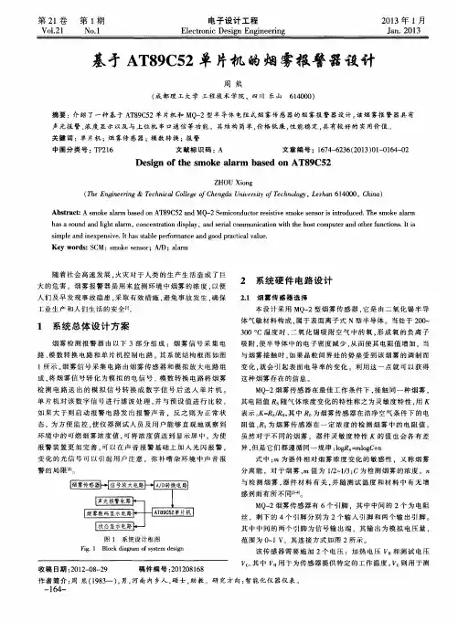
基于单片机的烟雾检测系统摘要为了早期发现和通报有害烟雾,防止和减少危害,保护人身和财产安全。
烟雾报警器能给人们提前警示。
随着“信息时代”的到来,传感器技术得到了显著的进步,其应用领域越来越广泛,对其需求越来越迫切,要求越来越高。
本文采用MQ-7型半导体电阻式烟雾传感器和AT89C2051单片机为核心技术设计的烟雾报警器,实现了烟雾报警、报警限设置、延时报警及与上位机串口通信等功能,对烟雾检测报警的实现技术进行了的有意义的探索与研究,在有害气体监测实现方面有一定的参考价值。
关键词烟雾报警器AT89C2051 传感器SMOKE DETECTION SYSTEM BASEDON SINGLE CHIPAbstractFor early detection and notification of harmful fumes, to prevent and reduce hazards and protect life and property safety. Smoke alarm can give people advance warning. With the "information age" the arrival of sensor technology has been significant progress, more and more widely its applications, its demand for more and more urgent, requiring higher and higher. In this paper, MQ-7-type semiconductor resistance type smoke sensor and AT89C2051 microcontrollers as the core technology smoke alarm designed to achieve a smoke alarm, alarm limit settings, delay alarm and serial communication with the host computer and other functions, the implementation of the smoke detection alarm Technology for a meaningful exploration and research, monitoring the achievement of the harmful gas have some reference value.KEY WORDS smoke alarm AT89C2051 sensor目录中文摘要 (I)英文摘要 (II)1 绪论 (1)1.1 问题由来 (1)1.2 课题现状 (2)1.3 论文的主要任务 (2)2 系统原理概述 (4)2.1 烟雾检测报警器的设计思路 (4)2.2 系统硬件组成原理 (4)2.3 烟雾传感器的选择 (5)2.4 运放与A/D的选择 (6)2.5 单片机系统部分 (9)2.5.1 单片机AT89C51介绍 (9)2.5.2 定时/计数器的结构及控制 (10)2.5.3 中断控制 (11)2.5.4 单片机外围电路介绍 (12)2.6 报警部分 (13)2.7 软件系统工作流程 (15)2.7.1 工作过程及程序设计 (16)3 系统设计 (17)3.1 系统的硬件设计 (17)3.2 软件设计 (19)3.2.1 A/D采样双通道流程 (19)3.2.2 报警流程设计 (20)4 系统的仿真 (23)4.1 A/D转换的仿真 (24)4.2 滤波及报警算法调试 (25)5 设计总结 (27)5.1 实现目标与特点 (27)5.2 结论及不足 (28)致谢 (29)参考文献 (30)附录1 (32)附录2 (33)1 绪论1.1问题由来随着社会的发展,人们对生活质量的要求越来越高,环境污染问题对人们的危害也越来越明显。
基于单片机的烟雾探测报警器外文翻译编辑整理:尊敬的读者朋友们:这里是精品文档编辑中心,本文档内容是由我和我的同事精心编辑整理后发布的,发布之前我们对文中内容进行仔细校对,但是难免会有疏漏的地方,但是任然希望(基于单片机的烟雾探测报警器外文翻译)的内容能够给您的工作和学习带来便利。
同时也真诚的希望收到您的建议和反馈,这将是我们进步的源泉,前进的动力。
本文可编辑可修改,如果觉得对您有帮助请收藏以便随时查阅,最后祝您生活愉快业绩进步,以下为基于单片机的烟雾探测报警器外文翻译的全部内容。
淮阴工学院毕业设计(论文)外文资料翻译学院:江淮学院专业:电子信息工程姓名:学号:外文出处:International Conference onElectricaland Control Engineering附件:1。
外文资料翻译译文;2.外文原文。
附件1:外文资料翻译译文温度控制系统的设计摘要:研究了基于AT89S 51单片机温度控制系统的原理和功能,温度测量单元由单总线数字温度传感器DS18B 20构成.该系统可进行温度设定,时间显示和保存监测数据。
如果温度超过任意设置的上限和下限值,系统将报警并可以和自动控制的实现,从而达到温度监测智能一定范围内。
基于系统的原理,很容易使其他各种非线性控制系统,只要软件设计合理的改变。
该系统已被证明是准确的,可靠和满意通过现场实践。
关键词:单片机;温度;温度I. 导言温度是在人类生活中非常重要的参数.在现代社会中,温度控制(TC)不仅用于工业生产,还广泛应用于其它领域。
随着生活质量的提高,我们可以发现在酒店,工厂和家庭,以及比赛设备。
而比赛的趋势将更好地服务于整个社会,因此它具有十分重要的意义测量和控制温度。
在AT89S51单片机和温度传感器DS18B20的基础上,系统环境温度智能控制。
温度可设定在一定范围内动任意。
该系统可以显示在液晶显示屏的时间,并保存监测数据,并自动地控制温度,当环境温度超过上限和下限的值。
DOC-火灾报警器中英文文献翻译--基于单片机的火灾探测和监控系统-单片机外文文献原稿和译文原稿Multiple single-chip microcomputer approach tofire detection and monitoring systemA.J. AI-Khalili, MSc, PhDD. AI-Khalili, MSc, PhDM.S. Khassem, MScIndexing term : Hazards, Design, Plant condition monitoringAbstract: A complete system for fire detection and alarm monitoring has been proposed for complex plants. The system uses multiple single chip architecture attached to a party line. The control algorithm is based on a two-level hierarchy of decision making, thus the complexity is distributed. A complete circuit diagram is given for the local and the central station with requirements for the software structure. The design is kept in general form such that it can be adapted to a multitude of plant configurations. It is particularly shown how new developments in technology, especially CMOS single chip devices, are incorporated in the system design to reduce the complexity of theoverall hardware, e.g. by decomposing the system such that lower levels of hierarchy are able to have some autonomy in decision making, and thusa more complex decision is solved in a simple distributed method. 1 IntroductionRegulatory requirements for most high risk plants and buildings mandate the installation of fire detection and warning systems for all sensitive areas of the plant orthe building. Most fire codes state the requirement for monitoring and control pecifically related to a type of a plant or building such as chemical plants, petroleum, snuclear plants, residential high-rises etc. A general conclusion of these codes can be specified as the following requirements :(a) The source of all detector signals should be exactlyidentifiable by the central station(b) An extra path of communication between the central station andall local controllers(c) Direct means of control of alarm and central equipment by the central station(d) Means of communication between the central station and the fire department(e) Availability of emergency power supply. The codes usually also specify the types and frequency of tests for all equipment.A fire detection and alarm system is a combination of devices designed to signal an alarm in case of a fire. The system may also accomplish fan control, fire door hold or release, elevator recall, emergency lighting control and other emergency functions. Theseadditional functions supplement the basic system which consists of detection and alarm devices and central control unit.Technology has an influence on system architecture. When technology changes, the architecture has to be revised to take advantage of these changes. In recent years, VLSI technology has been advancing at an exponential rate. First NMOS and, in the last year or two, CMOS chips have been produced with the same packing density with more gates per chip yet at a lower power consumption than NMOS. Surely this change in technology must affect our design of hardware at both the chip and the system level. At the chip level, single chips are now being produced which are equivalent to board levels of only the previous year or two. These chips have microprocessor, memory in RAM and ROM, IO Ports both serial and parallel, A/D timer, flags and other functions on chip. At the system level, the new chips make new architectures possible. The objective of this paper is to show how technology can influence system architecture in the field of fire control. The new high density single chip microcontrollers are incorporated in the design of a large scale system and yet weobtain a smaller system with a better performance. In terms of fire detection and alarm monitoring, this is reflected directly in the local station hardware, because of their remoteness and power supply requirements. A complete local station can be designed around a single CMOS chip with power consumption of a few m W depending on system operation. This approach reduces the cost and complexity of design,implementation and maintenance and provides easily expandable and portable design. This implementation was not possible with old technology. Most of fire detection/monitoring systems available are tailored towards a specific application and lack the use of recent advances in CMOS VLSI technology. In this study, we develop a fire detection/monitoring system which is general in concept, readily implementable in a multitude of applications for early detection of a fire before it becomes critical, for equipment and evacuation of personnel. Here, we propose a central control and distributedcontrol/detection/monitoring with adequate communication, where use is made of single-chip microcontrollers in the local stations, thus improving controllability and observability of the monitoring process.2 Detection and alarm devicesA basic fire detection system consists of two parts, detection and annunciation. An automatic detection device, such as a heat, smoke or flame detector, ultraviolet or infrared detectors or flame flicker, is based on detectingthe byproduct of a combustion. Smoke detectors, of both ionization and optical types, are the most commonly useddetector devices. When a typical detector of this type enters the alarm state its current consumption increasesfrom the pA to the mA range (say, from a mere 15pA in the dormant mode to 60 mA) in the active mode. Inmany detectors the detector outputvoltage is well defined under various operating conditions, such as thosegiven in Table 1. Themore sensitive the detector, themore susceptible it is to falsealarms. In order to control the detector precisely, either of the following methods is used: a coincidence technique can be built into the detector, or a filtering technique such that a logic circuit becomes active only if x alarms are detected within a time period T. The detection technique depends greatly on the location and plant being protected; smoke detectors are used for sleeping areas, infrared or ultraviolet radiation are used when flammable liquids are being handled, heat detectors are used for fire suppression or extinguishing systems. In general, life and property protection have different approaches.Alarm devices, apart from the usual audible or visible alarms, may incorporate solid state sound reproduction and emergency voice communication or printers that record time, date, location and other information required by the standard code of practice for fireprotection for complex plants. Heaviside [4] has an excellent review of all types of detectors and extinguisher systems.2.1 Control philosophy and division of labourOur control philosophy is implemented hierarchically. Three levelsof system hierarchy are implemented, with two levels of decision making. There is no communication between equipment on the same level. Interaction between levels occurs by upwards transfer of information regarding the status of the subsystems and downwards transfer of commands. This is shown in Fig. 1 where at level 1 is the centralstation microcomputer and is the ultimate decision maker (when not in manual mode). At level 2 are the local controllers, which reside in the local stations. At level 3 are the actual detectors and actuators. A manual mode of operation is provided at all levels.Information regarding the status of all detectors is transmitted on a per area basis to the local controllers. Their information is condensed and transmitted upward to the central microcomputer. Transfer of status is always unidirectional and upwards. Transfer of commands is always unidirectional and downwards, with expansion at the local control level. This approach preserves the strict rules of the hierarchy for exact monitoring detection and alarm systems associated with high risk plants.The classification of the two layers of controls is based uponlayers of decision making, with respect to the facts that(a) When the decision time comes, the making and implementation of a decision cannot be postponed(b) The decisions have uncertainty(c) It will isolate local decisions (e.g. locally we might have an alarm although there may be a fault with the system)3 General hardwareI :Fig. 2 depicts our design in the simplest of forms. The system uses an open party line approach with four conductor cables going in a loop shared by all the remote devices and the control panel. This approach is simple in concept and is economically feasible. However, one major disadvantage is the dependency on a single cable for power andsignaling. In cases where reliability is of extreme importance, two or even three cables taking differentroutes throughout the system may be connected in parallel. Fig. 3 gives the driver circuitry required to derive an expandable bus. This design takes advantage of recent advances in the single chip microcomputer technology to reduce the interface between the central station and the local stations.3. 1 Central control taskA central unit provides a centralized point to monitor and control the systemactivities. In the system to be described the central control unit serves a fivefold purpose.(i) It receives information from the local stations and operates the alarms and other output devices.(ii) It notifies the operator in case of system malfunction.(iii) It provides an overall system control manual and automatic.(iu) It provides a system test point of local stations and itself.(u) It provides a central point for observation, learning and adaptation.3.2 Local stationsThe local stations can take local decisions regarding recognition of a risk situation, and act independently on local affairs. In this technique we depend on ‘load-type coordination’, e.g. the lower level units recognize the existence of otherdecision units on the same level; the central or the top level provides the lower units with a model of the relationship between its action and the response of the system.It is evident that a powerful machine is required at this stage so that all the required functions can be implemented. The availability of the new generation of microchips makes this architecture a feasible solution.A single chip microcomputer was chosen over discrete digital and analogue devices to interface to the field devices and to the central microcomputer. This is the main reason that previously this approach was not feasible.In selecting the microcomputer for the local stations, the criterion was the requirement for a chip which contains the most integration ofthe analogue and digital ports required for the interface and the utilization of CMOS technology owing to remoteness of the local stations. The choice was the Motorola 68HC11A4, for the following reasons:(a) It is CMOS technology; this reduces power consumption.(b) It has a UART on board; this facilitates serial communication.(e) It has an a/d converter on board; this eliminates an externalA/D.(d) It has 4K of ROM, 256 bytes of RAM, 512 bytes of EERROM with 401/0 lines and a 16 bit timer; this satisfied all our memory and 1/0 requirements at the local station side.4 System implementationThe local station: Fig. 3 is the block diagram of the circuit usedto utilize the MC68HCllA4 as a remote fire detecting circuit while Fig.4 illustrates the same circuit in an expanded form. It can be seen that the single microcontroller can be used to monitor more than one detector, thus reducing system cost.The loop power supply, which is usually between 28 and 26 V, isfurther regulated by a 5 V 100 mA monolithic low power voltage regulator to supply power to the microcontroller. The onboard oscillator, coupled with an external crystal of 2.4576 MHz, supplies the microcontrollerwith its timing signal which is divided internally by four to yield aprocessor frequency of 614.4 kHz, which is an even multiple of the RS 232 [7] baud rate generator. In this Section the term ‘supervised input or output’ will be used to mean that the function in question is monitored foropen- and short-circuit conditions in addition to its other normal functions. More information can be found in Reference 9.5 Main loop6 ConclusionThis paper describes the development of a large scale fire detection and alarm system using multi-single chip microcomputers. The architecture used is a two-level hierarchy of decision making. This architecture is made possible by the new CMOS microcontrollers which represent a high packing density at a low power consumption yet are powerful in data processing and thus in decision making. Each local station could make an autonomous decision if the higher level of hierarchy allows it to do so. It has been tried to keep the system design in general format so it can be adapted to varying situations. A prototype of the described system has been built and tested [10]. The control part of the central station is implemented with a development card based on MC 68000 microprocessor (MEX 68KECB, by Motorola), which has a built-inmonitor called Tutor. The application programs were developed using the features provided by this monitor. The local stations’ controllers were designed using the MC68705R3, single-chip microcontroller.7 References1 ‘Fire protection guidelines for nuclear power plants’, US NRC Regulatory Guide 1.1202 BAGCHI, C.N.: ‘A multi-level distributed microprocessor systemfor a nuclear power plant fire protection system controls, monitoring, and communication’, IEEE Trans., 19823 PUCILL, P.M.: ‘Fire hazard protection, detection and moni toring systems’, Sea. Con, 2, Proceedings of Symposium on ADV in offshore and terminal measurement and control systems, Brighton, England, March 1979, pp. 353-3634 HEAVISID, L.: ‘Offshore fire and explosion detection and fixed fire’. Offshore Technologic al Conference, 12th Annual Proceedings, Houston, Texas, May 1980, pp. 509-5225 CELLENTANI, E.N., and HUMPHREY, W.Y.: ‘Coordinateddetection/communication approach to fire protection’, Specify: Eng.,6 ‘Motorola Microprocessors Data Manual’ (Motorola Se miconductor Products, Austin, Texas, USA)7 Electronic Industries Association : ‘Interface between data terminal equipmentand data communication equipment employing serial binary data interchange’ (EIA Standard RS-232, Washington, DC, 1969)8 MESAROVIC, M.D., MACKO, D., TAKAHARA, Y.: ‘Theory of hierarchical multilevel systems’ (Academic Press, 1970)9 KASSEM, M.: ‘Fire alarm systems’, MSc. thesis, Dept. of Elec. & Comp. Eng., Concordia University, Montreal, Canada, 198510 LIE, P., and KOTAMARTI, U.: ‘The design of a fire alarm system using microprocessors’, C481 Project, Dept. of Elec. and Comp. Eng., Concordia University,Montreal, Canada, 1986译文基于单片机的火灾探测和监控系统A.J. AI-Khalili, MSc, PhDD. AI-Khalili, MSc, PhDM.S. Khassem, MSc关键词:危险,设计,设备状态监测摘要:火灾探测及报警监控已成为一个复杂而完整的体系。
火灾报警器中英文对照外文翻译文献(文档含英文原文和中文翻译)Automatic fire alarm systemThe traditional electron safe alarm system mainly is through the sensor automatic detection, produces the alarm, sends out the alarm the scene or reports to the police through the special electric near distance, thus causes people's vigilance. Through many years research and the development, the present alarm apparatus may say is the class is multitudinous. As a result of the alarm apparatchik development and the social each domain anxious need, can application domain be more and more many, specially is overdevelops in the civil domain.In recent years, the infrared alarm apparatus already became reports to the police a domain hot spot,because it used was not the obviously infraredacquisition, Hereford the hiding to be good, characteristic and so on security. Infrared sensor is different according to the mechanism may divide into the light survey and the hot survey. The light acquisition sensor is uses the photon effect the acquisition aid. This kind of sensor speed of response quick, sensitive high, the examination characteristic is good, but needs cool, uses not conveniently. Moreover the component examination sensitivity and the infrared wave length concern. The hot acquisition is uses hotly releases the electricity effect the acquisition aid. After receives the goal the infrared misinterpretation increment, the temperature elevates causes the censorial certain physical quantities changes, through examination physical quantity change definite infrared emission. This kind of sensor works under the room temperature condition, examination sensitivity also very high, speed of response also very quick,moreover has nothing to do with with the infrared emission wavelength, may survey the power only to receive the background irradiation limit, the application is very convenient. This article designs atheist passive form hotly releases the electricity infrared acquisition aid. In the article mainly elaborated has hotly released electrician the principle, hotly releases content and so on Malayalam circuit which the electric detector the characteristic,the BISSAU signal processor, 555 timers composed. Finally designed completes has hotly released the electricity infrared detection alarm apparatus the hardware electric circuit.With the modern family use of fire, electricity consumption increases, the frequency of home fires is getting higher and higher. The family of fire, it iseasy to fight does not occur promptly, the lack of fire-fighting equipment and the presence of panic-stricken people, to escape unfavorable factors, such as retardation, which eventually led to a significant loss of life and property. Explore the characteristics of the family of fire and fire prevention measures. For the prevention of domestic fires, reducing the fire losses have practical significance. In the modern urban family, because of lot of people do not understand common sense home security caused by fire, so that the happy family Geog underlined blink of an eye, and some lead to destruction, but the event of household fires, improper disposal, alarm delay is caused so that people should get to know more about the main causes of household fires, master to prevent the fire of knowledge and in case of fire to protect his or her own way, timely elimination of The United Kingdom each year more than 50000 families of serious fires, most of them fire casualties and significant loss of household assets, and some result in the neighbors, more heavy fire losses. Investigate the causes of fire in time, the vast majority of home fires happen parties said that the fire always feel that things are other people with their own far away, did not think this will happen even in the top of his head.Home fires are the main reason for negligent not to take timely preventive measures .In some of our large and medium-sized cities, almost every day family fires, fire prevention is so each family must always pay attention to. If your home based on the actual situation in advance to take simple fire prevention measures, a number of tragedies are entirely avoidable.Automaticfire alarm system is in order to inform the early detection of fire, and t ake effective measures to control and fight fires, and set in a building or other pl ace of an automatic fire facilities, is that people with a powerful tool to fight the fire. Fire alarm system, fire detectors generally, regional centralized alarm alarm and composition; also be required under the project with various fire-fighting fa cilities and communication devices linked to form a central control system. Fro m automatic alarm, automatic fire fighting, evacuation guidance, system process shows that, fire up a complete file management, fire control system. Fire detect ors are fire detection devices, as in the stage of fire will produce smoke with hig h temperature flame cells. The smoke, heat and light into electrical signals throu gh the detector alarm or automatic fire extinguishing system to start fighting the fire in time. Area where the floor of alarm detector can send the signal into soun d and light alarm, and fire on the screen showing the room number; while also m onitoring the concentration of certain floors of alarm (if the monitor is located in the building fire Control Center) output signal or control automatic fire extingui shing system. Concentration of alarm signal is received by way of sound and lig ht show, and the screen also shows the specific fire floor and room number, the plane stopped taking the first alarm clock to record the timing, use of the machin e-specific phones, but also quickly to the fire alarm to give directions and. In ad dition, you can control the fire extinguishing system or signal transmission to th e fire control room.Automatic fire alarm system is by the trigger devices, fire alarm, fire alarm devices and other auxiliary functions of the device with the composition of a bu tton fire alarm system fire alarm system. It can fire early stages of burning smok e, heat and light radiation and other physical quantities, by temperature. Photogr aphic and other smoke and fire detectors into electrical signals, transmitted to th e fire alarm controller, and also shows the site of the fire, the fire record of the ti me. General fire alarm system and automatic sprinkler system, fire hydrant syste ms, smoke control systems, ventilation systems, air conditioning system, fire do ors, fire shutter, smoke screen and other related equipment interaction, automati cally or manually issue commands to start the corresponding device.(A) of the trigger devices in automatic fire alarm system, automatic or man ual fire alarm signal devices generate called trigger conditions, including fire det ectors and manual fire alarm button. Fire detector is able to fire parameters (smo ke, temperature, flame radiation, gas concentration, etc.) response, and automati cally generate a fire alarm signal devices. Fire response parameters according to different fire detectors into heat detectors, smoke detector, sensitive fire detector s, combustible gas detectors and fire detectors five basic types of composite. Dif ferent types of fire detectors for different types of fires and different places. Man ual fire alarm button fire alarm signal generated manually start the automatic fire alarm system devices, automatic fire alarm system is an indispensable compone nt of the.(B) the fire alarm device in automatic fire alarm system to receive, display and transmit fire alarm signals, and can send control signals and control function s with other auxiliary equipment as the fire alarm device instructions. Fire alarm control is one of the most basic kind. Charged with the fire alarm control fire det ectors provide a stable working power; detector and the working status of the sy stem itself; the reception, conversion, processing a warning of fire detectors Shu ck; Jinxing sound and light alarm; Hashish specific location and alarm time; the same time supporting the implementation of appropriate control and many other tasks. Fire alarm system is a core component. In the fire alarm devices, some de vices such as break, regional monitors, fire shows and other functions can not co mplete disc alarm device, which can be regarded as the evolution of fire alarm c ontroller or supplement. Under certain conditions applied, and the fire alarm dev ice fire alarm control belong. The basic function of fire alarm control are: the m ain power, backup power automatically converted, standby power charge functio n, power failure monitoring function, power functions working status indicator, power supply for the detector circuit function, control sensors or system failures, sound and light alarm, fire sound, light alarm, fire alarm and memory function, clock function unit, with priority being given fault function fire alarm, sound ala rm sound audible alarm mute and again.(C) fire alarms in automatic fire alarm system to send different from the e nvironment, sound, light the fire alarm signal device called the fire alarms. It sound, light and sound approach to the issue of fire alarm signals alarm area to warn people to adopt safe evacuation, fire fighting and rescue measures.(D)Fire control equipment in automatic fire alarm system, when receivin g the fire alarm, automatically or manually start the related fire-fighting equipme nt and display devices of their state, known as the fire control equipment. Includ e fire alarm control, automatic fire extinguishing system control device, fire hyd rant system control devices, smoke exhaust system and air conditioning and vent ilation system control device, normally open fire doors, fire shutter control devic e, the lift back down control equipment, and fire emergency radio, fire alarms, fi re communications equipment, fire evacuation signs and emergency lighting con trol devices, control devices in some or all. Fire control equipment normally inst alled in the fire control center to facilitate the implementation of centralized cont rol. While others set fire control equipment, fire fighting equipment is located i n the charged field, but its actions must be returned fire control signal, combined with the implementation of centralization and decentralization of control(E) fire alarm system power supply electrical equipment belonging to the fi re, the main power should be in the fire power, standby power use of battery. In addition to fire alarm system power controller, power supply, but also related to the system for the fire control equipment such as power supply.火灾自动报警系统传统电子安全报警系统主要是通过传感器自动检测,产生报警信号,从现场发出报警信号或通过专门电缆近距离报警,从而引起人们的警觉。
本科生毕业设计(翻译)专业:电子信息工程学生:指导教师:完成日期: 2013年03月日多功能智能无线报警系统摘要:利用内部资源丰富的FPGA(现场可编程门阵列),设计了一个无线报警发送系统。
它包括编码器,FSK(频移键控)调制和每个通道的控制电路,它可以减小报警系统的体积同时提高其可靠性,解调接收系统的实现基于一个应用特定程序的集成电路MC3372。
在一个单片机89C51的帮助下,地址解码器也设计在接收器中。
添加其他反干扰功能,有效地降低报警系统的错误警报率。
该系统可以安装多达128个通道的发送设备。
有某些情况下,在有突发情况时,它可以发送报警信号至主机,系统会循环显示多个突发情况所在的区域代码。
传输距离是大于4公里的开阔地带。
用户可以同时安装多个类型的传感器,例如,烟雾传感器,可燃气体传感器或防盗传感器。
实验表明,无线报警系统具有高可靠性,高抗干扰能力和低错误警报率的优势。
它可以完全满足对防火防盗需要。
关键词:通讯;报警系统;频移键控;微控制器;现场可编程门阵列一、前言无线报警系统与有线警报系统相比,具有隐蔽性和易于安装的特点。
它在复杂的地形地貌情况之间的长距离传输时特别有效。
由FPGA(现场可编程门阵列)组成,其编码模块在发送系统创建地址信号,FSK(频移键控)调制信号及每个通道的控制器信号。
用FPGA取代MSI /SSI (中等规模的综合或小规模的综合)数字电路设备,不仅提高报警系统的可靠性和干扰阻力,同时也降低了它的体积,使系统更易于安装。
由于使用7位二进制数表示地址,最多可以安装为128个收发通道。
解码器由ASIC(特定用途集成电路)和SCM(单芯片微机)在无线报警接收机系统,它可以有效地降低错误警报率。
二、发送系统原理每个基站安装一个无线发送系统,并与一个7位二进制地址标识符相对应。
一旦在任何一个基站中传感器检测到突发情况,该区域的控制信号发送至编码电路,通过编码再接入该区域的7位地址标识的接口电路,转换成FSK信号。
毕业设计基于单片机的烟雾检测报警系统毕业设计(论文)原创性声明和使用授权说明原创性声明本人郑重承诺:所呈交的毕业设计(论文),是我个人在指导教师的指导下进行的研究工作及取得的成果。
尽我所知,除文中特别加以标注和致谢的地方外,不包含其他人或组织已经发表或公布过的研究成果,也不包含我为获得及其它教育机构的学位或学历而使用过的材料。
对本研究提供过帮助和做出过贡献的个人或集体,均已在文中作了明确的说明并表示了谢意。
作者签名:日期:指导教师签名:日期:使用授权说明本人完全了解大学关于收集、保存、使用毕业设计(论文)的规定,即:按照学校要求提交毕业设计(论文)的印刷本和电子版本;学校有权保存毕业设计(论文)的印刷本和电子版,并提供目录检索与阅览服务;学校可以采用影印、缩印、数字化或其它复制手段保存论文;在不以赢利为目的前提下,学校可以公布论文的部分或全部内容。
作者签名:日期:学位论文原创性声明本人郑重声明:所呈交的论文是本人在导师的指导下独立进行研究所取得的研究成果。
除了文中特别加以标注引用的内容外,本论文不包含任何其他个人或集体已经发表或撰写的成果作品。
对本文的研究做出重要贡献的个人和集体,均已在文中以明确方式标明。
本人完全意识到本声明的法律后果由本人承担。
作者签名:日期:年月日学位论文版权使用授权书本学位论文作者完全了解学校有关保留、使用学位论文的规定,同意学校保留并向国家有关部门或机构送交论文的复印件和电子版,允许论文被查阅和借阅。
本人授权大学可以将本学位论文的全部或部分内容编入有关数据库进行检索,可以采用影印、缩印或扫描等复制手段保存和汇编本学位论文。
涉密论文按学校规定处理。
作者签名:日期:年月日导师签名:日期:年月日注意事项1.设计(论文)的内容包括:1)封面(按教务处制定的标准封面格式制作)2)原创性声明3)中文摘要(300字左右)、关键词4)外文摘要、关键词5)目次页(附件不统一编入)6)论文主体部分:引言(或绪论)、正文、结论7)参考文献8)致谢9)附录(对论文支持必要时)2.论文字数要求:理工类设计(论文)正文字数不少于1万字(不包括图纸、程序清单等),文科类论文正文字数不少于1.2万字。
外文翻译--基于51单片机温度报警器的设计(适用于毕业论文外文翻译+中英文对照)XXX: Design of a Temperature Alarm Based on 51 MCUDepartment: n EngineeringMajor: Measurement and Control Technology and nClass:Student ID:Name:Supervisor:Date:A microcontroller。
also known as a single-chip computer system。
XXX its ns being integrated on a small chip。
it has most of the components needed for a complete computer system。
such as CPU。
memory。
internal and external bus systems。
and mostof them also have external storage。
At the same time。
it integrates XXX interfaces。
timers。
real-time clocks。
etc。
The most XXX integrate sound。
image。
ork。
and complex input-output systems on a single chip.XXX used in the industrial control field。
Microcontrollers XXX CPUs inside the chip。
The original design concept was to integrate a large number of peripheral devices and CPUs on a chip to make the computer system XXX's Z80 was the first processor designed according to this concept。
基于单片机的烟感报警器摘要本设计设计一个烟感报警器,通过传感器 (包括温感和烟感)将现场温度、烟雾等信号转化为可检测的电信号,放大和滤波电路将传感器输出的电信号送入A /D转换电路 ,完成烟雾传感器和温度传感器输出的模拟信号到数字信号的转换,单片机判断现场是否发生火灾。
若发生火灾,系统会驱动蜂鸣器和指示灯报警。
由于系统采用高性能的单片机芯片为核心和高灵敏度的烟感传感器,而且利用声音和指示灯两种报警形式进行报警提示,大大的提好了系统的精确性和可靠性。
关键词单片机 AT89C51 ADC0809 传感器SummaryThe design of the design of a smoke alarm, the scene temperature, smoke, etc. signal into electrical signal detected by the sensors (including temperature sensitive and smoke), amplification and filtering circuit of the sensor output electrical signal fed to the A / D converter circuit, the completion of the smoke sensor and temperature sensor output analog signal to digital signal conversion, the microcontroller to determine whether the site fire. If a fire occurs, the system will drive the buzzer and the alarm indicator.As the system uses high-performance microcontroller chip as the core and high sensitivity smoke sensors, and the use of sound and light form of two alarm alarm, much of the good accuracy and reliability of the system.Keywords AT89C51 MCU; ADC0809 sensor目录1 引言 (4)1.1 课题研究的背景和意义 (4)1.2本文内容的结构安排 (4)2 火灾报警系统整体方案设计 (5)2.1火灾的烟雾产生过程和温度升高过程 (5)2.2.1 系统硬件总体构架 (6)2.2.2 系统软件总体构架 (7)2.3系统主要器件的选择 (8)2.3.1 传感器的选择 (8)2.3.2 单片机芯片的选择 (12)2.3.3A/D转换芯片的选择 (13)3 火灾自动报警系统硬件设计 (14)3.1 信号放大和滤波电路 (14)3.2晶振电路与复位电路 (16)3.2.1晶振电路 (16)3.2.2 复位电路 (17)3.3声光报警电路 (17)3.3.1声音报警器 (17)3.3.2光报警器 (18)3.4 数据采集电路 (18)4 火灾报警系统程序设计 (21)4.1软件开发环境 (21)4.2火灾报警系统程序设计 (21)4.2.1 据采集程序 (22)4.2.2火灾判断与报警程序 (23)4.3软件调试 (24)5 总结 (25)参考文献 (27)附录............................................... 错误!未定义书签。
基于单片机的烟雾报警器设计任务书1.任务目的:设计一个基于单片机的烟雾报警器,可以实时监测空气中的烟雾浓度,当浓度超过预设阈值时发出警报。
Purpose of the task: To design a smoke alarm based on a single-chip microcomputer, which can monitor the smoke concentration in the air in real time and sound an alarm when the concentration exceeds the preset threshold.2.任务背景:烟雾报警器是一种重要的安全设备,可以在发生火灾时迅速发出警报,提醒人们及时逃生。
Background of the task: The smoke alarm is an important safety device that can sound an alarm quickly in the event ofa fire, reminding people to evacuate in time.3.任务范围:设计一个可靠、灵敏的烟雾报警器原型,具有良好的环境适应性和抗干扰能力。
Scope of the task: Design a reliable and sensitive prototype of the smoke alarm, with good environmental adaptability and anti-interference ability.4.任务要求:烟雾报警器应具有自检功能,能够检测传感器和报警电路的正常工作状态。
Requirements of the task: The smoke alarm should have a self-check function, which can detect the normal operation status of the sensor and the alarm circuit.5.任务方法:采用单片机作为主控芯片,配合烟雾传感器和报警电路,设计并制作烟雾报警器原型。
• 132•基于STM32F103单片机的烟雾报警器设计山东科技大学信息工程系 孙 波山东科技大学机电工程系 刘士彩山东科技大学信息工程系 王玉潇山东科技大学网络中心 张家迎山东科技大学机电工程系 高学辉山东科技大学信息工程系 郭 帅为了避免火灾以及减少火灾造成的损失,必须设计和完善火灾自动报警系统,将火灾消灭在萌芽状态,最大限度地减少社会财富的损失。
本文介绍了一个在较小范围内使用的单片机烟雾报警系统,此系统以STM32F103单片机为控制器,通过NIS-07离子式烟雾传感器检测信号,经单片机本身的数模转换器进行信号转换后,输入到单片机,然后利用数码管显示烟雾浓度,通过单片机的蜂鸣器实现报警功能。
1.引言近些年,越来越多的地方频繁的发生火灾,引起了人民群众的广泛关注。
火灾预警对于保护个人以及个人的财产安全具有重要的意义。
目前市场上存在的烟雾报警器价格比较高,不适合小范围进行使用,如家庭、学校、小型商场等。
本文提出了一种基于单片机的小型烟雾报警器,价格低,单片机本身带有数模转换器,适合小范围进行使用,且STM32F103单片机芯片集成了定时器,CAN ,ADC ,SPI ,I2C ,USB 和UART 等多种功能,已被广泛使用到多个领域。
2.器件介绍2.1 单片机STM32F 具有72MHz 的工作频率,集成了存储器、电源管理、低功耗。
模数转换器、DMA 、调试模式、计算单元和封装等模块。
并且该芯片用途广泛,已普遍应用到电力电子系统方面。
STM32F103单片机的引脚图如图1所示。
图1 STM32F103单片机VBAT 引脚的作用是给RTC 和备份区域供电,保证在VDD 断电的情况下相关区域的数据内容仍然是有效的,一般连接到外部电池;PC13/PC14/PC15引脚的内部模拟了开关,只允许少量的电流通过,驱动能力小,不可以同时使用;当PA0-WKUP 引脚处于上升沿时,作为待机模式唤醒条件;每个VDD 各接一个0.1uF 陶瓷电容,VDD_3需要再接一个4.7~10uF 的钽电容;对于VDDA ,需要连接10nF 陶瓷电容+1nF 钽电容。
Design of the Temperature Control System Based on AT89S51ABSTRACTThe principle and functions of the temperature control system based on microcontroller AT89S51 a re studied, and the temperature measurement unit consists of the 1-Wire bus digital temperature sensor DS18B20. The system can be expected to detect the preset te mperature, display time and save monitoring data. An alarm will be given by system if the temperat ure exceeds the upper and lower limit value of the temperature which can be set discretionarily and then automatic control is achieved, thus the temperature is achieved monitoring intelligently within a certain range. Basing on principle of the system, it is easy to make a variety of other non-linear control systems so long as the software design is reasonably changed. The system has bee n proved to be accurate, reliable and satisfied through field practice.KEYWORDS: AT89S51; microcontroller; DS18B20; temperatureI. INTRODUCTIONTemperature is a very important parameter in human life. In the modern society, temperature contr ol (TC) is not only used in industrial production, but also widely used in other fields. With the impro vement of the life quality, we can find the TC appliance in hotels, factories and home as well. And t he trend that TC will better serve the whole society, so it is of great significance to measure and co ntrol the temperature.Based on the AT89S51 and temperature sensor DS18B20, this system controls the condition temp erature intelligently. The temperature can be set discretionarily within a certain range. The system can show the time on LCD, and save monitoring data; and automatically control the temperature w hen the condition temperature exceeds the upper and lower limit value. By doing so it is to keep th e temperature unchanged. The system is of high anti-jamming, high control precision and flexible design; it also fits the rugged environment. It is mainly used in people's life to improve the quality of the work and life. It is also versatile, so that it can be convenient to extend the use of the system. So the design is of profound importance. The general design, hardware design and software design of the system are covered.II. SYSTEM GENERAL DESIGNThe hardware block diagram of the TC is shown in Fig. 1. The system hardware includes the micro controller, temperature detection circuit, keyboard control circuit, clock circuit, Display, alarm, drive circuit and external RAM. Based on the AT89S51, the DS18B20 will transfer the temperature signa l detected to digital signal. And the signal is sent to the microcontroller for processing. At last the te mperature value is showed on the LCD 12232F. These steps are used to achieve the temperature detection. Using the keyboard interface chip HD7279 to set the temperature value, using the micro controller to keep a certain temperature, and using the LCD to show the preset value for controlling the temperature. In addition, the clock chip DS1302 is used to show time and the externalRAM 62 64 is used to save the monitoring data. An alarm will be given by buzzer in time if the temperature exceeds the upper and lower limit value of the temperature. III. HARDWARE DESIGN A. Microc ontrollerThe AT89S51 is a low-power, high-performance CMOS 8-bit microcontroller with 4K bytes of in-system programmable Flash memory. The device is manufactured using Atmel’s high-density nonvolatile memory technology and is compatible with the industry-standard 80C51 instruction set and pinout. The on-chip Flash allows the program memory to be reprogrammed in-system or by a conventional nonvolatile memory programmer. By combining a versatile 8-bit CPU with in-system programmable Flash on a monolithic chip, the Atmel AT89S51 is a powerful microcontroller which provides a highly-flexible and cost-effective solution to many embedded control applications. Minimum system of the microcontroller is shown in Fig. 2. In order to save monitoring data, the 6264 is used as an external RAM. It is a stati c RAM chip, low-power with 8K bytes memory. B. Temperature Detection CircuitThe temperature sensor is the key part in the system. The Dallas DS18B20 is used, which support s the 1-Wire bus interface, and the ON-BOARD Patented is used internally. All the sensor parts and the converting circuit are integrated in integrated circuit like a transistor [1]. Its measure range is -55℃ ~125 ℃, and the precision between -10℃ ~85 ℃ is ±0.5℃ [2 ,3]. The temperature collected by the DS18B20 is transmitted in the 1-Wire bus way, and this highly raises the system anti-jamming and makes it fit in situ temperature measurement of the rugged environment [4].There are two power supply ways for the DS18B20. The first is external power supply: the first pin of the DS18B20 is connected to the ground; the second pin serves as signal wire and the third is c onnected to the power. The second way is parasite power supply [5]. As the parasite power supply will lead to the complexity of the hardware circuit, the difficulty of the software control and the perfo rmance degradation of the chip, etc. But the DS18B20(s) can be connected to the I/O port of the mi crocontroller in the external power supply way and it is more popular. Therefore the external power su pply is used and the second pin is connected to the pin P1.3 of the AT89S51. Actually, if there are multipoint to be detected, the DS18B20(s) can be connected to the 1-Wire bus. But when the number is over 8, there is a concern to the driving and the more complex s oftware design as well as the length of the 1-Wire bus. Normally it is no more than 50m. To achieve distant control, the system can be designed in to a wireless one to break the length limit of the 1-Wire bus [6]. C. LCD CircuitThe LCD 12232F is used, which can be used to show characters, temperature value and time, and supply a friendly display interface. The 12232F is a LCD with 8192 128×32 pixels Chinese charact er database and 128 16×8 pixels ASCII character set graphics. It mainly consists of row drive/colu mn drive and 128×32 full lattice LCD with the function of displaying graphics as well as 7.5×2 Chin ese characters. It is in a parallel or serial mode to connect to external CPU [7]. In order to economi ze the hardware resource, the 12232F should be connected to the AT89S51 in serial mode with on ly 4 output ports used.The LCD grayscale can be changed by adjusting the variable resistor connected the pin Vlcd of the LCD. CLK is used to transmit serial communication clock. SID is used to transmit serial data. CS i s used to enable control the LCD. L+ is used to control the LCD backlight power. D. Clock Circuit The Dallas DS1302 is used, which is a high performance, low-power and real-time clock chip with RAM. The DS1302 serves in the system with calendar clock and is used to mo nitor the time. The time data is read and processed by the AT89S51 and then displayed by the LC D. Also the time can be adjusted by the keyboard.The DS1302 crystal oscillator is set at 32768Hz, and the recommended compensation capacitance is 6pF. The oscillator frequency is lower, so it might be possible not to connect the capacitor, and t his would not make a big difference to the time precision. The backup power supply can be connec ted to a 3.6V rechargeable battery. E. Keyboard Control CircuitThe keyboard interface in the system is driven by the HD7279A which has a +5V single power sup ply and which is connected to the keyboard and display without using any active-device. According to the basic requirements and functions of the system, only 6 buttons are neede d. The system's functions are set by the AT89S51 receiving the entered data. In order to save the external resistor, the 1×6 keyboard is used, and the keyboard codes are defined as: 07H, 0FH, 17 H, 1FH, 27H, 2FH. The order can be read out by reading the code instruction. HD7279A is connec ted to the AT89S51 in serial mode and only 4 ports are need. As shown in Fig. 6, DIG0~DIG5 and DP are respectively the column lines and row line ports of the six keys which achieve keyboard monitoring, decoding and key codes identification. F. Alarm CircuitIn order to simplify the circuit and convenient debugging, a 5V automatic buzzer is used in the alar m circuit [8]. And this make the software programming simplified. As shown in Fig. 7, it is controlled by the PNP transistor 9012 whose base is connected to the pin P2.5 of the AT89S51. When the te mperature exceeds the upper and lower limit value, the P2.5 output low level which makes the tra nsistor be on and then an alarm is given by the buzzer.G. Drive CircuitA step motor is used as the drive device to control the temperature. The four-phase and eight-beat pulse distribution mode is used to drive motor and the simple delay program is used to handle the time interval between the pulses to obtain different rotational speed. There are two output stat es for the step motor. One: when the temperature is over the upper value, the motor rotates revers ely (to low the temperature), while when lower than the lower limit value, the motor rotates normally (to raise the temperature); besides not equals the preset value. Two: when the temperature is at s omewhere between the two ends and equals the preset value, the motor stops. These steps are u sed to achieve the temperature control. In addition, the motor speed can also be adjusted by relative buttons. As shown in Fig. 8, the code data is input through ports A11~A8 (be P2.3~P2.0) of the A T89S51 and inverted output by the inverter 74LS04. Finally it is amplified by thepower amplifier 2803A to power the motor.IV. SOFTWARE DESIGNAccording to the general design requirement and hardware circuit principle of the system, as well a s the improvement of the program readability, transferability and the convenient debugging, the sof tware design is modularized. The system flow mainly includes the following 8 steps: POST (Power-on self-test), system initiation, temperature detection, alarm handling, temperature control, clock chip DS1 302 operation, LCD and keyboard operation. The main program flow is shown in Fig. 9. Give a little analysis to the above 8 tasks, it is easy to find out that the last five tasks require the real time ope ration. But to the temperature detection it can be achieved with timer0 timing 1 second, that is to sa y temperature detection occurs per second. The system initiation includes global variable definition , RAM initiation, special function register initiation and peripheral equipment initiation. Global variab le definition mainly finishes the interface definition of external interface chip connected to the AT89 S51, and special definition of some memory units. RAM initiation mainly refers to RAM processing. For example when the system is electrified the time code will be stored in the internal unit address or the scintillation flag will be cleared. The special function register initiation includes loading the ini tial value of timer and opening the interrupt. For example, when the system is electrified the timer i s initialized. The peripheral equipment initiation refers to set the initial value of peripheral equipmen t. For example, when the system is electrified, the LCD should be initialized, the start-up display should be called, the temperature conversion command should be issued firstly and the clock chip DS1302 should also be initialized. The alarm handling is mainly the lowering and the rai sing of temperature to make the temperatureremain with the preset range. When the temperature is between the upper and the lower limit value , it goes to temperature control handling, that is to say the temperature need to be raised or lowere d according to the preset value. By doing so make the condition temperature equal to the preset va lue and hence to reach the temperature target.V. CONCLUSIONThe temperature control system has the advantages of friendly human-computer interaction interface, simple hardware, low cost, high temperature control precision (error in the range of ±1 ℃), convenience and versatility, etc. It can be widely used in the occasions with -55℃ to 125℃ range, and there is a certain practical value.。