
FWSM Basic Configuration Example
Document ID: 98591
Introduction
Prerequisites
Requirements
Components Used
Related Products
Conventions
Background Information
Configure
Network Diagram
Configurations
Verify
Troubleshoot
Problem: Unable to pass the VLAN traffic from FWSM to the IPS Sensor 4270
Solution
NetPro Discussion Forums ? Featured Conversations
Related Information
Introduction
This document describes how to configure the basic configuration of the Firewall Services Module (FWSM)installed either in the Cisco 6500 Series Switches or Cisco 7600 Series Routers. This includes the
configuration of the IP address, default routing, static and dynamic NATing, Access Control Lists (ACLs)statements in order to allow the desired traffic or block the unwanted traffic, application servers like
Websense for the inspection of the internet traffic from the inside network, and the Webserver for the Internet users.
Note: In a FWSM High Availability (HA) scenario, the failover can only successfully sync when the license keys are exactly the same between the modules. Therefore, the failover cannot work between the FWSMs with different licenses.
Prerequisites
Requirements
There are no specific requirements for this document.
Components Used
The information in this document is based on these software and hardware versions:
Firewall Services Module that runs software version 3.1 and later
? Catalyst 6500 series switches, with the required components as shown:
Supervisor engine with Cisco IOS ? software, which is known as supervisor Cisco IOS, or
Catalyst operating system (OS). See Table for supported supervisor engine and software
releases.
a. ?
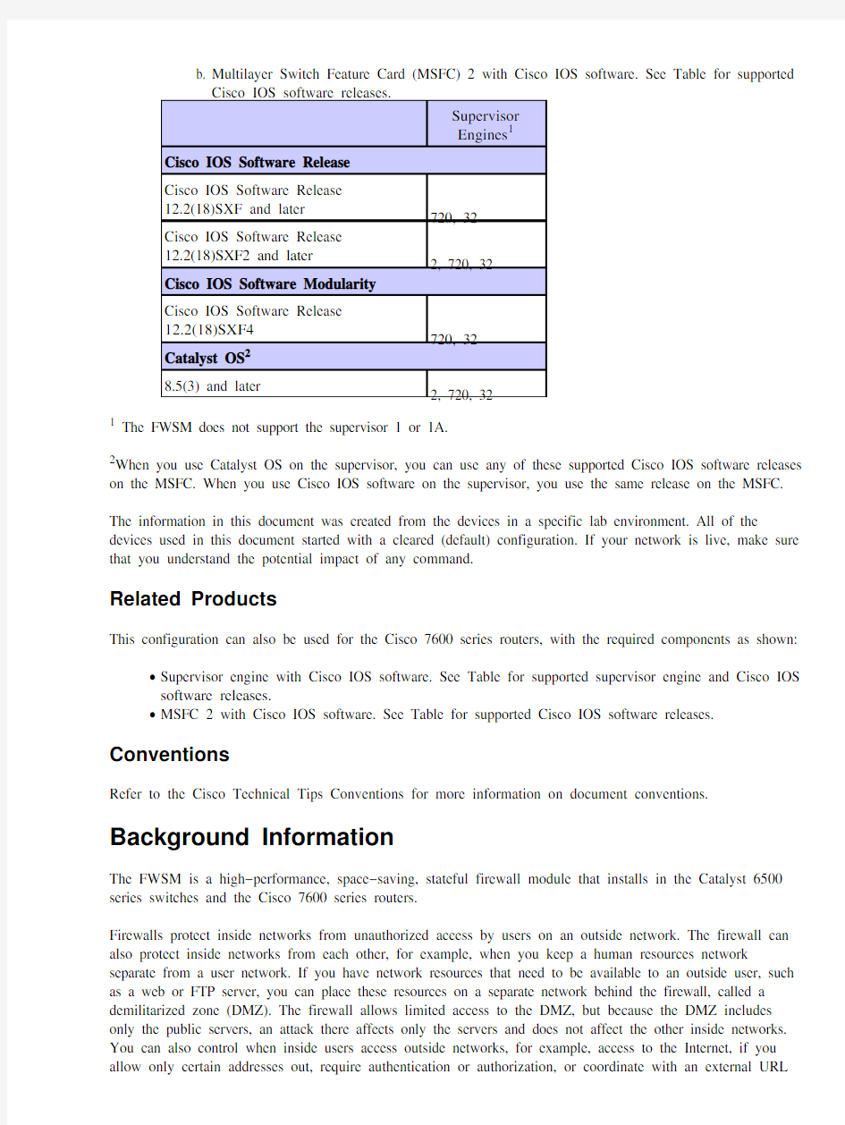
Multilayer Switch Feature Card (MSFC) 2 with Cisco IOS software. See Table for supported
b.
Cisco IOS software releases.
Supervisor
Engines1
Cisco IOS Software Release
Cisco IOS Software Release
12.2(18)SXF and later
720, 32
Cisco IOS Software Release
12.2(18)SXF2 and later
2, 720, 32
Cisco IOS Software Modularity
Cisco IOS Software Release
12.2(18)SXF4
720, 32
Catalyst OS2
8.5(3) and later
2, 720, 32
1 The FWSM does not support the supervisor 1 or 1A.
2When you use Catalyst OS on the supervisor, you can use any of these supported Cisco IOS software releases on the MSFC. When you use Cisco IOS software on the supervisor, you use the same release on the MSFC.
The information in this document was created from the devices in a specific lab environment. All of the devices used in this document started with a cleared (default) configuration. If your network is live, make sure that you understand the potential impact of any command.
Related Products
This configuration can also be used for the Cisco 7600 series routers, with the required components as shown:
?
Supervisor engine with Cisco IOS software. See Table for supported supervisor engine and Cisco IOS software releases.
?
MSFC 2 with Cisco IOS software. See Table for supported Cisco IOS software releases.
Conventions
Refer to the Cisco Technical Tips Conventions for more information on document conventions.
Background Information
The FWSM is a high?performance, space?saving, stateful firewall module that installs in the Catalyst 6500 series switches and the Cisco 7600 series routers.
Firewalls protect inside networks from unauthorized access by users on an outside network. The firewall can also protect inside networks from each other, for example, when you keep a human resources network separate from a user network. If you have network resources that need to be available to an outside user, such as a web or FTP server, you can place these resources on a separate network behind the firewall, called a demilitarized zone (DMZ). The firewall allows limited access to the DMZ, but because the DMZ includes only the public servers, an attack there affects only the servers and does not affect the other inside networks. You can also control when inside users access outside networks, for example, access to the Internet, if you allow only certain addresses out, require authentication or authorization, or coordinate with an external URL
filtering server.
The FWSM includes many advanced features, such as multiple security contexts that are similar to virtualized firewalls, transparent (Layer 2) firewall or routed (Layer 3) firewall operation, hundreds of interfaces, and many more features.
During the discussion of networks connected to a firewall, the outside network is in front of the firewall, the inside network is protected and behind the firewall, and a DMZ, while behind the firewall, allows limited access to outside users. Because the FWSM lets you configure many interfaces with varied security policies, which includes many inside interfaces, many DMZs, and even many outside interfaces if desired, these terms are used in a general sense only.
Configure
In this section, you are presented with the information to configure the features described in this document. Note: Use the Command Lookup Tool ( registered customers only) in order to obtain more information on the commands used in this section.
Network Diagram
This document uses this network setup:
Note: The IP addressing schemes used in this configuration are not legally routable on the Internet. They are RFC 1918 addresses, which have been used in a lab environment.
Configurations
This document uses these configurations:
Catalyst 6500 Series Switch Configuration
? FWSM Configuration
? Catalyst 6500 Series Switch Configuration
You can install the FWSM in the Catalyst 6500 series switches or the Cisco 7600 series routers. The
configuration of both series is identical and the series are referred to generically in this document as
the switch .
Note: You need to configure the switch appropriately before you configure FWSM.
1. Assign VLANs to the Firewall Services Module T his section describes how to assign VLANs to
the FWSM. The FWSM does not include any external physical interfaces. Instead, it uses VLAN
interfaces. Assigning VLANs to the FWSM is similar to how you assign a VLAN to a switch port; the
FWSM includes an internal interface to the Switch Fabric Module, if present, or the shared bus.
Note: Refer to the Configuring VLANs section of the Catalyst 6500 Switches Software Configuration
Guide for more information on how to create VLANs and assign it to switch ports.
VLAN Guidelines:
You can use private VLANs with the FWSM. Assign the primary VLAN to the
FWSM; the FWSM automatically handles secondary VLAN traffic.
a. You cannot use reserved VLANs.
b. You cannot use VLAN 1.
c. If you use FWSM failover within the same switch chassis, do not assign the VLAN(s)
you reserved for failover and stateful communications to a switch port. But, if you
use failover between chassis, you must include the VLANs in the trunk port between
the chassis.
d. If you do not add the VLANs to the switch before you assign them to the FWSM, the
VLANs are stored in the supervisor engine database and are sent to the FWSM as
soon as they are added to the switch.
e. Assign VLANs to the FWSM before you assign them to the MSFC.
VLANs that do not satisfy this condition are discarded from the range of VLANs that
you attempt to assign on the FWSM.
f. a. Assign VLANs to the FWSM in Cisco IOS Software:
In Cisco IOS software, create up to 16 firewall VLAN groups, and then assign the groups to
the FWSM. For example, you can assign all the VLANs to one group, or you can create an
inside group and an outside group, or you can create a group for each customer. Each group
can contain unlimited VLANs.
You cannot assign the same VLAN to multiple firewall groups; however, you can assign
multiple firewall groups to an FWSM and you can assign a single firewall group to multiple
FWSMs. VLANs that you want to assign to multiple FWSMs, for example, can reside in a
separate group from VLANs that are unique to each FWSM.
Complete the steps in order to assign VLANs to the FWSM:
Router(config)#firewall vlan?group firewall_group vlan_range
The vlan_range can be one or more VLANs, for example, 2 to 1000 and from
1025 to 4094, identified as either a single number (n) like 5, 10, 15 or a range (n?x)
like 5?10, 10?20.
a. b. 2.
Note: Routed ports and WAN ports consume internal VLANs, so it is possible that
VLANs in the 1020?1100 range can already be in use.
Example:
firewall vlan?group 1 10,15,20,25
Complete the steps in order to assign the firewall groups to the FWSM.
b.
Router(config)#firewall module module_number vlan?group firewall_group The firewall_group is one or more group numbers as either a single number (n)
like 5 or a range like 5?10.
Example:
firewall module 1 vlan?group 1
Assign VLANs to the FWSM in Catalyst Operating System Software I n Catalyst OS
c.
software, you assign a list of VLANs to the FWSM. You can assign the same VLAN to
multiple FWSMs if desired. The list can contain unlimited VLANs.
Complete the steps in order to assign VLANs to the FWSM.
Console> (enable)set vlan vlan_list firewall?vlan mod_num
The vlan_list can be one or more VLANs, for example, 2 to 1000 and from 1025 to
4094, identified as either a single number (n) like 5, 10, 15 or a range (n?x) like 5?10, 10?20.
3.
Add Switched Virtual Interfaces to the MSFC A VLAN defined on the MSFC is called a switched
virtual interface. If you assign the VLAN used for the SVI to the FWSM, then the MSFC routes
between the FWSM and other Layer 3 VLANs.
For security reasons, by default, only one SVI can exist between the MSFC and the FWSM. For
example, if you misconfigure the system with multiple SVIs, you can accidentally allow traffic to
pass around the FWSM if you assign both the inside and outside VLANs to the MSFC.
Complete the steps in order to configure the SVI
Router(config)#interface vlan vlan_number
Router(config?if)#ip address address mask
Example:
interface vlan 20
ip address 192.168.1.1 255.255.255.0
Catalyst 6500 Series Switch Configuration
!??? Output Suppressed
firewall vlan?group 1 10,15,20,25
firewall module 1 vlan?group 1
interface vlan 20
ip address 192.168.1.1 255.255.255.0
!??? Output Suppressed
Note: Session in to the FWSM from the switch with the command appropriate for your switch operating system:
?
Cisco IOS Software:
Router#session slot
?
Catalyst OS Software:
Console> (enable) session module_number
(Optional) Sharing VLANs with other Service modules I f the switch has other service modules, for example, Application Control Engine (ACE), it is possible that you have to share some VLANs with these service modules. Refer to Service Module Design with ACE and FWSM for more information on how to optimize FWSM configuration when you work with such other modules.
FWSM Configuration
Configure Interfaces for FWSM B efore you can allow traffic through the FWSM, you need to
1.
configure an interface name and an IP address. You should also change the security level from the
default, which is 0. If you name an interface inside, and you do not set the security level explicitly, then the FWSM sets the security level to 100.
Note: Each interface must have a security level from 0 (lowest) to 100 (highest). For example, you
should assign your most secure network, such as the inside host network, to level 100, while the
outside network connected to the Internet can be level 0. Other networks, such as DMZs, can be in
between.
You can add any VLAN ID to the configuration, but only VLANs, for example, 10, 15, 20 and 25,
that are assigned to the FWSM by the switch can pass traffic. Use the show vlan command in order to view all VLANs assigned to the FWSM.
interface vlan 20
nameif outside
security?level 0
ip address 192.168.1.2 255.255.255.0
interface vlan 10
nameif inside
security?level 100
ip address 10.1.1.1 255.255.255.0
interface vlan 15
nameif dmz1
security?level 60
ip address 192.168.2.1 255.255.255.224
interface vlan 25
nameif dmz2
security?level 50
ip address 192.168.3.1 255.255.255.224
Tip: In the nameif
case?sensitive. You can change the name if you reenter this command with a new value. Do not enter the no form, because that command causes all commands that refer to that name to be deleted.
2.
Configure the Default route:
route outside 0.0.0.0 0.0.0.0 192.168.1.1
A default route identifies the gateway IP address (192.168.1.1) to which FWSM sends all IP packets
for which it does not have a learned or static route. A default route is simply a static route with
0.0.0.0/0 as the destination IP address. Routes that identify a specific destination take precedence over
the default route.
3.
Dynamic NAT translates a group of real addresses (10.1.1.0/24) to a pool of mapped addresses
(192.168.1.20?192.168.1.50) that are routable on the destination network. The mapped pool can
include fewer addresses than the real group. When a host you want to translate accesses the
destination network, the FWSM assigns it an IP address from the mapped pool. The translation is
added only when the real host initiates the connection. The translation is in place only for the duration
of the connection, and a given user does not keep the same IP address after the translation times out.
nat (inside) 1 10.1.1.0 255.255.255.0
global (outside) 1 192.168.1.20?192.168.1.50 netmask 255.255.255.0
access?list Internet extended deny ip any 192.168.2.0 255.255.255.0
access?list Internet extended permit ip any any
access?group Internet in interface inside
You need to create an ACL in order to deny the traffic from the inside network 10.1.1.0/24 to go into
DMZ1 network (192.168.2.0) and allow the other kinds of the traffic to the Internet through the
application of the ACL Internet to the inside interface as inward direction for incoming traffic.
Static NAT creates a fixed translation of real address(es) to mapped address(es).With dynamic NAT
4.
and PAT, each host uses a different address or port for each subsequent translation. Because the
mapped address is the same for each consecutive connection with static NAT, and a persistent
translation rule exists, static NAT allows hosts on the destination network to initiate traffic to a
translated host, if there is an access list that allows it.
The main difference between dynamic NAT and a range of addresses for static NAT is that static
NAT allows a remote host to initiate a connection to a translated host, if there is an access list that
allows it, while dynamic NAT does not. You also need an equal number of mapped addresses as real addresses with static NAT.
static (dmz1,outside) 192.168.1.6 192.168.2.2 netmask 255.255.255.255
static (dmz2,outside) 192.168.1.10 192.168.3.2 netmask 255.255.255.255
access?list outside extended permit tcp any host 192.168.1.10 eq http
access?list outside extended permit tcp host 192.168.1.30 host 192.168.1.6 eq pcanyw access?list outside extended permit udp host 192.168.1.30 host 192.168.1.6 eq pcanyw access?group outside in interface outside
These are the two static NAT statements shown. The first one is meant to translate the real IP
192.168.2.2 on the inside interface to the mapped IP 192.168.1.6 on the outside subnet provided that
the ACL allows the traffic from the source 192.168.1.30 to the mapped IP 192.168.1.6 in order to
access the Websense server in the DMZ1 network. Similarly, the second static NAT statement meant
to translate the real IP 192.168.3.2 on the inside interface to the mapped IP 192.168.1.10 on the
outside subnet provided the ACL allow the traffic from the Internet to the mapped IP 192.168.1.10 in
order to access the Webserver in the DMZ2 network.
The url?server command designates the server that runs the Websense URL filtering application.
5.
The limit is 16 URL servers in single context mode and four URL servers in multi mode, but you can
use only one application, either N2H2 or Websense, at a time. Additionally, if you change your configuration on the security appliance, this does not update the configuration on the application
server. This must be done separately, in accordance to the vendor instructions.
The url?server command must be configured before you issue the filter command for HTTPS and
FTP. If all URL servers are removed from the server list, then all filter commands related to URL
filtering are also removed.
Once you designate the server, enable the URL filtering service with the filter url command.
url?server (dmz1) vendor websense host 192.168.2.2 timeout 30 protocol TCP version 1
The filter url command allows the prevention of access of outbound users from World Wide Web
URLS that you designate with the Websense filtering application.
filter url http 10.1.1.0 255.255.255.0 0 0
FWSM Configuration
!??? Output Suppressed
interface vlan 20
nameif outside
security?level 0
ip address 192.168.1.2 255.255.255.0
interface vlan 10
nameif inside
security?level 100
ip address 10.1.1.1 255.255.255.0
interface vlan 15
nameif dmz1
security?level 60
ip address 192.168.2.1 255.255.255.224
interface vlan 25
nameif dmz2
security?level 50
ip address 192.168.3.1 255.255.255.224
passwd fl0wer
enable password treeh0u$e
route outside 0 0 192.168.1.1 1
url?server (dmz1) vendor websense host 192.168.2.2 timeout 30 protocol TCP version 1 connections url?cache dst 128
filter url http 10.1.1.0 255.255.255.0 0 0
!??? When inside users access an HTTP server, FWSM consults with a
!??? Websense server in order to determine if the traffic is allowed.
nat (inside) 1 10.1.1.0 255.255.255.0
global (outside) 1 192.168.1.20?192.168.1.50 netmask 255.255.255.0
!??? Dynamic NAT for inside users that access the Internet
static (dmz1,outside) 192.168.1.6 192.168.2.2 netmask 255.255.255.255
!??? A host on the subnet 192.168.1.0/24 requires access to the Websense
!??? server for management that use pcAnywhere, so the Websense server
!??? uses a static translation for its private address.
static (dmz2,outside) 192.168.1.10 192.168.3.2 netmask 255.255.255.255
!??? A host on the Internet requires access to the Webserver, so the Webserver
!??? uses a static translation for its private address.
access?list Internet extended deny ip any 192.168.2.0 255.255.255.0
access?list Internet extended permit ip any any
access?group Internet in interface inside
!??? Allows all inside hosts to access the outside for any IP traffic,
!??? but denies them access to the dmz1
access?list outside extended permit tcp any host 192.168.1.10 eq http
!??? Allows the traffic from the internet with the destination IP address
!??? 192.168.1.10 and destination port 80
access?list outside extended permit tcp host 192.168.1.30 host 192.168.1.6 eq pcanywhere?data access?list outside extended permit udp host 192.168.1.30 host 192.168.1.6 eq pcanywhere?status !??? Allows the management host 192.168.1.30 to use
!??? pcAnywhere on the Websense server
access?group outside in interface outside
access?list WEBSENSE extended permit tcp host 192.168.2.2 any eq http
access?group WEBSENSE in interface dmz1
!??? The Websense server needs to access the Websense
!??? updater server on the outside.
!??? Output Suppressed
Verify
Use this section in order to confirm that your configuration works properly.
The Output Interpreter Tool ( registered customers only) (OIT) supports certain show commands. Use the OIT in
order to view an analysis of show command output.
1.
View the module information in accordance to your operating system in order to verify that the switch
acknowledges the FWSM and has brought it online:
?
Cisco IOS Software:
Router#show module
Mod Ports Card Type Model Serial No
??? ????? ?????????????????????????????????????? ?????????????????? ?????????
1 2 Catalyst 6000 supervisor 2 (Active) WS?X6K?SUP2?2GE SAD044409
2 48 48 port 10/100 mb RJ?45 ethernet WS?X6248?RJ?45 SAD034756
3 2 Intrusion Detection System WS?X6381?IDS SAD04250K
4 6 Firewall Module WS?SVC?FWM?1 SAD062302
Catalyst OS Software:
?
Console>show module [mod?num]
The following is sample output from the show module command:
Console> show module
Mod Slot Ports Module?Type Model Sub Status
??? ???? ????? ????????????????????????? ??????????????????? ??? ??????
1 1
2 1000BaseX Supervisor WS?X6K?SUP1A?2GE yes ok
15 1 1 Multilayer Switch Feature WS?F6K?MSFC no ok
4 4 2 Intrusion Detection Syste WS?X6381?IDS no ok
5 5
6 Firewall Module WS?SVC?FWM?1 no ok
6 6 8 1000BaseX Ethernet WS?X6408?GBIC no ok
Note: The show module command shows six ports for the FWSM. These are internal ports that are
grouped together as an EtherChannel.
Router#show firewall vlan?group
2.
Group vlans
????? ??????
1 10,15,20
51 70?85
52 100
Router#show firewall module
Module Vlan?groups
5 1,51
8 1,52
3. Enter the command for your operating system in order to view the current boot partition:
Cisco IOS Software:
Router#show boot device [mod_num]
Example:
Router#show boot device
[mod:1 ]:
[mod:2 ]:
[mod:3 ]:
[mod:4 ]: cf:4
[mod:5 ]: cf:4
[mod:6 ]:
[mod:7 ]: cf:4
[mod:8 ]:
[mod:9 ]:
? Catalyst OS Software:
Console> (enable) show boot device mod_num
Example:
Console> (enable) show boot device 6
Device BOOT variable = cf:5
? 4. Troubleshoot
This section provides information you can use in order to troubleshoot your configuration.
Setting the Default Boot Partition B y default, the FWSM boots from the cf:4 application partition.But, you can choose to boot from the cf:5 application partition or into the cf:1 maintenance partition.In order to change the default boot partition, enter the command for your operating system:
Cisco IOS Software:
Router(config)#boot device module mod_num cf:n
Where n is 1 (maintenance), 4 (application), or 5 (application).
? Catalyst OS Software:
Console> (enable) set boot device cf:n mod_num
Where n is 1 (maintenance), 4 (application), or 5 (application).
? 1. Resetting the FWSM in Cisco IOS Software I n order to reset the FWSM, enter the command as shown:
Router#hw?module module mod_num reset [cf:n] [mem?test?full]
The cf:n argument is the partition, either 1 (maintenance), 4 (application), or 5 (application). If you do not specify the partition, the default partition is used, which is typically cf:4.
2.
The mem?test?full option runs a full memory test, which takes approximately six minutes.
Example:
Router#hw?mod module 9 reset
Proceed with reload of module? [confirm] y
% reset issued for module 9
Router#
00:26:55:%SNMP?5?MODULETRAP:Module 9 [Down] Trap
00:26:55:SP:The PC in slot 8 is shutting down. Please wait ...
For Catalyst OS Software:
Console> (enable) reset mod_num [cf:n]
Where cf:n is the partition, either 1 (maintenance), 4 (application), or 5 (application). If you do not
specify the partition, the default partition is used, which is typically cf:4.
Note: NTP cannot be configured on FWSM, because it takes its settings from the Switch.
Problem: Unable to pass the VLAN traffic from FWSM to the IPS Sensor 4270
You are unable to pass the traffic from FWSM to the IPS Sensors.
Solution
In order to force traffic through the IPS, the trick is to create an auxiliary VLAN in order to effectively break one of your current VLANs into two and then bridge them together. Check this example with VLAN 401 and 501 in order to clarify:
If you want to scan traffic on main VLAN 401, create another vlan VLAN 501 (auxillary VLAN).
?
Then disable the VLAN interface 401, which the hosts in 401 currently use as their default gateway.
Next enable VLAN 501 interface with the same address that you previously disabled on the VLAN ?
401 interface.
Place one of the IPS interfaces in VLAN 401 and the other in VLAN 501.
?
All you have to do is to move the default gateway for VLAN 401 onto VLAN 501. You need to do the similar changes for VLANs if present. Note that VLANs are essentially like LAN segments. You can have a default gateway on a different piece of wire than the hosts that use it.
NetPro Discussion Forums ? Featured Conversations
Networking Professionals Connection is a forum for networking professionals to share questions, suggestions, and information about networking solutions, products, and technologies. The featured links are some of the most recent conversations available in this technology.
NetPro Discussion Forums ? Featured Conversations for Security
Security: Intrusion Detection [Systems]
Security: AAA
Security: General
Security: Firewalling
Related Information
?
Cisco Catalyst 6500 Series Firewall Services Module Support Page
?
Cisco Catalyst 6500 Series Switches Support Page
?
Cisco 7600 Series Router Support Page
?
Technical Support & Documentation ? Cisco Systems
Contacts & Feedback | Help | Site Map
? 2008 ? 2009 Cisco Systems, Inc. All rights reserved. Terms & Conditions | Privacy Statement | Cookie Policy | Trademarks of Cisco Systems, Inc.
Updated: Sep 05, 2007Document ID: 98591
Cisco ASA配置 思科防火墙ASA5520配置 思科防火墙ASA5520配置: 目的:1、内网可以上网 2、内网可以访问DMZ区域的服务器 3、外网可以通过公网IP访问DMZ区域的服务器 要求:1、内网的网段192.168.10.0 2、DMZ的网段192.168.5.0 3、外网IP地址:200.200.200.82 200.200.200.83 网关255.255.255.248(这个地址一般是运营商提供) 4、外网路由:200.200.200.81 5、DMZ区域的服务器IP地址:192.168.5.2 步骤1:配置接口inside、outside和dmz interface g0/0 speed auto duplex auto nameif inside Security-level 100 ip address 192.168.10.1 255.255.255.0 no shut exit interface g0/1 speed auto duplex auto nameif outside Security-level 0 ip address 200.200.200.82 255.255.255.248 no shut exit interface g0/2 speed auto duplex auto nameif dmz Security-level 50 ip address 192.168.5.1 255.255.255.0 no shut exit 步骤2、添加外网路由 route outside 0 0 200.200.200.81
Cisco ASA 5500不同安全级别区域实现互访实验 一、 网络拓扑 二、 实验环境 ASA 防火墙eth0接口定义为outside 区,Security-Level:0,接Router F0/0;ASA 防火墙eth1接口定义为insdie 区,Security-Level:100,接Switch 的上联口;ASA 防火墙Eth2接口定义为DMZ 区,Security-Level:60,接Mail Server 。 三、 实验目的 实现inside 区域能够访问outside ,即Switch 能够ping 通Router 的F0/0(202.100.10.2);dmz 区能够访问outside ,即Mail Server 能够ping 通Router 的F0/0(202.100.10.2); outside 能够访问insdie 区的Web Server 的http 端口(80)和dmz 区的Mail Server 的pop3端口(110)、smtp 端口(25). 最新【 2009 C C I E R S L a b (160,N 1-N 7)版本视频】【w o l f c c v p c c i e 安全视频】全套视 频 Q Q :986942623 C C I E s e r v i c e 提供
四、 详细配置步骤 1、端口配置 CiscoASA(config)# interface ethernet 0 CiscoASA(config)#nameif ouside CiscoASA(config-if)# security-level 0 CiscoASA(config-if)# ip address 202.100.10.1 255.255.255.0 CiscoASA(config-if)# no shut CiscoASA(config)# interface ethernet 1 CiscoASA(config)#nameif inside CiscoASA(config-if)# security-level 100 CiscoASA(config-if)# ip address 192.168.1.1 255.255.255.0 CiscoASA(config-if)# no shut CiscoASA(config)# interface ethernet 2 CiscoASA(config)#nameif dmz CiscoASA(config-if)# security-level 50 CiscoASA(config-if)# ip address 172.16.1.1 255.255.255.0 CiscoASA(config-if)# no shut 2、路由配置 CiscoASA(config)# route outside 0.0.0.0 0.0.0.0 202.100.10.2 1 #默认路由 CiscoASA(config)# route inside 10.0.0.0 255.0.0.0 192.168.1.2 1 #外网访问内网服务器的路由 3、定义高安全接口区域需要进行地址转换的IP 范围CiscoASA(config)# nat (inside) 1 0 0 CiscoASA(config)# nat (dmz) 1 0 0 4、定义低安全接口区域用于高安全接口区域进行IP 转换的地址范围CiscoASA(config)# global (outside) 1 interface CiscoASA(config)# global (dmz) 1 interface 5、定义静态IP 映射(也称一对一映射)CiscoASA(config)# static (inside,outside) tcp 202.100.10.1 www 10.1.1.1 www netmask 255.255.255.255 #实现从outside 区访问inside 区10.1.1.1的80端口时,就直接访问10.1.1.1:80 对outside 区的映射202.100.10.1:80 CiscoASA(config)# static (dmz,outside) tcp 202.100.10.1 pop3 172.16.1.2 pop3 netmask 255.255.255.255 #实现从outside 区访问dmz 区172.16.1.2的110时,就直接访问172.16.1.2:110 对outside 区的映射202.100.10.1:110 CiscoASA(config)# static (dmz,outside) tcp 202.100.10.1 smtp 172.16.1.2 smtp netmask 255.255.255.255 #实现从outside 区访问dmz 区172.16.1.2的25时,就直接访问172.16.1.2:25 对outside 区的映射202.100.10.1:25 6、定义access-list CiscoASA(config)# access-list 101 extended permit ip any any CiscoASA(config)# access-list 101 extended permit icmp any any CiscoASA(config)# access-list 102 extended permit tcp any host 10.1.1.1 eq www CiscoASA(config)# access-list 102 extended permit icmp any any CiscoASA(config)# access-list 103 extended permit tcp any host 172.16.1.2 eq pop3 CiscoASA(config)# access-list 103 extended permit tcp any host 172.16.1.2 eq smtp 最新【 2009 C C I E R S L a b (160,N 1-N 7)版本视频】【w o l f c c v p c c i e 安全视频】全套视频 Q Q :986942623 C C I E s e r v i c e 提供
CD-ASA5520# show run : Saved : ASA Version 7.2(2) ! hostname CD-ASA5520 //给防火墙命名 domain-name default.domain.invalid //定义工作域 enable password 9jNfZuG3TC5tCVH0 encrypted // 进入特权模式的密码 names dns-guard ! interface GigabitEthernet0/0 //内网接口: duplex full //接口作工模式:全双工,半双,自适应 nameif inside //为端口命名:内部接口inside security-level 100 //设置安全级别 0~100 值越大越安全 ip address 192.168.1.1 255.255.255.0 //设置本端口的IP地址 ! interface GigabitEthernet0/1 //外网接口 nameif outside //为外部端口命名:外部接口outside security-level 0 ip address 202.98.131.122 255.255.255.0 //IP地址配置 ! interface GigabitEthernet0/2 nameif dmz security-level 50 ip address 192.168.2.1 255.255.255.0 ! interface GigabitEthernet0/3 shutdown no nameif no security-level no ip address ! interface Management0/0 //防火墙管理地址 shutdown no nameif no security-level no ip address ! passwd 2KFQnbNIdI.2KYOU encrypted ftp mode passive clock timezone CST 8 dns server-group DefaultDNS domain-name default.domain.invalid access-list outside_permit extended permit tcp any interface outside eq 3389 //访问控制列表 access-list outside_permit extended permit tcp any interface outside range 30000 30010 //允许外部任何用户可以访问outside 接口的30000-30010的端口。 pager lines 24 logging enable //启动日志功能
Cisco ASA5505防火墙详细配置教程及实际配置案例 interface Vlan2 nameif outside ----------------------------------------对端口命名外端口security-level 0 ----------------------------------------设置端口等级 ip address X.X.X.X 255.255.255.224 --------------------调试外网地址! interface Vlan3 nameif inside ----------------------------------------对端口命名内端口 security-level 100 ----------------------------------------调试外网地址ip address 192.168.1.1 255.255.255.0 --------------------设置端口等级! interface Ethernet0/0 switchport access vlan 2 ----------------------------------------设置端口VLAN与VLAN2绑定 ! interface Ethernet0/1 switchport access vlan 3 ----------------------------------------设置端口VLAN与VLAN3绑定 ! interface Ethernet0/2 shutdown ! interface Ethernet0/3 shutdown ! interface Ethernet0/4 shutdown ! interface Ethernet0/5 shutdown ! interface Ethernet0/6 shutdown ! interface Ethernet0/7 shutdown ! passwd 2KFQnbNIdI.2KYOU encrypted ftp mode passive dns domain-lookup inside dns server-group DefaultDNS
cisco防火墙配置的基本配置 1、nameif 设置接口名称,并指定安全级别,安全级别取值范围为1~100,数字越大安全级别越高。 使用命令: PIX525(config)#nameifethernet0outsidesecurity0 PIX525(config)#nameifethernet1insidesecurity100 PIX525(config)#nameifethernet2dmzsecurity50 2、interface 配置以太口工作状态,常见状态有:auto、100full、shutdown。 auto:设置网卡工作在自适应状态。 100full:设置网卡工作在100Mbit/s,全双工状态。 shutdown:设置网卡接口关闭,否则为激活。 命令: PIX525(config)#interfaceethernet0auto PIX525(config)#interfaceethernet1100full PIX525(config)#interfaceethernet1100fullshutdown 3、ipaddress 配置网络接口的IP地址 4、global 指定公网地址范围:定义地址池。 Global命令的配置语法:
global(if_name)nat_idip_address-ip_address[netmarkglobal_mask] 其中: (if_name):表示外网接口名称,一般为outside。 nat_id:建立的地址池标识(nat要引用)。 ip_address-ip_address:表示一段ip地址范围。 [netmarkglobal_mask]:表示全局ip地址的网络掩码。 5、nat 地址转换命令,将内网的私有ip转换为外网公网ip。 6、route route命令定义静态路由。 语法: route(if_name)00gateway_ip[metric] 7、static 配置静态IP地址翻译,使内部地址与外部地址一一对应。 语法: static(internal_if_name,external_if_name)outside_ip_addrinside_ip_addre ss 8、conduit 管道conduit命令用来设置允许数据从低安全级别的接口流向具有较高安全级别的接口。 语法: conduitpermit|denyprotocolglobal_ipport[-port]foreign_ip[netmask]
CISCO ASA防火墙ASDM安装和配置 准备工作: 准备一条串口线一边接台式机或笔记本一边接防火墙的CONSOLE 接口,通过开始——>程序——> 附件——>通讯——>超级终端 输入一个连接名,比如“ASA”,单击确定。 选择连接时使用的COM口,单击确定。 点击还原为默认值。 点击确定以后就可能用串口来配置防火墙了。 在用ASDM图形管理界面之前须在串口下输入一些命令开启ASDM。 在串口下输入以下命令: ciscoasa> ciscoasa> en Password: ciscoasa# conf t 进入全局模式 ciscoasa(config)# webvpn 进入WEBVPN模式 ciscoasa(config-webvpn)# username cisco password cisco 新建一个用户和密码ciscoasa(config)# int m 0/0 进入管理口 ciscoasa(config-if)# ip address 192.168.4.1 255.255.255.0 添加IP地址ciscoasa(config-if)# nameif guanli 给管理口设个名字 ciscoasa(config-if)# no shutdown 激活接口 ciscoasa(config)#q 退出管理接口 ciscoasa(config)# http server enable 开启HTTP服务 ciscoasa(config)# http 192.168.4.0 255.255.255.0 guanli 在管理口设置可管理的IP 地址 ciscoasa(config)# show run 查看一下配置 ciscoasa(config)# wr m 保存 经过以上配置就可以用ASDM配置防火墙了。 首先用交叉线把电脑和防火墙的管理口相连,把电脑设成和管理口段的IP地址,本例中设为192.168.4.0 段的IP打开浏览器在地址栏中输入管理口的IP地址: https://192.168.4.1 弹出一下安全证书对话框,单击“是” 输入用户名和密码(就是在串口的WEBVPN模式下新建的用户和密码),然后点击“确定”。出现也下对话框,点击“Download ASDM Launcher and Start ASDM”开始安装ASDM管理器,安装完以后从网上下载一个JAVA虚拟机软件(使用1.4以上Java 版本),进入https://www.doczj.com/doc/838387097.html,下载安装,安装完后点击下面的“R un ASDM as a Java Applet ”。 出现以下对话框,点击“是”。 出现以下对话框,输入用户名和密码(就是在串口的WEBVPN模式下新建的用户和密码),然后点击“是”。 出现以下对话框,点击“是”。 进入ASDM管理器。 这样就可以通过ASDM来配置防火墙了。 以后就可以直接使用ASDM来管理防火墙了。
CISCO ASA5520配置手册 CD-ASA5520# show run: Saved : ASA V ersion 7.2(2) ! hostname CD-ASA5520 //给防火墙命名 domain-name default.domain.invalid //定义工作域 enable password 9jNfZuG3TC5tCVH0 encrypted // 进入特权模式的密码 Names dns-guard ! interface GigabitEthernet0/0 //内网接口: duplex full //接口作工模式:全双工,半双,自适应 nameif inside //为端口命名:内部接口inside security-level 100 //设置安全级别0~100 值越大越安全 ip address 192.168.1.1 255.255.255.0 //设置本端口的IP地址 ! interface GigabitEthernet0/1 //外网接口 nameif outside //为外部端口命名:外部接口outside security-level 0 ip address 202.98.131.122 255.255.255.0 //IP地址配置 ! interface GigabitEthernet0/2 nameif dmz security-level 50 ip address 192.168.2.1 255.255.255.0 ! interface GigabitEthernet0/3 Shutdown no nameif no security-level no ip address ! interface Management0/0 //防火墙管理地址shutdown no nameif no security-level no ip address !passwd 2KFQnbNIdI.2KYOU encrypted ftp mode passive clock timezone CST 8 dns server-group DefaultDNS domain-name default.domain.invalid access-list outside_permit extended permit tcp any interface outside eq 3389 //访问控制列表 access-list outside_permit extended permit tcp any interface outside range 30000 30010
一、防火墙登陆过程telnet 192.168.0.1 输入:123 用户名:en 密码:srmcisco
Conf t Show run 二、公网IP与内网IP映射: static (inside,outside) 61.142.114.180 192.168.0.7 netmask 255.255.255.255 0 0
三、再打开端口:输入以下一笔命今如 access-list acl-out permit tcp any host 61.142.114.183 eq 5800 (打开外部5800端口) access-list acl-out permit tcp any host 61.142.114.183 eq 5900 (打开外部5900端口) access-list acl-out permit tcp any host 61.142.114.183 eq 1433 (打开外部1433端口) access-list acl-in permit tcp any host 61.142.114.183 eq 1433 (打开内部1433端口) access-list acl-in permit tcp any host 61.142.114.183 eq 5900 (打开内部5900端口) access-list acl-in permit tcp any host 61.142.114.183 eq 5800 (打开内部5800端口)
四、登出防火墙:logout 五、增加上网电脑 1、nat (inside) 1 192.168.0.188 255.255.255.255 0 0(上网电脑IP地址) 2、arp inside 192.168.0.188 000f.eafa.645d alias(绑定上网电脑网卡MAC地址)
配置要求: 1、分别划分inside(内网)、outside(外网)、dmz(安全区)三个区域。 2、内网可访问外网及dmz内服务器(web),外网可访问dmz内服务器(web)。 3、Dmz服务器分别开放80、21、3389端口。 说明:由于防火墙许可限制“no forward interface Vlan1”dmz内服务器无法访问外网。 具体配置如下:希望对需要的朋友有所帮助 ASA Version 7.2(4) ! hostname asa5505 enable password tDElRpQcbH/qLvnn encrypted passwd 2KFQnbNIdI.2KYOU encrypted names ! interface Vlan1 nameif outside security-level 0 ip address 外网IP 外网掩码 ! interface Vlan2 nameif inside security-level 100 ip address 192.168.1.1 255.255.255.0 ! interface Vlan3 no forward interface Vlan1 nameif dmz security-level 50 ip address 172.16.1.1 255.255.255.0 ! interface Ethernet0/0 description outside !
interface Ethernet0/1 description inside switchport access vlan 2 ! interface Ethernet0/2 description dmz switchport access vlan 3 ! interface Ethernet0/3 description inside switchport access vlan 2 ! interface Ethernet0/4 shutdown ! interface Ethernet0/5 shutdown ! interface Ethernet0/6 shutdown ! interface Ethernet0/7 shutdown ! ftp mode passive object-group service outside-to-dmz tcp port-object eq www port-object eq ftp port-object eq 3389 access-list aaa extended permit tcp any host 外网IP object-group outsid e- to-dmz access-list bbb extended permit tcp host 172.16.1.2 192.168.1.0 255.255. 255.0 ob
增加一台服务器具体要求。新增一台服务器地址:10.165.127.15/255.255.255.128。需要nat 转换成公网地址16.152.91.223 映射出去,并对外开通这台服务器的80端口。 在对外pix525上面增加如下:access-list acl_out permit tcp any host 16.52.91.223 eq www //开放外网对新服务器80端口 static (inside,outside) 16.152.91.223 10.165.127.15 netmask 255.255.255.255 0 0 ////外高桥新服务器地址转换16.152.91.223 可是为什么转换后,不能访问16.52.91.223的网页,但确可以ping通16.52.91.223,但是访问10.165.127.15的主页是正常的?? 具体配置如下: pix-525> enable Password: ***** pix-525# sh run : Saved : PIX Version 6.3(5) interface ethernet0 100full interface ethernet1 100full nameif ethernet0 outside security0 nameif ethernet1 inside security100 enable password FVHQD7n.FuCW78fS level 7 encrypted enable password 2KFQnbNIdI.2KYOU encrypted passwd 2KFQnbNIdI.2KYOU encrypted hostname wgqpix-525 fixup protocol dns maximum-length 512 fixup protocol ftp 21 fixup protocol h323 h225 1720 fixup protocol h323 ras 1718-1719 fixup protocol http 80 fixup protocol rsh 514 fixup protocol rtsp 554 fixup protocol sip 5060 fixup protocol sip udp 5060 fixup protocol skinny 2000 fixup protocol smtp 25 fixup protocol sqlnet 1521 fixup protocol tftp 69 names access-list acl_out permit tcp any host 16.152.91.221 eq www access-list acl_out permit icmp any any access-list acl_out permit tcp any host 16.152.91.220 eq https access-list acl_out permit tcp any host 16.152.91.223 eq www
思科PIX防火墙简单配置实例 在本期应用指南中,管理员可以学到如何设置一个新的PIX防火墙。你将设置口令、IP地址、网络地址解析和基本的防火墙规则。 假如你的老板交给你一个新的PIX防火墙。这个防火墙是从来没有设置过的。他说,这个防火墙需要设置一些基本的IP地址、安全和一些基本的防火墙规则。你以前从来没有使用过PIX防火墙。你如何进行这种设置?在阅读完这篇文章之后,这个设置就很容易了。下面,让我们看看如何进行设置。 基础 思科PIX防火墙可以保护各种网络。有用于小型家庭网络的PIX防火墙,也有用于大型园区或者企业网络的PIX防火墙。在本文的例子中,我们将设置一种PIX 501型防火墙。PIX 501是用于小型家庭网络或者小企业的防火墙。 PIX防火墙有内部和外部接口的概念。内部接口是内部的,通常是专用的网络。外部接口是外部的,通常是公共的网络。你要设法保护内部网络不受外部网络的影响。 PIX防火墙还使用自适应性安全算法(ASA)。这种算法为接口分配安全等级,并且声称如果没有规则许可,任何通信都不得从低等级接口(如外部接口)流向高等级接口(如内部接口)。这个外部接口的安全等级是“0”,这个内部接口的安全等级是“100”。 下面是显示“nameif”命令的输出情况: pixfirewall# show nameif nameif ethernet0 outside security0 nameif ethernet1 inside security100 pixfirewall# 请注意,ethernet0(以太网0)接口是外部接口(它的默认名字),安全等级是0。另一方面,ethernet1(以太网1)接口是内部接口的名字(默认的),安全等级是100。 指南 在开始设置之前,你的老板已经给了你一些需要遵守的指南。这些指南是: ·所有的口令应该设置为“思科”(实际上,除了思科之外,你可设置为任意的口令)。 ·内部网络是10.0.0.0,拥有一个255.0.0.0的子网掩码。这个PIX防火墙的内部IP地址应该是10.1.1.1。
ASA防火墙配置命令(v1.0) 版本说明
目录 1. 常用技巧 (3) 2. 故障倒换 (3) 3. 配置telnet、ssh及http管理 (5) 4. vpn常用管理命令 (5) 5. 配置访问权限 (6) 6. 配置sitetosite之VPN (6) 7. webvpn配置(ssl vpn) (7) 8. 远程拨入VPN (8) 9. 日志服务器配置 (10) 10. Snmp网管配置 (11) 11. ACS配置 (11) 12. AAA配置 (11) 13. 升级IOS (12) 14. 疑难杂症 (12)
1. 常用技巧 Sh ru ntp查看与ntp有关的 Sh ru crypto 查看与vpn有关的 Sh ru | inc crypto 只是关健字过滤而已 2. 故障倒换 failover failover lan unit primary failover lan interface testint Ethernet0/3 failover link testint Ethernet0/3 failover mac address Ethernet0/1 0018.1900.5000 0018.1900.5001 failover mac address Ethernet0/0 0018.1900.4000 0018.1900.4001 failover mac address Ethernet0/2 0018.1900.6000 0018.1900.6001 failover mac address Management0/0 0018.1900.7000 0018.1900.7001 failover interface ip testint 10.3.3.1 255.255.255.0 standby 10.3.3.2 注:最好配置虚拟MAC地址 sh failover显示配置信息 write standby写入到备用的防火墙中
ASA5510防火墙配置手册 1. 设置主机名: #hostname szhndasa 2. 设置时区: szhndasa#clocktimezone EST 7 3. 设置时钟: Szhndasa#clock set 15:45:30 28 FEB 2008 4. 配置内接口 IP Szhndasa#int Ethernet 0/0 Szhndasa#nameif inside Szhndasa#security-level 100 Szhndasa#ip address 192.168.55.254 255.255.255.0 5 配置外部接口 IP Szhndasa#int Ethernet 0/1 Szhndasa#nameif outside Szhndasa#security-level 0 Szhndasa#ip address 210.X.X.X 255.255.255.248 6.配置用户名和密码 Szhndasa#username admin password ********* encrypted privilege 15 注:15 表示有最高权限 7.配置 HTTP 和 TELNET Szhndasa#aaa authentication telnet console LOCAL Szhndasa#http server enable Szhndasa#http 192.168.55.0 255.255.255.0 inside Szhndasa#telnet 192.168.55.0 255.255.255.0 inside 8.配置 site to site vpn crypto map outside_map 20 match address outside_cryptomap_20_1 crypto map outside_map 20 set pfs crypto map outside_map 20 set peer 210.75.1.X
asa 5505 常用配置2009-06-01 16:13 asa 5505 1.配置防火墙名 ciscoasa> enable ciscoasa# configure terminal ciscoasa(config)# hostname asa5505 2.配置telnet asa5505(config)#telnet 192.168.1.0 255.255.255.0 inside //允许内部接口192.168.1.0网段telnet防火墙 3.配置密码 asa5505(config)# password cisco //远程密码 asa5505(config)# enable password cisco //特权模式密码 4.配置IP asa5505(config)# interface vlan 2 //进入vlan2 asa5505(config-if)# ip address 218.xxx.37.222 255.255.255.192 //vlan2配置IP asa5505(config)#show ip address vlan2 //验证配置 5.端口加入vlan
//进入接口e0/3 asa5505(config-if)# switchport access vlan 3 //接口e0/3加入vlan3 asa5505(config)# interface vlan 3 //进入vlan3 asa5505(config-if)# ip address 10.10.10.36 255.255.255.224 //vlan3配置IP asa5505(config-if)# nameif dmz //vlan3名 asa5505(config-if)# no shutdown //开启 asa5505(config-if)# show switch vlan //验证配置 6.最大传输单元MTU asa5505(config)#mtu inside 1500 //inside最大传输单元1500字节 asa5505(config)#mtu outside 1500 //outside最大传输单元1500字节 asa5505(config)#mtu dmz 1500 //dmz最大传输单元1500字节 7.配置arp表的超时时间
要想配置思科的防火墙得先了解这些命令: 常用命令有:nameif、interface、ip address、nat、global、route、static等。 global 指定公网地址范围:定义地址池。 Global命令的配置语法: global (if_name) nat_id ip_address-ip_address [netmarkglobal_mask] 其中: (if_name):表示外网接口名称,一般为outside。 nat_id:建立的地址池标识(nat要引用)。 ip_address-ip_address:表示一段ip地址范围。 [netmark global_mask]:表示全局ip地址的网络掩码。 nat 地址转换命令,将内网的私有ip转换为外网公网ip。 nat命令配置语法:nat (if_name) nat_id local_ip [netmark] 其中: (if_name):表示接口名称,一般为inside. nat_id:表示地址池,由global命令定义。 local_ip:表示内网的ip地址。对于0.0.0.0表示内网所有主机。 [netmark]:表示内网ip地址的子网掩码。 route route命令定义静态路由。 语法: route (if_name) 0 0 gateway_ip [metric] 其中: (if_name):表示接口名称。 0 0 :表示所有主机 Gateway_ip:表示网关路由器的ip地址或下一跳。 [metric]:路由花费。缺省值是1。 static 配置静态IP地址翻译,使内部地址与外部地址一一对应。 语法: static(internal_if_name,external_if_name) outside_ip_addr inside_ ip_address 其中: internal_if_name表示内部网络接口,安全级别较高,如inside。 external_if_name表示外部网络接口,安全级别较低,如outside。 outside_ip_address表示外部网络的公有ip地址。 inside_ ip_address表示内部网络的本地ip地址。 (括号内序顺是先内后外,外边的顺序是先外后内) 例如: asa(config)#static (inside,outside) 133.0.0.1 192.168.0.8 表示内部ip地址192.168.0.8,访问外部时被翻译成133.0.0.1全局地址 ************************************************************************** asa#conf t asa(config)# hostname asa //设置主机名
interface Vlan2 nameif outside --------------------对端口命名外端口 security-level 0 --------------------设置端口等级 ip address X.X.X.X 255.255.255.224 --------------------调试外网地址 ! interface Vlan3 nameif inside --------------------对端口命名内端口 security-level 100 --------------------调试外网地址 ip address 192.168.1.1 255.255.255.0 --------------------设置端口等级 ! interface Ethernet0/0 switchport access vlan 2 --------------------设置端口VLAN与VLAN2绑定 ! interface Ethernet0/1 switchport access vlan 3 --------------------设置端口VLAN与VLAN3绑定 ! interface Ethernet0/2 shutdown ! interface Ethernet0/3 shutdown ! interface Ethernet0/4 shutdown ! interface Ethernet0/5 shutdown ! interface Ethernet0/6 shutdown ! interface Ethernet0/7 shutdown ! passwd 2KFQnbNIdI.2KYOU encrypted ftp mode passive dns domain-lookup inside dns server-group DefaultDNS name-server 211.99.129.210 name-server 202.106.196.115 access-list 102 extended permit icmp any any ------------------设置ACL列表(允许ICMP全部通过) access-list 102 extended permit ip any any ------------------设置ACL列表(允许所有IP全部通过)