Raise3D Pro2系列 3D打印机 产品手册
- 格式:pdf
- 大小:1.88 MB
- 文档页数:7

MANUFACTURING AND 3D PRINTINGFused deposition modelling VAT polymerisationPowder bed fusion Binder jetting‘Print your own’ connectors- for small to medium format 3D printersSuitable for: 3D PrintPRO 3 3D PrintPRO 4Don’t have a way to connect your extractor to your 3D printer? The print your own connector files are free of charge and available from our website -/print-your-own There are five different sizes available with a choice of adhesive or bolted options.For connection types not shown here, contact us./print-your-ownDesigned with or without screw holes50mm60 mm – 50 mm 70 mm – 50 mm 92 mm – 50 mm 92 mm – 75 mm 120 mm – 50 mm 120 mm – 75 mmSuitable for: FDM; SLA; DLP; material jetting* Supplied with connection hoses and print your own plenum instructions.3D PrintPRO 2filtration and atmosphere management system3D PrintPRO 3filtration and atmosphere management system - for medium sized 3D printers (0.03m 3 < build volume < 0.2m 3)Dimensions 400 x 290 x 300mm Dimensions 330 x 290 x 270mm 12.99 x 11.42 x 10.63”Airflow 45m³/hr / 9mbar 26cfm / 9mbar Approvals CE and UKCA** Tested to UL and cUL standards, but testing may be provided by alternate nationally recognised test laboratories. Certain product configurations may affect the UL certification. Please speak to your sales representative.Suitable for: FDM; SLA; DLPDimensions 400mm x 00 x 597mm 15.75 x 15.75 x 23.5”Airflow 150m³/hr / 18mbar 88cfm / 18mbar Approvals CE and UKCASuitable for: FDM; SLA; DLP; material jettingSuitable for: High temperature FDM; SLA; DLP; material jetting- premium system for large scale 3D printers; print farms with multiple 3D printers within a cabinet (build volume > 0.2m 3)3D PrintPRO HT filtration and atmosphere management system - for medium sized high temperature 3D printers(0.03 m ** Tested to UL and cUL standards, but testing may be provided by alternate nationally recognised test laboratories. Certain product configurations may affect the UL certification. Please speak to your sales representative.provided by alternate nationally recognised test laboratories. Certain product configurations may affect the UL certification. Please speak to your sales representative.- versatile production intent fume and powder extractor with digital connectivity AD Cyclone- an optional inline filter and canbe developed to suit your specificrequirementsSuitable for: Inert atmosphere powder bed processesprocessesInert filtrationDimensions740 x 450 x 515mm (29.33 x 17.72 x 20.28”)3D accessories/3d-accessoriesDustPRO 400filtration and atmospheremanagement systemAD Oracle SA iQfiltration and atmospheremanagement systemFumeCAB 250filtration and atmospheremanagement cabinet systemFumeCAB 600filtration and atmospheremanagement cabinet systemFumeCAB 700filtration and atmospheremanagement cabinet systemfiltration and atmospheremanagement cabinet systemA compact filtration and atmospheremanagement system designedfor multiple smaller FumeCABs /accessories or a larger 3D system.Suitable for automated post-processingof parts from AM processes and filteringgases and particles from automaticfinishing stations./ad-oracle-sa-iqThis filtration and atmospheremanagement system fits perfectlywith the smaller FumeCABs and iscompact enough to fit under a desk. Itcan also be used on its own with twoarm connections and accessories.Suitable for manual post-processing ofparts from AM processes./dustpro-400Providing a larger working area withhigher airflow for use in 3D printing / AMapplications, the FumeCAB 600 boaststhe same features as the FumeCAB 250and works alongside the DustPRO 400extraction system to help protect theoperator and process.A small but versatile fume cabinet whichcan be used for an array of 3D printing /AM post-processing applications.Partial enclosures are steadily becomingthe preferred option for greaterprotection on processes that produceSuitable as a post-processing filtrationand atmosphere management systemwith a large working area. This all-in-oneenclosure has three levels of filtration,integrated LED lighting and BOFA’sIntelligent Operating System (iQ).Suitable for manual post-processing ofparts from AM processes and filteringoff-gassing from washing and curingbaths./fumecab-1000-iq Suitable as a post-processingfiltration and atmospheremanagement system. This is anall-in-one enclosure with threelevels of filtration and integratedLED lighting.Suitable for manual post-processingof parts from AM processes andfiltering off-gassing from washingand curing baths./fumecab-700* When enclosed.。
3d打印机进阶使用指南安全事项1.电源按键与用电安全事项3d打印机的前面板和后面板上两个一个电源开关。
前面板的电源开关控制打印机的启停,关闭后设备内仍有部分电路处于供电状态。
后面板的电源开关负责输入电源的通断。
只有关闭后面板的电源开关,才能完全切断打印机内部的供电。
因此,如果长时间不使用打印机,务必要关闭后面板的电源开关。
切记,如果需要搬动打印机,或打开打印机底板盖板进行维修,一定要关闭后面板电源开关,并将电源线从打印机上拔除。
2.打印机的输入电压在国内销售的3d打印机输入电压为220V交流电。
用户如要在美国等使用110V交流电的地区使用本3d打印机,应购买110V输入电压的机型。
如想将已购买的220V输入电压机型带至110V电压地区使用,应与客服联系,由厂家派技术人员上门进行设备调整。
3.打印中途的暂停与紧急中止打印过程中如需暂停打印,按下控制面板上的OK键,在出现的菜单中选择Pause项。
如果打印过程中出现紧急情况需要立即中止打印,可直接按下前面板的电源开关切断电源。
设备使用注意事项1.避免加载与退出料丝时喷头电机空转使用Replicatorg的控制面板或是打印机控制菜单中的Filament Load和Filament Unload 功能,可以手动控制料丝的加载与退出。
但在手动控制时,一定要掌握好料丝加载的顺序与喷头电机运转的时间。
具体来说就是,进行手动进丝时,要先插入料丝,再运转喷头电机,进行退丝时,喷头电机只需反向运转5至10秒钟,就可关闭电机拔出料丝。
喷头电机在没有插入料丝的情况下空转,会迅速磨损挤出机构中的送料齿轮,导致喷头送丝力矩下降,引发喷头在打印时无规律的堵塞现象。
2.喷头的手动加热注意事项如果使用Replicatorg的控制面板对喷头的温度进行手动控制,有两个注意事项。
一是喷头的最高温度不可超过240℃,温度过高会损坏喷头加热组件,并有可能引发喷头挤出结构中的塑料部件发生变形,导致喷头无法吐丝。
Manual of FDM 3D PrinterZHUHAI CTC ELECTRONIC CO, LTD Company Links:CONTENTS1. CONTENTS………………………………………………………..Description Matters…………………………………………………Manual Introduction………………………………………………Precautions ………………………………………………………Safety Precautions……………………………………………………Contact us……………………………………………………Accessories List………………………………………………….2. Product Description………………………………………………………………Product Categories………………………………………………………Appearance………………………………………………………….Product Specifications………………………………………………………….Technical parameters……………………………………………………Environmental Specifications……………………………………………………3.Instructions……………………………………………………………….Prepare for printing……………………………………………..Computer preparations………………………………………………….Replicatorg installment………………………………..Software Functions……………………………………………..Makerware installment (compatible with this software)……………Software Function………………………………………………LCD screen function keys and the Key Functions comment…………………………….4.Take the model…………………………………………………………………5.Maintenance……………………………………………………………………Clean the printhead………………………………………………………Tighten belts…………………………………………………………Screw axis and Maintenance…………………………………………………6.Troubleshooting………………………………………………………………7.Warranty statements and license agreement………………………………………………8.Operations Guide………………………………………………………………Let’s go1.Instructions mattersManual IntroductionThis User's Guide includes product description, operating instructions, print a test model, consisting of maintenance and troubleshooting, and several other parts. Please read it carefully, and use the3D printer based on the contents of the specification.PrecautionsThis product is due to the different regions from each customer, and the voltage of each region are different, so please make sure how much voltage before you use the printer in your area (generally 110v and 230v)This product required the customer's printer maintenance after using a period of time, it can extend the life of the printer with regular proper maintenance.Safety PrecautionsOur company do not recommend using other brands of supplies, in order to get the 3D best printing results, please use our special supplies. If use other supplies caused by maintenance and repair, its not included in our company's warranty.When the printer is printing or just finished printing , please do not touch the rest of the model, the head of printer and the platform or the internal body due to the high temperature .Contact UsIf you need to contact the after-sale 3D printers service, you can add my company’s group number "102304634" directly SD card user guide : about 3D printers use and troubleshooting information, available on the instruction included, you also can add my company's 3D printing community (group no. "102304634") for online technical support.You can add my company's sina weibo, it always update my company's new technology and software upgrades, add sina weibo have access to random rewards and prizes "a tablets "go into the sina weibo search CTC 3D printing in the future "concern" and “reprinted”can get more opportunity and higher rewarded .Accessories Listnumber the name of material quantity unit1 3D printer 1 table2 power line 1 root3 USB cable 1 root4 toolkit 1 cover5 SD卡 1 piece6 printing supplies 1 volume7 hanging material column 2 slipProduct CategoryProduct Categories3D printing is based on the west fuse deposition manufacturing process (FDM) rapid prototyping device that connected to the computer via an SD card online or print spooling, only an ordinary computer can be completed via USB cable to print, as long as you there have STL 3D file format you can complete a variety of print job complex three-dimensional solid model. This device is easy to use, even if you have never used 3D printer, but you can easily print all kinds of 3D models through 3D printer.Appearance(three Generation)(one Generation)(two Generation)Product SpecificationsThe total volume of printer:320*467*381mmPackage Size:565*430*535mmWeight (with packaging):15KGConstruction size:225*145*150mmInput voltage : 220VPower Requirement:210VConstruct platform temperature: about110(adequate heating in winter,appropriate cooling in summer)Nozzle extrusion flow rate is about 24cc / hrSupported operating systems:Windows XP Windows7/8(32位/64位)Software:ReplicatorG 或西通汉化版(Software is compatible with MakerWare)Print materials:ABS ,PLAMaterial properties: 3D printing special ABS and PLA(only produced in our company)Layer precision:0.1mm-0.5mm Positioning Precision:XY axis 0.011mm Filament Diameter:Z axis 0.0025mm Nozzle diameter:0.4mmMovement shaft speed:30mm/s_100mm/sRecommended nozzle movement speed: 35-40 mm/sInput file types:stl , gcodeRecommended environmentOperation environment :Installed in a well-ventilated, dust-free area. Temperature: 15 ° C to 35 ° C. Humidity: 20-80% (non-condensing)Storage environment : Temperature: 0 ° C to 40 ° C . Humidity: 10-80% (non-condensing). The existence of non-corrosive gases and cleaning applications.3.InstructionsPrepare for printing(1) Check whether the appearance of 3D printers outside the box bumps scratches and other defects.Check the box edges and corners are squeezed or without deformation or rupture of the place.(2)Open the box, after subtracting out the printer nozzle fixed tie, (tied in the front left side of the Z-axis X-axis Y-axis.Use Water-nose pliers to cut straps fixed printhead.(3)open the print head surface foam (Note: Try not to use face of the knife in order to avoid the above print head cable was hung before to hung up now)take the print head is mounted on the X-axis bracket, mounting orientation shown in rather the two screws.(图一)(图二)(4)Taking out the tube hanging material feeding tube installed in the hole at the back of the printer, and put the printing supplies into the feeding tube hanging, then pull out the printing supplies, printing supplies section of the circle into the print head party hole (Note use the left print head is inserted left and use the right print head is inserted on the right)(5) Check Limit switches cable of the printer loose or fall off the surface.(Z-axis ) (Y-axis ) (X-axis )(6)Check whether the voltage can reach the printer of voltage required (110 v or 220v, where the power supply is determined on the printer)(7)Taking out the SD card to read inside of the printer driver and installing the driver.(8)Turn on the printer and manipulate to control panel , make Z axis up to the top of the printer, check the printer nozzle parts and print platform’s distance can meets the criteria (best distance test method: Put a sheet of A4 paper in the printing surface of the platform and control panel make it go to the top of the Z-axis, and then pull the A4 paper, printing paper can be pulled out, but with a little bit of strength, but the paper will not be scratched,) Note: The blue paper of print platform surface can not be teared. Otherwise it will affect the print quality(9)You need to be ready for STL file format, after the software has been installed in the printer top can open the file, adjust the parameters, you can start printing3.1 Preparations for computer3.1.1 Installing Replicatorg drive software(1)Taking out SD card to read inside of the printer driver, looking for 3dsetup folder(2)Open 3dsetup file folders and looking for software(3)Right-click the file to open the software into the software installation manager(4)Click Replicatorg software installation (you can choose to install English, Chinese also can choose )(5)Click Replicatorg software automatically installs the icon will appear and then click the Next button.(6)Click Next will appear one icon, click on the Install button、(7)Click the Install button will pop up a window, need to wait for moments(8)After Click the Install button in the process the computer will pop up dialog box, please click Next(9)After clicking Next the computer will appear fifth consecutive prompt, click "Install this driver software."(10)Click Five times"Install this driver software" button to complete the installation , at the same time the computer will pop up dialog box to view the program was successful (query methods: View pop-up dialog box Driver Name, all check mark indicates that the software is installed successfully, if X number or ! number will be deemed not to have been successfully installed), after checking please click "Finish."(11) Click Finish emperor of the page "Next" button to begin the lights, the left the mouse click "Next" button, the computer Replicatorg print software installation completed.3.2.2 Software Functions(1) Charging the machine, link USB, open replicator, (first double nozzle to choose The Replicator Dual machine, choose the first single nozzle The Replicator Single)(2) Next is to select the correct serial port (Please note the serial number of the machine is often not com1)(3) Click online.(4)Then select the file you want to printThen there will be a pattern file:(5)Open the Control PanelSet the nozzle temperature: Target Tempriture box set a carriage.Different machines due to differences in temperature conductivity, temperature difference is relatively large, its better to start from 215 degrees , try to use the wire. The temperature rises rapidly to reach 190 degrees, indicating a larger margin heating. If relatively slow, indicating a small heating. If the Szymborska appear, there may bot be enough temperature. If there are bubbles silk sound, temperature high. From low to high, according to the actual situation to set a suitable temperature. If you click on the reverse, the extrusion head motor reversal,l running out of the material is sent back . Cut flat new material, take them into the hole , click stop, then click forward, the motor is transferred out of the head, insert a little tight, the material is bite into the nozzle, until spinning. Please note, it will arrive at a predetermined value will continue to wait for the temperature down when he reaches the bottom surface of the print.How to start printing:The map is moved to the appropriate location, click the following buttonChoose:Please note that the above options, click Generate Gcode to be Gcode. After generating gcode, this time move the print head to the center position,Can modify Feedrate (mm / s) to 20, Tralvel Feedrate 20 can make more accurate printing. How to calibrate (normal calibration is not necessary):Through the control panel take the head to the platform。
Creator首次体验警告1)高温危险。
里面有加热板,维修前先让它自然冷却。
2)可动部件可能会造成卷入挤压和切割伤害。
操作机器时请不要带手套或缠绕物。
注意1)在工作温度下,设备可能会产生刺激性气味,请在使用Creator时保持环境的通风和开放。
2)在Creator运行过程中,请勿无人看管。
3)接触喷头出来的挤压材料可能会造成灼伤,请等到打印物件冷却后再把它移出打印工作平台。
以下文本中所提到的M键,指的是机器前面板上的正中间那个按钮。
都准备好了吗?首先,请确认您是否已经完成开箱和硬件安装部分的所有安装步骤:您的喷头应该安装在安装座上,丝线导套已经连接好,丝盘已经安装在支架上。
然后,您可以插上电源了。
当您检查所有步骤都做好后,打开Creator背后的电源开关。
现在,Creator将引导您完成初始设置和第一次打印。
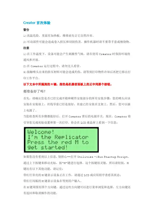
你会在LCD液晶屏上看到一下信息:如果您没有看到以上信息,别担心——打开Utilities ->Run Startup Script。
通过上下按键来移动光标,按“M”键进行选择。
这个按键很灵敏,所以请轻按。
M键还有以下其他功能,请记住:带红灯常亮的M键表示设备正在工作,请通过LCD或应用程序查看其状态;带红灯闪烁的M键表示设备在等到用户输入。
在M键周围有四个方向键,通过这些方向键可以进行菜单浏览和选择,左方向键还有返回和取消操作的功能。
首先,启动程序脚本会教给您关于Creator如何工作的基本介绍。
然后,它会教你如何调平打印平台,装载丝材,并开始一个打印测试。
第一次操作,请依据屏幕上的指令设置您的Creator!如果设备出现和本指南描述不符的故障或情况,请查看故障排除。
调平您的打印平台注意:调平打印平台对作品的打印质量非常关键!以下是第一屏信息:最后的省略号表示信息未显示完。
如果您已经阅读完要继续,请按闪烁的M键。
然后,你会看到:阅读完这个信息后,Creator会让您拧紧打印平台底部的旋钮。
K13D Printer User ManualV1.0Thank you for choosing our products. For the best experience, please read this User Manual carefully and strictly follow the instructions to operate the printer. Ourteams will always be ready to provide you with the best services. Please contact us via the phone number or e-mail address provided at the end of this User Manual when you encounter any problem with the printer. For a better experience in using our products, you can also learn how to use the printer in the following ways:Accompanied instructions: you can find the relevant instructions and videos in the USB flash disk.You can also visit our official website (https://) to find information regarding software, hardware, contact information, device instructions, device warranty information, and more.1. About the Device 1.1 About the Printer 1.2 Device Specifications 1.3 Packing List2. Unboxing 2.1 Unpacking Steps 2.2 Install the Product 2.3 Power-on guide3. About the User Interface 3.1 Main、Prepare 3.2 Files 3.3 Tune、Support4. First Printing 4.1 USB flash disk Printing 4.2 LAN Printing5. Functional Specification 5.1 Extrude、Filament Retreat6. Tips and Routine Maintenance 6.1 Maintenance Items 6.2 Error Code Instructions 6.3 Precautions for printing ...................................................................................................................................................................................................................................................................................................................................................................................................................................................................................................................................................................................................................................................................................................................................................................................................................................................................................................................................................................................................................................................................................................................................................................................................................................................................................................................................................................................................................................................................................................................................................................................................................................................................................................................................................................................................................................................................................................................................................................................................................................................................................................................................................................................................................................................................................................................................................................................................................................................................................................................................................................................................................................................................................................................................................................................................................................................................................................................................................................................................................................................................................................................................................................................................................................................................................................................................................................................................................................................................................................................................................................................................................................................................................................................................................................................................................................................................................................................................................................................................................................................................................................................................................................................................................................................................................................................................................................................................................................................................................................................................................................................................................................................................................................................................................................................................................................................................................................................................................................................................................................................................................................................................................................................................................................................................................................................................................................................................................................................................................................................................................................................................................................................................................................................01-0301-0102-0203-0309-0911-1112-1216-1617-1718-1819-2017-2013-1509-1110-1012-1516-1604-0804-0506-0708-081.1 About the Printer1.3 Packing ListWrench and Screwdriver ×14Touch screen 2Filament3Blade ×15M6 socketspanner ×112After-sales ServicesCard ×115Power Cable ×111Material barrel ×161.2mm nozzle cleaner ×1813Tool Box ListCutting plier ×17USB flash disk ×19LubricatingGrease ×1Quick Guide ×1* Tips: the above accessories are for reference only. Please refer to the physical accessories!2.1 Unpacking StepsKeep the blue cube in the figure clean of debris and then click "OK".① Network Settings② Time Zone Settings③ Creality Cloud binding④ Self-inspection⑤Self-testing2.3 Power-on guide⑥ Self-test completedNote: The current interface is for reference only. Due to the continuous upgrading of functions, it shall be subject to the latest firmware UI published on the official website.Prepare3.1 Tune、Prepare① Local model② Press and hold on the model to multi-selectand copy it to a USB flash drive③ USB flash drive model ④ HistoryTips: Choosing print calibration can improve print quality 3.2 FilesNote: The current interface is for reference only. Due to the continuous upgrading of functions, it shall be subject to the latest firmware UI published on the official website.SupportSystemSystem HelpNetworkError historyUpload LogNote: The current interface is for reference only. Due to the continuous upgrading of functions, it shall be subject to the latest firmware UI published on the official website.4.1 USB flash disk Printing④ Printing③ Select to print② USB flash drive modelNote: The current interface is for reference only. Due to the continuous② Choose a language and region;③ Choose a Printer;⑤ Select to download the model;④ Click on "Model Library" and select the model file;4.2 LAN Printing Creality Print①Download at()or find the software on a USB flash driveand install it.Note: The current interface is for reference only. Due to the continuous upgrading of functions,it shall be subject to the latest firmware UI published on the official website.4.2 LAN Printing⑥ Log into a Creality Cloud account;⑦Start slicing;⑧Selection of LAN printing;⑩ Device List;Add a device: a. Add by scanning;→Select a device;⑪ Device Details 。
3d打印机说明书睿之鲲ROC-2型3D打印机使用说明书适用机型:RZK-ROC-250型 RZK-ROC-300型适用前请仔细阅读本安装使用说明书请妥善保管本使用说明书,以备日后查阅。
图片仅供参考,产品以实物为准。
非常感谢您选择购买我公司3D打印机。
在安装使用该设备前,请您仔细阅读本使用说明书,该说明书介绍了本机的功能及特点以及维护等方面的内容,请您与购机发票一并保持,以备它用。
一、安全注意事项为确保使用安全,避免对您或他人造成伤害和财产损失,请您务必遵守以下安全注意事项。
不遵守安全警告而错误使用时可能导致事故发生。
本产品未考虑以下情况:无人照看的幼儿和残疾人对设备的使用及幼儿玩耍设备的情况。
1.1禁止的内容1.1.1请勿让儿童单独操作使用,并确定不会将产品当成玩具,设备要放置在婴儿接触不到的地方。
老年人或残障人士以及无使用经验的人应该在监护和指导下使用本产品。
1.1.2本产品工作时禁止移动或碰触正在运行中的部件,避免意外伤害。
1.1.3禁止将电源线挂于锋利的物体上,且不能连接到可移动的物体。
1.1.4禁止在倾斜的台面或不稳定的台面使用本产品。
1.2强制内容1.2.1插头或其他零件损坏时,必须停止使用本产品,并及时和厂家取得联系,请专业人士更换或维修,以免引起伤害。
1.2.2在拆装或调试产品的部件前,请确保产品出于断电状态。
1.3可能造成人身伤害的事项1.3.1电源线损坏,为了避免危险必须由厂家或类似部门的专业人员更换。
1.3.2请勿使用本产品以外的附件和配件,以免引起火灾或人身伤害。
1.4可能造成财产损失的事项1.4.1使用本产品前请确认电压是否和本产品默认规格一致(220V-50HZ),以免发生安全危险和损坏。
如客户使用110v电压,需调整机器底部开关电源的选择档。
1.4.2本产品开机超过十分钟不能按照指令加热或启动请联系厂家,请勿擅自拆机。
1.4.3若产品在运行过程中出现卡死现象,请立即关掉电源并与厂家售后保持联系。
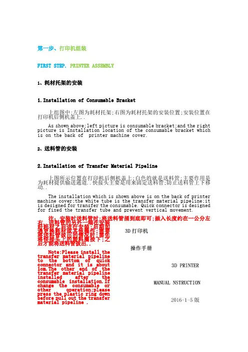
第一步、打印机组装FIRST STEP. PRINTER ASSEMBLY1、耗材托架的安装1.Installation of Consumable Bracket上组图中;左图为耗材托架;右图为耗材托架的安装位置;安装位置在打印机后侧机盖上..As shown above;left picture is consumable bracket;and the right picture is Installation location of the consumable bracket which is on the back of printer machine cover.2、送料管的安装2.Installation of Transfer Material Pipeline上图所示位置在打印机后侧机盖上;白色的就是送料管;主要作用是为耗材提供输送通道..快接头主要是用来固定送料管;防止送料管上下移动..The installation which is shown above is on the back of printer machine cover;the white tube is the transfer material pipeline;it is designed for transfer the consumable. Quick connector is designed for fixed the transfer tube and prevent vertical movement.注:安装时送料管时;将送料管捅到底即可;插入长度约在一公分左右..送料管的另外一端在安装好耗材之后进行安装;后期如遇更换耗材或其他操作;需要将送料管拔出的情况时;需先将快接头上的塑料圈按下;之后才能将送料管拔出..Note:Please install thetransfer material pipelineto the bottom of quickconnector and it is about1cm.The other end of thetransfer material pipelineinstalled after theconsumable installation.Ifchange the consumable orother operation;pleasepress the plastic ring downbefore pull out the transfermaterial pipeline .第二步、打印机平台调平SECOND STEP.ADJUST PRINTER OPTICAL FLATNESS说明:打印机平台调平一次之后;一般情况下不用重复调平..不过在运输过程中因为颠簸抖动;可能会导致平台的平整度发生变化;所以在使用之前建议先进行检查调平操作..Instruction:Usually you do not need to adjust the optical flatness after first adjustment.we recommend to check the status caused by transportation.1、调平前准备1.Adjustment Ready.首先检查喷嘴;保证喷嘴外表面洁净;没有赘余的耗材等物..如下图左所示;喷嘴处的赘余物可以用剪钳等工具剔除掉..达到如下图右所示即可..First checking the nozzle and make sure it’s clean on the surface.As shown belowLeft;Use pliers and other tools to weed out the remainder.as shown belowRight.2、控制打印机辅助调平2.Printer Assist Adjust Level Control首先需要为3D打印机通电;3D打印机所使用的是普通220V家用电;直接接入即可..该款3D打印机屏幕为触控屏幕;下图左为主界面;点击“工具”;选择“调平”如下图右..Power ups the 3D printer first;3D printer use home voltage 220V.This 3D printer is touch screen model;The main menu as shown belowLeft;Click the “TOOLS”;selecte“ADJUST MENT”as shown below Right.随后会出现如下图左所示界面;点击“NEXT”;当喷头每次移动到一个微调螺母上方时;进行平台的微调;微调螺母如下图右所示..Then click “NEXT”as shown below Left;Adjust the platform when the nozzle move to the location above the fine adjustment nut.as shown belowRight.平台上共分布着三个微调螺母;随着“NEXT”的点击;喷头会依次移动到微调螺母上方;每个点调节到如下图所示距离即可;或者可以将一张A4纸对折后;放在喷头和平台之间;调节时;适当抽拉纸张;纸张刚好可以轻松的抽出来的时候;说明喷头和平台的距离基本合适了..也可以以玻璃平台上喷头的倒影和喷头实体之间的距离作为参照进行调节..There distribute 3 fine adjust nuts;the nozzle will move above the nuts in turns;Adjust each of the regulatory point as shown below;Or fold a piece of A4 paper and place it between nozzle and platform.if you can draw out the paper gently;itproves the nozzle fit the basic platform.You can also Adjust it by the reflection on the glass platform sprinklers and nozzles entities as a reference.注:微调螺母的原理:微调机构由螺丝、蝶形螺母、弹簧三部分组成..当螺母拧紧的时候;平台便会向下方移动;从而拉远喷头和平台的间距;当螺母拧松的时候;由于弹簧的弹性作用;便会将平台向上方顶起;从而拉近喷头和平台的间距;Note:Theory of fine adjustment nuts:Fine adjustment mechanism by screws; wing nuts; springs.Screwing the nuts;the platform will move down;it will pull away the distance between nozzle and platform.Loosening the nuts;the platform will move up;caused by spring action;it will shrink nearly the distance between nozzle and platform;第三步、耗材的安装及岀丝测试THIRD STEP.CONSUMABLES INSTALLATION AND TESTING EXTRUDER1、喷头加热1.HEATING NOZZLE通过打印机显示屏控制喷头加热;如下图左所示点击“预热”;随后出现如下图右所示界面..Control heating nozzle by printer screen;Click the “Pre-Heating”as shown belowLeft;it will display the follow interface;as shown belowRight.如上图右所示..第一行为平台的温度控制选项;数字表示平台的“当前实际温度/设置温度”;第二行为喷头的温度控制选项;数字表示喷头的“当前实际温度/设置温度”;其中向上向下的箭头;分别表示提升降低温度..现在需要将平台的“设置温度”设置到64度;将喷头的“设置温度”设置到205度..如下图所示..As shown aboveRight.The first line are the platform temperature control options;the numbers shown on the screen are“TEMP/TEMP SETTING”;The second line are the platform temperature control options;the numbers shown on the screen are “TEMP/TEMP SETTING”;The UP and DOWN arrows stands for lifting and lowering the temperature.Set the platform temperature to 64℃;then set the nozzle temperature to 205 ℃..As shown below.2、耗材的处理2.Dealing with Consumables将耗材从包装盒内取出后;将耗材的端部用剪钳剪出一个斜口;以便于耗材的送入..另外耗材的端部约五公分的长度需略微的握直;也是便于耗材的送入..如下图所示..Taking the consumables out of the packaging box;and For insert easily ;cut out an incline on one side and straight grip around 5cm from the end of the other side.as shown below;将耗材挂在耗材托架上;然后将耗材从打印机后侧机盖的快接头下方送入如下图左所示..耗材从送料卡下方送入;然后用手将送料卡捏住;如下图右所示..之后将耗材继续向内穿入;直至从送料管的另外一端穿出..Hang up the consumables on the bracket;then insert it to quick connector on the back of the printer. Insert the consumables across the back of transportation card;Pinch the transportation card;as shown belowRight.Insert the consumable until itpenetrate from the other side of the transportation pipeline.耗材从从送料管另外一端穿出后;将耗材从喷头上方的快接头处穿入;如下图左所示..随后即可将送料管插入快接头固定;插入长度约在五公分左右..如下图右所示..Insert the consumable from the quick connector on the top of the nozzle;after penetrate the transportation pipeline form the other side of the consumables .as shown belowLeft.Then fixed the transportation pipeline after insert the quick connector;The insert length is about 5 cm.as shown belowRight.注:后期如遇更换耗材等操作;需要将送料管拔出的情况时;需先将快接头上的塑料圈按下;之后才能将送料管拔出..Note:If change the consumable or other operation;please press the plastic ring down before pull out the transfer material pipeline .3、测试岀丝3.Testing Exturder通过打印机显示屏控制挤出机的转动;也就是控制E轴转动..如下图左所示;图中“10 1 0.1”表示电机单次转动的距离..单位为毫米;建议测试岀丝的时候选择10或1..选好后按击“E↓“;之后会发现喷嘴处会有耗材挤出;如下图右所示..Control the turn of extrusion machine by printer screen;That is control E axis turn rate.as shown belowLeft;as shown ‘10mm’’1mm’’0.1mm’it stands for motor rotation distance for each time.the unit is mm.We recommend select 10mm or 1mm for testing extruder.Click‘E↓’after selection;as shown belowRight;it will appear some consumable from nozzle.直至挤出的耗材顺滑均匀即可..至此耗材的安装及岀丝测试结束..下面进行模型的打印..Until the consumable comes out smoothly and uniform from the extruder.Thus we finish the consumables installation and extruder testing.The following step is print model.第四步、模型的打印1、打印前准备1.Preparation Before Printing将所要打印的模型导入“切片软件”中;进行打印参数设置;之后导出打印机可以识别的“Gcode”文件;“切片软件”的操作参考“切片软件操作教程”;这里仅给出该款3D打印机适用的参数设置..Insert the model print ready to‘Slicing software’;Export the ‘Gcode’file after set up the print parameters;For How to use "Slicing software;" please reference the section of the software operation tutorial".Below is the 3D printer macine settings parameters.将导出的“Gcode”文件拷贝入SD卡;然后将SD卡插在打印机上如下图所示..Copy the exported file‘Gcode’to SD card;and insert it to Printer;as shown below.之后用打印机箱内配备的胶棒;如下图左所示;在平台上所要打印模型的区域进行涂抹;如下图右所示..Daub the printing area with equipped glue stick;as shown below.2、打印模型2. Print Model在打印机屏幕上;选择“打印”如下图左所示;如下图右所示;选择要打印的模型文件后;如下图下所示;点击中间的按钮;打印机便会开始按照文件内的指令自主进行打印..Select’PRINT’from the printer screen; as shown belowLEFT;As shown belowRIGHT;After selected the printing file;As shown belowDOWN;Click the middle button;the printer will Auto-Start printing according the instruction of the printing file;3、打印完成后的处理3pleted Processing打印完成后;用配备的平铲将模型从平台上铲下即可;如下图所示..After printing is complete; Shovel the model down from the platform with equipped flat shovel; as shown below.注:建议每次打印前都先进行喷头的加热及岀丝测试;保证打印机耗材输送正常;保证打印的模型的质量..Note:As to ensure the transportation of printer consumables in normal work and make sure the quality of printing model;we strongly recommend heating nozzle and testing extruder before each item.。
V12 Dec 153D PrintPRO 2USER MANUALContents01 02 Overview of your Extraction system (front) Overview of your Extraction system (back) 1 01 Unpacking and unit placement 3 01 02 Connecting to power supply Optional Added Features 4 01 Turning extractor On 5 01 02Important safety notes Safety labels2 01 02 Cleaning the unit Filter replacement6 013D Print Pro 2 Specifications801 Consumable Spares & Filter Disposal 7OverviewLidClipsAir Inlet011Company BrandingFilter ConditionLightFeetOverviewFuse CompartmentAir Outlet/Motor Cooling021Main IsolationSwitchMains InletFuse RatingSafety InstructionsImportant safety notesConcerning symbols used on the extraction unit and referred to within this manual.DangerRefers to an immediately impending danger. If the danger is not avoided, it could result in death or severe (crippling) injury. Please consult the manual when this symbol is displayed.WarningRefers to a possibly dangerous situation. If not avoided it could result in death or severe injury. Please consult the manual when this symbol is displayed.CautionRefers to a possibly harmful situation. If not avoided,damage could be caused to the product or something in its environment.Important (Refer to manual)Refers to handling tip and other particularly usefulinformation. This does not signify a dangerous or harmful situation. Refer to manual when this symbol is displayed.Electrical SafetyThe 3D Print Pro 2 has been designed to meet the safety requirements of the Low Voltage Directive 2006/95/EC (previously numbered 73/23/EEC)WarningWhen working with the pump/motor housing open, Live 230/115 volt mains components are accessible. Ensure that the rules and regulations for work on live components are always observed.ImportantTo reduce the risk of fire, electric shock or injury:1. Always isolate the system from the mains powersupply before removing the pump/motor access panel.2. Use only as described in this manual.3. Connect the system to a properly grounded outlet.Dangers to eyes, breathing and skinOnce used, the filter within the 3D Print Pro system may contain a mixture of particulates, some of which may be sub-micron size. When the used filters are moved it may agitate some of this particulate, which could get into the breathing zone and eyes of the operative. Additionally, depending on the materials being used, the particulate may be an irritant to the skin.This unit should not be used on processes with sparks of flammable materials or with explosive dusts and gases, without implementation of additional precautions.Caution: When changing used filters always wear a mask, safety shoes, goggles and gloves.Carbon selectionPlease note that the media within the filter fitted in the 3D Print Pro 2 is capable of adsorbing a wide range of organic compounds. However, it is the responsibility of the user to ensure it is suitable for the particular application it is being used on.BOFA Technical ServiceIf problems arises with your 3D Print Pro unit please contact us: • •Mon-Fri, 9am-5pm.Email:*****************.ukSerial NumberFor future reference, fill in your system details in the space provided. The serial number is on the rating label located on the side/rear of the unit. Serial Number:012Safety InstructionsWarning and Information labelsThe following listing details labels used on your 3D Print Pro extraction unit.Goggles, Gloves & Mask LabelLocation: Front face of filter.Meaning: Goggles, Gloves and Masks should be worn while handling used filters.Do Not Cover LabelLocation: Bottom panel.Meaning: Do not cover any louvers or holes adjacent to the label.Electrical DangerLocation: Bottom PanelMeaning: Removal of panels with this label attached will allow access to potentially live components.Warning LabelLocation: Next to release clips.Meaning: Power should be isolated before the panel with this label attached is opened/ removed.Serial Number LabelLocation: Next to mains inlet.Meaning: This label contains a variety of information about the extraction unit, including.• Company name, Address & Contact number • Extractor model • Unit serial number• Operating voltage range • Maximum current load • Operating frequency • Year of Manufacture• Relevant approval markings/ logosPLEASE NOTE: If the equipment is used in a manner not specified by the manufacturer, the protection provided by the equipment maybe compromised. Fire Risk WarningIn the very rare event that a burning ember or spark isdrawn into the fume extraction unit, it may be possible that the filters will ignite.Whilst any resultant fire would typically be retained within the fume extraction unit, the damage to the extractor could be significant. It is therefore essential to minimise the possibility of this occurring by undertaking an appropriate Risk assessment to determine:-a). Whether additional fire protection equipment should be installed.b). Appropriate maintenance procedures to prevent the risk of build-up of debris which could potentially combust.This unit should not be used on processes where sparks could occur, with explosive dusts and gases, or withparticulates which can be pyrophoric (can spontaneously ignite), without implementation of additional precautions It is essential that nozzles or other extraction/ fume capture devices and hoses/pipework are cleaned regularly to prevent the build-up of potentially ignitable debris022Before InstallationPackaging Removal & Unit PlacementBefore installation, check the extraction unit for damage. All packaging must be removed before the unit is connected to the power supply.Please read all instructions in this manual before using this extractor.1. Move the unit to the location where it is going to beinstalled and remove the outer packaging. This unit should be installed in a well-ventilated area.Ensure that 500 mm space is available around any vented panels on the extractor to ensure adequate airflow.2. Check the filter is located in its correct position before replacing the lid and securing the clipsCautionDo not block or cover the airflow and motor cooling ports on the unit, as this severely restricts airflow and may cause damage to the unit.CautionUnder no circumstances should the exhaust outlet/s be covered as this will restrict the airflow and cause overheating.013InstallationSpecification: 3D Print Pro 2Dimensions: Height 338mm Depth 270mm Width 283mm Weight: 8.2kg Voltage: 115-230V Frequency: 50/60Hz Full load current: 0.2A Power: 6.6W Capacity: 43 m³hConnection to Power SupplyPlease follow the above specification when selecting the power supply outlet for the extraction system, ensure the power supply is suitable before connecting the 3D Print Pro system.Check the Integrity of the electrical power cable, if the supply cord is damaged the extraction unit should not be connected to the mains. The supply cord should only be replaced by a BOFA engineer as an electrical safety test may be required after replacement.The extraction unit MUST be connected to a properly earthed outlet.If your extraction system was ordered with any optional extras please read section 4.02 beforethe power connection is made as additional connections may be required before power is connected to the extractor.Connect the power cable to an isolated electrical supply.The mains socket should be installed near the extractor it should be easily accessible and able to be switched On/ Off. The cable run should be arranged so as not to create a trip hazard.Pairing with the 3D printer SystemThe 3D PrintPRO 3 has been specially designed to be used alongside a wide spectrum of middle range 3D printers available on the market.Fume can be captured in a number of ways including nozzles and funnels.The extraction point needs to be as close as possible to the printing area without interfering with the 3D printing process to ensure effective fume extraction.014InstallationOptional added featuresRemote Stop/Start featureEnables the extraction unit to be remotely turned On / Off via an external signal.Note: Care must be taken to ensure that the system is correctly wired in order for the extraction unit to function correctly.DC Voltage inputThis configuration requires the Black & Red cores of the signal cable (Refer to section 1 for location) to be connected to a known and tested DC power supply, in order to start the extractor.The operating voltage for this signal is 24VDC. Only this voltage should be connected. Voltages connected outside of this range may cause irreversible damage to the relay. Red cable = V+ Black cable = V-When the extractor is provided with the correct DC voltage the motor will start. When the DC voltage is removed the motor will slow down and come to a stop.The extractor will need to be turned on (See section 5 for turning the extractor on) in order for this feature to operate.024OperationTurning extraction unit OnThe 3D Print Pro 2 features a fused IEC inlet for the mains cable as well as a main isolation switch. The unit can be powered on and off by pressing the red rocker switch to the right hand side.Main Isolation SwitchMains InletFuse Compartment01 5MaintenanceMaintenance UKIt is a legal requirement, under regulation 9 of the COSHH regulations that all local exhaust ventilation systems are thoroughly examined and tested at least once every 14 months (typically carried out annually). The approved code of practice recommends that a visual check should be carried out at least once a week.COSHH requires the annual inspection and testing to be carried out by a competent person and specifies that documentation results are recorded in a log.Contact the seller for more information about inspection and certification.Maintenance GeneralUser maintenance is limited to cleaning the unit and filter replacement, only the manufacturers trained maintenance technicians are authorised to carry out component testing and replacement. Unauthorised work or the use of unauthorised replacement filters may result in a potentially dangerous situation and/or damage to the extractor unit and will invalidate the manufacturer’s warranty.Cleaning the unitThe powder coat finish can be cleaned with a damp cloth and non-aggressive detergent, do not use an abrasive cleaning product as this will damage the finish.The cooling inlets and outlets should be cleaned once a year to prevent build-up of dust and overheating of the unit.Filter InformationA log of filter changes should be maintained by the user. The filters require attention when the display shows the configuration shown on the next page or when the extractor no longer removes fume efficiently.It is recommended that a spare set of filters are kept on site to avoid prolonged unit unavailability. Part numbers for replacement filters can be found on the filters fitted in your system.To prevent overheating, units should not be run with a blocked filter condition, or with dust obstruction of Inlets / Outlets.Fire Risk WarningIn the very rare event that a burning ember or spark is drawn into the fume extraction unit, it may be possible that the filters will ignite.Whilst any resultant fire would typically be retained within the fume extraction unit, the damage to the extractor could be significant.It is therefore essential to minimise the possibility of this occurring by undertaking an appropriate Risk assessment to determine:-a). Whether additional fire protection equipment should be installed.b). Appropriate maintenance procedures to prevent the risk of build-up of debris which could potentially combust.This unit should not be used on processes where sparks could occur, with explosive dusts and gases, or with particulates which can be pyrophoric (can spontaneously ignite), without implementation of additional precautionsIt is essential that nozzles or other extraction/ fume capture devices and hoses/pipework are cleaned regularly to prevent the build-up of potentially ignitable debris01 6MaintenanceFilter ReplacementThe 3D Print Pro 2 will alert the user when its filter needs tobe replaced. When the filter becomes full the red ‘FilterCondition light will glow.To remove and replace the pre filter follow the proceduredetailed below.1.Isolate the electrical supply to the extractor2.Undo the clips on the sides of the unit and removethe lid.3.Lift the pre filter pad out of the top of thecombined filter. Replace with a new pad.4.Replace the lid and secure the clips.To remove and replace the combined filter follow theprocedure detailed below.1.Isolate the electrical supply to the extractor2.Undo the clips on the sides of the unit and removethe lid.3.Lift the filter out of the unit and remove the prefilter pad from the top. Once removed it isrecommend that the used filters are bagged andsealed.4.Lower the new filter into position and replace thepre filter pad.5.Replace the lid and fasten the clips.Note: The filter MUST be fitted when the extractor is inuse.026Replacement PartsConsumable SparesThe 3D Print Pro 2 contains a combined filter. These shouldbe replaced when instructed to do so by the 3D Print Proextraction system (see section 6 for replacing the filters)To maintain performance it is important that the filters arereplaced with identical BOFA filters. To re-order please referto the Filter number printed on the filter installed in yourextraction unit.Maintenance ProtocolUsers can record changes in filter change intervals on thetable below.Filter disposalThe combined filter is manufactured from non-toxicmaterials. Filters are not re-usable, cleaning used filters isnot recommended. The method of disposal of the usedfilters depends on the material deposited on them.For your guidance017System SpecificationsUnit: 3D Print Pro 2Capacity: 43 m³h Weight: 8.2kg Motor: Axial Fan Output: 6.6WElectrical supply: 115-230V Hertz: 50/60HzFull Load Current: 0.2A Noise Level: Below 50 dBA (at typical operating speed)Environmental operating range:Temperature: +5o C to + 40o CHumidity: Max 80% RH up to 31o C Max 50% RH at 40o C018Contact Information BOFA Headquarters19-20 Balena Close Creekmoor industrial Estate PooleDorsetBH17 7DUUKPhone: +44 (0) 1202 699 444 BOFA Americas303 S.Madison Street StauntonIllnois62088USAPhone: +1 (618) 205 5007 BOFA International GmbH Sudring 62D-21465Wentorf bei Hamburg GermanyPhone: +49 (0) 40 7393735-15。
目录第一部分Easy3DP-II系统简介 (3)1.1 Easy3DP-II系统组成及性能参数 (3)1.2 Easy3DP-II系统防护及安全 (4)1.3 Easy3DP-II系统开机操作 (7)第二部分制作成形件 (8)2.1图形预处理 (8)2.2零件制作 (8)2.3 零件的后处理 (9)2.4 Easy3DP-II系统操作的整个工艺流程 (12)2.5 用于HB1快速成型材料推荐的参数设置 (12)第三部分软件界面 (14)3.1 菜单项 (14)3.2 可选择的3D投影方式及显示方式 (15)3.3 实体变换及制造设置 (16)3.4 制造: (17)3.5 工具栏 (20)3.6 状态栏 (20)第四部分常见故障及处理 (21)第五部分设备维护与保养 (23)5.1 整机的保养 (23)5.2 工作缸的保养及维护 (24)5.3 Z轴丝杆、铺粉辊导轨的保养及维护 (29)第七部分系统软件的安装 (30)7.1 利用ghost恢复系统: (31)7.2 重新安装系统 (26)第八部分系统验收清单 (33)为确保Easy3DP-II型全彩打印机正常工作,请用户在使用前仔细阅读本操作手册。
第一部分Easy3DP-II型全彩打印机简介1.1Easy3DP-II型全彩打印机组成及性能参数1.1.1基本组成Easy3DP-II 型全彩打印机由三部分组成:计算机控制系统、主机、液晶显示器(自选),如图1.1所示。
图1.1 Easy3DP-II型全彩打印机1. 计算机控制系统该计算机控制系统由高可靠性计算机、精准的各种控制模块、电机驱动单元、各种传感器组成,并配以自主研发的Easy3DP V1.0软件,该软件可实现三维图形数据处理,加工过程的实时控制及模拟等功能。
2.主机该主机由六个基本单元组成:工作缸、储粉缸升降装置,落粉桶,铺粉辊装置、机架与机壳,它们主要完成系统的加工及传动功能。
1.1.2 Easy3DP-II型全彩打印机性能参数(尺寸可定制)1.2 Easy3DP-II型全彩打印机的防护及使用安全1.2.1 Easy3DP-II型全彩打印机对环境的要求1. 环境温度要求:22℃左右,需要根据空间大小配置适当功率的空调。

TUMI RAISE BORING使用 SOLIDWORKS 进行机器设计,缩短产品上市时间,提高竞争优势挑战:简化高性能机器的开发流程,并应用持续的创新满足客户需求,提供独特的体验。
解决方案:针对项目实施 SOLIDWORKS Professional™,针对技术文档使用 SOLIDWORKS Composer™。
成效:• 设计周期缩短 40%• 材料明细表创建时间缩短 50%• 2D 文档错误减少 20%• 定位零件和设计的速度提高 30%• 提高对工程设计的理解• 人为错误减少 70%TUMI 公司由 Stu Blattner 于 1998 年在秘鲁利马市成立,拥有 20 多年的钻井经验,钻探总计超过 10 万米。
目前,他们的机器分布在全球各地,如阿根廷、澳大利亚、巴西、加拿大、美国、印度尼西亚、意大利、墨西哥和南非等国家/地区。
他们与 Stu Blattner Inc. 达成战略联盟,在全球天井钻进行业具有较强的竞争力。
在决定采用 SOLIDWORKS®作为开发 3D 设计的平台之前,TUMI 在项目开发阶段使用 AutoCAD®等 2D 工具,仅在特殊情况下和其他用途时创建 3D 设计,如干扰检测、创建 2D 视图和渲染。
TUMI 工程公司一直致力于不断努力提高其产品质量和流程效率。
然而,仅使用 AutoCAD 这样功能有限的工具在 2D 中创建项目很难达到预期目标。
除此之外,他们还不断为设计周期延迟、材料明细表不可靠、高返工率、设计修改、制造过程2D 文档理解困难、装配问题等问题而烦恼不已。
为了消除这些限制,不断提高其项目质量,增强市场竞争力,TUMI 决定实施 SOLIDWORKS 进行项目开发。
他们收到了立竿见影的效果,在使用 SOLIDWORKS 完成的第一个项目中,设计周期缩短了 40%。
据项目工程师 Jorge Arizaca 介绍,使用 SOLIDWORKS 让他们能够快速做出决策,并且包括在生产组中达到 TUMI 的工作标准。
3D打印机新手操作手册编写日期:执行日期:目录开箱指南和硬件安装 (2)(一)警告 (3)(二)注意 (3)(三)装箱清单 (3)开箱指南 (3)初始硬件安装 (5)软件的安装 (6)O:空走速度一般为70-30选择 (6)F:喷头温度为220度 (6)连接机器以及如何给喷头及底板加温 (7)进丝与退丝 (9)如何载丝 (10)退丝 (11)开箱指南和硬件安装我们出厂时非常仔细的对Creator或者CreatorII进行打包装箱——我们希望您能在仔细阅读本指南后,再仔细开箱。
请您应该始终如一的小心爱护和使用Creator。
Creator对静电比较敏感,请确保你在操作Creator和尝试任何校正前,先通过接触接地物体把身体上的静电释放掉。
在您自行打开Creator进行维修时,请保证电源已经关闭,电线连接已经断开。
(一)警告1)高温危险。
里面有加热板,维修前先让它自然冷却。
2)可动部件可能会造成卷入挤压和切割伤害。
操作机器时请不要带手套或缠绕物。
(二)注意1)在工作温度下,设备可能会产生刺激性气味,请在使用Creator时保持环境的通风和开放。
2)在Creator运行过程中,请勿无人看管。
3)接触喷头出来的挤压材料可能会造成灼伤,请等到打印物件冷却后再把它移出打印工作平台。
(三)装箱清单——Creator系列机器在Creator机器顶部的纸盒是配件箱,里面有:——一个或两个喷头——1X或2x 丝盘支架——螺栓工具盒——六角扳手工具盒在Creator机架里的工作平台下面:——1kg 原色ABS丝盘——1kg 黑色ABS丝盘(仅配套双喷头机型)在Creator机器下面:——电源线——USB A to B 电缆——1x 或2x 丝线导套开箱指南Creator打印机出厂时经过非常紧凑而仔细的包装,请花点时间仔细拆箱。
在本部分内容中,机器的重要部件名称将会用粗体表示。
注意:不要强行撕开任何东西——你有可能会损坏Creator。
3D打印操作手册1.0版一、原始数据处理通过邮箱收取客户需要打印的数据,数据下载存放于Magics电脑的F盘-xiazai-wuxishuju/CQSHUJU,数据文件夹以日期+批次命名。
例:2017050901/2017050901cq 对同一批次的数据进行改名编号,公司名开头字母缩写+编号。
例:第一批数据包含成都琢美1个文件、无锡雅冠2个文件、上海航轩3个文件,该批次的文件改名后数据名为:cdzm001、wxyg002、wxyg003、shhx004、shhx005、shhx006二、加支撑处理1、完成改名的数据放入工作优盘-数据-对应年月文件夹,转移到3Shape电脑进行加支撑处理,数据存放于E盘-3dentaldata-STL(1)-对应年月文件夹。
2、使用3Shape软件对数据进行加支撑处理新建工作平台选择一个默认数据类型(一般选该批次数据占多数的类型)重庆分点数据类型默认使用chongqing0425类型,导入数据后不需要更改数据类型选好类型后点添加新平台中添加数据选中需要加支撑的数据检查每个数据修改正确的类型(重庆分点统一类型可跳过这个步骤)同批数据中最多数量的数据不加标签,其他数据都要加上标签以便区分完成类型修改后进行自动放置(Place)系统自动排位后可点放置进行手动修改数据摆放位置手动拖动旋转数据来进行位置摆放(左键平移,右键旋转),EOS机器数据尽量自左往右排放。
排放好的数据确定后,选中第一个数据,点检查进行支撑检查进入检查界面选支撑选项支撑超过半牙的都删除(边缘有倒凹情况的除外)支撑稀疏的地方可以手动添加支撑(特别注意最低点)前牙底部较为单薄,最低点前后各加一排支撑挨个检查完毕,点确定点制备开始生成支撑文件生成支撑文件完毕,确定3、操作加支撑处理的人员将总览图片(overview),图片在文件夹E盘-3dentaldata-SLI(2)-M100_30_m_年_月_日_时_分-overview,存放至E盘-3dentaldata-排版总览图片中,以便后续查询及统计。
3D打印机用户使用简明手册武汉斯托得科技有限责任公司一、安全注意事项◆安装规范使用电源●请使用本机附带的电源适配器,使用220V电源。
●请勿在手湿时拔电源插头,或接触本机内导线。
●请勿拉拽、过度扭曲本机所配电线,以防造成断路或短路。
◆在打印过程中注意●请勿在没有人员监督的情况下使用本机。
●打印过程中和刚打印完成的时候,避免碰撞打印机内部的结构和打印件,以免烫伤。
●如果打印时发生打印机冒烟,产生异常噪音时,请立即关闭电源开关,停止打印机工作。
◆常做产品维护●定期在断电的情况下,用湿布拭去灰尘和粘接的打印材料。
●定期对打印机的传动件,如丝杆、轴承、丝杠添加润滑油,并清理积累的赃物。
二、产品介绍此产品是由武汉斯托得科技有限责任公司推出的第二代桌面式3D打印机。
它与普通二维打印机工作原理类似,区别在于二维打印机是使用油墨为打印材料,此3D打印机是使用融化状态的PLA或ABS为打印材料,通过电脑控制把打印材料一层层叠加起来就形成了实物,实现了将计算机中的灵感设计打印成现实世界中的实物。
它与传统制造方式不同的原理,及其理论上“无孔不入”的打印可能,留给人们巨大的想象空间。
它在短时间内为您实现任何您能想出的样品模型,及时保鲜您的创意火花。
在工程师们手里,它是制造大量的原型机母体,孕育着最终的投入大批量生产的成品;在家庭中,它简化了个性化的部件的制造方式,释放个体使用者的创新冲动;简易的使用方法更让孩子们爱上使用它,制造出自己的玩具,在娱乐中锻炼了智力和创新思维。
有了3D 打印机的帮助,您只需要能使用和学习一些软件操作即可将您的想法实现,改变了过去发明创造只是少数人的特权。
产品的原理主要基于堆积熔融FDM(Fused Deposition Modeling)工艺,即打印材料(PLA或ABS)经导管送向智能控制的喷头后,加热熔融并最终堆积成型。
成型的材料具高强度和高稳定性,能进行攻丝、钻孔、上色等操作,迅速参与使用。
POP 2 3D 扫描仪用户手册2022.8⚠本产品工作环境为0℃至40℃,根据电子元器件适用温度等级划分,不满足需要更高适应条件的军工级(-55℃至125℃)要求。
请在满足使用场景的环境下合理使用该产品。
目录产品概况 (3)产品介绍 (3)产品规格 (4)装箱清单 (5)硬件连接 (6)电脑连接 (6)手机无线连接方式 (6)指示灯状态 (7)软件安装 (7)系统要求 (7)软件安装 (7)Revo Scan- 用户界面介绍 (8)1. 主面板 (8)2. 新建扫描 (9)3. 扫描界面 (10)4. 模型列表 (11)Revo Scan – 扫描流程 (12)确认设备已连接 (13)点击“新建扫描” 选择扫描精度、模式和纹理贴图 (14)确认扫描距离为“最佳” (14)调节RGB相机和深度相机的亮度 (14)开始或暂停扫描 (15)完成/重新扫描 (16)构网 (18)贴图 (19)导出 (19)扫描技巧 (21)跟踪丢失 (21)点云较少 (22)检测到平面 (22)回退/恢复 (23)继续扫描 (23)批量操作 (25)快捷键 (25)帮助中心 (27)联系我们 (27)COPYRIGHT ©2022 REVOPOINT 3D ALL RIGHTS RESERVED 2产品概况产品介绍POP 2 三维扫描仪结合手持式三维扫描仪和台式三维扫描仪功能,汇集了公司最新的科研成果。
采用自主研发的3D摄像头硬件和高速智能芯片,性能更高,扫描物体时能够直接输出高精度的点云数据。
POP 2三维扫描仪核心硬件采用双目微结构光原理,借助专有的微投影芯片,确保快速获取高精度(高达0.05mm)的3D点云数据。
支持彩色扫描,直接生成栩栩如生的三维模型进行彩色3D打印。
智能算法上,POP 2内置高性能3D计算芯片,即使使用普通电脑扫描,也能有效保证扫描的流畅性。
3COPYRIGHT ©2022 REVOPOINT 3D ALL RIGHTS RESERVED产品规格产品名称3D 扫描仪产品型号POP 2采用技术双目红外结构光CPU Dual core ARM Cortex-A7单帧精度0.05 mm单帧扫描范围210 x 130 (mm)工作距离150 ~ 400 (mm)最小扫描尺寸20×20×20 (mm)帧率/扫描速度10 fps光源一级红外光拼接模式特征拼接,标记点拼接和色彩拼接是否有开关按钮有可输出格式PLY, OBJ, STL是否支持彩色扫描支持特殊物体扫描注意事项扫描透明物体,高反物体时,请使用扫描用显影剂。
Quick Start GuidePro2-Series 3D Printer* Please review this entire guide before operating the printer .Pro2Pro2 PlusThe contents of this Quick Start Guide may be updated over time. For the latest version, scan the QR code or visit the link below./pages/download#down-quickguidePro2-Series 3D Printer / Quick Start GuideA. List of PartsPro2Touch ScreenHot Ends FansZ-StagePrint Bed Filament Feeder Z Ball Screws Power InletPower Switch USB Storage Slots Pro2 PlusWheelsFilamentRun-out Sensor Camera HEPA Filter Filament Guide TubeTouch ScreenHot EndsFans Z-StagePrint Bed Filament Feeder FilamentRun-out Sensor Z Ball ScrewsPower InletPower SwitchUSB Storage SlotsCamera HEPA FilterFilament Guide TubeEthernet Interface Ethernet Interface01Pro2-Series 3D Printer / Quick Start GuideB. Hardware InstallationLocate the four shipping zip ties, and remove them.It's recommend to unclip these as opposed to cutting. They can be reused if you need to transport your machine in the future.13Remove!(×2)Hex Wrench(3 mm)Select the largest of the included hex head wrench (3mm), and remove all four hex head security bolts from Z-axis clamps (2 bolts each).These are located on the left and right sides on the printer on the ball screw thread.Peel the yellow sticker and remove the 24 security spacers.These clips are designed to hold theextruder assembly in place during shipping and should be saved for future transport. Do not operate printer with clips installed.2Remove!(×24)Remove!Plug the machine into a wall outlet using the power adapter for your designated country. (5 included)Flip the switch to power the unit on.402Pro2-Series 3D Printer / Quick Start GuideB. Hardware Installation (continued)Open the front door , and remove thestarter box and filament box from the base of the printer .Open these packages, and compare with the following contents list.7Once the unit has been powered, theprinter will go through a start-up sequence. Your Raise3D printer will take approximate-ly 60 seconds to boot up. When the touch screen displays the "Home" screen, the printer is ready.5Open the "Utilities" tab, and press the Z Homing button.OK the request, and the print bed will begin to “home” or move to the origin position.This will also allow you to access youraccessory packages.603Pro2-Series 3D Printer / Quick Start GuideSpatulaFilament(×2)Filament Holder(×2)Nozzle Cleaning KitTweezers USB Storage Other Accessories(Spare)Fuse 15A10AThumb Screws(Spare)Power Cable(×5)B. Hardware Installation (continued)Heat Resistant Gloves Build Plate(with Build Surface inside Protective Cover)List of ContentsHex Wrenches 2.521.5304Pro2-Series 3D Printer / Quick Start GuideB. Hardware Installation (continued)Lower the Z platform by 50mm.To do this, set the interval at "10mm" by selecting it in the "Move Steps" bar . This will move the bed 10mm per arrow click. Click this downward arrow 5 times to move Z platform downward to 50mm.8Remove the aluminum build plate from the foam packaging.10Protective FoamCoverBuild Plate Remove!Loose the two thumb screws on the Zplatform by rotating the two thumbscrews counter-clockwise.905Using the included spatula, remove the leveling calibration model from your build plate.11Pro2-Series3D Printer / Quick Start GuideB. Hardware Installation (continued)Re-install the thumb screws, rotating clockwise, to lock the build plate into position.Open the side door of the printer , and install the filament holders into themounting points. Open one of the included spools of filament, and place it on the holder .NOTE: The direction of filament spool should be placed to rotate in clockwise if at points B and D, and should be oriented to rotate counterclock-wise at mount points A and C.ABCD14Mount Points Slide the build plate onto the Z platform with the logos facing upwards, and the handle edge facing the front of the machine.121306Pro2-Series3D Printer / Quick Start Guide B.Hardware Installation (continued)Locate the open end of the filament, and15feed it through the guide tube.Press the “Utilities” tab on the screen and16set the temperature of the left nozzle forthe filament that you're using.Press the “Load” button and the printer willbegin to heat. When the target tempera-ture is reached, press "Load". Completethe feeding operation according to theinstructions on the screen.NOTE: This document's instructions are based onthe properties of Raise3D PLA filament. This isthe standard filament included with your productand it is advised to use the Raise3D PLA fortesting and initial setup.Pro2-Series 3D Printer/ Quick Start GuideC. ideaMaker InstallationOpen the installer and choose your preferred language. Select the installation location for ideaMaker , and click "Next".1The ideaMaker slicing software is available on the USB storage drive included with your printer .Additional downloads and versions are available online at: /pages/downloadDownload ideaMakerWINDOWS08Click "Finish" and ideaMaker is installed.Follow the instructions provided by the console, and click "Install". After the installation is finished, click "Next" to go to the next step.23Open the Disk Image for the ideaMaker installer. This is located in the USB storage drive included with your printer, or download the latest version from/pages/download#down-im.Drag the ideaMaker icon(left) into the Application folder on the right side.When launching ideaMaker for the first time you, you will need to select your printer 1model from the drop-down list, then press "Next".Select the diameter of your filament. Press "Finish" to finalize the initial settings.2NOTE: ALL Pro2-Series printers use 1.75mm filaments.Click the "Start" or “ ” button to begin slicing the model.2Click the "+" button to import “Giveaway Spinner” included in the USB storage.1Confirm your printer type and material are correct, then select the standard slicing template. Click “Edit” to select the type of Platform Addition and the type of Support.3Select your type of Platform Addition and Support in the "Edit" window. Click "Save 4and Close" to return to the previous menu. Click "Slice" to generate your file.Save the sliced files (.gcode and .data) by exporting to the USB storage drive.5NOTE: File names that do not conform to the Western Latin character set may not display properly.Confirm that the files are saved and eject the USB storage.6The Pro2/Pro2 Plus units are preleveled in the factory, but we recommend verifying that the leveling has not changed during shipping.First, home the X/Y Axis by selecting the "home" button, then Z axis "home" button. If the homing procedures complete without issues, reposition the print head.Select "10mm" for "Move Steps" and move X to 50mm, Y to 10mm.1Please use the feeler gauge to check the distance between nozzle and printing platform. The optimal distance between is 0.2mm. The best condition of this is that you can feel a little friction when you slide the feeler gauge into the gap.20.2mmThe distance between the nozzle and the printing platform can be adjusted by turning the thumb screw on the left-front corner of the Z-plate, the higher the screw stands out, the further the distance between the nozzle to the printing platform gets.3Closer FurtherFeeler Gage6During printing, you can check the status of your print including printing time remaining and other parameters from the touchscreen in the “Home” interface.NOTE: The touch screen will display an image of your model on-screen during printing. This image will only be shown when the file is sliced by ideaMaker and the .data file is saved in USB storage or uploaded to screen.Select the “Print” tab, and choose “USB Storage”. Select the file and check the printing parameters and settings. Press “Print” to start printing the test file.54USB StorageInsert the USB storage that contains your sliced model (.gcode and .data files).Insert this USB drive into the USB slot on the side of touchscreen.· Status bar· Menu title, Settings Button· Taskbar· Current model name, total print time, current printing status and height· Visual display of current model· Pause/Resume button · Stop buttonHome Tune· Printing parameters and adjustment · Extruder and HeatBed temperature· X/Y/Z axes move/return to original position · Load and unload function for the L&R extruders.· Check uploading list, recovery task list, printing statistics· Moving step distance settingUtilities Print· Choose where to load the print job from· Disable motor buttonOpen ideaMaker, Click the "+" button to import your two models (.stl/.obj/.3mf file). You 1can download a file or use the test model included in the USB storage drive.Choose one of the models and set its designated Extruder as Left Extruder from the2left side 'Model Info' window.Confirm your printer type and materials for both extruders, then select the standard slicing template.Click “Edit” to select the type of Platform Addition and the type of Support. 5Choose the other model and set Extruder as the Right Extruder using the 'Model Info' window.3Click the "Start" or “i” button to begin the slicing of the model.4Pro2-Series 3D Printer / Quick Start GuideH. Dual-Extruder Print - Slicing (continued) Confirm that the files are saved and eject the USB storage.8Save the sliced files (.gcode and .data) to your USB storage drive. NOTE: File names that do not conform to the Western Latin character set may not display properly.7Select your type of Platform and Support in the "Edit" window. Click "Save and Close" to return to the previous menu. Click "Slice" to generate your file.619Pro2-Series 3D Printer/ Quick Start GuideH. Dual-Extruder Print - Hardware InstallationFeed the filament through the guide tube.2Install the filament holder in the mount point on the side of the printer and place a spool of filament on the holder .NOTE: The direction of filament spool should be placed to rotate in clockwise at mount points B and D and counterclockwise at mount points A and C.A BC D 1Mount PointsThe following steps show how to feed the right nozzle. For the other hardware installations steps please see with Part B. Hardware Installation in this guide.20Pro2-Series 3D Printer / Quick Start GuideOpen the “Utilities” tab on the screen and set the temperature of the right nozzle for the filament you're using, then press the “Load” button.Finish the feeding operation step by step according to the instructions on the screen.NOTE: This document is set based on the Raise3D PLA filament, delivered with the printer . We advise that using the Raise3D PLA for this initial setup and testing.3H. Dual-Extruder Print - Hardware Installation (continued) 21Pro2-Series3D Printer / Quick Start GuideH.Dual-Extruder Print - Start First PrintThe Pro2/Pro2 Plus units are preleveled inthe factory, but we recommend verifyingthat the leveling has not changed duringshipping.First, home the X/Y Axis by selecting the"home" button, then Z axis "home" button.If the homing procedures complete withoutissues, reposition the print head.Select "10mm" for "Move Steps" and move Xto 50mm, Y to 10mm.122Press the left nozzle button and the downwardarrow.32Press the nozzles button in Ultilities page andset the temperature to be 180 degrees. Waituntil nozzles heat up to the set temperature.Pro2-Series 3D Printer / Quick Start Guide H. Dual-Extruder Print - Start First Print (continued) Please use the feeler gauge to check the distance between nozzle and printing platform. The optimal distance between is 0.2mm. The best condition of this is that you can feel a little friction when you slide the feeler gauge into the gap.50.2mmFeeler Gage The distance between the nozzle and the printing platform can be adjusted by turning the thumb screw on the left-front corner of the Z-plate, the higher the screw stands, the further the distance between the nozzle will be from the printing platform.Home the Z axis after each adjustment.6Closer Further23Once the left nozzle moves down, the right nozzle will go up.4Pro2-Series 3D Printer / Quick Start GuideH. Dual-Extruder Print - Start First Print (continued) Press the right nozzle button and the downward arrow.7Once the right nozzle moves down, the left nozzle will go up.8Please use the feeler gauge to check the distance between nozzle and printing platform. The optimal distance between is 0.2mm.The best condition of this is that you can feel a little friction when you slide the feeler gauge into the gap.90.2mmFeeler Gage 24Pro2-Series 3D Printer / Quick Start Guide 11USB StorageInsert the USB storage that contains your sliced model (.gcode and .data files).Insert this USB drive into the USB slot on the side of touchscreen.Open the “Print” tab, and choose “USB Storage” to open the file storage path. Select your dual extrusion file to check the printing parameters and settings. Press “Print” to start printing test file.12H. Dual-Extruder Print - Start First Print (continued) The distance between the nozzle and the printing platform can be adjusted by turning the thumb screw on the left-front corner of the Z-plate, the higher the screw stands, the further the distance between the nozzle will be from the printing platform.Home the Z axis after each adjustment.10Closer Further25Pro2-Series3D Printer / Quick Start Guide2613During printing, you can check the status of yourmodel including the remaining printing time andother parameters from the “Home” interface onthe touchscreen.NOTE: The touch screen will display an image of yourmodel on-screen during printing. This image will only beshown when the file is sliced by ideaMaker and the.data file is saved in USB storage or uploaded to screen.H.Dual-Extruder Print - Start First Print (continued)Build Volume (W×D×H)CONSTRUCTION ITEM PRINTERSOFTWAREPRINTER CONTROLLER ELECTRICAL Machine Size (W×D×H)Pro211×12×11.8 inch 280×305×300 mm 24.4×23.2×29.9 inch 620×590×760 mm Pro2 Plus 11×12×23.8 inch 280×305×605 mm 24.4×23.2×43.5 inch 620×590×1105 mm FFF Dual-head with electronic lifting system 1.75 mm 0.78125, 0.78125, 0.078125 micron 30 - 150 mm/s Heated aluminum build plate with magnetic holding 110 ºC Silicone Pre-calibrated leveling PLA/ ABS/ HIPS/ PC/ TPU/ TPE/ NYLON/ PETG/ PVA/ ASA/ PP/ Glass Fiber Filled/ Carbon Fiber Enforced/ Metal Particles Filled / Wood Filled 0.2/ 0.4/ 0.6/ 0.8/ 1.0 mm 300 ºC Wi-Fi, LAN, USB port, Live camera <50 dB(A) when building 15 - 30 °C, 10 - 90% RH non-condensing -25 °C to +55 °C, 10 - 90% RH non-condensing Print Technology Print Head Filament Diameter XYZ Step Size Print Head Travel Speed Build Plate Max Build Plate Temperature Heated Bed Material Build Plate Leveling Supported Materials Nozzle Diameter Max Nozzle Temperature Connectivity Noise emission (acoustic)Operating Ambient Temperature Storage Temperature Power Supply Input Power Supply Output 100-240VAC,50/*************24 V DC, 600 W Slicing Software Supported File Types Supported OSMachine Code TypeUser InterfaceNetwork Resume Print after Power Outage Screen Resolution Motion Controller Logic Controller Memory Onboard Flash OS PortsideaMaker STL, OBJ, 3MF WINDOWS/ IOS/ LINUX GCODE 7 inch Touch Screen Ethernet: Ethernet 802.11b/g/nWLAN: IEEE802.11b/g:2412MHz to 2472 MHzIEEE802.11n HT20:2412MHz to 2472 MHzIEEE802.11a:5150 - 5250MHz, 5725 -5850 MHzIEEE802.11an HT20:5150 - 5250MHz, 5725 -5850 MHzIEEE802.11an HT :5150 - 5250MHz, 5725 -5850 MHzSecond Generation1024*600ATM Cortex M7.400MHZ FPU32 bit freescale imx6, Quad core 1Ghz ARM processor1GB8GBEmbedded LinuxUsb2.0*2, Ethernet*112×12×11.8 inch305×305×300 mm 12×12×23.8 inch 305×305×605 mm Single PrintDual Print Single Print Dual Print **: When you are printing with dual material.Technical SpecificationsExperiencing Difficulties?If you run into any issues during the guided setup, please contact our expert techni-cians by opening a ticket online at: .4th Floor, Building B5, 1600 North Guoquan Rd, Shanghai, China 200438 +86 21 6533785543 Tesla, Irvine, CA 92618, USA+1 888 963 9028。
Application of3D Printing Teaching Aids in Mechanical Drawing ClassJin-ru MA* Beijing Polytechnic Beijing China ***************Hui YU,Rui-can HAO and Hua-gang LIUBeijing PolytechnicBeijing ChinaAbstract—Mechanical Drawing is a required professional foundation course for students majoring in mechanical specialties. However,as students don’t have actual engineering practice ability and are with poor spatial imagination,it is difficult for them to image plane figures as3D shapes and to establish the concept of space.Therefore,teaching aids are necessary for them. As teaching aids output is little on the market,some of them have complicated structures and therefore need customizing.Their high production cost leads to a high price.As a result,some schools cannot afford them.With the development and progress of IT,3D printing technology is applied in teaching aid manufacturing,making manufacturing cost low and manufacturing fast and convenient.The application of3D printing technology in Mechanical Drawing class will not only help students establish spatial imagination,but also stimulate their study interests.Keywords—mechanical drawing;teaching aid;3D printingI.I NTRODUCTIONMechanical Drawing is a required professional foundation course for students majoring in mechanical specialties.The core content of this class is to learn drawing threeview drawing according to a given object,and image a3D object according to the given three-view drawing.As students have no actual engineering practice and poor spatial imagination,it is difficult for them to image plane figures as3D shapes and to establish the concept of space.They usually feel worried and teachers often feel tired to teach them.How should this obstacle be settled?We try to manufacture teaching aids that students can refer to from“geometry instancing”[1].With the constant improvement of3D printing technology and decrease in printing costs,it becomes possible to apply3D printing models in class teaching.3D printing technology can be used to print teaching aids of appropriate size and light weight,which can be easily used for demonstration and disassembled without location restrictions.One thing that we should do is to select software UG that can be easily operated,establish a model with geometric solids(cylinder,cone and ball)and print the model from3D printer.When it is finally presented in class,students can study theories giving reference to this3D printing physical model,helping them establish the sense of3D space,and understand theoretical knowledge more thoroughly.3D printing models can also liven up class atmosphere and improve study results.Besides,3D printing technology can be used to print various types of machine parts(such as reducer),which can help students understand equipment principle and structure more easily in class,deepen their impression,and further improve class teaching efficiency.In this paper,3D printing teaching aids are applied in Mechanical Drawing class teaching, which,as a result,improves teaching mode and enhances teaching efficiency and teaching results.[2]II.I NTRODUCTION TO3D P RINTING T ECHNOLOGY3D Printers,also called Rapid Prototyping Manufacturing (RPM),or additive manufacturing.Rapid Prototyping Manufacturing born in late1980s,is a high tech manufacturing technology based on material increase manufacturing,and a technology that can be used to create any shape,without traditional tools,fixtures and machine beds,and manufacture physical models with prototyping equipment in the form of material increase,according to the3D model data of a part or an object.It is therefore thought one of the major achievements for the recent20years in manufacturing field.Due to different prototyping materials,prototyping principles and system characteristics,different types of Rapid Prototyping Manufacturing systems are formed,all of which, however,follow the basic principle:layered manufacturing and overlapping layer by layer.Rapid Prototyping Manufacturing system is like a“Stereo printer”,and that is where its name comes from.The name"3D printer".The process of rapid prototyping in Fig.1Fig.1.The process of rapid prototypingThanks to the fund and support from the general program of BeijingMunicipal Edu-cation Commission(NO.KM201910858005).5th International Conference on Social Science and Higher Education (ICSSHE 19)At present,3D printing technology is mainly divided into SLS(Selective Laser Sintering),SLA(Stereo lithography Appearance)and FDM((Fused Deposition Modeling).Process classification in Fig.2.Fig.2.Process classificationSLS sinters material powder under highintensity laser illumination selectively to obtain the cross-section of part,and then generate the part in the needed shape through overlapping layer by layer.There is a wide range of materials applying to SLS,such as nylon,was ABS,metal and ceramic powder.Also called stereo lithography,stereo printing or laser prototyping,SLA is a kind of RPM technology that is invented the earliest,studied the most thoroughly,applied the widest and applied the most proficiently in the world and used to photocure RPM materials to the liquid photosensitive resin.According to FDM,thermoplastic polymer material is heated to make it melt into wires,and then half flowing material is squeezed according to the layered data control path with hot spray nozzle;the material then is deposited at the specified position for consolidation forming and deposition layer by lawyer in order to form a whole prototype or part.The technology is also known as fused deposition method and melted extrusion molding.FDM refers to a kind of method for heating and melting wire materials to mold them not using laser as molding energy.The materials used are ABS and PLA[2].After taking cost and the convenience of operation site into consideration,3D printing teaching aids in this Paper are all printed with FDM after considering the above three processes synthetically.FDM uses ABS and PLA as printing material. ABS is widely used in industry for its high intensity, lightweight,large surface hardness,smoothness,easy cleaning and handling,stable size and good creep resistance.However, it generates big smell after it is heated and melted in using process.It is used less frequently in order to protect students’physical health.PLA is a new biobased and renewable biological degradation material.Made from the starch extracted from renewable plant materials(such as corn,cassava),it generates carbon dioxide and water in the end,bringing no pollution to the environment.It helps protect the environment and is thus universally acknowledged as a kind of environmentally friendly material.Therefore,PLA is selected as printing material to manufacture teaching aids with FDM.III.A PPLICATIONA.The assistance of3D printing teaching aids in thetheoretical knowledge study of students in MechanicalDrawing course1)Models help build students’spatial imagination. Models of basic shapes,such as cone,cylinder and ball, made with3D printers help students build their spatial imagination.If teachers just explain how to draw the projections of basic geometries,students will learn how to draw them but they cannot imagine what the geometries really are in life when seeing plane figures.These models give an intuitive guide to students and stimulate their study interest. 2)Teaching aids help students analyze the projection of assembly.It is very hard to analyze the projection of an assembly in drawing class.But3D printing models help students image the shape of the three-view drawing of the assembly,guide them to draw the assembly and its three-view drawing,so that they can master the methods and steps to read the three-view drawing of the assembly3)Helping students recognize detail drawingModels of physical parts enable students to make clear what the part is at a glance,and to accept model and pattern comparison more easily,realizing ideal teaching results[3]. 4)Models help students understand the working principle and structure of assembly parts.3D Printing can be used to manufacture the miniatures of complicated machine parts to help students learn about their structure and working principle in part assembly process,so that they are able to understand assembly relationship and complete machine part assembly drawing easily.B.The manufacturing process of3D printing teaching aidshelps students study Mechanical Drawing courses3D Printing has a quick molding speed.It finishes printing small models within1or2hours.Therefore,to ask students to print teaching aids on their own helps establish their spatial imagination in Mechanical Drawing class.3D printing can be divided into4steps:modeling,slicing,printing and post-processing.The first step of3D printing is to establish a3D model in computer.UG,a3D modeling software is used to design teaching aids.The modeling process is“geometry instancing”that strengthens students’sense of the space about stereo models[4].The modeling process is as shown in Fig.3.Fig.3.Modeling processThe second step is 3D model slicing,which means importing the STL files of 3D model into slice software to slice the model.In the slicing process,students can learn about that 3D stereo models are divided into several overlapping layers.This process also helps students establish their sense of space about stereo models.3D model slicing in Fig.4.Fig.4.3D model slicingThe third step is to load the codes generated by slicing into 3D printer.Once loaded,3D printer can print work pieces by layer according to the preset program.As a kind of AM technology,3D printing overlaps materials layer by layer in the modeling process.By observing the molding process,students transform the 2D plane figure in their mind into 3D structure.This way,the difficulty to transform plane figures into 3D figures is significantly simplified in the mechanical drawing study process.Model forming process in Fig.5.Fig.5.Model forming process3D printing technology can quickly print the model parts required by students in the course of drawing class and all parts designed by themselves,students can make new and complicated equipment almost without leaving home.A 3D printer can meet the design needs of 20to 30students,students no longer need to design through the traditional machine tools,tools,fixtures to complete,this reduces the processing waiting time for students,also easy to view the rationality of the design,it also saves huge processing costs.At the same time,the development of 3D printers integrates a great deal of knowledge in the fields of machinery,electronics and computers,most of its parts can be printed themselves,students can also design,modify and optimize the parts themselves when printing models with 3D printers,apply the theoretical knowledge learned in class to practice,improve students'design ability and practical ability[5][6].The combination of 3D model printing process and Mechanical Drawing class attracts more interests of students,livens up class atmosphere and makes the class not boring any longer to students.The following part is the final result of the teaching aids for Mechanical Drawing,as shown in Fig.6.Fig.6.Teaching aidsIV.C ONCLUSIONIn a word,the application of3D printing teaching aids in Mechanical Drawing course teaching not only provides the physical3D teaching aids necessary for the class,but also enriches teaching aid resources and saving teaching aid cost. The teaching aids presented in class can stimulate students’study interests,widen their thinking space and improve their spatial imagination so that they can master how to read and draw mechanical drawings quickly;and enhance study results and teaching efficiency.For its success in improving teaching effect and stimulating student’s learning passion and creativity, it plays a significant role in practical teaching[7].R EFERENCES[1]J.Zheng Hailie,Zhou Shouming,Xie Yuxia and Liu Xiaojun.Designand Manufacturing based on3D Printing Teaching Aids,vol.32.Mechanical Research&Application,2019,pp.126-127+131.(In Chinese)[2]J.Sun Wenzhu,Qu Jianling,Gao Feng,Yuan Tao and Guo Chaoran.Application of3D Printing Technology in the Teaching of Aeronautical Instrumentation cation Teaching Forum,2018,pp.92-94.(In Chinese)[3]J.ZHANG Xiang,The Role of Object and Model in The Teaching ofMechanical Drawing,Success(Education),2007,pp.192.(In Chinese) [4]J.HU Yanan,CHEN Xin and ZHAO Jinwen.The application of3Dprinting technology in teaching AIDS production and teaching in the nursing department.Contemporary Education Research and Teaching Practice,2017,pp.35.(In Chinese)[5]J.LI Huiling and LEI Fang.Discussion on the application of3D printingtechnology in mechanical teaching.Industrial&Science Tribune,2019, pp.162-163.(In Chinese)[6]J.SHI Hongsong.The application of3D printing technology in theteaching of mechanical design and principle.China Computer& Communication,2018,pp.239-240.(In Chinese)[7]J.Kuang Xin.Application of3D Printing Technology in the TeachingAid Manufacturing and Teaching.China Southern Agricultural Machinery2015,pp.64.(In Chinese)。