LECP2 LEM专用控制器 英文
- 格式:pdf
- 大小:1.47 MB
- 文档页数:65
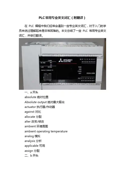
PLC常用专业英文词汇(附翻译)在PLC编程中我们经常会遇到一些专业英文词汇,对于入门的学员来说过理解起来是非常困难的。
本文总结了一些PLC常用专业英文词汇,并做已翻译。
一、a开头absolute 绝对位置Absolute output 绝对最大输出actuator 执行器/作动器against 对比allocate 分配alter 改变/修改ambient 环境周围ambient operating temperatureanalog 模拟analysis 分析applicable 可用assign 分配二、b开头back up battey 备用电池barcode reader/ID 条形码阅读器base unit 主基板baud 波特beforehand 事先binary 二进制buffer memory 缓冲存储器bus 总线三、c开头case 外壳characteristic 特征check 校验child-station 子站common terminal 公共端compatible 兼容compound 混合condensation 结露condition 条件conductive 导电configuration 组态configure 组态confirm 确认consumption 消耗content 目录control level 控制级convenient 方便conventionaly 传统conversion 转换converter 转换器conveyor 传送corrosive 腐蚀cutoff 切断countermeasure 对策四、d开头debug 调试dedicated 屏蔽dedicated 专用default value 缺省值define 解释/阐明design 设计device level 现场级diagnosis 诊断digital 数字din rail 导轨diverse 不同的/各种各样的download 下载duplicate 完全一样dust 灰尘五、e开头eliminate 免得enterprise level 管理级erase 清除exceed 超出execute 执行expand 扩展六、f开头faulty 故障站field bus 现场总线fix 固定flexibly 灵活的flow 流量format 格式fuse 融丝七、g开头graph图标坐标图曲线guaranteed 担保八、h开头handle 处理hardware manual 硬件手册hint 提示humidity 湿度九、i开头individual 独立的inductance 电感initiate 实施发起input 输入input point 输入点数install 安装instruction 指令insulation 隔离interface 接口interlocking 互锁internal 内部interrupt 中断invalid 无效十、m开头magnetic 有磁性的main circuit 主回路/线电路malfunction 故障mandatory 强制mantenance 维护manual 手册mechanical 机械mechanical life 机械寿命module 模块/组件momentary power failure 瞬时断电monitor 监视mount 固定multiple 多样十一、n开头negative 负十二、o开头observation 观察occupy 占用occur 发生offline 离线offset gain 偏置增益oil mist 油雾optical loop 光缆回路optimum 最佳的output 输出overall 总的overview 总揽十三、p开头parameter 参数path 路径perform 进行performance specifations 性能规格peripheral 外围/外部设备phase 相point 要点port 接口positive 正power line 电源线power>precaution 注意事项print board 印刷电路板procedure 过程programing interface 编程接口/编程界面protocol 协议十四、r开头range 范围rated input voltage 额定输入电压ratio 比率refer to 参照recommend 建议reduce 减少/缩小register 数据寄存器relay 继电器remote I/O 远程网络reserved station 预留主站resistor 电阻器十五、l开头load bridging resistor 负载转移电阻load compensating resistor 负荷补偿电阻load shifting resistor 负载移动电阻器 ; 负荷转移电阻load-resistor contactor 负载电阻器接触器 ; 负荷电阻接触器anode load resistor 释义阳极负载电阻 ; 阳极负载电阻effect of load resistor 负载电阻效应十六、r开头resolution 分辨率Maximum resolution 最大分辨率restriction 限制retry 重试十七、s开头scan 扫描screw 螺丝seamless network 无缝网络sequence programme 顺控程序serial communications module 串口通信模块series 系列servo 伺服系统short 短路signal 信号sink 漏极slot 周边元件扩展插槽soures 源极specifications 特性stabilized power supply 稳压电源standby master station 备用主站start up 起动status 状态step drive 步进storage 存储store 存储witch off 切断swith 开关十八、t开头table 表格transfer 传送transistor 晶体管transmission speed 传输速度transmit 传送/传输triac 三端双向可控硅开关元件troubleshooting 故障处理十九、u开头unuseble 不可以使用upload 上传/上载utilize 利用二十、v开头verify 校验voltage 电压二十一、w开头watchdog 看门狗定时器width 范围wire chips 线头。
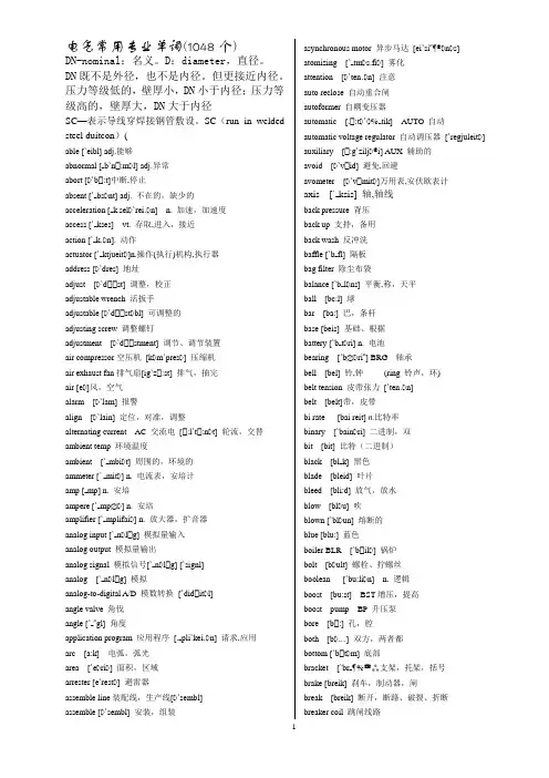
电气常用专业单词(1048个)DN-nominal:名义。
D:diameter,直径。
DN既不是外径,也不是内径。
但更接近内径。
压力等级低的,壁厚小,DN小于内径;压力等级高的,壁厚大,DN大于内径SC—表示导线穿焊接钢管敷设。
SC(run in welded steel duitcon)(able [`eibl] adj.能够abnormal [ b`n :m l] adj.异常abort [ `b :t]中断,停止absent [` bs nt] adj. 不在的,缺少的acceleration [ k.sel `rei n] n. 加速,加速度access [` kses] vt. 存取,进入,接近action [` k n]. 动作actuator [` ktjueit ]n.操作(执行)机构,执行器address [ `dres] 地址adjust [ `d st] 调整,校正adjustable wrench 活扳手adjustable [ `d st bl] 可调整的adjusting screw 调整螺钉adjustment [ `d stment] 调节、调节装置air compressor空压机[k m`pres ] 压缩机air exhaust fan排气扇[ig`z :st] 排气,抽完air [e ]风,空气alarm [ `lam] 报警align [ `lain] 定位,对准,调整alternating current AC 交流电[ :l`t :n t] 轮流,交替ambient temp 环境温度ambient [` mbi t] 周围的,环境的ammeter [` mit ] n. 电流表,安培计amp [ mp] n. 安培ampere [` mp ] n. 安培amplifier [` mplifai ] n. 放大器,扩音器analog input [` n l g] 模拟量输入analog output 模拟量输出analog signal 模拟信号[` n l g] [`signl]analog [` n l g] 模拟analog-to-digital A/D 模数转换[`did it l]angle valve 角伐angle [` gl] 角度application program 应用程序[. pli`kei n] 请求,应用arc [a:k] 电弧,弧光area [`e ri ] 面积,区域arrester [e`rest ] 避雷器assemble line装配线,生产线[ `sembl]assemble [ `sembl] 安装,组装asynchronous motor 异步马达[ei`si n s] atomizing [` tm s.fi ] 雾化attention [ `ten n] 注意auto reclose 自动重合闸autoformer 自耦变压器automatic [. :t ` tik] AUTO 自动automatic voltage regulator 自动调压器[`regjuleit ] auxiliary [ :g`zilj i] AUX 辅助的avoid [ `v id] 避免,回避avometer [ `v mit ]万用表,安伏欧表计axis [` ksis] 轴,轴线back pressure 背压back up 支持,备用back wash 反冲洗baffle [`b fl] 隔板bag filter 除尘布袋balance [`b l ns] 平衡,称,天平ball [bc:l] 球bar [ba:] 巴,条杆base [beis] 基础、根据battery [`b t ri] n. 电池bearing [`b ri ] BRG 轴承bell [bel] 铃,钟(ring 铃声,环)belt tension 皮带张力[`ten n]belt [belt]带,皮带bi rate [bai reit] n.比特率binary [`bain ri] 二进制,双bit [bit] 比特(二进制)black [bl k] 黑色blade [bleid] 叶片bleed [bli:d] 放气,放水blow [bl u] 吹blown [`bl un] 熔断的blue [blu:] 蓝色boiler BLR [`b il ] 锅炉bolt [b ult] 螺栓、拧螺丝boolean [`bu:li n] n. 逻辑boost [bu:st] BST增压,提高boost pump BP 升压泵bore [b :] 孔,腔both [b ] 双方,两者都bottom [`b t m] 底部bracket [`br 支架,托架,括号brake [breik] 刹车,制动器,闸break [breik] 断开,断路、破裂、折断breaker coil 跳闸线路breaker [`breik ]断路器,隔离开关brown [braun] 棕色brush [br ] 电刷,刷子bucket [`b kit] 斗,吊斗buffer n. [`b f 缓冲器bump [b mp] 碰,撞击burner [`b :n ] 燃烧器button [`b tn] 按钮bypass/by pass BYP 旁路byte [bait] 字节(八位)cabinet [`k binit] 厨柜,机箱、柜cable [`keibl] 电缆calculator [`k lkjuleit ] 计算器caliber [`k lib ] 管径、尺寸、大小cam [k m] 凸轮cancel [`k ns l] 取消、省略capacitance [k `p sit ns] n. 容量,电容capacitor [k `p sit ] n. 电容器=capacitator card [ka:d](电子)板、卡carton [`ka:t n] 纸板箱casualty [`k ju lti] 人身事故、伤亡、故障center [`sent ] 中心central control room 中控室central processing unit CPU 中央处理器centrifugal fan 离心风机centrifugal [sen`trifjug ] 离心的change [t 改变character [`k rikt ] 字符charge indicator 验电器、带电指示器:d 充电,电荷chassis earth 机壳接地chassis [` si] 底座、机壳check [t ek] 检查chimney [`t mni] 烟囱、烟道circuit [`s :kit] n. 电路circuit breaker 电路断路器circuit diagram 电路图[`dai grcircuitry [`s :kitri] n.电路,线路circulating water pump 循环水泵circulating 循环[`s :kjuleiti ]clamp [kl mp] 夹具、钳class of insulation 绝缘等级[.insju`lei n] class [kla:s] 类、等级、程度clean [kli:n] 清洁的、纯净的cleanse [kle 净化、洗净、消毒CLEARING OF FAULT 故障清除clockwise [`kl kwaiz] 顺时针、右旋的clog [kl g] 障碍,塞满,粘注close [kl uz] 关闭closed-loop 闭环[lu:p]coarse [k :s] 粗的、不精确的code [k ud] 代号、密码coder [`k ud ] 编码器coil [k il] n.线圈cold [k uld] 冷,冷的,感冒collect [k `lekt] 收集colour [`k l ] 颜色command [k `ma:nd] 命令、指挥communication [k .mju:ni`kei 通信、通讯compensation [k mpen`sei n]补偿,矫正component [k m`p un nt] 元件compress air 压缩空气[ ]compress [k m`pres] 压缩compressor [k m`pres ] 压缩机computer [k m`pju:t ] 计算机condensate [k n`denseit] 冷凝、使凝结condition [k n`di n] 条件、状况、环境conduct [`k nd kt] 传导conductivity [.k nd k`tiviti] 导电率conductor [k n`d kt ] n.导体,导线configure [k n`fig ] 组态congealer [k n`d i:l ] 冷却器、冷冻器connect [k `nekt] 连接connection [k `nek n] 联接connector [k `n kt ] 联接器、接线盒console [k n`s ul] 控制台constant [`k nst nt] 恒定的contact [`k nt kt] n.接触,触点,vt.接触,联系contact to earth 接地、触地、碰地[ : ] contact [`k nt kt] 触点contactor [`k nt kt ] (电流)接触器、触头continuous [k n`tinju s] 连续的control [k n`tr l] CNTR/CNTPL 控制control panel 控制盘[`p nl] 面板,仪表板,屏幕control valve 调节阀[v lv]controller [k n`tr ul ] 控制器convert [k n`v :t]n.转换vt.使转变,转换…. conveyor [k n`vei ] 传送带,输送机cooktop [`kukt p] n.炉灶cool [ku:l] 冷的cooler [`ku:l ] 冷却器cooling fan 冷却风机[f n]cooling tower 冷却塔[`tau ] 塔,城堡cooling water pump 冷却水泵cooling [`ku:li ] 冷却copy [`k pi] 拷贝core [k :] 铁心、核心、磁心correct [k `rekt] 正确的,改正correction [k `rek n] 修正、改正corrosion [k `r u n] 腐蚀counter [`kaunti ] n.计数器couple [`k pl] CPL 联轴器curdle [`k :dl] 凝固currency [`k r nsi] 流动、流通current [`k r nt] n. 电流,水流、当前、气流current transformer CT 电流互感器[tr ns`f :m ] cursor [`k :s ] 光标curve [k :v] 曲线cutter [`k t ] 切削工具,刀具ccycle 循环、周期、周波cylinder [`silind ] CYL 汽缸,圆柱体cymometer [sai`m mit ] 频率表,频率计damage [`d mid ] 损坏、破坏danger zone 危险区[z un]danger [`deind ] 危险、危险物dangerous [`deind r s] 危险的dank [d k] 潮湿data base 数据库[beis] 底部,基层,灯座data pool 数据库[pu:l]data [`deit ] 数据deactivate [di:` ktiveit] 使无效dead band 死区[ded] [b nd] 区,队debugging [di:`b gi ] n.调试deceleration [di:.sel `rei n] n. 减速,减速度decrease [di:`kri:s] DEC 减少deep [di:p] 深度、深的、深default [di`f :lt] n. 默认(值),缺省(值)degree [di`gri:] 度、等级delay time 延时[di`lei] 延迟,滞后relay [`ri:lei] 继电器delay [di`lei] 延迟,滞后delete [di`li:t] 删除,作废defective [di`fektiv] 有缺陷的,损坏,次品,不完全description [dis`krip n] 说明、描述detect [di`tekt] 发现、检定detector [di`tekt ] 检测器,探测器deviate [`di:vieit] 背离、偏差device [di`vais] 设备、仪器,装置diagnosis [.dai g`n usis] 诊断diagram [`dai gr m] 图形、图表diameter [dai` mit ] 直径dielectric [.daii`lektrik] 介质、绝缘的diesel generator 柴油发电机[`di:z l] [`d en reit ]发电机,振荡器differential [.dif `ren ] 差别的,差动的,微分differential pressure DP/DSP 差压[`pre ]digital input/output 数字量输入/输出[`did itl] 数字的,数字digital signal 数字信号[`did itl][`signl]digital [`did itl] 数字的digital-to-analog D/A 数/模转换[` l g]direct current DC 直流(电)[di`rekt] 直接的disassembly [.dis `sembli] 拆卸disaster shutdown 事故停机[` tda n] 停工(机),关机disaster [di`za:st ] 事故、故障discharge 排除、放电、卸载disconnect switch 隔离开关disconnect 断开,分离disconnector 隔离器、隔离开关discrete [dis`kri:t] adj.不连续的,离散的discrete input 开关量输入discrete output 开关量输出disk [disk] 磁盘diskette [dis`ket] 磁盘,磁碟display [di`splei] 显示、列屏dissipation [.disi`pei n] n. 分配,分发distance [`dist ns] 距离,间隔distilled water DISTL WTR 蒸馏水[dis`tild] 由蒸馏得来的distributed control system DCS 集散控制系统distributed [dis`tribju:tid] 分布的distributing board 配电盘[dis`tribju:ti ] [b :d]double [`d bl] 两倍的,双重的dowel pin 定位销[`dau l] 销子[pin]down [daun] 向下的,向下download 下载downtime 停机时间drain DRN 疏水、排放drawing [`dr :i ] 画图.制图,图样、牵引drill [dril] 钻孔、钻头、钻床drive nail 钉钉子drive [draiv] 驱动、强迫drop [dr p] 滴,点滴,落下dry [drai] 干、干燥duct [d kt] 风道、管道dust catcher 除尘器、吸尘器[`k t ] 捕捉器dust [d st] 灰尘duty [`dju:ti] 责任,义务dynamic [dai`n mik] 动态的dynamometer [.dain `m mit ] 功率表earth connector 接地线、接地[ : ] [k `n ktearth fault 接地故障[f :lt]earth lead 接地线、接地[li:d] 引线,领导earth 大地[ : ]eccentricity [eksen`trisiti] 偏心、扰度edit [`edit] 编辑efficiency [i`fi ns] 效率ejected [i`d ekt] 喷射,驱逐,被放出的ejection [i`d ek n] 弹出,排出,喷出,喷射electric failure 触电[i`lektrik] 电的[`feilj ] 故障,失败electric spark 电火化[spa:k]electric [i`lektrik] 电的、电动的、导电的electrical machine 电机[m ` i:n] 机器,机械electrical service 供电[`s :vis] 维修,服务,管理electrical [i`lektrikl] 电的、电气的electric-hydraulic control 电/液控制[hai`dr :lik] [k n`trol] electrician [ilek`tri n] 电工electrode [i`lektre d] 电极electronic [ilek`tr nik] 电子的、电子学的electrostatic [i`lektr u`st tik] 静电的electrotechnics [i`lektr u`tekniks] 电工学、电工技术element [`elim nt]元件、零件、单元elevator [`eliveit ] n.电梯,升级机emergency [i`m :d nsi] EMERG 紧急事故empty [`empti]排空enable [i`neibl] 使能够,允许enclosure [in`kl u ] n.密封,外壳,包围encoder [in`k ud ] 编码器end cover 端盖end 末端、终结energy meter 电度表energy [`en d i] 能、能量engineer [.end i`ni ] 工程师enter [`ent ] 开始、使进入entry [`entri] 输入equipment [i`kwipm 设备error [`er ] 错误escape valve 安全阀[is`keip]event [i`vent] 事件exceed [ik`si:d] 超过excess [ik`ses] 超过、过度exciter [ik`sait ] 励磁机exit [`eksit] 出口expansion [iks` n n] EXP 膨胀explosion [iks`pl u n] 爆炸external [eks`t :nl] 外部的、表面的extra-high voltage 超高压[`ekstr ] 额外的,特大的factor [`f kt ] 因素、因数factory [`f kt ri] 工厂、制造厂failure [`feilj ] FAIL 失败,故障false [f :ls] 假的、错误的fan [f n] 风扇、风机fault [f :lt] 故障faultless [`f :ltlis]没有缺陷、完美的faulty operation 误操作[`f :lti] [. p `rei n]运算,工作features [`fi:t ] 特点feed [fi:d] 馈、供给feedback [`fi:db k] 反馈fiber optic 光纤[`faib ] 光纤,纤维[` ptik] 光学上的,视觉的field [fi:ld] n.现场,原野file [fail] 文件、锉刀fill [fil] 装填filter [`filt ] n. 过滤器,滤波器,滤网,filter differential pressure FILTR DP 滤网压差final [`fain ] 最后的fire pump 消防水泵fire [`fai ] 燃烧、火焰fireproof [`fai pru:f] 防火的、阻燃的fixed [fikst] 固定的、固定、确定、保护屏flank [fl k] 侧翼、侧面flash lamp 闪光灯flash light 闪光flash [fl ] 闪光、闪烁、闪蒸float-charge浮充电[fl ut] 浮动[t a:d ] 充电,电荷flow [fl u] 流量、流动flowmeter [`fl umi:t ] 流量计flue gas 烟气[g s] 气体,煤气,毒气,汽油flue [flu:] 烟道fluid [`fluid] 液体flux [fl ks] n. 流量,通量forbid [f `bid] 禁止force draft fan 送风机[dr :ft] 通风force [f :s] 强制form [f :m] 形式、形状、形成、构成format [`f :m t] 形式、格式frequency [`fri:kw nsi] 频率friction [`frik n] n. 摩擦,摩擦力from [fr m] 从、来自、今后full speed 额定频率fully [`fuli] 充分的、完全的fume [fju:m] 烟,冒烟function [`f k n] 功能fuse holder 保险盒[`h uld ]fuse [fju:z] 保险丝、熔断器fusible cutout 熔断开关[`fju:z bl]溶解的,可融的[`k taut]断流,保险装置gauge [ ed ] 仪表、标准gear pump 齿轮泵[ i ] [p mp]gear shift housing 变速箱[ ift]换挡,变化[`h uzi ]外壳,套gear [ i ] 齿轮gearbox 齿轮箱general control panel总控制屏[`d en r l]普通的,全面的,综合的generator [`d en reit ] n. 发电机gland seal 轴封[ l nd]填料函盖,密封压盖[si:l] 封,密封,填料glass-paper 砂纸go on 继续goal [ ul] 目的、目标graphics [` r fiks] 调节阀grease [ ri:s] 图形green [ ri:n] 绿色ground [ ra nd]地面,场所、接地earth[ : ]地球,接地、大地,泥土guide [ aid] 领路人、向导half [h :f] 一半、一半的halt instruction 停机指令[h :lt]停机,中断,暂停[in`str k n] halve [ha:v] vt. 二等分,平分hammer [`h m ] 锤子hand [h nd] 手,指针handle[`h ndl]vt.触摸,运用,买卖,处理,操作vi.搬运,易于操纵handwheel [`h ndwi:l] 手轮,驾驶盘hardware [`h :dw ] 硬件havoc [`h v k] n.严重破坏vt.损害heat [hi:t] 热、加热heater [`hi:t ] 加热器heating [`hi:ti ] 加热,供暖hertz [`h :ts] HZ 赫兹high pressure HP 高压history [`hist ri] 历史hold [h uld] 保持hopper [`h p ] 漏斗、料斗hose [h uz] 软管、水龙带hot circuit 通电线路[`s :kit]hot start 热态启动[st :t]hot [h t] 热的,热情的,辣的hydraulic [hai`dr :lik] 水力的,液压的,油压的,水压的I/O point 输入/输出点inboard [`inb :d] 内侧idle [`aidl] 空闲的,空载的、无效的ignitor [ig`nait ] 点火,点燃,点火器impedance [im`pi:d ns] 阻抗import [im`p :t] 进口、输入、引入impulse [`imp ls] 脉冲、冲击、冲量inch [int ] IN 英寸inching [`int i ] 缓动、点动increase [in`kri:s] INC 增加increment [`inkrim nt] 增量,加1,递增index [`indeks] 索引、指标,指针,指数indicate [`indikeit] 指示,显示,表明indicator [`indikeit ] 指示器inductance [in`d kt ns] 电感,自感应induction motor 异步电动机[in`d k n] 感应[`m ut ] inductive reactance 感抗[in`d ktiv]电感的,感应的[ri` kt ns]电抗inductor [in`d ] n.电感器,感应器inhibit [in`hibit] 禁止,抑制,约束init 初使化initial [i`ni l] 初始的,最初的inlet [`inlet] 入口input/output I/O 输入/输出insert [in`s :t] 插入inside [`in`said] 内侧、内部inspection [in`spek n] 观察、检查inspector [in`spekt ] n.检测install [in`st :l] 安装instruction [in`str k n] n. 指令,指导,指示,说明书,instrument panel 仪表盘[`p nl]instrument [`instrum nt] 仪器insufficient [.ins `fi nt] 不足的,不够的insulate [`insjuleit] 绝缘、隔离insulation [.insju`lei n] 绝缘insulator [`insjuleit ] n.绝缘体integer [`intid ] 整数integral [`inti r l] 积分,积分的interface [`int .feis] n.分界面,界面,接口interface [`int .feis] 接口interference [.int `fi r ns] 干扰、干涉intermediate relay 中间继电器[.int `mi:dj t]中间的,中级,中频internal [in`t :nl] 内部的,内部interrupt [.int `r pt] 中断into [`intu] 向内、进入,到…里,进入到…之内inverter [in`v :t ] 逆变器、反相器、非门isolator [`ais leit ] 隔离器、刀闸,分离器,绝缘体job [d b] 工作jumper [`d mp ] 跳线、跨接junction box 接线盒[`d k n]key [ki:] 键销、钥匙、键槽keyboard [`ki:b :d] 键盘kilovolt-ampere KV A 千伏安[`kil v lt` mpe ]kink [ki k] 弯曲、缠绕knack [n k] 技巧、窍门、诀窍knife-switch 闸刀开关label [`leibl] 标号、标签,商标,标志laboratory [l `b r t ri] 实验室ladder diagram 梯形图[`l d ] [`dai gr m]ladder logic Diagram 逻辑梯形图[`l d ik][`dai gr m] ladder [`l d ] 梯子、阶梯lamp [l mp] n.灯、光源last [la:st] 最后的,末尾的leak [li:k] 泄漏,漏,漏洞(动词)leakage [li:kid ] n. 漏,泄漏,渗漏least [li:st] 最少的、最小的left [left] 左length [le ] 长度level [`levl] 液位、水平lever [`li:v ] 杆,杠杆,控制杆lifebelt [laifbelt] 安全带、保险带lift [lift] 提、升light run 空转[lait] [r n]light [lait] 光,灯,轻,淡,日光,光亮,点,点燃,照亮lightning [`laitni ] 雷电limit [`limit] LMT 极限、限制limit switch [`limit] 限位开关limiter [`limit ] 限制器、限位开关line [lain] 线、直线list [list] 列表、目录liter [`li:t ] 公升little [`litl] 小的,少许,少的load [l ud] n. 负荷,负载load thrown on 带负荷[ r un]local attendant 现场值班员[ `tend nt]维护人员,值班人员,服务员local repair 现场检修[ri`p ] 修理,修补local [`l uk l] 当地的,局部,本地location [l u`kei n] 位置,定位,单元,场所lock [l k] 闭锁、密封舱、固定logger [`1 ] 记录器、拖车logic [`l d ik] 逻辑long [l ] 长loop [lu:p] 环、回路loose [lu:s] 松的、不牢固的loosen [`lu:sn] 松开、松动loss [l s] 损失、减少low [l u] 低lower [`l u ] 较低的、降低low-half 下半[h :f]lub oil pump 润滑油泵lub oil 润滑油lubricate [`lu:brikeit] LUB 润滑machine [m ` i:n] 机器,机械magnet [`m nit] 磁main wire 电源线[`wai ]main [mein] 主要的,主群组maintain [men`tein] 维修、维持、保养maintenance manual 检修手册[`m nju l]maintenance [`meintin ns] 维护、维护,检修、小修make [meik] 制造,是成为make sure 确定[ u ] 的确,对…有把握make up 补充(补给)malfunction [m l`f k n] 故障,出错、误动、失灵management [`m nid m nt] 管理、控制、处理man-machine interaction 人机对话[m n][m :` i:n][.int ` k n]man-machine interface MMI 人机接口[`int .feis] 界面,接口manometer [m `n mit ] 压力表manual reject MRE 手动切换[ri`d ekt]拒绝,排斥manual [`m nju l] 手动、手册manual/Auto station M/A STATION 手动/自动切换站mark [m :k] 型号、刻度、标志、特征master control room 主控室、中央控制室[k n`tr l]master [`m :st ]主人,主要,控制,师傅,正版material [m `ti ri l] n. 材料,原料maximum [`m ksim m] 最大,最大值,最高,mean [mi:n] 平均,平均值、中间的measure [`me ] 度量、测量,量,尺寸mechanical trip vlv 机械跳闸阀[mi`k nikl] [trip] 脱扣,解扣mechanical [mi`k nikl] 机械的、力学的mechanism [`mek niz m] 机械、力学、方法、装置、机构medial [`mi:dj l] 中间的、平均的medium [`mi:dj m] 中间的、中等的、装置、介质、工质melt [melt] 溶解,熔化memory [`mem ri]存储,存储器,记忆menu [`menju:] n. 菜单metal [`metl] 金属meter [`mi:t ] n.仪表,米,表meter switch 仪表开关method of operation 运行方式[. p `rei n]操作,运转method [`me d] 方法、规律、程序microphone [`maikr f n] 麦克风、话筒,传声器,扩音器microprocessor [maikr u`pr uses ] n.微处理器middle [`midl] MID 中间的,中间,当中,中型mill [mil] 磨、磨粉机、压榨机,铣刀mind [maind] 头脑、精神、介意minimum [`minim m] 最小的minor overhaul 小修[main ]次要,副修科目[.auv `h :l]检修,大修minute [mai`nju:t] 分钟misfill 误装mishandle [`mis`h ndl] 胡乱操作、误操纵misread [mis`ri:d] 错读miss [mis] 过错,避免,小姐,姑娘,故障,失败miss operation 误动作、误操作[. `rei n]mistake [mis`teik] 错误、事故mixer [`miks ] n. 搅拌器,混合器,混频器modem [`m ud m] 调制解调器modify [`m difai] 修改、更改modulating valve 调节阀[`m djuleit] [v lv]module [`m dju:l] n.模块,组件,模数moisture [`m ist ] 湿度、湿汽mold [m uld]模具monitor [`m nit ] n.监听器,监视器,监控器vt.&vi.监控month [m n ] 月more than 超过[m :] 更多的[ n] 与…相比较,比motor MTR 马达[`m ut ]motor winding 电动机组绕组[`waindi ] 绕组,线圈,绕,缠mount [maunt] 安装、固定mouse [maus] 鼠标move [mu:v] 移动multimeter [`m ltimit ] 万用表nail [neil] 钉子、钉钉子naught line 零线[`n :t] 零,无neck [nek] 颈,管颈needlepoint vlv 针阀[`ni:dlp int]negative pressure NEG PRESS 负压negative [`neg tiv] 负的network [`netw :k] 网络neutral line 中性线[`nju:tr l]中性的newly [`nju:li] 最近,重新、新地nipper [`nip ] 钳子、镊子noise remove 消音器[n iz][ri`mu:v]noise [n iz] 噪音no-loading 空载nominal power 额定功率[`n minl]标称的,额定的[`pau ] nominal [`n minl] 标称的、额定的normal closed contact常闭触点[`k nt kt]触头,触点,接点normal [`n :m l] 正常的、常规的normally [`n :m li] 正常地not available 无效、不能用[ `veil bl] 可用的,有用的nozzle [`n zl] 喷嘴number [`n mb ] 数字、号码、数目nut [n t] 螺母、螺帽occur [ `k :] 发生ohm [ um] n.欧姆oil breaker 油开关 [`breik ]oil gun 油枪 [g n]oil level 机油平面[`levl]oil [ il] 油oiler [` il ] 注油器,油商oilless [ lles] 缺油的on/off 开/关online [ nlain] 联机的,在线的open circuit 开路 [` up n][`s :kit]open-loop 开环 [lu:p]operating panel 操作盘 [` p reiti ][`p nl] operation [. p `rei n] 操作、运行operational log 运行记录[ . p `rei n][l ]operator keyboard 操作员键盘 [`ki:b :d]operator station 操作员站 [`stei n]operator [` p reit ] 操作员option switch 选择开关optional [` p n l] 可选的,选择orbit [` : 轨道,轨迹orientation [. rien`tei n] 方位,定向,定位original [ `rid n l] 初始的、原始的out 出、出口outboard [`autb :t] 外侧的outage [`autid ] 断电,停机,出故障outlet [`autlet] 出口output [`autput] 产量、产品、输出oven [` vn] n.烤箱over current 过流 [`k r nt]over loading 过载 [`l udi ]over voltage 过压 [`v ltid ]over [` uv ] 结束,上面的,过分的overcool [` uv ku:l] 过冷却overflow [` uv `fl u] 溢流overhaul [. uv `h :l] 大修,检修overhead [` uv hed] 顶部,高空,架空overheat [. uv `hi:t] 使过热overload [` uv `l ud]n.过载overload protection 过载保护[` uv `l ud][pr `tek n] package [`p kid ] 组件、包,插件packaging [`p kid i ] n.包装panel [`p nl] 屏、盘parameter [p `r mit ] 参数part [p :t] 部分、部件password [`p :sw :d] 口令,密码peak [pi:k] 峰值percent [p `sent] PCT 百分数percentage [p `sentid ] 百分比perfect [`p :fikt] 完全的、理想的performance [p `f :m ns] 完成、执行、性能periodic inspection 定期检查 [in`spek n]periodic [pi ri` dik] 周期的、循环的peripheral equipment 外围设备 [i`kwipm nt] peripheral [p `rif r l] 周围的,外围设备,周边的permanent [`p :m n nt] 永久的、持久的permit [p `mit] 允许PG 编程器phase not together 缺相、失相[feiz]相[t ` e ]共同phase [feiz] PH 阶段、状态、方面、相phase sequence 相序[`si:kw ns] 次序,顺序,时序phase voltage 相电压phase-failure protection 断相保护[`feilj ]phase-in 同步photoelectricity [.f ut uilek`trisiti] 光电piezometer [.pai `z mit ] 压力计pilot [`pail t] 导向、辅助的、控制的pipe [paip] 管、管道plan [pl n] 计划plant [pl :nt] 工场、车间plastic [`pl stik] 塑料PLC(programmable Logic Controller) 可编程序逻辑控制器pliers [`plai z] 钳子、老虎钳plug socket 插座[`s kit]plug [pl ] 塞子、栓、插头plus [pl s] 加pneumatic [nju`m tik] 气动的point [p int] 点pointer [`p int ] 指针,指示器pole [p ul] 极、柱,极点,电极,电杆pollution [p `lu: n] 污染portion [`p : n] 一部分position [p `zi n] POS 位置potential [p `ten l] 电势,电位potential transformer PT 电压互感器[p `ten l][tr ns`f :m ] power failure 停电[`pau ] [`feilj ]故障,失败power [`pau ] PWR 功率、电源,能力,动力PPI(point-to-point Interface)点对点接口preblow 预吹preferential [.pref `ren l] n. 优先的,优先权perform [p `f :m] 预先形成,预制,预成型坯,粗加工的成品preheat [`pri:hi:t] 预热preheater [`pri:hi:t ] 预热器preliminary [pri`limin ri] 准备工作present [pri`zent] 出现preset [`pri:`set] 预设、预置press [pres] 压,按,压力pressure [`pre ] PRES 压力primary [`praim ri] 初级的、一次的principle [`prins pl] 原理、原则printer [`print ] 打印机probe [pr ub] 探头process [pr `ses] 过程、方法production [pr `d k n] 生产、产品、作品program [`pr u r m] 程序programmable [`pr ugr m bl] adj.可设计的,可编程的prohibit [pr `hibit] 禁止proportional / integral / derivative PID 比例/积分/微分protection [pr `tek n] PROT 保护、预防protocol [`pr ut k l] n.协议pull [pul] 拖,拉pulse [p ls] 脉冲、脉动pump body 泵体pump [p mp] 泵purge [p :d ]净化、吹扫push and pull switch 推拉开关push button 按钮push [pu ] 推pushbutton [pu `b tn] n. 按钮pyod [`pai d] 热电偶quality [`kw liti] 质量quit [kwit] 停止、离开、推出rack earth 机壳接地[r k] 机架,机柜,导轨[ : ]radiation fin 散热片[.reidi`ei n] 辐射,发散fin] 散热片radiator [`reidieit ] n. 散热器,冰箱raise [reiz] 升高range [reind ] 范围、量程rate [reit] 速度,速率rated power [`reitid] 额定功率rated [`reitid] 额定的、比率的ray [rei] 光线、射线read out 读出、结果传达reading 读数real time 实时的[`ri: l]receive tank 回收箱、接收箱[ri`si:v] [t k] receive [ri`si:v] 收到,接到,接收,接待recipe [`resipi] 处方、配方reclosing 重合闸recovery time 恢复时间[ri`k v ri]recovery [ri`k v ri] 恢复、再生rectification [.rektifi`kei n] 整流、检波、调整rectifier [`rektifai ] n.整流器,矫正器red 红色reduction [ri`d k n] 还原、缩小、降低redundancy [ri`d nd nsi] 冗余、多余reference [`refr ns] REF 参考、参照、证明书reflux [`ri:fl ks] 倒流、回流register [`red ist ] 寄存器regulate [`re juleit] 调节、控制relay [`ri:lei] n. 继电器release [ri`li:s] 释放reliability [i `biliti] 可靠性、安全的relief [ri`li:f] 去载、卸载、释放、解除relieve valve 安全阀、减压阀[ri`li:v] [v lv] remove 除去、拆卸renewal [ri`nju l] 更新、更换repair [ri`p ] 修理repairer 修理工、检修工repeat [ri`pi:t] 重复、反复replace [ri`pleis] 重新、启动、更换、替换replacement parts 备件、替换零件[ri`pleism nt][p :t] request [ri`kwest] REO 请求require [ri`kwai ] 要求reserve parts 备件[ri`z :v]reserved [ri`z :vd] 备用的reset [`ri:set] 复位resist [ri`zist] n.阻抗resistance [ri`zist ns] n.电阻、阻抗resolution [.rez `lju: n] n. 分辨率response [ris`p ns] 响应restart [ri:`st :t] 重新启动retighten [ri`tait n] 重新紧固retract [ri`tr kt] 可伸缩的、缩回return oil 回油[ri`t :n]return [ri`t :n] 返回reverse rotation 反转[ri`v :s]rig [ri ] 安装、装配、调整right [rait] 右right-of-way 公用线路ring [ri ] 环roller [`r ul ] 滚筒、辊子rotary switch 转换开关[`r ut ri]rotate [r u`teit] 旋转rotation [r u`tei n] 旋转,转动,回转rotor [`r ut ] 转子routine [ru:`ti:n] 例行的、日常的routing inspection 日常检查、日常检测[in`spek n] routing maintenance 日常维护[`ru:ti ] [`meintin ns] rubber [`r b ] 橡胶run back 返回run 运行safe [seif]安全的、可靠的、稳定的safety cap 安全帽safety [`seifti] 安全sample [`s mpl] 取样、举例sampling [`s :mpli ] 采样、抽样、取样saw [s :]锯scale [skeil] 刻度、衡量、比例尺、测量、铁锈水垢scan [sk n] 扫描schedule [` ekju:l] 时间表、计划表screen [skri:n]] 屏幕screw driver 螺丝刀screw socket 螺口插座screw [skru:] 螺杆、螺丝、旋转seal [si:l] 密封search [s :t ] 寻找、查找second [`sek nd] 秒、第二seep [si:p] 渗出、渗漏seepage [`si:pid ] 渗漏现象select [si`lekt] 选择selector [si`lekt ] 选择器self-hold [self] [h uld]自保持self-running 自启动send [send] 发送,寄,发射sensor [`sens ] 传感器sequence [`si:kw ns] 顺序、序列service manual 维修说明书series [`si ri:z] n.连续,串联service [`s :vis] 维修.保养.服务、伺服servo [`s :v u] 伺服servomotor [`s :v u.m ut ] 伺服电机set up 安装、调整、建立set [set] 设定shaft [ :ft] 轴、手柄、矿井shake [ eik] 摇动、振动shield [ i:ld] 屏蔽shift [ ift] 值、替换shock [ k] 震动,使受电击short circuit 短路short [ :t] 短的、短路、使短路should [ ud]应该,将要show [ u] 展览,显示,指示shut off 关闭[ t] 关闭,关上shut [ t] 关上,更加shutdown [` tda n] 停止、停机siccative [`sik tiv] 干燥剂,使干燥的,side [said] 侧边siemens [`si:m z] 西门子sifter [`sift ] 筛子、滤波器sign [sain] 标记、注册signal lamp 信号灯signal [`si nl] 信号,发信号silencer [`sail ns ] 消音器simulation [.s imju`lei n]n.仿真,模拟simulator [`simjuleit ] 仿真机single blade switch 单刀开关[bleid] 刀刃,刀片single [`si l] 单个的、个体的site [sait] 现场size [saiz] 尺寸、大小skip [skip] 空指令、跳跃smoke [sm uk] 烟、冒烟smokes-stack 烟囱[st k] 烟囱,堆,堆栈smooth [smu: ] 平滑的、光滑的socket wrench 套筒扳手socket [`s kit] 插座software [`s ft ] 软件solenoid [`s ulin id] 电磁线圈solid wrench 呆扳手solid [`s lid] 固体、坚固的、固体的source [s :s] 源、电源spanner [`sp n ] 扳手spare [sp ] 备用的、空余的spare parts 备件、备品spark [sp :k] 火花special tool 专用工具special [`spe l] 特别的、专门的specification [.spesifi`kei n] 技术要求,说明书speed [spi:d] 速度spray nozzle 喷嘴[sprei] 喷雾,喷射spring clutch 弹簧离合器[kl ] 离合器spring [spri ] 弹簧、春天stack [st k] 烟囱,堆栈stall [st :l] 停车、阻止standard [`st nd d] 标准standby [`st ndbai] 备用、待机star [st :] 星、星形连接start up 启动start [st :t] 启动、开始starter [`st :t ]n.启动器,启动钮starting conditions 启动条件[`sta:ti ] 启动,开始,出发start-up sequence 启动程序[`si:kw ns] 程序,次序,顺序,序列state [steit] 状态statement [`steitm nt] 声明、语句station [`stei n] 站、台,岗位,身份,地点,发电厂,位置stator coil 定子线圈stator core 定子铁芯[k :]stator [`steit ] 定子status display 状态显示status [`steit s] 状态stability [st `biliti] 稳定性steam [sti:m] STM 蒸汽step [step] 步,步幅step-by-step 步进式,逐步,按部就班的step-by-step motor 步进电动机step-down transformer 降压变压器step-up transformer 升压变压器still [stil] 仍然,还,更stop [st p] 停止storage battery 蓄电池storage [`st rid ] 储存strainer [`strein ] 滤网,过滤器streamline [`stri:mlain] 流水线stretching [`stret i ]拉伸,伸长suction pump 真空泵[`s k n]吸入,抽气,superheater [`sju:p hi:t ] 过热器supply [s `plai] 供给support [s `p :t] 支持、支撑sure [ u ] 确信的、可靠的switch [swit ] n. 开关,电闸switch blade 开关闸刀[bleid] 刀刃,刀片switch [swit ] 开关、切换switching off 断开[`swit i ]switching on 接通switching push button 开关按钮symbol [`simb l] 符号synchro [`si kr u]同步,同步机synchronization [.si kr nai`zei n] 同步synchronizer [`si kr naiz ] 同步器syren [`sai r n] 汽笛、报警器syringe [`sirind ] 注油器system unit 主机system [`sist m] 系统tab [t b] 表格,制表tachogenerator [`t k `d en reit ] 测速发电机tandem [`t m] 串联tank [t k] 箱temperature compensation 温度补偿[k mpen`sei n] temperature [`temprit ] 温度tensile [`tensail] 拉力的、张力的tension [`ten n] 压力、拉紧、张力terminal [`t :minl] n. 终端,接线端,电路接头test [test] 检测、试验tester [`test ] 检测者、检测器text [tekst] 出口thermal conduction 热传导[` :m l] 热的[k n`d k n]传导,导电thermal couple 热电偶[`k pl] 电偶,偶合thermal [` :m l] 热的,热量的,由热驱动的thermometer [ `m mit ] 温度计thermostat [` :m st t] 自动调温器,稳定调节装置,恒温器throttle [` r tl] 节流thrust [ r st] 冲击、推力thyristor [ ai`rist ] 晶闸管tight [tai] 紧密的、紧固的tighten [`tait n] 扣紧、变紧time-lag relay 延时继电time-lag 时间间隔timing [`taimi ] n.计时器,定时器toggle switch [`togl] 拨动开关token [`t uk n] 标志tong-test ammeter 钳式电流表[t ]钳tool box 工具箱tool [tu:l] 工具torque wrench 扭力扳手torque [t :k] 扭矩、力矩total [`t utl] 总计的training officer 培训主管[`treini ] 训练,练习transducer XDUCER 传感器、交流器,变频器transfer 转换transformer XFORMER 变压器,传感器,发送器transmission 传输transmitter XMItEER 变送器transwitch 可控硅开关travel [`tr vl] 过程、运转、进行、移动trigger [`tri ] 触发器trip [trip] 跳闸、断开tri-way vlv 三通阀trouble [`tr bl] 事故、故障、干扰true [tru:] 真实的、调整、校正try [trai] 尝试试图努力tune [tju:n] 调节,曲调tuning [`tju:ni ] 调谐turn [t :n] 转动、转向twist drill 麻花钻[twist] 扭转,扭曲type [taip] 类型、标志unbolt [` nb ult] 取下螺栓unclean [` n`kli:n] 脏的underground cable 地下电缆[` nd 地下的under voltage 欠压、电压低uninterrupted power supply UPS不间断电源[` nint `r ptid]连续unit [`ju:nit] 单元、单位unload [` n`l ud] 减负荷,卸载,放电unlock [` n`l k] 打开、解锁、释放unprotected [` npr `tektid] 未保护的、无屏蔽的untight [ n`tait] 松动的up 向上update [ p`deit] 更新、修改、校正upgrade [` p reid] 升级(优先级)提高/改进up-half 上部、上半[h :f]upper [` p ] 上部的,上面的use [ju:s] 使用,利用user [`ju:z ] 用户,使用者uninsulate [ n`insjuleit] 不绝缘vacuum [`v kju m] n. 真空,空间,真空吸尘器vacuum pump 真空泵valid [`v lid] 有效地、正确valley load 低谷负荷[l ud] 负载,负荷value [`v lju:] 数值valve [v lv] n. VLV 阀valve disk 阀芯valve seat 阀座vane [vein] 叶片variable [`v ri bl] 变量variator [`v rieit ] 变化器,变速器v-belt 三角皮带[belt]ventilation [venti`lei n] VENT 通风ventilator [`ventileit ] 通风机,风扇,通风设备vertical [`v :tik l] VERT 垂直的vessel [`vesl] 容器vibrate [vai`breit] (使)震动,摇摆vibration [vai`brei n] 振动11viscosity [vis`k siti] 粘度video display unit VDU 显示器[`vidi u] [di`splei] vision [`vi n] 视觉,视力,显示visor [`vaiz ] 护目镜、观察孔voltage [`vaultid ] n. 电压,伏特数voltage drop 电压降[`v ultid ] [dr p] 滴,落下voltage transformer 电压互感器voltmeter [`v l t.mi:t ] n. 电压表volume [`w lju:m] 容积、体积wall temp 壁面温度[w :l] 墙,墙壁warning [`w :ni ] 报警wash [w ] 洗washer [`w ] 垫圈、补垫waste [weist] 浪费、废物watch [w t ] 手表,注视watchdog [`w t d ] 看门狗water [`w :t ] WTR 水wattage [`w tid ] n. 瓦特数wear [wi ] 穿,磨损weather [`we ] 天气week [wi:k] 星期、周weight [weit] 重量,重力weld [weld] 焊接wheel [wi:l] 轮,车轮,轮子,转盘while [wail] 一会儿white [wait] 白色winch [wint ] 卷扬机.windings [`waindi ] 绕组windows [`wind z] 窗口wire [`wai ] 电线、金属丝、接线without [wi `aut] 没有,不wood [wud] 木、木制的word [w :d] 字,词work [w :k] 工作workshop [`w :k p] 车间,工场worm drive 蜗杆转动worm [w :m] 涡轮、螺杆wrench [rent ] 扳手,拧wrong [r ] 错误的、失常的wye Y形接法year [j ] 年yellow [`jel u] 黄色zero drift 零点漂移[drif t]zero [`zi r u] 零,零位zone [z un] 区、层、带12。
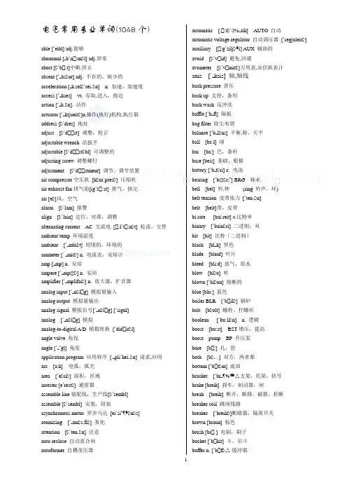
1电气常用专业单词able [`eibl] adj.能够abnormal [b`n :m l] adj.异常 abort [ `b :t]中断,停止absent [` bs nt] adj. acceleration [ k.sel `rei n] n. access [` kses] vt. 存取,action [` k n]. 动作actuator [` ktjueit ]n.操作(执行)机构address [ `dres] 地址 adjust [ `d st] 调整,校正 adjustable wrench 活扳手 adjustable [ `d st bl] 可调整的 adjusting screw 调整螺钉adjustment [ `d stment] air compressor 空压机 [k m`pres ] air exhaust fan 排气扇[ig`z :st] air [e ]风,空气 alarm [ `lam] 报警align [ `lain] 定位,对准,调整alternating current AC 交流电 [ :l`t ambient temp 环境温度ambient [` mbi t] 周围的,环境的ammeter [` mit ] n. amp [ mp] n. 安培 ampere [` mp ] n. 安培amplifier [` mplifai ] n. analog input [` n l g] 模拟量输入 analog output 模拟量输出analog signal 模拟信号[` n l analog [` n l g] 模拟analog-to-digital A/D 模数转换 [`did angle valve 角伐 angle [` gl] 角度application program 应用程序 [. arc [a:k] 电弧,弧光 area [`e ri ] 面积,区域 arrester [e`rest ] 避雷器assemble line 装配线,生产线[ assemble [ `sembl] 安装,组装asynchronous motor 异步马达 [ei`si atomizing [` tm s.fi ] 雾化 attention [ `ten n] 注意 auto reclose 自动重合闸 autoformer 自耦变压器[. :t ` tik] AUTO 自动自动调压器 [`regjuleit ] [ :g`zilj i] AUX 辅助的 `v id] 避免,回避[ `v mit ]万用表,安伏欧表计ksis] 轴,轴线背压 反冲洗 fl] 隔板 除尘布袋l ns] 平衡,称,天平 球 巴,条杆 基础、根据 battery [`b t ri] n. 电池 [`b ri ] BRG 轴承 铃,钟 (ring 铃声,环) 皮带张力 [`ten n] 带,皮带 n.比特率 ri] 二进制,双 比特(二进制) k] 黑色 叶片 放气,放水 u] 吹 un] 熔断的 蓝色[`b il ] 锅炉 螺栓、拧螺丝 [`bu:li n] n. 逻辑 BST 增压,提高 BP 升压泵 :] 孔,腔 ] 双方,两者都 t m] 底部支架,托架,括号 刹车,制动器,闸 断开,断路、破裂、折断 跳闸线路]断路器,隔离开关 棕色 ] 电刷,刷子 kit] 斗,吊斗 f 缓冲器2bump [b mp] 碰,撞击 burner [`b :n ] 燃烧器 button [`b tn] 按钮 bypass/by pass BYP 旁路 byte [bait] 字节 (八位) cabinet [`k binit] cable [`keibl] 电缆calculator [`k lkjuleit] caliber [`k lib ] cam [k m] 凸轮cancel [`k ns l] 取消、省略capacitance [k `p sit ns] n. capacitor [k `p sit ] n. card [ka:d](电子)板、卡 carton [`ka:t n] 纸板箱casualty [`k ju lti] center [`sent ] 中心 central control room 中控室central processing unit CPU centrifugal fan 离心风机 centrifugal [sen`trifjug ] change [t 改变 character [`k rikt ] 字符charge indicator :d chassis earth 机壳接地 chassis [` si] 底座、机壳 check [t ek] 检查chimney [`t mni] 烟囱、烟道circuit [`s :kit] n. 电路 circuit breaker 电路断路器 circuit diagram 电路图 [`dai gr circuitry [`s :kitri] n.circulating water pump circulating 循环 [`s :kjuleiti clamp [kl mp] 夹具、钳class of insulation 绝缘等级 class [kla:s] 类、等级、程度 clean [kli:n] 清洁的、纯净的cleanse [kle CLEARING OF FAULT clockwise [`kl kwaiz] clog [kl g] close [kl uz] 关闭 closed-loop 闭环 [lu:p] coarse [k :s] [k ud] 代号、密码 [`k ud ] 编码器 il] n.线圈[k uld] 冷,冷的,感冒 [k `lekt] 收集 [`k l ] 颜色[k `ma:nd] 命令、指挥[k .mju:ni`kei 通信、通讯 mpen`sei n]补偿,矫正 component [k m`p un nt] 元件 compress air 压缩空气 [ ] compress [k m`pres] 压缩 [k m`pres ] 压缩机 [k m`pju:t ] 计算机 [k n`denseit] 冷凝、使凝结 [k n`di n] 条件、状况、环境 [`k nd kt] 传导[.k nd k`tiviti] 导电率 [k n`d kt ] n.导体,导线 [k n`fig ] 组态[k n`d i:l ] 冷却器、冷冻器 [k `nekt] 连接 [k `nek n] 联接 [k `n kt ] 联接器、接线盒 [k n`s ul] 控制台 [`k nst nt] 恒定的[`k nt kt] n.接触,触点,vt.接触,联系 接地、触地、碰地 [ : ] [`k nt kt] 触点[`k nt kt ] (电流)接触器、触头 [k n`tinju s] 连续的 [k n`tr l] CNTR/CNTPL 控制 控制盘 [`p nl] 面板,仪表板,屏幕 调节阀 [v lv] [k n`tr ul ] 控制器n`v :t]n.转换 vt.使转变,转换…. [k n`vei ] 传送带,输送机 p] n.炉灶 [ku:l] 冷的 [`ku:l ] 冷却器 冷却风机 [f n] 冷却塔 [`tau ] 塔,城堡 冷却水泵 ] 冷却 [`k pi] 拷贝:] 铁心、核心、磁心3correct [k `rekt] 正确的,改正 correction [k `rek n] 修正、改正 corrosion [k `r u n] 腐蚀 counter [`kaunti ] n.计数器 couple [`k pl] CPL 联轴器 curdle [`k :dl] 凝固currency [`k r nsi] 流动、流通current [`k r nt] n. current transformer CT 电流互感器 cursor [`k :s ] 光标 curve [k :v] 曲线 cutter [`k t ] 切削工具,刀具 ccycle 循环、周期、周波cylinder [`silind ] CYL cymometer [sai`m mit ] damage [`d mid ] 损坏、破坏 danger zone 危险区 [z un] danger [`deind ] 危险、危险物 dangerous [`deind r s] 危险的 dank [d k] 潮湿data base 数据库[beis] data pool 数据库 [pu:l] data [`deit ] 数据deactivate [di:` ktiveit] 使无效 dead band 死区 [ded] [b nd] 区,队 debugging [di:`b gi ] n.调试deceleration [di:.sel `rei n] n. decrease [di:`kri:s] DEC 减少 deep [di:p] 深度、深的、深 default [di`f :lt] n. 默认(值),缺省(值degree [di`gri:] 度、等级delay time 延时 [di`lei] 延迟,滞后 delay [di`lei] 延迟 ,滞后 delete [di`li:t] 删除,作废defective [di`fektiv] description [dis`krip n] detect [di`tekt] 发现、检定detector [di`tekt ] 检测器,探测器 deviate [`di:vieit] 背离、偏差 device [di`vais] 设备、仪器,装置 diagnosis [.dai g`n usis] 诊断 diagram [`dai gr m] 图形、图表 diameter [dai` mit ] 直径dielectric [.daii`lektrik] diesel generator 柴油发电机[`di:z differential [.dif `ren ] pressure DP/DSP 差压 [`pre ]数字量输入/输出 [`did itl] 数字的,数字 数字信号[`did itl][`signl] [`did itl] 数字的数/模转换 [` l g] 直流(电) [di`rekt] 直接的 disassembly [.dis `sembli] 拆卸disaster shutdown 事故停机 [` tda n] 停工(机),关机 disaster [di`za:st ] 事故、故障 排除、放电、卸载 隔离开关 断开,分离隔离器、隔离开关 不连续的,离散的 开关量输入 开关量输出 [disk] 磁盘磁盘,磁碟 显示、列屏n] n. 分配,分发 [`dist ns] 距离,间隔DISTL WTR 蒸馏水 [dis`tild] 由蒸馏得来的 集散控制系统 [dis`tribju:tid] 分布的board 配电盘 [dis`tribju:ti ] [b :d] [`d bl] 两倍的,双重的 定位销 [`dau l] 销子 [pin] [daun] 向下的,向下 下载 停机时间 疏水、排放[`dr :i ] 画图.制图 ,图样、牵引 [dril] 钻孔、钻头、钻床 钉钉子 [draiv] 驱动、强迫 [dr p] 滴,点滴,落下 [drai] 干、干燥 [d kt] 风道、管道除尘器、吸尘器 [`k t ] 捕捉器 [d st] 灰尘 [`dju:ti] 责任,义务 [dai`n mik] 动态的[.dain `m mit ] 功率表接地线、接地 [ : ] [k `n kt 接地故障 [f :lt]接地线、接地 [li:d] 引线,领导4earth 大地 [ : ]eccentricity [eksen`trisiti] 偏心、扰度 edit [`edit] 编辑 efficiency [i`fi ns] 效率ejected [i`d ekt] 喷射,驱逐,被放出的 ejection [i`d ek n] 弹出,排出,喷出,喷射 electric failure 触电 [i`lektrik] 电的 [`feilj ] 故障,失败 electric spark 电火化 [spa:k]electric [i`lektrik] 电的、电动的、导电的 electrical machine 电机 [m ` i:n] 机器,机械 electrical service 供电 [`s :vis] 维修,服务,管理 electrical [i`lektrikl] 电的、电气的electric-hydraulic control 电/液控制 [hai`dr :lik] [k n`trol] electrician [ilek`tri n] 电工 electrode [i`lektre d] 电极electronic [ilek`tr nik] 电子的、电子学的 electrostatic [i`lektr u`st tik] 静电的electrotechnics [i`lektr u`tekniks] 电工学、电工技术 element [`elim nt]元件、零件、单元 elevator [`eliveit ] n.电梯,升级机emergency [i`m :d nsi] EMERG 紧急事故 empty [`empti]排空 enable [i`neibl] 使能够,允许enclosure [in`kl u ] n.密封,外壳,包围 encoder [in`k ud ] 编码器 end cover 端盖 end 末端、终结 energy meter 电度表 energy [`en d i] 能、能量 engineer [.end i`ni ] 工程师 enter [`ent ] 开始、使进入 entry [`entri] 输入 equipment [i`kwipm 设备 error [`er ] 错误escape valve 安全阀 [is`keip] event [i`vent] 事件 exceed [ik`si:d] 超过 excess [ik`ses] 超过、过度 exciter [ik`sait ] 励磁机 exit [`eksit] 出口expansion [iks` n n] EXP 膨胀 explosion [iks`pl u n] 爆炸 external [eks`t :nl] 外部的、表面的extra-high voltage 超高压 [`ekstr ] 额外的,特大的factor [`f kt ] 因素、因数 factory [`f kt ri] 工厂、制造厂] FAIL 失败,故障 假的、错误的 风扇、风机 故障:ltlis]没有缺陷、完美的误操作 [`f :lti] [. p `rei n]运算,工作 ] 特点 馈、供给 k] 反馈光纤 [`faib ] 光纤,纤维 [` ptik] 光学上的,视觉的 现场,原野 文件、锉刀 装填] n. 过滤器,滤波器 ,滤网, filter differential pressure FILTR DP 滤网压差 [`fain ] 最后的 消防水泵 燃烧、火焰[`fai pru:f] 防火的、阻燃的 固定的、固定、确定、保护屏 k] 侧翼、侧面 闪光灯 闪光] 闪光、闪烁、闪蒸浮充电[fl ut] 浮动 [t a:d ] 充电,电荷 u] 流量、流动 [`fl umi:t ] 流量计 [g s] 气体,煤气,毒气,汽油 烟道 液体n. 流量,通量 `bid] 禁止送风机 [dr :ft] 通风 :s] 强制形式、形状、形成、构成 :m t] 形式、格式 [`fri:kw nsi] 频率 n] n. 摩擦,摩擦力 m] 从、来自、今后 额定频率充分的、完全的 烟,冒烟 [`f k n] 功能 保险盒 [`h uld ] 保险丝、熔断器熔断开关[`fju:z bl]溶解的,可融的[`k taut]断流,保险装置gauge [ ed ] 仪表、标准gear pump 齿轮泵[ i ] [p mp]gear shift housing 变速箱[ ift]换挡,变化[`h uzi ]gear [ i ] 齿轮gearbox 齿轮箱general control panel总控制屏[`d en r l]generator [`d en reit ] n. 发电机gland seal 轴封[ l nd]填料函盖,密封压盖[si:l]glass-paper 砂纸go on 继续goal [ ul] 目的、目标graphics [` r fiks] 调节阀grease [ ri:s] 图形green [ ri:n] 绿色ground [ ra nd]地面,场所、接地earth[ : ]地球,接地、大地,泥土guide [ aid] 领路人、向导half [h :f] 一半、一半的halt instruction 停机指令[h :lt]停机,中断,暂停halve [ha:v] vt. 二等分,平分hammer [`h m ] 锤子hand [h nd] 手,指针handle[`h ndl]vt.触摸,运用,买卖,处理,操作vi.搬运handwheel [`h ndwi:l] 手轮,驾驶盘hardware [`h :dw ] 硬件havoc [`h v k] n.严重破坏vt.损害heat [hi:t] 热、加热heater [`hi:t ] 加热器heating [`hi:ti ] 加热,供暖hertz [`h :ts] HZ 赫兹high pressure HP 高压history [`hist ri] 历史hold [h uld] 保持hopper [`h p ] 漏斗、料斗hose [h uz] 软管、水龙带hot circuit 通电线路[`s :kit]hot start 热态启动[st :t]hot [h t] 热的,热情的,辣的hydraulic [hai`dr :lik]I/O point 输入/输出点inboard [`inb :d] 内侧idle [`aidl] 空闲的,空载的、无效的ignitor [ig`nait ] 点火,点燃,点火器impedance [im`pi:d ns] 阻抗import [im`p :t] 进口、输入、引入impulse [`imp ls] 脉冲、冲击、冲量inch [int ] IN 英寸[`int i ] 缓动、点动[in`kri:s] INC 增加[`inkrim nt] 增量,加1,递增[`indeks] 索引、指标,指针,指数[`indikeit] 指示,显示,表明[`indikeit ] 指示器[in`d kt ns] 电感,自感应异步电动机[in`d k n] 感应[`m ut ]感抗[in`d ktiv]电感的,感应的[ri` kt ns]电抗] n.电感器,感应器[in`hibit] 禁止,抑制,约束初使化l] 初始的,最初的[`inlet] 入口输入/输出insert [in`s :t] 插入inside [`in`said] 内侧、内部[in`spek n] 观察、检查[in`spekt ] n.检测[in`st :l] 安装k n] n. 指令,指导,指示,说明书,仪表盘[`p nl][`instrum nt] 仪器[.ins `fi nt] 不足的,不够的[`insjuleit] 绝缘、隔离[.insju`lei n] 绝缘] n.绝缘体[`intid ] 整数[`inti r l] 积分,积分的.feis] n.分界面,界面,接口[`int .feis] 接口`fi r ns] 干扰、干涉中间继电器[.int `mi:dj t]中间的,中级,中频[in`t :nl] 内部的,内部[.int `r pt] 中断[`intu] 向内、进入,到…里,进入到…之内[in`v :t ] 逆变器、反相器、非门leit ] 隔离器、刀闸,分离器,绝缘体[d b] 工作[`d mp ] 跳线、跨接box 接线盒[`d k n][ki:] 键销、钥匙、键槽[`ki:b :d] 键盘A 千伏安[`kil v lt` mpe ][ki k] 弯曲、缠绕[n k] 技巧、窍门、诀窍56knife-switch 闸刀开关label [`leibl] 标号、标签,商标,标志 laboratory [l `b r t ri] 实验室ladder diagram 梯形图 [`l d ] [`dai gr m] ladder logic Diagram 逻辑梯形图[`l d ik][`dai gr m] ladder [`l d ] 梯子、阶梯 lamp [l mp] n.灯、光源 last [la:st] 最后的,末尾的leak [li:k] 泄漏,漏,漏洞(动词) leakage [li:kid ] n. 漏,泄漏,渗漏 least [li:st] 最少的、最小的 left [left] 左 length [le ] 长度 level [`levl] 液位、水平 lever [`li:v ] 杆,杠杆,控制杆 lifebelt [laifbelt] 安全带、保险带 lift [lift] 提、升 light run 空转 [lait] [r n]light [lait] 光,灯,轻,淡,日光,光亮,点,点燃,照亮 lightning [`laitni ] 雷电 limit [`limit] LMT 极限、限制 limit switch [`limit] 限位开关 limiter [`limit ] 限制器、限位开关 line [lain] 线、直线 list [list] 列表、目录 liter [`li:t ] 公升little [`litl] 小的,少许,少的 load [l ud] n. 负荷,负载 load thrown on 带负荷 [ r un]local attendant 现场值班员 [ `tend nt]local repair 现场检修 [ri`p ] 修理,修补 local [`l uk l] 当地的,局部,本地location [l u`kei n] 位置,定位,单元,场所 lock [l k] 闭锁、密封舱、固定 logger [`1 ] 记录器、拖车 logic [`l d ik] 逻辑 long [l ] 长 loop [lu:p] 环、回路 loose [lu:s] 松的、不牢固的 loosen [`lu:sn] 松开、松动 loss [l s] 损失、减少 low [l u] 低lower [`l u ] 较低的、降低 low-half 下半 [h :f] lub oil pump 润滑油泵 lub oil 润滑油润滑,机械[`m nju l]维护、维护 ,检修、小修 …有把握 n] 故障,出错、误动、失灵 nt] 管理、控制、处理 人机对话` k n]人机接口 [`int .feis] 界面,接口 压力表[ri`d ekt]拒绝,排斥手动/自动切换站[k n`tr l]最大,最大值,最高,[mi`k nikl] [trip] 脱扣,解扣 机械的、力学的机械、力学、方法、装置、机构存储器,记忆 [. p `rei n]操作,运转n] 麦克风、话筒,传声器,扩音器 uses ] n.微处理器 ,中间,当中,中型 ,铣刀7minor overhaul 小修 [main ]minute[mai`nju:t] 分钟 misfill 误装mishandle [`mis`h ndl] misread [mis`ri:d] 错读miss [mis] miss operation 误动作、误操作 [. mistake [mis`teik] 错误、事故mixer [`miks ] n. 搅拌器,混合器,modem [`m ud m] 调制解调器 modify [`m difai] 修改、更改modulating valve 调节阀 [`m module [`m dju:l] n.moisture [`m ist ] 湿度、湿汽 mold [m uld]模具monitor [`m nit ] n.vt.&vi.监控 month [m n ] 月more than 超过[m :] 更多的[ n] 与…motor MTR 马达 [`m ut ]motor winding 电动机组绕组 mount [maunt] 安装、固定 mouse [maus] 鼠标 move [mu:v] 移动multimeter [`m ltimit ] 万用表 nail [neil] 钉子、钉钉子 naught line 零线 [`n :t] 零,无 neck [nek] 颈,管颈needlepoint vlv 针阀 [`ni:dlp int] negative pressure NEG PRESS 负压 negative [`neg tiv] 负的 network [`netw :k] 网络neutral line 中性线 [`nju:tr l]中性的 newly [`nju:li] 最近,重新、新地 nipper [`nip ] 钳子、镊子noise remove 消音器 [n iz][ri`mu:v] noise [n iz] 噪音 no-loading 空载nominal power 额定功率[`n minl]nominal [`n minl] 标称的、额定的normal closed contact 常闭触点 [`k normal [`n :m l] 正常的、常规的 normally [`n :m li] 正常地not available 无效、不能用 [ `veil nozzle [`n zl] 喷嘴number [`n mb ] nut [n t] 螺母、螺帽:] 发生 欧姆油开关 [`breik ] [g n]机油平面[`levl]il ] 注油器,油商 lles] 缺油的 开/关nlain] 联机的,在线的 开路 [` up n][`s :kit] 开环 [lu:p]操作盘 [` p reiti ][`p nl] p `rei n] 操作、运行 运行记录[ . p `rei n][l ] 操作员键盘 [`ki:b :d] 操作员站 [`stei n] p reit ] 操作员 选择开关 p n l] 可选的,选择 轨道,轨迹rien`tei n] 方位,定向,定位 `rid n l] 初始的、原始的:t] 外侧的] 断电,停机,出故障 出口产量、产品、输出 烤箱过流 [`k r nt] 过载 [`l udi ] 过压 [`v ltid ] ] 结束,上面的,过分的 uv ku:l] 过冷却 uv `fl u] 溢流 uv `h :l] 大修,检修 uv hed] 顶部,高空,架空 uv `hi:t] 使过热 uv `l ud]n.过载过载保护[` uv `l ud][pr `tek n] kid ] 组件、包,插件 kid i ] n.包装 nl] 屏、盘 `r mit ] 参数 部分、部件:sw :d] 口令,密码8peak [pi:k] 峰值percent [p `sent] PCT 百分数 percentage [p `sentid ] perfect [`p :fikt] performance [p `f :m ns] periodic inspection 定期检查periodic [pi ri` dik] peripheral equipment peripheral [p `rif r l] permanent [`p :m n nt] permit [p `mit] 允许 PG 编程器phase not together phase [feiz] PH phase sequence 相序 [`si:kw ns] phase voltage 相电压phase-failure protection 断相保护phase-in 同步photoelectricity [.f ut piezometer [.pai `z mit ] pilot [`pail t] pipe [paip] 管、管道 plan [pl n] 计划 plant [pl :nt] 工场、车间 plastic [`pl stik] 塑料pliers [`plai z] 钳子、老虎钳 plug socket 插座 [`s kit] plug [pl ] 塞子、栓、插头 plus [pl s] 加pneumatic [nju`m tik] 气动的 point [p int] 点pointer [`p int ] 指针,指示器 pole [p ul] pollution [p `lu: n] 污染 portion [`p : n] 一部分 position [p `zi n] POS 位置 potential [p `ten l] potential transformer PT power failure 停电 [`pau ] [`feilj power [`pau ] PWR PPI(point-to-point Interface)preblow 预吹preferential [.pref `ren l] n. perform [p `f :m] 预先形成,preheat [`pri:hi:t] 预热] 预热器 [pri`limin ri] 准备工作 [pri`zent] 出现 [`pri:`set] 预设、预置 [pres] 压,按,压力 ] PRES 压力 [`praim ri] 初级的、一次的 [`prins pl] 原理、原则 ] 打印机 [pr ub] 探头[pr `ses] 过程、方法[pr `d k n] 生产、产品、作品 [`pr u r m] 程序ugr m bl] adj.可设计的,可编程的 [pr `hibit] 禁止比例/积分/微分 protection [pr `tek n] PROT 保护、预防 protocol [`pr ut k l] n.协议 [pul] 拖 ,拉 ls] 脉冲、脉动 泵体 mp] 泵 :d ]净化、吹扫 推拉开关 按钮 [pu ] 推`b tn] n. 按钮[`pai d] 热电偶[`kw liti] 质量 [kwit] 停止、离开、推出机壳接地 [r k] 机架,机柜,导轨 [ : ] 散热片[.reidi`ei n] 辐射,发散 fin] 散热片 ] n. 散热器,冰箱 升高] 范围、量程 [reit] 速度,速率 额定功率 [`reitid] 额定的、比率的 [rei] 光线、射线 读出、结果传达 读数实时的 [`ri: l]回收箱、接收箱 [ri`si:v] [t k] [ri`si:v] 收到,接到,接收,接待 处方、配方 重合闸9recovery time 恢复时间 [ri`k v ri] recovery [ri`k v ri] 恢复、再生rectification [.rektifi`kei n] 整流、检波、调整 rectifier [`rektifai ] n.整流器,矫正器 red 红色reduction [ri`d k n] 还原、缩小、降低 redundancy [ri`d nd nsi] 冗余、多余 reference [`refr ns] REF 参考、参照、证明书 reflux [`ri:fl ks] 倒流、回流 register [`red ist ]寄存器 regulate [`re juleit] 调节、控制 relay [`ri:lei] n. 继电器 release [ri`li:s] 释放reliability [i `biliti] 可靠性、安全的 relief [ri`li:f] 去载、卸载、释放、解除 relieve valve 安全阀、减压阀[ri`li:v] [v lv] remove 除去、拆卸renewal [ri`nju l] 更新、更换 repair [ri`p ] 修理 repairer 修理工、检修工 repeat [ri`pi:t] 重复、反复replace [ri`pleis] 重新、启动、更换、替换 replacement parts 备件、替换零件[ri`pleism nt][p :t] request [ri`kwest] REO 请求 require [ri`kwai ] 要求 reserve parts 备件 [ri`z :v] reserved [ri`z :vd] 备用的 reset [`ri:set] 复位 resist [ri`zist] n.阻抗resistance [ri`zist ns] n.电阻、阻抗 resolution [.rez `lju: n] n. 分辨率 response [ris`p ns] 响应 restart [ri:`st :t] 重新启动 retighten [ri`tait n] 重新紧固 retract [ri`tr kt] 可伸缩的、缩回 return oil 回油 [ri`t :n] return [ri`t :n] 返回 reverse rotation 反转 [ri`v :s] rig [ri ] 安装、装配、调整 right [rait] 右 right-of-way 公用线路 ring [ri ] 环roller [`r ul ] 滚筒、辊子 rotary switch 转换开关 [`r ut ri] rotate [r u`teit] 旋转rotation [r u`tei n] 旋转,转动,回转[in`spek n] [`ru:ti ] [`meintin ns]] 采样、抽样、取样、旋转 自保持顺序、序列.保养.服务、伺服ut ] 伺服电机10should [ ud]应该,将要 show [ u] 展览,显示,指示 shut off 关闭 [ t] 关闭,关上 shut [ t] 关上,更加shutdown [` tda n] 停止、停机 siccative [`sik tiv] 干燥剂,使干燥的, side [said] 侧边siemens [`si:m z] 西门子 sifter [`sift ]筛子、滤波器sign [sain] 标记、注册 signal lamp信号灯 signal [`si nl] 信号,发信号 silencer [`sail ns ] 消音器simulation [.s imju`lei n]n.仿真,模拟 simulator [`simjuleit ] 仿真机single blade switch 单刀开关 [bleid] 刀刃,刀片 single [`si l] 单个的、个体的 site [sait] 现场 size [saiz] 尺寸、大小 skip [skip] 空指令、跳跃 smoke [sm uk] 烟、冒烟smokes-stack 烟囱 [st k] 烟囱,堆,堆栈 smooth [smu: ] 平滑的、光滑的 socket wrench 套筒扳手 socket [`s kit] 插座 software [`s ft ] 软件 solenoid [`s ulin id] 电磁线圈 solid wrench 呆扳手solid [`s lid] 固体、坚固的、固体的 source [s :s] 源、电源 spanner [`sp n ] 扳手 spare [sp ] 备用的、空余的 spare parts 备件、备品 spark [sp :k] 火花 special tool 专用工具special [`spe l] 特别的、专门的specification [.spesifi`kei n] 技术要求,说明书 speed [spi:d] 速度spray nozzle 喷嘴 [sprei] 喷雾,喷射 spring clutch 弹簧离合器 [kl ] 离合器 spring [spri ] 弹簧、春天 stack [st k] 烟囱,堆栈 stall [st :l] 停车、阻止 standard [`st nd d] 标准 standby [`st ndbai] 备用、待机 star [st :] 星、星形连接start up 启动start [st :t] 启动、开始starter [`st :t ]n.启动器,启动钮starting conditions 启动条件 [`sta:ti ] 启动,开始,出发 start-up sequence 启动程序 [`si:kw ns] 程序,次序,顺序,序列 state [steit] 状态statement [`steitm nt] 声明、语句station [`stei n] 站、台,岗位,身份,地点,发电厂,位置 stator coil 定子线圈 stator core 定子铁芯 [k :] stator [`steit ] 定子 status display 状态显示 status [`steit s] 状态 stability [st `biliti] 稳定性 steam [sti:m] STM 蒸汽 step [step] 步,步幅step-by-step 步进式,逐步,按部就班的 step-by-step motor 步进电动机 step-down transformer 降压变压器 step-up transformer 升压变压器 still [stil] 仍然 ,还,更 stop [st p] 停止 storage battery 蓄电池 storage [`st rid ] 储存 strainer [`strein ] 滤网,过滤器 streamline [`stri:mlain] 流水线 stretching [`stret i ]拉伸,伸长suction pump 真空泵 [`s k n] 吸入,抽气, superheater [`sju:p hi:t ] 过热器 supply [s `plai] 供给 support [s `p :t] 支持、支撑 sure [ u ] 确信的、可靠的 switch [swit ] n. 开关,电闸switch blade 开关闸刀 [bleid] 刀刃,刀片 switch [swit ] 开关、切换 switching off 断开 [`swit i ] switching on 接通switching push button 开关按钮 symbol [`simb l] 符号synchro [`si kr u]同步,同步机 synchronization [.si kr nai`zei n] 同步 synchronizer [`si kr naiz ] 同步器 syren [`sai r n] 汽笛、报警器 syringe [`sirind ] 注油器 system unit 主机system [`sist m] 系统tab [t b] 表格,制表tachogenerator [`t k `d en reit ] 测速发电机tandem [`t m] 串联tank [t k] 箱temperature compensation 温度补偿[k mpen`sei n] temperature [`temprit ] 温度tensile [`tensail] 拉力的、张力的tension [`ten n] 压力、拉紧、张力terminal [`t :minl] n. 终端,接线端,电路接头test [test] 检测、试验tester [`test ] 检测者、检测器text [tekst] 出口thermal conduction 热传导[` :m l] 热的[k n`d k n]传导,导电thermal couple 热电偶[`k pl] 电偶,偶合thermal [` :m l] 热的,热量的,由热驱动的thermometer [ `m mit ] 温度计thermostat [` :m st t] 自动调温器,稳定调节装置,恒温器throttle [` r tl] 节流thrust [ r st] 冲击、推力thyristor [ ai`rist ] 晶闸管tight [tai] 紧密的、紧固的tighten [`tait n] 扣紧、变紧time-lag relay 延时继电time-lag 时间间隔timing [`taimi ] n.计时器,定时器toggle switch [`togl] 拨动开关token [`t uk n] 标志tong-test ammeter 钳式电流表[t ]钳tool box 工具箱tool [tu:l] 工具torque wrench 扭力扳手torque [t :k] 扭矩、力矩total [`t utl] 总计的training officer 培训主管[`treini ] 训练,练习transducer XDUCER 传感器、交流器,变频器transfer 转换transformer XFORMER 变压器,传感器,发送器transmission 传输transmitter XMItEER 变送器transwitch 可控硅开关travel [`tr vl] 过程、运转、进行、移动trigger [`tri ] 触发器trip [trip] 跳闸、断开tri-way vlv 三通阀trouble [`tr bl] 事故、故障、干扰true [tru:] 真实的、调整、校正try [trai] 尝试试图努力调节,曲调[`tju:ni ] 调谐:n] 转动、转向麻花钻[twist] 扭转,扭曲类型、标志[` nb ult] 取下螺栓[` n`kli:n] 脏的地下电缆[` nd 地下的欠压、电压低不间断电源[` nint `r ptid]连续单元、单位[` n`l ud] 减负荷,卸载,放电[` n`l k] 打开、解锁、释放unprotected [` npr `tektid] 未保护的、无屏蔽的[ n`tait] 松动的p`deit] 更新、修改、校正p reid] 升级(优先级)提高/改进[h :f]p ] 上部的,上面的使用,利用] 用户,使用者[ n`insjuleit] 不绝缘kju m] n. 真空,空间,真空吸尘器真空泵lid] 有效地、正确低谷负荷[l ud] 负载,负荷lju:] 数值lv] n. VLV 阀阀芯阀座叶片[`v ri bl] 变量rieit ] 变化器,变速器[belt][venti`lei n] VENT 通风[`ventileit ] 通风机,风扇,通风设备[`v :tik l] VERT 垂直的容器[vai`breit] (使)震动,摇摆[vai`brei n] 振动[vis`k siti] 粘度显示器[`vidi u] [di`splei]n] 视觉,视力,显示] 护目镜、观察孔] n. 电压,伏特数1112voltage drop 电压降[`v ultid ] [dr p] 滴,落下 voltage transformer 电压互感器 voltmeter [`v l t.mi:t ] n. 电压表volume [`w lju:m] 容积、体积wall temp 壁面温度 [w :l] 墙,墙壁 warning [`w :ni ] 报警 wash [w ] 洗washer [`w ] 垫圈、补垫 waste [weist] 浪费、废物 watch [w t ] 手表,注视 watchdog [`w t d ] 看门狗 water [`w :t ] WTR 水 wattage [`w tid ] n. 瓦特数wear [wi ]穿,磨损 weather [`we ] 天气 week [wi:k] 星期、周 weight [weit] 重量,重力 weld [weld] 焊接wheel [wi:l] 轮,车轮,轮子,转盘 while [wail] 一会儿。
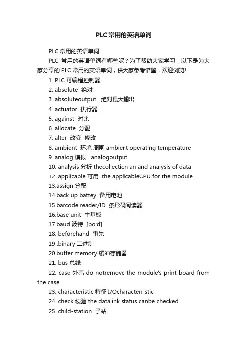
PLC常用的英语单词PLC常用的英语单词PLC常用的英语单词有哪些呢?为了帮助大家学习,以下是为大家分享的PLC常用的英语单词,供大家参考借鉴,欢迎浏览!1. PLC 可编程控制器2. absolute 绝对3. absoluteoutput 绝对最大输出4 .actuator 执行器5. against 对比6. allocate 分配7. alter 改变修改8. ambient 环境周围 ambient operating temperature9. analog 模拟 analogoutput10. analysis 分析 thecollection an and analysis of data12. applicable 可用 the applicableCPU for the module13.assign 分配14.back up battey 备用电池15.barcode reader/ID 条形码阅读器16.base unit 主基板17.baud 波特 [bo:d]18. beforehand 事先19 .binary 二进制20.buffer memory 缓冲存储器21. bus 总线22. case 外壳 do notremove the module's print board from the case23. characteristic 特征 I/Ocharacterristic24. check 校验 the datalink status canbe checked25. child-station 子站26. common terminal 公共端27. compatible 兼容 compatiblewith the MODBUS protocol28. compound 混合 compoundsystem communication [`compaund]29. condensation 结露30. condition 条件 conditionsetting31. conductive 导电 conductivemetal picees32. configuration 组态 systemconfiguration33. configure 组态34. confirm 确认 how toconfirm the operation of the module35. consumption 消耗 currentconsumption36. content 目录37. control level 控制级38. convenient 方便 moreconvenient and easy-to-use39. conventionaly 传统 whichconventionaly has been used40. conversion 转换 Analog-Digital conversion module41. converter 转换器42. conveyor 传送 conveyorline43. corrosive 腐蚀 corrosivegas44. countermeasure 对策countermeasure for mis-inpute45. cutoff 切断46. debug 调试 isrecommended before debugging47. dedicated 屏蔽 cc-linkdedicated cable48. dedicated 专用 dedicatedtransmission protocol49. default value 缺省值50. define 解释阐明 Offset value and gain value are defined as follow. [di`fain]51. design 设计 design asystem52. device level 现场级53. diagnosis 诊断 diagnosisfunction54. digital 数字 digitalinpute55. DIN rail 导轨56. diverse 不同的各种各样的57. download 下载58. duplicate 完全一样59. dust 灰尘60. eliminate 免得[i`limineit]61. enterprise level 管理级62. erase 清除63. exceed 超出 The numberadmitted must not exceed 20064. execute 执行 date linkis executed using these parameters65. expand 扩展 can beeapanded up to 255 networks66. faulty 故障站67. field bus 现场总线68. fix 固定69. flexibly 灵活的 to supporta variety systerm flexibly70. flow 流量71. format 格式transmission format [`fo:maet]72. fuse 融丝73. graph 图标坐标图曲线图voltage output characterristicgraph74. guaranteed 担保 nomaloperration cannot be guaranteed75. handle 处理76. hardware manual 硬件手册77. hint 提示 programminghints78. humidity 湿度 ambientoperating humdlity79. individual 独立的80. inductance 电感 inductanceload81. initiate 实施发起 can be initiate by a computer [i`nifieit]82. input 输入83. input point 输入点数84. install 安装85. instruction 指令 the FROMinstruction86. insulation 隔离form rubberprovides good insulation [,insju`leifn]87. interface 接口88. interlocking 互锁can be usedfor sequence program interlocking89. internal external 内部外部 internal connection90. interrupt 中断 excute aninterrupt processing91. invalid 无效 errorinvalid station function92. magnetic 有磁性的 magneticfields [maeg`netik]93. main circuit 主回路94. malfunction 故障 causesystem malfunction95. mandatory 强制96. mantenance 维护 maintenancecosts are reduced97. manual 手册 User'Manual98. mechanical 机械 michanicallife机械寿命99. module 模块 mount orremove the module [`modju:l]100. momentary power failure 瞬时断电101. monitor 监视102. mount 固定 mount orremove the module103. multiple 多样 mutipleremote i/o modules104. negative 负105. observation 观察106. occupy 占用 occupies 1station107. occur 发生108. offline 离线 offlinetest109. offset gain 偏置增益110. oil mist 油雾112. optical loop 光缆回路113. optimum 最佳的 optimumcontrol114. output 输出115. overall 总的 overalldistance116. overview 总揽communication overview117. parameter 参数118. path 路径transmission path119. per network120. perform 进行 normal datalink cannot be performed121. performance specifations 性能规格122. peripheral 外围Whenutilizing peripheral device to assign I/O number.123. phase 相 swith offall phases of the power supply [`feiz] 124. point 要点125. port 接口 Rs232c port126. positive 正127.power line 电源线128. power on/off 上电断电129. precaution 注意事项precaution when configuing system130. print board 印刷电路板131. procedure 过程 follow theprocedure132. programing interface 编程口133. protocol 协议 protocolcommunication issues134. range 范围135. rated input voltage 额定输入电压136. ratio 比率137. recommend 建议 isrecommended before debugging138. reduce 减少 the numberof steps in operation program can be reduced139. refer to 参照 refer toChapter 6140. register 数据寄存器141. relay 继电器 [`ri:lei]142. remote I/O 远程网络143. reserved station 预留主站144. resistor 电阻 resistorload阻性负载 terminating resistor 145. resolution 分解,解析 nMaximum resolution 最大分辨率146. restriction 限制 norestriction [ri`strikfn]147. retry 重试148. scan 扫描 link scan149. screw 螺丝 Teminal-block screw150. seamless network 无缝网络151. sequence programme 顺控程序152. serial communications module 串口模块153. series 系列154. servo 伺服155. short 短路156. signal 信号157. sink 漏极 sink commen158. slot 槽159. soures 源极 sourescommen160. specifications 特性 inputmodules specifications161. stabilized power supply 稳压电源162. standby master station 备用主站163. start up 起动164. status 状态 data linkstatus165. step drive 步进166. storage 存储 storagearea167. store 存储168. switch off 关断 swith offall phases of the power supply 169. swith 开关170. table 表格171. transfer 传输172. transistor 晶体管173. transmission speed 传输速度174. transmit 传送 data istransmitted in unchanged code175. triac 双端三相可控硅开关176. troubleshooting 故障处理177. unuseble 不可以使用178. upload 上传179. utilize 利用 Whenutilizing peripheral device to assign I/O number.180. verify 校验 verify theset parameter contents181. voltage 电压 highvoltage182. watchdog 看门狗183. width 范围it willvary in the width of [widθ]184. wire chips 线头【PLC常用的英语单词】。
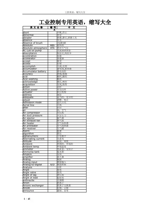
工业控制专用英语,缩写大全质量人员名称类QC quality control 品质管理人员FQC final quality control 终点质量管理人员IPQC in process quality control 制程中的质量管理人员OQC output quality control 最终出货质量管理人员IQC incoming quality control 进料质量管理人员TQC total quality control 全面质量管理POC passage quality control 段检人员QA quality assurance 质量保证人员OQA output quality assurance 出货质量保证人员QE quality engineering 质量工程人员质量保证类FAI first article inspection 新品首件检查FAA first article assurance 首件确认CP capability index 能力指数CPK capability process index 模具制程能力参数SSQA standardized supplier quality audit 合格供货商质量评估FMEA failure model effectiveness analysis 失效模式分析FQC运作类AQL Acceptable Quality Level 运作类允收质量水平S/S Sample size 抽样检验样本大小ACC Accept 允收REE Reject 拒收CR Critical 极严重的MAJ Major 主要的MIN Minor 轻微的Q/R/S Quality/Reliability/Service 质量/可靠度/服务P/N Part Number 料号L/N Lot Number 批号AOD Accept On Deviation 特采UAI Use As It 特采FPIR First Piece Inspection Report 首件检查报告PPM Percent Per Million 百万分之一制程统计品管专类SPC Statistical Process Control 统计制程管制SQC Statistical Quality Control 统计质量管理GRR Gauge Reproductiveness & Repeatability 量具之再制性及重测性判断量可靠与否DIM Dimension 尺寸DIA Diameter 直径N Number 样品数其它质量术语类QIT Quality Improvement Team 质量改善小组ZD Zero Defect 零缺点QI Quality Improvement 质量改善QP Quality Policy 目标方针TQM Total Quality Management 全面质量管理RMA Return Material Audit 退料认可7QCTools 7 Quality Control Tools 品管七大手法通用之件类ECN Engineering Change Notice 工程变更通知(供货商)ECO Engineering Change Order 工程改动要求(客户)PCN Process Change Notice 工序改动通知PMP Product Management Plan 生产管制计划SIP Standard Inspection Procedure 制程检验标准程序SOP Standard Operation Procedure 制造作业规范IS Inspection Specification 成品检验规范BOM Bill Of Material 物料清单PS Package Specification 包装规范SPEC Specification 规格DWG Drawing 图面系统文件类ES Engineering Standard 工程标准CGOO China General PCE龙华厂文件IWS International Workman Standard 工艺标准ISO International Standard Organization 国际标准化组织GS General Specification 一般规格部类PMC Production & Material Control 生产和物料控制PCC Product control center 生产管制中心PPC Production Plan Control 生产计划控制MC Material Control 物料控制DC Document Center 资料中心QE Quality Engineering 质量工程(部)QA Quality Assurance 质量保证(处)QC Quality Control 质量管理(课)PD Product Department 生产部LAB Laboratory 实验室IE Industrial Engineering 工业工程R&D Research & Design 设计开发部生产类PCs Pieces 个(根,块等)PRS Pairs 双(对等)CTN Carton 卡通箱PAL Pallet/skid 栈板PO Purchasing Order 采购订单MO Manufacture Order 生产单D/C Date Code 生产日期码ID/C Identification Code (供货商)识别码SWR Special Work Request 特殊工作需求L/N Lot Number 批号P/N Part Number 料号OEM Original Equipment Manufacture 原设备制造PC Personal Computer 个人计算机CPU Central Processing Unit 中央处理器A.S.A.P As Soon As Possible 尽可能快的E-MAIL Electrical-Mail 电子邮件N/A Not Applicable 不适用QTY Quantity 数量I/O input/output 输入/输出NG Not Good 不行,不合格C=0 Critical=0 极严重不允许APP Approve 核准,认可,承认CHK Check 确认ASS'Y Assembly 装配,组装T/P True Position 真位度5WIH When, Where, Who, What, Why, How to6M Man, Machine, Material, Method, Measurement, Message4MTH Man, Material, Money, Method, Time, How 人力,物力,财务,技术,时间(资源)SQA Strategy Quality Assurance 策略质量保证DQA Design Quality Assurance 设计质量保证MQA Manufacture Quality Assurance 制造质量保证SSQA Sales and service Quality Assurance 销售及服务质量保证LRR Lot Reject Rate 批退率SPS Switching power supply 电源箱DT Desk Top 卧式(机箱)MT Mini-Tower 立式(机箱)DVD Digital Video DiskVCD Video Compact DiskLCD Liquid Crystal DisplayCAD Computer Aided DesignCAM Computer Aided ManufacturingCAE Computer Aided EngineeringPCB Printed Circuit Board 印刷电路板CAR Correction Action Report 改善报告NG Not Good 不良WDR Weekly Delivery Requirement 周出货要求PPM Percent Per Million 百万分之一TPM Total Production Maintenance 全面生产保养MRP Material Requirement Planning 物料需计划OS Operation System 操作系统TBA To Be Assured 待定,定缺D/C Drawing ChangeP/P Plans & ProcedureEMI Electrical-Music Industry 电子音乐工业Electrical Magnetic Interference 电子干扰RFI Read Frequency Input 读频输入MMC Maximum Material ConditionMMS Maximum Material SizeLMC Least Material ConditionLMS Least Material SizeLED lighting-emitting diode 发光二极管QBR Quarter Business RecordCIP Continuous improvement processFGI Forecasted Goal InventoryCNC Computerized numeral controllerB2C Business to customerB2B Business to businessAVL Approved vendor listPOP Procedure of packagingEOL End of lifeVDCS Vender defect correcting sheetPDCS Process defect correcting sheetGRN Goods receiving noteA/R Accounting receivableA/P Accounting payable通用类president董事长operator作业员position职务general manager总经理special assistant 特助deputy manager |'depjuti| =vice manager副理deputy supervisor =vice supervisor副课长group leader组长line leader线长supervisor 课长responsible department负责单位Human Resources Department人力资源部Head count 人头数production department生产部门planning department企划部QC Section品管课stamping factory冲压厂painting factory烤漆厂molding factory成型厂administration/general affairs dept./总务部production unit生产单位meeting minutes会议记录distribution department分发单位subject主题conclusion结论decision items决议事项pre-fixed finishing date预定完成日Color management 颜色管理Visual management 目视管理production capacity生产力first count初盘first check初盘复棹second count 复盘second check复盘复核quantity of physical inventory second count 复盘点数量physical inventory盘点数量physical count quantity账面数量difference quantity差异量spare parts physical inventory list备品盘点清单cause analysis原因分析waste materials废料description品名specification 规格model机种work order工令revision版次remark备注registration登记registration card登记卡to control管制application form for purchase请购单consume, consumption消耗to notify通知to fill in填写to collect, to gather收集statistics统计cosmetic inspection standard 外观检验规范computer case 计算机外壳(组件)personal computer enclosure 计算机机箱产品front plate前板rear plate后板chassis |'∫æsi| 基座bezel panel面板Hood 上盖base pan 基座bezel 面板riser card 扩充卡flat cable 排线TOP driver cage 上磁架bottom driver cage 下磁架resin film 树脂膜raw materials原料materials物料steel plate钢板roll/coil material卷料spare parts =buffer备品plastic parts塑料件sheet metal parts/stamping parts 冲件material check list物料检查表finished product成品semi-finished product半成品good product/accepted goods/ accepted parts/good parts良品defective product/non-good parts不良品disposed goods处理品warehouse/hub仓库packing material包材basket蝴蝶竺plastic basket胶筐flow chart流程窗体production tempo生产进度现状lots of production生产批量manufacture procedure制程to revise, modify修订to switch over to, switch—to, switching over切换engineering bottleneck, project difficulty工程瓶颈glove(s)手套glove(s) with exposed fingers割手套Band-Aid创可贴Industrial alcohol工业酒精broom扫把mop拖把vacuum cleaner吸尘器rag 抹布garbage container灰箕garbage can垃圾箱garbage bag垃圾袋liaison联络单rags抹布lamp holder灯架to mop the floor拖地to clean a table擦桌子air pipe 气管delivery deadline交货期die worker模工production, to produce生产equipment设备resistance电阻beacon警示灯coolant冷却液crusher破碎机club car高尔夫球车plate电镀power button电源按键reset button重置键forklift叉车Workshop traveler 天车trailer =long vehicle拖板车Hydraulic trolley手压车hydraulic hand jack油压板车casing = containerization装箱velocity速度patent专利coordinate坐标supply and demand供求career card履历卡barricade隔板carton box纸箱to pull and stretch拉深work cell/work shop工作间sub-line支线bottleneck 瓶颈模具工程类plain die简易模pierce die冲孔模forming die成型模progressive die连续模stage die工程模compound die复合模shearing die剪边模riveting die铆合模feature die公母模male die公模female die母模cavity型控母模core模心公模die change 换模to fix a die装模to repair a die修模punch set上模座punch pad上垫板punch holder上夹板stripper pad脱料背板up stripper上脱料板upper plate上模板lower plate下模板die pad下垫板die holder下夹板die set下模座bottom block下垫脚bottom plate下托板(底板)upper supporting blank上承板upper padding plate blank上垫板top plate上托板(顶板)top block上垫脚stripping plate内外打(脱料板) outer stripper外脱料板inner stripper内脱料板lower stripper下脱料板punch冲头insert入块(嵌入件)deburring punch压毛边冲子groove punch压线冲子stamped punch字模冲子round punch圆冲子special shape punch异形冲子bending block折刀roller滚轴baffle plate挡块located block定位块supporting block for location定位支承块air cushion plate气垫板air-cushion eject-rod气垫顶杆trimming punch切边冲子stiffening rib punch = stinger 加强筋冲子ribbon punch压筋冲子reel-stretch punch卷圆压平冲子guide plate定位板sliding block滑块sliding dowel block滑块固定块die locker锁模器pressure plate =plate pinch压板thickness gauge厚薄规cutting die, blanking die冲裁模die block模块folded block折弯块sliding block滑块location pin定位销lifting pin顶料销die plate, front board模板padding block垫块stepping bar垫条panel board镶块to load a die装上模具to unload a die 御模具active plate活动板lower sliding plate下滑块板upper holder block上压块upper mid plate上中间板spring box弹簧箱spring-box eject-rod弹簧箱顶杆spring-box eject-plate弹簧箱顶板bushing block衬套cover plate盖板guide pad导料块pilot导正筒trim剪外边pierce剪内边pocket for the punch head挂钩槽slug hole废料孔radius半径shim/wedge/heel/pad/spacer/gasket楔子torch-flame cut火焰切割set screw止付螺丝form block折刀round pierce punch =die button圆冲子shape punch =die insert异形子stock located block定位块metal plate钣金miller铣床grinder磨床tolerance公差score =groove压线sliding block滑块lathe车active plate活动板baffle plate挡块cover plate盖板groove punch压线冲子air-cushion eject-rod气垫顶杆spring-box eject-plate弹簧箱顶板capability能力parameter参数factor系数driller钻床set up die架模height of die setting up架模高度analog-mode device类模器inner guiding post内导柱inner hexagon screw内六角螺钉dowel pin固定销coil spring弹簧lifter pin顶料销eq-height sleeves =spool等高套筒pin销lifter guide pin浮升导料销guide pin导正销wire spring圆线弹簧outer guiding post外导柱stop screw止付螺丝located pin定位销outer bush外导套press specification冲床规格die height闭模高度flow mark流痕welding mark溶合痕post screw insert螺纹套筒埋值self tapping screw自攻螺丝stripper plate脱料板piston活塞handle mold手持式模具flash mold溢流式模具positive mold挤压式模具split mold分割式模具die lifter举模器top stop上死点bottom stop下死点one stroke一行程to continue, cont.连动to grip(material)吸料location lump, locating piece, location block定位块reset复位to file burr 锉毛刺embedded lump |in'bed| mp|镶块 |lstamping-missing漏冲to tight a bolt拧紧螺栓to loosen a bolt拧松螺栓punched hole冲孔to cut edge =side cut =side scrap 切边to bending折弯to pull, to stretch拉伸engraving, to engrave刻印stamping 油印to stake铆合designing, to design设计design modification 设计修改成gauge(or jig)治具pedal踩踏板stopper阻挡器flow board流水板torque扭矩spline =the multiple keys花键quenching淬火tempering回火annealing退火carbonization碳化alloy合金tungsten high speed steel钨高速的moly high speed steel钼高速的forming成型(抽凸,冲凸)draw hole抽孔bending折弯emboss凸点dome凸圆semi-shearing半剪stamp mark冲记号deburr or coin压毛边punch riveting冲压铆合side stretch侧冲压平reel stretch卷圆压平groove压线stamp letter冲字(料号)tick-mark nearside正面压印tick-mark farside反面压印冲压类punch, press冲punching machine 冲床hydraulic machine油压机jack升降机decoiler整平机manufacture management制造管理stamping, press冲压feeder送料机rack, shelf, stack料架taker取料机to reverse material 翻料to load material上料to unload material卸料to return material/stock to退料scraped |'skræpid|报废scrape ..v.刮;削robot机械手production line流水线packaging tool打包机packaging打包成型类well type蓄料井insulated runner绝缘浇道方式hot runner热浇道runner plat浇道模块valve gate阀门浇口band heater环带状的电热器spindle阀针spear head刨尖头slag well冷料井cold slag冷料渣air vent排气道welding line熔合痕eject pin顶出针knock pin顶出销return pin回位销反顶针sleeve套筒stripper plate脱料板insert core放置入子runner stripper plate浇道脱料板guide pin导销eject rod (bar)(成型机)顶业捧subzero深冷处理three plate三极式模具runner system浇道系统stress crack应力电裂orientation定向sprue gate射料浇口,直浇口nozzle射嘴sprue lock pin料头钩销(拉料杆) slag well冷料井side gate侧浇口edge gate侧缘浇口tab gate搭接浇口film gate薄膜浇口flash gate闸门浇口slit gate缝隙浇口fan gate扇形浇口dish gate因盘形浇口diaphragm gate隔膜浇口ring gate环形浇口submarine gate潜入式浇口tunnel gate隧道式浇口pin gate针点浇口runner less无浇道sprue less 无射料管方式long nozzle延长喷嘴方式spur浇口;溶waste废料board广告牌sliding rack滑料架to impose lines压线to compress, compressing压缩character die字模to feed, feeding送料material change, stock change材料变更feature change 特性变更prepare for, make preparations for 准备rotating speed, revolution转速abnormal handling异常处理组装类Assembly line组装线Layout布置图Conveyer流水线运输带Rivet machine拉钉机Rivet gun拉钉枪Screw driver起子Electric screw driver电动起子Hydraulic machine 液压机Pneumatic screw driver气动起子automation自动化to stake, staking, riveting铆合add lubricant oil加润滑油argon welding氩焊cylinder油缸robot机械手conveying belt输送带transmission rack输送架to draw holes抽孔bolt螺栓nut 螺母screw 螺丝identification tag标示单screwdriver plug起子插座automatic screwdriver电动启子to move, to carry, to handle搬运be put in storage入库packing包装staker = riveting machine铆合机fit together组装在一起fasten锁紧(螺丝)fixture 夹具(治具)pallet/skid栈板barcode条形码barcode scanner条形码扫描仪fuse together熔合fuse machine/heat stake热熔机processing, to process加工delivery, to deliver 交货to return delivery to. to send delivery back to return of goods退货easily damaged parts易损件standard parts标准件to lubricate润滑spring 弹簧spare tools location/buffer手工备品仓spare molds location模具备品仓tox machine自铆机烤漆类phosphate皮膜化成viscosity涂料粘度alkalidipping脱脂main manifold主集流脉organic solvent有机溶剂demagnetization去磁;消磁high-speed transmission高速传递heat dissipation热传rack上料volatile挥发性degrease脱脂rinse水洗alkaline etch龄咬desmot剥黑膜D.I. rinse纯水次Chromate铬酸处理Anodize阳性处理seal封孔scraped products报放品disposed products处理品dismantle the die折模auxiliary function辅助功能heater band 加热片thermocouple热电偶derusting machine除锈机degate打浇口dryer烘干机induction感应induction light感应光response =reaction =interaction感应ram连杆edge finder巡边器concave凸convex凹cold slug冷块blush 导色gouge沟槽;凿槽satin texture段面咬花witness line证示线grit沙砾granule =pellet =grain细粒sand blasting喷沙grit maker抽粒机cushion缓冲fillet镶;嵌边roller pin formality滚针形式cam driver铡楔shank摸柄crank shaft曲柄轴品质类qualified products, up-to-grade products良品defective products, not up-to-grade products不良品defective product box不良品箱poor processing 制程不良poor incoming part来件不良exposed metal/bare metal金属裸露excessive defect过多的缺陷critical defect极严重缺陷major defect主要缺陷minor defect次要缺陷not up to standard不合规格cosmetic defect外观不良lack of painting烤漆不到位slipped screw head/slippery slipped thread滑丝missing part漏件wrong part错件oxidation氧化defective threading抽芽不良poor staking铆合不良deficient purchase来料不良deficient manufacturing procedure制程不良cosmetic inspection外观检查inner parts inspection内部检查blister 气泡angular offset 角度偏差dent 压痕scratch 刮伤deformation 变形filings 铁削defective label 不良标签abrasion 磨损Breaking. (be)broken,(be)cracked 断裂short射料不足nick缺口speck瑕疪shine亮班splay 银纹gas mark焦痕delaminating起鳞speckle斑点mildewed =moldy = mouldy发霉deformation变形burr(金属)flash(塑件)毛边poor staking铆合不良excessive gap间隙过大grease/oil stains油污inclusion杂质shrinking/shrinkage缩水mixed color杂色fold of packaging belt打包带折皱painting make-up补漆discoloration羿色water spots水渍impurity 杂质Mismatch 错位failure, trouble 故障deformation 变形rust 生锈peel 脱漆Shrink 缩水Contamination 脏污water spots 水渍Gap 间隙label error 标签错误Missing label 漏贴rejection criteria 拒收标准Suspected rejects 可疑庇abrasion 损伤、磨损Texture surface 印花纹表面Streak 条纹stains 污点Blotch 斑点discoloration 脱色Inclusion 杂质slug mark 压痕dirt grime 灰尘blush 毛边薄膜sink 下凹Hickey 漏漆labels and logos 贴纸与商标Configuration labels 组合贴纸corrugated container 瓦摆纸箱Delaminating 脱层splattering 散点Gouge 锉孔puckering 折痕。
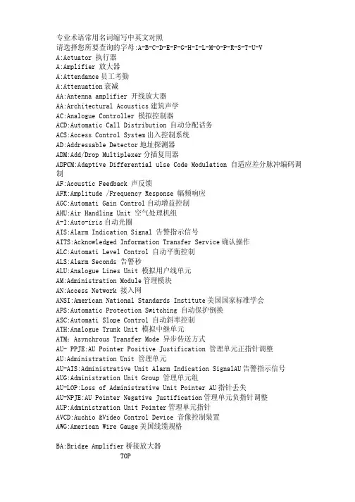
专业术语常用名词缩写中英文对照请选择您所要查询的字母:A-B-C-D-E-F-G-H-I-L-M-O-P-R-S-T-U-VA:Actuator 执行器A:Amplifier 放大器A:Attendance员工考勤A:Attenuation衰减AA:Antenna amplifier 开线放大器AA:Architectural Acoustics建筑声学AC:Analogue Controller 模拟控制器ACD:Automatic Call Distribution 自动分配话务ACS:Access Control System出入控制系统AD:Addressable Detector地址探测器ADM:Add/Drop Multiplexer分插复用器ADPCM:Adaptive Differential ulse Code Modulation 自适应差分脉冲编码调制AF:Acoustic Feedback 声反馈AFR:Amplitude /Frequency Response 幅频响应AGC:Automati Gain Control自动增益控制AHU:Air Handling Unit 空气处理机组A-I:Auto-iris自动光圈AIS:Alarm Indication Signal 告警指示信号AITS:Acknowledged Information Transfer Service确认操作ALC:Automati Level Control 自动平衡控制ALS:Alarm Seconds 告警秒ALU:Analogue Lines Unit 模拟用户线单元AM:Administration Module管理模块AN:Access Network 接入网ANSI:American National Standards Institute美国国家标准学会APS:Automatic Protection Switching 自动保护倒换ASC:Automati Slope Control 自动斜率控制ATH:Analogue Trunk Unit 模拟中继单元ATM:Asynchrous Transfer Mode 异步传送方式AU- PPJE:AU Pointer Positive Justification 管理单元正指针调整AU:Administration Unit 管理单元AU-AIS:Administrative Unit Alarm Indication SignalAU告警指示信号AUG:Administration Unit Group 管理单元组AU-LOP:Loss of Administrative Unit Pointer AU指针丢失AU-NPJE:AU Pointer Negative Justification管理单元负指针调整AUP:Administration Unit Pointer管理单元指针AVCD:Auchio &Video Control Device 音像控制装置AWG:American Wire Gauge美国线缆规格BA:Bridge Amplifier桥接放大器TOPBAC:Building Automation & Control net建筑物自动化和控制网络BAM:Background Administration Module后管理模块BBER:Background Block Error Ratio背景块误码比BCC:B-channel Connect ControlB通路连接控制BD:Building DistributorBEF:Buiding Entrance Facilities 建筑物入口设施BFOC:Bayonet Fibre Optic Connector大口式光纤连接器BGN:Background Noise背景噪声BGS: Background Sound 背景音响BIP-N:Bit Interleaved Parity N code 比特间插奇偶校验N位码B-ISDN:Brand band ISDN 宽带综合业务数字网B-ISDN:Broad band -Integrated Services Digital Network 宽带综合业务数字网BMC:Burst Mode Controller 突发模式控制器BMS:Building Management System 智能建筑管理系统BRI:Basic Rate ISDN 基本速率的综合业务数字网BS:Base Station基站BSC:Base Station Controller基站控制器BUL:Back up lighting备用照明C/S: Client/Server客户机/服务器TOPC:Combines 混合器C:Container 容器CA:Call Accounting电话自动计费系统CATV:Cable Television 有线电视CC:Call Control 呼叫控制CC:Coax cable 同轴电缆CCD:Charge coupled devices 电荷耦合器件CCF:Cluster Contril Function 簇控制功能CD:Campus Distributor 建筑群配线架CD:Combination detector 感温,感烟复合探测器CDCA:Continuous Dynamic Channel Assign 连续的动态信道分配CDDI:Copper Distributed Data 合同缆分布式数据接口CDES:Carbon dioxide extinguisbing system 二氧化碳系统CDMA:Code Division Multiplex Access 码分多址CF:Core Function 核心功能CFM:Compounded Frequency Modulation 压扩调频繁CIS:Call Information System 呼叫信息系统CISPR:Internation Special Conmittee On Radio Interference 国际无线电干扰专门委员会CLNP:Connectionless Network Protocol 无连接模式网络层协议CLP:Cell Loss Priority信元丢失优先权CM:Communication Module 通信模块CM:Configuration Management 配置管理CM:Cross-connect Matrix交叉连接矩阵CMI:Coded Mark Inversion传号反转码CMISE:Common Management Information Service公用管理信息协议服务单元CPE:Convergence protocol entity 会聚协议实体CR/E:card reader /Encoder (Ticket reader )卡读写器/编码器CRC:Cyclic Redundancy Check 循环冗佘校验CRT:Cathode Ray Tabe 显示器,监视器,阴极射线管CS: Convergence service 会聚服务CS:Cableron Spectrum 旧纳档块化技术CS:Ceiling Screen 挡烟垂壁CS:Convergence Sublayer合聚子层CSC:Combined Speaker Cabinet 组合音响CSCW:Computer supported collaborative work 计算机支持的协同工作CSES:Continuius Severely Errored Second 连续严重误码秒CSF:Cell Site Function 单基站功能控制CTB:Composite Triple Beat 复合三价差拍CTD:Cable Thermal Detector 缆式线型感温探测器CTNR:carrier to noise ratio 载波比CW:Control Word 控制字D:Directional 指向性TOPD:Distortion 失真度D:Distributive 分布式DA:Distribution Amplifier 分配的大器DBA:Database Administrator数据库管理者DBCSN:Database Control System Nucleus数据库控制系统核心DBOS:Database Organizing System 数据库组织系统DBSS:Database Security System 数据库安全系统DC:Door Contacts大门传感器DCC:Digital Communication Channel数字通信通路DCN:Data Communication Network 数据通信网DCP-I:Distributed Control Panel -Intelligent智能型分散控制器DCS:Distributed Control System集散型控制系统DDN:Digital Data Network 数字数据网DDS:Direct Dignital Controller直接数字控制器DDW:Data Describing Word 数据描述字DECT:Digital Enhanced Cordless Telecommunication增强数字无绳通讯DFB:Distributed Feedback 分布反馈DID:Direct Inward Dialing 直接中继方式,呼入直拨到分机用户DLC:Data Link Control Layer 数据链路层DLI:DECT Line InterfaceDODI:Direct Outward Dialing One 一次拨号音DPH:DECT PhoneDRC:Directional Response Cahracteristics 指向性响应DS:Direct Sound 直正声DSP:Digital signal Processing 数字信号处理DSS:Deiision Support System 决策支持系统DTMF:Dual Tone Multi-Frequency 双音多频DTS:Dual -Technology Sensor 双鉴传感器DWDM:Dense Wave-length Division Multiplexing 密集波分复用DXC:Digital Cross-Connect 数字交叉连接E:Emergency lighting照明设备TOPE:Equalizer 均衡器E:Expander 扩展器EA-DFB:Electricity Absorb-Distributed Feedback 电吸收分布反馈ECC:Embedded Control Channel 嵌入或控制通道EDFA:Erbium-Doped Fiber Amplifier掺饵光纤放大器EDI:Electronic Data Interexchange 电子数据交换EIC:Electrical Impedance Characteristics 电阻抗特性EMC:Electro Magnetic Compatibiloty 电磁兼容性EMI:Electro Magnetic Interference 电磁干扰EMS:Electromagnetic Sensitibility 电磁敏感性EN:Equivalent Noise 等效噪声EP:Emergency Power 应急电源ES:Emergency Sooket 应急插座ES:Evacuation Sigvial疏散照明ESA:Error SecondA 误码秒类型AESB:ErrorSecondB 误码秒类型BESD:Electrostatic Discharge静电放电ESR:Errored Second Ratio 误码秒比率ETDM:Electrical Time Division Multiplexing电时分复用ETSI:European Telecommunication Standards Institute欧洲电信标准协会F:Filter 滤波器TOPFAB:Fire Alarm Bell 火警警铃FACU:Fire Alarm Contrlol Unit 火灾自动报警控制装置FC:Failure Count 失效次数FC:Frequency Converter 频率变换器FCC:Fire Alarm System 火灾报警系统FCS:Field Control System 现场总线FCU:Favn Coil Unit风机盘管FD:Fire Door 防火门FD:Flame Detector 火焰探测器FD:Floor DistributorFD:Frequency Dirsder 分频器FDD:Frequency Division Dual 频分双工FDDI:Fiberdistributed Data Interface光纤缆分布式数据接口。
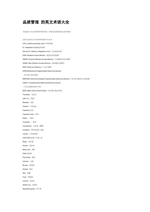
品质管理的英文术语大全从事品质工作以来积累的常用英语,希望对有需要的朋友有所帮助!品质专业英语大全零件材料类的专有名词CPU: central processing unit(中央处理器)IC: Integrated circuit(集成电路)Memory IC: Memory Integrated circuit(记忆集成电路)RAM: Random Access Memory(随机存取存储器)DRAM: Dynamic Random Access Memory(动态随机存取存储器)SRAM: Staic Random Access Memory(静态随机存储器)ROM: Read-only Memory(只读存储器)EPROM:Electrical Programmable Read-only Memory(电可抹只读存诸器)EEPROM: Electrical Erasbale Programmable Read-only Memory(电可抹可编程只读存储器)CMOS: Complementary Metal-Oxide-Semiconductor(互补金属氧化物半导体)BIOS: Basic Input Output System(基本输入输出系统)Transistor:电晶体LED:发光二极体Resistor:电阻Variator:可变电阻Capacitor:电容Capacitor array:排容Diode:二极体Transistor:三极体Transformer:变压器(ADP)Oscillator:频率振荡器(0sc)Crystal:石英振荡器XTAL/OSC:振荡产生器(X)Relay:延时器Sensor:感应器Bead core:磁珠Filter:滤波器Flat Cable:排线Inductor:电感Buzzer:蜂鸣器Socket:插座Slot:插槽Fuse:熔断器Current:电流表Solder iron:电烙铁Magnifying glass:放大镜Driver:螺丝起子Oven:烤箱TFT:液晶显示器Oscilloscope:示波器Connector:连接器PCB:printed circuit board(印刷电路板)PCBA: printed circuit board assembly(电路板成品)PP:并行接口HDD:硬盘FDD:软盘PSU:power supply unit(电源供应器)SPEC:规格Attach:附件Case: 机箱,盖子Cover:上盖Base:下盖Bazel:面板(panel)Bracket:支架,铁片Lable:贴纸Guide:手册Manual:手册,指南Card:网卡Switch:交换机Hub:集线器Router:路由器Sample:样品Gap:间隙Sponge:海绵Pallet:栈板Foam:保利龙Fiber:光纤Disk:磁盘片PROG:程序Barcode:条码System:系统System Barcode:系统条码M/B:mother board:主板CD-ROM:光驱FAN:风扇Cable:线材Audio:音效K/B:Keyboard(键盘)Mouse:鼠标Card reader:读卡器Screw:螺丝Thermal pad:散热垫Heat sink:散热片Rubber:橡胶垫Rubber foot:脚垫Bag:袋子Washer:垫圈Sleeve:袖套Config:机构Label hi-pot:高压标签Firmware label:烧录标签Metal cover:金属盖子Plastic cover:塑胶盖子Tape for packing:包装带Bar code:条码Tray:托盘Collecto:集线夹Holder:固定器,L铁Connecter:连接器IDE:集成电路设备,智能磁盘设备SCSI:小型计算机系统接口Gasket:导电泡棉AGP:加速图形接口PCI:周边组件扩展接口LAN:局域网USB:通用串形总线架构Slim:小型化COM:串型通讯端口LPT:打印口,并行口Power cord:电源线I/O:输入,输出Speaker:扬声器EPE:泡棉Carton:纸箱Button:按键,按钮Foot stand:脚架部门名称的专有名词QS:Quality system品质系统CS:Coutomer Sevice 客户服务QC:Quality control品质管理IQC:Incoming quality control 进料检验LQC:Line Quality Control 生产线品质控制IPQC:In process quality control 制程检验FQC:Final quality control 最终检验OQC:Outgoing quality control 出货检验QA:Quality assurance 品质保证SQA:Source(supplier) Quality Assurance 供应商品质保证(VQA) CQA:Customer Quality Assurance客户质量保证PQA rocess Quality Assurance 制程品质保证QE:Quality engineer 品质工程CE:component engineering零件工程EE:equipment engineering设备工程ME:manufacturing engineering制造工程TE:testing engineering测试工程PPE roduct Engineer 产品工程IE:Industrial engineer 工业工程ADM: Administration Department行政部RMA:客户退回维修CSDI:检修PC:producing control生管MC:mater control物管GAD: General Affairs Dept总务部A/D: Accountant /Finance Dept会计LAB: Laboratory实验室DOE:实验设计HR:人资PMC:企划RD:研发W/H:仓库SI:客验PD: Product Department生产部PA:采购(PUR: Purchaing Dept)SMT:Surface mount technology 表面粘着技术MFG:Manufacturing 制造MIS:Management information system 资迅管理系统DCC:document control center 文件管制中心厂内作业中的专有名词QT:Quality target品质目标QP:Quality policy目标方针QI:Quality improvement品质改善CRITICAL DEFECT:严重缺点(CR)MAJOR DEFECT:主要缺点(MA)MINOR DEFECT:次要缺点(MI)MAX:Maximum最大值MIN:Minimum最小值DIA iameter直径DIM imension尺寸LCL:Lower control limit管制下限UCL:Upper control limit管制上限EMI:电磁干扰ESD:静电防护EPA:静电保护区域ECN:工程变更ECO:Engineering change order工程改动要求(客户)ECR:工程变更需求单CPI:Continuous Process Improvement 连续工序改善Compatibility:兼容性Marking:标记DWG rawing图面Standardization:标准化Consensus:一致Code:代码ZD:Zero defect零缺点Tolerance:公差Subject matter:主要事项Auditor:审核员BOM:Bill of material物料清单Rework:重工ID:identification识别,鉴别,证明PILOT RUN: (试投产)FAI:首件检查FPIR:First Piece Inspection Report首件检查报告FAA:首件确认SPC:统计制程管制CP: capability index(准确度)CPK: capability index of process(制程能力)PMP:制程管理计划(生产管制计划)MPI:制程分析DAS efects Analysis System 缺陷分析系统PPB:十亿分之一Flux:助焊剂P/N:料号L/N:Lot Number批号Version:版本Quantity:数量Valid date:有效日期MIL-STD:Military-Standard军用标准ICT: In Circuit Test (线路测试)ATE:Automatic Test Equipment自动测试设备MO: Manafacture Order生产单T/U: Touch Up (锡面修补)I/N:手插件P/T:初测F/T: Function Test (功能测试-终测)AS 组立P/K:包装TQM:Total quality control全面品质管理MDA:manufacturing defect analysis制程不良分析(ICT)RUN-IN:老化实验HI-pot:高压测试FMI:Frequency Modulation Inspect高频测试DPPM: Defect Part Per Million(不良率的一种表达方式:百万分之一) 1000PPM即为0.1%Corrective Action: (CAR改善对策)ACC:允收REJ:拒收S/S:Sample size抽样检验样本大小SI-SIV:Special I-Special IV特殊抽样水平等级CON:Concession / Waive特采ISO:国际标准化组织ISA:Industry Standard Architecture工业标准体制结构OBA:开箱稽核FIFO:先进先出PDCA:管理循环Plan do check action计划,执行,检查,总结(计划,实施,检查,处置) WIP:在制品(半成品)S/O: Sales Order (业务订单)P/O: Purchase Order (采购订单)P/R: Purchase Request (请购单)AQL:acceptable quality level允收品质水准LQL;Limiting quality level最低品质水准QVL:qualified vendor list合格供应商名册AVL :认可的供货商清单(Approved Vendor List)QCD: Quality cost delivery(品质,交期,成本)MPM:Manufacturing project management制造专案管理KPI:Key performance indicate重要绩效指标MVT:Manufacturing Verification Test制造验证试产Q/R/S:Quality/Reliability/Service质量/可靠度/服务STL:ship to line(料到上线)NTF:No trouble found误判CIP:capacity improvement plan(产能改善计划)MRB:material review board(物料审核小组)MRB:Material reject bill退货单JIT:just in time(即时管理)5S:seiri seiton seiso seiketsu shitsuke(整理,整顿,清扫,清洁,修养)SOP:standard operation process(标准作业程序)SIP:Specification inspection process制程检验规格TOP: Test Operation Process (测试作业流程)WI: working instruction(作业指导书)SMD:surface mounting device(表面粘着原件)FAR:failure aualysis report故障分析报告CAR:Corrective action report改善报告BPR:企业流程再造(Business Process Reengineering)ISAR :首批样品认可(Initial Sample Approval Request)-JIT:实时管理(Just In Time)QCC :品管圈(Quality Control Circle)Engineering Department (工程部)TQEM: Total Quality Environment Management(全面品质环境管理)PD: Production Department (制造)LOG: Logistics (后勤支持)Shipping: (进出口)AOQ:Average Output Quality平均出货质量AOQL:Average Output Quality Level平均出货质量水平FMEA:failure model effectiveness analysis失效模式分析CRB: Change Review Board (工程变更会议)CSA:Customer Simulate Analysis客户模拟分析SQMS:Supplier Quality Management System供应商品质管理系统QIT: Quality Improvement Team 品质改善小组QIP:Quality Improvement Plan品质改善计划CIP:Continual Improvement Plan持续改善计划M.Q.F.S: Material Quality Feedback Sheet (来料品质回馈单)SCAR: Supplier Corrective Action Report (供货商改善对策报告)8D Sheet: 8 Disciplines sheet ( 8D单)小组成立问题说明实施并验证临时措施确定并验证根本原因选择并验证永久纠正措施实施永久纠正措施预防再发生小组祝贺PDCA:PDCA (Plan-Do-Check-Action) (管理循环)MPQ: Material Packing Quantity (物料最小包装量)DSCN: Delivery Schedule Change Notice (交期变更通知)QAPS: Quality Assurance Process Sheet (品质工程表)DRP :运销资源计划(Distribution Resource Planning)DSS:决策支持系统(Decision Support System)EC :电子商务(Electronic Commerce)EDI :电子资料交换(Electronic Data Interchange)EIS :主管决策系统(Excutive Information System)ERP:企业资源规划(Enterprise Resource Planning)FMS :弹性制造系统(Flexible Manufacture System)KM :知识管理(Knowledge Management)4L :逐批订购法(Lot-for-Lot)LTC :最小总成本法(Least Total Cost)LUC :最小单位成本(Least Unit Cost)MES :制造执行系统(Manufacturing Execution System) MPS :主生产排程(Master Production Schedule)MRP :物料需求规划(Material Requirement Planning) MRPⅡ:制造资源计划(Manufacturing Resource Planning) OEM :委托代工(Original Equipment Manufacture)ODM :委托设计与制造(Original Design & Manufacture) OLAP:线上分析处理(On-Line Analytical Processing) OLTP:线上交易处理(On-Line Transaction Processing) OPT :最佳生产技术(Optimized Production Technology) PDCA:PDCA管理循环(Plan-Do-Check-Action)PDM:产品数据管理系统(Product Data Management)) RCCP:粗略产能规划(Rough Cut Capacity Planning) SCM :供应链管理(Supply Chain Management)SFC :现场控制(Shop Floor Control)TOC:限制理论(Theory of Constraints)TQC :全面品质管制(Total Quality Control)FYI/R:for your information/reference仅供参考ASAP:尽快S/T:Standard time标准时间TPM:total production maintenance:全面生产保养ESD Wrist strap:静电环IT:information technology信息技术,资讯科学CEO:Chief Executive Officer执行总裁COO:Chief Operaring Officer首席业务总裁SWOT:Strength,Weakness,Opportunity,Threat优势﹐弱点﹐机会﹐威胁Competence:专业能力Communication:有效沟通Cooperation:统御融合Vibration Testing:振动测试IDP:Individual Development Plan个人发展计划MRP:Material Requirement Planning物料需求计划MAT'S:Material材料LRR:Lot Rejeet Rate批退率ATIN:Attention知会3C:Computer ,Communication , Consumer electronic消费性电子5W1H:When , Where , Who , What , Why , Ho5M: Man , Machine , Material , Method , Measurement人,机器,材料,方法,测量4MIE: Man,Material,Machine,Method,Environment人力,物力,财务,技术,时间(资源)7M1I: Manpower , Machine , Material , Method, Market , Management , Money , Information 人力,机器,材料,方法, 市场,管理,资金,资讯1 Accuracy 准确度2 Action 行动3 Activity 活动4 Analysis Covariance 协方差分析5 Analysis of Variance 方差分析6 Approved 承认7 Attribute 计数值8 Average 平均数9 Balance sheet 资产负债对照表10 Binomial 二项分配11 Brainstorming Techniques 脑力风暴法12 Cause and Effect Matrix 因果图(鱼骨图)13 CL:Center Line 中心线14 Check Sheets 检查表15 Complaint 投诉16 Conformity 合格(符合)17 Control 控制18 Control chart 控制(管制)图19 Correction 纠正20 Correlation Methods 相关分析法21 CPI: continuouse Process Improvement 连续工序改善22 Cross Tabulation Tables 交叉表23 CS: Customer Sevice 客(户)服(务)中心24 DSA: Defects Analysis System 缺陷分析系统25 Data 数据Description:品名26 DCC: Document Control Center 文控中心27 Decision 决策、判定28 Defects per unit 单位缺点数29 Description 描述30 Device 装置31 Do 执行32 DOE: Design of Experiments 实验设计33 Element 元素34 Engineering recbnology 工程技35 Environmental 环境36 Equipment 设备37 Estimated accumulative frequency 计算估计累计数38 E Equipment Variation 设备变异39 External Failure 外部失效,外部缺陷40 FA: Failure Analysis 失效分析41 Fact control 事实管理42 Fatigue 疲劳43 FMEA: Failure Mode and Effect Analysis失效模式与效果分析44 FP First-Pass Yield (第一次通过)合格率45 FQA: Final Quality Assurance 最终品质保证46 FQC: Final Quality control 最终品质控制47 Gauge system 测量系统48 Grade 等级49 Histogram 直方图50 Improvement 改善51 Initial review 先期审查52 Inspection 检验53 Internal Failure 内部失效、内部缺陷54 IPQC: In Process Quality Control 制程品质控制55 IQC: Incomming Quality Control 来料品质控制56 IS International Organization for Standardization 国际标准化组织57 LCL: Lower Control limit 管制下限58 LQC: Line Quality Control 生产线品质控制59 LSL: Lower Size Limit 规格下限60 Machine 机械61 Manage 管理62 Materials 物料63 Measurement 测量64 Median 中位数65 MSA: Measurement System Analysis 测量系统分析66 Occurrence 发生率67 Operation Instruction 作业指导书68 Organization 组织69 Parto 柏拉图70 PPM arts per Million (百万分之)不良率71 Plan 计划72 Policy 方针73 Population 群体74 PQA: Process Quality Assurance 制程品质保证75 Practice 实务(践)76 Prevention 预防77 Probability 机率78 Probability density function 机率密度函数79 Procedure 流程80 Process 过程81 Process capability analysis 制程能力分析(图)82 Process control and Process capability制程管制与制程能力83 Product 产品84 Production 生产85 Projects 项目86 QA: Quality Assurance 品质保证87 QC: Quality Control 品质控制88 QE: Quality Engineering 品质工程89 QFD: Quality Function Desgin 品质机能展开(法)90 Quality 质量91 Quality manual 品质手册92 Quality policy 品质政策(质量方针)93 Random experiment 随机试验94 Random numbers 随机数95 R:Range 全距(极差)96 Reject 拒收97 Repair 返修98 Repeatusility 再现性99 Reproducibility 再生性100 Requirement 要求101 Responsibilities 职责102 Review 评审103 Reword 返工104 Rolled yield 直通率105 RPN: Risk Priority Number 风险系数106 Sample 抽样,样本107 Sample space 样本空间108 Sampling with replacement 放回抽样109 Sampling without replacement 不放回抽样110 Scatter diagram 散布图分析111 Scrap 报废112 Simple random sampling 简单随机取样113 Size 规格114 SL: Size Line 规格中心线115 Stratified random sampling 分层随机抽样116 SOP: Standard Operation Procedure 标准作业书117 SPC: Statistical Process Control 统计制程管制118 Specification 规范119 SQA: Source(Supplier) Quality Assurance 供货商品质保证120 Stage sampling 分段随机抽样121 Standard Deviation 标准差122 Sum of squares 平方和123 Taguchi-method 田口(试验)方法124 Theory 原理125 TQC: Total Quality Control 全面品质控制126 TQM: Total Quality Management 全面品质管理127 Traceablity 追溯128 Training 培训129 UCL: Upper Control Limit 管制(控制)上限130 USL: Upper Size Limit 规格上限131 Validation 确认132 Variable 计量值133 Verification 验证134 Version 版本135 VOC: Voice of Customer 客户需求136 VOE: Voice of Engineer 工程需求137 Inventory stock report:庫存清单报告138 Sales order report:出货报告质量人员名称类QC quality control 品质管理人员FQC final quality control 终点质量管理人员IPQC in process quality control 制程中的质量管理人员OQC output quality control 最终出货质量管理人员IQC incoming quality control 进料质量管理人员TQC total quality control 全面质量管理POC passage quality control 段检人员QA quality assurance 质量保证人员OQA output quality assurance 出货质量保证人员QE quality engineering 质量工程人员质量保证类FAI first article inspection 新品首件检查FAA first article assurance 首件确认CP capability index 能力指数CPK capability process index 模具制程能力参数SSQA standardized supplier quality audit 合格供货商质量评估FMEA failure model effectiveness analysis 失效模式分析FQC运作类AQL Acceptable Quality Level 运作类允收质量水平S/S Sample size 抽样检验样本大小ACC Accept 允收REE Reject 拒收CR Critical 极严重的MAJ Major 主要的MIN Minor 轻微的Q/R/S Quality/Reliability/Service 质量/可靠度/服务P/N Part Number 料号L/N Lot Number 批号AOD Accept On Deviation 特采UAI Use As It 特采FPIR First Piece Inspection Report 首件检查报告PPM Percent Per Million 百万分之一制程统计品管专类SPC Statistical Process Control 统计制程管制SQC Statistical Quality Control 统计质量管理GRR Gauge Reproductiveness & Repeatability 量具之再制性及重测性判断量可靠与否DIM Dimension 尺寸DIA Diameter 直径N Number 样品数其它质量术语类QIT Quality Improvement Team 质量改善小组ZD Zero Defect 零缺点QI Quality Improvement 质量改善QP Quality Policy 目标方针TQM Total Quality Management 全面质量管理RMA Return Material Audit 退料认可7QCTools 7 Quality Control Tools 品管七大手法通用之件类ECN Engineering Change Notice 工程变更通知(供货商)ECO Engineering Change Order 工程改动要求(客户)PCN Process Change Notice 工序改动通知PMP Product Management Plan 生产管制计划SIP Standard Inspection Procedure 制程检验标准程序SOP Standard Operation Procedure 制造作业规范IS Inspection Specification 成品检验规范BOM Bill Of Material 物料清单PS Package Specification 包装规范SPEC Specification 规格DWG Drawing 图面系统文件类ES Engineering Standard 工程标准CGOO China General PCE龙华厂文件IWS International Workman Standard 工艺标准ISO International Standard Organization 国际标准化组织GS General Specification 一般规格部类PMC Production & Material Control 生产和物料控制PCC Product control center 生产管制中心PPC Production Plan Control 生产计划控制MC Material Control 物料控制DC Document Center 资料中心QE Quality Engineering 质量工程(部)QA Quality Assurance 质量保证(处)QC Quality Control 质量管理(课)PD Product Department 生产部LAB Laboratory 实验室IE Industrial Engineering 工业工程R&D Research & Design 设计开发部生产类PCs Pieces 个(根,块等)PRS Pairs 双(对等)CTN Carton 卡通箱PAL Pallet/skid 栈板PO Purchasing Order 采购订单MO Manufacture Order 生产单D/C Date Code 生产日期码ID/C Identification Code (供货商)识别码SWR Special Work Request 特殊工作需求L/N Lot Number 批号P/N Part Number 料号OEM Original Equipment Manufacture 原设备制造PC Personal Computer 个人计算机CPU Central Processing Unit 中央处理器A.S.A.P As Soon As Possible 尽可能快的E-MAIL Electrical-Mail 电子邮件N/A Not Applicable 不适用QTY Quantity 数量I/O input/output 输入/输出NG Not Good 不行,不合格C=0 Critical=0 极严重不允许APP Approve 核准,认可,承认CHK Check 确认ASS'Y Assembly 装配,组装T/P True Position 真位度5WIH When, Where, Who, What, Why, How to6M Man, Machine, Material, Method, Measurement, Message4MTH Man, Material, Money, Method, Time, How 人力,物力,财务,技术,时间(资源) SQA Strategy Quality Assurance 策略质量保证DQA Design Quality Assurance 设计质量保证MQA Manufacture Quality Assurance 制造质量保证SSQA Sales and service Quality Assurance 销售及服务质量保证LRR Lot Reject Rate 批退率SPS Switching power supply 电源箱DT Desk Top 卧式(机箱)MT Mini-Tower 立式(机箱)DVD Digital Video DiskVCD Video Compact DiskLCD Liquid Crystal DisplayCAD Computer Aided DesignCAM Computer Aided ManufacturingCAE Computer Aided EngineeringPCB Printed Circuit Board 印刷电路板CAR Correction Action Report 改善报告NG Not Good 不良WDR Weekly Delivery Requirement 周出货要求PPM Percent Per Million 百万分之一TPM Total Production Maintenance 全面生产保养MRP Material Requirement Planning 物料需计划OS Operation System 操作系统TBA To Be Assured 待定,定缺D/C Drawing ChangeP/P Plans & ProcedureEMI Electrical-Music Industry 电子音乐工业Electrical Magnetic Interference 电子干扰RFI Read Frequency Input 读频输入MMC Maximum Material ConditionMMS Maximum Material SizeLMC Least Material ConditionLMS Least Material SizeLED lighting-emitting diode 发光二极管QBR Quarter Business RecordCIP Continuous improvement processFGI Forecasted Goal InventoryCNC Computerized numeral controllerB2C Business to customerB2B Business to businessAVL Approved vendor listPOP Procedure of packagingEOL End of lifeVDCS Vender defect correcting sheetPDCS Process defect correcting sheetGRN Goods receiving noteA/R Accounting receivableA/P Accounting payable专业词汇通用类president董事长operator作业员position职务general manager总经理special assistant 特助deputy manager |'depjuti| =vice manager副理deputy supervisor =vice supervisor副课长group leader组长line leader线长supervisor 课长responsible department负责单位Human Resources Department人力资源部Head count 人头数production department生产部门planning department企划部QC Section品管课stamping factory冲压厂painting factory烤漆厂molding factory成型厂administration/general affairs dept./总务部production unit生产单位meeting minutes会议记录distribution department分发单位subject主题conclusion结论decision items决议事项pre-fixed finishing date预定完成日Color management 颜色管理Visual management 目视管理production capacity生产力first count初盘first check初盘复棹second count 复盘second check复盘复核quantity of physical inventory second count 复盘点数量physical inventory盘点数量physical count quantity账面数量difference quantity差异量spare parts physical inventory list备品盘点清单cause analysis原因分析waste materials废料description品名specification 规格model机种work order工令revision版次remark备注registration登记registration card登记卡to control管制application form for purchase请购单consume, consumption消耗to notify通知to fill in填写to collect, to gather收集statistics统计cosmetic inspection standard 外观检验规范computer case 计算机外壳(组件)personal computer enclosure 计算机机箱产品front plate前板rear plate后板chassis |'∫æsi| 基座bezel panel面板Hood 上盖base pan 基座bezel 面板riser card 扩充卡flat cable 排线TOP driver cage 上磁架bottom driver cage 下磁架resin film 树脂膜raw materials原料materials物料steel plate钢板roll/coil material卷料spare parts =buffer备品plastic parts塑料件sheet metal parts/stamping parts 冲件material check list物料检查表finished product成品semi-finished product半成品good product/accepted goods/ accepted parts/good parts良品defective product/non-good parts不良品disposed goods处理品warehouse/hub仓库packing material包材basket蝴蝶竺plastic basket胶筐flow chart流程窗体production tempo生产进度现状lots of production生产批量manufacture procedure制程to revise, modify修订to switch over to, switch—to, switching over切换engineering bottleneck, project difficulty工程瓶颈glove(s)手套glove(s) with exposed fingers割手套Band-Aid创可贴Industrial alcohol工业酒精broom扫把mop拖把vacuum cleaner吸尘器rag 抹布garbage container灰箕garbage can垃圾箱garbage bag垃圾袋liaison联络单rags抹布lamp holder灯架to mop the floor拖地to clean a table擦桌子air pipe 气管delivery deadline交货期die worker模工production, to produce生产equipment设备resistance电阻beacon警示灯coolant冷却液crusher破碎机club car高尔夫球车plate电镀power button电源按键reset button重置键forklift叉车Workshop traveler 天车trailer =long vehicle拖板车Hydraulic trolley手压车hydraulic hand jack油压板车casing = containerization装箱velocity速度patent专利coordinate坐标supply and demand供求career card履历卡barricade隔板carton box纸箱to pull and stretch拉深work cell/work shop工作间sub-line支线bottleneck 瓶颈模具工程类plain die简易模pierce die冲孔模forming die成型模progressive die连续模stage die工程模compound die复合模shearing die剪边模riveting die铆合模feature die公母模male die公模female die母模cavity型控母模core模心公模die change 换模to fix a die装模to repair a die修模punch set上模座punch pad上垫板punch holder上夹板stripper pad脱料背板up stripper上脱料板upper plate上模板lower plate下模板die pad下垫板die holder下夹板die set下模座bottom block下垫脚bottom plate下托板(底板)upper supporting blank上承板upper padding plate blank上垫板top plate上托板(顶板)top block上垫脚stripping plate内外打(脱料板)outer stripper外脱料板inner stripper内脱料板lower stripper下脱料板punch冲头insert入块(嵌入件)deburring punch压毛边冲子groove punch压线冲子stamped punch字模冲子round punch圆冲子special shape punch异形冲子bending block折刀roller滚轴baffle plate挡块located block定位块supporting block for location定位支承块air cushion plate气垫板air-cushion eject-rod气垫顶杆trimming punch切边冲子stiffening rib punch = stinger 加强筋冲子ribbon punch压筋冲子reel-stretch punch卷圆压平冲子guide plate定位板sliding block滑块sliding dowel block滑块固定块die locker锁模器pressure plate =plate pinch压板thickness gauge厚薄规cutting die, blanking die冲裁模die block模块folded block折弯块sliding block滑块location pin定位销lifting pin顶料销die plate, front board模板padding block垫块stepping bar垫条panel board镶块to load a die装上模具to unload a die 御模具active plate活动板lower sliding plate下滑块板upper holder block上压块upper mid plate上中间板spring box弹簧箱spring-box eject-rod弹簧箱顶杆spring-box eject-plate弹簧箱顶板bushing block衬套cover plate盖板guide pad导料块pilot导正筒trim剪外边pierce剪内边pocket for the punch head挂钩槽slug hole废料孔radius半径shim/wedge/heel/pad/spacer/gasket楔子torch-flame cut火焰切割set screw止付螺丝form block折刀round pierce punch =die button圆冲子shape punch =die insert异形子stock located block定位块metal plate钣金miller铣床grinder磨床tolerance公差score =groove压线sliding block滑块lathe车active plate活动板baffle plate挡块cover plate盖板groove punch压线冲子air-cushion eject-rod气垫顶杆spring-box eject-plate弹簧箱顶板capability能力parameter参数factor系数driller钻床set up die架模height of die setting up架模高度analog-mode device类模器inner guiding post内导柱inner hexagon screw内六角螺钉dowel pin固定销coil spring弹簧lifter pin顶料销eq-height sleeves =spool等高套筒pin销lifter guide pin浮升导料销guide pin导正销wire spring圆线弹簧outer guiding post外导柱stop screw止付螺丝located pin定位销outer bush外导套press specification冲床规格die height闭模高度flow mark流痕welding mark溶合痕post screw insert螺纹套筒埋值self tapping screw自攻螺丝stripper plate脱料板piston活塞handle mold手持式模具flash mold溢流式模具positive mold挤压式模具split mold分割式模具die lifter举模器top stop上死点bottom stop下死点one stroke一行程to continue, cont.连动to grip(material)吸料location lump, locating piece, location block定位块reset复位to file burr 锉毛刺embedded lump |in'bed| mp|镶块 |lstamping-missing漏冲to tight a bolt拧紧螺栓to loosen a bolt拧松螺栓punched hole冲孔to cut edge =side cut =side scrap 切边to bending折弯to pull, to stretch拉伸engraving, to engrave刻印stamping 油印to stake铆合designing, to design设计design modification 设计修改成gauge(or jig)治具pedal踩踏板stopper阻挡器flow board流水板torque扭矩spline =the multiple keys花键quenching淬火tempering回火annealing退火carbonization碳化alloy合金tungsten high speed steel钨高速的moly high speed steel钼高速的forming成型(抽凸,冲凸)draw hole抽孔bending折弯emboss凸点dome凸圆semi-shearing半剪stamp mark冲记号deburr or coin压毛边punch riveting冲压铆合side stretch侧冲压平reel stretch卷圆压平groove压线stamp letter冲字(料号)tick-mark nearside正面压印tick-mark farside反面压印冲压类punch, press冲punching machine 冲床hydraulic machine油压机jack升降机decoiler整平机manufacture management制造管理stamping, press冲压feeder送料机rack, shelf, stack料架taker取料机to reverse material 翻料to load material上料to unload material卸料to return material/stock to退料scraped |'skræpid|报废scrape ..v.刮;削robot机械手production line流水线packaging tool打包机packaging打包成型类well type蓄料井insulated runner绝缘浇道方式hot runner热浇道runner plat浇道模块valve gate阀门浇口band heater环带状的电热器spindle阀针spear head刨尖头slag well冷料井cold slag冷料渣air vent排气道welding line熔合痕eject pin顶出针knock pin顶出销return pin回位销反顶针sleeve套筒stripper plate脱料板insert core放置入子runner stripper plate浇道脱料板guide pin导销eject rod (bar)(成型机)顶业捧subzero深冷处理three plate三极式模具runner system浇道系统stress crack应力电裂orientation定向sprue gate射料浇口,直浇口nozzle射嘴sprue lock pin料头钩销(拉料杆) slag well冷料井side gate侧浇口edge gate侧缘浇口tab gate搭接浇口flash gate闸门浇口slit gate缝隙浇口fan gate扇形浇口dish gate因盘形浇口diaphragm gate隔膜浇口ring gate环形浇口submarine gate潜入式浇口tunnel gate隧道式浇口pin gate针点浇口runner less无浇道sprue less 无射料管方式long nozzle延长喷嘴方式spur浇口;溶waste废料board广告牌sliding rack滑料架to impose lines压线to compress, compressing压缩character die字模to feed, feeding送料material change, stock change材料变更feature change 特性变更prepare for, make preparations for 准备rotating speed, revolution转速abnormal handling异常处理组装类Assembly line组装线Layout布置图Conveyer流水线运输带Rivet machine拉钉机Rivet gun拉钉枪Screw driver起子Electric screw driver电动起子Hydraulic machine 液压机Pneumatic screw driver气动起子automation自动化to stake, staking, riveting铆合add lubricant oil加润滑油argon welding氩焊cylinder油缸robot机械手transmission rack输送架to draw holes抽孔bolt螺栓nut 螺母screw 螺丝identification tag标示单screwdriver plug起子插座automatic screwdriver电动启子to move, to carry, to handle搬运be put in storage入库packing包装staker = riveting machine铆合机fit together组装在一起fasten锁紧(螺丝)fixture 夹具(治具)pallet/skid栈板barcode条形码barcode scanner条形码扫描仪fuse together熔合fuse machine/heat stake热熔机processing, to process加工delivery, to deliver 交货to return delivery to. to send delivery back to return of goods退货easily damaged parts易损件standard parts标准件to lubricate润滑spring 弹簧spare tools location/buffer手工备品仓spare molds location模具备品仓tox machine自铆机烤漆类phosphate皮膜化成viscosity涂料粘度alkalidipping脱脂main manifold主集流脉organic solvent有机溶剂demagnetization去磁;消磁high-speed transmission高速传递heat dissipation热传rack上料volatile挥发性degrease脱脂rinse水洗alkaline etch龄咬desmot剥黑膜D.I. rinse纯水次Chromate铬酸处理Anodize阳性处理seal封孔scraped products报放品disposed products处理品dismantle the die折模auxiliary function辅助功能heater band 加热片thermocouple热电偶derusting machine除锈机degate打浇口dryer烘干机induction感应induction light感应光response =reaction =interaction感应ram连杆edge finder巡边器concave凸convex凹cold slug冷块blush 导色gouge沟槽;凿槽satin texture段面咬花witness line证示线grit沙砾granule =pellet =grain细粒sand blasting喷沙grit maker抽粒机cushion缓冲fillet镶;嵌边roller pin formality滚针形式cam driver铡楔shank摸柄crank shaft曲柄轴品质类qualified products, up-to-grade products良品defective products, not up-to-grade products不良品。
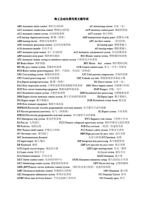
热工自动化常用英文缩写词ABC Automatic boiler control 锅炉自动控制AC Alternating current 交流(电)ACC Automatic combustion control 燃烧自动控制ACP Auxiliary control panel 辅助控制盘ACS Automatic control system 自动控制系统ACT actuator 执行机构A/D Analog /digital(conversion) 模/数(转换)ADP Annunciation display panel 报警显示板AEH Analog electro- 模拟式电液调节AFC Air flow control `送风控制AGC Automatic generation control 自动发电量控制AI Analog input 模拟量输入A/M Automatic/manful 自动/手动AO Analog output 模拟量输入APC Automatic plant control 电厂自动控制ASS Automatic synchronized system 自动同期系统ARP Auxiliary relay panel 辅助继电器盘BCS Burner control system 燃烧器控制系统ATC Automatic turbine startup or shutdown control system 汽轮机自启停系统BF Boiler follow 锅炉跟踪BFC Boiler fuel control 锅炉燃料控制BPS By-pass control system 旁路控制系统CCR Central control room 单元(中央)控制室BTG Boiler turbine generator(panel) 锅炉、汽轮机、发电机(控制盘)CHS Coal handing system 输煤控制系统CJC Cold junction compensator 冷端补偿器CPU Central processing unit 中央处理器CRT Cathode-ray tube 阴极射线管屏幕显示器D/A Digital/analog(conversion) 数/模(转换)DC Direct current 直流(电)DAS Data acquisition system 计算机监视系统或数据采集系统DDC Direct digital control 直接数字控制DCE Data circuit-terminating equipment 数据电路终端设备DMP Damper 挡板、风门DCS Distributed control system 分散控制系统DDP Distributed data processing 分散数据处理DEH Digital electro-hydraulic control system 数字式电液控制系统DI Digital input 数字量输入DO Digital output 数字量输出DSB Distributed switch-board 配电盘DTE Data terminal equipment 数据中端设备EEPROM Electrically-erasable programmable read only memory 电可擦写只读存储器E/P Electro/pneumatic(converter) 电/气(转换器)ES Expert system 专家系统EPROM Electrically programmable read only memory 电可编程只读存储器ETS Emergency trip system 紧急停机系统EWS Engineer wok station 工程师工作站FA Full arc 全周进汽FSSS Furnace safeguard supervisory system 锅炉炉膛安全监控系统FB Field bus 现场总线FCB Fast cut back (机组)快速甩负荷FDC Furnace draft control 炉膛压力控制FSS Furnace safety system 炉膛安全系统GV Governor valve 调节阀门HBP High-pressure by-pass valve 高压旁路I&C Instrumentation &control 仪表与控制INT Interlock 连锁I/O Input/output 输入/输出IDP Integrated data processing 集中数据处理KB Keyboard 键盘LBP Low-pressure by-pass valve 低压旁路LCD Liquid-crystal display 液晶显示器LED Light emitting diode 发光二极管LS Limit switch 限位开关LS Level switch 液位开关M/A Manual/automatic 手动/自动MAX Maximum 最大值MCC Motor control center 电动机控制中心MCR Maximum continuous rating 最大连续运行负荷MCS Modulating control system 模拟量控制系统MFT Master fuel trip 总燃料跳闸MEH (BFTP)micro-electro-hydraulic control system (锅炉给水泵汽轮机)电液控制系统MHC Mechanical hydraulic control 机械液压式控制MIN Minimum 最小值MIS Management information system 管理信息系统NC Normally Closed 常闭MTBF Mean time between failures 平均无故障工作时间NO Normally open 常开MTTF Mean time to failure 失效(故障)前平均工作时间OEI Optic electric interface 光电接口MTTR Mean time to repair 平均故障修复时间OCS On-off control system 开关量控制系统OFT Oil fuel trip 燃油跳闸OPC Overspend protection CONTROL 超速保护控制OS Operator station 操作员站PA Partial arc 部分进汽PC Programmable controller 可编程控制器PCS Pulverize control system 磨煤机控制系统PI Purse input 脉冲量输入PID Proportional integral derivative 比例-积分-微分PLC Programmable logic controller 可编程序逻辑控制器PO Pulse output 脉冲量输出RAM Random access memory随机存取存储器RB Run back (辅机故障)快速甩负荷ROM Read only memory 只读存储器RTC Reheat steam temperature control 再热气温控制SBC Soot blower control system 吹灰控制系统SCM Single chip microcomputer 单片机SCS Sequence control system 顺序控制系统SER Sequence events recorder 事件顺序记录仪SOE Sequence of events 事件顺序记录ST Smart transmitter 智能变送器STC Superheated steam temperature control 过热气温控制TF Turbine follow 汽轮机跟踪TAS Turbine automatic system 汽轮机自动控制系统TBP Turbine by-pass system 汽轮机旁路系统TCS Turbine control system 汽轮机控制系统TSI Turbine supervisory instrument 汽轮机监视仪表UCC Unit coordinated control 机组协调控制ULD Unit load demand(command) 机组负荷指令UPS Uninterrupted power system 不间断电源WTS Water treatment contra system 水处理控制系统电厂设备用英语acid cleaning 酸洗interstate leakage 级间漏汽coal bunker 原煤斗intervention/disturbing/bump 扰动excess air 过量空气inverter 转换开关induced draft fan 引风机isolate 相互隔离steam drum 汽包item 物品、元件sub-distribution transformer低压厂用变journal bearing 支持轴承6kv station board 6KV公用配电屏6kv unit board 6KV配电屏kilo-volt 千伏low pressure cylinder/casing(LP) 低压缸A: ampere 安培adapter 转接器、接头、large scale integrate circuit 大规模集成电路actuator 执行机构LED 发光二极管light/ignite 点火air circuit breaker 空气断路器air dry 分析基linear variable differential transformer (LVDT) 线性差动变压器linearization 线性化air preheated 空气预热器liquid 液态air-insulated 空气绝缘的live steam 主蒸汽algorithms 算法load tap-changing 有载调压的alignment 平直度log 记录、日志alteration 改造longitudinal 纵向的alternating current 交流电lug 吊耳ammonia 氨major pant item 主要辅机amplitude 幅度making current 关合电流analogue 模拟量malfunction 误动作Analogue to Digital conversion 模数转换mechanism 操作机构annex 附属部分medium 媒介、介质annular 环状的membrane panel/wall 膜式壁enunciator 报警器micro governor 微型调速器anthracite 无烟煤mill 铁素体apex 顶点mill volt 毫伏archive buffer 文件缓冲器Mimic 模拟图armature 电枢MMC: motor control center 电动机控制中心ash 灰分as received 应用基Modulation 调节、调制modulation-demodulation 调制解调ASM 模拟子模块moisture 水分Temperature 减温器monitor mode 监控方式Automatic Boiler Controls 锅炉自动控制monitoring 监测monitor/monitor unit 监控器monoxide 一氧化碳autonomous 独立存在的automatic control system 自动控制系统auxiliary 辅助的axial 轴向的motor starter 电动机启动装置motor-operated 电动操纵的back-up 备用moving blades/ balding 动叶片bar 条形multiform root 叉型叶根barograph 条形图Multi Function Process(MFP) 多功能处理器natural gas 天然气batch 成组的、成批的MVA: mega volt-ampere 兆伏安baud rate 波特率bay 隔间natural/thermal circulation 自然循环bearing house 轴承座network 电网bearing pad 轴瓦neutral point 中性点binary 二进制的nitrogen 氮binary cell 二进制单元node 节点binary counter 二进制计数器notch V形凹槽bit 比特、位ohm 欧姆bituminous 烟煤oil 石油blank 毛胚open loop 开环blow/purge 吹扫open-cycle 开环lowdown pipe 排污管operation 运行/操作boil 沸腾operation condition 运行工况boiler/steam generator 锅炉optimum control 最优控制Boil out 煮炉order polynomial 多项式breaking current 开断电流orientation 定位brown coal/lignite 褐煤outage 停运bubble 汽泡outdoor 户外的burner 燃烧器outer casing 外缸bus interface module(BIM) 总线接口模块overhaul 大修bulbar/bus 母线overhead 架空的cable 电缆overhead transmission line 架空输电线calibration 检验overview 全貌、总的看法capacitance 电容oxidized condition/atmosphere 氧化气氛oxygen 氧capacitive current 电容电流capacitor 电容器palm terminal 星型capacity 容量panel 配电盘、屏、板carbon 碳parallel interface 并行接口cast resin transformer 树脂浇注变压器pedestal 轴承座casting 锻造pedestal 轴承座centerline 中心线peer 同类的central control room (CCR) 集控室permanent 长久的channel 通道、信道permanent magnet 永久磁铁character 符号字符permeability 磁导率charger 充电器PF burner/pulverized fuel burner 煤粉燃烧器circular 圆形的chronological 按时间顺序的phase change 相变circuit breaker 断路器photo-electric 光电pick-ups 采样器circumferential 周围的pipe 管道pilot exciter 副励磁机clearance 间隙closed loop 闭环plane 平面coal 煤plant-loop 厂环coal feeder 给煤机pneumatic pilot valve 启动控制阀coil 线圈power plant 电厂cold junction compensation 冷端补偿collar 轴环power station (水)电站power supplies 电源Commission 试运行pressure 压力commissioning operation 试运行pressure meter 压力表pressure firing 正压燃烧common service system 公用系统compatibility 兼容性、相容性probe 探针compatible 能共存的、兼容的Process Control Unit (PCU) 过程处理单元complete functional set 全功能组件condensate 凝结concentricity 中心度、同心度conductance 导纳programmable logic controller(PLC) 可编程逻辑控制器prolong outage 长期停机programmable read only memory(PROM) 可编程只读存储器conductor 导体conductibility 电导率provision 备用proximate analysis 工业分析protection and trip 保护和跳闸cone 锥体configure 组态PT: potential /voltage transformer 电压互感器pulverize/mill 磨煤机conical 圆锥形的push button 按钮connected in star 星型连接push contact 按钮触点consumption 消耗pushbutton 按钮control accuracy 控制精度pyramid 锥体control action 控制作用quality 质量control and instrumentation(C&I) 控制仪表系统quench 灭弧control button(knob) 控制按钮radial 半径的、辐射状的control console(desk) 控制台controller 控制器Rotor 转子reactance 电抗convection pass 对流烟道coupling 联轴器reaction turbine 反动式汽轮机cooling fin 散热片converter 变送器rear end 后端、末端coordination control system(CCS) 协调控制系统core 铁芯rectify 整流redundancy 冗余的reducing condition/atmosphere 还原气氛redundancy bit 冗余位creep 蠕变redundancy testing 冗余测试crack/cracking 裂纹critical pressure 临界压力reheated 再热器CT :current transformer 电流互感器cylinder 汽缸reserve 备用resolution 分辨率cylindrical 圆柱形的reliability 可靠性reverse video 反相显示D.C. resistance 直流电阻desecrator(D.A)除氧器roof tube 顶棚管decimal 十进制的root 叶根saturated water 饱和水dematerialized water 除盐水rotor 转子RTD 热电阻diaphragm 隔板stator 定子density 密度dielectric 不导电的、绝缘的digit signal 数字信号screw 螺钉digit display 数字显示scheme: system 系统resistance 电阻dimension 尺寸search coil 控制线圈diode 二极管semiconductor 半导体discrete 不连续的serpentine tube 蛇形管directed forced-oil and forced-air cooled(ODAF) serial access 串行存取cubical 机柜disconnected 隔离开关serial interface 串(行接)口roll 毛胚distribute control system(DCS) 分散控制系统shadow 跟随distribution 配电shaft 轴diverter 分压器shroud/shrouding 围带division wall 分隔墙shunt 使分流double shell structure 双层缸结构shut down 停机side wall 侧墙double-flow 双向流动dowel 销钉signal conditioning 信号调节drain pipe 疏水管silicon 硅Drain 疏水single-flow 单向流动dry 干燥基slave module 子模块dry and ash free 可燃基Slipping 滑环dry -core cable 干式电缆Solenoid 电磁dual 双重的solid 固态duct 风道soot blower 吹灰器dump 转存sophisticated 高级的、先进的duodecimal 十二进制square root 平方根duplicate 复制的、备用的stabilization 稳定性duration 持续时间start up 启动dynamic stability 动稳定eccentricity 偏心度start up/standby transformer 启/备变state-of the-art 有目前发展水平的economizer 省煤器stationary blades/ balding 静叶片ECR: economic continuous rating 额定负荷stator frame 定子机座eddy current proximity detector 电涡流式检测器steady-state 稳态EHV :extra-high voltage 超高压steam air header 蒸汽热风器electric pressure converter 电压转换器steam/water vapor 水蒸气electrical equipment/apparatus 电气设备steam-water -mixture 汽水混合物electro-hydraulic 电动液压的stop/emergency valve 截止阀emergency 紧急的stress 应力energy 能量stud/stub 管接头engineering unit 工程单位sub system 子系统error checking and recovery 错误检验和恢复sub bituminous 次烟煤error detector 错误指示器sub cooled water 过冷水error rate 误差率substation 变电站evaluate 求出的数量suction firing 负压燃烧evaporate 蒸发suite 一组exception report 例外报告sulfur/sculpture 硫excite 励磁sculpture hex fluoride 六氟化硫exciter 励磁机superconductor 超导体expansion 膨胀superheated 过热器expansion tank 油枕supervise 监督管理extinction 熄灭、灭火surge 浪涌facial/fascia 仪器仪表板surge diverter 避雷器facility 设备、工具switch block 开关组fatigue 疲劳、软化switch cabinet 开关柜feed back 反馈switcher 开关feeder speed 给煤机转速信号Switchgear 开关柜finish 光洁度symmetry 对称度fir-tree root 枞树形叶根synchronization 并网fixed carbon 固定碳tap 分接头flow meter 流量计tapping winding 分接头绕组flow rate 流量temperature 温度flue 烟道tendon 榫头flue gas 烟气terminal 终端、端子forced draft fan 鼓风机terminal box 端子箱、出线盒forced/pumped circulation 强迫循环terminal device 终端设备forging 铣制the bottom half 下半部forced-oil and forced-air cooled(OFAF) the action of a magnetic field 磁场作用fossil fuel 化石燃料the control room 控制室frame 机座the dew point temperature 露点free standing 独立的the front pedestal 操作台front/rear wall 前/后墙the horizontal joint 水平接合面fuel /flue 燃料/烟道the operations panel 控制屏furnace 炉膛the top half 上半部furnace tube 水冷壁thermal efficiency 热效率fuse 熔断器thermal power plant 热电厂galvanic isolation 绝缘thermal stress analysis 热应力分析gas air header 烟气热风器thermocouple 热电偶gaseous 气态thermocouple 热电偶thermodynamic instrumentation 热工仪表gauge glass 水位计generator 发电机thrust bearing 推力轴承generator transformer 主变tip 叶顶gland segment/packing 汽封片token 令牌governing valve 铸造tolerance 公差governor 调速器transformer 变压器gravity 重力transmitter 变送器grid 电网transport 传送、运输ground coal /pulverized fuel 粉状燃料tube 管子transverse 横向的harmonious 协调的trap 阻波器header 联箱trip 切除、切断、脱扣heat 热量/加热hexadecimal 十六进制tube bundle 管排hierarchical 分层(级)的tube seat 管座high pressure cylinder/casing(HP) 高压缸tube sheet 管板horizontal 水平的tubular 管形的hydraulic power plant 水电站turbine 汽轮机hydrazine 联氨turbine supervisory instrument(TIS) 汽机监视仪表hydrogen 氢turning gear 盘车装置hydrostatic test 水压实验two-tier terminals 双列端子排igniter 点火器ultimate analysis 元素分析impeller/wheel/disk 叶轮Uniform :the same 相同的impulse turbine 冲动式汽轮机Uninterruptible power supply(UPS) 不断电电源V: volt 伏特indoor 户内的impulse withstand voltage 冲击耐受电压unit transformer 厂用变utility boiler 公用锅炉inductance 感抗inductive 感应的vacuum contactor 真空断路器inductive current 电感电流Vane 导叶industrial boiler 工业锅炉Vertical 垂直的I inner casing 内缸Via 经由INNIS 网络接口子模块Vibration 振动instrument 测试仪表visual (inquiry)display terminal 直观显示终端instrument board 仪器盘W: watt 瓦特visual communication 可视通讯instrument correction 仪表校正visual display unit (VDU) 直观显示元件instrument range 仪表量程visual frequency 视频instrument sensitivity 仪表灵敏度visual scanner 视像扫描器instrument terminal 端子、接线柱volatile 挥发分insulator 绝缘子volt free contact 电压自由触点integration 使完整interconnection 相互water 水interface 接口water level 水位interlock 联锁wet-steam 湿蒸汽interlocking contact 联锁触点wind box 风箱interlocking signal 联锁信号winding 绕组I interlocking switch system 联锁开关系统workhouse 模块intermediate pressure cylinder/casing(IP) 中压缸Zenger diode 齐纳二极管internally 内部的zigzag rod Z型拉筋interruption 开断300MW(INFI-90DCS)发电机组英汉信息对照表ACCEL RATE 升速率 ALARM LIMIT 报警值AIR 空气 ALL FUEL(燃料)OFF 全燃料丧失AIR FLOW 总风量 AH SEAL FAN 空气预热密封风机AIR PREHEATER(APHET、AIRPH)空气预热器 AUX STEAM 辅汽A/M 自动/手动状态 AUX AIR 辅助风系统APHET 1 MAIN MTR STOPD 空预主马达停 AIR&GAS FORM1 烟气参数1AIR/FLUE 烟风系统 APHET AUX MTR RUNNING辅马达运行ALARM SUMMARY 报警概要 ALARM 报警BAD 坏的,严重的 BLR HEAT 锅炉炉底加热BEARING 轴承 BOTH AH STOP TRIP 两台空预器全跳BEARING VIBRATION 轴承振动 BOILER DISPLAY 锅炉BEARING METAL TEMP HIGH轴温高 BOILER BLOWDOWN 疏水BOTH FD FANS TRIP 两侧送风机跳 BOTH ID FANS TRIP 两侧引风机跳BEARING DRAIN TEMP HIGH轴回油温高 BOILER MANUAL TRIP 手动跳炉BFWP STEAM 小机蒸汽系统 BFWP TEMP 小机温度BLR FOLLOW 炉跟随 BMS 锅炉燃烧器管理系统BMS POWER FALL BMS电源失去 BOILER(BLR)锅炉BOILER AIR FLOW<20% 总风量低于20% BOILER FEED WATER 给水系统CCS 机炉协调控制系统 CONDENSER COOLING WATER循环水系统COMBINE 联合、结合 COMMON UPS 公用UPSCONDENSATE 凝结水系统 CONDITION 条件,环境CHECK STARTUP PERMISSIVES 检查启动允许 CHECK 检查CURRENT(CUR)电流 CHEST 缸,柜,箱CIRCULATING WATER 冷却水系统 STEAM CHEST 汽缸COOL 凉爽、使冷却 COMPRESSED AIR 压缩空气COOLING FAN 1 STOPPED 冷却风机停 CONDENSER 冷凝器、电容器COMPLETE 完成 CONDENSER VACUUM 凝结器真空COND VAC 真空 CRT 显示器CORNER 角 CTL NO STOP POWER 控制不停电电源CORNER 1 TRIP CONDITION 角1跳条件 CTRL 110V DC POWER 110V直流COMPRESSED AIR 压缩空气 CTRL 220V DC POWER 220V直流COMMON PROCESS 油系统 COAL A 煤层ACOAL FEEDER CONTROL 给粉机控制 COAL FIRING PERM 投煤允许DAMPER(DMPRS)阻尼、挡板 DIFFERENTIAL 差别,微分DCS 分散控制系统 DIFFERENTIAL EXPAN 胀差DEA PRESS 除氧器压力 DI OR DO MODULE BAD QUALITY信号质量坏DEA LEVLE 除氧器水位 DEA INPUT CD WTA FLOW除氧器入口凝结水流量DRUM LEVEL HIGH 汽包水位高 DRUM LEVEL LOW 汽包水位低DEA WAT BOX T 除氧器水箱水温 DEH 数字电液控制系统DESIRED 渴望的、想得到的 DETECTOR 发现者、检测FLAME DETECTOR COOL AIR OK 火检冷却风OKECCENTRICITY 偏心 EXHAUST 抽汽、排汽ECCENTRICITY HIGH 偏心高 EXCIT(EXCITATION)励磁、激励ECON 经济的、省煤的 EXPANSION 膨胀,扩充ECON IN GAS T 省煤器入口烟温 EXTRACT 抽出、拔出EHC OIL 抗燃油 EHC OIL TEMPERATURE 抗燃油油温EHC OIL PRESSURE 抗燃油压力 ELE 电气ELEV 层 ELEV TRIP CONDITION 层跳条件ELEV FIRING PERM 层点火允许 ENERGY 能量ENTHALPY 焓值 FW FLOW 给水流量FEED WATER(FW)给水 FLAME 燃烧、火焰FW TEMP 给水温度 FORM FOR ELEC 电气参数FURNACE PRESS HIGH 炉膛压力高 FSSS 炉膛安全监控系统FURNACE PRESS LOW 炉膛压力低 FILTER DP HIGH 滤网差压高FAULT 故障 FIRING 点火FILTER 滤网 FD FAN (FDF)送风机GAS 气体、烟气 GENERATOR OVERVIEW 密封油GAS O2 烟气含氧量 HP HEATER(HPH)高加GENERATOR COOLING WATER 内冷水 GENERATOR(GEN)发电机GEN-TRS GROUP AND EXCIT发变组及励磁 GEN EXCIT CUR(DC)励磁电流GEN EXCIT V(DC)励磁电压 GEN BREAKER OPEN 发电机主开关断开GEN FRQ 发电机频率 GUN 枪、炮、油门GEN ACT PWR 发电机负荷 OIL GUN IN 油枪进GEN WATTLESS PWR 发电机无功 GEN STATOR PHA A CUR 定子A相电流HEADER HP 高压缸 HEATER 加热器HEAT SOAK RANGE 暖机 HPH 1 IN FW T 1#高加入口水温HELP 帮助 HPU PUMP CONTROL 抗燃油泵控制HIGH TEMP 温度高 HYDRAULIC 水力的,水压的HPIC INN WALL 高压内上缸内壁调节级后 HYDRAULIC PRESSURE 水压HPIC OUT WALL 高压内上缸外壁调节级后 HYDRAULIC TEMP 水温HPIB INN WALL 高压内下缸内壁调节级后 HYDROGEN 氢HPIB OUT WALL 高压内下缸外壁调节级后 HI V PLANT POWER 高厂变ID FAN (IDF)引风机 INHIBITION 延迟、组滞、间隔IF TURBINE TRIPS TEST PASSED如果汽机跳闸,则试验通过IP 中压缸 INLOCK 连锁AP1 INLOCK 1#空预器连锁 IGNITION 点火、点燃INITIAL STM PRESS 主汽压力 KEYSWITCH 按键开关、钥匙LP HEATER 低加 LUBRICATING 润滑的LP 低压缸 AIR/FLUE 烟风系统 LUBRICATING OIL 润滑油LOW TEMP 温度低 LUBRICATION 润滑LOSS OF FLAME DETECTOR COOL AIR火检冷却风失去 LOCK 锁、锁住LUBRICATION OIL PRESSURE 润滑油压 LUBRICATION OIL TEMP 润滑油温LOSS OF PRIMARY AIR FANS 一次风失去 LUB OIL PUMP 润滑油泵LOSS OF FLAME 燃烧下降、火监丧失 LUB OIL PUMP 1 STPD #1润滑油泵停LOCAL 就地 LOCAL POWER NOT OK 就地电源故障MAIN MENU 主画面 METAL 金属MASTER PRESS SET 主汽压设定 MFT(MASTR FUEL TRIP )主燃料跳闸MANUAL 手动 MISS 出错MANUAL MODE 手动方式 MTR(MOTOR)电动机、马达NORMAL 正规、正常、标准 NOZZLE VALVES FAULT 燃烧器阀门故障O2 CONTROL 氧量控制 OPC 汽轮机超速保护OIL SUPPLY 供油 OVERSPEED TESTS 超速试验PA 一次风 PLANT 工厂PA GATE NOT CLOSE 一次风门不在关位 POSITION 位置,位移PA OUT DAMPER OPND 一次风出口挡板开 PID 比例积分微分调节器POSITION DMPRS AND BLADES风档板位置 PURGE COMPLETE 吹扫完成PA PRESS OVERVIEW 一次风压总览 PHA 相位PA FAN (PAF)一次风机 PRESSURE 压力,强迫PANEL 屏、板 PROCESS 过程、程序、处理PARAMETERS 参数、参量 OIL PRESSURE 油压PERMISSIVES(PERM)允许条件 PREHEATER 预热器PRIMARY AIR GATE CLOSE一次风门关 PV 被调量PRIMARY AIR FAN TRIP 一次风机跳 PUMP 泵PULVERIZED COAL FEEDER FAULT 磨给粉故障 PULV A 制粉系统REAR 后面、背后 REMOTE 远方REAR PANEL 后屏 REPURGE REQUIRED 重新吹扫请求REAR PANEL SH 后屏过热器 RESULTS 结果、成效REHEAR 再热器 WAIT FOR RESULTS 等待结果REHEAR GAS DAMPERS CLOSE再热器烟气挡板关 PURGE 吹扫、清除、净化ROTOR 转子,转动体 ROTOR POSITION 轴向位移RESET 复位 RUNBACK 甩负荷SA 二次风 STM SEL 轴封SA OUT DAMPER OPND二次风出口挡板开 OIL RETURN 回油SUPERHEATER/REHERTER 过、再热蒸汽 SUPERVISORY 管理,监督SAFE POWER 保安段 SH 过热器SEQUENCE 程控、顺序 SH2 ATT WATER FLOW 二过减温水流量SCS 顺序控制系统 SH STM P 过热蒸汽压力SCS MENU 顺启、顺停画面 SHRH 过、再热蒸汽系统SOLENOID 电磁阀 STARTUP SEQ 程控启动SPEED 转速 SHTDWN 停止SPRAY 喷射 SHUTDOWN SEQ 程控停止SPRAY 喷油实验 SUMMARY 摘要、概要STARTUP 启动 SYNC 同步START AIRPH AUX MOTOR 启动辅马达 SYNC SPEED 同步转速STATOR 定子、固定片 STATUS 状态TANK 箱、罐 TRIPPED 跳机OIL TANK 油箱 TREND 趋势TDBFWP A OIL A汽泵油系统 TURB FOLOW 机跟随TDBFWP B OIL B汽泵油系统 TURBINE TRIP 汽机跳闸TESTS 试验 TURBINE VALVE TESTS 阀门试验TEMPerature 温度 TURB LUB OIL 主机润滑油系统THRUST 推力,插入 TURBINE DRAINS 汽机疏水系统THRUST BEARING 推力轴承 TURBINE MAIN STEAM 主汽(旁路)TRIP CONDITION 跳闸条件 TURBINE SEAL STEAM 汽封系统TURBINE DISPLAY 汽机菜单 VALVE 阀门VACUUM 真空 VIBRATION 振动,摆动WARM 暖、弄热 WATTLESS 无功-----------------------------------------------------------------------------------------------------------------------------------质量mass 技术资料technicalinformation,technicaldata 重量weight事故accident, emergency 能量energy 发电量powergeneration,generatedenergy形状shape 设备缺陷equipmentdefector 方形square扩建工程extensionproject 圆形round 复印copying半径radius 装订binding 直径diameter出版publication 周长circumference,perimeter 复位reset主厂房布置图main machine building arrange men drawing 参数parameter主厂房mainmachinehall,mainpowerbuilding 温度temperature 工作时间uptime汽机房turbinehall,turbinehouse 除氧间(除气间)deaeratorbay 真空vacuum压力pressure 烟囱chimney,stac 流量flow,flowcapacity 锅炉房boilerhall,boilerhouse 压缩compression 灰场ashyard 膨胀expansion 渣场slagyard 起动start-up, starting 灰坝ashdam 串联series connection 地下室basement停机shutdown,outage,stop page 近期nearfuture,short-term 检测detection,test远期future,long-term 并联parallelconnection 底层groundfloor 梁beam 液体liquid 柱column,pilla 固体solid 楼板floorslab 标高elevation 平台platform 调试testandadjustment 扶梯stair 试运行trialoperation 地面ground 保温heatinsulation,thermalinsulation 设备基础equipmentfoundation 油漆paint 煤场coalyard 灭火器fireextinguisher 采暖heating 运行operation,running 照明lighting 业主owner 通风ventilation 合同contract 安装erection,installation 价格price 灵活性flexibility 调制解调器modulator-demodulator(MODEM) 可扩展性expandability 兼容compatibility 分散度dispersity 按钮button,pushbutton 确认acknowledgement 故障时间downtime 仪表measuringinstrument 开关switch 输煤栈桥coalbeltconveyorgallery 起吊孔liftinghole 漏斗hopper 燃煤品种categoryofcoal 输煤皮带conveyorbelt 结焦性cokingproperty 皮带速度beltvelocity 结渣性slaggingproperty 皮带宽度beltwidth 固定碳fixedcarbon 驱动功率drivingpower 设计煤种designcoal 机车locomotive 闪点flashpoint图纸drawing 合金alloy 平面图plan,planview电焊electricwelding 校对check 电焊条weldingelectrode 审核review 焊丝weldingwire 批准approve焊接welding 数量quantity 气孔blowhole重量weight 咬边undercut 材料material焊口裂纹weldseamcrack 图号drawingnumber 坡口加工edgepreparation 测量measurement 应力stress 尺寸size,dimension着色剂colorants,coloringagent 中心距centerdistance 蠕变creep加工余量finish allowance, machine allowance 垫片gasket,pad,shim 表面surface 石棉垫asbestospad,babbitcushion 水平level 中心孔centerbore, centerhole,centeropening 检验test,check,examination 装配assembly,installation 圆度ellipticity 剖面section,cross-section 长度length 缺陷处理defect treatment面积area 铭牌nameplate 体积(容积)volume技术检验记录technicalcheckrecord 断开switch-off 化学加药处理chemicaltreatmentfeeding 酸洗acidcleaning 自来水rawwater,crudewater 软化水softenedwater除盐水demineralizedwater 过滤filtration 去矿物质水demineralizedwater除气deaeration 再生regeneration 污染pollution 腐蚀corrosion 结垢scaling 水垢scale离子交换树脂ionexchangeresin 石灰lime 混床mixedbed并联inparallel 串联inseries 溶解箱dissolvingtank 溶液箱solutiontank 取样装置samplingdevice 溶质solute 溶剂solvent 温度计thermometer 鼠标器mouse 温差temperaturedifference 驱动器drive 压力开关pressureswitch 键盘keyboard 标准大气压力standardatmosphere 存储器storage,memory 锅炉压力boilerpressure 延时timedelay 风压airpressure 在线online 喷嘴nozzle 离线offline给水流量feedwaterflow 扩展extension 蒸汽流量steamflow扫描scan 阻尼器snubber,damper 刷新update总线bus 阻塞clogging 画面graphicdisplay 传输速率transmissionrate 存储storage 源程序sourceprogram 文字标题literaltitle 滤波器filter 图象信息graphicinformation 返回return 中间变量intermediumvariable 中断interrupt 操作指导operationguide 保留retain 信息共享informationsharing 删除delect 吹扫purge 节点node 点火器igniter 发送send,transmit 灵敏度sensitivity 接收receive 精确度accuracy 数据库database 暗线concealedwire,concealedconductor 兆瓦megawatt 照明线路lighting line 赫兹hertz 控制control 转速表speedometer 输电transmission 千伏安kilovolt ampere 带电live, electrified 欧姆ohm 原理图schematicdiagram 通风ventilation, draft 电力系统electricpowersystem 避雷针lightningrod,lightningconductor 控制台control board 电源powersource,powersupply 电负荷powerload 交流电源ACpowersource 功率损失powerloss 直流电源DCpowersource 供电power supply 不停电电源uninterruptedpowersupply(UPS) 发电power generation 强电strong current 操作人operator 弱电weakcurrent 监护人guardian 继电器relay 通信communication 锁闭装置lockingdevice 电话机telephoneset 断路器breaker,circuitbreaker 电话号telephonenumber接触器contactor 电缆cable 插件plug-inunit,insertionpiece 信号signal 保护接地protectiveearthing 连接器connector 保护罩protectivecover,protectivehousing 单元unit 熔断器cutout,fusiblecutout主机mainmachine 电缆cable 系统system电缆芯cable core 电子元件electronic 单元控制室unitcontrolroom故障fault 配电室switchroom,distributionboardroom 正常normal频率frequency 异常abnormal 毫安表millammeter告警alarm 毫伏表mill voltmeter 输入input电子计算机electronic computer 输出output 架空线路overhead line信号状态signal status 布线wiring 结束end合上switch-on 测试test 重拨redial 拨号dial 直拨direct dialing 组装assembly 检修maintenance 拆开dismantling 汽缸扣盖cylinder covering 变形deformation 毛刺burr 裂纹crack锈蚀rusting 壁厚wall thickness 同心concentricity 找正centering 垫铁iron cushion, packing iron plate,adjustingpad找中心alignment 台板soleplate 天车turbinehalloverheadcrane管束tube bundle 汽机基座turbine pedestal 流量flow抽汽量steamextractioncapacity 海水seawater 保温材料heatinsulatingmaterial 防腐anti-corrosion 发电机electricgenerator,generator 一次电压primary voltage 发电机定子generator stator 二次电压secondary voltage 发电机转子generator stator 一次绕组primary winding 主变压器main transformer 二次绕组secondary winding 工作变压器operating transformer 高压线路high-voltage line 备用变压器standby transformer 导电环conducting ring 开关switch 零电位zero potential按钮button 漏电electric leakage 电压voltage 母线bus,busbar 电流current 测电笔test pencil 电流强度current intensity 验电器electroscope 电阻resistance 匝数numberofturns 电功率electric power 屏蔽接地shieldearthing 电压表voltmeter 延迟时间delay time 伏特volt 绝缘insulation 千伏kilovolt 相序phaseorder,phasesequence 电流表ammeter,amperemeter 相电压phase voltage 安培ampere 电阻测量resistance measurement 千瓦小时kilowatt-hour 电压测量voltage measurement 电位计potentiometer 电流测定current measurement 功率表wattmeter 时间测定time measurement 瓦特watt 明线openwire,openconductor 千瓦kilowatt 支撑斜钢supporting wedge 再热蒸汽系统reheatsteamsystem 自然通风冷却塔naturaldraftcoolingtower 抽汽系统extractionsteamsystem 主蒸汽管道mainsteampiping,livesteampiping 轴封shaftseal 真空系统vaccumsystem 凝结水系统condensate system 再热蒸汽管道reheatsteamsystem 给水系统feedwatersystem 循环水系统circulatingwatersystem 供油系统oilsupplysystem 供汽联箱steam header 工业水系统industrialwatersystem, service water system 抽汽管道steamextractionpipe 压缩空气管道compressedairpiping 疏水管道drainwaterpiping 氢气管道hydrogen piping 凝结水管道condensate piping 循环水管道circulating water piping冷却水管道cooling water piping 给水管道feedwaterpiping 润滑油管lube oil piping 除盐水管道demineralized water piping旁路门bypass valve 减温水管道attemperatingwaterpiping 球型阀globe valve 再循环水管道recirculatingwaterpiping 闸板阀gate valve 排水管道water discharge piping 疏水阀drain valve 高压主汽high-pressuremainstopvalve 蝶阀butterfly valve中压主汽门intermediatepressuremainstop valve 转速rotatingspeed,revolution 效率thermalefficiency,heatefficiency 热过热度superheat degree新蒸汽压力initialsteampressure,livesteampressure 温差temperature difference 开启opening 关闭closing 再热蒸汽冷段压力colder heated steam pressure再热蒸汽热段压力hot reheated steam pressure 启动starting-up 停止shutting down再热蒸汽热段温度hot reheated steam temperature再热蒸汽冷段温度cold reheated steam temperature检查inspection, examination 低压缸排汽流量low-pressure cylinder exhaust steam flow 巡检routing inspection 再热蒸汽流量reheatedsteamflow 主蒸汽流量steam flow法兰加热flange heating 螺栓加热bolt heating 正常状态normal condition 清洗cleaning 操作operation 酸洗acidcleaning,pickling解体disassembly 风管道air piping 保温材料heat-insulating material 除灰管道ash piping 稳定燃烧stable combustion 烟囱chimney, stack 支吊架supportsandhangers 燃烧combustion 水压试验hydraulic test 负压negative pressure 点火ignition 正压positive pressure着火点firingpoint,ignitiontemperature 冷风cold air 锅炉上水boilerwaterfilling 热风hotair 点火用油fueloilforignition 停炉boiler shutdown 熄火fire-off 汽轮机steam turbine 高压汽缸high-pressure(HP)cylinder 凝汽式汽轮机condensingsteamturbine 中压汽缸intermediate-pressure(IP)cylinder亚临界压力汽轮机subcriticalpressureturbine 低压汽缸low-pressure(LP)cylinder汽缸台板(底板)cylindersolepin 汽轮机转子turbine rotor 汽封steamsealgland,steamsealing 叶轮blade disc 轴承支架bearingstall,bearingbracket 叶片blade, bucket主油泵mainoilpump 喷嘴nozzle 备用油泵emergencybearingoilpump固定螺钉dowel交流润滑油泵AClubeoilpump 注油器oil injector 直流润滑油泵DClubeoilpump 喷油嘴oil nozzle 高位油箱headoiltank,elevatedoiltank 杠杆lever凝汽器condenser 轴shaft 管板tube plate弹簧spring 热水井hot well 凝汽器喉部condenser throat凝结水泵condensate pump 泵壳pump casing 低压加热器low-pressurefeedwaterheater 高压加热器high-pressurefeedwaterheater 除氧器desecrator 除氧水箱deaeratedwatertank除盐水箱demineralizedwatertank 汽动给水泵steam-drivenfeedwaterpump前置水泵booster pump 给水泵feedwaterpump 疏水泵drain pump 水室water chamber 疏水扩容器drainflashtank 挡板baffle plate 封头end cover 真空泵vacuum pump 工业水泵industrialwaterpump,service water pump 收球网ball screen 胶球泵rubberballrecirculatingpump 主蒸汽系统mainsteamsystem 亚临界压力锅炉subcriticalpressure boiler 燃煤锅炉coal-fired boiler 启动锅炉start-up boiler 炉墙furnace wall 管束(排)tube bundle 管屏tube platen 下降管down comer 上升管riser 省煤器管economizer tube再热器管reheatertube 过热器管superheated tube 蛇形管coil吊挂管supporting tube 水冷壁管waterwalltube 鳍片管finnedtube,fintube,gilledtube过热器superheater 沸点boilingtemperature 吹灰器sootblower包墙过热器wallenclosuresuperheater 再热器reheated 炉膛容积furnace volume 再热器冷段primaryreheater 汽水分离器steamseparator,moisture separator再热器热段finalreheater 省煤器economizer 空气预热器airpreheater安全门safety valve 防暴门explosion vent 检查孔inspection hole三通阀three-way valve 事故喷水阀emergencywatersprayvalve 锅炉排污blow down 大板梁plategirder,upperbeam 灰斗ash hopper 空气压缩机air compressor 混合器mixer磨煤机coalpulverizer,coalmill 一次风机primaryairfan 人孔门manhole送风机forceddraftfan,forcefan 引风机induceddraftfan,inducedfan 膨胀补偿节expansion joint 原煤斗rawcoalbunker,rawcoalsilo 结渣lagging 煤粉仓pulverized coalbunker 看火孔observation hole 水循环water circulation 风道air duct 除尘器dustcollector,precipitator 灰渣泵ashpump,slagpump 轴封泵shaftsealingpump 伸缩节expansion joint 灰浆泵ashslurrypump 水冷壁waterfall 联箱header 饱和蒸汽管saturatedsteampipe锅炉机组boiler unit 炉膛boiler framework 燃烧器furnace 燃烧室combustion chamber 油枪oilguntorch 风门damper管板tube plate 煤粉管道pulverized coal piping 锅炉本体boiler proper。
自动化控制英文缩写解释自动化控制是指利用计算机技术和控制系统来实现对各种工业过程、设备和系统的自动控制。
在自动化控制领域中,有许多常用的英文缩写词汇。
下面将对其中一些常见的英文缩写进行解释和说明。
1. PLC - Programmable Logic ControllerPLC是可编程逻辑控制器的缩写。
它是一种专门用于工业自动化控制的计算机控制系统。
PLC通常由CPU、输入/输出模块、存储器和通信模块等组成,用于监测和控制生产过程中的各种设备和信号。
2. DCS - Distributed Control SystemDCS是分布式控制系统的缩写。
它是一种用于监控和控制大型工业过程的自动化系统。
DCS系统由多个分布在不同位置的控制器组成,这些控制器通过网络连接,实现对整个生产过程的集中控制和管理。
3. HMI - Human-Machine InterfaceHMI是人机界面的缩写。
它是一种用于人与机器之间进行交互的设备或软件。
HMI通常包括显示屏、触摸屏、键盘、鼠标等,用于向操作员展示系统状态、接收操作指令,并将操作指令传递给控制系统。
4. SCADA - Supervisory Control and Data AcquisitionSCADA是监控控制与数据采集的缩写。
它是一种用于监视和控制远程设备和过程的系统。
SCADA系统通过传感器和执行器与远程设备进行通信,采集数据并将其传输到中央控制中心,操作员可以通过SCADA系统监控和控制远程设备。
5. PID - Proportional-Integral-DerivativePID是比例积分微分的缩写。
它是一种常用的控制算法,用于调节和控制系统的输出。
PID控制器根据系统的误差、积分和微分项进行计算,并根据计算结果对系统进行调节,以实现对系统的精确控制。
6. CNC - Computer Numerical ControlCNC是计算机数控的缩写。
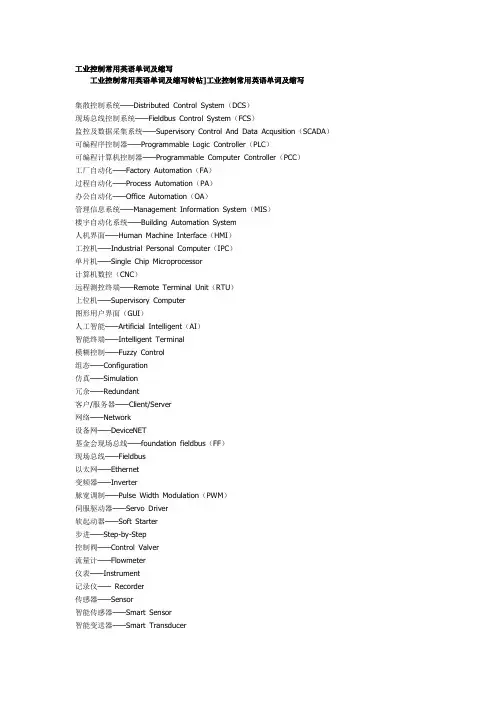
工业控制常用英语单词及缩写工业控制常用英语单词及缩写转帖]工业控制常用英语单词及缩写集散控制系统——Distributed Control System(DCS)现场总线控制系统——Fieldbus Control System(FCS)监控及数据采集系统——Supervisory Control And Data Acqusition(SCADA)可编程序控制器——Programmable Logic Controller(PLC)可编程计算机控制器——Programmable Computer Controller(PCC)工厂自动化——Factory Automation(FA)过程自动化——Process Automation(PA)办公自动化——Office Automation(OA)管理信息系统——Management Information System(MIS)楼宇自动化系统——Building Automation System人机界面——Human Machine Interface(HMI)工控机——Industrial Personal Computer(IPC)单片机——Single Chip Microprocessor计算机数控(CNC)远程测控终端——Remote Terminal Unit(RTU)上位机——Supervisory Computer图形用户界面(GUI)人工智能——Artificial Intelligent(AI)智能终端——Intelligent Terminal模糊控制——Fuzzy Control组态——Configuration仿真——Simulation冗余——Redundant客户/服务器——Client/Server网络——Network设备网——DeviceNET基金会现场总线——foundation fieldbus(FF)现场总线——Fieldbus以太网——Ethernet变频器——Inverter脉宽调制——Pulse Width Modulation(PWM)伺服驱动器——Servo Driver软起动器——Soft Starter步进——Step-by-Step控制阀——Control Valver流量计——Flowmeter仪表——Instrument记录仪——Recorder传感器——Sensor智能传感器——Smart Sensor智能变送器——Smart Transducer虚拟仪器——Virtual Instrument主站/从站——Master Station/Slave station操作员站/工程师站/管理员站——Operator Station/Engineer Station/Manager Station。
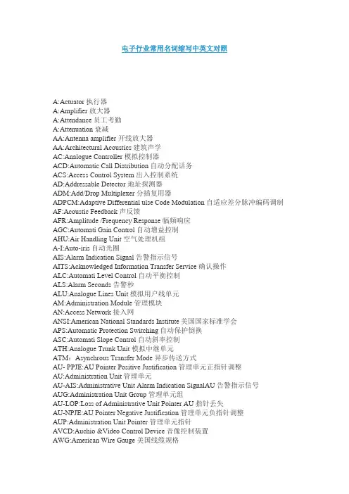
电子行业常用名词缩写中英文对照A:Actuator 执行器A:Amplifier 放大器A:Attendance员工考勤A:Attenuation衰减AA:Antenna amplifier 开线放大器AA:Architectural Acoustics建筑声学AC:Analogue Controller 模拟控制器ACD:Automatic Call Distribution 自动分配话务ACS:Access Control System出入控制系统AD:Addressable Detector地址探测器ADM:Add/Drop Multiplexer分插复用器ADPCM:Adaptive Differential ulse Code Modulation 自适应差分脉冲编码调制AF:Acoustic Feedback 声反馈AFR:Amplitude /Frequency Response 幅频响应AGC:Automati Gain Control自动增益控制AHU:Air Handling Unit 空气处理机组A-I:Auto-iris自动光圈AIS:Alarm Indication Signal 告警指示信号AITS:Acknowledged Information Transfer Service确认操作ALC:Automati Level Control 自动平衡控制ALS:Alarm Seconds 告警秒ALU:Analogue Lines Unit 模拟用户线单元AM:Administration Module管理模块AN:Access Network 接入网ANSI:American National Standards Institute美国国家标准学会APS:Automatic Protection Switching 自动保护倒换ASC:Automati Slope Control 自动斜率控制ATH:Analogue Trunk Unit 模拟中继单元ATM:Asynchrous Transfer Mode 异步传送方式AU- PPJE:AU Pointer Positive Justification 管理单元正指针调整AU:Administration Unit 管理单元AU-AIS:Administrative Unit Alarm Indication SignalAU告警指示信号AUG:Administration Unit Group 管理单元组AU-LOP:Loss of Administrative Unit Pointer AU指针丢失AU-NPJE:AU Pointer Negative Justification管理单元负指针调整AUP:Administration Unit Pointer管理单元指针AVCD:Auchio &Video Control Device 音像控制装置AWG:American Wire Gauge美国线缆规格BA:Bridge Amplifier桥接放大器BAC:Building Automation & Control net建筑物自动化和控制网络BAM:Background Administration Module后管理模块BBER:Background Block Error Ratio背景块误码比BCC:B-channel Connect ControlB通路连接控制BD:Building DistributorBEF:Buiding Entrance Facilities 建筑物入口设施BFOC:Bayonet Fibre Optic Connector大口式光纤连接器BGN:Background Noise背景噪声BGS: Background Sound 背景音响BIP-N:Bit Interleaved Parity N code 比特间插奇偶校验N位码B-ISDN:Brand band ISDN 宽带综合业务数字网B-ISDN:Broad band -Integrated Services Digital Network 宽带综合业务数字网BMC:Burst Mode Controller 突发模式控制器BMS:Building Management System 智能建筑管理系统BRI:Basic Rate ISDN 基本速率的综合业务数字网BS:Base Station基站BSC:Base Station Controller基站控制器BUL:Back up lighting备用照明C/S: Client/Server客户机/服务器C:Combines 混合器C:Container 容器CA:Call Accounting电话自动计费系统CATV:Cable Television 有线电视CC:Call Control 呼叫控制CC:Coax cable 同轴电缆CCD:Charge coupled devices 电荷耦合器件CCF:Cluster Contril Function 簇控制功能CD:Campus Distributor 建筑群配线架CD:Combination detector 感温,感烟复合探测器CDCA:Continuous Dynamic Channel Assign 连续的动态信道分配CDDI:Copper Distributed Data 合同缆分布式数据接口CDES:Carbon dioxide extinguisbing system 二氧化碳系统CDMA:Code Division Multiplex Access 码分多址CF:Core Function 核心功能CFM:Compounded Frequency Modulation 压扩调频繁CIS:Call Information System 呼叫信息系统CISPR:Internation Special Conmittee On Radio Interference 国际无线电干扰专门委员会CLNP:Connectionless Network Protocol 无连接模式网络层协议CLP:Cell Loss Priority信元丢失优先权CM:Communication Module 通信模块CM:Configuration Management 配置管理CM:Cross-connect Matrix交叉连接矩阵CMI:Coded Mark Inversion传号反转码CMISE:Common Management Information Service公用管理信息协议服务单元CPE:Convergence protocol entity 会聚协议实体CR/E:card reader /Encoder (Ticket reader )卡读写器/编码器CRC:Cyclic Redundancy Check 循环冗佘校验CRT:Cathode Ray Tabe 显示器,监视器,阴极射线管CS: Convergence service 会聚服务CS:Cableron Spectrum 旧纳档块化技术CS:Ceiling Screen 挡烟垂壁CS:Convergence Sublayer合聚子层CSC:Combined Speaker Cabinet 组合音响CSCW:Computer supported collaborative work 计算机支持的协同工作CSES:Continuius Severely Errored Second 连续严重误码秒CSF:Cell Site Function 单基站功能控制CTB:Composite Triple Beat 复合三价差拍CTD:Cable Thermal Detector 缆式线型感温探测器CTNR:carrier to noise ratio 载波比CW:Control Word 控制字D:Directional 指向性D:Distortion 失真度D:Distributive 分布式DA:Distribution Amplifier 分配的大器DBA:Database Administrator数据库管理者DBCSN:Database Control System Nucleus数据库控制系统核心DBOS:Database Organizing System 数据库组织系统DBSS:Database Security System 数据库安全系统DC:Door Contacts大门传感器DCC:Digital Communication Channel数字通信通路DCN:Data Communication Network 数据通信网DCP-I:Distributed Control Panel -Intelligent智能型分散控制器DCS:Distributed Control System集散型控制系统DDN:Digital Data Network 数字数据网DDS:Direct Dignital Controller直接数字控制器DDW:Data Describing Word 数据描述字DECT:Digital Enhanced Cordless Telecommunication增强数字无绳通讯DFB:Distributed Feedback 分布反馈DID:Direct Inward Dialing 直接中继方式,呼入直拨到分机用户DLC:Data Link Control Layer 数据链路层DLI:DECT Line InterfaceDODI:Direct Outward Dialing One 一次拨号音DPH:DECT PhoneDRC:Directional Response Cahracteristics 指向性响应DS:Direct Sound 直正声DSP:Digital signal Processing 数字信号处理DSS:Deiision Support System 决策支持系统DTMF:Dual Tone Multi-Frequency 双音多频DTS:Dual -Technology Sensor 双鉴传感器DWDM:Dense Wave-length Division Multiplexing 密集波分复用DXC:Digital Cross-Connect 数字交叉连接GAP:Gaussian (filtered)Frequency Shift Keying 高斯滤波频移键控GBS:Glass Break Sensors 玻璃破碎传感器GC:Generic Cabling 综合布线GIB:Generic Information Block 通用信息模块GNE:Gateway Network Element网关GSM:Global System for Mobile communications全球移动通信系统H:Hybrid 混合式HCBS:High C Bus Servers Unit 高速C总线服务单元HCS:Higher order Connection Supervision高阶连接监视HD:Heat Detecter 感温探测器HDB3:High Density Bipolar of order 3code 高密度双极性码HDLC:High Data Link Control 高级数据链路控制HDLC:High Digital Link Control 高级数据链路控制HDSL:High-bit -rate Digital Subscriber Link 高比特数字用户链路HDTV:High Definition Television 高清淅度电视HEC:Header Ervor Control:信头差错控制域HEMS:High -level Entity Management system高级实体管理系统HFC:Hybrid fiber coax 光纤-同轴电缆混合系统HGRP:Home Optical Network 华为公司专用协议HIFI:High Fidelity 高保真度HIPPI:High Performance Parrallel Interface高性能并行接口HMP:Host monitoring protocol 宿主机监视协议HOA:High Order Assembler高阶组装器HOAPID:High Order Path Access Point Identifier高阶通道接入不敷出点标识符HOI:High Order Interface高阶接口HONET:Home Optical Network 华为综合业务接入网商标HO-TCM:High Order Tandem Connection Monitor高阶通道串联连接监控HOVC:High Order Virtual Container 虚容器HPA:High order path Adaptation高阶适配HPC:High order path Connection高阶通道连接HPOM:High -order Path Overhead Monitor高阶通道开销监视器HPP:High -order path Protection高阶通道保护HP-RDI:Higher order path -Remote Defect Indication高阶通道接收缺陷指示HP-REI:Higher order Path-Remote ErrorIndication高阶通道远端错误指示HPT:High order path Termination高阶通道终端HRDS:Hypothetical Reference Digital Section假设参考数字段HSUT:High -order path Supervision Unequipped Termination高阶通道监控未装装载终HVAC:Heating Ventilation Air Conditioning暖通空调HWS:Hot Water Supply热水供应系统I:Interference 串扰IA:Intruder Alarm防盗报警ICMP:Internet Control Message Protocol控制信息协议IDC:Insucation Displacement Connection绝缘层信移连接件IDS:Industrial Distribution System 工业布线系统IFC:Intelligent Fire Controller 照明智能控制器ILD:Inject Light Diode 注入式激光二极管IM:Impedance Matching 阻抗匹配IMA:Interactive Multimedia Association交互式多媒体协议IM-DM:Intensity Modulation-Direction Modulation直接强度调制IN:Information Network 信息网IO:Information Outlet信息插座IOS:Intelligent Out Station 智能外围站IPEI:International Portable国际移动设备标识号IPTU:Indoor Pan &Tilt Unit 室内水平俯仰云台IPUI:International Portable User Identity国际移动用户标识号ISD:Ionization Smoke Detector 离子感烟探测器IT:Information Technology 信息技术ITU:International Telecommunications Union 国际电信联盟ITU-T:原名CCITT,是国际电信联盟的一个委员会ITV:Interactive Tevevision 交互式电视JIT-Discussion conference system 即席发言系统L:Lens摄像机镜头LAN:Local Area Network 局域网LAPB:Link Access Procedure-Balanced 链路接入规程----平衡LAPD:Link Access Procedure D-channel D信道链路访问协议LCD:Liquid Crystal Display 液晶显示屏LCL:Longituchinal Conrorsion Loss纵模变换损耗LCN:Local Communication Network 本地通信网LCS:Lower order Connection Supervision低阶连接监视LD:Laser Diode激发二极管LE:Local Exchange本地交换网LED:Light Emittirng Diode发光二极管LIU:Lightguide Interconnection Unit光纤互连装置LLC:Logic Link Control Layer逻辑链路控制层LLME:Low Layer Management Entity低层管理实体LM:Lerel Modulation电平调节LNA:Low Noise Amplifier低噪音放大器LOF:Loss Of Frame 帧丢失LOI:Low Order Interface低阶接口LOP:Loss Of Pointer 指针丢失LOS:Loss Of Signal 信号丢失LO-TCM:Low Order Tandem Connection Monitor低阶通道串联连接监视器LOVC:Low Order Virtual Container 低阶虚容器LPA:Lower order qath Adaptation低阶通道适配LPC:Lower order Path Connection低阶通道连接LPOM:Low-order Path Overhead Monitor低阶通道开销监视器LPP:Low-order Path Protection 低阶通道保护LPT:Lower order Path Termination低阶通道终端LSBCM:Laser Base Current Monitor激光器偏流监视LSUT:Low -order path Supervision Unequipped 低阶通道监控未装载终端LTC:Londline Trunk Coutroller有线线路分配器LU:Line Unit 线路单元Medium Access Control Layer 介质访问控制层MBMC:Multiple Burst Mode Controller 多突发模式控制器MCF:Message Communication Function消息通信功能MD:Mediation Device中介设备MFPB:Multi-Frequency Press Button多频按键MIB:Management Information Base 管理信息库MIC:Mediu Interface Connector 介质接口连接器MIO:Multiuser Information Outlet 多用户信息插座MLM:Multi-Longitudinal Mode 多纵模MM:Mobile Management 移动管理MMDS:Maltichanned Microware Distribution System多路微波分配系统MMO:Multionedia Outlet 多媒体插座MN-NES:MN-Network Element System 网元管理系统MN-RMS:MN-Region Management System 网络管理系统MO:Managed Object 管理目标MSA:Multiplex Section Adaptation复用段适配MS-AIS:Mutiplex Section-Alarm Indication Signal 复用段告警指示信号MSOH:Multiplex Section Overhead 复用段开销MSP:Multiplex Section Protection复用段保护MS-RDI:Multiplex Section-Remote Defect Indication复用段远端缺陷指示MST:Multiplex Section Termination复用段终端MSU:Multi-Subscriber Unit 多用户单元MTIE:Maximum Time Interval Error最大时间间隔误差MUX:Multiplexer 灵活复接器NDF:New DataFlag 新数据标识NDFA:Niobium-Doped Fiber Amplifier 掺铌光纤放大器NE:Network Element 网元NEXT:Near End Crosstalk 近端串扰NMS:Network Management System网络管理系统NNE:Non-SDH Network Element 非SDH网元NNI:Network Node Interface网络节点接口NPI:Null Pointer Indication无效指针指示NWK:Network Layer 网络层NZ-DSF:Non Zero-Dispersion Shift Fiber 非零散位移光纤OAM&P:Operation Administration, Maintenance and Provisioning运行、管理、维护和预置OAM:Operation, Administration and Maintenance操作、管理和维护OBFD:Optical Beam Flame Detector 线型光速火焰探测器OC-N:Optical carrier level-N光载波级NOCR:Optical Character Recogmition光学字符识别OEIC:Optoelectronic Integrated Circuit光电集成电路OFA:Optical Fiber Amplifier 光纤放大器OHP:Overhead Processing开销处理OLT:Optical Line Terminal光纤线路终端ON:Orerall Noise 总噪声ONU:Optical Network Unit 光纤网络单元OOF:Out Of Frame 帧失步OOP:Object Oriental Programming面向对象程序设计OS:Operating System 操作系统OSC:Oscillator 振荡器OSI:Open Systems Interconnection开放系统互连OTDK:Optical Time Doman Reflectometer 光时域反射线OTDM:Optical Time Division Multiplexing 光时分复用PA:Power Amplifier 功率放大器PABX:Private Auntomatic Branch Exchange 程控数字自动交换机PACR:Attonuation to Crosstalk Ratio 衰减与串扰比Paging :无线呼叫系统PAL:Pinhole Alc Lons 针孔型自动亮度控制镜头PARK:Portable Access Rights Key 移动用户接入权限识别码PAS:Public Address System 公共广播音响系统PBX:Private Brancn exchange 程控用户交换机PC:Pan unit&control 云台及云台控制器PC:Proximinty Card 接近卡PCM:Pulse Code Modulation 脉冲编码调制PCS:Personal Communication Service个人通讯服务PDFA:Praseodymium-Doped Fiber Amplifier 掺镨光纤放大器PDH:Plesiochronous digital Hierarchy 准同步数字系列PDN:Public data network 公用数据网PDS:Premises Distribution Systemn建筑物结构化综合布线系统PF:Pressurization Fan 加压风机PG:Pressure Gradient 压差式PID:Passire Infrared Detector 被动式红外传感器PJE:Pointer Justification Event 指针调整事件PLC:Programmerable Logic Controller 可编程控制器PM:Power Matching 功率匹配PMS:Prooerty Management system 资源管理系统PO:Pressure Operated 压强式POH:Path Overhead 通道开销PPI:PDH Physical InterfacePDH物理接口Preamplification :前置放大PRI:Primany Rate Interface 基群速率接口PRM:Patter Recogniton Method模式识别法PSC:Protection Switching Count 保护倒换计数PSD:Photoelectric Smoke Detector 光电感烟探测器PSD:Protection Switching Duration保护倒换持续时间PSK:Phase Shift Keying 移相键控PSNT:Ponver Sum Next 综合近端串扰PSPDN:Packet switched Public Data Network 公众分组交换网PSTN:Public Switch Telephone Network 公用交换电话网PU:Pick Up 拾音器PVC:Polyvingl chloride 聚氯乙烯PVCS:Public video conferring system 公用型会议电视系统PWS:Power system 电源系统ITU-T:International Telecommunication Union-Telecommunication Sector国际电信联盟-电信标准部R:Receiver 终端解码器R:Reverberator 混响器RC:Radio Communication移动通信RC:Room’s Coefficient 房间系数RCU:Remote Control Units 终端控制器RDI:Remote Defect Indication 远端失效指示REG:Regenerator 再生器Resolution:清晰度RF:Radio Frequency 射频RHE:Romote Head End 远地前端RMC:Repeater Management Controller天线信道控制器RMS:Root Mean Square 均方根值RMU:Redundancy Memory Unit 冗佘存贮器RORTD:Rate Of Rise Thermal Detector 差温探测器RR:Reverberation Radius 混响半径RS:Reflected sound 反射场RSOH:Regenerator Section Ouerhead 再生段开销RSSI:Radio Signal Strength IndicatorRST:Regenerator Section Termination 再生段终端RSU:Remote Subscriber Unit 远端用户单元RT:Real Time 实时RT:Reverberation Time 混响时间RWS:Remote Workstation 远端工作站S:Sprinkler 分配器S:Stereo 双声道S:Strike 电子门锁SAA:Sound Absorption Ability 吸声能力SAR:Segmetation and reassembly sublayer 拆装子层SATV:Sate Llite 卫星电视SBS:Synchronous Backbone System 同步信息骨干系统SBSMN:SBS SBS Management Network 系列传输设备网管系统SC:Smart Card 智能卡SC:Subscriber Connector (Optial Fiber Connector)用户连接器(光纤连接器)SC:Supervisong Center 中央站监控中心管理中心SCADA:监控和数据采集软件SCB:System Control Board 系统控制板SCC:System Control&Communication系统通信控制SC-D:Saplex sc commector 双ISC连接器SCD:Sound Console Desk 调度台SCPC:Single Chnanel Per Carrier 卫星回程线路SCS:Stractured Cabling System 结构化布线系统SD:Signal Degraded 信号劣化SD:Smoke damper 排烟阀SD:Smoke Detector 感烟探测器SD:System Distortion 系统失真SDCA:Synchronization DCA同步数据通讯适配器SDMA:Spaee Division Multiplex Access容分SDXC:Synchronous Digital Cross Connect 同少数字交叉连接SE:Sound Energy 声能SEC:SDH Equipment Clock SDH 设备时钟SED:Sound Energy Density 声能密度SEEF:Smoke Extractor Exhaust Fan 排烟风机SEMF:Synchronous Equipment Management Function同步设备管理功能SES:Severely Errored Second 严重误码秒SESR:Severely Errlred Second Ratio严重误码秒比率SETPI:Synchronous Equipment Timing Physical Interface同步设备定时物理接口SETS:Synchronous Equipment Timing Source同步设备定时源SF:Spur Feeder 分支线SF:Subscribers Feeder 用户线SFN:Sound Field Nonunifornity 声场不均匀度SFP:Sound Field Processor 声场处进器SI:Sound Installation 音响设备SI:Sound Insulation隔音SICS:Simultaneous Interpretation Conference system同声传译系统SIPP:Service Interface and protocol processing unit业务接口和协议处理单元SLC:Sate llite Commumication 卫星通信SLI:Synchronous Line Optical Interface同步线路光口板SLIC:Subscriber Line Interface Controller用户线接口控制器SLM:Signal Label Mismatch 信号标记失配SM:Synchronous Multiplexer同步复用器SMF:System management function系统管理功能SMS:SDH Management Sub -Network SDH管理子网SNA:System Network Architecture 系统网络建筑SNI:Service Node Interface业务节点接口SNK:Sighal To Noise Ratio 信噪比SOA:Semiconductor Optical Amplifier半导体光放大器SOH:Section Overhead 段开销SONET:Synchronous Optical Network同步光网络SPF:Service Port Function业务口功能SPI:SDH Physical InterfaceSDH物理接口SPL:Sound Pressure Level 声压级SRL:Stractural Return Loss 结构器波损耗SS:Shock sensors 震动传感器SS:Sound Source 音源SS:Sprinkler System 自动喷水灭火系统SSB:Single Side Band 单边带调制SSM:Synchronous Status Message 同步状态信息SSU:Scan and Signal Unit 扫描及信号单元ST:Straight Tip 直通式光纤连接器ST:Subscribers Tap 用户分支器STB:Set -Top -Box 机项盒STC:Short -Term Card 计时票STE:Signaling Transfer Equipment 信令转换设备STG:Synchronous Timing Generator同步定时发生器STI:Surface fransfer Inpedane 表面传输阻扰STI:Surface Tranfer Inpedance 表面传输阻抗STM-N:Synchronous Transport Module level-N同步传送模块等级NSU:Subscriber Unit用户单元SV:Smoke Vent 排烟器SVCS:Sound Veinforcement System扩声系统T:Teletext 可视图文T:Terminal 终端机TA:Trunk Amplifier 干线放大器TC:Telecommunication Closet 通信插座TC:Transient Characteristic瞬间特性TCI:Trunk cabling interface 星形连接TCP/P:Transmission Control Protocol Inter-network Protocol传输控制协议/网间协议TCS:Tele Communication System 通信系统TCS:Telecommunication System 通讯系统TD:Ticket Dispemser 发卡机TDD:Time Division Dual 时分双工TDEV:Time Deviation时间偏差TDM:Time Division Multiplexing时分复用TDMA:Time Division Multiple Address时分多址TDS:Time division switching 时分交换结构TELEX:用户电报电传TEP:时间/事件软件TF:Transfer Function传送功能TFCC:Transmission frequenay Characteristic传输频率特性TGNP:The Greatest Noise Power 最大噪声功率TIM:Trace Identifier Mismatch追踪识别符失配TM:Termination Multiplexer 终端复用器TMN:Telecommunication Management Network 电信管理网TMN:Telecommunication Management Network电信管理网TNL:Total Noise Level 总噪声级TO:Telecommunications Outlet通信插座TP:Tunst Pair 对绞线TR:Token Ring 令牌网TSI:Timeslot Interxhange时隙交换TSU:Time Switching Unit 时隙交换单元TTF:Transport Terminal function 传送终端功能TTS:Tri Technology Sensor三鉴传感器TU:Tributary Unit 支路单元TUG:Tributary Unit Group 支路单元组TU-LOM:TU-Loss Of Multi-frame 支路单元复帧丢失TUP:Tributary Unit Pointer 支路单元指针TUPP:Tributary Unit Payload Process支路净荷处理UAT:Ultra Aperture Terminal 超小口径卫星地面接收站UL:Underwriters Laboratory 担保实验室UM:Unidirectional Microphines 单指向性传声器VA:Vacant auditoria 空场VCI:Virtual chammel identifier 虚信道标识VCS:vIdeo conferphone system 会议电视系统VI:Video interphone 可视对讲门铃Video switchers 图象切换控制器Videotext :可视图文VOD:Video on demand 视频点播VSAT:Very Small Aperture Terminal 甚小口径天线地球站。
电厂热控专业常用英文缩写Revised as of 23 November 2020A /D a n a l o g t o d i g i t a l 模拟/数字['n l :g ] A C K a c k n o w l e d g e 确认['d i d i t l ] AIanalog input 模拟量输入 AMManalog masterm o d u l e 模拟主模件A M P L a m p l i f i e r 放大器['m p l i f a i ] A N A L a n a l y s i s 分析['n l s i s ]A N A L Z a n a l y z e r 分析仪表 ['n ,l a i z ] A N L G ?a n a l o g 模拟['n n i e i t ] 通告者 ANNannunciatorsystem 报警系统 ANNannunciator 信号装置,报警器 AOanalogoutput 模拟量输出 AOanalog output 模拟输出 AOLanalog output to loop (圈,环)对FC30环的模拟输出 A V G a v e r a g e 平均的 APOauxiliary[:g'ziljri](辅助的)plantoperator 辅助设备操作员 B K b r a k e 制动器A T T E N a t t e n u a t o r ['t e n j u e i t ]衰减器,消声器 A V A I L a v a i l a b l e 可用的 BHPbrakehorsepower 制动马力 BLKblock 程序块,封闭 B L N K b l a n k 空白,熄灭 C -C c e n t u r e -t o -c e n t u r e 中心距,中心之间 C F G N c o n f i g u r a t i o n 轮廓,构架,组态 C H c h a i n 链,环[k n ,f i g j u 'r e i n ] 结构 C H A N c h a n n e l 通道 C H G c h a n g e 改变 CIUcomputerinterfaceunit 计算机接口单元 ['intfeis]界面,分界面 接合部 C L c e n t u r e l i n e 总线,中心线CMS co mpu t ermo ni to rin gsyst e m 计算机监视系统C ND N R c o n d i t i o n e r [k n 'd i n ]调节器C N G R c o n g r u e n c e相同,重合 C N T c o n t a c t ['k n t k t ]接触,触点 C N T L c o n t r o l 控制 C N T L R c o n t r o l l e r 控制器 C N V R c o n v e y o r [k n 'v e i ]传送装置 C O N c o n n e c t o r 连接器 C O N S T c o n s t a n t ['k n s t n t ]恒定的,常数 C O N T c o n t i n u o u s 连续的 C O N V c o n v e r t e r [k n 'v :t ]转换器 C O O R D c o o r d i n a t o r /c o o r d i n a t e 调度员/协调 [ku':dineit] 协调者 CRcontrolrelay 控制继电器 CRTcathode['kθud](阴极)raytube 显示器 CScontrolswitch 控制开关 CTRcentre 中央 CTRLZDcentralized ['sntrlaiz] 集中 CVcontrolvalve 控制调门,调节器 D/Adigitalto analogconverter 数字/模拟转换器 DASdataacquisitionsystem 数据采集系统 DASdataacquisitionsystem 数据采集系统 DCSdistributedcontrolsystem 分散控制系统 DCSdistributedcontrolsystem 分散控制系统 DDdevicedriver(fc123)设备驱动器 DETdetector 检测器 DETDdetected 检测到的 DETNdetection 检测 DEVNdeviation 偏差 DIdigitalinput 数字输入 DIAGLdiagonal 对角的 DIAPHdiaphragm 流量孔板,薄膜DIFFdifferential 有差的DIFFTdifferentialtemperature温差DIGdigital数字DISTRBdisturbance扰动,干扰DLYdelay延迟,滞后DOdigitaloutput数字输出DOLdigitaloutput to loop(fn45)到FN45环的数字输出DPdifferentialpressure压差DSBLDdisabled不能的DSVdoublesolenoidvalve双螺线管阀门,电磁阀['sulinid] 螺线管EWSengineerworkstation工程师工作站F/Cfallclose出故障时自动关闭F/Ofallopen出故障时自动打开FBfeedback反馈['fknl] 机能的FDG?functionaldrivegroup功能驱动组FDGOFFfunctional drive group off功能驱动组关FDGONfunctionaldrivegroupon功能驱动组开FGCTLfunctionalgroupcontrol功能组控制 [,indi'kei?n] 指示;指点;表示FISflowindicationswitch流量指示器FLTfault故障,缺陷FSflowswitch流量开关GAgage/gauge仪表[geid][geid]规,表,计GOVgovernor ['gvn]调节器HIhigh高HIHIhighhigh高高['int?feis] 界面HIShumansysteminterface操作员系统接口I/O?input/output输入/输出['k:rnt] 现时的电流, 水流, 气流I/P?currenttopneumatic converter电动/气动转换器[nju:'mtik] 空气的,气体的INFOinformation信息,资料INSTRinstrument ['instrum?nt]仪表INTLK?interlock [,int'lk]联锁IPB?intraplantbus厂内总线KBDkeyboard键盘L/Olockout闭锁LABlaboratory [l'brtri]试验室LCD 液晶显示柱LCKDlocked闭锁的,锁气的LDA 甩负荷预测LIMlimit/limiter限制/限制器LIMSWlimitswitch限位开关LMPlamp灯LMTGlimiting 限制,极限的LOlow低LOGlogic逻辑LOLOlowlow低低LPLlighting panel照明盘LVDTlinearvoltagedifferentialtransformer线性差动变送器['vultid] [,dif'renl] [trns'f:m]LVLlevel水平,电平LWRlower ['lu]更低LWRGlowering['luri]降低M/A?manual/automatic手动/自动MAmaster控制[,:t'mtik]MALFmalfunction故障,失灵[ml'fkn]n. 故障 MANmanual手动的MAXmaximum最大['mksimm] 最大限度MCPNLmaincontrolpanel主控盘['pnl]n.嵌板; 仪表板MCRmaincontrolroom主控室MCSmodulationcontrolsystem模拟量控制系统[,mdju'lein] n. 调音,调节MCSmanagementcommandsystem管理命令系统['mnidmnt] 管理[k'mɑ:nd] vi. 命令;控制MDLmaximumdifferentiallimit最大偏差限制[dif'renl] n. 微分;差别MFCmanyfunctioncontroller多功能控制器['fkn]职责;函数[kn'trul] 控制器,管理者MFP?multifunctionprocessor多功能处理器MIDmiddle中间的MINminimum最小['minimm] 最小化;最小值MINminute分钟MINIminiature小型的,微型的['mini?t]MNmain主MODLmodule[du:l] n. 模数;组件模块MONmonitor监视器MPRCSmicroprocessor[maikru'pruses]微处理器['m?ltipleks] a. 多样的,多重发讯MPX?multiplex/multiplexer?多路传输['mlti,pleks] 多路器MTBF平均无故障工作时间MULT multiple['mltipl] 多重的;许多的,并联的N AUTOnotinauto不在自动N AVALnotavailable不可用的N OFF notoff没关N ONnoton没开N OPRnotinoperate不在运行中N PERMnotpermitted([p'mit] 许可;允许)不允许的N READnotready没准备好N RUNnotrunning 没有运行N SATnotsatisfled不满足条件satisfaction [stis'fkn] 满意,满足N TESTnotintest不在试验中N/Anotapplicable不适用的['plik-]可应用的NACTnotactive无效的NORnot or或非NPERMnopermissives不允许[p'misiv] 许可的;宽容的OIUoperatorinterfaceunit操作员接口单元 [nju(:)'m?tik] 气动的,气胎P/Epneumatic to electrical converter气动/电动转换器[kn'v:t(r)] 转换器PCUprocesscontrolunit过程控制单元PCUprocesscontrolunit过程控制单元PCVprocesscontrolview过程控制图[vju:]视野,风景v. 看,考虑PIpulseinput脉冲量输入[p?ls] 脉搏PLCprogrammablelogic controller可编程控制器['prgrmbl] 可编程的PLCprogrammablelogic controller可编程逻辑控制器['pail?t] 行员,领航员,引航员PLTpilot副的,控制的,指示PLTNplater ['pleit]台板,屏式POpulseoutput脉冲量输出PPS 电厂保护系统PRCSprocess过程PROBprobe [pr?ub]探头,传感器PROGprogram程序PROLNGprolong [pr'l, 'l:]持续时间长PROTprotection保护PTpoint值,点PTRIPprotectiontrip保护跳闸PUpickup传感器n. 旅行,摔倒,差错RESETreset复位RSTreset复位RSTRDrestricted [ris'triktid]限制的,禁止的RSVRreservoir水库,储存器,滞止S/Gsubgroup子群组[s?b] 地铁,潜艇,替补队员SCSsequencecontrolsystem顺序控制系统SEQsequence顺序['si:kw?ns]SERsequenceeventrecorder事故顺序记录SERsequenceofeventsrecorder事故的顺序记录[ri'k:d]录音机SIswitchinput开关量输入SIGsignal信号SILsilence无声的SILENCEsilence消音SMPLsample ['s?mpl]取样,样品,标本SOswitchoutput开关量输出SOEsequence ofevent事故顺序SOEsequenceofevents事故顺序SOLsolenoid['sulinid]螺线管SOVsolenoidoperatedvalve螺线管控制门,电磁阀STORstorage储存器,蓄电SUBRsubroutine [,s?bru:'ti:n]子程序SUCCsuccessful成功的SUMRsummer夏天,加法器T/Cthermocouple ['θ:mu,kpl]热电偶TCtripcoil跳闸线圈TCOtripcutout跳闸断开TESTtest试验TLtestlink试验连接TRBLtrouble故障TRGRtrigger ['trig]触发器TRIPDtripped跳闸的TSthermoswitch热电偶开关,. 热开关;热敏开关;温度调节器;热电偶继电器TSTtest试验UNSATSFunsatisfactory不满足条件的UNSUCCunsuccessful失败的XDCRtransducer变送器trnz'dju:s] 转换器,传感器汽轮机常用英文缩写A/M auto/manual 自动/手动ADS automatic dispatch system 自动调度系统[dis'p?t] 派遣,分派AGC automatic generator control 机组自动发电控制['denreit] 发电机,发生器AOP auxiliary oil pump 辅助油泵auxiliary [:ɡ'ziljri] 辅助的;副的;附加的AOV air operated valve 汽动门AST automatic stop trip 自动停机跳闸系统A-STP auto stop 自动停止A-STRT auto start 自动启动ATC automatic turbine control 汽轮机自动控制['t:bin, -bain] n. 涡轮A-TRIP auto trip 自动跳闸AUX auxiliary 辅助的BAF baffle ['b?fl]隔板,挡板BASE base 基本方式BBL barrel ['brl]圆筒型支架BF boiler follow 锅炉跟随方式['bil]BKUP backup ['bkp]备用BOPMS balance of plant master system 机组辅助设备主控顺序[plɑ:nt] 工厂BP base plate 底版,支撑板BPS bypass control system 旁路控制系统BRG bearing ['bεri]轴承BW backwash 反洗BYP bypass 旁路CAB cabinet ['k?binit]小室CAEP condenser air extraction pump 真空泵[kn'dens] 凝结器,冷却器[iks'trkn] 抽出CAV cavity ['k?viti] 洞,空穴,腔CAVIT cavitation [,kvi'tein]汽蚀CC closing coil 闭式循环CCCW closed circuit cooling water 闭式循环冷却水['s:kit] 电路,回路['ku:li]CCCWP closed circuit cooling water pump 闭式循环冷却水泵CCW condenser circulating water 循环水['s:kjuleiti] 循环,流通CCW counter clockwise 逆时针的['kaunt]相反的['kl?kwaiz] a. 顺时针方向的CCWPcondenser circulating water pump循环水泵CE case expansion 缸胀[keis] 情形,情况,箱[iks'pnn] 扩大,膨胀CEP condensate extraction pump 凝结水泵CHEM chemical 化学CIV close interceptor valve 关中压调门[,int'sept] 拦截机;妨碍者CLD cold/cooled 冷的CLF clarifier ['klrifai] 净化器CLG cooling 冷却CLNG cleaning清洁,净化CLR cool 冷却器CLS close 关 CLSD closed 已关CLU clutch [klt]离合器,控制;手CND conduit ['k?ndit]管道,导线管CNDCTconductivity [kndk'tiviti]导电率,传导率COAG coagulant [ku'ɡjulnt]凝结剂COAX coaxial ['ku'ksl]同轴的COND condenser [kn'dens]凝汽器COOL coolant ['ku:l?nt]冷却介质COR coordination [ku,:di'nein]协调控制方式COV cover ['kv]外壳CPLG coupling ['kpli]偶合器,连轴器CRH cold reheat 冷再热CRIT critical ['kritik?l]临界的,关键的CSG casing ['keisi]汽缸CT combustion turbine 燃气轮机[km'bstn] 燃烧CTW cooling tower 冷水塔CV control valve 高调门CW circulating water 循环水['s:kjuleiti]CW cooling water 冷却水CWP circulating water pump 循环水泵CYL cylinder ['silind]汽缸D density ['densiti]密度,浓度DE differential expansion 胀差DEA deaerator [di:'εreit]除氧器DECR decrease 下降DEG degree(s) 度,学位DEGC degrees celsius 摄氏度['selsj?s] 摄氏的DEH digital electro-hydraulic control system 数字电液调节系统。
plc英语词汇对照表PLC相关词汇发音词性释义。
PLC[ˌpiː el ˈsiː]n.(名词)可编程逻辑控制器(Programmable Logic Controller)Input[ˈɪnpʊt]n.(名词)/v.(动词)输入;投入;把…输入计算机。
Output[ˈaʊtpʊt]n.(名词)/v.(动词)输出;产量;输出端;输出量;输出数据;(将数据)输出。
Relay[ˈriːleɪ]n.(名词)/v.(动词)继电器;接替人员,轮换者;传递;转播;转接(电话);转播(电视或广播讯号)Sensor[ˈsensə(r)]n.(名词)传感器;敏感元件;探测设备。
Actuator[ˈæktʃueɪtə(r)]n.(名词)执行器;促动器;作动器;激励器。
Logic[ˈlɒdʒɪk]n.(名词)逻辑;逻辑学;逻辑性;推理方法;逻辑系统。
Programming[ˈprəʊɡræmɪŋ]n.(名词)编程;程序设计;(节目)编排,选编。
Instruction[ɪnˈstrʌkʃn]n.(名词)指令;指示;教导;用法说明;操作指南。
Address[əˈdres]n.(名词)/v.(动词)地址;演说;称呼;处理(问题);向…说话;称呼(某人);写明收件人姓名地址。
Data[ˈdeɪtə]n.(名词)数据;资料;材料(datum的复数)Bit[bɪt]n.(名词)位;比特(二进制信息单位)Byte[baɪt]n.(名词)字节;位组;8个比特。
Register[ˈredʒɪstə(r)]n.(名词)/v.(动词)寄存器;登记;注册;记录;挂号邮寄;正式提出(投诉等)Latch[lætʃ]n.(名词)/v.(动词)门闩;插销;碰锁;弹簧锁;锁住;闩上;抓住;占有。
Counter[ˈkaʊntə(r)]n.(名词)/v.(动词)计数器;柜台;(对意见、态度等的)反对;反驳;抵制;(拳击或摔跤比赛中的)击打,反击;计算;计数;(尤指按顺序)数数。
自动化常用英文缩写AMS Alarm Management System报警管理系统APC Advanced Process Control高级过程控制BEM Battery Extension Module电源扩展模块BOG Boil Off Gas气体蒸发C&E Cause and Effect起因和影响CAS Cascade级联CAT5 Category 5 type cable 5类线CCB Central Control Building中心控制大楼CCR Central Control Room中心控制室CCTV Closed Circuit Television闭路电视CP Control Panel控制面板CPM DCS Controller (C200)DCS 控制器(C200)CPU Central Processing Unit中央处理器CSMA/CD Carrier Sense Multiple Access with Collision Detection载波监听多路访问/冲突检测CV Control Valve控制阀DCS Distributed Control System集散控制系统DIN Deutsche Industries Norm (German Industrial Standard)Deutsche工业标准(德国工业标准)DP Differential Pressure微分压力EEMUA Engineering Equipment and Material Users Association工程设备和材料用户协会EMC Electromagnetic Compatibility电磁兼容性ESD Emergency Shutdown紧急停车EWS Engineering WorkStation工程工作站F&G Fire And Gas火气FAT Factory Acceptance Test工厂验收测试FB Functional Block功能模块FGS Fire And Gas System火气系统FIM Field Information Management现场信息管理FIR Field Instrument Room现场设备室FSC Shielded twisted pair故障安全控制器FTA Field Terminal Assembly现场集线端子FTB Field Terminal Block现场模块端子FTE Fault Tolerant Ethernet容错以太网FTEB FTE Bridge Module FTE 网桥模块GPS Global Positioning System全球定位系统GRP Glass Reinforced Plastic玻璃钢HART Highway Addressable Remote Transducer高速可编址远程传感器HEC Honk Kong Electric香港电气HKCG Hong Kong China Gas中国香港燃气HMI Human Machine Interface人机界面HVAC Heating Ventilation And Air Conditioning暖通和空调I/O Input /Output输入/输出IEC International Electro-technical Commission国际电工委员会IOLIM IO Link Interface Module IO 接口模块IOLIM IOs – IO link Interface Module IOs – IO 接口模块IP Ingress Protection入口保护IR Infra-red红外IRP Interposing Relay Panel插入式继电器盘IS Intrinsically Safe本质安全JCR Jetty Control Room码头控制室LAN Local Area Network本地网络LFAP Local Fire Alarm Panel本地火警面版LNG Liquefied Natural Gas液化天然气LTD Level, Temperature, Density combined measurement of LNG tanks LNG罐的液位,温度,密度综合测量MAC Manual Alarm Call point手动报警点MAN Manual手动MC Marshalling Cabinet集线柜MCB Miniature Circuit Breaker小型回路断路器MCC Motor Control Centre电机控制中心MFAP Main Fire Alarm Panel主火警面版MIS Management Information System信息管理系统MMS Maintenance Management System维护管理系统MOS Maintenance Override Switch维护超控开关MOV Motor Operated Valve电机操作阀MTBF Mean Time Between Failures平均故障间隔时间MTO Material T ake Off材料提取MTTR Mean Time To Repair平均修复时间MV Measured Value测量值NG Natural Gas天然气NIS Non Intrinsically Safe非本质安全NPS Nominal Pipe Size标定管道尺寸NTP Net Time Protocol网络时间协议OOS Operational Override Switch可操超控开关OP Output输出OPC Object Linking And Embedding For Process Control基于过程控制的嵌入式对象连接orV Open Rack Vaporizer开架蒸馏器OTS Operator Training Simulator操作员培训模拟器P&ID Process And Instrument Diagram过程和仪表图PCN Plant Control Network工厂控制网络PIN Plant Information Network工厂信息网络PKS Process knowledge system (Honeywell control system) 过程知识系统(Honeywell 控制系统)PLC Programmable Logic Controller可编程逻辑控制器PRT Printer打印机PSU Power Supply Unit电源单元PTFE Polytetrafluoroethane聚四氟乙烯PV Process Value过程阀RM Redundancy Module冗余模块RM Redundancy Module冗余模块RPS Rack Power Supply机架电源RTD Resistance Temperature Detector电阻温度探测器RTIS Real Time Information System实时信息系统RTU Remote Transmission Unit远程传送单元SAT Site Acceptance Test现场验收测试SCADA System of Control And Data Acquisition监视控制与数据采集系统SCV Submerged Combustion Vaporiser水下燃烧蒸馏器SER Sequence Of Event Recorder事件记录序列SIGTTO Society Of International Gas Tanker And Terminal Operators国际液化气船及码头经营人协会SIL Safety Integrity Level安全整合等级SIS Safety Instrumented System安全仪表化系统SP Set Point设置点SS Stainless Steel不锈钢STP Shielded Twisted Pair屏蔽双绞线TC Thermocouple热电偶TCP/IP Transmission Control Protocol/Internet Protocol传输控制协议/网际协议TDAS T ank Data Acquisition System罐数据采集系统TFT Thin Film Technology薄膜技术UCP Unit Control Panel (Packaged Equipment)单元控制面板(打包设备)UPS Uninterruptable Power Supply不间断电源VAC Volts Alternating Current交流电压VCB Vaccum Control Breaker真空控制断路器VDC Volts – Direct Current直流电压VDU Visual Display Unit视频显示装置VESDA Very Early Smoke Detection Apparatus烟尘预报侦测仪VFC Volt Free Contact电压自由触点VSD Variable Speed Drive变速驱动器WAN Wide Area Network广域网AGC Automatic Generation Control 自动发电控制AMR Automatic Message Recording 自动抄表ASS Automatic Synchronized System 自动准同期装置ATS Automatic Transform System 厂用电源快速切换装置AVR Automatic Voltage Regulator 自动电压调节器BCS Burner Control System 燃烧器控制系统BMS Burner Management System 燃烧器管理系统CCS Coordinated Control System 协调控制系统CIS Consumer Information System 用户信息系统CRMS Control Room Management System 控制室管理系统CRT Cathode Ray Tube 阴极射线管DA Distribution Automation 配电自动化DAS Data Acquisition System 数据采集与处理系统DCS Distributed Control System 分散控制系统DDC Direct Digital Control 直接数字控制(系统)DEH Digital Electronic Hydraulic Control 数字电液(调节系统) DMS Distribution Management System 配电管理系统DPU Distributed Processing Unit 分布式处理单元DSM Demand Side Management 需求侧管理EMS Energy Management System 能量管理系统ETS Emergency Trip System 汽轮机紧急跳闸系统EWS Engineering Working Station 工程师工作站FA Feeder Automation 馈线自动化FCS Fieldbus Control System 现场总线控制系统FSS Fuel Safety System 燃料安全系统FSSS Furnace Safeguard Supervisory System 炉膛安全监控系统FTU Feeder Terminal Unit 馈线远方终端GIS Gas Insulated Switchgear 气体绝缘开关设备GPS Global Position System 全球定位系统HCS Hierarchical Control System 分级控制系统LCD Liquid Crystal Display 液晶显示屏LCP Local Control Panel 就地控制柜MCC Motor Control Center (电动机)马达控制中心MCS Modulating Control System 模拟量控制系统MEH Micro Electro Hydraulic Control System 给水泵汽轮机电波控制系统MIS Management Information System 管理信息系统NCS Net Control System 网络监控系统OIS Operator Interface Station 操作员接口站OMS Outage Management System 停电管理系统PAS Power Application Software 电力应用软件PID Proportion Integration Differentiation 比例积分微分PIO Process Input Output 过程输入输出(通道)PLC Programmable Logical Controller 可编程逻辑控制器PSS Power System Stabilizator 电力系统稳定器RTU Remote Terminal Unit 站内远方终端SA Substation Automation 变电站自动化SCADA Supervisory Control And Data Acquisition 数据采集与监控系统SCC Supervisory Computer Control 监督控制系统SCS Sequence Control System 顺序(程序)控制系统SIS Supervisory Information System 监控信息系统TDCS(TDC)Total Direct Digital Control 集散控制系统TSI Turbine Supervisory Instrumentation 汽轮机监测仪表UPS Uninterrupted Power Supply 不间断供电WMS Work Management System 工作管理系统。
LEC 系列电缸简易操作手册LEC 系列控制器为SMC 开发的新型电缸控制器。
适用范围:LES 系列电动滑台 LEY 系列出杆式电缸 LEF 系列无杆式电缸LEH 系列电动夹爪1、产品特点:①内部可存储64步程序②可实现精确定位、力矩输出2、系统构成(以LES 系列电动滑台+LEC系列控制器为例)3、产品结构4、各端口配线及功能详解4-1 CN1端口-DC24V 电源接口端子号 0V M 24V C 24V EMG BK RLS急停信号配线(注意:常闭信号,闭合时正常使用,断开时急停)功能电源- 电机电源+ 控制端口电源+ 急停信号+ 解锁信号+解锁信号配线(注意:闭合时解锁,断开时锁紧,适用于带锁型电缸)4-2 CN2端口-电机电源接口/CN3端口-电机编码器接口/CN4端口-通信线缆接口以上3个端口均为标准插头,直接插入端口即可。
4-3 CN5端口-控制I/O接口 CN5端口用标准线缆示意图:配线图(以NPN 型为例)输入信号:线号A1 A2 A3 A4 A5 A6 A7 A8 A9 A10A11 A12A13线号B1 B2 B3 B4 B5 B6 B7 B8 B9 B10 B11 B12 B13线色茶/黑1 茶/红1名称 COM+COM-说明控制端口DC24V 正控制端口DC24V 负黄/黑黄/红浅绿/黑浅绿/红灰/黑灰/红白/黑1 茶/黑2 茶/红2 黄/黑2 线色SETUP DRIVE RESET SVON 名称原点回归运行报警取消伺服ON说明白/红暂时停止(可继续)步选择信号(2进制)。
输出信号:黄/红浅绿/黑浅绿/红步选择输出信号灰/黑(2进制)灰/红白/黑白/红运行中茶/黑区域内茶/红原点回归完成黄/黑公差内黄/红伺服准备完成浅绿/黑急停中浅绿/红报警注意:上表中粗体红字部分的线为必接线,否则电缸无法正常使用。
其余线缆可根据实际需要选接。
DC24V 正正 DC24V 负负步选择信号2进制组合选定要执行的程序步号,OFF 表示0,ON 表示1。
质量管理术语英文大全DRAM: Dynamic Random Access Memory(动态随机存取存储器)SRAM: Staic Random Access Memory(静态随机存储器)ROM: Read-only Memory(只读存储器)EPROM:Electrical Programmable Read-only Memory(电可抹只读存诸器)EEPROM: Electrical Erasbale Programmable Read-only Memory(电可抹可编程只读存储器)CMOS: Complementary Metal-Oxide-Semiconductor(互补金属氧化物半导体)BIOS: Basic Input Output System(基本输入输出系统)Transistor:电晶体LED:发光二极体Resistor:电阻Variator:可变电阻Capacitor:电容Capacitor array:排容Diode:二极体Transistor:三极体Transformer:变压器(ADP)Oscillator:频率振荡器(0sc)Crystal:石英振荡器XTAL/OSC:振荡产生器(X)Relay:延时器Sensor:感应器Bead core:磁珠Filter:滤波器Flat Cable:排线Inductor:电感Buzzer:蜂鸣器Socket:插座Slot:插槽Fuse:熔断器Current:电流表Solder iron:电烙铁Magnifying glass:放大镜Caliper:游标卡尺Driver:螺丝起子Oven:烤箱TFT:液晶显示器Oscilloscope:示波器Connector:连接器PCB:printed circuit board(印刷电路板)PCBA: printed circuit board assembly(电路板成品)PP:并行接口FDD:软盘PSU:power supply unit(电源供应器)SPEC:规格Attach:附件Case: 机箱,盖子Cover:上盖Base:下盖Bazel:面板(panel)Bracket:支架,铁片Lable:贴纸Guide:手册Manual:手册,指南Card:网卡Switch:交换机Hub:集线器Router:路由器Sample:样品Gap:间隙Sponge:海绵Pallet:栈板Foam:保利龙Fiber:光纤Disk:磁盘片PROG:程序Barcode:条码System:系统System Barcode:系统条码M/B:mother board:主板CD-ROM:光驱FAN:风扇Cable:线材Audio:音效K/B:Keyboard(键盘)Mouse:鼠标Riser card:转接卡Card reader:读卡器Screw:螺丝Thermal pad:散热垫Heat sink:散热片Rubber:橡胶垫Rubber foot:脚垫Bag:袋子Washer:垫圈Config:机构Label hi-pot:高压标签Firmware label:烧录标签Metal cover:金属盖子Plastic cover:塑胶盖子Tape for packing:包装带Bar code:条码Tray:托盘Collecto:集线夹Holder:固定器,L铁Connecter:连接器IDE:集成电路设备,智能磁盘设备SCSI:小型计算机系统接口Gasket:导电泡棉AGP:加速图形接口PCI:周边组件扩展接口LAN:局域网USB:通用串形总线架构Slim:小型化COM:串型通讯端口LPT:打印口,并行口Power cord:电源线I/O:输入,输出Speaker:扬声器EPE:泡棉Carton:纸箱Button:按键,按钮Foot stand:脚架部门名称的专有名词QS:Quality system品质系统CS:Coutomer Sevice 客户服务QC:Quality control品质管理IQC:Incoming quality control 进料检验LQC:Line Quality Control 生产线品质控制IPQC:In process quality control 制程检验FQC:Final quality control 最终检验OQC:Outgoing quality control 出货检验QA:Quality assurance 品质保证SQA:Source(supplier) Quality Assurance 供应商品质保证(VQA) CQA:Customer Quality Assurance客户质量保证PQA rocess Quality Assurance 制程品质保证QE:Quality engineer 品质工程CE:component engineering零件工程EE:equipment engineering设备工程ME:manufacturing engineering制造工程TE:testing engineering测试工程PPE roduct Engineer 产品工程IE:Industrial engineer 工业工程ADM: Administration Department行政部RMA:客户退回维修CSDI:检修PC:producing control生管MC:mater control物管GAD: General Affairs Dept总务部A/D: Accountant /Finance Dept会计LAB: Laboratory实验室DOE:实验设计HR:人资PMC:企划RD:研发W/H:仓库SI:客验PD: Product Department生产部PA:采购(PUR: Purchaing Dept)SMT:Surface mount technology 表面粘着技术MFG:Manufacturing 制造MIS:Management information system 资迅管理系统DCC:document control center 文件管制中心厂内作业中的专有名词QT:Quality target品质目标QP:Quality policy目标方针QI:Quality improvement品质改善CRITICAL DEFECT:严重缺点(CR)MAJOR DEFECT:主要缺点(MA)MINOR DEFECT:次要缺点(MI)MAX:Maximum最大值MIN:Minimum最小值DIA iameter直径DIM imension尺寸LCL:Lower control limit管制下限UCL:Upper control limit管制上限EMI:电磁干扰ESD:静电防护EPA:静电保护区域ECN:工程变更ECO:Engineering change order工程改动要求(客户)ECR:工程变更需求单CPI:Continuous Process Improvement 连续工序改善Compatibility:兼容性Marking:标记DWG rawing图面Standardization:标准化Consensus:一致Code:代码ZD:Zero defect零缺点Tolerance:公差Subject matter:主要事项Auditor:审核员BOM:Bill of material物料清单Rework:重工ID:identification识别,鉴别,证明PILOT RUN: (试投产)FAI:首件检查FPIR:First Piece Inspection Report首件检查报告FAA:首件确认SPC:统计制程管制CP: capability index(准确度)CPK: capability index of process(制程能力)PMP:制程管理计划(生产管制计划)MPI:制程分析DAS efects Analysis System 缺陷分析系统PPB:十亿分之一Flux:助焊剂P/N:料号L/N:Lot Number批号Version:版本Quantity:数量Valid date:有效日期MIL-STD:Military-Standard军用标准ICT: In Circuit Test (线路测试)ATE:Automatic Test Equipment自动测试设备MO: Manafacture Order生产单T/U: Touch Up (锡面修补)I/N:手插件P/T:初测F/T: Function Test (功能测试-终测)AS 组立P/K:包装TQM:Total quality control全面品质管理MDA:manufacturing defect analysis制程不良分析(ICT) RUN-IN:老化实验HI-pot:高压测试FMI:Frequency Modulation Inspect高频测试DPPM: Defect Part Per Million(不良率的一种表达方式:百万分之一) 1000PPM即为0.1% Corrective Action: (CAR改善对策)ACC:允收REJ:拒收S/S:Sample size抽样检验样本大小SI-SIV:Special I-Special IV特殊抽样水平等级CON:Concession / Waive特采ISO:国际标准化组织ISA:Industry Standard Architecture工业标准体制结构OBA:开箱稽核FIFO:先进先出PDCA:管理循环Plan do check action计划,执行,检查,总结WIP:在制品(半成品)S/O: Sales Order (业务订单)P/O: Purchase Order (采购订单)P/R: Purchase Request (请购单)AQL:acceptable quality level允收品质水准LQL;Limiting quality level最低品质水准QVL:qualified vendor list合格供应商名册AVL :认可的供货商清单(Approved Vendor List)QCD: Quality cost delivery(品质,交期,成本)MPM:Manufacturing project management制造专案管理KPI:Key performance indicate重要绩效指标MVT:Manufacturing Verification Test制造验证试产Q/R/S:Quality/Reliability/Service质量/可靠度/服务STL:ship to line(料到上线)NTF:No trouble found误判CIP:capacity improvement plan(产能改善计划)MRB:material review board(物料审核小组)MRB:Material reject bill退货单JIT:just in time(即时管理)5S:seiri seiton seiso seiketsu shitsuke(整理,整顿,清扫,清洁,修养)SOP:standard operation process(标准作业程序)SIP:Specification inspection process制程检验规格TOP: Test Operation Process (测试作业流程)WI: working instruction(作业指导书)SMD:surface mounting device(表面粘着原件)FAR:failure aualysis report故障分析报告CAR:Corrective action report改善报告BPR:企业流程再造(Business Process Reengineering)ISAR :首批样品认可(Initial Sample Approval Request)-JIT:实时管理(Just In Time)QCC :品管圈(Quality Control Circle)Engineering Department (工程部)TQEM: Total Quality Environment Management(全面品质环境管理)PD: Production Department (制造)LOG: Logistics (后勤支持)Shipping: (进出口)AOQ:Average Output Quality平均出货质量AOQL:Average Output Quality Level平均出货质量水平FMEA:failure model effectiveness analysis失效模式分析CRB: Change Review Board (工程变更会议)CSA:Customer Simulate Analysis客户模拟分析SQMS:Supplier Quality Management System供应商品质管理系统QIT: Quality Improvement Team 品质改善小组QIP:Quality Improvement Plan品质改善计划CIP:Continual Improvement Plan持续改善计划M.Q.F.S: Material Quality Feedback Sheet (来料品质回馈单) SCAR: Supplier Corrective Action Report (供货商改善对策报告)8D Sheet: 8 Disciplines sheet ( 8D单)PDCA:PDCA (Plan-Do-Check-Action) (管理循环)MPQ: Material Packing Quantity (物料最小包装量)DSCN: Delivery Schedule Change Notice (交期变更通知) QAPS: Quality Assurance Process Sheet (品质工程表)DRP :运销资源计划(Distribution Resource Planning)DSS:决策支持系统(Decision Support System)EC :电子商务(Electronic Commerce)EDI :电子资料交换(Electronic Data Interchange)EIS :主管决策系统(Excutive Information System)ERP:企业资源规划(Enterprise Resource Planning)FMS :弹性制造系统(Flexible Manufacture System)KM :知识管理(Knowledge Management)4L :逐批订购法(Lot-for-Lot)LTC :最小总成本法(Least Total Cost)LUC :最小单位成本(Least Unit Cost)MES :制造执行系统(Manufacturing Execution System)MPS :主生产排程(Master Production Schedule)MRP :物料需求规划(Material Requirement Planning)MRPⅡ:制造资源计划(Manufacturing Resource Planning) OEM :委托代工(Original Equipment Manufacture)ODM :委托设计与制造(Original Design & Manufacture) OLAP:线上分析处理(On-Line Analytical Processing)OLTP:线上交易处理(On-Line Transaction Processing)OPT :最佳生产技术(Optimized Production Technology)PDCA:PDCA管理循环(Plan-Do-Check-Action)PDM:产品数据管理系统(Product Data Management))RCCP:粗略产能规划(Rough Cut Capacity Planning)SCM :供应链管理(Supply Chain Management)SFC :现场控制(Shop Floor Control)TOC:限制理论(Theory of Constraints)TQC :全面品质管制(Total Quality Control)FYI/R:for your information/reference仅供参考ASAP:尽快S/T:Standard time标准时间TPM:total production maintenance:全面生产保养ESD Wrist strap:静电环IT:information technology信息技术,资讯科学CEO:Chief Executive Officer执行总裁COO:Chief Operaring Officer首席业务总裁SWOT:Strength,Weakness,Opportunity,Threat优势﹐弱点﹐机会﹐威胁Competence:专业能力Communication:有效沟通Cooperation:统御融合Vibration Testing:振动测试IDP:Individual Development Plan个人发展计划MRP:Material Requirement Planning物料需求计划MAT'S:Material材料LRR:Lot Rejeet Rate批退率ATIN:Attention知会3C:Computer ,Communication , Consumer electronic消费性电子5W1H:When , Where , Who , What , Why , Ho5M: Man , Machine , Material , Method , Measurement人,机器,材料,方法,测量4MIE: Man,Material,Machine,Method,Environment人力,物力,财务,技术,时间(资源)7M1I: Manpower , Machine , Material , Method, Market , Management , Money , Information 人力,机器,材料,方法, 市场,管理,资金,资讯1 Accuracy 准确度2 Action 行动3 Activity 活动4 Analysis Covariance 协方差分析5 Analysis of Variance 方差分析6 Approved 承认7 Attribute 计数值8 Average 平均数9 Balance sheet 资产负债对照表10 Binomial 二项分配11 Brainstorming Techniques 脑力风暴法12 Cause and Effect Matrix 因果图(鱼骨图)13 CL:Center Line 中心线14 Check Sheets 检查表15 Complaint 投诉16 Conformity 合格(符合)17 Control 控制18 Control chart 控制(管制)图19 Correction 纠正20 Correlation Methods 相关分析法21 CPI: continuouse Process Improvement 连续工序改善22 Cross Tabulation Tables 交叉表23 CS: Customer Sevice 客(户)服(务)中心24 DSA: Defects Analysis System 缺陷分析系统25 Data 数据Description:品名26 DCC: Document Control Center 文控中心27 Decision 决策、判定28 Defects per unit 单位缺点数29 Description 描述30 Device 装置31 Do 执行32 DOE: Design of Experiments 实验设计33 Element 元素34 Engineering recbnology 工程技35 Environmental 环境36 Equipment 设备37 Estimated accumulative frequency 计算估计累计数38 E Equipment Variation 设备变异39 External Failure 外部失效,外部缺陷40 FA: Failure Analysis 失效分析41 Fact control 事实管理42 Fatigue 疲劳43 FMEA: Failure Mode and Effect Analysis失效模式与效果分析44 FP First-Pass Yield (第一次通过)合格率45 FQA: Final Quality Assurance 最终品质保证46 FQC: Final Quality control 最终品质控制47 Gauge system 测量系统48 Grade 等级49 Histogram 直方图50 Improvement 改善51 Initial review 先期审查52 Inspection 检验53 Internal Failure 内部失效、内部缺陷54 IPQC: In Process Quality Control 制程品质控制55 IQC: Incomming Quality Control 来料品质控制56 IS International Organization for Standardization 国际标准化组织57 LCL: Lower Control limit 管制下限58 LQC: Line Quality Control 生产线品质控制59 LSL: Lower Size Limit 规格下限60 Machine 机械61 Manage 管理62 Materials 物料63 Measurement 测量64 Median 中位数65 MSA: Measurement System Analysis 测量系统分析66 Occurrence 发生率67 Operation Instruction 作业指导书68 Organization 组织69 Parto 柏拉图70 PPM arts per Million (百万分之)不良率71 Plan 计划72 Policy 方针73 Population 群体74 PQA: Process Quality Assurance 制程品质保证75 Practice 实务(践)76 Prevention 预防77 Probability 机率78 Probability density function 机率密度函数79 Procedure 流程80 Process 过程81 Process capability analysis 制程能力分析(图)82 Process control and Process capability制程管制与制程能力83 Product 产品84 Production 生产85 Projects 项目86 QA: Quality Assurance 品质保证87 QC: Quality Control 品质控制88 QE: Quality Engineering 品质工程89 QFD: Quality Function Desgin 品质机能展开(法)90 Quality 质量91 Quality manual 品质手册92 Quality policy 品质政策(质量方针)93 Random experiment 随机试验94 Random numbers 随机数95 R:Range 全距(极差)96 Reject 拒收97 Repair 返修98 Repeatusility 再现性99 Reproducibility 再生性100 Requirement 要求101 Responsibilities 职责102 Review 评审103 Reword 返工104 Rolled yield 直通率105 RPN: Risk Priority Number 风险系数106 Sample 抽样,样本107 Sample space 样本空间108 Sampling with replacement 放回抽样109 Sampling without replacement 不放回抽样110 Scatter diagram 散布图分析111 Scrap 报废112 Simple random sampling 简单随机取样113 Size 规格114 SL: Size Line 规格中心线115 Stratified random sampling 分层随机抽样116 SOP: Standard Operation Procedure 标准作业书117 SPC: Statistical Process Control 统计制程管制118 Specification 规范119 SQA: Source(Supplier) Quality Assurance 供货商品质保证120 Stage sampling 分段随机抽样121 Standard Deviation 标准差122 Sum of squares 平方和123 Taguchi-method 田口(试验)方法124 Theory 原理125 TQC: Total Quality Control 全面品质控制126 TQM: Total Quality Management 全面品质管理127 Traceablity 追溯128 Training 培训129 UCL: Upper Control Limit 管制(控制)上限130 USL: Upper Size Limit 规格上限131 Validation 确认132 Variable 计量值133 Verification 验证134 Version 版本135 VOC: Voice of Customer 客户需求136 VOE: Voice of Engineer 工程需求137 Inventory stock report:庫存清单报告138 Sales order report:出货报告质量人员名称类QC quality control 品质管理人员FQC final quality control 终点质量管理人员IPQC in process quality control 制程中的质量管理人员OQC output quality control 最终出货质量管理人员IQC incoming quality control 进料质量管理人员TQC total quality control 全面质量管理POC passage quality control 段检人员QA quality assurance 质量保证人员OQA output quality assurance 出货质量保证人员QE quality engineering 质量工程人员质量保证类FAI first article inspection 新品首件检查FAA first article assurance 首件确认CP capability index 能力指数CPK capability process index 模具制程能力参数SSQA standardized supplier quality audit 合格供货商质量评估FMEA failure model effectiveness analysis 失效模式分析FQC运作类AQL Acceptable Quality Level 运作类允收质量水平S/S Sample size 抽样检验样本大小ACC Accept 允收REJ Reject 拒收CR Critical 极严重的MAJ Major 主要的MIN Minor 轻微的Q/R/S Quality/Reliability/Service 质量/可靠度/服务P/N Part Number 料号L/N Lot Number 批号AOD Accept On Deviation 特采UAI Use As It 特采FPIR First Piece Inspection Report 首件检查报告PPM Percent Per Million 百万分之一制程统计品管专类SPC Statistical Process Control 统计制程管制SQC Statistical Quality Control 统计质量管理GRR Gauge Reproductiveness & Repeatability 量具之再制性及重测性判断量可靠与否DIM Dimension 尺寸DIA Diameter 直径N Number 样品数其它质量术语类QIT Quality Improvement Team 质量改善小组ZD Zero Defect 零缺点QI Quality Improvement 质量改善QP Quality Policy 目标方针TQM Total Quality Management 全面质量管理RMA Return Material Audit 退料认可7QCTools 7 Quality Control Tools 品管七大手法通用之件类ECN Engineering Change Notice 工程变更通知(供货商) ECO Engineering Change Order 工程改动要求(客户) PCN Process Change Notice 工序改动通知PMP Product Management Plan 生产管制计划SIP Standard Inspection Procedure 制程检验标准程序SOP Standard Operation Procedure 制造作业规范IS Inspection Specification 成品检验规范BOM Bill Of Material 物料清单PS Package Specification 包装规范SPEC Specification 规格DWG Drawing 图面系统文件类ES Engineering Standard 工程标准CGOO China General PCE龙华厂文件IWS International Workman Standard 工艺标准ISO International Standard Organization 国际标准化组织GS General Specification 一般规格部类PMC Production & Material Control 生产和物料控制PCC Product control center 生产管制中心PPC Production Plan Control 生产计划控制MC Material Control 物料控制DC Document Center 资料中心QE Quality Engineering 质量工程(部)QA Quality Assurance 质量保证(处)QC Quality Control 质量管理(课)PD Product Department 生产部LAB Laboratory 实验室IE Industrial Engineering 工业工程R&D Research & Design 设计开发部生产类PCs Pieces 个(根,块等)PRS Pairs 双(对等)CTN Carton 卡通箱PAL Pallet/skid 栈板PO Purchasing Order 采购订单MO Manufacture Order 生产单D/C Date Code 生产日期码ID/C Identification Code (供货商)识别码SWR Special Work Request 特殊工作需求L/N Lot Number 批号P/N Part Number 料号OEM Original Equipment Manufacture 原设备制造PC Personal Computer 个人计算机CPU Central Processing Unit 中央处理器A.S.A.P As Soon As Possible 尽可能快的E-MAIL Electrical-Mail 电子邮件N/A Not Applicable 不适用QTY Quantity 数量I/O input/output 输入/输出NG Not Good 不行,不合格C=0 Critical=0 极严重不允许APP Approve 核准,认可,承认CHK Check 确认ASS'Y Assembly 装配,组装T/P True Position 真位度5WIH When, Where, Who, What, Why, How to6M Man, Machine, Material, Method, Measurement, Message4MTH Man, Material, Money, Method, Time, How 人力,物力,财务,技术,时间(资源) SQA Strategy Quality Assurance 策略质量保证DQA Design Quality Assurance 设计质量保证MQA Manufacture Quality Assurance 制造质量保证SSQA Sales and service Quality Assurance 销售及服务质量保证LRR Lot Reject Rate 批退率SPS Switching power supply 电源箱DT Desk Top 卧式(机箱)MT Mini-Tower 立式(机箱)DVD Digital Video DiskVCD Video Compact DiskLCD Liquid Crystal DisplayCAD Computer Aided DesignCAM Computer Aided ManufacturingCAE Computer Aided EngineeringPCB Printed Circuit Board 印刷电路板CAR Correction Action Report 改善报告NG Not Good 不良WDR Weekly Delivery Requirement 周出货要求PPM Percent Per Million 百万分之一TPM Total Production Maintenance 全面生产保养MRP Material Requirement Planning 物料需计划OS Operation System 操作系统TBA To Be Assured 待定,定缺D/C Drawing Change图纸更改P/P Plans & Procedure计划程序EMI Electrical-Music Industry 电子音乐工业Electrical Magnetic Interference 电子干扰RFI Read Frequency Input 读频输入MMC Maximum Material ConditionMMS Maximum Material SizeLMC Least Material ConditionLMS Least Material SizeLED lighting-emitting diode 发光二极管QBR Quarter Business RecordCIP Continuous improvement processFGI Forecasted Goal InventoryCNC Computerized numeral controllerB2C Business to customerB2B Business to businessAVL Approved vendor listPOP Procedure of packagingEOL End of lifeVDCS Vender defect correcting sheetPDCS Process defect correcting sheetGRN Goods receiving noteA/R Accounting receivableA/P Accounting payable专业词汇通用类president董事长operator作业员position职务general manager总经理special assistant 特助deputy manager |'depjuti| =vice manager副理deputy supervisor =vice supervisor副课长group leader组长line leader线长supervisor 课长responsible department负责单位Human Resources Department人力资源部Head count 人头数production department生产部门planning department企划部QC Section品管课stamping factory冲压厂painting factory烤漆厂molding factory成型厂administration/general affairs dept./总务部production unit生产单位meeting minutes会议记录distribution department分发单位subject主题conclusion结论decision items决议事项pre-fixed finishing date预定完成日Color management 颜色管理Visual management 目视管理production capacity生产力first count初盘first check初盘复棹second count 复盘second check复盘复核quantity of physical inventory second count 复盘点数量physical inventory盘点数量physical count quantity账面数量difference quantity差异量spare parts physical inventory list备品盘点清单cause analysis原因分析waste materials废料description品名specification 规格model机种work order工令revision版次remark备注registration登记registration card登记卡to control管制application form for purchase请购单consume, consumption消耗to notify通知to fill in填写to collect, to gather收集statistics统计cosmetic inspection standard 外观检验规范computer case 计算机外壳(组件)personal computer enclosure 计算机机箱产品front plate前板rear plate后板chassis |'∫æsi| 基座bezel panel面板Hood 上盖base pan 基座bezel 面板riser card 扩充卡flat cable 排线TOP driver cage 上磁架bottom driver cage 下磁架resin film 树脂膜raw materials原料materials物料steel plate钢板roll/coil material卷料spare parts =buffer备品plastic parts塑料件sheet metal parts/stamping parts 冲件material check list物料检查表finished product成品semi-finished product半成品good product/accepted goods/ accepted parts/good parts良品defective product/non-good parts不良品disposed goods处理品warehouse/hub仓库packing material包材basket蝴蝶竺plastic basket胶筐flow chart流程窗体production tempo生产进度现状lots of production生产批量manufacture procedure制程to revise, modify修订to switch over to, switch—to, switching over切换engineering bottleneck, project difficulty工程瓶颈glove(s)手套glove(s) with exposed fingers割手套Band-Aid创可贴Industrial alcohol工业酒精broom扫把mop拖把vacuum cleaner吸尘器rag 抹布garbage container灰箕garbage can垃圾箱garbage bag垃圾袋liaison联络单rags抹布lamp holder灯架to mop the floor拖地to clean a table擦桌子air pipe 气管delivery deadline交货期die worker模工production, to produce生产equipment设备resistance电阻beacon警示灯coolant冷却液crusher破碎机club car高尔夫球车plate电镀power button电源按键reset button重置键forklift叉车Workshop traveler 天车trailer =long vehicle拖板车Hydraulic trolley手压车hydraulic hand jack油压板车casing = containerization装箱velocity速度patent专利coordinate坐标supply and demand供求career card履历卡barricade隔板carton box纸箱to pull and stretch拉深work cell/work shop工作间sub-line支线bottleneck 瓶颈模具工程类plain die简易模pierce die冲孔模forming die成型模progressive die连续模stage die工程模compound die复合模shearing die剪边模riveting die铆合模feature die公母模male die公模female die母模cavity型控母模core模心公模die change 换模to fix a die装模to repair a die修模punch set上模座punch pad上垫板punch holder上夹板stripper pad脱料背板up stripper上脱料板upper plate上模板lower plate下模板die pad下垫板die holder下夹板die set下模座bottom block下垫脚bottom plate下托板(底板)upper supporting blank上承板upper padding plate blank上垫板top plate上托板(顶板)top block上垫脚stripping plate内外打(脱料板) outer stripper外脱料板inner stripper内脱料板lower stripper下脱料板punch冲头insert入块(嵌入件)deburring punch压毛边冲子groove punch压线冲子stamped punch字模冲子round punch圆冲子special shape punch异形冲子bending block折刀roller滚轴baffle plate挡块located block定位块supporting block for location定位支承块air cushion plate气垫板air-cushion eject-rod气垫顶杆trimming punch切边冲子stiffening rib punch = stinger 加强筋冲子ribbon punch压筋冲子reel-stretch punch卷圆压平冲子guide plate定位板sliding block滑块sliding dowel block滑块固定块die locker锁模器pressure plate =plate pinch压板thickness gauge厚薄规cutting die, blanking die冲裁模die block模块folded block折弯块sliding block滑块location pin定位销lifting pin顶料销die plate, front board模板padding block垫块stepping bar垫条panel board镶块to load a die装上模具to unload a die 御模具active plate活动板lower sliding plate下滑块板upper holder block上压块upper mid plate上中间板spring box弹簧箱spring-box eject-rod弹簧箱顶杆spring-box eject-plate弹簧箱顶板bushing block衬套cover plate盖板guide pad导料块pilot导正筒trim剪外边pierce剪内边pocket for the punch head挂钩槽slug hole废料孔radius半径shim/wedge/heel/pad/spacer/gasket楔子torch-flame cut火焰切割set screw止付螺丝form block折刀round pierce punch =die button圆冲子shape punch =die insert异形子stock located block定位块metal plate钣金miller铣床grinder磨床tolerance公差score =groove压线sliding block滑块lathe车active plate活动板baffle plate挡块cover plate盖板groove punch压线冲子air-cushion eject-rod气垫顶杆spring-box eject-plate弹簧箱顶板capability能力parameter参数factor系数driller钻床set up die架模height of die setting up架模高度analog-mode device类模器inner guiding post内导柱inner hexagon screw内六角螺钉dowel pin固定销coil spring弹簧lifter pin顶料销eq-height sleeves =spool等高套筒pin销lifter guide pin浮升导料销guide pin导正销wire spring圆线弹簧outer guiding post外导柱stop screw止付螺丝located pin定位销outer bush外导套press specification冲床规格die height闭模高度flow mark流痕welding mark溶合痕post screw insert螺纹套筒埋值self tapping screw自攻螺丝stripper plate脱料板piston活塞handle mold手持式模具flash mold溢流式模具positive mold挤压式模具split mold分割式模具die lifter举模器top stop上死点bottom stop下死点one stroke一行程to continue, cont.连动to grip(material)吸料location lump, locating piece, location block定位块reset复位to file burr 锉毛刺embedded lump |in'bed| mp|镶块 |lstamping-missing漏冲to tight a bolt拧紧螺栓to loosen a bolt拧松螺栓punched hole冲孔to cut edge =side cut =side scrap 切边to bending折弯to pull, to stretch拉伸engraving, to engrave刻印stamping 油印to stake铆合designing, to design设计design modification 设计修改成gauge(or jig)治具pedal踩踏板stopper阻挡器flow board流水板torque扭矩spline =the multiple keys花键quenching淬火tempering回火annealing退火carbonization碳化alloy合金tungsten high speed steel钨高速的moly high speed steel钼高速的forming成型(抽凸,冲凸)draw hole抽孔bending折弯emboss凸点dome凸圆semi-shearing半剪stamp mark冲记号deburr or coin压毛边punch riveting冲压铆合side stretch侧冲压平reel stretch卷圆压平groove压线stamp letter冲字(料号)tick-mark nearside正面压印tick-mark farside反面压印冲压类punch, press冲punching machine 冲床hydraulic machine油压机jack升降机decoiler整平机manufacture management制造管理stamping, press冲压feeder送料机rack, shelf, stack料架taker取料机to reverse material 翻料to load material上料to unload material卸料to return material/stock to退料scraped |'skræpid|报废scrape ..v.刮;削robot机械手production line流水线packaging tool打包机packaging打包成型类well type蓄料井insulated runner绝缘浇道方式hot runner热浇道runner plat浇道模块valve gate阀门浇口band heater环带状的电热器spindle阀针spear head刨尖头slag well冷料井cold slag冷料渣air vent排气道welding line熔合痕eject pin顶出针knock pin顶出销return pin回位销反顶针sleeve套筒stripper plate脱料板insert core放置入子runner stripper plate浇道脱料板guide pin导销eject rod (bar)(成型机)顶业捧subzero深冷处理three plate三极式模具runner system浇道系统stress crack应力电裂orientation定向sprue gate射料浇口,直浇口nozzle射嘴sprue lock pin料头钩销(拉料杆) slag well冷料井side gate侧浇口edge gate侧缘浇口tab gate搭接浇口film gate薄膜浇口flash gate闸门浇口slit gate缝隙浇口fan gate扇形浇口dish gate因盘形浇口diaphragm gate隔膜浇口ring gate环形浇口submarine gate潜入式浇口tunnel gate隧道式浇口pin gate针点浇口runner less无浇道sprue less 无射料管方式long nozzle延长喷嘴方式spur浇口;溶waste废料board广告牌sliding rack滑料架to impose lines压线to compress, compressing压缩character die字模to feed, feeding送料material change, stock change材料变更feature change 特性变更prepare for, make preparations for 准备rotating speed, revolution转速abnormal handling异常处理组装类Assembly line组装线Layout布置图Conveyer流水线运输带Rivet machine拉钉机Rivet gun拉钉枪Screw driver起子Electric screw driver电动起子Hydraulic machine 液压机Pneumatic screw driver气动起子automation自动化to stake, staking, riveting铆合add lubricant oil加润滑油argon welding氩焊cylinder油缸robot机械手conveying belt输送带transmission rack输送架to draw holes抽孔bolt螺栓nut 螺母screw 螺丝identification tag标示单screwdriver plug起子插座automatic screwdriver电动启子to move, to carry, to handle搬运be put in storage入库packing包装staker = riveting machine铆合机fit together组装在一起fasten锁紧(螺丝)fixture 夹具(治具)pallet/skid栈板barcode条形码barcode scanner条形码扫描仪fuse together熔合fuse machine/heat stake热熔机processing, to process加工delivery, to deliver 交货to return delivery to. to send delivery back to return of goods退货easily damaged parts易损件standard parts标准件to lubricate润滑spring 弹簧spare tools location/buffer手工备品仓spare molds location模具备品仓tox machine自铆机烤漆类phosphate皮膜化成viscosity涂料粘度alkalidipping脱脂main manifold主集流脉organic solvent有机溶剂demagnetization去磁;消磁high-speed transmission高速传递heat dissipation热传rack上料volatile挥发性degrease脱脂rinse水洗alkaline etch龄咬desmot剥黑膜D.I. rinse纯水次Chromate铬酸处理Anodize阳性处理seal封孔scraped products报放品disposed products处理品dismantle the die折模auxiliary function辅助功能heater band 加热片thermocouple热电偶derusting machine除锈机degate打浇口dryer烘干机induction感应induction light感应光response =reaction =interaction感应ram连杆edge finder巡边器concave凸convex凹cold slug冷块blush 导色gouge沟槽;凿槽satin texture段面咬花witness line证示线grit沙砾granule =pellet =grain细粒sand blasting喷沙grit maker抽粒机cushion缓冲fillet镶;嵌边roller pin formality滚针形式cam driver铡楔shank摸柄crank shaft曲柄轴品质类qualified products, up-to-grade products良品defective products, not up-to-grade products不良品defective product box不良品箱poor processing 制程不良poor incoming part来件不良exposed metal/bare metal金属裸露excessive defect过多的缺陷critical defect极严重缺陷major defect主要缺陷minor defect次要缺陷not up to standard不合规格cosmetic defect外观不良lack of painting烤漆不到位。
电子电器类英文常用术语A:Actuator 执行器A:Amplifier 放大器A:Attendance员工考勤A:Attenuation衰减AA:Antenna amplifier 开线放大器AA:Architectural Acoustics建筑声学AC:Analogue Controller 模拟控制器ACD:Automatic Call Distribution 自动分配话务ACS:Access Control System出入控制系统AD:Addressable Detector地址探测器ADM:Add/Drop Multiplexer分插复用器ADPCM:Adaptive Differential ulse Code Modulation 自适应差分脉冲编码调制AF:Acoustic Feedback 声反馈AFR:Amplitude /Frequency Response 幅频响应AGC:Automati Gain Control自动增益控制AHU:Air Handling Unit 空气处理机组A-I:Auto-iris自动光圈AIS:Alarm Indication Signal 告警指示信号AITS:Acknowledged Information Transfer Service确认操作ALC:Automati Level Control 自动平衡控制ALS:Alarm Seconds 告警秒ALU:Analogue Lines Unit 模拟用户线单元AM:Administration Module管理模块AN:Access Network 接入网ANSI:American National Standards Institute美国国家标准学会APS:Automatic Protectiontching 自动保护倒换ASC:Automati Slope Control 自动斜率控制ATH:Analogue Trunk Unit 模拟中继单元ATM:Asynchrous Transfer Mode 异步传送方式AU- PPJE:AU Pointer Positive Justification 管理单元正指针调整AU:Administration Unit 管理单元AU-AIS:Administrative Unit Alarm Indication SignalAU告警指示信号AUG:Administration Unit Group 管理单元组AU-LOP:Loss of Administrative Unit Pointer AU指针丢失AU-NPJE:AU Pointer Negative Justification管理单元负指针调整AUP:Administration Unit Pointer管理单元指针AVCD:Auchio &Video Control Device 音像控制装置AWG:American Wire Gauge美国线缆规格BA:Bridge Amplifier桥接放大器 TOPBAC:Building Automation & Control net建筑物自动化和控制网络BAM:Background Administration Module后管理模块BBER:Background Block Error Ratio背景块误码比BCC:B-channel Connect ControlB通路连接控制BD:Building DistributorBEF:Buiding Entrance Facilities 建筑物入口设施BFOC:Bayonet Fibre Optic Connector大口式光纤连接器BGN:Background Noise背景噪声BGS: Background Sound 背景音响BIP-N:Bit Interleaved Parity N code 比特间插奇偶校验N位码B-ISDN:Brand band ISDN 宽带综合业务数字网B-ISDN:Broad band -Integrated Services Digital Network 宽带综合业务数字网BMC:Burst Mode Controller 突发模式控制器BMS:Building Management System 智能建筑管理系统BRI:Basic Rate ISDN 基本速率的综合业务数字网BS:Base Station基站BSC:Base Station Controller基站控制器BUL:Back up lighting备用照明C/S: Client/Server客户机/服务器 TOPC:Combines 混合器C:Container 容器CA:Call Accounting电话自动计费系统CATV:Cable Television 有线电视CC:Call Control 呼叫控制CC:Coax cable 同轴电缆CCD:Charge coupled devices 电荷耦合器件CCF:Cluster Contril Function 簇控制功能CD:Campus Distributor 建筑群配线架CD:Combination detector 感温,感烟复合探测器CDCA:Continuous Dynamic Channel Assign 连续的动态信道分配CDDI:Copper Distributed Data 合同缆分布式数据接口CDES:Carbon dioxide extinguisbing system 二氧化碳系统CDMA:Code Division Multiplex Access 码分多址CF:Core Function 核心功能CFM:Compounded Frequency Modulation 压扩调频繁CIS:Call Information System 呼叫信息系统CISPR:Internation Special Conmittee On Radio Interference 国际无线电干扰专门委员会CLNP:Connectionless Network Protocol 无连接模式网络层协议CLP:Cell Loss Priority信元丢失优先权CM:Communication Module 通信模块CM:Configuration Management 配置管理CM:Cross-connect Matrix交叉连接矩阵CMI:Coded Mark Inversion传号反转码CMISE:Common Management Information Service公用管理信息协议服务单元CPE:Convergence protocol entity 会聚协议实体CR/E:card reader /Encoder (Ticket reader )卡读写器/编码器CRC:Cyclic Redundancy Check 循环冗佘校验CRT:Cathode Ray Tabe 显示器,监视器,阴极射线管CS: Convergence service 会聚服务CS:Cableron Spectrum 旧纳档块化技术CS:Ceiling Screen 挡烟垂壁CS:Convergence Sublayer合聚子层CSC:Combined Speaker Cabinet 组合音响CSCW:Computer supported collaborative work 计算机支持的协同工作CSES:Continuius Severely Errored Second 连续严重误码秒CSF:Cell Site Function 单基站功能控制CTB:Composite Triple Beat 复合三价差拍CTD:Cable Thermal Detector 缆式线型感温探测器CTNR:carrier to noise ratio 载波比CW:Control Word 控制字D:Directional 指向性 TOPD:Distortion 失真度D:Distributive 分布式DA:Distribution Amplifier 分配的大器DBA:Database Administrator数据库管理者DBCSN:Database Control System Nucleus数据库控制系统核心DBOS:Database Organizing System 数据库组织系统DBSS:Database Security System 数据库安全系统DC:Door Contacts大门传感器DCC:Digital Communication Channel数字通信通路DCN:Data Communication Network 数据通信网DCP-I:Distributed Control Panel -Intelligent智能型分散控制器DCS:Distributed Control System集散型控制系统DDN:Digital Data Network 数字数据网DDS:Direct Dignital Controller直接数字控制器DDW:Data Describing Word 数据描述字DECT:Digital Enhanced Cordless Telecommunication增强数字无绳通讯DFB:Distributed Feedback 分布反馈DID:Direct Inward Dialing 直接中继方式,呼入直拨到分机用户DLC:Data Link Control Layer 数据链路层DLI:DECT Line InterfaceDODI:Direct Outward Dialing One 一次拨号音DPH:DECT PhoneDRC:Directional Response Cahracteristics 指向性响应DS:Direct Sound 直正声DSP:Digital signal Processing 数字信号处理DSS:Deiision Support System 决策支持系统DTMF:Dual Tone Multi-Frequency 双音多频DTS:Dual -Technology Sensor 双鉴传感器DWDM:Dense Wave-length Division Multiplexing 密集波分复用DXC:Digital Cross-Connect 数字交叉连接E:Emergency lighting照明设备 TOPE:Equalizer 均衡器E:Expander 扩展器EA-DFB:Electricity Absorb-Distributed Feedback 电吸收分布反馈ECC:Embedded Control Channel 嵌入或控制通道EDFA:Erbium-Doped Fiber Amplifier掺饵光纤放大器EDI:Electronic Data Interexchange 电子数据交换EIC:Electrical Impedance Characteristics 电阻抗特性EMC:Electro Magnetic Compatibiloty 电磁兼容性EMI:Electro Magnetic Interference 电磁干扰EMS:Electromagnetic Sensitibility 电磁敏感性EN:Equivalent Noise 等效噪声EP:Emergency Power 应急电源ES:Emergency Sooket 应急插座ES:Evacuation Sigvial疏散照明ESA:Error SecondA 误码秒类型AESB:ErrorSecondB 误码秒类型BESD:Electrostatic Discharge静电放电ESR:Errored Second Ratio 误码秒比率ETDM:Electrical Time Division Multiplexing电时分复用ETSI:European Telecommunication Standards Institute欧洲电信标准协会F:Filter 滤波器 TOPFAB:Fire Alarm Bell 火警警铃FACU:Fire Alarm Contrlol Unit 火灾自动报警控制装置FC:Failure Count 失效次数FC:Frequency Converter 频率变换器FCC:Fire Alarm System 火灾报警系统FCS:Field Control System 现场总线FCU:Favn Coil Unit风机盘管FD:Fire Door 防火门FD:Flame Detector 火焰探测器FD:Floor DistributorFD:Frequency Dirsder 分频器FDD:Frequency Division Dual 频分双工FDDI:Fiberdistributed Data Interface光纤缆分布式数据接口。