Route and spectrum selection in dynamic spectrum networks
- 格式:pdf
- 大小:164.49 KB
- 文档页数:5
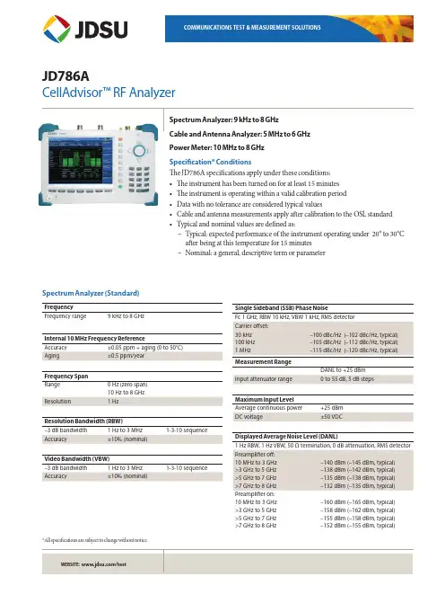
JD786ACellAdvisor™ RF AnalyzerSpectrum Analyzer: 9 kHz to 8 GHzCable and Antenna Analyzer: 5 MHz to 6 GHzPower Meter: 10 MHz to 8 GHzSpecification* ConditionsThe JD786A specifications apply under these conditions:• The instrument has been turned on for at least 15 minutes• The instrument is operating within a valid calibration period• Data with no tolerance are considered typical values• Cable and antenna measurements apply after calibration to the OSL standard• Typical and nominal values are defined as:–Typical: expected performance of the instrument operating under 20° to 30°Cafter being at this temperature for 15 minutes–Nominal: a general, descriptive term or parameterSpectrum Analyzer (Standard)FrequencyFrequency range 9 kHz to 8 GHzInternal 10 MHz Frequency ReferenceAccuracy ±0.05 ppm + aging (0 to 50°C)Aging±0.5 ppm/yearFrequency SpanRange 0 Hz (zero span)10 Hz to 8 GHzResolution 1 HzResolution Bandwidth (RBW)–3 dB bandwidth 1 Hz to 3 MHz 1-3-10 sequence Accuracy±10% (nominal)Video Bandwidth (VBW)–3 dB bandwidth 1 Hz to 3 MHz 1-3-10 sequence Accuracy±10% (nominal)Single Sideband (SSB) Phase NoiseFc 1 GHz, RBW 10 kHz, VBW 1 kHz, RMS detectorCarrier offset:30 kHz100 kHz1 MHz–100 dBc/Hz (–102 dBc/Hz, typical)–105 dBc/Hz (–112 dBc/Hz, typical)–115 dBc/Hz (–120 dBc/Hz, typical) Measurement RangeDANL to +25 dBmInput attenuator range 0 to 55 dB, 5 dB stepsMaximum Input LevelAverage continuous power +25 dBmDC voltage±50 VDCDisplayed Average Noise Level (DANL)1 Hz RBW, 1 Hz VBW, 50 Ω termination, 0 dB attenuation, RMS detector Preamplifier off:10 MHz to 3 GHz>3 GHz to 5 GHz>5 GHz to 7 GHz>7 GHz to 8 GHz–140 dBm (–145 dBm, typical)–138 dBm (–142 dBm, typical)–135 dBm (–138 dBm, typical)–132 dBm (–135 dBm, typical) Preamplifier on:10 MHz to 3 GHz>3 GHz to 5 GHz>5 GHz to 7 GHz>7 GHz to 8 GHz–160 dBm (–165 dBm, typical)–158 dBm (–162 dBm, typical)–155 dBm (–158 dBm, typical)–152 dBm (–155 dBm, typical)*All specifications are subject to change without notice.Display Range Log scale and units (10 divisions displayed) 1 to 20 dB/division in 1 dB steps dBm, dBV, dBmV, dBµV Linear scale and units (10 divisions displayed)V, mV, mW, WDetectors Normal, positive peak, sample, negative peak, RMS Number of traces 6Trace functionsClear/write, maximum hold, minimum hold, capture, load view on/offTotal Absolute Amplitude AccuracyPreamplifier off, power level >–50 dBm, auto-coupled 1 MHz to 8 GHz ±1.3 dB (±0.5 dB typical) Add ±1.0 dB 20°C to 30°C–10°C to 55°C after60-minute warm up Reference Level Setting range –120 to +100 dBm Setting resolution Log scale Linear scale0.1 dB1% of reference levelMarkers Marker types Normal, delta, delta pair, noise, frequency count marker Number of markers 6Marker functionsPeak, next peak, peak left, peak right, minimum search marker to center/start/stopRF Input VSWR 1 MHz to 8 GHz1.5:1 (typical)Atten >20 dBSecond Harmonic Distortion Mixer level = –25 dBm 50 MHz to 2.6 GHz <–65 dBc (typical) >2.6 GHz to 8 GHz<–70 dBc (typical)Third-Order Inter-Modulation (Third-order Intercept: TOI)200 MHz to 3 GHz +10 dBm (typical) >3 GHz to 8 GHz +12 dBm (typical)SpuriousInherent residual responseInput terminated, 0 dB attenuation, preamplifier off, RBW at 10 kHz –90 dBm (nominal)Exceptions –**************,1.95,2.57264,3.2, and4.5 GHz–*************.8GHzInput-related spurious <–70 dBc (nominal)Dynamic Range2/3 (TOI-DANL) in 1 Hz RBW >104 dB @ 2 GHzSweep Time Range 0.4 ms to 1000 s 24 µs to 200 sSpan = 0 Hz (zero span)Accuracy ±2%Span = 0 Hz (zero span)ModeContinuous, singleGated Sweep Trigger source External, video, and GPS Gate length 1 µs to 100 ms Gate delay 0 to 100 msTriggerTrigger source Free run, video, external Trigger delay Range Resolution0 to 200 s 6 µsMeasurements*Channel powerOccupied bandwidth Spectrum emission mask Adjacent channel power Spurious emissions Field strengthAM/FM audio demodulation Route map* CW signal generator (Option 003) can be set up simultaneously.Cable and Antenna Analyzer (Standard)Frequency Range 5 MHz to 6 GHz Resolution 10 kHz Accuracy ±1 ppmData Points126, 251, 501, 1001, 2001Measurement SpeedMeasurement Accuracy Corrected directivity 40 dB Reflection uncertainty ±(0.3 + |20log (1+10-EP/20)|) (typical)EP = directivity – measured return lossOutput PowerHigh 5 MHz to 5.5 GHz, 0 dBm (typical)5.5 GHz to 6 GHz, –5 dBm (typical) Low 5 MHz to 6 GHz, –30 dBm (typical) Dynamic RangeReflection 60 dBMaximum Input LevelAverage continuous power +25 dBm (nominal) DC voltage ±50 VDC Interference immunityOn channel On frequency +17 dBm @ >1.4 MHz from carrier frequency (nominal)0 dBm within ±10 kHz from the car-rier frequency (nominal)Measurements Reflection (VSWR)VSWR range Return loss range Resolution 1 to 650 to 60 dB 0.01Distance to Fault (DTF)Vertical VSWR range Vertical return loss range Vertical resolution Horizontal range Horizontal resolution 1 to 651 to 60 dB0.010 to (# of data points – 1) x horizontal resolution Maximum = 1500 m (4921 ft)(1.5 x 10⁸) x (VP)/(delta)V P = propagation velocityDelta = stop freq – start freq (Hz)Cable Loss (1-port)Range Resolution 0 to 30 dB 0.01 dB1-port PhaseRange Resolution –180° to +180° 0.01°Smith ChartResolution0.01RF Power Meter (Standard)General ParametersDisplay range –100 to +100 dBmOffset range0 to 60 dBResolution0.01 dB or 0.1xW (x = m, u, p) Internal RF Power SensorFrequency range 10 MHz to 6 GHzSpan 1 kHz to 100 MHz Dynamic range–120 to +25 dBm Maximum power+25 dBmAccuracy Same as spectrum analyzerExternal RF Power SensorsDirectional Power Sensor JD731BFrequency range300 MHz to 3.8 GHzDynamic range0.15 to 150 W (average)4 to 400 W (peak)Connector type Type-N female on both ends Measurement type Forward/reverse average power,forward peak power, VSWR Accuracy±(4% of reading + 0.05 W)1,2 Directional Power SensorFrequency rangeJD733A150 MHz to 3.5 GHzDynamic range0.1 to 50 W (average)0.1 to 50 W (peak) Connector type Type-N female on both ends Measurement type Forward/reverse average power,forward peak power, VSWR Accuracy±(4% of reading + 0.05 W)1,2 Terminating Power Sensor JD732BFrequency range20 MHz to 3.8 GHzDynamic range–30 to +20 dBmConnector type Type-N maleMeasurement type AverageAccuracy±7%1Terminating Power Sensor JD734BFrequency range20 MHz to 3.8 GHzDynamic range–30 to +20 dBmConnector type Type-N maleMeasurement type PeakAccuracy±7%1Terminating Power Sensor JD736BFrequency range20 MHz to 3.8 GHzDynamic range–30 to +20 dBmConnector type Type-N maleMeasurement type Average and PeakAccuracy±7%11. CW condition at 25°C ±10°C.2. Forward power.Optical Power Meter (Option 13)Optical Power MeterDisplay range –100 to +100 dBmOffset range0 to 60 dBResolution 0.01 dB or 0.1 mWExternal Optical Power SensorsOptical Power Sensor Wavelength range MP-60780 to 1650 nmMax permitted input level+10 dBmConnector input Universal 2.5 and 1.25 mm Accuracy±5%Optical Power Sensor Wavelength range MP-80780 to 1650 nmMax permitted input level+23 dBmConnector input Universal 2.5 and 1.25 mm Accuracy±5%2-Port T ransmission Measurements (Option 001) FrequencyFrequency range 5 MHz to 6 GHzFrequency resolution 10 kHzOutput PowerHigh 5 MHz to 5.5 GHz, 0 dBm (typical)5.5 GHz to 6 GHz, –5 dBm (typical) Low 5 MHz to 6 GHz, –30 dBm (typical) Measurement SpeedVector 1.6 ms/point (typical)Scalar 3.4 ms/point (typical) Dynamic RangeVector 5 MHz to 3 GHz, 80 dB>3 GHz to 6 GHz, 75 dB @average 5 @average 5Scalar 5 MHz to 4.5 GHz, >110 dB4.5 GHz to 6 GHz, >105 dB MeasurementsInsertion Loss/GainRange Resolution –120 to 100 dB 0.01 dB2-Port PhaseRange Resolution –180° to +180° 0.01°Bias-Tee (Option 002)VoltageVoltage range +12 to +32 V Voltage resolution 0.1 V Power8 W Max CW Signal Generator (Option 003)FrequencyFrequency range 25 MHz to 6 GHzFrequency reference±1 ppm maximumFrequency resolution10 kHzOutput PowerRange 5 MHz to 5.5 GHz, –60 to 0 dBm>5.5 to 6 GHz, –60 to –5 dBmStep 1 dBAccuracy±1.5 dB (20 to 30 °C)GPS Receiver and Antenna (Option 010)GPS IndicatorLatitude, longitude, altitudeHigh-Frequency AccuracySpectrum, interference, and signal analyzerGPS lock ±25 ppbHold over (for 3 days) ±50 ppb (0 to 50°C)15 minutes aftersatellite locked Connector SMA, femaleInterference Analyzer (Option 011)MeasurementsSpectrum analyzer Sound indicator, AM/FM audio demodulation,interference ID, spectrum recorder Spectrogram Collects up to 72 hours of dataRSSI Collects up to 72 hours of data Interference finderSpectrum replayerChannel Scanner (Option 012)Frequency Range1 MHz to 8 GHzMeasurement Range–110 to +25 dBmMeasurementsChannel scanner 1 to 20 channelsFrequency scanner 1 to 20 frequenciesCustom scanner 1 to 20 channels or frequenciesGeneral InformationInputs and OutputsRF in Spectrum analyzerConnector Impedance Damage level Type-N, female50 Ω (nominal)>+33 dBm, ±50 VDC (nominal), 3 minReflection/RF out Cable and antenna analyzerConnector Impedance Damage level Type-N, female50 Ω (nominal)>+40 dBm, ±50 VDC (nominal), 3 minRF in Cable and antenna analyzerConnector Impedance Maximum level Type-N, female50 Ω (nominal)>+25 dBm, ±50 VDC (nominal)External trigger, GPSConnector Impedance SMA, female 50 Ω (nominal)External refConnector Impedance Input frequency Input range SMA, female50 Ω (nominal)10 MHz, 13 MHz, 15 MHz –5 to +5 dBmUSBUSB host1 USB client2Type A, 1 port Type B, 1 portLAN RJ45, 10/100Base-TGPIO RJ45Audio jack 3.5 mm headphone jackExternal power 5.5 mm barrel connectorSpeaker Built-in speakerDisplayType Resistive touch screenSize8 inch, LED backlight, transflective LCDwith anti-glare coatingResolution800 x 600PowerExternal DC input 12 to 19 VDCPower consumption 37 W 49 W maximum(when charging battery)BatteryType10.8 V, 7800 mA/hr (Lithium ion) Operating time >3 hours (typical)Charge time 2.5 hours (80%), 5 hours (100%) Charging temperature0° to 45°C (32° to 104°F) ≤85% RH Discharging temperature–20° to 55°C (4° to 131°F) ≤85% RH Storage temperature30° to 25°C (32° to 77°F)≤85% RH (non-condensing)Data StorageInternal4Maximum 100 MBExternal5Limited by size of USB flash drive EnvironmentalOperating temperatureAC Power0° to 40°C (32° to 104°F) with no derating Battery0° to 40°C (32° to 104°F) @charging–10° to 55°C (14° to 131°F) @discharging Maximum humidity 85% RH (non-condensing)Shock and vibration MIL-PRF-28800F Class 2Storage temperature6–55° to 71°C (–67° to 160°F)EMCIEC/EN 61326-1:2006 (complies with European EMC)CISPR11:2009 +A1:2010ESDIEC/EN 61000-4-2Size and Weight (standard configuration)Weight (with battery)<4.3 kg (9.5 lb)Size (W x H x D)295 x 195 x 82 mm(11.6 x 7.7 x 3.2 in)Warranty2 yearsCalibration Cycle1 year1. Connects flash drive and power sensor.2. Connects to PC for data transfer.3. 20 to 85% RH, store battery pack in low-humidity environment.Extended exposure to temperature above 45°C could significantly degrade battery performance and life.4. Up to 3800 traces.5. Supports USB 2.0 compatible memory devices.6. With the battery pack removed.Optional Calibration KitsStandard JD786A9 kHz to 8 GHz Spectrum analyzer5 MHz to6 GHz Cable and antenna analyzer 110 MHz to 8 GHz RF power meter (internal mode)OptionsNOTE: Upgrade options for the JD786A use the designation JD786AU before the respective last three-digit option number.JD786A0012-Port Transmission Measurement 2JD786A002 Bias-Tee (requires optionJD786A001)JD786A003CW Signal Generator JD786A010GPS Receiver and Antenna JD786A011Interference Analyzer 3, 4JD786A012Channel Scanner JD786A013Optical Power Meter 5Standard AccessoriesG710550326AC/DC power adapter 6G710550335Cross LAN cable (1.5 m)6GC73050515USB A to B cable (1.8 m)6GC72450518>1 GB USB memory 6G710550325Rechargeable lithium ion battery 6G710550323Automotive cigarette lighter 12 VDC adapter 6G710550316Stylus pen 6JD780A361JD780A Series user’s manual and applicationsoftware — CD1. Requires calibration kit.2. Requires dual-port calibration kit.3. Highly recommend adding GPS receiver JD786A010.4. Highly recommend adding antennas G7*******x and/or G7*******x.5. Requires MP-60 or MP-80.6.Standard accessories can be purchased separately.Optional RF Power SensorsJD731B Directional Power Sensor (peak and average power)Frequency: 300 MHz to 3.8 GHzPower: average 0.15 to 150 W, peak 4 to 400 WJD733A Directional Power Sensor (peak and average power)Frequency: 150 MHz to 3.5 GHzPower: average/peak 0.1 to 50 WJD732B Terminating Power Sensor (average power)Frequency: 20 MHz to 3.8 GHzPower: –30 to +20 dBmJD734B Terminating Power Sensor (peak power)Frequency: 20 MHz to 3.8 GHzPower: –30 to +20 dBmJD736B Terminating Power Sensor (peak and average power) Frequency: 20 MHz to 3.8 GHzPower: –30 to +20 dBmOptional Optical Power SensorsMP-60 Miniature USB 2.0 Optical Power SensorWavelength Range: 780 to 1650 nm1300, 1310, 1490, 1550 nm: –50 to +10 dBm850 nm: –45 to +10 dBmMP-80 Miniature USB 2.0 Optical Power SensorWavelength range: 780 to 1650 nm1300, 1550 nm: –35 to +23 dBm850 nm: –30 to +23 dBm Optional RF AdaptersG710050570 Adapter Type-N(f) to Type-N(f), DC to 6 GHz, 50 ΩG710050571Adapter Type-N(m) to DIN(f), DC to 4 GHz, 50 ΩG710050572Adapter DIN(m) to DIN(m), DC to 4 GHz, 50 ΩG710050573Adapter Type-N(m) to SMA(f), DC to 18 GHz, 50 ΩG710050574Adapter Type-N(m) to BNC(f), DC to 1.5 GHz, 50 ΩG710050576Adapter Type-N(m) to DIN(m), DC to 4 GHz, 50 ΩG710050577Adapter Type-N(f) to DIN(f), DC to 4 GHz, 50 ΩG710050578Adapter Type-N(f) to DIN(m), DC to 4 GHz, 50 ΩG710050579Adapter DIN(f) to DIN(f), DC to 4 GHz, 50 Ω Optional MiscellaneousG710050581Attenuator 40 dB, 100 W, DC to 4 GHz(unidirectional)JD74050341Soft carrying caseJD71050342Hard carrying caseJD74050343Backpack carrying caseG710050585RF directional coupler, 700 MHz to 4 GHz, 30 dB,input/output; Type-N(m) to Type-N(f), tap off;Type-N(f)7G710050586RF Combiner, 700 MHz to 4 GHz, Type-N(f) toType-N(m)7G710550324External battery chargerJD780A362JD780A series user’s manual – printed version 7. Highly recommended for LTE testing.Test & Measurement Regional Sales。

Highlights:• 5 GbE interfaces in a desktop form factor • SD-Branch ready• Secure SD-WAN capability • SonicExpress App onboarding • Zero-Touch Deployment• Single-pane-of-glass-management through cloud or firewall • SonicWall Switch, SonicWave Access Point and Capture Client integration • Built-in and expandable storage • Redundant power • High port density • Cellular failover • SonicOS 7.0 • TLS 1.3 support• Groundbreaking performance • High connection count • Fast DPI performance • Low TCOSonicWall TZ570 /570W/570PThe SonicWall TZ570 series, available in three models (TZ570, TZ570W, TZ570P) is the first desktop-form-factor next-generation firewall (NGFW) with 5 Gigabit Ethernet interfaces.Designed for mid-sized organizations and distributed enterprise with SD-Branch locations, the TZ570 series delivers industry-validated security effectiveness with best-in-class price-performance. TZ570 NGFWs address the growing trends in web encryption, connected devices and high-speed mobility by delivering a solution that meets the need for automated, real-time breach detection and prevention. The TZ570 is highly scalable, with high port density of 10 ports. It features both in-built and anexpandable storage of up to 256GB, that enables various features including logging, reporting, caching, firmware backup and more. An optionalsecond power supply provides added redundancy in case of failure. Deployment of TZ570 is furthersimplified by Zero-Touch Deployment, with the ability to simultaneously roll out these devices across multiple locations with minimal IT support. Built on next-gen hardware, itintegrates firewalling, switching and wireless capabilities, plus provides integration with Capture Client for seamless endpoint security.SonicOS and Security ServicesThe SonicOS architecture is at the core of TZ NGFWs. TZ570 is powered by the feature rich SonicOS 7.0operating system with new modern looking UX/UI, advanced security, networking and managementcapabilities. TZ570 features integrated SD-WAN , TLS 1.3 support, real-time visualization, high-speed virtual private networking (VPN) and other robust security features.Unknown threats are sent to SonicWall’s cloud-based Capture Advanced Threat Protection (ATP) multiengine sandbox for analysis. Enhancing Capture ATP is our patent-pending Real-Time Deep Memory Inspection (RTDMI™) technology. As one of Capture ATP’s engine, RTDMI detects and blocks malware and zero-day threats by inspecting directly in memory.By leveraging Capture ATP with RTDMI technology, in addition tosecurity services such as Reassembly-Free Deep Packet Inspection (RFDPI), Anti-virus and Anti-spyware Protection, intrusion preventionsystem, Application Intelligence and Control, Content Filtering Services, DPI-SSL, TZ series firewalls stop malware, ransomware and otherDeploymentsSmall to Medium size Business• Save space and money with an integrated gateway security solution with firewalling, switching and wireless capabilities •Reduce complexity and get the business runningwithout relying on IT personnel with easy onboarding using SonicExpress App and Zero-Touch Deployment, and easy management through a single pane of glass • Attain business continuity by providing failover to cellular connectivity • Protect network from attacks with a comprehensive security solution that incorporates VPN, IPS, CFS, AV and much more • Leverage high port density to power on multiple PoE devices such as IP phones and IP cameras • Boost employee productivity by blockingunauthorized access with traffic segmentation and access policiesSonicWall SwitchZero-T ouch Deployment CapableSonicWave Access PointZero-T ouch Deployment CapableCamera IP PhoneLaptopSmartphoneCapture Client Access SecurityEndpoint SecurityD istributed Enterprise with SD-Branches• Enhance customer experience and adapt to the changing business needs by enabling next-gen branch connectivity with SD-Branch • Drive business growth by investing in next-genappliances with multi-gigabit and advanced security features, to future-proof against the changing network and security landscape • Secure networks from the most advanced attacks with advanced security features and automatically block threats on decrypted traffic using protocols such as TLS 1.3• Leverage end-to-end network security withseamless integration of SonicWave access points, SonicWall Switches and Capture Client • Ensure seamless communication as stores talk to HQ via easy VPN connectivity which allows IT administrators to create a hub and spoke configuration for the safe transport of data between all locations • Improve business efficiency, performance and reduce costs by leveraging TZ570’s hardware and software enhancements, plus features such SD-WAN technology • Scale quickly and effortlessly with SonicExpress App and Zero-Touch Deployment • Ensure business continuity by providing failover to cellular connectivity • Maintain compliance with security features, and leverage built-in and expandable storage to store logs for audit purposesIPSec VPN clients (maximum)10 (500)SSL VPN licenses (maximum) 2 (200)Encryption/authentication DES, 3DES, AES (128, 192, 256-bit)/MD5, SHA-1, Suite B CryptographyKey exchange Diffie Hellman Groups 1, 2, 5, 14vRoute-based VPN RIP, OSPF, BGPRoute-based VPN Verisign, Thawte, Cybertrust, RSA Keon, Entrust and Microsoft CA for SonicWall-to-SonicWall VPN, SCEPVPN featuresDead Peer Detection, DHCP Over VPN, IPSec NAT Traversal, Redundant VPN Gateway,Route-based VPNGlobal VPN client platforms supported Microsoft ® Windows 10NetExtender Microsoft ® Windows 10, LinuxMobile ConnectApple ® iOS, Mac OS X, Google ® Android ™, Kindle Fire, Chrome OS, Windows 10SonicWall TZ570/570W/570P specifications- WAN X1 and X2 Port LEDs - X0–X7 RJ45 Port LEDs- X8 / X9 SFP/SFP+ Port LEDsSuperSpeed PortsLEDs -Security LED-Storage LEDPower InputConsole PortSonicWall TZ570/570W/570P specifications, continuedContent Filtering Service (CFS)HTTP URL, HTTPS IP, keyword and content scanning, Comprehensive filtering basedon file types such as ActiveX, Java, Cookies for privacy, allow/forbid lists Comprehensive Anti-Spam Service YesApplication Visualization YesApplication Control YesCapture Advanced Threat Protection YesDNS SecurityYesMajor regulatory complianceFCC Class B, FCC , ICESClass B, CE (EMC, LVD,RoHS), C-Tick, VCCI ClassB, UL/cUL, TUV/GS, CB,Mexico DGN notice byUL, WEEE, REACH, BSMI,KCC/MSIP, ANATELFCC P15E, ICES Class B,ISED/IC, CE (RED, RoHS),C-Tick, VCCI Class B, JapanWireless, UL/cUL, TUV/GS,CB, Mexico DGN notice byUL, WEEE, REACH, BSMI,NCC (TW) KCC/MSIP,SRRC, ANATELFCC Class A, ICES ClassA, CE (EMC, LVD, RoHS),C-Tick, VCCI Class A, UL/cUL, TUV/ GS, CB, MexicoDGN notice by UL, WEEE,REACH, BSMI, KCC/MSIP,ANATELSonicWall TZ570W specifications, continuedFrequency bands802.11a: 5.180-5.825 GHz; 802.11b/g: 2.412-2.472 GHz; 802.11n: 2.412-2.472 GHz,5.180-5.825 GHz; 802.11ac: 5.180-5.825 GHzOperating channels 802.11a: US and Canada 12, Europe 11, Japan 4, Singapore4, Taiwan 4; 802.11b/g: US and Canada 1-11, Europe 1-13, Japan (14-802.11b only); 802.11n (2.4 GHz): US and Canada 1-11, Europe 1-13, Japan 1-13; 802.11n (5 GHz): US and Canada 36-48/149-165, Europe 36-48, Japan 36-48, Spain 36-48/52-64; 802.11ac: US and Canada 36-48/149-165, Europe 36-48, Japan 36-48, Spain 36-48/52-64Transmit output power Based on the regulatory domain specified by the system administrator Transmit power control YesData rates supported 802.11a: 6, 9, 12, 18, 24, 36, 48, 54 Mbps per channel; 802.11b: 1, 2, 5.5, 11 Mbps per channel; 802.11g: 6, 9, 12, 18, 24, 36, 48, 54 Mbps per channel; 802.11n: 7.2, 14.4, 21.7, 28.9, 43.3, 57.8, 65, 72.2, 15, 30, 45, 60, 90, 120, 135, 150 Mbps per channel; 802.11ac: 7.2, 14.4, 21.7, 28.9, 43.3, 57.8, 65, 72.2, 86.7, 96.3, 15, 30, 45, 60, 90, 120, 135, 150, 180, 200, 32.5, 65, 97.5, 130, 195, 260, 292.5, 325, 390, 433.3, 65, 130, 195, 260, 390, 520, 585, 650, 780, 866.7 Mbps per channelModulation technology spectrum802.11a: Orthogonal Frequency Division Multiplexing (OFDM); 802.11b: Direct Sequence Spread Spectrum (DSSS); 802.11g: Orthogonal Frequency Division Multiplexing (OFDM)/Direct Sequence Spread Spectrum (DSSS); 802.11n: Orthogonal Frequency Division Multiplexing (OFDM); 802.11ac: Orthogonal Frequency DivisionMultiplexing (OFDM)1. Testing Methodologies: Maximum performance based on RFC 2544 (for firewall). Actual performance may vary depending on network conditions and activated services.2. Threat Prevention/GatewayAV/Anti-Spyware/IPS throughput measured using industry standard Spirent WebAvalanche HTTP performance test and Ixia test tools. Testing done with multiple flows through multiple port pairs. Threat Prevention throughput measured with Gateway AV, Anti-Spyware, IPS and Application Control enabled.3. VPN throughput measured using UDP traffic at 1280 byte packet size adhering to RFC 2544. All specifications, features and availability are subject to change.4. For rack mount, separate rack mount kit available.5. All TZ integrated wireless models can support either 2.4GHz or 5GHz band. For dual-band support, please use SonicWall's wireless access point products.SonicOS 7.0 Feature SummaryFirewall• Stateful packet inspection• Reassembly-Free Deep Packet Inspection • DDoS attack protection (UDP/ICMP/SYN flood)• IPv4/IPv6 support• Biometric authentication for remote access • DNS proxy• Full API support• SonicWall Switch integration• SD-WAN scalability• SD-WAN Usability Wizard1• SonicCoreX and SonicOS containerization1• Connections scalability (SPI, DPI, DPI SSL) Enhanced dashboard1• Enhanced device view• Top traffic and user summary• Insights to threats• Notification centerTLS/SSL/SSH decryption and inspection• TLS 1.3 with enhanced security1• Deep packet inspection for TLS/SSL/SSH • Inclusion/exclusion of objects, groupsor hostnames• SSL control• Enhancements for DPI-SSL with CFS• Granular DPI SSL controls per zone or rule Capture advanced threat protection2• Real-Time Deep Memory Inspection• Cloud-based multi-engine analysis• Virtualized sandboxing• Hypervisor level analysis• Full system emulation• Broad file type examination• Automated and manual submission• Real-time threat intelligence updates• Block until verdict• Capture ClientIntrusion prevention2• Signature-based scanning• Automatic signature updates• Bi-directional inspection• Granular IPS rule capability• GeoIP enforcement• Botnet filtering with dynamic list• Regular expression matchingAnti-malware2• Stream-based malware scanning• Gateway anti-virus• Gateway anti-spyware• Bi-directional inspection• No file size limitation• Cloud malware databaseApplication identification2• Application control• Application bandwidth management• Custom application signature creation• Data leakage prevention• Application reporting over NetFlow/IPFIX• Comprehensive application signature databaseTraffic visualization and analytics• User activity• Application/bandwidth/threat usage• Cloud-based analyticsHTTP/HTTPS Web content filtering2• URL filtering• Proxy avoidance• Keyword blocking• Policy-based filtering (exclusion/inclusion)• HTTP header insertion• Bandwidth manage CFS rating categories• Unified policy model with app control• Content Filtering ClientVPN• Secure SD-WAN• Auto-provision VPN• IPSec VPN for site-to-site connectivity• SSL VPN and IPSec client remote access• Redundant VPN gateway• Mobile Connect for iOS, Mac OS X, Windows,Chrome, Android and Kindle Fire• Route-based VPN (OSPF, RIP, BGP)Networking• PortShield• Jumbo frames• Path MTU discovery• Enhanced logging• VLAN trunking• Port mirroring (NS a 2650 and above)• Layer-2 QoS• Port security• Dynamic routing (RIP/OSPF/BGP)• SonicWall wireless controller• Policy-based routing (ToS/metric and ECMP)• NAT• DHCP server• Bandwidth management• A/P high availability with state sync• Inbound/outbound load balancing• High availability - Active/Standby withstate sync• L2 bridge, wire/virtual wire mode, tap mode,NAT mode• Asymmetric routing• Common Access Card (CAC) supportVoIP• Granular QoS control• Bandwidth management• DPI for VoIP traffic• H.323 gatekeeper and SIP proxy supportManagement, monitoring and support• Capture Security Appliance (CS a) support• Capture Threat Assessment (CTA) v2.0• New design or template• Industry and global average comparison• New UI/UX, Intuitive feature layout1• Dashboard• Device information, application, threats• Topology view• Simplified policy creation and management• Policy/Objects usage statistics1• Used vs Un-used• Active vs Inactive• Global search for static data• Storage support1• Internal and external storage management1• WWAN USB card support (5G/LTE/4G/3G)• Network Security Manager (NSM) support• Web GUI• Command line interface (CLI)• Zero-Touch registration & provisioning• CSC Simple Reporting1• SonicExpress mobile app support• SNMPv2/v3• Centralized management and reporting withSonicWall Global Management System (GMS)2• Logging• Netflow/IPFix exporting• Cloud-based configuration backup• BlueCoat security analytics platform• Application and bandwidth visualization• IPv4 and IPv6 management• CD management screen• Dell N-Series and X-Series switchmanagement including cascaded switchesDebugging and diagnostics• Enhanced packet monitoring• SSH terminal on UIWireless• SonicWave AP cloud management• WIDS/WIPS• Rogue AP prevention• Fast roaming (802.11k/r/v)• 802.11s mesh networking• Auto-channel selection• RF spectrum analysis• Floor plan view• Topology view• Band steering• Beamforming• AirTime fairness• Bluetooth Low Energy• MiFi extender• RF enhancements and improvements• Guest cyclic quotaIntegrated Wireless (TZ570W only)• 802.11ac Wave 2 wireless• Dual-band (2.4 GHz and 5.0 GHz)• 802.11 a/b/g/n/ac wireless standards• Wireless intrusion detection and prevention• Wireless guest services• Lightweight hotspot messaging• Virtual access point segmentation• Captive portal• Cloud ACLProduct SKUTZ570 with 1-year TotalSecure Essential Edition02-SSC-5651 TZ570W with 1-year TotalSecure Essential Edition02-SSC-5649 TZ570P with 1-year TotalSecure Essential Edition02-SSC-5653 TZ570 High Availability02-SSC-5694 TZ570P High Availability02-SSC-5655 TZ570 with 3-year Secure Upgrade Plus Essential Edition02-SSC-5661 TZ570W with 3-year Secure Upgrade Plus Essential Edition 02-SSC-5663 TZ570P with 3-year Secure Upgrade Plus Essential Edition02-SSC-5667Services for SonicWall TZ570SKU Essential Protection Service Suite - Capture ATP, Threat Prevention, Content Filtering, Anti-Spam and 24x7 Support (1-year)02-SSC-5137 Capture Advanced Threat Protection for TZ570 (1-year)02-SSC-5083 Gateway Anti-Virus, Intrusion Prevention and Application Control (1-year)02-SSC-5155 Content Filtering Service (1-year)02-SSC-5119 Comprehensive Anti-Spam Service (1-year)02-SSC-5101 24x7 Support (1-year)02-SSC-5065Services for SonicWall TZ570W SKU Essential Protection Service Suite - Capture ATP, Threat Prevention, Content Filtering, Anti-Spam and 24x7 Support (1-year)02-SSC-5149 Capture Advanced Threat Protection for TZ570W (1-year)02-SSC-5095 Gateway Anti-Virus, Intrusion Prevention and Application Control (1-year)02-SSC-5167 Content Filtering Service (1-year)02-SSC-5131 Comprehensive Anti-Spam Service (1-year)02-SSC-5113 24x7 Support (1-year)02-SSC-5077Services for SonicWall TZ570P SKU Essential Protection Service Suite - Capture ATP, Threat Prevention, Content Filtering, Anti-Spam and 24x7 Support (1-year)02-SSC-5143 Capture Advanced Threat Protection for TZ570P (1-year)02-SSC-5089 Gateway Anti-Virus, Intrusion Prevention and Application Control (1-year)02-SSC-5161 Content Filtering Service (1-year)02-SSC-5125 Comprehensive Anti-Spam Service (1-year)02-SSC-5107 24x7 Support (1-year)02-SSC-5071Accessories SKU SonicWall TZ670/570 Series FRU Power Supply02-SSC-3078 SonicWall TZ670/570 Series Rack Mount Kit02-SSC-3112 SonicWall 32GB Storage Module for TZ670/570 Series02-SSC-3114 SonicWall 64GB Storage Module for TZ670/570 Series02-SSC-3115 SonicWall 128GB Storage Module for TZ670/570 Series02-SSC-3116 SonicWall 256GB Storage Module for TZ670/570 Series02-SSC-3117 SonicWall Micro USB Console Cable for TZ670/570 Series02-SSC-5173 10GB-SR SFP+ Short Reach Fiber Module Multi-Mode No Cable01-SSC-9785 10GB-LR SFP+ Long Reach Fiber Module Single-Mode No Cable01-SSC-9786 10GB SFP+ Copper with 1M Twinax Cable01-SSC-9787 10GB SFP+ Copper with 3M Twinax Cable01-SSC-9788 1GB-SX SFP Short Haul Fiber Module Multi-Mode No Cable01-SSC-9789 1GB-LX SFP Long Haul Fiber Module Single-Mode No Cable01-SSC-9790 1GB-RJ45 SFP Copper Module No Cable01-SSC-9791 SonicWall SFP+ 10GBASE-T Transceiver Copper RJ45 Module02-SSC-1874Regulatory model numbersTZ570APL62-0F7 TZ570W APL62-0F8 TZ570P APL63-0F9About SonicWallSonicWall delivers Boundless Cybersecurity for the hyper-distributed era and a work reality where everyone is remote, mobile and unsecure. By knowing the unknown, providing real-time visibility and enabling breakthrough economics, SonicWall closes the cybersecurity business gap for enterprises, governments and SMBs worldwide. For more information, visit .。

Dynamic topology:As the channel of communicationchanges, some of the neighbors who were reachable on theprevious channel might not be reachable on the currentchannel and vice versa. As a result the topology of the network changes with the change in frequency of operation resulting in route failures and packet loss.Heterogeneity:Different channels may support differenttransmission ranges, data rates and delay characteristics.Spectrum-Handoff delay:For each transition from onechannel to another channel due to the PU’s activity, thereis a delay involved in the transition called Spectrum- Handoff delay.All these factors decrease the predictability of the cause oftransit-delay and subsequent packet loss on the network. Thetime latency during channel hand-off in cognitive networksmight cause the TCP round trip timer to time out. TCP willwrongly recognize the delays and losses due to the abovefactors as network congestion and immediately take steps toreduce the congestion window size knowing not the cause ofpacket delay. This reduces the efficiency of the protocol insuch environments.动态技术:随着信道通信的变化,一些邻进信道的用户在原信道没有发生变化而在新信道发生变化,或者相反。
第20卷第12期装备环境工程2023年12月EQUIPMENT ENVIRONMENTAL ENGINEERING·135·冲击环境后峰锯齿脉冲试验条件自动寻优方法陈江攀,刘艳,王增凯,刘艺,孙立敏(北京电子工程总体研究所,北京 100854)摘要:目的通过自动寻优制定冲击环境后峰锯齿脉冲试验条件,避免冲击“过试验”。
方法根据冲击响应谱的基本原理和谱型特征,提出利用对数距离量化评价2条谱型的吻合度。
对冲击环境和后峰锯齿脉冲分别进行冲击响应谱分析,将2条冲击响应谱之间的对数距离最小作为优化目标,将后峰锯齿脉冲的波形参数作为优化参数,基于自适应差分进化算法,提出冲击环境后峰锯齿脉冲试验条件自动寻优方法。
结果将所提方法分别应用于模拟冲击环境和实测冲击环境,均获得了合理的后峰锯齿脉冲试验条件,验证了所提方法的正确性。
结论提出的基于自适应差分进化算法的冲击环境后峰锯齿脉冲试验条件自动寻优方法正确可行。
关键词:冲击环境;后峰锯齿脉冲;冲击响应谱;自适应差分进化算法;自动寻优中图分类号:TJ760;V416.5 文献标识码:A 文章编号:1672-9242(2023)12-0135-07DOI:10.7643/ issn.1672-9242.2023.12.017Automatic Optimization Method for Terminal Peak Sawtooth ShockPulse Test Conditions of Shock EnvironmentCHEN Jiang-pan, LIU Yan, WANG Zeng-kai, LIU Yi, SUN Li-min(Beijing Institute of Electronic System Engineering, Beijing 100854, China)ABSTRACT: The work aims to propose an automatic optimization method for terminal peak sawtooth shock pulse test condi-tions of shock environment to avoid "over-test". Firstly, the logarithmic distance was proposed to quantitatively evaluate the goodness of fit between two shock response spectra according to both the basic principle and spectrum characteristics of shock response spectra. Secondly, shock response spectrum analysis was carried out on both the shock environment and the terminal peak sawtooth shock pulse. According to the analysis results obtained, via setting the logarithmic distance between the two spec-tra as the optimization goal and the wave parameters of terminal peak sawtooth shock pulse as the optimization parameters, the automatic optimization method for terminal peak sawtooth shock pulse test conditions of shock environment was established based on adaptive differential evolution algorithm. The proposed method was applied in a simulated shock environment and a measured shock environment respectively. The reasonable terminal peak sawtooth shock pulse test conditions obtained verified the correctness of the method proposed. As a consequence, the proposed automatic optimization method for terminal peak sawtooth pulse test conditions in shock environments based on adaptive differential evolution algorithm is correct and feasible.KEY WORDS: shock environment; terminal peak sawtooth shock pulse; shock response spectrum; adaptive differ-收稿日期:2023-08-02;修订日期:2023-09-17Received:2023-08-02;Revised:2023-09-17基金项目:中国航天科工集团第二研究院质量与技术基础自筹资金项目(E23A013)Fund:Quality and Technology Foundation Self-financing Project of the Second Academy of CASIC (E23A013)引文格式:陈江攀, 刘艳, 王增凯, 等. 冲击环境后峰锯齿脉冲试验条件自动寻优方法[J]. 装备环境工程, 2023, 20(12): 135-141.CHEN Jiang-pan, LIU Yan, WANG Zeng-kai, et al. Automatic Optimization Method for Terminal Peak Sawtooth Shock Pulse Test Conditions of Shock Environment[J]. Equipment Environmental Engineering, 2023, 20(12): 135-141.·136·装备环境工程 2023年12月ential evolution algorithm; automatic optimization导弹装备在研制、生产、运输、发射、飞行等过程中,将会经受多种复杂冲击环境作用,包括运输跌落、弹射冲击、点火冲击、分离冲击、着陆冲击等。
NeXt generation/dynamic spectrum access/cognitiveradio wireless networks:A surveyIan F.Akyildiz,Won-Yeol Lee,Mehmet C.Vuran *,Shantidev MohantyBroadband and Wireless Networking Laboratory,School of Electrical and Computer Engineering,Georgia Institute of Technology,Atlanta,GA 30332,United StatesReceived 2January 2006;accepted 2May 2006Available online 17May 2006Responsible Editor:I.F.AkyildizAbstractToday’s wireless networks are characterized by a fixed spectrum assignment policy.However,a large portion of the assigned spectrum is used sporadically and geographical variations in the utilization of assigned spectrum ranges from 15%to 85%with a high variance in time.The limited available spectrum and the inefficiency in the spectrum usage neces-sitate a new communication paradigm to exploit the existing wireless spectrum opportunistically.This new networking paradigm is referred to as NeXt Generation (xG)Networks as well as Dynamic Spectrum Access (DSA)and cognitive radio networks.The term xG networks is used throughout the paper.The novel functionalities and current research chal-lenges of the xG networks are explained in detail.More specifically,a brief overview of the cognitive radio technology is provided and the xG network architecture is introduced.Moreover,the xG network functions such as spectrum manage-ment,spectrum mobility and spectrum sharing are explained in detail.The influence of these functions on the performance of the upper layer protocols such as routing and transport are investigated and open research issues in these areas are also outlined.Finally,the cross-layer design challenges in xG networks are discussed.Ó2006Elsevier B.V.All rights reserved.Keywords:Next generation networks;Dynamic spectrum access networks;Cognitive radio networks;Spectrum sensing;Spectrum management;Spectrum mobility;Spectrum sharing1.IntroductionToday’s wireless networks are regulated by a fixed spectrum assignment policy,i.e.the spectrumis regulated by governmental agencies and is assigned to license holders or services on a long term basis for large geographical regions.In addition,a large portion of the assigned spectrum is used spo-radically as illustrated in Fig.1,where the signal strength distribution over a large portion of the wireless spectrum is shown.The spectrum usage is concentrated on certain portions of the spectrum while a significant amount of the spectrum remains unutilized.According to Federal Communications1389-1286/$-see front matter Ó2006Elsevier B.V.All rights reserved.doi:10.1016/net.2006.05.001*Corresponding author.Tel.:+14048945141;fax:+14048947883.E-mail addresses:ian@ (I.F.Akyildiz),wylee@ (W.-Y.Lee),mcvuran@ (M.C.Vuran),shanti@ (S.Mohanty).Computer Networks 50(2006)2127–2159/locate/comnetCommission (FCC)[20],temporal and geographical variations in the utilization of the assigned spectrum range from 15%to 85%.Although the fixed spec-trum assignment policy generally served well in the past,there is a dramatic increase in the access to the limited spectrum for mobile services in the recent years.This increase is straining the effective-ness of the traditional spectrum policies.The limited available spectrum and the inefficiency in the spectrum usage necessitate a new communi-cation paradigm to exploit the existing wireless spec-trum opportunistically [3].Dynamic spectrum access is proposed to solve these current spectrum ineffi-ciency problems.DARPAs approach on Dynamic Spectrum Access network,the so-called NeXt Gener-ation (xG)program aims to implement the policy based intelligent radios known as cognitive radios [67,68].NeXt Generation (xG)communication net-works,also known as Dynamic Spectrum Access Networks (DSANs)as well as cognitive radio net-works,will provide high bandwidth to mobile users via heterogeneous wireless architectures and dynamic spectrum access techniques.The inefficient usage of the existing spectrum can be improved through opportunistic access to the licensed bands without interfering with the existing users.xG net-works,however,impose several research challenges due to the broad range of available spectrum as well as diverse Quality-of-Service (QoS)requirements of applications.These heterogeneities must be cap-tured and handled dynamically as mobile terminals roam between wireless architectures and along the available spectrum pool.The key enabling technology of xG networks is the cognitive radio.Cognitive radio techniques pro-vide the capability to use or share the spectrum inan opportunistic manner.Dynamic spectrum access techniques allow the cognitive radio to operate in the best available channel .More specifically,the cog-nitive radio technology will enable the users to (1)determine which portions of the spectrum is avail-able and detect the presence of licensed users when a user operates in a licensed band (spectrum sens-ing ),(2)select the best available channel (spectrum management ),(3)coordinate access to this channel with other users (spectrum sharing ),and (4)vacate the channel when a licensed user is detected (spec-trum mobility ).Once a cognitive radio supports the capability to select the best available channel,the next challenge is to make the network protocols adaptive to the available spectrum.Hence,new functionalities are required in an xG network to support this adaptivity.In summary,the main functions for cognitive radios in xG networks can be summarized as follows:•Spectrum sensing :Detecting unused spectrum and sharing the spectrum without harmful inter-ference with other users.•Spectrum management :Capturing the best avail-able spectrum to meet user communication requirements.•Spectrum mobility :Maintaining seamless com-munication requirements during the transition to better spectrum.•Spectrum sharing :Providing the fair spectrum scheduling method among coexisting xG users.These functionalities of xG networks enable spec-trum-aware communication protocols.However,the dynamic use of the spectrum causes adverse effects on the performance of conventional commu-nication protocols,which were developed consider-ing a fixed frequency band for communication.So far,networking in xG networks is an unexplored topic.In this paper,we also capture the intrinsic challenges for networking in xG networks and lay out guidelines for further research in this area.More specifically,we overview the recent proposals for spectrum sharing and routing in xG networks as well as the challenges for transport protocols.More-over,the effect of cross-layer design is addressed for communication in xG networks.The xG network communication components and their interactions are illustrated in Fig.2.It is evident from the significant number of interactions that the xG network functionalities necessitate a cross-layer design approach.More specifically,spec-Fig.1.Spectrum utilization.2128I.F.Akyildiz et al./Computer Networks 50(2006)2127–2159trum sensing and spectrum sharing cooperate with each other to enhance spectrum efficiency.In spec-trum management and spectrum mobility functions, application,transport,routing,medium access and physical layer functionalities are carried out in a cooperative way,considering the dynamic natureunderlying spectrum.paper presents a definition,functions andresearch challenges of the xG networks.InSection2,we provide a brief overview of the cognitiveradio technology.The xG network architectures onlicensed band and on unlicensed band are presentedin Section3.In Section4,we explain the existingwork and challenges in spectrum sensing.Then,wedescribe the xG network functionalities:spectrummanagement,spectrum mobility and spectrum shar-ing in Sections5,6,and7,respectively.In Section8,the perfor-i.e.,routingand transport.Finally,we explain how xG functionscan be implemented in a cross-layer approach in Sec-tion9and conclude the paper in Section10.2.Cognitive radioCognitive radio technology is the key technologythat enables an xG network to use spectrum in adynamic manner.The term,cognitive radio,canformally be defined as follows[20]:‘‘Cognitive Radio’’is a radio that can change itstransmitter parameters based on interaction withthe environment in which it operates.From this definition,two main characteristics ofthe cognitive radio can be defined[27,58]:•Cognitive capability:Cognitive capability refersto the ability of the radio technology to captureor sense the information from its radio environ-ment.This capability cannot simply be realizedby monitoring the power in some frequency bandof interest but more sophisticated techniques arerequired in order to capture the temporal andspatial variations in the radio environment andavoid interference to other users.Through thiscapability,the portions of the spectrum thatare unused at a specific time or location can beidentified.Consequently,the best spectrumand appropriate operating parameters can beselected.•Reconfigurability:The cognitive capability pro-vides spectrum awareness whereas reconfigu-rability enables the radio to be dynamicallyprogrammed according to the radio environ-ment.More specifically,the cognitive radio canbe programmed to transmit and receive on avariety of frequencies and to use different trans-mission access technologies supported by itshardware design[34].I.F.Akyildiz et al./Computer Networks50(2006)2127–21592129The cognitive radio concept wasfirst introduced in[45,46],where the main focus was on the radio knowledge representation language(RKRL)and how the cognitive radio can enhance theflexibility of personal wireless services.The cognitive radio is regarded as a small part of the physical world to use and provide information from environment.The ultimate objective of the cognitive radio is to obtain the best available spectrum through cogni-tive capability and reconfigurability as described before.Since most of the spectrum is already assigned,the most important challenge is to share the licensed spectrum without interfering with the transmission of other licensed users as illustrated in Fig.3.The cognitive radio enables the usage of temporally unused spectrum,which is referred to as spectrum hole or white space[27].If this band is further used by a licensed user,the cognitive radio moves to another spectrum hole or stays in the same band,altering its transmission power level or mod-ulation scheme to avoid interference as shown in Fig.3.In the following subsections,we describe the physical architecture,cognitive functions and recon-figurability capabilities of the cognitive radio technology.2.1.Physical architecture of the cognitive radioA generic architecture of a cognitive radio trans-ceiver is shown in Fig.4(a)[34].The main compo-nents of a cognitive radio transceiver are the radio front-end and the baseband processing unit.Each component can be reconfigured via a controlbus2130I.F.Akyildiz et al./Computer Networks50(2006)2127–2159to adapt to the time-varying RF environment.In the RF front-end,the received signal is amplified,mixed and A/D converted.In the baseband process-ing unit,the signal is modulated/demodulated and encoded/decoded.The baseband processing unit of a cognitive radio is essentially similar to existing transceivers.However,the novelty of the cognitive radio is the RF front-end.Hence,next,we focus on the RF front-end of the cognitive radios.The novel characteristic of cognitive radio trans-ceiver is a wideband sensing capability of the RF front-end.This function is mainly related to RF hardware technologies such aspower amplifier,and adaptive for the cognitiveradio should be capable of tuning to any part of a large range of frequency spectrum.Also such spectrum sensing enables real-time measurements of spectrum information from radio environment.Generally,a wideband front-end archi-tecture for the cognitive radio has the following struc-ture as shown in Fig.4(b)[12].The components of a cognitive radio RF front-end are as follows:•RF filter :The RF filter selects the desired band by bandpass filtering the received RF signal.•Low noise amplifier (LNA):The LNA amplifies the desired signal while simultaneously minimiz-ing noise component.•Mixer :In the mixer,the received signal is mixed with locally generated RF frequency and con-verted to the baseband or the intermediate fre-quency (IF).•Voltage-controlled oscillator (VCO):The VCO generates a signal at a specific frequency for a given voltage to mix with the incoming signal.This procedure converts the incoming signal to baseband or an intermediate frequency.•Phase locked loop (PLL):The PLL ensures that a signal is locked on a specific frequency and can also be used to generate precise frequencies with fine resolution.•Channel selection filter :The channel selection fil-ter is used to select the desired channel and to reject the adjacent channels.There are two types of channel selection filters [52].The direct conver-sion receiver uses a low-pass filter for the channel selection.On the other hand,the superheterodyne receiver adopts a bandpass filter.•Automatic gain control (AGC):The AGC main-tains the gain or output power level of an ampli-fier constant over a wide range of input signal levels.In this architecture,a wideband signal is received through the RF front-end,sampled by the high speed analog-to-digital (A/D)converter,and mea-surements are performed for the detection of the licensed user signal.However,there exist some limi-tations on developing the cognitive radio front-end.The wideband RF antenna receives signals from var-ious transmitters operating at different power levels,bandwidths,and locations.As a result,the RF front-end should have the capability to detect a weak sig-nal in a large dynamic range.However,this capabil-ity requires a multi-GHz speed A/D converter with high resolution,which might be infeasible [12,13].The requirement of a multi-GHz speed A/D con-verter necessitates the dynamic range of the signal to be reduced before A/D conversion.This reduction can be filtering strong signals.Since strong signals located anywhere in the wide spectrum notch filters are required for the reduction [12].Another approach is to use multiple antennas such that signal filtering is per-formed in the spatial domain rather than in the fre-quency domain.Multiple antennas can receive signals selectively using beamforming techniques [13].As explained previously,the key challenge of the physical architecture of the cognitive radio is an accurate detection of weak signals of licensed users over a wide spectrum range.Hence,the implementa-tion of RF wideband front-end and A/D converter are critical issues in xG networks.2.2.Cognitive capabilityThe cognitive capability of a cognitive radio enables real time interaction with its environment to determine appropriate communication parame-ters and adapt to the dynamic radio environment.The tasks required for adaptive operation in open spectrum are shown in Fig.5[27,46,58],which is referred to as the cognitive cycle .In this section,we provide an overview of the three main steps of the cognitive cycle:spectrum sensing ,spectrum anal-ysis ,and spectrum decision .The details and the related work of these functions are described in Sec-tions 4and 5.The steps of the cognitive cycle as shown in Fig.5are as follows:1.Spectrum sensing :A cognitive radio monitors the available spectrum bands,captures their infor-mation,and then detects the spectrum holes.I.F.Akyildiz et al./Computer Networks 50(2006)2127–215921312.Spectrum analysis:The characteristics of thespectrum holes that are detected through spec-trum sensing are estimated.3.Spectrum decision:A cognitive radio determinesthe data rate,the transmission mode,and the bandwidth of the transmission.Then,the appro-priate spectrum band is chosen according to the spectrum characteristics and user requirements.Once the operating spectrum band is determined, the communication can be performed over this spec-trum band.However,since the radio environment changes over time and space,the cognitive radio should keep track of the changes of the radio envi-ronment.If the current spectrum band in use becomes unavailable,the spectrum mobility function that will be explained in Section6,is performed to provide a seamless transmission.Any environmen-tal change during the transmission such as primary user appearance,user movement,or traffic variation can trigger this adjustment.2.3.ReconfigurabilityReconfigurability is the capability of adjusting operating parameters for the transmission on the fly without any modifications on the hardware com-ponents.This capability enables the cognitive radio to adapt easily to the dynamic radio environment. There are several reconfigurable parameters that can be incorporated into the cognitive radio[20] as explained below:•Operating frequency:A cognitive radio is capable of changing the operating frequency.Based on the information about the radio environment,the most suitable operating frequency can be determined and the communication can be dynamically performed on this appropriate oper-ating frequency.•Modulation:A cognitive radio should reconfigure the modulation scheme adaptive to the user requirements and channel conditions.For exam-ple,in the case of delay sensitive applications,the data rate is more important than the error rate.Thus,the modulation scheme that enables the higher spectral efficiency should be selected.Con-versely,the loss-sensitive applications focus on the error rate,which necessitate modulation schemes with low bit error rate.•Transmission power:Transmission power can be reconfigured within the power constraints.Power control enables dynamic transmission power con-figuration within the permissible power limit.If higher power operation is not necessary,the cog-nitive radio reduces the transmitter power to a lower level to allow more users to share the spec-trum and to decrease the interference.•Communication technology:A cognitive radio can also be used to provide interoperability among different communication systems.The transmission parameters of a cognitive radio can be reconfigured not only at the beginning of a transmission but also during the transmission. According to the spectrum characteristics,these parameters can be reconfigured such that the cognitive radio is switched to a different spectrum band,the transmitter and receiver parameters are reconfigured and the appropriate communication protocol parameters and modulation schemes are used.3.The xG network architectureExisting wireless network architectures employ heterogeneity in terms of both spectrum policies and communication technologies[3].Moreover, some portion of the wireless spectrum is already licensed to different purposes while some bands remain unlicensed.For the development of commu-nication protocols,a clear description of the xG net-work architecture is essential.In this section,the xG network architecture is presented such that all pos-sible scenarios are considered.The components of the xG network architecture, as shown in Fig.6,can be classified in two groups as the primary network and the xG network.Thebasic 2132I.F.Akyildiz et al./Computer Networks50(2006)2127–2159elements of the primary and the xG network are defined as follows:•Primary network :An existing network infrastruc-ture is generally referred to as the primary net-work,which has an exclusive right to a certain spectrum band.Examples include the common cellular and TV broadcast networks.The compo-nents of the primary network are as follows:–Primary user :Primary user (or licensed user)has a license to operate in a certain spectrum band.This access can only be controlled by the primary base-station and should not be affected by the operations of any other unli-censed users.Primary users do not need any modification or additional functions for coex-istence with xG base-stations and xG users.–Primary base-station :Primary base-station (or licensed base-station)is a fixed infrastructure network component which has a spectrum license such as base-station transceiver system (BTS)in a cellular system.In principle,the primary base-station does not have any xG capability for sharing spectrum with xG users.However,the primary base-station may be requested to have both legacy and xG proto-cols for the primary network access of xG users,which is explained below.•xG network :xG network (or cognitive radio net-work,Dynamic Spectrum Access network,sec-ondary network,unlicensed network)does not have license to operate in a desired band.Hence,the spectrum access is allowed only in an oppor-tunistic manner.xG networks can be deployed both as an infrastructure network and an ad hoc network as shown in Fig.6.The components of an xG network are as follows:–xG user :xG user (or unlicensed user,cognitive radio user,secondary user)has no spectrum license.Hence,additional functionalities are required to share the licensed spectrum band.–xG base-station :xG base-station (or unli-censed base-station,secondary base-station)is a fixed infrastructure component with xG capabilities.xG base-station provides single hop connection to xG users without spectrum access license.Through this connection,an xG user can access other networks.–Spectrum broker :Spectrum broker (or sched-uling server)is a central network entity that plays a role in sharing the spectrum resources among different xG networks.SpectrumFig.6.xG network architecture.I.F.Akyildiz et al./Computer Networks 50(2006)2127–21592133broker can be connected to each network andcan serve as a spectrum information managerto enable coexistence of multiple xG networks[10,32,70].The reference xG network architecture is shown in Fig.6,which consists of different types of net-works:a primary network,an infrastructure based xG network,and an ad-hoc xG network.xG net-works are operated under the mixed spectrum envi-ronment that consists of both licensed and unlicensed bands.Also,xG users can either commu-nicate with each other in a multihop manner oraccess the base-station.Thus,in xG networks,there are three different access types as explained next:•xG network access:xG users can access their own xG base-station both on licensed and unlicensed spectrum bands.•xG ad hoc access:xG users can communicate with other xG users through ad hoc connection on both licensed and unlicensed spectrum bands.•Primary network access:The xG users can also access the primary base-station through the licensed band.According to the reference architecture shown in Fig.6,various functionalities are required to sup-port the heterogeneity in xG networks.In Section 3.1,we describe the xG network functions to sup-port the heterogeneity of the network environment. Moreover,in Sections3.2and3.3,we overview xG network applications and existing architectures.3.1.xG network functionsAs explained before,xG network can operate in both licensed and unlicensed bands.Hence,the func-tionalities required for xG networks vary according to whether the spectrum is licensed or unlicensed. Accordingly,in this section,we classify the xG net-work operations as xG network on licensed band and xG network on unlicensed band.The xG network functions are explained in the following sections according to this classification.3.1.1.xG network on licensed bandAs shown in Fig.1,there exist temporally unused spectrum holes in the licensed spectrum band. Hence,xG networks can be deployed to exploit these spectrum holes through cognitive communi-cation techniques.This architecture is depicted in Fig.7,where the xG network coexists with the pri-mary network at the same location and on the same spectrum band.There are various challenges for xG networks on licensed band due to the existence of the primary users.Although the main purpose of the xG net-work is to determine the best available spectrum, xG functions in the licensed band are mainly aimed at the detection of the presence of primary users. The channel capacity of the spectrum holes depends on the interference at the nearby primary users. Thus,the interference avoidance with primary users is the most important issue in this architecture. Furthermore,if primary users appear in the spec-trum band occupied by xG users,xG users should vacate the current spectrum band and move to the new available spectrum immediately,called spec-trum handoff.3.1.2.xG network on unlicensed bandOpen spectrum policy that began in the industrial scientific and medical(ISM)band has caused an impressive variety of important technologies and innovative uses.However,due to the interference among multiple heterogeneous networks,the spec-trum efficiency of ISM band is decreasing.Ulti-mately,the capacity of open spectrum access,and the quality of service they can offer,depend on the degree to which a radio can be designed to allocate spectrum efficiently.xG networks can be designed for operation on unlicensed bands such that the efficiency is improved in this portion of the spectrum.The xG network on unlicensed band architecture is illustrated in Fig.8.Since there are no license holders,all network entities have the same right to access the spectrum bands.Multiple xG networks coexist in the same area and communicate using the same por-tion of the spectrum.Intelligent spectrumsharing Fig.7.xG network on licensed band.2134I.F.Akyildiz et al./Computer Networks50(2006)2127–2159algorithms can improve the efficiency of spectrum usage and support high QoS.In this architecture,xG users focus on detecting the transmissions of other xG users.Unlike the licensed band operations,the spectrum handoffis not triggered by the appearance of other primary users.However,since all xG users have the same right to access the spectrum,xG users should compete with each other for the same unlicensed band.Thus,sophisticated spectrum sharing methods among xG users are required in this architecture.If multiple xG network operators reside in the same unlicensed band,fair spectrum sharing among these networks is also required.3.2.xG network applicationsxG networks can be applied to the following cases:Leased network :The primary network can pro-vide a leased network by allowing opportunistic access to its licensed spectrum with the agreement with a third party without sacrificing the service quality of the primary user [56].For example,the primary network can lease its spectrum access right to a mobile virtual network operator (MVNO).Also the primary network can provide its spectrum access rights to a regional community for the pur-pose of broadband access.Cognitive mesh network :Wireless mesh networks are emerging as a cost-effective technology for pro-viding broadband connectivity [4].However,as the network density increases and the applications require higher throughput,mesh networks require higher capacity to meet the requirements of the applications.Since the cognitive radio technology enables the access to larger amount of spectrum,xG networks can be used for mesh networks thatwill be deployed in dense urban areas with the pos-sibility of significant contention [38].For example,the coverage area of xG networks can be increased when a meshed wireless backbone network of infra-structure links is established based on cognitive access points (CAPs)and fixed cognitive relay nodes (CRNs)[6].The capacity of a CAP,connected via a wired broadband access to the Internet,is distrib-uted into a large area with the help of a fixed CRN.xG networks have the ability to add tempo-rary or permanent spectrum to the infrastructure links used for relaying in case of high traffic load.Emergency network :Public safety and emergency networks are another area in which xG networks can be implemented [41].In the case of natural disasters,which may temporarily disable or destroy existing communication infrastructure,emergency personnel working in the disaster areas need to establish emer-gency networks .Since emergency networks deal with the critical information,reliable communication should be guaranteed with minimum latency.In addition,emergency communication requires a sig-nificant amount of radio spectrum for handling huge volume of traffic including voice,video and data.xG networks can enable the usage of the existing spec-trum without the need for an infrastructure and by maintaining communication priority and response time.Military network :One of the most interesting potential applications of an xG network is in a mil-itary radio environment [47].xG networks can enable the military radios choose arbitrary,interme-diate frequency (IF)bandwidth,modulation schemes,and coding schemes,adapting to the vari-able radio environment of battlefield.Also military networks have a strong need for security and pro-tection of the communication in hostile environ-ment.xG networks could allow military personnel to perform spectrum handoffto find secure spec-trum band for themselves and their allies.3.3.Existing architecturesThe main representative examples of the xG net-work architectures are described in this section.Spectrum pooling :In [61,62],a centralized spectrum pooling architecture is proposed based on orthogonal frequency division multiplexing (OFDM).This architecture consists of an xG base-station and mobile xG users.OFDM has the advantage of feeding certain sub-carriers with zeros resulting in no emission of radio power ontheFig.8.xG network on unlicensed band.I.F.Akyildiz et al./Computer Networks 50(2006)2127–21592135。

一单元:By a communication system we will mean a system of the type indicated schematically in Figure 1.1.It is consists of essentially five parts:我们用示意图图1.1表明类型的系统说明通信系统。
它包含了5重要的部分:1.An information source which produces a message or sequence of messages to be communicated to the receiving terminal. The message may be of various types:1.一个信息来源,产生一个被送至接收端的消息或消息序列。
这个消息可能有各种类型。
(a)A sequence of letters as in a telegraph of teletype system;(b) A single function of time f(t) as in radio or telephony;(a)在一个电报系统的电报的一个字母序列如;(b)在收音机或电话中的一个单一时间函数f(t);(c) A function of time and other variables as in black and white television—here the message may be thought of as a function f(x,y,t) of two space coordinates and time, the light intensity at point(x,y) and time t on a pickup tube plate;(c)一个时间函数和在黑白电视机的其他变量——这里信息可能被认为一个两个空间坐标和时间的函数f(x,y,t),在点(x,y)的光强度和在一个摄像管的板子上的时间t;(d) Two or more functions of time, say f(t),g(t),h(t)—this is the case in three dimensional sound transmission or if the system is intended to service several individual channels in multiplex;(d)两个或更多的时间函数,像f(t)、g(t)、h(t)——这是三维音频传输的形式或如果系统想维护多路复用系统中的几条单独信道;(e) Several functions of several variables—in color television the message consists of three functions f(x,y,t), g(x,y,t) and h(x,y,t) defined in a three-dimensional continuum--(e)几个多变量的函数——在彩色电视机中,信息包含在一个三位连续统中定义的三个函数f(x,y,t)、g(x,y,t)和h(x,y,t)--we may also think of these three functions as components of a vector field defined in the region—similarly, several black and white television sources would produce messages consisting of a number of functions of three variables;我们或许还认为这三个函数作为一个域内定义的矢量场的成分——相似的,几台黑白电视机信息来源将产生包含许多三变量的函数的信息;(f) V arious combinations also occur, for example, in television with an associated audio channel.(f)许多组合同样出现,例如,电视中有关联的音频信道。
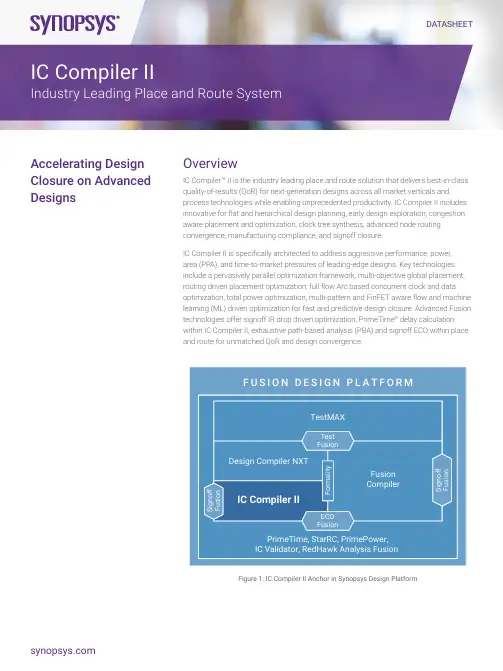
DATASHEETOverview IC Compiler™ II is the industry leading place and route solution that delivers best-in-class quality-of-results (QoR) for next-generation designs across all market verticals and process technologies while enabling unprecedented productivity. IC Compiler II includes innovative for flat and hierarchical design planning, early design exploration, congestion aware placement and optimization, clock tree synthesis, advanced node routing convergence, manufacturing compliance, and signoff closure.IC Compiler II is specifically architected to address aggressive performance, power, area (PPA), and time-to-market pressures of leading-edge designs. Key technologies include a pervasively parallel optimization framework, multi-objective global placement, routing driven placement optimization, full flow Arc based concurrent clock and data optimization, total power optimization, multi-pattern and FinFET aware flow and machine learning (ML) driven optimization for fast and predictive design closure. Advanced Fusion technologies offer signoff IR drop driven optimization, PrimeTime ® delay calculation within IC Compiler II, exhaustive path-based analysis (PBA) and signoff ECO within place and route for unmatched QoR and design convergence. F U S I O N D E S I G N P L A T F O R M PrimeTime, StarRC, PrimePower,IC Validator, RedHawk Analysis Fusion Fusion Compiler IC Compiler II Design Compiler NXT TestMAX F o r m a l i t y ECO Fusion S i g n o f f F u s i o n S i g n o f f F u s i o n Test Fusion Figure 1: IC Compiler II Anchor in Synopsys Design PlatformAccelerating DesignClosure on AdvancedDesignsIC Compiler II Industry Leading Place and Route SystemKey BenefitsProductivity• The highest capacity solution that supports 500M+ instances with a scalable and compact data model• A full suite of design planning features including transparent hierarchical optimization• Out-of-the-box simple reference methodology for easy setup• Multi-threaded and distributed computing for all major flow steps• Golden signoff accuracy with direct access to PrimeTime delay calculationPPA• Unified TNS driven optimization framework• Congestion, timing, and power-driven logic re-synthesis• IEEE 1801 UPF/multi-voltage support• Arc-based concurrent clock and data optimization• Global minima driven total power optimizationAdvanced Nodes• Multi-pattern and FinFET aware design flow• Next generation advanced 2D placement and legalization• Routing layer driven optimization, auto NDR, and via pillar optimization• Machine learning driven congestion prediction and DRC closure• Highest level of foundry support and certification for advanced process nodes• IC Validator in the loop signoff driven DRC validation and fixingAdvanced Fusion Technology• Physically aware logic re-synthesis• IR drop driven optimization during all major flow steps• PrimeTime delay calculation based routing optimization for golden accuracy• Integrated PrimeTime ECO flow during routing optimization for fastest turnaround timeEmpowering Design Across Diversified ApplicationsThe dizzying pace of innovation and highly diversified applications across the design spectrum is forcing a complete rethink of the place and route systems to design and implement differentiated designs in a highly competitive semiconductor market on schedule. Designers on emerging process nodes must meet aggressive PPA and productivity goals. It essentially means efficient and intelligent handling of 100s of millions of place-able instances, multiple levels of hierarchy, 1000s of hard macros, 100s of clocks, wide busses, and 10s of modes and corners power domains and complex design constraints and process technology mandates. Emphasis on Designer ProductivityIC Compiler II is architected from the ground up for speed and scalability. Its hierarchical data model consumes 2-3X less memory than conventional tools, boosting the limits of capacity to 500M placeable instances and beyond. Adaptive abstraction and on-the-fly data management minimize memory requirements and enable fast responsive data manipulation. Near-linear multi-core threading of key infrastructural components and core algorithms such as database access and timing analysis speed up optimization at all phases of design. Patented, lossless compact modeling and independent R and C extraction allow handling more modes and corners (MCMM scenarios) with minimal runtime impact.IC Compiler II has built-in Reference Methodology(RM) that ensures fast flow bring up. This RM Flow is Foundry Process/Design Type specific to ensure a robust starting point and seamless bring up. IC Compiler II has direct access to the Golden PrimeTime delay calculation engine to minimize ECO iterations.IC Compiler II’s new data model enables designers to perform fast exploration and floorplanning with complex layout requirements. IC Compiler II can create bus structures, handle designs with n-levels of physical hierarchy, and support Multiply Instantiated Blocks (MIBs) in addition to global route driven pin assignment/feedthrough flow, timing driven macro placement, MV area design planning.A design data mismatch inferencing engine analyzes the quality of inputs and drives construct creation on the fly, delivering design insights even with “incomplete” data early in the design cycle. Concurrent traversal of logical and physical data models enables hierarchical Data-Flow Analysis (DFA) and fast interactive analysis through multi-level design hierarchies and MIBs. Data flow and feedthrough paths highlighted in Figure 2 allow analysis and manipulation through n-levels of hierarchy to complete early design exploration and prototyping.Figure 2: Fast interactive analysis through multiple-levels of physical hierarchy and MIBPipeline-register-planning shown in Figure 3, provides guidance for optimal placement to meet the stringent timing requirementsof high-performance designs. Interactive route editor integrated which is advanced node aware shown in Figure 4, allows intricate editing and routing functions, including the creation of special signal routes, buses, etc.Figure 3: Pipeline register placement enables superior QoR for designs with complex busesAchieving Best Performance, Power, Area, and TATIC Compiler II features a new optimization framework built on global analytics. This Unified TNS Driven Optimization framework is shared with Design Compiler NXT synthesis to enable physically-aware synthesis, layer assignment, and route-based optimization for improved PPA and TAT. Multi-Corner Multi-Mode (MCMM) and Multi-Voltage (MV) aware, level-based analytical algorithms continuously optimize using parallel heuristic algorithms. Multi-factor costing functions deliver faster results on both broad and targeted design goals. Concurrent PPA driven logic remapping, rewiring, and legalization interleaved with placement minimizes congested logic, resulting in simple localized logic cones that maximize routability and QoR.IC Compiler II minimizes leakage with fast and efficient cell-by-cell power selection across HVT, SVT and LVT cells and varying channel lengths. Activity-driven power optimization uses VCD/ SAIF, net toggle rates, or probability functions to drive placement decisions and minimize pin capacitances. Multi-bit register banking optimizes clock tree structures, reduces area, and net length, while automatically managing clock, data, and scan chain connections.Advanced modeling of congestion across all layers highlighted in Figure 4 provides accurate feedback throughput the flow from design planning to post- route optimization.Figure 4: Intelligent and accurate analysis for congestion and powerIC Compiler II introduces a new Concurrent Clock and Data (CCD) analysis and optimization engine that is built-in to every flow step resulting in meeting both aggressive performance and minimizing total power footprint. ARC-based CCD optimization performs clock tree traversal across all modes/corners in path-based fashion to ensure optimal delay budgeting.Robust support for clock distribution enables virtually any clock style, including mesh, multi-source, or H-tree topologies. Advanced analysis and debugging features perform accurate clock QoR analysis and debugging as highlighted in Figure 5.Figure 5: Accurate clock QoR analysis and debugging (a & b) Abstracted clock graph and schematic.(c) Latency clock graph. (d) Colored clock tree in layout.IC Compiler II features many innovative technologies that make it the ideal choice for high-performance, energy-efficient Arm®processor core implementation, resulting in industry-best milliwatts/megahertz (mW/MHz) for mobile and other applications across the board. Synopsys and Arm work closely together to offer optimized implementation of popular Arm cores for IC Compiler II,with reference flows available for Arm Cortex®-A high-performance processors and Mali GPUs. In addition, Arm offers off-the-shelf Artisan® standard cell and memory models that have been optimally tuned and tested for fast deployment in an IC Compiler II environment. Continuous technology innovation and close collaboration makes IC Compiler II the leading choice for Arm-based high- performance design.Highest Level of Advanced Node Certification and SupportIC Compiler II provides advanced node design enablement across major foundries and technology nodes—including 16/14nm,12/10nm, 7/5nm, and sub-5nm geometries. Zroute digital router technology ensures early and full compliance with the latest design rules required for these advanced node technologies. Synopsys collaborates closely with all the leading foundries to ensure that IC Compiler II is the first to deliver support for early prototype design rules and support for the final production design rules. IC Compiler II design technologies maximize the benefits of new process technologies and offer optimal return on investment for cutting-edge silicon applications.IC Compiler II advanced node design support includes multi-pattern/FinFET aware placement and routing, Next-generation advanced 2D placement and legalization, routing layer driven optimization, auto NDR, and via pillar optimization. IC Validator in the loop provides signoff DRC feedback during Implementation.Foundry fill Track based fillFigure 6: IC Validator In-Design metal fill color aware metal fill, optimized for density and foundry requirementsMachine learning driven congestion prediction and DRC closure allow for fastest routing convergence with best PPA. Multiple sets of training data are used to extract key predictive elements that guide the pre-route flow.Advanced Fusion TechnologyThe Fusion Design Platform™ delivers unprecedented full-flow QoR and time-to-results (TTR) to accelerate the next wave of semiconductor industry innovation. The industry’s first AI-enhanced, cloud-ready Design Platform with Fusion Technology™ isbuilt from Synopsys’ market-leading, massively-parallel digital design tools, and augmented with innovative capabilities to tacklethe escalating challenges in cloud computing, automotive, mobile, and IoT market segments and accelerate the next wave of industry innovation.Fusion Technology redefines conventional EDA tool boundaries across synthesis, place-and-route, and signoff, sharing integrated engines across the industry’s premier digital design products. It enables designers to accelerate the delivery of their next-generation designs with the industry-best QoR and the TTR.©2019 Synopsys, Inc. All rights reserved. Synopsys is a trademark of Synopsys, Inc. in the United States and other countries. A list of Synopsys trademarks isavailable at /copyright.html . All other names mentioned herein are trademarks or registered trademarks of their respective owners.。
DescriptionThe vb5Portable Data Collector instrument is a portablesingle channel vibration data collector.It is ergonomicallydesigned and lightweight for all day comfort.You can use thisdevice for on-route as well as off-route data collection.The vb5Portable Data Collector provides recordings with upto6,400lines of resolution and up to40kHz F max.Ourpatented adaptive settling algorithm and6Pack recordingsystem offer quick,one-step data recording.The data collector has plenty of storage and long battery life,and is backed by a five year warranty.The vb5Portable Data Collector is one of Bently Nevadahardware monitoring assets that work with System1software.The vb5Portable Data Collector offers the followingfeatures:l Single channel recordingsl6,400lines FFT resolutionl Supports40kHz F maxl1GB memoryl≥95dB dynamic rangel Spectrum and waveform recordingsl Demodulation for early detection of rotating machineryproblems such as bearing faultsl Unique6Pack recording systeml Cable test model Option to add flex features such as balancing andRemote Commsl Upgradable Proflash system and free firmware updatesfor5yearsl Five-year warranty on the instrumenthardware vb5Portable Data CollectorDatasheetBently Nevada Machinery Condition Monitoring111M6572Rev.HSpecifications SensorsSensor Input One channel CompatibleSensor TypesAccelerometerAC Coupled Range 16V peak-peak Allows for±8 V sensor output swing(±80 g)Connectors1x BNC(CH1)Safety feature: Break-freeinline connector Analog toDigitalConversion24-bit ADCSensor Excitation Current 0mA or2.2mA (configurable),24V maximum2.2mA required power for IEPE/ICP type accelerometerSensor Detection Warns if short circuit or not connectedTachometer Sensor(Optional) Sensor Type Laser sensor with reflectivetape Sensor triggers onbeam reflectionLaser Sensor Range 10cm to2m nominal Rangedepends on size of reflectivetapeTachometer InputSupportedSensor TypesLaser Tach,Contact,TTLPulse Instrument hasoptically isolated inputPower Supplyto Sensor5V,50mATTL PulseRating 3.5V(4mA)min28V(5mA)max Off-state0.8VSpeed Range10RPM to300,000RPM(0.2Hzto5kHz)Pulse width at least0.1msAccuracy±0.1%Parameter IndicationMaximumLevels(peak)>1000g(10,000m/s2)>1000in/sec(25,000mm/s)>20in(500mm)Effective limit is sensorsensitivity and outputvoltageDynamicSignal Range>95dBtypical at400line resolutionHarmonicDistortionLess than-70dB typicalOther distortions and noiseare lowerUnits g or m/s2or adB in/s ormm/s or vdB mil or mm orµm0-peak,peak-peak or RMSAuto-scale by1000x whenrequiredUS and SI options for ampsand voltsMagnitude andCursorsOverall RMS value WaveformTrue pk-pk Dual cursorsHarmonicsDigital readouts on chartBase Accuracy±1%of readingsapproximately0.1dB%of readingHigh Frequency Attenuation ≤0.1dB100Hz to10kHz≤3dB >10kHz to40kHz Attenuation tolerances are in addition to base accuracy.AC Coupling Attenuation ≤0.1dB10Hz to<100Hz≤3dB1 Hz to<10HzAttenuation Due to Integration ≤0.1dB1Hz to<100Hz≤1.5dB 0.2Hz to<1HzValues apply to single integration.(Acceleration to velocity)Double the values for double integration(Acceleration to displacement)Spectrum DisplayF max Ranges25,50,100,125,150,200,300,400,500,600,800,1000,1200,1600,2000,2500,3000,4000,5000,6000,8000,10,000,15,000,20,000,30,000,40,000Hz Or equivalent CPM valuesOr orders-based from1X to999XF min Possible Range 0to F max Instrument zeroes all spectral lines below F minResolution400,800,1600,3200,6400linesFrequency Scale Hz,CPM,Orders Linear scale with zoomingAmplitude Scale Acceleration,velocity, displacement Linear or log scales,auto or manual scalingWindow Shapes Hanning RectangularOverlap(0,12.5,25,37.5,50,62.5,75,87.5)%Depends on F max andnumber of linesNumber ofAverages1,2,4,8,16,32,64,128Increases sampling timeproportionallyAveragingTypesLinear,exponential,peakholdDemodulationBandwidths23bandwidth options From125Hz to1250Hz Up to16kHzto20kHz6Pack Up to40kHz&3200lines(1channel)Spectrum andwaveform for low-frequency,high-frequency anddemodulationWaveform DisplayNumber ofSamples1024,2048,4096,8192,16,384Time Scale10ms to256seconds ororders based from1to999revsLogging and AnalysisOutputFormatsInstrument screen,transferto System1,XMLData Storage Dual1GB non-volatile flashmemories Database mirrorcopy on second flashmemoryData StorageStructureFolders/machines/points/locations/routesNo limits are applied50character namesMax Folder Size10,000measurementlocationsDisplay and Communication Display Graphic Grayscale LCD LEDBacklightResolution and Size 480x320(HVGA),5.5”(140 mm)Readable in direct sunlightSupported Languages English,Chinese,French, German,Japanese, Portuguese,Russian and SpanishCommunication with PC USB or EthernetUse PROFLASH to upgrade instrument firmwareUSB Host Port USB2.0,supplying5V,250mA Save folders to USBflash driveBattery and ChargerBattery Type Custom Lithium Ion pack,7.4V,5 AhOperating Time 10hours Backlight on—60 second timeoutCharger Type Internal charging,automatic control External power pack12V DC,3A outputCharge Rate 3A nominal3hours for complete chargeMechanicalSize9.9"W x5.8"L x2.4"H(252x148x60mm)Weight 2.7lb(1.2kg)Includingbattery and strap Environmental LimitsOperatingTemperature14°F to122°F(-10to50°C)StorageTemperatureand Humidity-4°F to140°F(-20to60°C),95%RHUp to95F(35C),85%RH ifstorage exceeds1month Ruggedness IP65sealed4’(1.2m)droponto concrete Procedure:26drops following MIL-STD-810F-516.5-IVCompliance and CertificationsFCCThis device complies with part15of theFCC Rules.Operation is subject to thefollowing two conditions:l This device may not cause harmfulinterference.l This device must accept anyinterference received,includinginterference that may causeundesired operation.EMCEN61326-1:2012EN61326-2-3:2012EMC Directive2014/30/EU Electrical SafetyEN62133:2002LV Directive2014/35/EURoHSRoHS Directive2011/65/EU Hazardous Area ApprovalsFor the detailed listing of country andproduct specific approvals,refer tothe Approvals Quick Reference Guide(108M1756)available from .CSA/NRTL/C(Approval Option01)Class I,Division2,Groups A,B,C,DOrdering InformationFor the detailed listing of country andproduct specific approvals,refer tothe Approvals Quick Reference Guide(108M1756)available from . VB5-AAA:Agency Approval01CSABasic KitWe offer the vb5Portable Data Collector instrument in a basic kit with the option to purchase the System1software and license separately.*Kit items with multiple part numberslisted have limited regional availabilitydue to certification requirements.Metrology certification can be requested when an order is placed,however this service is charged.Standard test data can be requested for free,but is not evidence of calibration.To request a periodic metrology calibration,contact Bently Nevada Tech Suppport.Additional Accessories SoftwareHardwareCopyright2021Baker Hughes Company.All rights reserved.Bently Nevada,Keyphasor,SCOUT,System1and Orbit Logo are registered trademarks of Bently Nevada,a Baker Hughes Business,in the United States and other countries.The Baker Hughes logo is a trademark of Baker Hughes Company.All other product and company names are trademarks of their respective e of the trademarks does not imply any affiliation with or endorsement by the respective holders.Baker Hughes provides this information on an“as is”basis for general information purposes.Baker Hughes does not make any representation as to the accuracy or completeness of the information and makes no warranties of any kind,specific,implied or oral,to the fullest extent permissible by law,including those of merchantability and fitness for a particular purpose or use.Baker Hughes hereby disclaims any and all liability for any direct,indirect, consequential or special damages,claims for lost profits,or third party claims arising from the use of the information,whether a claim is asserted in contract,tort,or otherwise.Baker Hughes reserves the right to make changes in specifications and features shown herein,or discontinue the product described at any time without notice or obligation.Contact your Baker Hughes representative for the most current information.The information contained in this document is the property of Baker Hughes and its affiliates;and is subject to change without prior notice.It is being supplied as a service to our customers and may not be altered or its content repackaged without the express written consent of Baker Hughes.This product or associated products may be covered by one or more patents.See /legal.1631Bently Parkway South,Minden,Nevada USA89423Phone:1.775.782.3611(US)or /support。

CCNA考试题库中英文翻译版及答案.A. The area of overlap of the two cells represents a basic service set (BSS).A. 两个 cells的overlap的区域描述了一个basic service setB. The network diagram represents an extended service set (ESS).B. 网络描述了一个extended service setC. Access points in each cell must be configured to use channel 1.C. 再每个CELL中的AP必须被配置成使用channel 1D. The area of overlap must be less than 10% of the area to ensure connectivity.D. 为了确保连通性,重叠区域必须小于10%E. The two APs should be configured to operate on different channels.E. 两个访问点应该被配置成工作在不同的频道Answer: BE6. The command frame-relay map ip 10.121.16.8 102 broadcast was entered on the router.Which ofthe following statements is true concerning this command?6.路由器上输入命令frame-relay map ip 10.121.16.8 102 broadcast,以下选项正确的是?A. This command should be executed from the global configuration mode.A.该命令应该在全局配置模式下被执行B. The IP address 10.121.16.8 is the local router port used to forward data.B.IP地址10.121.16.8是本地路由器用来转发数据的接口C. 102 is the remote DLCI that will receive the information.C.102是远端的DLCI它将接受信息。
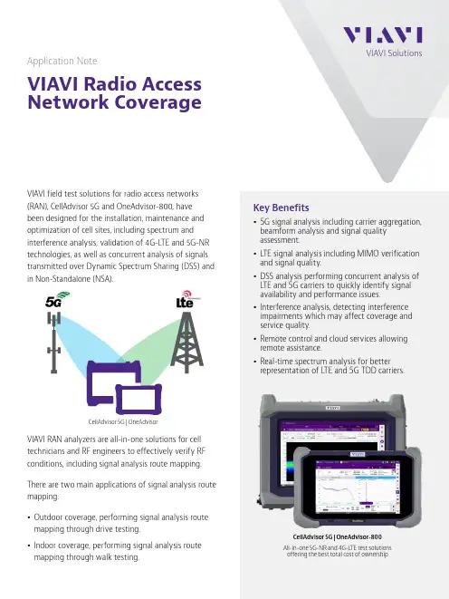
Application NoteVIAVI Radio Access Network CoverageVIAVI field test solutions for radio access networks(RAN), CellAdvisor 5G and OneAdvisor-800, have been designed for the installation, maintenance and optimization of cell sites, including spectrum and interference analysis, validation of 4G-L TE and 5G-NR technologies, as well as concurrent analysis of signals transmitted over Dynamic Spectrum Sharing (DSS) and in Non-Standalone (NSA).VIAVI RAN analyzers are all-in-one solutions for cell technicians and RF engineers to effectively verify RF conditions, including signal analysis route mapping.There are two main applications of signal analysis route mapping:y Outdoor coverage, performing signal analysis route mapping through drive testing.y Indoor coverage, performing signal analysis route mapping through walk testing.Key Benefitsy5G signal analysis including carrier aggregation, beamform analysis and signal quality assessment.y L TE signal analysis including MIMO verification and signal quality.y DSS analysis performing concurrent analysis of L TE and 5G carriers to quickly identify signal availability and performance issues.y Interference analysis, detecting interference impairments which may affect coverage and service quality.y Remote control and cloud services allowing remote assistance.y Real-time spectrum analysis for better representation of L TE and 5G TDD carriers.CellAdvisor 5G | OneAdvisorCellAdvisor 5G | OneAdvisor-800All-in-one 5G-NR and 4G-L TE test solutionsoffering the best total cost of ownershipRadio Access Outdoor CoverageOutdoor coverage can be affected by shadowing in the case of mm-wave signals that experience high penetration loss through materials such as concrete, steel or reflective glass; as well as the effects from interfering signals that collide with the radio’s transmission or reception bands, which in cases despite of acceptable signal levels the throughput is limited or might even cause call drops.VIAVI RAN analyzers are equipped with route map test functions that performs coverage testing in real-time, by plotting signal strength, with different color scheme based on the received power level, in a geographical map obtaining location from GPS. The resulting route map shows coverage levels and dead-zones or areas with no coverage which might cause service impairments such as call drops.Coverage test data can be saved as a mapping test result allowing post-analyze with the RAN analyzer displaying signal analysis parameters for each data point including originating physical cell identification or PCI, as well as beamforming profile including beam index and beam power level. In addition, coverage test data can also be saved as comma separated files for post-processing analysis.Radio Access Indoor CoverageIndoor coverage can be affected by many factors, including reflections and attenuation caused by building materials including concrete walls, steel, and reflective windows, as well as for potential interfering signals that collide with signals of small cells or customer premise equipment.Therefore, it is essential in the deployment of indoor networks to verify the spectrum is clear, verifying no other signals are present, avoiding service quality impairments; and subsequently the network is not causing interference to other networks.VIAVI RAN analyzers can perform indoor coverage mapping in two different modes to obtain location and overcoming the lack of GPS information availability for indoor networks:y Manual geo-location, assisted by user intervention selecting the physical location. y Automatic geo-location, assisted by NEON Tracker and NEON Signal Mapper.RAN analyzer – 5G Signal Analysis Route MappingRAN analyzer – Signal Analysis Route Map 5G-NRIndoor Coverage with Manual Geo-LocationIndoor coverage mapping with manual geo-location is achieved by a simple test process:1. Indoor map creation, with VIAVI JDMapCreator software that convertspicture files of indoor layouts or floor plans into a file format readable by the RAN analyzer.2. Perform signal analysis route mapping with the RAN analyzer andsetting map configuration plot point by time or position.3.Manually select the location on the map displayed in the RAN analyzerCellAdvisor 5G | OneAdvisor-800JDMapCreatorRAN analyzer – Signal Analysis Route Map 5G-NR Beam ProfileIndoor Coverage with Automatic Geo-LocationIndoor coverage mapping with automatic geo-location is assisted by NEON tracker to obtain a geographical reference position, and NEON Signal Mapper that correlates this position with signal analysis measurements from VIAVI’s RAN analyzer, resulting in an accurate indoor network coverage map. The test process is as follows:1. VIAVI RAN analyzer: setup the corresponding RF antennaand configure the signal analysis test function to test the signal of interest and establish Wi-Fi connectivity with the device running NEON signal mapper.2. Personnel tracker, initialize the tracker and establishBluetooth connectivity with the device running NEON Signal Mapper3. NEON Signal Mapper, launch the application and configureconnectivity with the tracker and RAN analyzer; then select the type of signal coverage test to be performed, LTE or 5G.NEON Signal MapperNEON Signal Mapper – Indoor & Outdoor 5G CoverageNEON Command - 4G & 5G Signal ProfileCarrier Profile5G carrier profile verification is needed to validate over-the-air characteristics including spectrum clearance.1. Carrier Channel: compliant with3GPP ARFCN.2. Carrier Center Frequency: verifythe channel frequency corresponds to the center frequency of the transmitted signal.3. Carrier bandwidth: verify the signalbandwidth correspond to the defined carrier bandwidth. 4. Carrier Power: verify thetransmitted signal has proper signal strength (e.g. level ≥ -90dBm).5. Carrier Interference: verify thesignal transmitted is not affected by any interfering signal.RAN Troubleshooting Best PracticesSolving Network Coverage IssuesVIAVI RAN analyzers solves network coverage and improves user experience through the following cell site deployment best practices:RAN analyzer – Carrier Profile5G beam profile verification is needed to validate over-the-air characteristics and radio configuration of the beam numerology.1. Beam Bandwidth: validate theradio’s 5G beam numerology (µ) of sub-carrier spacing (∆f): 15KHz to 240KHz.2. Beam Raster: verify the 5G beam(SSB) frequency offset relative to the 5G channel.3. Beam Power: verify the 5G beam(SSB) transmitted power level (e.g. level ≥ -90dBm).Carrier Aggregation5G carrier aggregation verification is needed to validate power level, linearity and quality of the 5G radio.1. Channel Power: verify signalstrength of the transmitted carrier.2. Carrier Linearity: verify the carrierstransmitted by the radio have the same power level.3. Beam Quality: verify 5G beamquality (constellation) performance.4. 5G Radio ID: verify the radioID (PCI).RAN analyzer – Beam Profile VerificationRAN analyzer – Carrier Aggregation5G beamforming verification is needed to validate beams transmitted by the radio, beam power, and quality.1. Beams Transmitted: verify theindividual beams transmitted.2. Beam Power: verify the power levelof the individual beams.3. Beam Quality: verify 5G beamquality performance (constellationand error vector magnitude).Signal Coverage5G coverage verification is needed to validate proper power levels in different location suitable for 5G service.1. 5G coverage: Assess signalstrength by geo-location.2. Beam availability: verify theavailability of multiple beamsby geo-location.5G Coverage data done in real-timeand available for post-processingRAN analyzer - BeamformingRAN analyzer – Signal CoverageSummaryVIAVI RAN analyzers, CellAdvisor 5G and OneAdvisor, are the ideal all-in-one test solutions for radio access networks, their portability allows conducting field tests in the front-haul, and over-the-air, including spectrum and interference analysis, as well as L TE and 5G signalanalysis and coverage testing for indoors and outdoors.© 2021 VIAVI Solutions Inc.Product specifications and descriptions in this document are subject to change without notice.rancoverage-an-nsd-nse-ae 30192982 900 0221Contact Us +1 844 GO VIAVI (+1 844 468 4284)To reach the VIAVI office nearest you, visit /contactOrdering InformationCellAdvisor 5GOneAdvisorNEON Tracker and Signal Mapper。

Built on the proven track record of the classic vbSeries® portable vibration analyzers and balancers, the all-new vbSeries data collectors, analyzers, and balancers have been re-engineered from the ground up to offer leading-edge reliability, accuracy and usability.• Improved ergonomics for walkaround data collection• Large, high resolution (HVGA) backlit LCD • True left- and right-handed operation • Multi-channel on route recordings (collectors and analyzers only)• 1 GB memory – virtually unlimited spectra and waveform storage • 10 hour battery life• Lightweight, rugged IP65 rated cases•DC coupled sensor support • 12 800 lines of resolution (max)• 40 kHz Fmax• Single, Dual or Four-channel recordings depending on model • Triax. compatibility (vb6™ and vb8™ instruments only)• CSA Class I, Division 2 Hazardous Locations certification• USB host port for data transfer toexternal USB memoryData CollectorsData AnalyzersBalancersLean vb5vb7 vbBalancer Deluxevb6vb8vbBalancer+Choose the model most suitable for your needs. Our tiered instrument range allows you to select an appropriate set of features at a cost effective price. Choose a model tailored to your requirements with the added peace of mind provided by our rock solid 5 year warranty.EASY AND EFFICIENT TWOCHANNEL CAPABILITYThe vb7™ analyzer offers the power and convenience of dual-channel measurement and dual-plane balancing. Its balancing functions enable the quick diagnosis and correction of dynamic unbalance, the most commonform of unbalance. The vb7 instrument’s combinationof accuracy, intuitive operation, ease of use and outstanding storage capacity ensures the vb7 analyzer delivers a premium return on investment. The vb7 instrument includes the powerful Ascent® software in the purchase price.Ascent Level 2 enables you to program the instrumentwith thousands of separate machine definitionscovering a number of route choices. A library of over 300 customizable parameter sets is also available enabling a vast array of measurement options.Ascent Level 2 software:• Route enabled - build routes in Ascent software andsend to the instrument• CBDb - Commtest Bearing Database with over30 000 bearings• Orbit and Bode plots• Waveform analysis tools - perfect for the power user • User-designable SQL/HTML reports - unlimited reporting flexibility• Statistical alarm creation and adjustmentEnhanced instrument functionality• Improved ergonomics for walk around data collection • 2 channel simultaneous recordings• True left- and right-handed operation• Wide measurement range:1000 g, 25 000 mm/s, 2500mm• 2 plane balancing• ≥ 95 dB dynamic range• 6400 line FFT resolution• 40 kHz Fmax• 1 GB memory – virtually unlimited spectra andwaveform storage• Laser speed sensor for automatic capture of machine running speed• Keyphasor® tach mode• 5 year warranty on the instrument hardwareHIGH RESOLUTION, FOUR CHANNELMEASUREMENTS FOR PROACTIVE MAINTENANCE PROFESSIONALSThe vb6™ data collector is a four channel, route-enabled product that provides everything needed for advanced, high resolution data collection.This instrument includes a wide range of recordingand measurement types at up to 12 800 lines of resolution. The vb6 includes the powerful Ascent®software in the purchase price.Ascent Level 1 enables you to program the instrument with thousands of separate machine definitions covering a number of route choices.A library of over 300 customizable parametersets is also available enabling a vast array of measurement options.Ascent Level 1 software:• Route enabled - build routes in Ascent softwareand send to the instrument• CBDb - Commtest Bearing Database with over30 000 bearingsEnhanced instrument functionality• 4 channel simultaneous recordings• 12 800 line FFT resolution• 40 kHz Fmax• Laser speed sensor for automatic capture of machine running speed• 1 GB memory – virtually unlimited spectra storage• ≥ 95 dB dynamic range• Large, high resolution (HVGA) backlit LCD• Voltage output sensor support• User-defined recordings for Temperature, Pressure, Mass Flow, Force and Power• 5 year warranty on the instrument hardwareTHE ECONOMICAL SOLUTION FOR THEPROACTIVE MAINTENANCE PROFESSIONAL The vb5™ data collector is a single channel, route-enabled product that provides everything needed for cost effective data collection and analysis. Using this instrument maintenance professionals are ableto easily take recordings with up to 6400 lines ofresolution and greater than 95 dB of dynamic range, and all at a low price that represents exceptional value for money. The vb5 instrument includes the powerful Ascent® software in the purchase price. Ascent Level 1 enables you to program the instrument with thousands of separate machinedefinitions covering a number of route choices.A library of over 300 customizable parameter sets is also available enabling a vast array of measurement options.Ascent Level 1 software:• Route enabled - build routes in Ascent software and send to the instrument• CBDb - Commtest Bearing Database with over 30 000 bearingsEnhanced instrument functionality• 1 channel recordings• 6400 line FFT resolution• 40 kHz Fmax• 1 GB memory – virtually unlimited spectra storage • ≥ 95 dB dynamic range• Spectrum and Waveform recordings• Large, high resolution (HVGA) backlit LCD• 5 year warranty on the instrument hardwareFOUR CHANNEL UNBALANCECORRECTION PACKAGELightweight and extremely portable, the vbBalancer+™ 4 channel and vbBalancer™ 2 channel instruments are easily carried on site to any problematic machine. Their 10 hour battery lifeand 1 GB of internal memory ensure progress isuninterrupted, practically eliminating the need to pause in order to connect to a PC or power supply. The vbBalancer instruments also carry Commtest’s legendary 5 year warranty and free lifetime support as standard.Unbalance causes high levels of mechanical stressand vibration that are transferred directly to the bearings resulting in a proportional reduction in normal bearing life. With a few basic parameters the vbBalancer instruments calculate acceptable unbalance levels to ensure machinery operateswithin international ISO 1940 guidelines.SetupvbBalancer instrument setup is minimal, quick and easy. Only a few calibration runs are required, with or without removing your trial weight.MemoryThe vbBalancer instrument stores your previous balance run data. No need to waste valuable time performing calibration runs on repetitive or routinebalance jobs.BalanceUnbalance is computed quickly and the large backlit LCD display and user-friendly graphical interface indicate the angular position for weight correction.The vbBalancer+ instrument allows full 4-sensor monitoring of both horizontal and vertical axes on each bearing. This ability provides confidence that a balance on any one axis has not worsened vibrationson the other.Commtest, Inc. 6700 Baum DriveSuite 12Knoxville, Tennessee 37919 Telephone 865 588-2946 Facsimile 865 588-2949 USA Toll Free 877 582-2946 *********************CommtestInstruments LtdLevel 2, 22 Moorhouse AvePO Box 9297ChristchurchNew ZealandTelephone +64 3 374 2337Facsimile +64 3 374 2339******************CommtestInstruments LtdPO Box 502689Dubai Internet CityDubai, United Arab Emirates***********************®E s t a b l i s h e d1981 Advanced Test Equipment Rentals Advanced Test Equipment Rentals 800-404-ATEC (2832)。
Spectrum WiFi 6 RouterUser GuideAdvanced In-Home WiFiAdvanced In-Home WiFi is included on your Spectrum WiFi 6 router delivering internet, network security and personalization, conveniently managed with the My Spectrum App. Your router will have a QR code on the back label to indicate support of this service.With Advanced In-Home WiFi, you can:• Personalize your WiFi network name (SSID) and password• View and manage devices connected to your WiFi network• Pause or resume WiFi access for a device, or group of devices, connected to your WiFi network• Get port forwarding support for improved gaming performance• Have peace of mind with a secure WiFi network• Use both wireless and Ethernet connectivityGet Started with My Spectrum AppTo get started, download My Spectrum App on Google Play or the App Store. Another method to download My Spectrum App is to scan the QR code on the router label with your smartphone camera, or go to /getappPersonalize Your WiFi Network Name and PasswordTo secure your home network, we recommend creating a unique network name and an alphanumeric password. You can do this in the My Spectrum App or at Troubleshooting Your Internet ServiceIf you’re experiencing slow speeds or if you lose connection to your WiFi network, check the following: Distance from the WiFi router: The farther away you are, the weaker the signal will be. Try moving closer. Router location: Your router should be placed in a central location for best coverage.Where to place your router for the best coverage• Do place in a central location• Do place on a raised surface• Do place in an open space• Don’t place in a media center or closet• Don’t place near devices like cordless phones that emit wireless radio signals• Don’t place behind a TVSpectrum WiFi 6 Router with Advanced In-Home WiFiThe router’s front panel features the status LED (light) which indicates the process the router is going through while establishing your home network. LED status light colors:Status LightsOffDevice is offBlue flashingDevice is booting upBlue pulsingConnecting to the internetBlue solidConnected to the internetRed pulsingConnectivity issue (no internet connection)Red and Blue alternatingUpdating firmware (device will automatically restart)Red and White alternatingDevice is overheatingThe router’s side panel features:Reboot - Press and hold for 4 - 14 seconds to reboot router.Your personalized configurations will not be removed. Factory reset -Press and hold for more than 15 seconds toreset router to factory default settings. Warning: Your personalized configurations will be removed.Ethernet (LAN) port -Connect network cables for local area network connection e.g. PC, game console, printer.Internet (WAN) port - Connect network cable to themodem for wide area network connection.Power plug - Connect provided power supply to homeoutlet power source.The router’s label callouts:MAC Address - Physical address of the deviceQR Code - Used to scan to download the My Spectrum AppNetwork Name and Password - Used to connect to WiFi networkSerial Number - Serial number of the deviceNeed Help or Have Questions?We’re here for you. To learn more about your services or get support,visit /support or call us at(855) 632-7020.Spectrum WiFi 6 Router Technical Specs。
With VibePro 8IPAD VIBRATION ANALYSIS WITH VIBEPRO 8 // 2NEW IN VIBEPRO 8• TWF collection and on-screen analysis •FFT in Acceleration and integrated FFT in Velocity and Displacement (available on iPad and VibePro Online)• TWF and Spectrum in same view • High-frequency impact demodulation (available on iPad and VibePro Online)• Selection of sample rate (Fmax)and number of samples (lines of resolution)• Additional windowing options: hemming, hamming and blackman• Circular TWF plots for gearbox analysis • Waterfall plot for selected measurements •Vibration trending in acceleration/Velocity for RMS, Peak & Crest Factor Values• Editing Functions in Route • Allows: deleting, duplication, and renaming route data • Machine Point Library• Change Sensors Quickly with Calibration Presets•TWF Capture and AnalysisFEATURES• Real Time Spectrum Analysis• Single measurement reports with easy email sharing• Recorded readings for post processing • Routes have never been easier with VibePro.• Import and export routes via GTI Cloud, Files app, email and other options • Automatic and manual markers on the spectrum• Set RPM and bearing makers with multiples • Full FFT Signature graph from 0 to 20khz or 0 to 1.2 million CPM • Spectrum Frequency Resolution from 0.17Hz to 10.77Hz•Selectable Fmax of 22,050Hz, 11,025Hz, 5,512Hz and 2,756Hz•Selectable number of samples of 4,096, 8,192, 16,384 and 32,768VIBEPROIs a powerful machine vibration analyzer app for iPad/iOS. Coupled with GTI sensor equipment, it can be an invaluable tool for measuringvibration and health of a wide variety of machine parts including motors, bearings, spindles, shaft imbalance, gears, belt wear and more. The app can be used for single readings or full vibration analysis routes, documenting trends along the way. Route data can be processed directly in VibePro, GTI’s web app or other platforms available for Windows and MacOS.The contents of this publication are the copyright of the publisher and may not be reproduced (even extracts) unless prior writtenpermission is granted. Every care has been taken to ensure the accuracy of the information contained in this publication but no liability canbe accepted for any loss or damage whether direct, indirect or consequential arising out of the use of the information contained herein.888.473.9675 // 33 Zachary Road // Manchester, NH GTI HEATMAP:A custom vibration degradationalgorithm developed by GTI brings a new visualization tool to the health of a plant’s assets.The larger the box the faster that asset is degrading. GTI HeatMap for the first time provides an accurate look at a plant’s health. Green assets that are rapidly failing will show up well before an emergency repair is needed. GTI HeatMap can also be a helpful tool to ensure thresholds are being properly setup.FULL HIERARCHY VIEW WITHWATERFALL, TREND CHARTS, ANDSPECTRUM ANALYSIS WITH REPORTING:View the same route hierarchy that is used with VibePro for iPad. Full reporting is available for any reading captured with VibePro. Trend charts or waterfall view to see data trends. TWF analysis is also available.VIBEPULSE:A custom vibration signature recognition algorithmdeveloped by GTI brings a new fault detection technology not offered elsewhere. The fault detection algorithm will provide a good starting point for your technicians to fix the asset and return it back to normal vibration levels.VIBEPRO ONLINE: POST PROCESSINGSINGLE-MEASUREMENTSROUTE MEASUREMENTSVIBEPRO 8 IPAD VIBRATION ANALYSISFull Spectrum Email and Printer Friendly ReportsCreate, Edit and Manage RoutesCustom Options for MeasurementCapture Route Vibration DataView Plant Status Review Past Readings View Trending DataView and Create Maintenance。
©2019 Mellanox Technologies. All rights reserved.†For illustration only. Actual products may vary.Mellanox SN2700 provides the most predictable, highest density 100GbE switching platform for the growing demands of today’s data centers.The SN2700 switch is an ONIE (Open Network Install Environment) based platform that supports amultitude of operating systems, as well as utilizing the advantages of Open Ethernet and the capabilities of the Mellanox Spectrum ® ASIC.The SN2700 has three modes of operation:–Preinstalled with Mellanox Onyx™ (successor to MLNX-OS Ethernet), a home-grown operating system utilizing common networking user experiences and industry standard CLI.–Preinstalled with Cumulus ® Linux, a revolutionary operating system taking the Linux user experience from servers to switches and providing a rich routing functionality for large scale applications. –Provided with a bare ONIE image ready to be installed with the aforementioned or other ONIE-based operating systems.The SN2700 switch is an ideal spine and top-of-rack (ToR) solution, allowing maximum flexibility, with port speeds spanning from 10Gb/s to 100Gb/s per port and port density that enables full rack connectivity to any server at any speed. The uplink ports allow a variety of blocking ratios that suit any application requirement.Powered by the Spectrum ASIC and packed with 32 ports running at 100GbE, the SN2700 carries a whopping throughput of 6.4Tb/s with a landmark 4.76Bpps processing capacity in a compact 1RU form factor.Keeping with the Mellanox tradition of setting performance record switch systems, the SN2700introduces the world’s lowest latency for a 100GbE switching and routing element, and does so while having the lowest power consumption in the market. With the SN2700, the use of 25, 40, 50 and 100GbE in large scale is enabled without changing power infrastructure facilities.The SN2700 is part of Mellanox’s complete end-to-end solution which provides 10GbE through 100GbE interconnectivity within the data center. Other devices in this solution include the ConnectX ® family of network interface cards, and LinkX ® copper or fiber cabling. This end-to-end solution is topped with Mellanox NEO® a management application that relieves some of the major obstacles when deploying a network. NEO enables a fully certified and interoperable design, speeds up time to service and eventually speeds up ROI.Spectrum-based 32-port 100GbE Open Ethernet PlatformSN2700 Open Ethernet SwitchPRODUCT BRIEFSWITCH SYSTEM †©2019 Mellanox Technologies. All rights reserved.The SN2700 introduces superior hardware capabilities including dynamic flexible shared buffers and predictable wire speed performance with no packet loss for any packet size.While Spectrum provides the thrust and acceleration that powers the SN2700, the system gets yet another angle of capabilities while running with a powerful x86-based processor, which allows this system to not only be the highest performing switch fabric element, but also gives the ability to incorporate a Linux running server into thesame device. This opens up multiple application aspects of utilizing the high CPU processing power and the best switching fabric to create a powerful machine with unique appliance capabilities that can improve numerous network implementation paradigms.While the SN2700 Ethernet switch series is aimed at the100/50/25GbE market, Mellanox offers the SN2700B series for the 40/10GbE market. SN2700B switches are priced comfortably for the 40/10GbE market and provide the superior feature set of Spectrum.FEATURESPower Specifications–Typical Power with passive cables (ATIS): 150W –Input range:100-127 VAC, 200-240VAC –Frequency: 50-60Hz, single phase AC, 4.5A, 2.9APhysical Characteristics–Dimensions:1.72’’ (43.8mm) H x 16.84’’ (427.83mm) W x 27’’ (686mm) D–Weight: 11.1kg (24.5lb)Supported Modules and Cables* –QSFP28, SFP28 (with QSA) shortand long range optics –QSFP28 to QSFP28 DAC cable –QSFP breakout cables 100GbE to4x25GbE and 40GbE to 4x10GbE DAC, optical–QSFP breakout cables 100GbE to2x50GbE DAC, optical –QSFP AOC –1000BASE-T and 1000BASE-SX/LX/ZX modules SPECIFICATIONS* Systems limited to 40GbE will support modules and cables accordingly* This section describes hardware features and capabilities. Please refer to the driver and firmware release notes for feature availability.Layer 2 Feature Set–Multi Chassis LAG (MLAG) –IGMP V2/V3, Snooping, Querier –VLAN 802.1Q (4K) –Q-In-Q–802.1W Rapid Spanning Tree –BPDU Filter, Root Guard –Loop Guard, BPDU Guard –802.1Q Multiple STP–PVRST+ (Rapid Per VLAN STP+)–802.3ad Link Aggregation (LAG) & LACP –32 Ports/Channel - 64 Groups Per System –Port Isolation –LLDP–Store & Forward / Cut-through mode of work –HLL–10/25/40/50/56/100GbE –Jumbo Frames (9216 BYTES)Layer 3 Feature Set–64 VRFs–IPv4 & IPv6 Routing inc Route maps: –BGP4, OSPFv2–PIM-SM & PIM-SSM (inc PIM-SM over MLAG)–BFD (BGP , OSPF, static routes) –VRRP–DHCPv4/v6 Relay–Router Port, int Vlan, NULL Interface for Routing–ECMP , 64-way–IGMPv2/v3 Snooping QuerierSynchronization–PTP IEEE-1588 (SMPTE profile) –NTPQuality of Service–802.3X Flow Control –WRED, Fast ECN & PFC–802.1Qbb Priority Flow Control –802.1Qaz ETS–DCBX – App TLV support–Advanced QoS- qualification, Rewrite, Policers – 802.1AB–Shared buffer managementManagement & Automation–ZTP–Ansible, SALT Stack, Puppet –FTP \ TFTP \ SCP–AAA , RADIUS \ TACACS+ \ LDAP –JSON & CLI , Enhanced Web UI –SNMP v1,2,3–In-band Management –DHCP , SSHv2, Telnet –SYSLOG–10/100/1000 ETH RJ45 MNG ports –USB Console port for Management –Dual SW image –Events history –ONIENetwork Virtualization–VXLAN EVPN – L2 stretch use case –VXLAN Hardware VTEP – L2 GW–Integration with VMware NSX & OpenStack, etcSoftware Defined Network (SDN)–OpenFlow 1.3: • Hybrid• Supported controllers: ODL, ONOS, FloodLight, RYU Docker Container–Full SDK access through the container –Persistent container & shared storageMonitoring & Telemetry–What Just Happened (WJH) –sFlow–Real time queue depth histograms & thresholds–Port mirroring (SPAN & RSPAN) –Enhanced Link & Phy Monitoring –BER degradation monitor –Enhanced health mechanism –3rd party integration (Splunk, etc.)Security–USA Department of Defense certification – UC APL–System secure mode – FIPS 140-2 compliance –Storm Control–Access Control Lists (ACLs L2-L4 & user defined)–802.1X - Port Based Network Access Control –SSH server strict mode – NIST 800-181A –CoPP (IP filter) –Port isolation© Copyright 2019. Mellanox Technologies. All rights reserved.Mellanox, Mellanox logo, Mellanox Open Ethernet, MLNX-OS, LinkX, Mellanox NEO, Mellanox Spectrum and ConnectX are registered trademarks of Mellanox Technologies, Ltd. Mellanox Onyx is a trademark of Mellanox Technologies, Ltd. All other trademarks are property of their respective owners.52993PB Ver 2.4T able 2 - SN2700B Series Part Numbers and DescriptionsC2P – Connector-to-Power supply airflow, P2C – Power supply-to-Connector airflow.。
Two-Dimensional Electronic Conjugation:Cooperative Folding andFluorescence SwitchingXuan Jiang,John C.Bollinger,and Dongwhan Lee*Department of Chemistry,Indiana Uni V ersity,800East Kirkwood A V enue,Bloomington,Indiana 47405Received May 16,2006;E-mail:********************Mechanical control of electronic properties has proven to be an effective signal transduction strategy in molecular-level devices.1Linearly π-conjugated “molecular wire”sensors represent one such example,in which binding-induced conformational restriction can significantly modify their emission or conductive properties.2Within this context,two-dimensional (2-D)π-conjugations should further benefit from the additional dimensionality of the space sampled by electrons or excited states.3The expected decrease in the HOMO -LUMO energy gap would be an additional bonus for their practical applications in sensing and switching with lower energy excitation.Conceptually intuitive and operationally simple as it might appear,however,the design and implementation of viable switching mechanisms for a planar conjugated system is a formidable synthetic task.As shown in Scheme 1,simple twisting of one bond can effectively change the overall conjugation length of a one-dimensional (1-D)system (A ),whereas simultaneous rotations of at least three bonds are required to maximize shrinkage and expansion of the conjugation area of a 2-D system (B ).In this communication,we describe our innovations to meet this challenge by correlating motions occurring at multiple nonproximate locations within dynamic conjugated molecules.We have recently shown that bulky m -terphenyl groups can be placed around a tris(N -salicylideneamine)core to furnish shape-adaptive biconcave structures.4Within such sterically congested scaffolds,van der Waals contacts facilitate unidirectional tilting of symmetrically disposed aromatic groups.A related structural prototype,represented as C in Scheme 2,was expected to serve as an ideal testbed for the conformational switching depicted in Scheme 1.A convergent synthetic route (Scheme 2)was imple-mented to furnish compounds 1-5in efficient two-step sequences from readily available starting materials.5At 25°C,the 1H NMR spectrum of 1in CDCl 3displayed a sharp O -H resonance at 5.90ppm,which remained invariant within the concentration range of 2.0-75mM.The corresponding O -H signal of 4,however,gradually shifted from 2.62to 3.12ppm when the concentration was increased from 12to 210mM (Figure S1).Concentration independence of the significantly downfield-shifted O -H proton resonance of 1indicated the presence of strong intramolecular hydrogen bonds,which was unambiguously con-firmed by X-ray crystallography.As shown in Figure 1,the planar {C 6O 3(CHNH)3}core of 1is surrounded by three aryl groups that are related by crystallographic 3-fold symmetry.The tertiary alcohol groups extending from each of the six ethynyl units engage in O -H ‚‚‚O hydrogen bonding interactions that bring pairs of neighboring “wing tips”to close proximity to define a propeller-like arrangement.These polar interactions extend further to form three O alcohol -H ‚‚‚O alcohol -H ‚‚‚O ketone ‚‚‚H -N enamine networks,which converge at the center of the molecule (dotted lines,Figure 1a).Overall,nine X -H ‚‚‚Y (X )O,N;Y )O)bonds effectively flatten and rigidify the entire molecule 1(Figure 1b).In CHCl 3at 25°C,1displays intense ( ∼7.6×10⁴M -1cm -1)absorptions at λmax )415and 432nm,which are significantly red-shifted compared with that of its model compound 4(λmax )350nm)or its analogue 5(λmax )360nm)having smaller [π,π]/[n,π]-Scheme 1.Switching in Linear (A and A ′)and Planar (B and B ′)Conjugated Systems.Curved Arrows Indicate Rotation about Bonds between Adjacent Repeating Units Represented asDisksScheme 2.Synthesis of C 3-Symmetric Switch,Schematically Represented as C ,and ItsDerivativesFigure 1.X-ray structure of 1:(a)ORTEP diagram with thermal ellipsoids at 50%probability,in which carbon atoms of the gem -dimethyl groups and all the hydrogen atoms except O -H and N -H have been omitted for clarity;(b)space-filling model,where N is blue and O is red.Selected interatomic distances (Å):O1A ‚‚‚N5A, 2.634;O1A ‚‚‚O11, 2.765;O11‚‚‚O22A,2.809.The {C 6O 3(CHNH)3}core is disordered over two positions,5for which only one model isshown.Published on Web 08/19/2006117329J.AM.CHEM.SOC.2006,128,11732-1173310.1021/ja063413u CCC:$33.50©2006American Chemical Societyconjugation areas (Figure S2).Upon excitation at 340nm,1displays blue emission at λmax,em )454nm with ΦF )5.3%.The Stokes shift (∆λ)22nm)of 1is significantly smaller than that (∆λ)73nm)of 5with λmax,em )433nm,presumably due to the mechanically interlocked hydrogen bonding network which sup-presses structural reorganization in the excited states.6This structure -property relationship was explored with a set of com-pounds that share a common tris(N -salicylideneaniline)skeleton but differ in the peripheral functionalities.As shown in Figure 2a,removal of the methyl groups encapsu-lating the O alcohol -H ‚‚‚O alcohol -H ‚‚‚O ketone linkages (1f 2)has negligible influence on the emission efficiency,whereas complete elimination of this polar network to “loosen”the structure (1or 2f 3or 5)quenches the fluorescence.Interaction of 1with externally added hydrogen bonding solvent,such as DMSO,elicited similar effects (Figure 2b).In contrast,the emission spectrum of 3lacking this peripheral polar network remained essentially unchanged in response to DMSO.From these observations emerges a simple binary switching model shown in Scheme 3.Solution dynamics relating D and D ′(Scheme 3)was initially hinted by variable-temperature (VT)1H NMR spectroscopy of 1in CDCl 3,in which the O -H proton resonance reversibly shifted as a function of temperature (Figure S3).7,8As the temperature was raised from -45to 55°C,the O -H proton signal of 1systemati-cally moved upfield from 6.39to 5.66ppm in response to the increasing solution population of non-hydrogen-bonded D ′.This interpretation is corroborated by the VT fluorescence spectra of 1in CHCl 3(Figure 2c),in which loss of hydrogen bonding at higher temperatures facilitates relaxation of the excited states through internal torsional motions within D ′.6The reversible conformational switching between D and D ′prompted us to drive this process through molecular recognition events.A chemical system was desired that can effectively compete against the intramolecular hydrogen bonding network.The strong hydrogen bonding acceptor ability of the fluoride ion became particularly attractive in this context.9At 25°C,addition of n Bu 4NF (60equiv)to a CH 2Cl 2solution of 2immediately quenched the emission (Figure 2d).10Subsequent treatment of this mixturewith Me 3SiCl,added to scavenge fluoride ion,restored >95%ofthe original fluorescence intensity,11thus convincingly demonstrat-ing the reversible nature of this sensing event.Other halide ions,added as n Bu 4NX (X )Cl -,Br -,or I -;60equiv),had no effects on the emission spectra of 2.Under similar conditions,1did not respond to F -(Figure S4),presumably due to limited access to the sterically more shielded O -H ‚‚‚O units.In summary,fast and reversible conformational switching of a 2-D conjugated system was achieved by manipulating a mutually reinforcing hydrogen bonding network.Similarly to naturally occurring assemblies that fold cooperatively,12individually weak but collectively strong noncovalent interactions could further be reinforced by their symmetric arrangement within a flexible structural scaffold.Folding and unfolding motions of our synthetic constructs are tightly coupled to changes in their emission proper-ties,the technological implications of which are currently being explored.Acknowledgment.This work was supported by Indiana Uni-versity,the National Science Foundation (CAREER CHE 0547251),and the American Chemical Society Petroleum Research Fund (42791-G3).Supporting Information Available:Experimental details (PDF)and crystallographic data (CIF).This material is available free of charge via the Internet at .References(1)Balzani,V.;Venturi,M.;Credi,A.Molecular De V ices and Machines:AJourney into the Nanoworld ;Wiley-VCH:Weinheim,Germany,2003.(2)(a)Mu ¨llen,K.;Wegner,G.Electronic Materials:The Oligomer Approach ;Wiley-VCH:New York,1998.(b)McQuade,D.T.;Pullen,A.E.;Swager,T.M.Chem.Re V .2000,100,2537-2574.(c)McFarland,S.A.;Finney,N.S.J.Am.Chem.Soc.2001,123,1260-1261.(3)(a)Watson,M.D.;Fechtenko ¨tter,A.;Mu ¨llen,K.Chem.Re V .2001,101,1267-1300.(b)Chem.Re V .2005,105,3433-3947(thematic issue on “Delocalization:Pi and Sigma”).(4)(a)Riddle,J.A.;Bollinger,J.C.;Lee,D.Angew.Chem.,Int.Ed.2005,44,6689-6693.(b)Riddle,J.A.;Lathrop,S.P.;Bollinger,J.C.;Lee,D.J.Am.Chem.Soc.2006,ASAP.(5)See Supporting Information.(6)Valeur,B.Molecular Fluorescence:Principles and Applications ;Wiley-VCH:Weinheim,Germany,2002.(7)This spectral behavior could best be explained by invoking conformationaldistribution that is established rapidly on the NMR time scale to provide a single chemical shift reflecting weight-averaged contributions of hydrogen-bonded (D )and non-hydrogen-bonded (D ′)conformers.8(8)(a)Connors,K.A.Binding Constants:The Measurement of MolecularComplex Stability ;Wiley:New York,1987.(b)Gellman,S.H.;Adams,B.R.;Dado,G.P.J.Am.Chem.Soc.1990,112,460-461.(c)Maslak,V.;Yan,Z.;Xia,S.;Gallucci,J.;Hadad,C.M.;Badjic,J.D.J.Am.Chem.Soc.2006,128,5887-5894.(9)Beer,P.D.;Gale,P.A.Angew.Chem.,Int.Ed.2001,40,486-516.(10)This process is accompanied by the disappearance of the O -H resonance(5.03ppm)as well as the collapse of the methylene doublet (J )5.6Hz,coupled to O -H)to a broad singlet at 4.52ppm,which reflects dynamic exchange process through interaction between O -H and F -.(11)The formation of Me 3SiF as the reaction product was confirmed by both19F NMR (δ)-158.67ppm vs CF 3CO 2H)and HR-MS (m /z )92.0456).(12)For a recent example of peptide complexes that fold cooperatively througha C 3-symmetric hydrogen bonding network,see:Tatko,C.D.;Nanda,V.;Lear,J.D.;DeGrado,W.F.J.Am.Chem.Soc.2006,128,4170-4171.JA063413UFigure 2.Emission spectra of (a)1,2,3,and 5in CHCl 3normalized with absorption at 340nm;(b)1in CHCl 3-DMSO with increasing volume fraction of DMSO (0,20,40,60,and 96%,v/v);(c)1in CHCl 3measured as a function of temperature from -5to +55°C with an increment of 10°C between traces;(d)2()1.3µM)in CH 2Cl 2(i)before and (ii)after addition of n Bu 4NF (60equiv),and (iii)after treatment of (ii)with Me 3-SiCl (7.8mM),λexc )340nm,T )25°C.Scheme 3.ConformationalSwitchingC O M M U N I C A T I O N SJ.AM.CHEM.SOC.9VOL.128,NO.36,200611733。
data sheetMultifunctional 175 series outdoor wireless access points (APs) deliver enterprise-grade Wi-Fi to high-density client environments in campuses, storage yards, warehouses, container and transportation facilities, extreme industrial production areas and other harsh environments.These high-performance 802.11n outdoor APs deliver wireless data rates up to 300 Mbps per radio and ensure peak performance by utilizing channel bonding, block acknowledgement and MIMO radios. Advanced antenna technology also increases RF signal range and reliability.Able to survive in harsh outdoor environments, 175 series APs withstand exposure to high and low temperatures, persistent moisture and precipitation, and are fully sealed to keep out airborne contaminants. All electrical interfaces include industrial-strength surge protection.The 175 series outdoor APs feature two dual-band 2.4-GHz and 5-GHz radios with 2x2 MIMO and four external antenna connectors.WI-FI CLIeNt OPtIMIZatIONTo eliminate sticky client behavior, every Aruba AP comes with ClientMatch™ technology, which continuously gathers session performance metrics and utilizes this data to steer mobile devices to the best AP and radio on the WLAN, even while users roam.Best-IN-CLass RF MaNaGeMeNtAll Aruba APs include Adaptive Radio Management™ technology, which is essential to creating the most reliable, high-performance WLANs. ARM™ manages the 2.4-GHz and 5-GHz radio bands to optimize Wi-Fi client performance and ensures that APs stay clear of RF interference.ARUBA 175 seRIesOUTdOOR ACCess POINTsFor high-density Wi-Fi client environmentsThe 175 series can be configured to provide part-time ordedicated air monitoring for spectrum analysis and wireless intrusion protection, VPN tunnels to extend remote locations to corporate resources, and wireless mesh connections where ethernet drops are not available.ChOOse YOUR OPeRatING MOdeThe 175 series of outdoor APs offers a choice of operating modes to meet your unique management and deployment requirements.• Controller-managed mode . When managed by Aruba Mobility Controllers, 175 series APs offer centralized configuration, data encryption, policy enforcement and network services, as well as distributed and centralized traffic forwarding. Please refer to the Aruba Mobility Controller data sheets for more details.• Aruba Instant™ mode . In Aruba Instant mode, a single AP automatically distributes the network configuration to other Instant APs in the WLAN. simply power-up one Instant AP, configure it over the air, and plug in the other APs – the entire process takes about five minutes. For large installations across multiple sites, the Aruba Activate™ service significantly reduces deployment time by automating device provisioning, firmware upgrades, and inventory management. With Aruba Activate, Instant APs are factory-shipped to any site and configure themselves when powered up.If WLAN and network requirements change, a built-in migration path allows 175 series Instant APs to become partof a WLAN that is centrally managed by a Mobility Controller.adVaNCed FeatURes• spectrum Analysis: -spectrum analyzer remotely scans the 2.4-GHz and5-GHz radio bands to identify sources of RF interference. • security: -With an OpenDNS service subscription, Aruba Instantdelivers integrated web filtering, malware and botnetprotection to every device connected to the WLAN -Integrated Trusted Platform Module (TPM) for securestorage of credentials and keys -secureJack-capable for secure tunneling of wiredEthernet trafficOPeRatING MOdes• 802.11a/b/g/n Aruba Instant AP• 802.11a/b/g/n Mobility Controller-managed AP• Air monitor (AM)• secure enterprise mesh• Remote AP (RAP) when used with a Mobility Controller WIReLess RadIO sPeCIFICatIONs• AP type: dual-radio, dual-band 802.11n outdoor• Software-configurable dual radio supports 2.4 GHzand 5 GHz• 2x2 MIMO 802.11n with two spatial streams and up to300 Mbps per radio• supported frequency bands(country-specific restrictions apply): -2.400 to 2.4835 GHz -5.150 to 5.250 GHz -5.250 to 5.350 GHz -5.470 to 5.725 GHz -5.725 to 5.850 GHz• Available channels: Dependent upon configuredregulatory domain• dynamic frequency selection (dFs) optimizes the use ofavailable RF spectrum• supported radio technologies: -802.11b: direct-sequence spread-spectrum (dsss) -802.11a/g/n: Orthogonal frequency division multiplexing (OFdM) -802.11n: 2x2 MIMO with two spatial streams• supported modulation types: -802.11b: BPsK, QPsK, CCK -802.11a/g/n: BPsK, QPsK, 16-QAM, 64-QAM• Transmit power: Configurable in increments of 0.5 dBm• Maximum transmit power: -2.4 GHz: 25 dBm aggregate(limited by local regulatory requirements) -5 GHz: 25 dBm aggregate(limited by local regulatory requirements)• Maximum ratio combining (MRC) for improvedreceiver performance• Cyclic delay diversity for improved downlinkRF performance• space-Time Block Coding (sTBC) for increased range and improved reception• Association rates (Mbps): -802.11b: 1, 2, 5.5, 11 -802.11a/g: 6, 9, 12, 18, 24, 36, 48, 54 -802.11n: MCs0 to MCs15 (6.5 Mbps to 300 Mbps)• 802.11n high-throughput (HT) support: HT 20/40• 802.11n packet aggregation: A-MPdU, A-MsdU POWeR IN• IAP-175P and AP-175P: 48-volt dC 802.3at power overethernet (Poe+)• IAP-175AC and AP-175AC: 100-240-volt AC from external AC power source• Maximum power consumption: 18 watts; excludes power consumed by any Poe device connected to and powered by the IAP-175AC and AP-175ACPOWeR OUt• The AC powered model provides an 802.3af Poe powersource (Pse) on the ethernet interfaceaNteNNa• Four N-type female interfaces (two 2.4 GHz and two5 GHz) for external MIMO antennas• Feeder cable may be used for external antenna deployments INteRFaCes• Network: One 10/100/1000BAse-T ethernet (RJ-45),auto-sensing link speed and MdI/MdX• Power: One AC power connector (IAP-175AC and AP-175AC) • Other: One UsB console interfaceMOUNtING• Wall or mast mounted using the mounting bracketsupplied with the unit; solar shield includedMeChaNICaL• dimensions/weight (unit): -225 mm x 225 mm x 105 mm (8.9” x 8.9” x 4.1“),excluding connectors -3.5 kg (7.7 lb): IAP-175P and AP-175P -4.25 kg (9.4 lb): IAP-175AC and AP-175AC• dimensions/weight (shipping): -395 mm x 348 mm x 375 mm (15.6” x 13.7” x 14.8“) -8.25 kg (18.2 lb): IAP-175P and AP-175P -9 kg (19.8 lb): IAP-175AC, AP-175AC eNVIRONMeNtaL• Operating temperature: --30° C to 60° C (-22° F to 140° F): IAP-175P and AP-175P --40° C to 55° C (-40° F to 131° F): IAP-175AC, AP-175AC • Operating humidity: 5% to 95% non-condensing• Operating altitude: Up to 3,000 meters (9,850 feet)• storage and transportation temperature: -40° C to +70° C (-40° F to +158° F)• Weather rating: IP66 and IP67• Wind survivability: Up to 165 mph• shock and vibration: eTsI 300-19-2-4 spec T41.e class 4M3 ReGULatORY• FCC/Industry of Canada• Ce Marked• R&TTe directive 1995/5/eC• Low Voltage directive 72/23/eeC• eN 300 328• eN 301 489• eN 301 893• UL/IeC/eN 60950For more country-specific regulatory information and approvals, please see your Aruba representative. CeRtIFICatIONs• CB scheme safety, cTUVus• Wi-Fi certified 802.11a/b/g/nWaRRaNtY• One year parts and laborMINIMUM aRUBaOs VeRsION• 5.0.2.1 on an Aruba Mobility Controller• Aruba Instant 2.0.0.3 softwareMaximum capability of the hardware provided. Maximum transmit power is limited by local regulatory settings.©2014 Aruba Networks, Inc. Aruba Networks®, Aruba The Mobile edge Company® (stylized), Aruba Mobilty Management system®, People Move. Networks Must Follow.®, Mobile edge Architecture®, RFProtect®, Green Island®, eTIPs®, ClientMatch®, Bluescanner™ and The All Wireless Workspace Is Open For Business™ are all Marks of Aruba Networks, Inc. in the United states and certain other countries. The preceding list may not necessarily be complete and the absence of any mark from this list does not mean that it is not an Aruba Networks, Inc. mark. All rights reserved. Aruba Networks, Inc. reserves the right to change, modify, transfer, or otherwise revise this publication and the product specifications without notice. While Aruba Networks, Inc. uses commercially reasonable efforts to ensure the accuracy of the specifications contained in this document, Aruba Networks, Inc. will assume no responsibility for any errors or omissions. DS_AP175Series_1006141344 CrossmAn Ave | sunnyvAle, CA 940891.866.55.AruBA | T: 1.408.227.4500 | FAX: 1.408.227.4550 |**********************For a complete list of accessories, please see the AP-175 Configuration Guide .。
the material or sample encountered. This is be-cause the probability of a photon interacting with a material in a certain way varies with that ma-terial’s chemical and physical structure, and with the wavelength of the photon itself. Each inter-action with a material will filter, redirect or simply eliminate photons of various wavelengths. 3. A Guided PathFiber optic cables are aconvenient method tosafely route light fromone point to another.Multimode fibers guide light through total internal reflection, acting as a light pipe to redirect light from one location to another without interfer-ence from ambient light. A fiber can even “bend” light around corners, and greatly simplifies the process of routing light to a spectrometer.Most Ocean Insight fibers use an SMA 905 con-nector at their tip to connect the spectrometer, providing a snug, alignment-free coupling be-tween the fiber’s end and the entrance point into the spectrometer: the slit.4. Single File, Please!The slit is a very narrow aper-ture through which a stream ofwell-directed photons travelingin a consistent direction canflow. A typical slit is only 1 mmtall, and anywhere from 5 µmto 200 µm wide. Most slits are rectangular, but some may be oval for improved optical performance. The wider the slit, the more photons can get through (higher throughput), but at the cost of reduced optical resolution (higher FWHM, which means some peaks may appear wider than they are).5. CollimationThe photons entering through the slit are still di-verging in space (the beam expands after pass-ing through the slit), so their first port of call is a collimating mirror. This has a focusing effect to help the photons travel parallel to one another, so they won’t scatter in unwanted directions. 6. DiffractionThe collimating mirror simultaneously reflects the photons to a reflective diffraction grating, which splits photons out by wavelength. “Blue” photons (around 450 nm) are reflected at one angle, while “red” photons (around 700 nm) are reflected at a larger angle. This is the most im-portant step in separating the collected light by wavelength, allowing each wavelength to bemeasured discretely.Unlocking the Unknown with Applied Spectral Knowledge.7. Focus Carefully NowAfter leaving the diffraction grating, the newly dispersed light is sent to a focusing mirror, which reflects light of each wavelength onto the de-tector while focusing it slightly. The detector is a linear array of CCD pixels – similar to a digital camera, but in a 1-dimensional line instead of a 2D rectangle. Each pixel collects photons from a very narrow range of wavelengths.8. Expect Trade-offsSpectrometer range and resolution are a func-tion of the configuration. A narrower spectral range generally allows higher resolution for ap-plications such as laser characterization, while a wider range can often mean lower resolution, which is acceptable for general chemical stud-ies like protein absorbance. However, range and resolution trade-offs can be minimized with the use of a larger-bench spectrometer and extend-ed-range diffraction gratings.9. Charge!Each pixel of the detector acts as a well that col-lects photons of a specific wavelength range. The well starts each integration period “full” of voltaic charge. Each time a photon strikes the well, a bit of that charge is depleted. The longer the integration time, the more photons can be collected at each pixel; however, once the charge is fully depleted, that pixel is “saturated” and no new signal can be collected. In effect, each pho-ton is consumed as it strikes the detector and its energy is released; we will not see it again.10. Enter the MatrixAt the end of each integration period, the charge level is read from all pixels on the detector. This read-out is passed into an ADC (analog-to-digi-tal converter), which converts each pixel’s volt-age into a specific number of “counts.” From this point onward, we’ll be following the digital “inten-sity counts” (or spectrum) as it moves through the electronics.11. Dynamic RangeWhen converting the analog voltage of each pixel into a discrete quantity, the resolution of the ADC plays a part in determining the dynamic range of the spectrum. A 12-bit ADC can only represent values from 0 to 4095 (212), so the greatest range between the highest peak and the baseline is 4096 counts. In contrast, a 16-bit ADC can show discrete wavelength intensities from 0 to 65,535 (216), and an 18-bit ADC can provide even more. 12-13. From Electrical Charge to PCThe spectrum is copied over USB from the spec-trometer’s microcontroller to the host PC over USB. Different USB versions transmit data at different speeds, which can affect the scan rate (number of spectra that can be read per second). Also, there are other communication buses avail-able besides USB, including RS-232, Bluetooth, Ethernet and Wi-Fi, each with its own advantag-es and pitfalls.Unlocking the Unknown with Applied Spectral Knowledge.14. The Final DriveReading a spectrum over USB doesn’t have to be complicated for the user, but there are a lot of things that have to be done correctly. Fortu-nately, most of the very low-level USB functions have already been automated by low-level USB device drivers that come for free with modern computer operating systems. Also, at Ocean Insight we have automated most of the high-er-level spectrometer control functions using application drivers. With a few lines of code, users will be able to read and process spectra easily using their preferred mix of drivers. 15. How Low Can You Go?There are several good USB drivers for Win-dows, including Cypress ezUSB and Microsoft’s own WinUSB (best for 64 bit). Both Linux and MacOS use the open-source libusb. Ocean In-sight high-level drivers “wrap” or “call into” these third-party drivers so that you don’t have to learn their sometimes arcane conventions.16. Application DriversOcean Insight application drivers and software development kits provide high-level function calls like getSpectrum() and setIntegrationTime() to control your spectrometer and retrieve data. Drivers can be used from a variety of program-ming languages and platforms to quickly com-pile custom spectroscopy applications and GUIs. 17. Post-Processing Spectra Various techniques are available to process your spectral data:• Electrical Dark Correction (EDC): Subtract aver-aged “optically masked dark pixels” to correct for readout noise and thermal drift.• Non-Linearity Correction (NLC): Apply a facto-ry-calibrated 7th-order polynomial to correct for pixel response as the detector approaches satu-ration.• Boxcar Averaging: Smooth high-frequency noise by averaging each pixel with its neighbors.• Scan Averaging: Improve signal-to-noise ratio (SNR) by averaging multiple spectra.18. Journey’s EndThis concludes our photon’s journey. From its creation, to its travels within the spectrometer, to its arrival at the detector pixel cell, the photon navigates an inevitable path.As each photon’s “fate” is recorded and dig-itized into data, additional stops along the way lead us to graphable spectra in a format we can understand. With more sophisticated spectral processing using machine learning, we can turn data into insights – the answers you seek.。
Route and Spectrum Selection in DynamicSpectrum NetworksQiwei WangTsinghua UniversityBeijing,China wangqw04@Haitao ZhengDept.of Computer Science Univ.of California,Santa Barbara htzheng@Abstract—Efficient spectrum allocation in dynamic spectrum systems is a challenging problem,particularly for multi-hops transmissions.The inter-dependence between route selection and spectrum management makes it important to examine interaction between the two and the corresponding performance and com-plexity tradeoffs.In this paper,we explore two design method-ologies:a decoupled design where these tasks are carried out independently by different protocol layers,and a collaborative design that integrates them into a single task.Experimental results show that the collaborative design,if well-provisioned, offers significant performance improvement compared to the decoupled design.I.I NTRODUCTIONWireless radio spectrum is a preciousfinite resource.Given that the current spectrum licensing policy facing near-future threat of spectrum scarcity and the increasing crowd in unlicensed spectrum band,efficient spectrum management is necessary and critical to future development of system and networking[2],[9].While maximizing utilization is the primary goal,a good management scheme also needs to minimize interference and provide a degree of fairness across users.Our previous work on decentralized spectrum allocation focuses on dynamic spectrum selection which is in general the responsibility of Medium Access Control(MAC)layer[3], [14].Using a single-hop traffic model,we show that user collaboration leads to results that closely approximate the optimal centralized allocation.For general dynamic spectrum networks,modifications are required at higher layers to respond to dynamically changing spectrum availability and interference pattern.In this paper, we focus on the behavior of multi-hop transmissions where destination user is out of the transmission range of source user,and packets are routed to the destination by users in between.Unlike in single-hop transmissions,the choice of packet route heavily impacts the traffic load on each transmis-sion link and the amount of spectrum required.Observing a strong inter-dependence between route selection and spectrum management,we examine the interaction between the two and the corresponding performance and complexity tradeoffs.In particular,we focus on two design methodologies:1)a decou-pled design where the two tasks are carried out independently by MAC and network layer,and2)a collaborative design which integrates them into a single task at the network layer-network layer selects route and schedules conflict-free channel usage on the route.This paper makes three contributions.First,we propose two types of interaction between route selection and spectrum management.Second,we develop detailed implementations that tradeoff performance with communication overhead and computational complexity.Finally,we use extensive simula-tions to quantify the impact of different approaches on network access.II.B ACKGROUND AND R ELATED W ORKIn this section,we briefly introduce the background of dynamic spectrum systems and existing work on spectrum management.In dynamic spectrum networks,channels are the fundamental units of spectrum usage,and the operational spectrum is partitioned into non-overlapping channels.Each user performs spectrum sensing to track it spectrum oppor-tunities,i.e.the set of channels it can transmit on without interfering with primary users(a set of“legacy”users with the highest priority in spectrum access,see[2],[14]).Users also experience spectrum heterogeneity,i.e.their spectrum availabilityfluctuates over time and location[14]. Spectrum management coordinates users’channel usage to prevent conflicts,while promoting utilization and fairness. Existing work in this context took a collaborative approach, where secondary users negotiated spectrum with neighbors in order to maximize system utility,as defined by optimization objectives such as fairness and utilization[3],[10],[14].The work in[10],[14]reduces the problem to a variant of graph coloring problem and proposes a labelling scheme to prioritize users in channel assignment.In[3],users negotiate spectrum assignment within local self-organized groups.Spectrum man-agement is also responsible for coordinating channel usage at each pair of transmitter and receiver to ensure successful data reception[13].Existing work on spectrum management mainly focuses on single-hop transmissions.For large scale networks such as sensor or ad hoc networks,devices’s transmission range is con-strained by their transmission power.When destination user is out of the transmission range of source user,packets are routed to the destination by users in between-i.e.through multi-hop transmissions.To utilize spectrum efficiently in multi-hop transmissions,we need to jointly consider route selection and spectrum management.That problem is addressed in this paper.III.S YSTEM M ODELA.AssumptionsWefirst describe our assumptions.We assume that each user keeps track a list of channels available for transmission.Each user is equipped with a single half-duplex radio and hence can only transmit or receive from one channel at a time.This assumption is consistent with the current implementations of IEEE802.11end-devices.While having multi-radio interfaces expands communication capability,it may heavily stress en-ergy resources of constrained networks such as sensor and ad hoc devices.This type of network in general consists of many low-cost low-power devices equipped with a single radio. We further assume that each radio is frequency-agile:it can fast switch across channels.Considering that channel switch consumes extra power,we restrict the frequency of switch by using a frame based transmission format and limiting the number of switch in each frame.We assume each user transmits using a predefined combina-tion of operating parameters(power,modulation,etc.)Power control can also be jointly considered in spectrum management and route selection.We disable this feature since it introduces extra complexity in characterizing interference condition and performing system optimization.This leads to pseudo-static interference environment.We also assume that each channel has similar average throughput.work ArchitectureIn our work,each secondary device has the following com-ponents.First a spectrum manager monitors spectrum usage in the neighborhood and identifies available spectrum.For single-hop transmissions,the spectrum manager can choose an appropriate channel to use.Any environment change such as user movement or traffic variation might trigger a spectrum adjustment.Each device also has a frequency agile radio module which reconfigures RF to switch to the newly selected channel,and uses the appropriate protocol and modulation on each channel.For multi-hop transmissions,modifications are required at higher layers to respond to dynamically changing spectrum availability.In particular,we introduce a spectrum aware routing protocol that adapts route selection to spectrum fluctuations.The design of this spectrum aware routing pro-tocol depends on the interaction between route selection and spectrum management.While the general route selection problem has been well studied for wireless networks,particularly for multi-channel multi-hop ad hoc networks,it is possible to apply some existing solutions to the new problem.However,existing work on general route selection does not consider the availability of multiple spectrum opportunities andfluctuations in such opportunities[7].Existing work on route selection with multi-channels assumes that each device is equipped with multi-ple radio interfaces and hence can transmit and receive on different channels concurrently[8],[1],[11].The work in [12]assumes single-radio devices but restricts the selection to one channel on each route.This restrictive assumption tradeoffs performance with design complexity.Overall,to deploy dynamic spectrum systems with single radio devices, new solutions are necessary to exploit spectrum diversity. For multi-hop transmissions,it is important to examine the interaction between route selection and spectrum management. IV.R OUTE S ELECTION AND S PECTRUM M ANAGEMENT The interaction between route selection and spectrum man-agement specifies tradeoff between performance and signaling complexity,as well as functionality carried out by network and MAC layers.The design is complicated by the requirement of handling spectrumfluctuations and other network dynamics. In this section,we present two design methodologies.A.Decoupled Route Selection and Spectrum Management We start from a simple approach where route selection and spectrum management on each device are carried out independently by network layer and MAC layer,respectively. An example implementation of this approach would be Route selection-The source node invokes path discovery to collect information of the nodes and selects the path using a performance metric.For example,the well-known shortest-hop routing selects the path with the least number of hops. Spectrum management-The nodes on the selected path invoke MAC coordination protocol,such as HDMAC[13]to schedule packet transmissions.In particular,each node pair coordinates time and spectrum/channel for each transmission.The decoupled design offers a simple,modular solution to the problem of managing spectrum for multi-hop transmis-sions.One can integrate different routing schemes with MAC spectrum management schemes.It also enables quick adap-tation to network dynamics,which is essential for dynamic spectrum systems where users experience location-dependent and time-varying channel availabilities.Spectrumfluctuations can be quickly“absorbed”by spectrum management,and thus become transparent to route selection.On the other hand,the decoupled design faces several performance tradeoffs.First, optimization in spectrum management focuses on single-hop traffics,and thus does not address end-to-end performance. Second,it is difficult to predict link quality since links switch between channels frequently.This could potentially reduce the reliability of route selection.Fig1illustrates the structure of the decoupled design. There is minimum interaction between route selection and spectrum management.To perform route selection,each source node relies on link connectivity information1to construct route.The source node can refine route selection by collecting information on traffic loading and link delay,and integrating it into route selection metric[4].However,the decision is independent of how single-hop transmissions are performed, in particular,the channel used.The task of scheduling channel for single-hop transmissions, namely spectrum management,is carried out by MAC layer. The broadcast nature of radio transmissions makes links in 1Note that in dynamic spectrum networks,two nodes can connect if they are within transmission distance and have at least one available channel in common.close proximity interfere with each other if using the same channel.In dynamic spectrum systems,each user observes multiple available channels.By assigning interfering links with different channels,one can exploit spectrum diversity to reduce interference and improve performance.The design of spectrum management is further complicated by the single-radio configuration.In particular,transmitter and receiver need to coordinate with each other to synchronize their channel usage.A coordination protocol is essential to enable frequent handshaking without exhausting communication resources. Section V presents the detailed implementation.Decoupled Design Collaborative DesignFig.1.System Design.B.Collaborative Route and Spectrum SelectionThe decoupled design distributes tasks onto MAC and network layers.While simple and modular,it can not address end-to-end optimization which is essential for multi-hop trans-missions.To address end-to-end optimization,collaboration between route selection and spectrum management is neces-sary.Next,we propose a collaborative design.In this design,some tasks of spectrum management are integrated into route selection.In particular,each source node makes decision on both route and channel selection-the decision include not only the selected packet route,but also the channel to be used by each link on the route,and a time schedule of the channel usage(see Fig1).The objective of time-scheduling the channel usage is to approach a conflict free channel usage.This scheduling allows for explicit and guaranteed throughput provisioning and control over packet pared to random access and coordinated channel access[13],such direct influence provides quality of service guarantees in an ad hoc network,especially for real-time applications.The tight control and performance enforcement allows accurate prediction of link performance,and improves accuracy and reliability of route selection.However,the trade-off is additional complexity and communication overhead.In addition,route selection is sensitive to spectrumfluctuations -any spectrum change triggers a new route and channel assignment process.An example implementation of this approach would be Route and channel selection-Each source node uses shortest-hop based DSR routing tofind candidate paths.It also sched-ules a time and channel usage for each hop.The information is broadcast to all the users on the path.A detailed algorithm on combined route and channel selection will be included in Section V.Spectrum management-The nodes along the path follow the time and channel schedule to communicate with each other. There is no additional coordination except those required for time synchronization among users.V.I MPLEMENTATIONSWe have described general methodologies of the decoupled and collaborative design.In this section,we present a detailed implementation of both approaches.A.Decoupled DesignThe decoupled design can be implemented through integrat-ing existing algorithms on routing and spectrum management. These algorithms are executed by individual nodes assuming no central management.For route discovery and selection,we use DSR[7]with the shortest hop metric.One interaction between network and MAC layers is that MAC layer needs to provide a broadcast mode for route discovery messages.For spectrum management,we use the MAC coordination protocol in[12],[13]to select channel and schedule trans-missions.Time is divided into super-frames,each consisting of a beacon broadcast(BEACON),a coordination window (CHWIN)and a data transmission period(DATA).The single radio interface limits the device to accessing one channel at a time.Hence,the protocol uses a dedicated control win-dow CHWIN to disseminate coordination information.During CHWIN,users switch to the common control channel(e.g. channel0)to solicit transmissions and negotiate the channel for data transmissions.The coordination messages are sent during CHWIN following the CSMA/CA protocol.Each user records the number of successful negotiations on each channel by eavesdropping on coordination messages,and selects the channel with the minimum number of requests or the least traffic load.Detailed protocol design can be found from[13]. At the beginning of DATA,users switch to the selected data channel to send/receive data packets.Note that opera-tions related to transmissions during DATA reflect the normal operation in a single channel ers can request and confirm packet transmissions using RTS/CTS -pared to a single-channel system,this system has the advantage of distributing data traffic(including RTS/CTS traffic)into multiple data channels.It should be noted that coordination is performed on thefly and not provisioned in advance.B.Collaborative route and channel selectionThe collaboration between MAC and network layer is achieved through a hierarchical route and channel selection process.A source nodefinds candidate routes through stan-dard route discovery procedures,and collects information on link connectivity and quality.For each candidate route,the algorithmfinds all feasible channel assignment combinations and estimates the end-to-end throughput performance for each combination(Algorithm B).It selects the route and channelassignment that results in the best throughput,and schedules a conflict free channel usage for this route(Algorithm A).The source node then broadcasts the decision to all the nodes on the route.In order to predict link quality,users in close proximity should exchange their channel assignment and time schedule. For large scale networks,it is beneficial to employ a decen-tralized architecture where each source node makes decision independently or through collaboration.While this is our ulti-mate goal,in this paper we restrict ourselves to a centralized architecture when deriving the route and channel decision. That is,both Algorithm A and B are executed by a central “gene”who has the knowledge of global network topology and large computing power.The purpose of using centralized algorithms is to obtain a upper-bound on system performance that a collaborative design can achieve.This result,when compared to that of the decoupled design,offers insights for selecting design methodologies.We are currently researching on a distributed implementation of the collaborative design. Next we will describe these algorithms in detail.We start by modelling the network using a conflict graph G.In particular,each single-hop link maps to a vertex in the graph.An edge exists between two vertices if the cor-responding links can not be active concurrently.Since each user is equipped with a half-duplex radio,two links sharing a common node conflict with each other,and will have an edge in between.In addition,links in close proximity will interfere with each other if they are assigned with the same channel. These links are connected with edges.When routes are selected and channel usage on each route is planned,a conflict-free time and channel scheduling is required for users to communicate data ing conflict graph,we reduce this problem into a variant of maximum independent set problem.The scheduling is generated by a re-cursive process thatfinds the weighted maximum independent set of the graph.Algorithm A:conflict-free scheduling1)n=12)Each vertex is assigned with a weight that is equal toits degree(the number of edges it is associated with).3)Find the weighted maximum independent set of theconflict graph[5],namely IS(n).4)Delete the vertices of IS(n)and the associated edgesfrom the conflict graph5)If the conflict graph is empty,stop;otherwise set n=n+1,go to(2).Given the independent set,we can schedule transmissions by dividing time intofix-length frames.During frame i,all the links in IS(i)can transmit since they will not interfere with each other.Hence,the number of time frames required to carry packets from sources to destinations is equal to the number of independent sets,i.e.n from Algorithm A.n is also referred to as the chromatic number of the conflict graph. It is easy to show that the aggregated system throughput is inversely proportional to n.This throughput estimation can be integrated into Algorithm B to select the best route and channel combination for given networkflows.Algorithm B:route and channel selection1)Find all possible candidate routes for existingflows.2)Find all possible channel assignments for each route.3)For each route/channel combination,execute AlgorithmA to derive n.4)Find the route/channel selection that minimizes n,andthe corresponding conflict-free scheduling(obtained by Algorithm A).Finding n and the maximum independent set requires a set of complex computations.Given that the scale of possible route and channel combinations increases exponentially with the number of nodes,this approach is not computationally feasible.It has been shown that a graph’s maximum clique number provides a low-complexity approximation to the chro-matic number.Hence,we propose an Algorithm C to replace step(3)of Algorithm B.Algorithm C-estimating the maximum clique number1)For each vertex u,delete all the vertices that are notconnected with it.2)Construct a vertex set,V E.Set V E={u}.3)Continue to add the remaining vertices to V E,startingfrom the vertex with the largest degree.Repeat this step until all the vertices in V E become fully-connected. 4)C(u)=|V E|.The maximum clique number is derived as max u∈G C(u).VI.E XPERIMENTAL R ESULTSWe conduct experimental simulations to quantify the per-formance of route selection and spectrum management.We compare the aggregated network throughput of the decoupled design to that of the collaborative design assuming off-line time and channel scheduling.We also vary the number of available channels per device to examine the benefits of spectrum diversity.We assume a mobile ad hoc network by placing users on an area,and use a binary interference metric-two users conflict if they are within distance of550,two users can communicate if they are within distance of250.This corresponds to the protocol interference model[6],[10],which provides an approximation to the effects of interference in real wireless systems without delving into complex detection and decoding algorithms.We extend NS-2simulations with CMU wireless extensions to implement the MAC coordination protocol that allows user to negotiate channel usage[13].We only simulate CBR traffic to evaluate system performance without impacts from transport protocols,and assume that each source user is backlogged. Each frame is100ms and each CHWIN is of15ms.For the collaborative design,the CHWIN is set to0ms.Each user can only adjust its channel usage(i.e.switch from one to another) at the beginning of each frame.There is a5ms switch delay during which no transmission or reception are performed.Each single-hop link can transmit at11Mbps.We start from a few sample topologies in Fig.2.Table I summarizes the aggregated system throughput using different design.For easy notation,we refer to the decoupled designTABLE IP ERFORMANCE OF DECOUPLED AND COLLABORATIVE DESIGN(AGGREGATED SYSTEM THROUGHPUT (M BPS ))Topo DC JNT DC JNT DCJNT (1CH)(1CH)(2CH)(2CH)(3CH)(3CH)I 0.750.930.68 1.770.82 2.52II 0.790.95 1.13 1.77 1.17 2.52III 0.740.95 1.08 1.76 1.391.76IV 0.720.95 1.35 1.80 1.812.71(I)Fig.2.Fixed topologiesas “DC”and the collaborative design as “JNT”.We examine the performance assuming 1,2and 3channels are available at each device,referred to as “1CH”,“2CH”and “3CH”,respectively.Results confirm that increasing the number of available channels,i.e.spectrum diversity,leads to significant performance improvement.With 2channels,the decoupled design achieves 45%gain compared to the same design using 1channel,and 15%gain compared to the collaborative design using 1channel.With 3channels,the gain improves to 145%and 86%,respectively.We observe that there is still a noticeable amount of difference between the decoupled design and the collaborative design.Since the results of collaborative design are obtained assuming a centralized planning with global knowledge,the corresponding distributed implementation might lead to perfor-mance degradation.We are currently investigating distributed implementations of the collaborative design.We also examine the performance of the collaborative design in a random network where 50nodes are randomly deployed in an area.For each simulation,we randomly choose 10pairs and route CBR traffics between each.Figure 3illustrates the aggregated system throughput under different node deployments.We observe that the collaboration design leads to linear throughput growth with the number of available channels.This further illustrates the importance of collabora-tion between network and MAC layers.VII.C ONCLUSIONIn this paper,we consider the problem of managing spec-trum for multi-hop wireless transmissions.We focus on the interaction between spectrum management and route selection which are in general decoupled and independently executed by MAC and network layers,respectively.We propose a col-laborative design,where route selection also includes channelsA g g r e g a t e d T h r o u g h p u t (M b p s )Number of ChannelsFig.3.Aggregated Throughput under Random Topologies.to be used on each hop and the time schedule of the channel usage.Experimental results show that the collaborative design,if well-provisioned,provides significant improvement in end-to-end performance.R EFERENCES[1]A DYA ,A.,B AHL ,P.,P ADHYE ,J.,W OLMAN ,A.,,AND Z HOU ,L.A multi-radio unification protocol for ieee802.11wireless networks.In IEEE international conference on broadband networks (Broadnets)(2004).[2]B ERGER ,R.J.Open spectrum:a path to ubiquitous connectivity.ACMQueue 1,3(May 2003).[3]C AO ,L.,AND Z HENG ,H.Distributed spectrum allocation via localbargaining.In IEEE SECON (Santa Clara,CA,Sept.2005).[4]D RAVES ,R.,P ADHYE ,J.,AND Z ILL ,B.A high-throughput path metricfor multi-hop wireless routing.In Proc.ACM SIGCOMM (Aug.2004).[5]H ALLD ´ORSSON ,M.M.Approximations of independent sets in graphs.In proceedings of APPROX ’98:Proceedings of the International Work-shop on Approximation Algorithms for Combinatorial Optimization,LNCS 1444(1998),Springer-Verlag,pp.1–13.[6]J AIN ,K.,P ADHYE ,J.,V.N.P ADMANABHA ,AND Q IU ,L.Impact ofinterference on multi-hop wireless network performance.In Proc.ACM Mobicom (2003).[7]J OHNSON ,D.B.,AND M ALZE ,D.A.Mobile Computing .KluwerAcademic Publishers,1996,ch.Dynamic Source Routing in Ad-Hoc Wireless Networks.[8]K YASANUR ,P.,AND V AIDYA ,N.H.Routing in multi-channel multi-interface ad hoc wireless networks.Tech.rep.,UIUC,Dec.2004.[9]M C H ENRY ,M.Spectrum white space measurements.New AmericaFoundation Broadband Forum (June 2003).[10]P ENG ,C.,Z HENG ,H.,AND Z HAO ,B.Y.Utilassignmentd fairnessin spectrum assignemnt for opportunistic spectrum access.Mobile Networks and Applications (MONET)(2006).to appear.[11]R ANIWALA ,A.,G OPALAN ,K.,AND CKER C HIUEH ,T.Centralizedchannel assignment and routing algorithms for multi-channel wireless mesh networks,2004.[12]S O ,J.,AND V AIDYA ,N.A routing protocol for utilizing multiplechannels in multi-hop wireless networks with a single transceiver.Tech.rep.,UIUC,Oct.2004.[13]Z HAO ,J.,Z HENG ,H.,AND Y ANG ,G.Distributed coordination indynamic spectrum allocation networks.Accepted by Dyspan,Baltimore,Nov.2005.[14]Z HENG ,H.,AND P ENG ,C.Collaboration and fairness in opportunisticspectrum access.In Proc.40th annual IEEE International Conference on Communications (June 2005).。