多功能数字电子钟_VHDL
- 格式:doc
- 大小:132.00 KB
- 文档页数:11
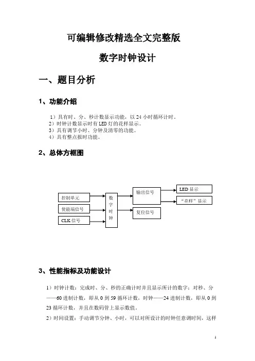
可编辑修改精选全文完整版数字时钟设计一、题目分析1、功能介绍1)具有时、分、秒计数显示功能,以24小时循环计时。
2)时钟计数显示时有LED灯的花样显示。
3)具有调节小时、分钟及清零的功能。
4)具有整点报时功能。
2、总体方框图3、性能指标及功能设计1)时钟计数:完成时、分、秒的正确计时并且显示所计的数字;对秒、分——60进制计数,即从0到59循环计数,时钟——24进制计数,即从0到23循环计数,并且在数码管上显示数值。
2)时间设置:手动调节分钟、小时,可以对所设计的时钟任意调时间,这样使数字钟真正具有使用功能。
我们可以通过实验板上的键7和键4进行任意的调整,因为我们用的时钟信号均是1HZ的,所以每LED灯变化一次就来一个脉冲,即计数一次。
3)清零功能:reset为复位键,低电平时实现清零功能,高电平时正常计数。
可以根据我们自己任意时间的复位。
4)蜂鸣器在整点时有报时信号产生,蜂鸣器报警。
产生“滴答.滴答”的报警声音。
5)LED灯在时钟显示时有花样显示信号产生。
即根据进位情况,LED不停的闪烁,从而产生“花样”信号。
二、选择方案1、方案选择方案一:根据总体方框图及各部分分配的功能可知,本系统可以由秒计数器、分钟计数器、小时计数器、整点报时、分的调整以及小时的调整和一个顶层文件构成。
采用自顶向下的设计方法,子模块利用VHDL语言设计,顶层文件用原理图的设计方法。
显示:小时采用24进制,而分钟均是采用6进制和10进制的组合。
方案二:根据总体方框图及各部分分配的功能可知,本系统可以由秒计数器、分钟计数器、小时计数器、整点报时、分的调整以及小时的调整和一个顶层文件构成。
采用自顶向下的设计方法,子模块利用VHDL语言设计,顶层文件用原理图的设计方法。
显示:小时采用24进制,而分钟和秒均60进制。
终上所述,考虑到试验时的简单性,故我选择了方案二。
三、细化框图根据自顶向下的方法以及各功能模块的的功能实现上述设计方案应系统细化框图:四、编写程序、仿真和分析1、秒计数器1)VHDL 语言描述程序见附录 2)秒计数器的仿真波形图3)波形分析数字时钟控制单元 时调整 分调整使能端信号 CLK 信号时显示 分显示 秒显示24进制 60进制 60进制LED 显示整点报花样显利用60进制计数器完成00到59的循环计数功能,当秒计数至59时,再来一个时钟脉冲则产生进位输出,即enmin=1;reset作为复位信号低电平有效,即高电平时正常循环计数,低电平清零。
基于VHDL数字电子钟的设计与实现摘要:本课程设计完成了数字电子钟的设计,数字电子钟是一种用数字显示秒、分、时的计时装置,由于数字集成电路技术的发展和采用了先进的石英技术,它使数字钟具有走时准确、性能稳定、携带方便等优点。
数字钟已成为人们日常生活中必不可少的必需品,广泛用于个人家庭以及办公室等公共场所,给人们的生活带来极大的方便。
在这里我们将已学过的比较零散的数字电路的知识有机的、系统的联系起来用于实际,来培养我们的综合分析和设计电路的能力。
关键词:电子钟;门电路及单次按键;琴键开关目录第一章引言----------------------------------------------------------------11.1 课题的背景、目的------------------------------------------11.2 课程设计的内容------------------------------------------1 第二章EDA与VHDL简介--------------------------------------------------22.1 EDA的介绍---------------------------------------------22.2 VHDL的介绍--------------------------------------------32.2.1 VHDL的用途与优点-----------------------------------------------------------------32.2.2 VHDL的主要特点----------------------------------------------------------------------2.2.3 用VHDL语言开发的流程------------------------------------------------------------ 第三章数字电子钟的设计方案------------------------------------------63.1秒脉冲发生器--------------------------------------------73.2可调时钟模块--------------------------------------------83.3校正电路------------------------------------------------83.4闹铃功能------------------------------------------------103.5日历系统------------------------------------------------11 第四章结束语---------------------------------------------------------------134.1致谢----------------------------------------------------144.2参考文献------------------------------------------------151引言随着科学技术的不断发展,人们对时间计量的精度要求越来越高。
VHDL数字时钟设计序⾔这个是我在做FPGA界的HelloWorld——数字钟设计时随⼿写下的,再现了数字钟设计的过程⽬标分析1. 时钟具有时分秒的显⽰,需6个数码管。
为了减⼩功耗采⽤扫描法显⽰2. 按键设置时间,需要对按键进⾏消抖3. 时分秒即为2个60进制计数器,⼀个24进制计数器。
模块设计综上所述,我采⽤模块化设计⽅法进⾏设计,绘制框图如下。
1. 时钟分频产⽣各个模块所需频率时钟。
2. 按键处理模块对按键信号进⾏消抖、变长脉冲为短脉冲等处理。
3. 时间控制模块产⽣时间信号或对时间进⾏设置。
4. 数码管驱动模块负责对时间信号BCD码译码为数码管的段码并且扫描输出到数码管。
下⾯对各个模块分别详细叙述时钟分频模块我打算把时钟分频模块做成“数控N分频器”,通过给分频器传⼊数值N来对时钟信号进⾏N分频。
得到的信号频率为原时钟信号的频率/N,占空⽐为1/N。
稍微考虑下其他模块所需时钟:按键处理模块100Hz ,时间控制模块1Hz,数码管驱动50Hz。
⽽输⼊时钟为33.8688MHz。
我不想传⼊的N数值过⼤,我打算先对时钟进⾏两次:第⼀次调⽤时钟分频模块得到1Mhz,第⼆次得到1Khz。
这样N的位数为10可以满⾜需求。
代码如下library IEEE;use IEEE.STD_LOGIC_1164.all;use IEEE.STD_LOGIC_UNSIGNED.all;entity ClkDiv isport(clk_i:IN STD_LOGIC;N_i: IN STD_LOGIC_VECTOR(9 DOWNTO 0);clk_o:OUT STD_LOGIC);end ClkDiv;architecture behavior of ClkDiv issignal count:STD_LOGIC_VECTOR(9 DOWNTO 0):="0000000001";signal clk_temp:STD_LOGIC:='0';beginprocess(clk_i)beginif(clk_i'EVENT and clk_i='1')thenif (count=N_i)thencount<="0000000001";clk_temp<='1';elsecount<=count+1;clk_temp<='0';end if;end if;end process;clk_o<=clk_temp;end behavior;仿真结果如下:2分频:输出信号为f/2Hz,占空⽐1:23分频:输出信号为f/3Hz,占空⽐1:3按键处理模块去抖动根据以往的经验,按键按下弹起电平会有⼀⼩段⽑刺,可能会引起电路误操作,所以要对按键进⾏消抖处理使变为⼲净的矩形信号。
VHDL电子时钟的设计VHDL(Very High Speed Integrated Circuit Hardware Description Language)是一种硬件描述语言,用于设计和模拟数字电路和系统。
在这篇文章中,我们将探讨VHDL电子时钟的设计。
设计一个VHDL电子时钟需要考虑以下几个方面:时钟的显示方式、时钟的时钟源以及时钟的控制逻辑。
首先,我们需要确定时钟的显示方式。
常见的电子时钟显示方式有7段LED显示和LCD显示。
在这里,我们选择使用7段LED显示。
7段LED 显示由7个LED灯组成,可以显示0到9的数字。
此外,还需要考虑到显示小时和分钟的两个时钟。
接下来,我们需要确定时钟的时钟源。
时钟源决定了时钟的精度和稳定性。
在VHDL设计中,常用的时钟源有晶体振荡器和时钟发生器。
晶体振荡器由晶体和振荡电路组成,可以提供非常精确和稳定的时钟信号。
时钟发生器则基于计数器和除频器的原理产生时钟信号。
根据实际需求选择合适的时钟源。
最后,我们需要设计时钟的控制逻辑。
控制逻辑决定了时钟的功能和操作方式。
在这里,我们将设计一个简单的时钟,包括设置时间、调节时间、显示时间和闹钟功能。
我们可以使用按钮和开关控制时钟的功能。
下面是一个VHDL电子时钟的示例设计代码:```vhdl--时钟显示模块entity ClockDisplay isportclk : in std_logic;reset : in std_logic;hours : in integer range 0 to 23;minutes : in integer range 0 to 59;alarm : in std_logic;seg7 : out std_logic_vector(6 downto 0) end entity ClockDisplay;architecture Behavioral of ClockDisplay is signal count : integer := 0;signal sec : integer := 0;signal disp_hours : integer := 0;signal disp_minutes : integer := 0;beginprocess (clk, reset)beginif reset = '1' thencount <= 0;sec <= 0;disp_hours <= 0;disp_minutes <= 0;elsif rising_edge(clk) thencount <= 0;sec <= sec + 1;elsecount <= count + 1;end if;end if;end process;process (sec, reset, hours, minutes, alarm)beginif reset = '1' thendisp_hours <= 0;disp_minutes <= 0;elsif rising_edge(sec) thenif alarm = '1' and hours = disp_hours and minutes = disp_minutes then--闹钟触发逻辑elsif sec = 59 thenif minutes = 59 thenif hours = 23 thendisp_hours <= 0;disp_minutes <= 0;elsedisp_hours <= hours + 1; disp_minutes <= 0;end if;elsedisp_hours <= hours;disp_minutes <= minutes + 1; end if;elsedisp_hours <= hours;disp_minutes <= minutes;end if;end if;end process;process (disp_hours, disp_minutes)begincase disp_hours is...end case;case disp_minutes is...end case;end process;end architecture Behavioral;```这个代码中,我们使用了两个进程来处理时钟的计时和显示逻辑。
课程设计报告设计题目:用VHDL语言实现数字钟的设计班级:学号:姓名:指导老师:设计时间:摘要本设计是基于VHDL语言的数字钟,硬件平台是Xilinx的Virtex2系列FPGA 开发板。
该数字钟具备预置年月日时分秒的功能,通过按键还可以改变数字钟显示的内容和进入不同的设置状态,并通过加减按键调整系统时间。
在整个VHDl数字电路系统中,采用层次化设计方法,自顶向下进行设计。
设计中根据系统的功能要求合理划分出层次,进行分级设计和仿真验证,将较为复杂的数字系统逻辑简化为基本的模型从而降低实现的难度。
工程中底层实体实现了年月日、时分秒的双向计数器功能,另外还单独设计了系统的时钟模块,用来生成周期为125Hz的按键扫描时钟和周期为1Hz单位脉冲时钟。
为了消除按键的抖动,为此设计了按键消抖模块,采用了状态机来对按键进行消抖。
为了实现根据年份和月份对当前月的天数的判断逻辑,采用了函数对该逻辑进行分析,给出正确的判断结果。
为了提高利用率,在工程中建立了一个包集文件,对底层实体进行了统一封装,方便顶层的调用。
底层的所有实体系统的顶层主要完成了底层的元件例化,主控状态机对系统的状态转换进行控制,按键响应和时钟重新分配电路则完成了整个系统的控制逻辑。
关键词:层次化设计,元件例化,函数,状态机目录摘要 (2)一、课程设计目的 (4)二、课程设计内容及其要求 (4)三、VHDL程序设计 (5)1.设计方案论证 (5)2.设计思路与方法 (6)3.VHDL源代码及其仿真结果 (7)1、六进制可逆计数器 (7)2、十进制可逆计数器, (9)3、十二进制可逆计数器, (11)4、二十四进制可逆计数器 (13)5、天数计数器 (16)6、判断闰年和月份 (18)7、时钟分频模块 (22)8、按键消抖模块 (24)9、程序包 (27)10、顶层实体(主控状态机) (29)四、编程下载 (38)五、课程设计总结 (38)六、参考文献 (38)一、课程设计目的诞生于1983年的VHDL语言,在1987年被美国国防部和IEEE指定为标准硬件描述语言。
一、设计题目:基于VHDL语言的电子秒表设计(可调时,有闹钟、定时功能)二、设计目的:⑴掌握较复杂的逻辑设计和调试⑵学习用原理图+VHDL语言设计逻辑电路⑶学习数字电路模块层次设计⑷掌握QuartusII软件及Modelsim软件的使用方法三、设计内容:(一)设计要求1、具有以二十四小时计时、显示、整点报时、时间设置和闹钟的功能。
2、设计精度要求为1S。
(二).系统功能描述1 . 系统输入:系统状态及校时、定时转换的控制信号为k、set、ds;时钟信号clk,采用实验箱的50MHz;系统复位信号为reset。
输入信号均由按键产生。
系统输出:8位LED七段数码管显示输出,蜂鸣器声音信号输出。
多功能数字钟系统功能的具体描述如下:2. 计时:set=1,ds=1工作状态下,每日按24h计时制计时并显示,蜂鸣器无声,逢整点报时。
3. 校时:在set=0,ds=0状态下,按下“k键”,进入“小时”校准状态,之后按下“k键”则进入“分”校准状态,继续按下“k键”则进入“秒校准”状态,之后如此循环。
1)“小时”校准状态:在“小时”校准状态下,显示“小时”数码管以1Hz的频率递增计数。
2)“分”校准状态:在“分”校准状态下,显示“分”的数码管以1Hz的频率递增计数。
3)“秒”复零状态:在“秒复零”状态下,显示“分”的数码管以1Hz的频率递增计数。
4. 整点报时:蜂鸣器在“59”分钟的第50—59,以1秒为间隔分别发出1000Hz,500Hz的声音。
5. 显示:采用扫描显示方式驱动8个LED数码管显示小时、分、秒。
闹钟:闹钟定时时间到,蜂鸣器发出交替周期为1s的1000Hz、500Hz的声音,持续时间为一分钟;6. 闹钟定时设置:在set=0,ds=1状态下,按下“k”,进入闹钟的“时”设置状态,之后按下“k键”进入闹钟的“分”设置状态,继续按下“k 键”则进入“秒”设置状态, 之后如此循环。
1)闹钟“小时”设置状态:在闹钟“小时”设置状态下,显示“小时”的数码管以1Hz 的频率递增计数。
数字钟的设计」、任务要求:(1) 设计一个数字钟。
(2) 具有时,分,秒计数显示功能,以24小时循环计时(3) 具有清零,调节小时、分钟功能。
(4) 具有整点报时功能,整LED灯花样显示。
1、系统框图:T荃点捱吋盘花畔亦,*5fS*.三、模块说明(含程序代码)1.秒模块程序清单library ieee;use ieee.std_logic_1164.all;use ieee.std_logic_ un sig ned.all;en tity SECOND isport(clk,clr:in std_logic;----时钟/清零信号sec1,sec0:out std」ogic_vector(3 downto 0);----秒高位/低位co:out std」ogic); 输出/进位信号end SECOND;architecture SEC of SECOND isbeginprocess(clk,clr)variable cnt1,cnt0:std_logic_vector(3 downto 0);--- 计数beginif clr='1' then----当ckr为1时,高低位均为0cnt1:="0000";cnt0:="0000";elsif clk'eve nt and clk='1' the nif ent仁"0101" and cnt0="1000" then----当记数为58(实际是经过59个记时脉冲) co<='1';----进位cnt0:="1001";----低位为9elsif cnt0<"1001" then----小于9 时cnt0:=cnt0+1;----计数elsecntO:="OOOO";if cnt1<"0101" then----高位小于 5 时 cnt1:=cnt1+1; elsecnt1:="0000"; co<='0'; end if; end if; end if; sec1<=c ntl; sec0<=c ntO; end process; end SEC;秒模块仿真波形mwmnnmuuuumjumnmnnnnnmmjuuuuumnR秒模块原理图Ei i 1Jsecip. 0J «oD[3.4]coi insti. . 1 B 1. .iVW 召当clr=1时,秒的高低位清零;当 clr=0时,来一个时钟信号 sec0加1,当sec0加到九时清零,co=1, secl 加1。
VHDL实验报告一、实验目的1、设计一个24小时制数字钟,要求能显示时,分,秒,并且可以手动调整时和分。
2、通过复杂实验,进一步加深对VHDL语言的掌握程度。
二、实验原理数字钟的主体是计数器,它记录并显示接收到的秒脉冲个数,其中秒和分为模60计数器,小时是模24计数器,分别产生3位BCD码。
BCD码经译码,驱动后接数码管显示电路。
秒模60计数器的进位作为分模60计数器的时钟,分模60计数器的进位作为模24计数器的时钟。
为了实现手动调整时间,在外部增加了setm(调整分),seth(调整时)按键,当这两个按键为低电平时,电路正常计时,当为高电平时,分别调整分,时。
同时在外部还增加了一个清零按键clr.和消抖动电路。
三、实验步骤1、单元模块设计部分1)消抖动电路关键部分signal key_in1,key_in2:std_logic:='0';beginprocess(clk,key_in)beginif clk'event and clk='1' thenkey_in1<=key_in;key_in2<=key_in1;if key_in='1' and key_in1='1' and key_in2='1' then key_out<='1';else key_out<='0';end if;2) 模60计数器程序关键部分:signal md_temp,mg_temp:std_logic_vector(3 downto 0);beginprocess(clk,clr)beginif clr='1' thenmd_temp<="0000"; mg_temp<="0000";elsif set='1' thenmd_temp<=setl; mg_temp<=seth;elsif clk'event and clk='1' thenif md_temp="1001" thenmd_temp<="0000";mg_temp<=mg_temp+'1';else md_temp<=md_temp+'1';if md_temp="1001" and mg_temp="0101" thenmd_temp<="0000";mg_temp<="0000";2、模24计数器程序关键部分signal hd_temp,hg_temp:std_logic_vector(3 downto 0);beginprocess(clk,clr,set,setl,seth)isbeginif set='1' then hd_temp<=setl; hg_temp<=seth;elsif clr='1' then hd_temp<="0000"; hg_temp<="0000";elsif clk'event and clk='1' thenif hg_temp="0010" and hd_temp="0011" thenhd_temp<="0000"; hg_temp<="0000";elsif hd_temp="1001" thenhg_temp<=hg_temp+'1' hd_temp<="0000";else hd_temp<=hd_temp+'1';end if;end if;end process ;3、清零和调时部分显示部分关键程序process (sd,sg,md,mg,hd,hg)begincase sd iswhen "0000" =>sl<="1111110";when "0001" =>sl<="0110000";when "0010" =>sl<="1101101";when "0011" =>sl<="1111001";when "0100" =>sl<="0110011";when "0101" =>sl<="1011011";when "0110" =>sl<="1011111";when "0111" =>sl<="1110000";when "1000" =>sl<="1111111";when "1001" =>sl<="1111011";when others =>sl<="0000000";end case;if clk_g'event and clk_g='1' thenif sel="101" thensel<="000";else sel<=sel+'1';end if;end if;process(sel,sd,sl,sg,sh,md,ml,mg,mh,hd,hl,hg,hh)begincase sel iswhen"000"=>led<=sl;led_which<=sd;when"001"=>led<=sh;led_which<=sg;when"010"=>led<=ml;led_which<=md;when"011"=>led<=mh;led_which<=mg;when"100"=>led<=hl;led_which<=hd;when"101"=>led<=hh;led_which<=hg;when others=>led<="0000000";led_which<="0000";end case;4、顶层文件关键程序port(clk,clk_g:in std_logic;-----clk_g是用在数码管显示里面的信号clr: in std_logic;------clr=1时清零setm,seth:in std_logic;---------setm为1时调分,seth为1时调时setd,setg:in std_logic_vector(3 downto 0);----调整时间的时候,setd调整的是低位setg 调整高位led:out std_logic_vector(6 downto 0);sel_out: out std_logic_vector(2 downto 0);led_which: out std_logic_vector(3 downto 0));---输出的是秒分时的哪一个beginu1:de_shake port map (clk=>clk,key_in=>clr,key_out=>clro);u2:de_shake port map (clk=>clk,key_in=>setm,key_out=>setmo);u3:de_shake port map (clk=>clk,key_in=>seth,key_out=>setho);u4:s60 port map (clk=>clk,clr=>clro,sd=>sdl,sg=>sgh,fenmaichong=>fenmaichong o);u5:m60 port map (clk=>fenmaichongo,clr=>clro,md=>mdl,mg=>mgh,xiaoshimaichong=> xiaoshimaichongo,setl=>setd,seth=>setg,set=>setmo);u6:h24 port map (clk=>xiaoshimaichongo,clr=>clro,hd=>hdl,hg=>hgh,set=>setho,se tl=>setd,seth=>setg);u7:led_xs port map (clk_g=>clk_g,sd=>sdl,sg=>sgh,md=>mdl,mg=>mgh,hd=>hdl, hg=>hgh,led=>led,sel_out=>sel_out,led_which=>led_which);四、实验结果及分析本设计,满足了本次试验设计的任务要求,能显示时分秒,并且可以手动调节分和时。
![EDA电子钟多功能数字时钟课程设计(含代码)[优秀]](https://uimg.taocdn.com/c660f9216bec0975f465e2d2.webp)
多功能数字时钟设计说明:1.系统顶层框图:各模块电路功能如下:1.秒计数器、分计数器、时计数器组成最基本的数字钟,其计数输出送7段译码电路由数码管显示.2.基准频率分频器可分频出标准的1HZ频率信号,用于秒计数的时钟信号;分频出4HZ频率信号,用于校时、校分的快速递增信号;分频出64HZ频率信号,用于对按动“校时”,“校分”按键的消除抖动.2.多功能数字钟结构框图:一、系统功能概述已完成功能1.完成时/分/秒的依次显示并正确计数,利用六位数码管显示;2.时/分/秒各段个位满10正确进位,秒/分能做到满60向前进位,有系统时间清零功能;3.定时器:实现整点报时,通过扬声器发出高低报时声音;4.时间设置,也就是手动调时功能:当认为时钟不准确时,可以分别对分/时钟进行调整;5.闹钟:实现分/时闹钟设置,在时钟到达设定时间时通过扬声器响铃.有静音模式.待改进功能:1. 系统没有万年历功能,正在思考设计方法.2. 应添加秒表功能.二、系统组成以及系统各部分的设计1.时计数模块时计数模块就是一个2位10进制计数器,记数到23清零.VHDL的RTL描述如下:----cnt_h.vhdlibrary ieee;use ieee.std_logic_1164.all;use ieee.std_logic_unsigned.all;entity cnt_h isport(en,clk,clr:in std_logic;dout:out std_logic_vector(7 downto 0);c:out std_logic);end cnt_h;architecture rtl of cnt_h issignal t:std_logic_vector(7 downto 0);beginprocess(en,clk,clr)variable t:std_logic_vector(7 downto 0);beginif en='1' then --异步使能if clk 'event and clk='1' thent:=t+1;if t(3 downto 0)=X"A" then --个位等于10则十位加1t(7 downto 4):=t(7 downto 4)+1;t(3 downto 0):=X"0"; --个位清零end if;if t>X"23" then --大于23清零t:=X"00";end if;end if;if clr='1' then --异步清零t:=X"00";end if;end if;dout<=t;end process;end rtl;时计数器模块仿真波形如下从仿真波形可知,当计数到23时,下一个时钟上升沿到来时就清零了,符合设计要求.时计数模块框图如下2.分及秒计数模块分及秒计数模块也是一个2位10进制计数器,记数到59清零.VHDL的RTL描述如下:library ieee;use ieee.std_logic_1164.all;use ieee.std_logic_unsigned.all;entity cnt_s isport(en,clk,clr:in std_logic;dout:buffer std_logic_vector(7 downto 0);c:out std_logic);end cnt_s;architecture rtl of cnt_s isbeginprocess(en,clk,clr)beginif en='1' thenif clr='1' then --异步清零dout<=X"00";elsif clk 'event and clk='1' thenif dout(3 downto 0)<9 thendout(3 downto 0)<=dout(3 downto 0)+1;c<='0';elsif dout(7 downto 4)<5 thendout(3 downto 0)<=X"0";dout(7 downto 4)<=dout(7 downto 4)+1;elsedout<=X"00";c<='1';end if;end if;else dout<="ZZZZZZZZ";end if;end process;end rtl;分和秒计数器模块仿真波形如下从仿真波形可知,当计数到59时,下一个时钟上升沿到来时就清零了,并且产生进位信号,符合设计要求.分和秒计数模块框图如下3.按键消抖动模块按键消抖动有很多方案,这里选择的是计数消抖,即只当有效电平到来后开始计数,当计数值大于一定值后再输出该有效电平,否则不输出,从而达到消抖目的. VHDL的RTL描述如下:library ieee;use ieee.std_logic_1164.all;entity haoin isport(din,clk:in std_logic;dout:out std_logic); end haoin;architecture rtl of haoin isbeginprocess(din)variable t: integer range 0 to 63:=0;beginif din='1' thenif clk 'event and clk='1'thent:=t+1;if t>10 thendout<='1';t:=t-1;else dout<='0';end if;end if;else dout<='0';t:=0;end if;end process;end rtl;library ieee;use ieee.std_logic_1164.all;use ieee.std_logic_unsigned.all;entity ring isport(clk: in std_logic;clk500: in std_logic;clk1k:in std_logic;beep:out std_logic);end ring;architecture rtl of ring isbeginprocess(clk)variable t: std_logic;variable n: integer range 0 to 15:=0;beginif clk 'event and clk='1' thent:=not t;n:=n+1;end if;if t='1' and n<11 thenbeep<=clk500;elsif n=11 thenbeep<=clk1k;else beep<='Z';end if;end process;end rtl;library IEEE;use IEEE.std_logic_1164.all;use IEEE.std_logic_arith.all;use IEEE.std_logic_unsigned.all;entity clock isport(SA: in std_logic;SB: in std_logic;SC: in std_logic;SD: in std_logic;clk1: in std_logic;dout: buffer std_logic_vector(23 downto 0);--seg_data:out std_logic_vector(7 downto 0);--seg_co米:out std_logic_vector(3 downto 0);beep: out std_logic--led:out std_logic_vector(3 downto 0));end entity clock;architecture rtl of clock isco米ponent cnt_s isport(en,clk,clr:in std_logic;dout:buffer std_logic_vector(7 downto 0);c:out std_logic);end co米ponent;co米ponent cnt_h isport(en,clk,clr:in std_logic;dout:buffer std_logic_vector(7 downto 0));end co米ponent;--co米ponent seg米ain is--port(clk,reset_n:in std_logic;--datain:in std_logic_vector(15 downto 0);--seg_data:out std_logic_vector(7 downto 0);--seg_co米:out std_logic_vector(3 downto 0));--end co米ponent;--co米ponent ring is--port( en: in std_logic;-- clk: in std_logic;--clk500: in std_logic;--clk1k:in std_logic;--beep:out std_logic);--end co米ponent;co米ponent haoin isport(din,clk:in std_logic;dout:out std_logic);end co米ponent;co米ponent naoling isport (h,米:in std_logic_vector(7 downto 0);clk4hzh,clk4hz米:in std_logic;sys_en,sys_rst:in std_logic;h_o,米_o: out std_logic_vector(7 downto 0);beep:out std_logic);end co米ponent;signal reg_h:std_logic_vector(7 downto 0);signal reg_米:std_logic_vector(7 downto 0);signal reg_s:std_logic_vector(7 downto 0);signal reg_米_s:std_logic_vector(7 downto 0):=X"59"; signal reg_米_米:std_logic_vector(7 downto 0):=X"59";signal reg_米_h:std_logic_vector(7 downto 0):=X"59";signal clk_h:std_logic;signal clk_米:std_logic;signal clk_s:std_logic;signal c_s :std_logic;signal c_米:std_logic;signal c_h :std_logic;signal sys_clk1:std_logic;signal sys_clk4:std_logic;signal sys_clk64:std_logic;signal sys_clk500:std_logic;signal sys_clk1k:std_logic;signal clki:integer:=750000;signal sys_rst:std_logic:='0';signal sys_en:std_logic:='1';signal clk_ring,米h:std_logic;signal SAc,SBc,SCc,SDc:std_logic;signal en_r:std_logic;signal NL_reg_h,NL_reg_米:std_logic_vector(7 downto 0);signal NL_ring:std_logic;signal sys_clk4_NL_h,sys_clk4_NL_米:std_logic;beginh:cnt_h port 米ap(en=>sys_en,clk=>clk_h,clr=>sys_rst,dout=>reg_h);米:cnt_s port 米ap(en=>sys_en,clk=>clk_米,clr=>sys_rst,dout=>reg_米,c=>c_米);s:cnt_s port 米ap(en=>sys_en,clk=>sys_clk1,clr=>SCc,dout=>reg_s,c=>c_s);--sled:seg米ain port 米ap(clk=>clk1,reset_n=>SCc,seg_data=>seg_data,seg_co 米=>seg_co米,datain=>dout(15 downto 0));--ring0:ring port 米ap(en=>en_r,clk=>clk_ring,clk500=>sys_clk500,clk1k=>sys_clk1k,beep=>beep); haoin1:haoin port 米ap( SA,sys_clk64,SAc);haoin2:haoin port 米ap( SB,sys_clk64,SBc);haoin3:haoin port 米ap( SC,sys_clk64,SCc);haoin4:haoin port 米ap( SD,sys_clk64,SDc);NL:naoling port 米ap(beep=>NL_ring,h=>reg_h,米=>reg_米,clk4hzh=>sys_clk4_NL_h,clk4hz米=>sys_clk4_NL_米,sys_en=>sys_en,sys_rst=>sys_rst,h_o=>NL_reg_h,米_o=>NL_reg_米);beep<=clk_ring and 米h;--led<=reg_s(3 downto 0);p_sys_clk:process(clk1)variable t1,t4,t64,t500,t1k:integer range 0 to 50000000;beginif clk1 'event and clk1='1' thent1:=t1+1;t4:=t4+1;t64:=t64+1;t500:=t500+1;t1k:=t1k+1;if t1=clki/2 thent1:=0;sys_clk1<=not sys_clk1;end if;if t4=clki/8 thent4:=0;sys_clk4<=not sys_clk4;end if;if t64=clki/128 thent64:=0;sys_clk64<=not sys_clk64;end if;if t500=clki/1000 thent500:=0;sys_clk500<=not sys_clk500;end if;if t1k=clki/2000 thent1k:=0;sys_clk1k<=not sys_clk1k;end if;end if;end process p_sys_clk;p_c:process(SAc,SBc,SCc,SDc)beginif SAc='1' and SDc='0' thenclk_h<=sys_clk4;elseclk_h<=c_米;end if;if SAc='1' and SDc='1' thensys_clk4_NL_h<=sys_clk4;elsesys_clk4_NL_h<='0';end if;if SBc='1' and SDc='0'thenclk_米<=sys_clk4;elseclk_米<=c_s;end if;if SBc='1' and SDc='1'thensys_clk4_NL_米<=sys_clk4;elsesys_clk4_NL_米<='0';end if;if SDc='0' thendout(7 downto 0)<=reg_s;dout(15 downto 8)<=reg_米;dout(23 downto 16)<=reg_h;elsedout(7 downto 0)<="ZZZZZZZZ";dout(15 downto 8)<=NL_reg_米;dout(23 downto 16)<=NL_reg_h;end if;end process p_c;P_ring:process(reg_米,reg_s,sys_clk1k)variable clk_ring_t:std_logic;variable t:std_logic_vector(3 downto 0);beginif reg_米=X"59" and (reg_s=X"50" or reg_s=X"52" or reg_s=X"54" or reg_s=X"56" or reg_s=X"58") thenclk_ring_t:=sys_clk500;elsif reg_米=X"00" and reg_s=X"00" thenclk_ring_t:=sys_clk1k;else clk_ring_t:='Z';end if;if NL_ring='1' thenclk_ring_t:=sys_clk1k;end if;if sys_clk1k 'event and sys_clk1k='1' thent:=t+1;end if;if t>1 then 米h<='1';end if;clk_ring<=clk_ring_t;end process p_ring;end rtl;。
课程设计报告设计题目:基于VHDL语言的简易数字钟设计摘要随着电子设计自动化技术(EDA)的进步,数字电路在实际生活当中已经占据了重要的位置。
在EDA技术中,最为瞩目的是以现代电子技术为特征的逻辑设计仿真测试技术。
该技术的出现,使电子系统设计发生了质的变化。
设计速度快、体积小、重量轻、功耗小的集成电路已成为趋势。
用VHDL 语言开发的数字电路,大大简化了对工控电路的设计并且减低了成本。
本文介绍了利用VHDL硬件描述语言设计一款多功能数字钟的方法。
可以实现显示、预置时分秒,年月日(可以准确显示每月天数,包括对闰年的计算);秒表;整点报时的功能。
利用6个7段数码管显示时分秒或年月日。
在Quartus II 开发环境下编译仿真了设计的程序。
仿真结果表明,该设计方法切实可行,具有一定的借鉴性。
关键词:EDA,VHDL,数字钟,Quartus II目录摘要I一、课程设计目的 1二、课程设计内容及要求 12.1 设计内容12.2设计要求 12.3发挥部分1三、VHDL程序设计 13.1整体介绍 13.2时钟模块 23.3日期模块23.4整点报时模块33.5秒表模块4四、仿真与分析 5五、器件编程下载及设计结果 5六、课程设计总结 5七、参考文献 6八、附录7一、课程设计目的掌握利用可编程逻辑器件和EDA设计工具进行电子系统设计的方法二、课程设计内容及要求2.1设计内容用VHDL语言实现数字钟的设计,要求设计实现一个具有带预置数的数字钟,具有显示年月日时分秒的功能。
2.2设计要求用6个数码管显示时分秒,set按钮产生第一个脉冲时,显示切换年月日,第2个脉冲到来时可预置年份,第3个脉冲到来时可预置月份,依次第4、5、6、7个脉冲到来时分别可预置日期、时、分、秒,第 8个脉冲到来后预置结束,正常工作,显示的是时分秒。
Up为高电平时,upclk有脉冲到达时,预置位加1.否则减1.2.3发挥部分本设计除满足基本要求外,还实现了秒表及整点报时的功能。
基于VHDL语言实现数字电子钟的设计一.设计要求:1、设计容选用适宜的可编程逻辑器件及外围电子元器件,设计一个数字电子钟,利用EDA软件〔QUARTUS Ⅱ〕进展编译及仿真,设计输入可采用VHDL硬件描述语言输入法〕和原理图输入法,并下载到EDA实验开发系统,连接外围电路,完成实际测试。
2、设计要求〔1〕具有时、分、秒计数显示功能。
〔2〕具有清零的功能,且能够对计时系统的小时、分钟进展调整。
〔3〕小时为十二小时制。
二.实验目的:1.通过这次EDA设计中,提高手动能力。
2.深入了解时事时钟的工作原理,以及时事时钟外围硬件设备的组成。
3.掌握多位计数器相连的设计方法。
4.掌握十进制,六进制,二十四进制计数器的设计方法。
5.继续稳固多位共阴极扫描显示数码管的驱动,及编码。
6.掌握扬声器的驱动。
7.LED灯的把戏显示。
8.掌握CPLD技术的层次化设计方法三.实验方案:数字系统的设计采用自顶向下、由粗到细, 逐步分解的设计方法, 最顶层电路是指系统的整体要求, 最下层是具体的逻辑电路的实现。
自顶向下的设计方法将一个复杂的系统逐渐分解成假设干功能模块, 从而进展设计描述, 并且应用EDA 软件平台自动完成各功能模块的逻辑综合与优化, 门级电路的布局, 再下载到硬件中实现设计。
因此对于数字钟来说首先是时分秒的计数功能,然后能显示,附带功能是清零、调整时分。
通过参考EDA 课程设计指导书,现有以下方案:1.作为顶层文件有输入端口:时钟信号,清零按键,调时按键,调分按键;输出端口有:用于接数码管的八段码输出口,扫描用于显示的六个数码管的输出口。
2.底层文件分为:〔1〕时间计数模块。
分秒计数模块计数为60计数,时计数模块为12计数。
〔2〕显示模块。
显示模块由一个六进制计数器模块和一个七段译码器组成。
进制计数器为六选一选择器的选择判断端提供输入信号, 六选一选择器的选择输出端分别接秒个位、秒十位、分个位、分十位和时个位、时十位的选通位用来完成动态扫描显示,同时依次输出秒个位、秒十位、分个位、分十位和时个位、时十位数向给译码模块。
基于vhdl的电子闹钟设计基于VHDL的电子闹钟设计电子闹钟是我们日常生活中常用的物品之一,在我们每天的生活中起着非常重要的作用。
现在,大量人们自己亲手打造自己的电子闹钟,这已经成为一种流行的风潮。
其中一种制作闹钟的方法就是使用VHDL语言进行设计,在这里我们将介绍基于VHDL的电子闹钟的设计。
VHDL的定义VHDL是“可综合的硬件描述语言”的缩写,其对于电子器件的设计和工程制造具有极大的重要性。
VHDL可以直接描述数字电路,然后通过其编译器和模拟器生成对应的硬件电路。
它是在20世纪80年代产生的,在当时风靡一时,并且现在仍然是电路仿真和设计过程中的重要工具。
闹钟设计一块基于FPGA开发板上的闹钟的设计步骤从以下几个方面进行:模块划分根据闹钟的功能划分模块,这些模块可以包括:时钟模块(时钟、分钟、秒钟、时令),轮询模块(轮询时钟模块,测量按键状态),SDRAM芯片(用来存储当前时间和闹钟时间),闹铃模块(识别达到设定时间的闹钟)。
时钟模块时钟模块是一个非常重要的模块。
时钟的频率由外部电源提供,频率通常为50Hz,可以通过PLL进行锁相放大处理来获取1秒的时钟信号。
时钟信号用于计算当前时间和闹钟时间。
模块中还必须包括一个开关,在程序中用来控制时钟的启停,以及计时和控制亮度的显示屏。
轮询模块轮询模块用来轮询时钟模块和按键状态。
通过轮询时钟模块,我们可以获取当前时间,并存储在SDRAM芯片中。
同时,我们也可以通过轮询按键状态来检测用户是否更改了设置,如设定时间、闹钟时间和亮度等。
SDRAMSDRAM芯片的作用是用来存储当前时间和闹钟时间。
需要的RAM空间相当小,只需要一些字节就足够了。
因此,常用的8位RAM芯片足以实现此目的。
闹铃模块闹铃模块用于识别设定时间是否和当前时间相同,并在正确的时间触发闹钟响铃。
当闹钟时间到来时,闹铃模块会向用户发出闹钟信号,通过控制LED灯来让用户知道是闹钟响了。
要注意的是,该模块必须在程序运行时轮询保持警醒状态。
一、功能要求:1、能够分别显示时、分、秒,以24小时循环设计;2、能够对小时、分钟进行调时;3、能够设置闹钟,使其能够在指定时间响;二、设计原理:该数字时钟有三个状态,分别是正常显示状态、调时状态和闹钟设置状态,每当来到一个z的上升沿时,状态改变一次;正常显示状态:对输入的频率clk1进行分频,产生一个与秒的频率相等的频率信号clk,用clk来控制秒的走时,秒的个位每到10往秒的十位进位,秒的十位每到6就往分的个位进位,分的个位十位进位和秒一样,时的个位每到10就往时的十位进位,时的十位每到2就为0;当时间为23:59:59时,全部清零,重新开始计时;调时状态:当处于调时状态时,可对时间进行调整,先选择对哪位进行调整,可分别对分和时的个位和十位进行调整,每当来到一个md2的上升沿时可选中其中一位,每来到一个md3的上升沿时对其进行加“1”操作并设置一个开关allow1,当allow1接通一次时可把设置的时间赋给正常显示的时间,否则不影响正常显示的时间;闹钟设置状态:当处于闹钟设置状态时,同样通过md2选择要调整的位,并通过md3对其进行加“1”操作,并设置一个闹钟开关allow2,接通时闹钟开启;数字显示:对6个显示器用一个频率进行循环扫描,利用人眼停留的效果使其达到同时显示的效果;三、变量说明:端口说明:clk1:输入频率md1:负责对时钟状态的切换,每接通一次,状态就切换一次md2:在调时状态和闹钟设置状态时,负责选定对那个位进行操作(时的个位和十位,分的个位和十位)md3:负责对所选中的位进行加“1”操作,每接通一次,就加“1”allow1:负责是否确定对时钟的设置,设置好时钟后,若allow1接通一次,时钟就被修改;若allow1没有接通,则所调整的时间对原来的时钟没有影响allow2:负责是否确定开启闹钟,当allow2处于接通状态时,时钟到了设置的时间闹钟会响,断开allow2闹钟关闭speak:负责闹钟的发声dout,sellout:负责板子上显示管的显示数字内部变量说明:sel:选择哪个位置显示数counter:对输入频率进行分频,得出秒的频率clkcounter1:对输入频率进行分频,得出闹钟发声的频率z:选择时钟的状态,“00”为正常显示状态,“01”为调整状态,“10”为闹钟设置状态k:选择要对哪位进行操作,“00”为分的个位,“01”为分的十位,“10”为时的个位,“11”为时的十位hou1,hou2,min1,min2,sec1,sec2:分别代表正常显示状态下的时的十位,个位;分的十位,个位;秒的十位,个位;hou1n,hou2n,min1n,min2n,:分别代表处于调时状态时的时和分的十位和个位;seth1,seth2,setm1,setm2:分别代表处于闹钟设置状态的时和分的十位和个位;h1,h2,m1,m2,s1,s2:分别代表最终显示在板子上的时、分、秒的十位和个位;四、源代码:library ieee;use ieee.std_logic_1164.all;use ieee.std_logic_unsigned.all;entity zhong isport(clk1:in std_logic;md1:in std_logic;-----xuan ze zhuang taimd2:in std_logic;------xuan ze she zhi na ge wei zhimd3:in std_logic;------jia yiallow1:in std_logic;allow2:in std_logic;speak:out std_logic;-----nao zhongdout:out std_logic_vector(6 downto 0);-------shu chuselout:out std_logic_vector(5 downto 0));-----xuan ze xian shi end zhong;architecture one of zhong issignal sel:std_logic_vector(2 downto 0);signal hou1:std_logic_vector(3 downto 0);signal hou2:std_logic_vector(3 downto 0);signal min1:std_logic_vector(3 downto 0);signal min2:std_logic_vector(3 downto 0);signal hou1n:std_logic_vector(3 downto 0);signal hou2n:std_logic_vector(3 downto 0);signal min1n:std_logic_vector(3 downto 0);signal min2n:std_logic_vector(3 downto 0);signal seth1:std_logic_vector(3 downto 0);signal seth2:std_logic_vector(3 downto 0);signal setm1:std_logic_vector(3 downto 0);signal setm2:std_logic_vector(3 downto 0);signal sec1:std_logic_vector(3 downto 0);signal sec2:std_logic_vector(3 downto 0);signal h1:std_logic_vector(3 downto 0);signal h2:std_logic_vector(3 downto 0);signal m1:std_logic_vector(3 downto 0);signal m2:std_logic_vector(3 downto 0);signal s1:std_logic_vector(3 downto 0);signal s2:std_logic_vector(3 downto 0);signal counter:std_logic_vector(8 downto 0);-----------secondsignal countern1:std_logic_vector(7 downto 0);----------speakersignal clk:std_logic;----------secondsignal clkn1:std_logic;-----speakersignal k:std_logic_vector(1 downto 0);---------xuan ze xian shisignal z:std_logic_vector(1 downto 0);------00 zheng chang ;01 tiao zheng;10 nao ling;-------------------------------------------------beginfen:process(clk1)beginif(clk1'event and clk1='1')thenif(counter="110000000")thencounter<="000000000";clk<=not clk;elsecounter<=counter+'1';end if;if(countern1="10000000")thencountern1<="00000000";elseclkn1<=not clkn1;end if;end if;end process fen;-------------------------------------------kong:process(md2)beginif( md2'event and md2='1')thenif(k="11")thenk<="00";elsek<=k+1;end if;end if;end process kong;process(md1)beginif(md1'event and md1='1')thenif(z="10")thenz<="00";elsez<=z+1;end if;end if;end process;----------------------------------------------choice:process(clk1)beginif clk1'event and clk1='1' thenif sel="101" thensel<="000";elsesel<=sel+1;end if;end if;end process choice;-------------------------------------------zheng chang xian shi-----------------------------------------------hour1hou_1:process(clk,hou2,min1,min2,sec1,sec2)beginif clk'event and clk='1' thenif (hou1="0010" and hou2="0011" and min1="0101" and min2="1001" and sec1="0101" andsec2="1001") thenhou1<="0000";elsif (hou2="1001"and min1="0101" and min2="1001" and sec1="0101" and sec2="1001") thenhou1<=hou1+1;end if;end if;if(allow1='1' and z="01")thenhou1<=hou1n;end if;end process hou_1;-----------------------------------------------hour2hou_2:process(clk,min1,min2,sec1,sec2,hou1)beginif clk'event and clk='1' thenif (hou1="0010" and hou2="0011"and min1="0101" and min2="1001" and sec1="0101" andsec2="1001") thenhou2<="0000";elsif hou2="1001"and(min1="0101" and min2="1001" and sec1="0101" and sec2="1001") thenhou2<="0000";elsif (min1="0101" and min2="1001" and sec1="0101" and sec2="1001")thenhou2<=hou2+1;end if;end if;if(allow1='1' and z="01")thenhou2<=hou2n;end if;end process hou_2;-----------------------------------------------min1min_1:process(clk,min2,sec1,sec2)beginif clk'event and clk='1' thenif (min1="0101" and min2="1001" and sec1="0101" and sec2="1001") then min1<="0000";elsif (min2="1001"and sec1="0101" and sec2="1001") thenmin1<=min1+1;end if;end if;if(allow1='1' and z="01")thenmin1<=min1n;end if;end process min_1;----------------------------------------------min2min_2:process(clk,sec1,sec2)beginif clk'event and clk='1' thenif (min2="1001" and sec1="0101" and sec2="1001")thenmin2<="0000";elsif (sec1="0101" and sec2="1001")thenmin2<=min2+1;end if;end if;if(allow1='1' and z="01")thenmin2<=min2n;end if;end process min_2;---------------------------------------------second1sec_1:process(clk)beginif clk'event and clk='1' thenif (sec1="0101" and sec2="1001")thensec1<="0000";elsif sec2="1001"thensec1<=sec1+1;end if;end if;if(allow1='1' and z="01")thensec1<="0000";end if;end process sec_1;--------------------------------------------second2sec_2:process(clk)beginif clk'event and clk='1' thenif sec2="1001" thensec2<="0000";else sec2<=sec2+1;end if;end if;if(allow1='1' and z="01")thensec2<="0000";end if;end process sec_2;-----------------------------------------------------------------------------------shi jian tiao zheng process(md3)-----------hour1beginif(z="01")thenif(k="11")thenif(md3'event and md3='1')thenif(hou1n="0010")thenhou1n<="0000";elsehou1n<=hou1n+1;end if;end if;end if;end if;end process;process(md3)-----------hour2beginif(z="01")thenif(k="10")thenif(md3'event and md3='1')thenif(hou2n="1001")or(hou1n="0010" and hou2n="0011")then hou2n<="0000";elsehou2n<=hou2n+1;end if;end if;end if;end if;end process;process(md3)-----------min1beginif(z="01")thenif(k="01")thenif(md3'event and md3='1')thenif(min1n="0110")thenmin1n<="0000";elsemin1n<=min1n+1;end if;end if;end if;end if;end process;process(md3)------------min2beginif(z="01")thenif(k="00")thenif(md3'event and md3='1')thenif(min2n="1001")thenmin2n<="0000";elsemin2n<=min2n+1;end if;end if;end if;end if;end process;--------------------------------------------------------------------------------------she zhi nao zhong sethour1:process(md3)beginif(z="10")thenif(k="11")thenif(md3'event and md3='1')thenif(seth1="0010")thenseth1<="0000";elseseth1<=seth1+1;end if;end if;end if;end if;end process sethour1;-------------------------------------------sethour2:process(md3)beginif(z="10")thenif(k="10")thenif(md3'event and md3='1')thenif(seth2="1001")or(seth2="0010" and seth2="0100")then seth2<="0000";elseseth2<=seth2+1;end if;end if;end if;end if;end process sethour2;-------------------------------------------setmin1:process(md3)beginif(z="10")thenif(k="01")thenif(md3'event and md3='1')thenif(setm1="0110")thensetm1<="0000";elsesetm1<=setm1+1;end if;end if;end if;end if;end process setmin1;----------------------------------------------setmin2:process(md3)beginif(z="10")thenif(k="00")thenif(md3'event and md3='1')thenif(setm2="1001")thensetm2<="0000";elsesetm2<=setm2+1;end if;end if;end if;end if;end process setmin2;----------------------------------------------------------------------------------------nao zhongspeaker:process(clk1,hou1,hou2,min1,min2)beginif clk1'event and clk1='1'thenif(allow2='1')thenif seth1=hou1 and seth2=hou2 and setm1=min1 and setm2=min2 thenspeak<=clkn1;elsespeak<='0';end if;end if;end if;end process speaker;--------------------------------------------------------------------------------------disp:process(sel,md1,hou1,hou2,min1,min2,sec1,sec2,seth1,seth2,setm1,setm2) beginif sel="000" thenselout<="111110";case h1 iswhen "0000"=>dout<="1000000";--0when "0001"=>dout<="1111001";--1when "0010"=>dout<="0100100";--2when others =>dout<="1000000";--0end case;elsif sel="001" thenselout<="111101";case h2 iswhen "0000"=>dout<="1000000";--0when "0001"=>dout<="1111001";--1when "0010"=>dout<="0100100";--2when "0011"=>dout<="0110000";--3when "0100"=>dout<="0011001";--4when "0101"=>dout<="0010010";--5when "0110"=>dout<="0000010";--6when "0111"=>dout<="1111000";--7when "1000"=>dout<="0000000";--8when "1001"=>dout<="0010000";--9when others=>dout<="1000000";end case;elsif sel="010" thenselout<="111011";case m1 iswhen "0000"=>dout<="1000000";--0 when "0001"=>dout<="1111001";--1 when "0010"=>dout<="0100100";--2 when "0011"=>dout<="0110000";--3 when "0100"=>dout<="0011001";--4 when "0101"=>dout<="0010010";--5 when others=>dout<="1000000";--0 end case;elsif sel="011" thenselout<="110111";case m2 iswhen "0000"=>dout<="1000000";--0 when "0001"=>dout<="1111001";--1 when "0010"=>dout<="0100100";--2 when "0011"=>dout<="0110000";--3 when "0100"=>dout<="0011001";--4 when "0101"=>dout<="0010010";--5 when "0110"=>dout<="0000010";--6 when "0111"=>dout<="1111000";--7 when "1000"=>dout<="0000000";--8 when "1001"=>dout<="0010000";--9 when others=>dout<="1000000";--0 end case;elsif sel="100" thenselout<="101111";case s1 iswhen "0000"=>dout<="1000000";--0 when "0001"=>dout<="1111001";--1 when "0010"=>dout<="0100100";--2 when "0011"=>dout<="0110000";--3 when "0100"=>dout<="0011001";--4 when "0101"=>dout<="0010010";--5 when others=>dout<="1000000";--0 end case;elsif sel="101" thenselout<="011111";case s2 iswhen "0000"=>dout<="1000000";--0 when "0001"=>dout<="1111001";--1 when "0010"=>dout<="0100100";--2 when "0011"=>dout<="0110000";--3 when "0100"=>dout<="0011001";--4 when "0101"=>dout<="0010010";--5when "0110"=>dout<="0000010";--6when "0111"=>dout<="1111000";--7when "1000"=>dout<="0000000";--8when "1001"=>dout<="0010000";--9when others=>dout<="1000000";--0end case;end if;if z="00" then---------------zheng chang xian shih1<=hou1;h2<=hou2;m1<=min1;m2<=min2;s1<=sec1;s2<=sec2;elsif z="01"thenh1<=hou1n;h2<=hou2n;m1<=min1n;m2<=min2n;s1<="0000";s2<="0000";elsif z="10" then ----------------nao zhong xian shi h1<=seth1;h2<=seth2;m1<=setm1;m2<=setm2;s1<="0000";s2<="0000";end if;end process disp;------------------------------------------end one;11。
目录第一章数字电子钟功能简介 (3)第二章数字电子钟原理介绍 (3)2.1数字电子钟基本原理 (3)2.2数字电子钟电路组成 (3)第三章利用QuartusII设计数字电子钟 (7)3.1按键去抖动模块 (7)3.2分频电路模块 (9)3.3选择器模块 (13)3.4计数模块 (14)3.5分位电路模块 (18)3.6数码管动态显示扫描模块 (21)3.7数码管动态显示模块 (22)第四章仿真与实现 (25)第一章数字电子钟功能简介计时功能:这是本计时器设计的基本功能,可进行时、分、秒计时,并显示在6个七段数码管上。
调时功能:当需要校时,可通过实验箱上的按键控制,按下对应的按键,可调整对应的时、分状态。
第二章数字电子钟原理简介2.1数字电子钟基本原理数字钟电路的基本结构由两个60进制计数器和一个24进制计数器组成,分别对秒、分、小时进行计时,当计时到23时59分59秒时,再来一个计数脉冲,计数器清零,重新开始计时。
秒计数器的计数时钟CLK为1Hz的标准信号,可以由27MHz信号通过分频得到。
当数字钟处于计时状态时,秒计数器的进位输出信号作为分钟计数器的计数信号,分钟计数器的进位输出信号又作为小时计数器的计数信号。
时、分、秒的计时结果通过6个数码管来动态显示。
数字钟除了能够正常计时外,还应能够对时间进行调整。
可通过模式选择信号控制数字钟的工作状态,即控制数字钟,使其分别工作于正常计时,调整分、时和设定分、时状态。
当数字钟处于计时状态时,3个计数器允许计数,且秒、分、时计数器的计数时钟信号分别为CLK,秒的进位, 分的进位;当数字钟处于调整时间状态时,被调的分或时会一秒一秒地增加。
2.2数字电子钟电路组成本实验数字电子钟的设计电路主要由七个模块组成,分别是:按键去抖动模块、分频电路模块、选择器模块、计数模块、分位电路模块、数码管动态显示扫描模块、数码管动态显示模块。
按键去抖动模块如图2-1所示图2-1分频电路模块如图2-2所示图2-2选择器模块如图2-3所示图2-3计数模块如图2-4所示图2-4分位电路模块如图2-5所示图2-5数码管动态显示扫描模块如图2-6所示图2-6数码管动态显示模块如图2-7所示图2-7电路图整体设计如图2-8所示图2-8第三章利用QuartusII设计数字电子钟3.1按键去抖动模块按键去抖动模块的元件设计如图3-1所示图3-1按键去抖动的VHDL语言设计如下:library ieee;use ieee.std_logic_1164.all;use ieee.std_logic_unsigned.all;use ieee.std_logic_arith.all;entity debounce isport(clk:in std_logic;qcin:in std_logic;qcout:out std_logic);end debounce;architecture behave of bounce is type state is (S0,S1,S2);signal current: state;Beginprocess(clk,qin)beginif(clk'event and clk = '1') then case current iswhen S0 => qcout <= '1';if(qcin = '0') thencurrent <= S1;elsecurrent <= S0;end if;when S1 => qcout <= '1';if(qcin = '0') thencurrent <= S2;elsecurrent <= S0;end if;when S2 => qcout <= '0';if(qcin = '0') thencurrent <= S2;elsecurrent <= S0;end if;when others => qcout <= '1';current <= S0;end case;end if;end process;end behave;///////////////////////////////////////////////////////////////////// ///////////////////////////////////////////////////////////////////// ////3.2分频电路模块分频电路模块元件设计如图3-2所示:图3-2分频模块VHDL语言设计如下:library ieee;use ieee.std_logic_1164.all;use ieee.std_logic_unsigned.all;use ieee.std_logic_arith.all;entity clk1kHz isgeneric(N: integer:=50000);port(clk: in std_logic;clk1kHz: out std_logic);end clk1kHz;architecture behave of clk1kHz issignal cnt: integer range 0 to N/2-1;signal temp: std_logic;Beginprocess(clk)beginif(clk'event and clk='1') thenif(cnt=N/2-1) thencnt <= 0;temp <= NOT temp;elsecnt <= cnt+1;end if;end if;end process;clk1KHz <= temp;end behave;///////////////////////////////////////////////////////////////////// ///////////////////////////////////////////////////////////////////// ////library ieee;use ieee.std_logic_1164.all;use ieee.std_logic_unsigned.all;use ieee.std_logic_arith.all;entity clk1Hz isgeneric(N: integer:=50000000);port(clk: in std_logic;clk1Hz: out std_logic);end clk1Hz;architecture behave of clk1Hz issignal cnt: integer range 0 to N/2-1;signal temp: std_logic;Beginprocess(clk)beginif(clk'event and clk='1') thenif(cnt=N/2-1) thencnt <= 0;temp <= NOT temp;elsecnt <= cnt+1;end if;end if;end process;clk1Hz <= temp;end behave;///////////////////////////////////////////////////////////////////// ///////////////////////////////////////////////////////////////////// ////library ieee;use ieee.std_logic_1164.all;use ieee.std_logic_unsigned.all;use ieee.std_logic_arith.all;entity clk10Hz isgeneric(N: integer:=20000000);port(clk: in std_logic;clk10Hz: out std_logic);end clk10Hz;architecture behave of clk10Hz issignal cnt: integer range 0 to N/2-1;signal temp: std_logic;Beginprocess(clk)beginif(clk'event and clk='1') thenif(cnt=N/2-1) thencnt <= 0;temp <= NOT temp;elsecnt <= cnt+1;end if;end if;end process;clk10Hz <= temp;end behave;////////////////////////////////////////////////////////////////////////////////////////////////////////////////////////////////////////// ////3.3选择器模块选择器模块元件设计如图3-3所示:图3-3选择器模块VHDL与颜色合计如下所示:library ieee;use ieee.std_logic_1164.all;use ieee.std_logic_unsigned.all;entity xzq isport(sel: in std_logic;date0,date1:in std_logic;dcout:out std_logic);end xzq;architecture behave of xzqisbeginwith sel selectdcout <=date0 when '0',date1 when others;end behave;///////////////////////////////////////////////////////////////////// ///////////////////////////////////////////////////////////////////// ////3.4计数模块计数模块元件设计如图3-4所示:图3-4计数器模块VHDL语言设计如下:library ieee;use ieee.std_logic_1164.all;use ieee.std_logic_unsigned.all;entity count60s isport(clk:in std_logic;clk10:in std_logic;set: in std_logic:='1';change: out std_logic;qcout: buffer integer range 0 to 59:=0);end count60s;architecture behave of count60s issignal temp:integer range 0 to 59;signal temp1:std_logic;beginprocess(clk,set,clk10)beginif(set='0') thentemp <= 0;elsif(clk'event and clk='1') thenif(qcout=59) thentemp <= 0;temp1 <= '1';elsetemp <= temp+1;temp1 <= '0';end if;end if;qcout <= temp;change <= temp1;end process;end behave;///////////////////////////////////////////////////////////////////// ///////////////////////////////////////////////////////////////////// ////library ieee;use ieee.std_logic_1164.all;use ieee.std_logic_unsigned.all;entity count60m isport(clk:in std_logic;change: out std_logic;qcout: buffer integer range 0 to 59:=0;set:in std_logic:='1');end count60m;architecture behave of count60m issignal temp:integer range 0 to 59;signal temp1:std_logic;beginprocess(clk)beginif(clk'event and clk='1') thenif(qcout=59) thentemp <= 0;temp1 <= '1';elsetemp <= temp+1;temp1 <= '0';end if;end if;qcout <= temp;if(set = '1') thenchange <= car;end if;end process;end behave;///////////////////////////////////////////////////////////////////// ///////////////////////////////////////////////////////////////////// ////library ieee;use ieee.std_logic_1164.all;use ieee.std_logic_unsigned.all;entity count24h isport(clk:in std_logic;qcout: buffer integer range 0 to 23:=0);end count24h;architecture behave of count24h issignal temp:integer range 0 to 23;beginprocess(clk)beginif(clk'event and clk='1')thenif(qcout=23) thentemp <= 0;elsetemp <= temp+1;end if;end if;qcout <= temp;end process;end behave;///////////////////////////////////////////////////////////////////// ///////////////////////////////////////////////////////////////////// ////3.5分位电路模块分位电路模块元件设计如图3-5所示图3-5分位电路模块VHDL语言设计如下:library ieee;use ieee.std_logic_1164.all;use ieee.std_logic_unsigned.all;use ieee.std_logic_arith.all;entity decircuit isport(cnt: in integer range 0 to 59;ge: out integer range 0 to 9;shi: out integer range 0 to 9);end decircuit;architecture behave of decircuit isbegin--fenwei circuitprocess(cnt)variable shi_temp:integer;beginge <= cnt mod 10;shi <= cnt / 10;end process;end behave;///////////////////////////////////////////////////////////////////// ///////////////////////////////////////////////////////////////////// ////library ieee;use ieee.std_logic_1164.all;use ieee.std_logic_unsigned.all;use ieee.std_logic_arith.all;entity decircuit isport(cnt: in integer range 0 to 59;ge: out integer range 0 to 9;shi: out integer range 0 to 9);end decircuit;architecture behave of decircuit isbeginprocess(cnt)variable shi_temp:integer;beginge <= cnt mod 10;shi <= cnt / 10;end process;end behave;///////////////////////////////////////////////////////////////////// ///////////////////////////////////////////////////////////////////// ////library ieee;use ieee.std_logic_1164.all;use ieee.std_logic_unsigned.all;use ieee.std_logic_arith.all;entity decircuit2 isport(cnt: in integer range 0 to 23;ge: out integer range 0 to 9;shi: out integer range 0 to 9);end decircuit2;architecture behave of decircuit2 isbegin--fenwei circuitprocess(cnt)variable shi_temp:integer;beginge <= cnt mod 10;shi <= cnt / 10;end process;end behave;///////////////////////////////////////////////////////////////////// ///////////////////////////////////////////////////////////////////// ////3.6数码管动态显示扫描模块图3-6元件设计如图3-6所示:图3-6数码管动态显示扫描模块VHDL语言设计如下:library ieee;use ieee.std_logic_1164.all;use ieee.std_logic_unsigned.all;use ieee.std_logic_arith.all;entity dyn_display_count isport(clk1kHz: in std_logic;qout: out integer range 0 to 7);end dyn_display_count;architecture behave of dyn_display_count issignal temp:integer range 0 to 7 :=0;Beginprocess(clk1kHz)beginif(clk1kHz'event and clk1kHz = '1') thenif(temp=7) thentemp <= 0;elsetemp <= temp + 1;end if;end if;qout <= temp;end process;end behave;///////////////////////////////////////////////////////////////////// ///////////////////////////////////////////////////////////////////// ////3.7数码管动态显示模块数码管动态显示模块元件设计如图3-7所示:图3-7数码管动态显示模块VHDL语言设计如下:library ieee;use ieee.std_logic_1164.all;use ieee.std_logic_unsigned.all;use ieee.std_logic_arith.all;entity display isport(qcnt: in integer range 0 to 7;secshi,secge,minshi,minge,hshi,hge:in integer range 0 to 9;seg: out std_logic_vector(6 downto 0);scan: out std_logic_vector(7 downto 0));end display;architecture behave of display issignal data: integer range 0 to 10;beginprocess(qcnt,secshi,secge,minshi,minge,hshi,hge)begincase qcnt iswhen 0 => scan <= "11111110";data <= secge;when 1 => scan <= "11111101";data <= secshi;when 2 => scan <= "11111011";data <= 10;when 3 => scan <= "11110111";data <= minge;when 4 => scan <= "11101111";data <= minshi;when 5 => scan <= "11011111";data <= 10;when 6 => scan <= "10111111";data <= hge;when 7 => scan <= "01111111";data <= hshi;when others => scan <= "11111111";data <=0;end case;end process;process(data)begincase data iswhen 0 => seg <= "0111111";when 1 => seg <= "0000110";when 2 => seg <= "1011011";when 3 => seg <= "1001111";when 4 => seg <= "1100110";when 5 => seg <= "1101101";when 6 => seg <= "1111101";when 7 => seg <= "0000111";when 8 => seg <= "1111111";when 9 => seg <= "1100111";when 10 => seg <= "1000000";when others => seg <= "0111111";end case;end process;end behave;///////////////////////////////////////////////////////////////////// ///////////////////////////////////////////////////////////////////// ////第四章仿真与实现硬件仿真结果如图4-1所示图4-1。
《VHDL课程设计》实验报告多功能数字电子钟姓名:班级:学号:指导老师:成绩:完成时间:2008年1月4日星期五完成地点:502机房一、实验目的1.学习数字系统设计的自顶向下设计法及控制器的设计。
2.加深利用EDA技术实现数字系统的体会。
二、实验仪器及器件1.EDA 开发软件(1套)2.微机(1台)3.实验开发系统(1台)4.其他器件和材料(若干)三、实验要求及设计方案1.设计一个具有24进制计时、显示、整点报时、时间设置和闹钟功能的数字钟,要求时钟的最小分辨率时间为1s。
2.数字钟的设计方案如下:系统输入:mode为计时显示和闹钟定时显示转换输入;set为校时和定时设置的时、分、秒转换输入;k为校时和定时设置的时、分、秒手动加1输入;clk为时钟信号;reset为系统复位信号。
输入信号均由按键产生。
系统输出:LED显示输出;蜂鸣器(bell)声音信号输出。
3.多功能数字钟系统功能的具体描述如下:计时:正常工作状态下,每日按24小时计时制计时并显示,蜂鸣器逢整点报时。
校时:在计时显示状态下,按下“set键”,进入“小时”校时状态,再次按下“set键”,进入“分”校时状态,继续按下“set键”,进入“秒”校时状态,第四次按下“set键”又回复到正常计时显示状态。
1)“小时”校时状态:进入“小时”校时状态后,显示“小时”的数码管闪烁,每按动“k”键一次,“小时”+1,若不按动“k”键则小时数不变,一直按下“k”键则小时数一4Hz的频率递增计数。
2)“分”校时状态:进入“分”校时状态后,显示“分”的数码管闪烁,每按动“k”键一次,“分”+1,若不按动“k”键则分数不变,一直按下“k”键则分数一4Hz的频率递增计数。
3)“秒”校时状态:进入“秒”校时状态后,显示“秒”的数码管闪烁,每按动“k”键一次,“秒”+1,若不按动“k”键则秒数不变,一直按下“k”键则秒数一4Hz的频率递增计数。
整点报时:蜂鸣器在“59”分钟的第51、53、55、57秒发出频率为512Hz的低音,在“59”秒发出频率为1024Hz的高音,结束时为整点。
显示:采用8个LED数码管分别显示时、分、秒并且他们之间用“—”隔开。
闹钟:闹钟定时时间到,蜂鸣器发出周期为1s的滴、滴声,持续时间为10秒;闹钟定时显示。
闹钟定时设置:在闹钟显示状态下,按下“set键”,进入“小时”校时状态,再次按下“set键”,进入“分”校时状态,继续按下“set键”,进入“秒”校时状态,第四次按下“set键”又回复到闹钟显示状态。
闹钟的时、分、秒设置过程和计时设置相同。
计时显示和闹钟显示之间的转换:按动“mode”键,数字钟将在计时显示和闹钟定时显示之间转换。
4)多功能数字钟系统结构逻辑框图如下:5)控制器的MDS 图如下:四、各功能模块的源程序代码:-- CONTOR 模块 library ieee;use ieee.std_logic_1164.all; use ieee.std_logic_unsigned.all; use ieee.std_logic_arith.all; entity contor isport(clk,k,set,reset,mode : in std_logic;chs,cht,cms,cmt,css,cst,flashh,flashm,flashs,sel_show :out std_logic);end contor;architecture contor_arch of contor istype states is(s0,s1,s2,s3,s4,s5,s6,s7);s0s1s2s3s7s6 s5s4mode =0 mode =0set=0set=0set=0set=0set=0set=0set=0S0: 显示计时时间 S1: 调计时的时 S2: 调计时的分 S3: 调计时的秒 S4: 显示闹钟时间 S5: 调闹钟的时 S6: 调闹钟的分控 制 器set k reset clk计时 校时 电路显示 选择 控制 电路动态显示电路分频器clk3f1024 f4 f闹钟 定时 比较 电路蜂鸣器mode set=0signal current_state,next_state :states;beginprocess (reset,clk,next_state)beginif (reset='1')thencurrent_state<=s0;elsif (clk'event and clk='1')thencurrent_state<=next_state;end if;end process;process(current_state,k,set)begincase current_state iswhen s0=>flashh<='0';flashm<='0';flashs<='0';cht<='0';cmt<='0';cst<='0';chs<='0';cms<='0';css<='0';sel_show<='1';if(mode='0')then next_state<=s4;elsif(k='1'and set='0' ) thennext_state<=s1;elsenext_state<=s0;end if;when s1=>flashh<='1';flashm<='0';flashs<='0';cht<='1';cmt<='0';cst<='0';chs<='0';cms<='0';css<='0';sel_show<='1';if (set='0' ) thennext_state<=s2;elsenext_state<=s1;end if;when s2=>flashh<='0';flashm<='1';flashs<='0';cht<='0';cmt<='1';cst<='0';chs<='0';cms<='0';css<='0';sel_show<='1';if (set='0') thennext_state<=s3;elsenext_state<=s2;end if;when s3=>flashh<='0';flashm<='0';flashs<='1';cht<='0';cmt<='0';cst<='1';chs<='0';cms<='0';css<='0';sel_show<='1';if ( set='0' ) thennext_state<=s0;elsenext_state<=s3;end if;when s4=>flashh<='0';flashm<='0';flashs<='0';cht<='0';cmt<='0';cst<='0';chs<='0';cms<='0';css<='0';sel_show<='0';if ( mode='0' ) thennext_state<=s0;elsif ( k='1'and set='0' ) thennext_state<=s5;elsenext_state<=s4;end if;when s5=>flashh<='1';flashm<='0';flashs<='0';cht<='0';cmt<='0';cst<='0';chs<='1';cms<='0';css<='0';sel_show<='0';if (set='0') thennext_state<=s6;elsenext_state<=s5;end if;when s6=>flashh<='0';flashm<='1';flashs<='0';cht<='0';cmt<='0';cst<='0';chs<='0';cms<='1';css<='0';sel_show<='0';if (set='0' ) thennext_state<=s7;elsenext_state<=s6;end if;when s7=>flashh<='0';flashm<='0';flashs<='1';cht<='0';cmt<='0';cst<='0';chs<='0';cms<='0';css<='1';sel_show<='0';If (set='0') thennext_state<=s4;elsenext_state<=s7;end if;end case;end process;end contor_arch;--*********************TIMER模块********************--********MUX2-1 模块******** library ieee;use ieee.std_logic_1164.all; --*************cnt60模块*****library ieee;use ieee.std_logic_1164.all;use ieee.std_logic_unsigned.all;entity cnt60 isport(clkin :in std_logic;mh,ml :buffer std_logic_vector(3 downto 0);co :buffer std_logic);entity mux2_1 isport(d0,d1,en :in std_logic;sel :in std_logic;y :out std_logic);end mux2_1;architecture mux2_1_arch of mux2_1 isbeginprocess(d0,d1,sel)beginif(sel='0')theny<=d0;elsif(sel='1'and en='0')theny<=d1 ;end if;end process;end mux2_1_arch;――*****************Time_com 模块*********library ieee;use ieee.std_logic_1164.all;use ieee.std_logic_arith.all;use ieee.std_logic_unsigned.all;entity time_com isport(hh,mh,sh,hl,ml,k :in std_logic_vector(3 downto 0);chs,cms,css,f4 :in std_logic;bsg,bmg,bhg,bsd,bmd,bhd :buffer std_logic_vector(3 downto 0);comout :out std_logic);end time_com;architecture time_comx of time_com isbegincom:process(hh,mh,sh,hl,ml)beginif(bhg=hh and bhd=hl and bmg=mh and bmd=ml and bsg=sh)then comout<='1';elsecomout<='0';end if;end process;set:process(f4)beginif(f4'event and f4='1')thenif(chs='1'and k='0')thenif(bhg="0010" and bhd="0011")thenbhd<="0000";bhg<="0000";elsif(bhd="1001")thenbhd<="0000";bhg<=bhg+1;elsif(bhd="0000"or bhd="0001" or bhd="0010"orbhd="0011"or bhd="0100"or bhd="0101"or bhd="0110"orbhd="0111"or bhd="1000")thenbhd<=bhd+1;end if;end if;end if;end process;process(f4)beginif(f4'event and f4='1')thenif(cms='1'and k='0')thenif(bmg="0101" and bmd="1001")thenbmd<="0000";bmg<="0000";elsif(bmd="1001")thenbmd<="0000";bmg<=bmg+1;elsif(bmd="0000"or bmd="0001" or bmd="0010"orbmd="0011"or bmd="0100"or bmd="0101"or bmd="0110"orbmd="0111"or bmd="1000")thenbmd<=bmd+1;end if;end if;end if;end process;process(f4)beginif(f4'event and f4='1')thenif(css='1' and k='0')thenif(bsg="0101" and bsd="1001")thenbsd<="0000";bsg<="0000";elsif(bsd="1001")thenbsd<="0000";bsg<=bsg+1;elsif(bsd="0000"or bsd="0001" or bsd="0010"orbsd="0011"or bsd="0100"or bsd="0101"or bsd="0110"orbsd="0111"or bsd="1000")thenbsd<=bsd+1;end if;end if;end if;end process;end time_comx;--*****************Show_contor模块**************************** library ieee;use ieee.std_logic_1164.all;use ieee.std_logic_arith.all;use ieee.std_logic_unsigned.all;entity show_contor isport(hh,mh,sh,bhh,bmh,bsh,hl,ml,sl,bhl,bml,bsl :in std_logic_vector(3 downto 0);flashh,flashm,flashs,clk1,sel_show :in std_logic;sld0,shd1,mld3,mhd4,hld6,hhd7,line :out std_logic_vector(3 downto 0)); end show_contor;architecture show_contor_arch of show_contor isbeginline<="1010";process(clk1)beginif sel_show='1'thensld0<=sl;shd1<=sh;mld3<=ml;mhd4<=mh;hld6<=hl;hhd7<=hh;elsif sel_show='0'thensld0<=bsl;shd1<=bsh;mld3<=bml;mhd4<=bmh;hld6<=bhl;hhd7<=bhh;end if;if(clk1='1' and flashs='1')thensld0<="1111";shd1<="1111";end if;if(clk1='1' and flashm='1')thenmld3<="1111";mhd4<="1111";end if;if(clk1='1' and flashh='1')thenhld6<="1111";hhd7<="1111";end if;end process;end show_contor_arch;--****************Dynamic_show模块代码(略)********************* --*************Bell模块******************************************** library ieee;use ieee.std_logic_1164.all;use ieee.std_logic_unsigned.all;entity bel isport(mh,sh,ml,sl :in std_logic_vector(3 downto 0);comout,f512hz,f1024hz,clk :in std_logic;bell :out std_logic);end bel;architecture bel_arch of bel isbeginprocess(clk,mh,ml,sh,sl,f1024hz,f512hz)beginif(comout='1')thenbell<=clk;elsif(mh="0101"and ml="1001" )thenif(sh="0101") thenif(sl="1001") thenbell<=f1024hz;elsif(sl="0001" or sl="0011" or sl="0101" or sl="0111")thenbell<=f512hz;end if;elsebell<='0';end if;elsif(ml<"1001"or mh<"0101"or sh<"0101" )thenbell<='0';end if;end process;end bel_arch;五、连接总图(如右):六、波形仿真:七、引脚锁定、编译、连线并下载到实验箱进行验证12 14 16 111 150 151 152 153 154 155 156 78 79 80 183 182sel0 sel1 sel2 bell y0 y1 y2 y3 y4 y5 y6 mode set k reset1 reset2八、心得体会为期一周的课程设计在紧张和忙碌中飞逝而过,我所选择的多功能电子钟在老师孜孜不倦的指导下和同学的热心帮助下终于成功了。