Abstract Interactive Metamorphic Visuals Exploring Polyhedral Relationships
- 格式:pdf
- 大小:4.01 MB
- 文档页数:6

C#中Abstract和Virtual的区别c# 中 Abstract和Virtual⽐较容易混淆,都与继承有关,并且涉及override的使⽤。
下⾯讨论⼀下⼆者的区别:⼀、Virtual⽅法(虚⽅法) virtual 关键字⽤于在基类中修饰⽅法。
virtual的使⽤会有两种情况: 情况1:在基类中定义了virtual⽅法,但在派⽣类中没有重写该虚⽅法。
那么在对派⽣类实例的调⽤中,该虚⽅法使⽤的是基类定义的⽅法。
情况2:在基类中定义了virtual⽅法,然后在派⽣类中使⽤override重写该⽅法。
那么在对派⽣类实例的调⽤中,该虚⽅法使⽤的是派⽣重写的⽅法。
⼆、Abstract⽅法(抽象⽅法)abstract关键字只能⽤在抽象类中修饰⽅法,并且没有具体的实现。
抽象⽅法的实现必须在派⽣类中使⽤override关键字来实现。
接⼝和抽象类最本质的区别:抽象类是⼀个不完全的类,是对对象的抽象,⽽接⼝是⼀种⾏为规范。
三、关键字Static:当⼀个⽅法被声明为Static时,这个⽅法是⼀个静态⽅法,编译器会在编译时保留这个⽅法的实现。
也就是说,这个⽅法属于类,但是不属于任何成员,不管这个类的实例是否存在,它们都会存在。
就像⼊⼝函数Static void Main,因为它是静态函数,所以可以直接被调⽤。
Virtua:当⼀个⽅法被声明为Virtual时,它是⼀个虚拟⽅法,直到你使⽤ClassName variable = new ClassName();声明⼀个类的实例之前,它都不存在于真实的内存空间中。
这个关键字在类的继承中⾮常常⽤,⽤来提供类⽅法的多态性⽀持。
overrride:表⽰重写这个类是继承于Shape类virtual,abstract是告诉其它想继承于他的类你可以重写我的这个⽅法或属性,否则不允许。
abstract:抽象⽅法声明使⽤,是必须被派⽣类覆写的⽅法,抽象类就是⽤来被继承的;可以看成是没有实现体的虚⽅法;如果类中包含抽象⽅法,那么类就必须定义为抽象类,不论是否还包含其他⼀般⽅法;抽象类不能有实体的。

济南2024年06版小学4年级上册英语第5单元真题考试时间:80分钟(总分:100)B卷考试人:_________题号一二三四五总分得分一、综合题(共计100题)1、听力题:A _______ is a reaction that occurs in the ocean.2、What type of animal is a frog?A. MammalB. ReptileC. AmphibianD. Fish答案:C3、听力题:Rocks can be classified into three types: igneous, ______, and metamorphic.4、填空题:The _______ (Great Wall) was built over several dynasties in China.5、听力题:They play _____ (football/piano) after school.6、听力题:The _____ (ball) is bouncing.7、填空题:The __________ (历史的传承) connects us to the past.8、填空题:I like to ______ (参与) in cooking competitions.9、填空题:My ________ (玩具名称) is very interactive and fun.Plants are essential for __________ (生态平衡).11、听力题:I see a _____ (彩虹) after it rains.12、填空题:I find it ________ (有趣) to learn about space.13、填空题:The __________ (历史的回音) can still be heard today.14、What is the capital of Indonesia?A. JakartaB. BaliC. SurabayaD. Bandung答案: A15、听力题:Snakes can be ______ or harmless.16、What do you call a baby dog?A. KittenB. PuppyC. CubD. Chick17、填空题:I enjoy painting with ______ (水彩) to create beautiful artwork.18、What is the name of the planet known for its rings?A. SaturnB. JupiterC. NeptuneD. Uranus答案:A19、填空题:This girl, ______ (这个女孩), is a great athlete.20、听力题:The process of crystallization is used to obtain ______ from a solution.My favorite vegetable is ________.22、填空题:The _______ (兔子) nibbles on grass.23、听力题:The __________ is a region known for its dense forests.24、选择题:What do we call the place where animals are kept for public display?A. ZooB. AquariumC. FarmD. Circus25、填空题:The ______ (种类) of plants is vast.26、听力题:The Earth's layers include the crust, mantle, outer core, and ______ core.27、How do you say "hello" in English?A. GoodbyeB. ThanksC. HelloD. Please答案:C28、听力题:The bus arrives at __________.29、What is the name of the fairytale character who climbed a beanstalk?A. JackB. PeterC. HanselD. Gretel30、听力题:The _____ (field) is green.31、What is the common name for the end of a pencil?A. LeadB. TipC. EraserD. Barrel答案:A32、填空题:The leaves are _____ (绿色) and healthy.33、Which animal is known as the king of the jungle?A. ElephantB. TigerC. LionD. Bear答案:C34、选择题:What is the main ingredient in bread?A. SugarB. FlourC. RiceD. Salt35、听力题:The fish is swimming ______. (quickly)36、听力题:The chemical formula for silver nitrate is __________.37、填空题:The __________ (历史的传承) carries forward our legacy.38、D. GermanA. OctoberB. DecemberC. NovemberD. January39、What is the term for a baby pig?A. CalfB. KidC. PigletD. Lamb答案: C40、听力题:A river delta is formed by the deposit of ______.41、听力题:The ice cream is ___. (cold)42、填空题:The _____ (生态修复) helps restore damaged ecosystems.43、What is the term for a group of wolves?A. PackB. FlockC. HerdD. Swarm答案:A44、听力题:The reaction of vinegar and baking soda produces ______.45、听力题:I have a _____ (new/old) bicycle.46、听力题:The dog is _____ by the tree. (sitting)47、填空题:My ________ (玩具) is a treasure chest of fun.48、What is the capital city of Italy?A. RomeB. FlorenceC. VeniceD. Milan答案: A49、填空题:My friend loves to explore __________ (新想法).50、填空题:I have a pet . (我有一只宠物_。
Visual Abstracts示例1. 什么是Visual Abstracts?Visual Abstracts是一种科学传播的新形式,它通过图形和简洁的文字呈现科学研究的关键信息,使复杂的研究内容更易于理解和传播。
Visual Abstracts通常用于学术期刊、学术会议或社交媒体上,以吸引读者的注意并概括研究的核心内容。
2. Visual Abstracts的优势2.1 提高可视化效果Visual Abstracts通过图形和图表的方式,将研究的关键结果和发现直观地展示给读者。
相比于传统的文字摘要,Visual Abstracts更容易引起读者的兴趣和注意,提高了信息的可视化效果。
2.2 简洁明了的信息传递Visual Abstracts通过简洁明了的文字和图形,将研究的要点和重要信息传达给读者。
它避免了繁琐的技术术语和复杂的研究方法的描述,使得读者更容易理解和记忆研究的关键内容。
2.3 提高科学传播的效率Visual Abstracts的简洁和可视化特点使得科学研究更易于传播。
读者可以通过浏览Visual Abstracts来了解研究的主要结果,从而决定是否深入阅读全文。
这种高效的科学传播方式有助于提高科学研究的影响力和可见度。
3. Visual Abstracts的制作步骤3.1 确定关键信息在制作Visual Abstracts之前,首先需要确定研究的关键信息。
这包括研究的背景、目的、方法、结果和结论等。
通过梳理和整理这些关键信息,可以为制作Visual Abstracts提供清晰的思路。
3.2 设计布局和图形在制作Visual Abstracts时,需要设计合适的布局和图形来展示关键信息。
合理的布局能够使信息有序地呈现,而图形的使用可以增加可视化效果。
常用的图形包括流程图、柱状图、折线图等,根据研究内容选择合适的图形进行呈现。
3.3 编写简洁的文字描述除了图形之外,Visual Abstracts还需要简洁明了的文字描述来补充图形的信息。

《沉浸式虚拟现实交互艺术设计研究》篇一一、引言随着科技的飞速发展,虚拟现实(Virtual Reality,简称VR)技术已经逐渐成为人们生活中不可或缺的一部分。
它以其独特的沉浸式体验、交互性以及三维立体感,为人们带来了全新的感官体验。
在这样的背景下,沉浸式虚拟现实交互艺术设计应运而生,成为了艺术领域的新兴研究方向。
本文旨在探讨沉浸式虚拟现实交互艺术设计的原理、方法及其在艺术领域的应用,以期为未来的研究提供参考。
二、沉浸式虚拟现实交互艺术设计的原理与方法1. 原理沉浸式虚拟现实交互艺术设计基于虚拟现实技术,通过模拟真实环境,使观众产生身临其境的感觉。
其核心在于通过计算机生成的三维立体图像,配合特殊的显示设备,使观众能够以全新的视角观察和体验艺术作品。
同时,借助传感器、控制器等设备,实现观众与虚拟环境的交互。
2. 方法(1)场景构建:沉浸式虚拟现实交互艺术设计的首要任务是构建一个逼真的虚拟场景。
这需要运用三维建模技术、纹理贴图、光照渲染等手段,使场景具有真实感和立体感。
(2)交互设计:在虚拟场景中,观众与艺术作品的互动是关键。
通过设计各种交互元素,如触摸、声音、光线等,使观众能够与虚拟世界进行互动,从而获得更加丰富的体验。
(3)用户体验优化:为了提高用户体验,需要关注界面设计、操作逻辑、反馈机制等方面。
通过不断优化,使观众能够更加自然、流畅地与虚拟世界进行交互。
三、沉浸式虚拟现实交互艺术在设计中的应用1. 艺术展览与展示沉浸式虚拟现实交互艺术为艺术展览与展示提供了全新的方式。
通过构建虚拟展览空间,观众可以自由地参观、互动和体验艺术作品。
这种展览方式不仅扩大了展览的受众范围,还提高了观众的参与度和体验感。
2. 教育与培训沉浸式虚拟现实交互艺术在教育领域也具有广泛的应用。
通过构建模拟环境,学生可以更加直观地了解和学习知识。
同时,这种教学方式还能提高学生的学习兴趣和积极性。
在培训领域,沉浸式虚拟现实交互艺术可以模拟各种实际场景,帮助受训者进行实际操作练习,提高培训效果。

交互式数字艺术的技术与创意研究第一章:引言数字技术的飞速发展不仅给我们的日常生活带来了巨大改变,同时也对艺术创作产生了深远影响。
交互式数字艺术作为近年来艺术领域的新生力量,通过数字技术的应用实现了人机之间的互动,为观众带来了无限的想象空间。
本文将探讨交互式数字艺术的技术与创意研究,并且分别从技术实现和艺术创作两个层面进行探讨。
第二章:交互式数字艺术的技术实现交互式数字艺术的核心是技术实现,只有通过技术手段实现艺术与观众之间的互动,才能达到艺术创作的效果。
接下来,我们将从三个方面探讨交互式数字艺术的技术实现。
1.传感技术传感技术是交互式数字艺术最常用的技术之一。
通过安装传感器,可实现观众的动作、声音等对艺术作品的影响。
例如,Siamés Escaliers 就是运用传感技术,让观众在楼梯上的每一步都能够得到不同的视觉和声音感受。
2.计算机编程计算机编程是实现交互式数字艺术的重要技术之一。
计算机程序可以实现观众和艺术作品之间的实时互动,而艺术家可以通过编程语言来创造不同的交互式数字艺术作品。
例如,Aaron Koblin 的 The Sheep Market 使用一种特殊的计算机编程语言,让观众在线上直接画羊,并将其加入艺术家的数码绵羊市场中。
3.视频投影技术视频投影技术是交互式数字艺术中常用的一种技术,可以将数字艺术作品投射到墙壁、地面或者雕塑等物体上,实现与观众的互动效果。
例如,Coca-Cola 公司在西班牙通过投影将一个巨大的虚拟冰块投射到路面上,让人们可以任意“踩踏”破冰而进入冰箱内取出饮料。
第三章:交互式数字艺术的艺术创作交互式数字艺术的技术实现是其实现的必要条件,但艺术创作同样不可或缺。
艺术家将数字技术与艺术语言相融合,展现出不同的艺术风格和思想。
接下来我们从三个方面探讨交互式数字艺术的艺术创作。
1.互动设计交互式数字艺术的核心在于与观众的互动,这就要求艺术家将观众的参与度、感受以及思维反应融入到艺术创作之中,让艺术与观众真正融为一体。

第34卷 第6期2023年11月广东外语外贸大学学报JournalofGuangdongUniversityofForeignStudiesVol 34 No.6Nov.2023作者简介:管海佳,浙江大学外国语学院博士研究生,研究方向为认知诗学。
叙事、认知与解构:数字化语境中的虚拟诗学研究管海佳 摘要:数字媒介的兴起给虚拟叙事作品的创作与接受形式带来巨变,也对“虚拟”的传统定义发起挑战。
首先,数字媒介语境下的叙事创作具有去中心化、去权威化的倾向,虚拟作为“形而上学的实验室”打破了“虚拟”与“现实”的二元对立,与解构主义展开对话。
其次,虚拟现实技术与文学叙事世界的相似性引起了叙事学研究者的关注。
虚拟环境的“虚构性”与“可能性”是认识虚拟性的关键,叙事过程也取代了作为成品的叙事作品成为研究焦点。
同时,数字技术从多个维度丰富了读者/用户对叙事虚拟性的感知和接受,从读者、用户认知机制层面进行探究,为“虚拟”注入新的“读者动力”。
数字化语境下的虚拟诗学研究展现了科技发展对于人文理论不可忽视的影响及其未来的发展方向。
关键词:虚拟现实;叙事;虚构性;心智模仿;数字媒介 中图分类号:I0-05 文献标识码:A 文章编号:1672-0962(2023)06-0150-11引 言“虚构性”已成为不少理论家定义文学属性的重要指标。
乔纳森·卡勒(JonathanCuller,2018:193)认为“把一个文本当作文学来阅读就是把它视为虚构物”。
特里·伊格尔顿(TerryEagleton,2017:120)则向虚构理论的内在矛盾性发问,认为“虚构理论可能是文学哲学当中最难解的部分”,“虚构的哲学充满了令人愉快的悖论和谜题”。
令人惊喜的是,这一叙事作品的重要属性、被理论家视为“最难解”的概念在数字化语境中得到了多维度的审视,甚至颠覆了传统的虚构观。
数字技术的发展给叙事作品的呈现方式带来了巨大变革。
例如,虚拟现实叙事、认知与解构:数字化语境中的虚拟诗学研究(VirtualReality,VR)技术通过感官反馈将叙事的虚拟体验提升至全新的层面,被视为叙事的“终极显现”(ultimatedisplay)。
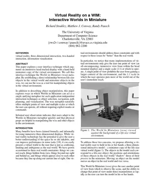
Virtual Reality on a WIM: Interactive Worlds in Miniature Richard Stoakley, Matthew J. Conway, Randy PauschThe University of VirginiaDepartment of Computer ScienceCharlottesville, V A 22903{rws2v | conway | pausch}@(804) 982-2200KEYWORDSvirtual reality, three-dimensional interaction, two-handed interaction, information visualizationABSTRACTThis paper explores a user interface technique which aug-ments an immersive head tracked display with a hand-held miniature copy of the virtual environment. We call this interface technique the Worlds in Miniature (WIM) meta-phor. By establishing a direct relationship between life-size objects in the virtual world and miniature objects in the WIM, we can use the WIM as a tool for manipulating objects in the virtual environment.In addition to describing object manipulation, this paper explores ways in which Worlds in Miniature can act as a single unifying metaphor for such application independent interaction techniques as object selection, navigation, path planning, and visualization. The WIM metaphor naturally offers multiple points of view and multiple scales at which the user can operate, all without requiring explicit modes or commands.Informal user observation indicates that users adapt to the Worlds in Miniature metaphor quickly and that physical props are helpful in manipulating the WIM and other objects in the environment.INTRODUCTIONMany benefits have been claimed formally and informally for using immersive three dimensional displays. While vir-tual reality technology has the potential to give the user a better understanding of the space he or she inhabits, and can improve performance in some tasks [18], it can easily present a virtual world to the user that is just as confusing, limiting and ambiguous as the real world. We have grown accustomed to these real world constraints: things we can-not reach, things hidden from view, things beyond our sight and behind us, and things which appear close to each other because they line up along our current line of sight. Our vir-tual environments should address these constraints and with respect to these issues be “better” than the real world.In particular, we notice that many implementations of vir-tual environments only give the user one point of view (an all-encompassing, immersive view from within the head mounted display) and a single scale (1:1) at which to oper-ate. A single point of view prohibits the user from gaining a larger context of the environment, and the 1:1 scale in which the user operates puts most of the world out of the user’s immediate reach.To address these two concerns, we propose allowing a vir-tual reality user to hold in his or her hands a three-dimen-sional interactive model – a miniature copy of the life-size virtual world (figure 1). The objects in the model each cor-respond to a life-size object; the positions and orientations of these objects in the real world “shadow” those of their proxies in the miniature. Moving an object on the model moves an object in the real world and vice versa.This World In Miniature (WIM) gives the user another point of view from which to observe the scene, and the ability to change that point of view under direct manipulation as rap-idly as the user can turn the model in his or her hands.As an adjunct to the WIM, we have explored the advantages and disadvantages of grounding the user’s perception of the model with a physical prop; in this case, a clipboard.The rest of this paper discusses previous work in the realm of miniature worlds used for three dimensional interfaces, a description of our WIM implementation, the basic interac-tion techniques we have used to demonstrate the effective-ness of the WIM concept, and the importance of asymmetric two-handed interaction. We conclude with results from informal user observation of the WIM interface and a dis-cussion of future work.PREVIOUS WORKMany researchers have dealt with the open questions of three dimensional object manipulation and navigation in virtual environments. The World in Miniature metaphor draws on these previous experiences, and attempts to syn-thesize an intuitive, coherent model to help address these questions. Most previous work falls into two categories: (1) object manipulation and (2) navigation in virtual environ-ments.We use the term “navigation” to mean allowing the user to move in his or her virtual environment and helping the user maintain orientation while there.Previous Work in Object ManipulationWare’s Bat [23] interface demonstrates the use of a 6 degree-of-freedom (DOF) input device (a position and ori-entation tracker) to grab and place objects in a virtual envi-ronment. In this work, Ware used the bat to pick up and manipulate the virtual objects themselves, not miniature, proxy objects. Ware found that users easily understood the 1:1 mapping between translations and rotations on the input device and the object being manipulated. This study was a unimanual task and did not place the user’s hands in the same physical space as the graphics.In Sachs’s 3-Draw [20], we see two hands used asymmetri-cally in a three-dimensional drawing and designing task. In addition to this, Sachs used props for each of the user’s hands and found that relative motion between hands was better than a fixed single object and one free mover. 3-Draw was not implemented in an immersive, head-tracked envi-ronment and the system did not provide multiple, simulta-neous views. The input props controlled the point of view by rotating the object’s base plane.Hinkley’s [13] work with props exploited the asymmetric use of hands, which follows from work by Guiard [12]. This work showed how a prop in the non-dominant hand can be used to specify a coordinate system with gross ori-entation, while the user’s preferred hand can be used for fine grain positioning relative to that coordinate system. This work is also three dimensional but non-immersive and directly manipulates an object at 1:1 scale in a “fishtank”paradigm.3DM [2] was an immersive three dimensional drawing package, but provided only one point of view at a time and required the user to change scale or fly explicitly to manip-ulate objects which were currently out of arm’s reach. But-terworth states that users sometimes found the scaling disorienting.Schmandt’s [21] early explorations of Augmented Reality (AR) used a half-silvered mirror over a stationary drafting tablet in order to specify both a base plane and a slicing plane in computer generated VLSI models. He found this surface invaluable in constraining the user’s input to a plane. The scene was not immersive and the system only displayed one scale view at a time.Previous Work in NavigationDarken’s [7] discussion of navigating virtual environments enumerates many important techniques and compares their relative strengths and weaknesses. Several of the naviga-tion techniques presented were WIM-like maps, but were primarily two-dimensional in nature. Through the WIM interface, some of these techniques have been extended into the third dimension.Ware [24] explored the possibilities of holding the three-dimensional scene in hand for the purpose of quickly navi-gating the space. He found this scene in hand metaphor par-ticularly good for quickly viewing the bounding-cube edges of a scene. The scene in hand task was a unimanual opera-tion which employed ratcheting to perform large rotations. The work most closely resembling the WIM interface was Fisher’s map cube in virtual reality [9]. The NASA VIEW system used a three dimensional miniature map of the immersive world to help navigate. In addition, it used mul-tiple two dimensional viewports to jump from one place in the virtual environment to another. A user’s manipulation of the “map cube” was unimanual. A similar map-cube concept was referred to as the God’s-eye-view in the super cockpit project [11].Previous Work in Object SelectionMany researchers have explored methods for selecting objects in a virtual world. Common approaches include raycasting [10] [23] and selection cones [15]. Both of these techniques suffer from object occlusion and therefore need to be tied closely with some mechanism that can quickly establish different points of view.Put-That-There [3] used selection via a combination of pointing and naming (or description). Pointing in this two dimensional application is analogous to raycasting in vir-tual environments.SYSTEM DESCRIPTIONTo explore the benefits and limitations of the WIM meta-phor, we built a simple three dimensional modeling pack-age that could be used as a design tool for a traditional architecture design project called a Kit of Parts.We outfitted the user’s non-dominant hand with a clipboard attached to a Polhemus position sensor. In his or her other hand, the user holds a tennis ball in which we have installedtwo buttons and another Polhemus™ sensor. This button-ball was used as the selection and manipulation tool for all of our user observation and WIM development. The first button on the buttonball was used for selection of objects,and the second was left open for application-specified actions. Thus equipped, the user’s view from inside the HMD is exactly like that in any other immersive virtual environment, except that the user can raise the clipboard to view a miniature copy of the world in which he or she is standing and can lower the WIM graphics out of sight toremove them from his or her field of view (figure 2).The WIMgraphics attached to the clipboard are nothing more than a miniature copy of all the surrounding graphics in the immersive environment. Each of the objects in the WIM copy are tied to their counterparts in the immersive environment through pointers and vice versa at the point of WIM creation. In this way, when an object responds to a method call, the object has enough information to ensure that the same method gets called on its “shadow” object.Thus the user can manipulate the objects in the WIM and the objects in the world will follow (video figure 1 - The WIM Interface). The environment itself (in miniature)becomes its own widget for manipulating objects in the environment [5].Software and EquipmentThe Kit of Parts modeler was implemented using the Alice Rapid Prototyping System [6] running the simulation on a Sun Microsystems Sparc 10™ and rendering on a Silicon Graphics Onyx Reality Engine 2™. Typical rendering rates were about 25 frames per second (FPS ), while simulation rates were typically 6FPS . A Virtual Research Flight Hel-met™ was used for the display and was tracked with a Pol-hemus Isotrak magnetic tracker. The buttonball and clipboard each carried a Polhemus tracker sensor for posi-tion and orientation information.INTERACTION TECHNIQUES USING THE WIMIn this section, we discuss basic application independent WIM -based interaction techniques we have built using the Alice Rapid Prototyping System [6].Quickly Changing the POVBeing able to see objects from many different angles allows us to quickly remove or reduce occlusion and improves the sense of the three-dimensional space it occupies [22].Because the WIM is a hand-held model, the user can quickly establish different points of view by rotating the WIM in both hands. Note that this form of “WIM fly-by” can often give the user all the information that he or she needs with-out destroying the point of view established in the larger,immersive point of view. We believe that this interaction technique can establish a new viewpoint more quickly and with less cognitive burden than a technique that requires an explicit “flight” command and management of the flight path.Object Selection: Overcoming Range and OcclusionIf the virtual, immersive environment is very large, there will be objects that are out of physical arm’s reach. If the user must touch an object to select it, the user would have to employ a separate flying mechanism, which means mov-ing the camera; a sometimes disorienting or otherwise inap-propriate approach. Armed with a World In Miniature ,the user now has the choice of selecting objects either by point-ing to the object itself (as before) or by pointing to its proxy on the WIM . By turning the model in his or her hands, the user can even view and pick objects that are obscured by his or her current line of sight from the immersive camera viewpoint. The WIM provides a second (often “bird’s eye”)point of view from which to examine the scene.Object ManipulationOnce objects are selected, the WIM allows us to manipulate those objects at either the scale offered by the WIM or the one-to-one scale offered by the immersive environment. If the scale of the WIM is smaller than that of the immersive world, manipulating objects on the WIM necessarily gives the user far-reaching coarse-grained control of objects.The WIM can also display objects at a greater than one-to-one scale, implementing a three dimensional magnifying glass of sorts. This gives the user very fine grain control of objects through the WIM at the expense of range. Though we have not implemented zooming in our current system,we clearly see the need for allowing the user to get more detail on the WIM or to zoom out to view more context. We are currently pursuing this avenue of research.We speculate that because the WIM is clearly a model attached to the user’s hand, it is seen as something separate from the rest of the immersive environment. The WIM therefore naturally offers two different scales to the user without requiring explicit modes or commands.An Example: Hanging a PicturePutting these ideas together, we can consider an example task: hanging a picture on a wall. This task is typical of abroad class of two-person tasks in which the proximity required to manipulate an object interferes with the desire to see those effects in a larger context. With a WIM, a single user can stand at a comfortable distance to view the picture in context, while at the same time reaching into the WIM to manipulate it.Of course, the user could choose to use the WIM the other way around: fly close to the wall to stand next to the pic-ture, then use the WIM to view the entire room in miniature to determine if the picture is straight. Examining relative strengths and weaknesses of each of these approaches is an area of further study.Mixing Scales and OperationsViewing, selection, and manipulation are independent oper-ations. Because the WIM gives the user another scale at which to operate, the user can choose the most appropriate scale for any given subtask, and even switch scales in the middle to suit the requirements of the task. For example: the user can reach into the WIM to select a distant object (taking advantage of the greater than 1:1 scale of the WIM), and then reach out to the immersive world to move the WIM-selected object at a distance in 1:1: scale [23] [15] all the while viewing the scene in the WIM.RotationOur current implementation allows users to rotate objects, through ratcheting (repeated grabbing, rotating and releas-ing) [25] and is therefore more awkward than a rotation done with just the fingers [15]. Interestingly, some users found it just as effective to grab the object and to counter-rotate the entire WIM.In our current implementation, rotation is gridded to 30 degree increments, primarily to assist in aligning rectilinear objects [15]. We found that if the rotation grid is too course (greater than about 45 degrees), some people assume that they cannot rotate at all and if set to 15 degrees or less, users report that rotation behaves as if it had no gridded increments at all.Navigation: Flight with a WIMTo make the view travel through the immersive environ-ment, the most common user interface technique in virtual environments is probably “flying.” If the WIM includes some representation of the user as an object in the scene, the user can simply reach into the WIM and “pick himself up” to change his location in the environment. This raises the question of when to update the immersive world as objects in the WIM are manipulated. We enumerate three possibilities.Updating after Manipulation:immediate / post-mortem / batchWhen changes are made on the WIM, we usually move the real object and the proxy object simultaneously, something we refer to as immediate update. Under some conditions, immediate update is either not desirable (due to visual clut-ter or occlusion) or impossible (the complexity of the object prevents changes to it from being updated in real time). In these situations, we use post-mortem update,where the immersive environment updates only after the user is finished with the WIM interaction and has released the proxy.A good special case of post-mortem update is the case of moving the user’s viewpoint. We find that immediate update of the camera while the user is manipulating the camera proxy is highly disorienting, so instead we wait until the user has stopped moving the camera, and then use a smooth slow in / slow out animation [16] to move the camera to its new position. This animated movement helps maintain visual continuity [15].Another useful form of update delay is batch update. Here, the user makes several changes to the WIM and then issues an explicit command (e.g. pressing the second button on the buttonball) to cause the immersive environment to com-mit to the current layout of the WIM. This is useful for two reasons. First, before the user commits his or her changes, the user has two independent views of the environment (the “as-is” picture in the immersive world and the “proposed”picture in the WIM). Secondly, it might be the case that moving one object at a time might leave the simulation in an inconsistent state, and so “batching” the changes like this gives the user a transaction-like commit operation on the changes to objects in the scene (with the possibility of supporting rollback or revert operations if the changes seem undesirable halfway through the operation). VISUALIZATIONThe Worlds in Miniature metaphor supports several kinds of displays and interaction techniques that fall loosely under the heading of visualization. These techniques exploit the WIM’s ability to provide a different view of the immersive data with improved context. It would seem that the WIM is good for visualization for all the same reasons that a map is good for visualization:Spatially locating and orienting the user:the WIM can pro-vide an indicator showing where the user is and which way he or she is facing relative to the rest of the environment. Path planning: with a WIM we can easily plan a future camera path in three dimensions to prepare for an object fly-by. The user can even preview the camera motion before committing him or herself to the change in the larger, immersive viewpoint.History: if the user leaves a trail behind as he or she travels from place to place, the WIM can be used like a regular 2D map to see the trail in its entirety. Dropping a trail of crumbs is not as useful if you cannot see the trail in context. Measuring distances:the WIM can be configured to display distances between distant (or very closely spaced) points that are difficult to reach at the immersive one-to-one scale. The WIM also provides a convenient tool for measuring areas and volumes.Viewing alternate representations:the immersive environ-ment may be dense with spatially co-located data (i.e. topo-logical contours, ore deposits, fault lines). The user candisplay data like this on the WIM, showing an alternate view of the immersive space in context. The improved context can also facilitate the observation of more implicit relation-ships in a space (i.e. symmetry, primary axis) and can dis-play data not shown in the immersive scene (circulation patterns, wiring and plumbing paths). Here, the WIM acts more like a three dimensional version of Beir’s “magic lenses” [1] or one of Fitzmaurice’s “active maps” [10]. Three Dimensional Design: the WIM, being a small three dimensional model, serves the same functions that architec-tural models have traditionally served.MULTIPLE WIMSUntil now, we have considered only a single instantiation of a WIM in a virtual environment, but clearly there might be a reason to have more than one such miniature active at a time. Multiple WIM s could be used to display:•widely separated regions of the same environment •several completely different environments•worlds at different scales•the same world displayed at different points in time This last option allows the user to do a side by side compar-ison of several design ideas (video figure 2 –Multiple WIM s). A logical extension of this notion is that these snap-shots can act as jump points to different spaces or times, much the same way hypertext systems sometimes have thumbnail pictures of previously visited documents [14]. Selecting a WIM would cause the immersive environment to change to that particular world [9].Multiple WIM s enable users to multiplex their attention much the same way Window Managers allow this in 2D. These multiple views into the virtual world, allow the user to visually compare different scales and/or different loca-tions [8].MANIPULATING THE WIMThrough the exploration of the previous interfaces, several issues arose concerning the interface between the human and the WIM tool.The Importance of PropsOne of our early implementations of the WIM work did not use physical props; the user grasped at the WIM graphics as he or she would any other graphical object in the scene. As long the user continued the grasping gesture, the WIM fol-lowed the position and orientation of the user’s hand and when released, it would remain hovering in space wherever it was dropped. While this was sufficient for many tasks, we found that rotating the WIM without the benefit of haptic feedback was extremely difficult. Invariably, users would contort themselves into uncomfortable positions rather than let go of the WIM to grab it again by another, more comfort-able corner.After Sachs [20], we decided to use physical props to assist the user’s manipulation of the WIM itself. To represent the WIM, we chose an ordinary clipboard to which we attached a Polhemus 6 DOF tracker for the user’s non-dominant hand. For the user’s preferred hand, we used a tennis ball with a Polhemus tracker and two buttons (figure 3). Props: The ClipboardThis prop allows the user to rotate the WIM using a two-handed technique that passes the clipboard quickly from one hand to the other and back when the rotation of the WIM is greater than can be done comfortably with one hand. Interestingly, some users hold the clipboard from under-neath, rotating the clipboard deftly with one hand. Both of these techniques are hard to imagine doing in the absence of haptic feedback provided by a physical prop.Props: The ButtonballBefore we settled on the buttonball as our primary pointing device, we experimented with a pen interface to the WIM. This technique is most appropriate for manipulation of objects when they are constrained to a plane [21] (the base plane being the default). When manipulation of objects in three dimensions is called for, a pen on the surface of the clipboard does not appear to be expressive enough to cap-ture object rotation well.Two Handed InteractionOur implementation of the WIM metaphor takes advantage of several previously published results in the field of motor behavior that have not been fully exploited in a head tracked virtual environment. The most important of these results state that a human’s dominant (preferred) hand makes its motions relative to the coordinate system speci-fied by the non-dominant hand, and the preferred hand’s motion is generally at a finer grain [12]. In our case, the non-dominant hand establishes a coordinate system with the clipboard and the dominant hand performs fine grained picking and manipulation operations.While the dominant hand may be occupied with a pointing device of some kind, it is still sufficiently free to help the other hand spin the WIMquickly when necessary.Shape of PropsLike all real world artifacts, the shape of the props and the users’ experience suggest things about the usage of the props [17]. For example, the shape of the clipboard says something to users about its preferred orientation. The cur-sor’s physical prop is spherical, indicating that it has no preferred orientation, and in fact it does not matter how the cursor is wielded since rotation is relative to the plane spec-ified with the non-dominant hand, which holds the clip-board.The clipboard also provides a surface that the user can bear down on when necessary. This is similar to the way an artist might rest his or her hand on a paint palette or a guitarist might rest a finger on the guitar body.PROBLEMS WITH PHYSICAL PROPSThe use of the clipboard as a prop presents some problems of its own.FatigueHolding a physical clipboard, even a relatively light one, can cause users to fatigue rather quickly. To overcome this problem, we created a simple clutching mechanism that allows the user to alternately attach and detach the WIM from the physical prop with the press of a button. When detached, the WIM “floats” in the air, permitting the user to set the prop down (video figure 3 – Prop Clutching). This clutching mechanism extended well to multiple WIM s: when the user toggles the clutch, the closest WIM snaps to the user’s clipboard. Toggling the clutch again disengages the current WIM and allows the user to pick up another WIM. Another technique for relieving arm stress is to have the user sit at a physical table on which the clipboard could be set. Users can also rest their arms on the table while manip-ulating the model. The presence of the table clearly pre-sents a mobility problem for the user because it prevents the user from moving or walking in the virtual environ-ment, and so may not be ideal for all applications. Limitations of Solid ObjectsIn our experience, one of the first things a user of the WIM is likely to try is to hold the WIM close to his or her face in order to get a closer, more dynamic look at the world. Users quickly discover that this is an easy, efficient way to estab-lish many different points of view from inside the minia-ture. Unfortunately, many times the physical prop itself gets in the way, preventing the user from putting the tracker in the appropriate position to get a useful viewpoint. Fortu-nately, the ability to disengage the WIM, leaving it in space without the clipboard helps alleviate this problem. INFORMAL OBSERVATIONWe observed ten people using the WIM. Some had previous experience with virtually reality, and some had three dimensional design experience (e.g. architecture students). Users were given a simple architectural modeler and asked to design an office space. We proceeded with a rapid “observe, evaluate, revise” methodology to learn about the Worlds in Miniature interface.The user was given a miniature copy of the room he or she was standing in, and a series of common furniture pieces on a shelf at the side of the WIM (figure 4). The user was then asked to design an office space by positioning the furniture in the room.In many ways, this design task replicates the traditional architectural design project known as a Kit of Parts. The furniture pieces (half-height walls, shelves, tables and table corner pieces) represent the kit of manipulable objects. Moving the traditional kit of parts project into virtual real-ity was particularly appealing for several reasons:•It constrains the space in which the user can work.•Since users are designing a life-size space, clearly see-ing that space at 1:1 scale is helpful.•The WIM succinctly replaces the plans, elevations and models typically associated with this type of design project.The WIM that we used was a 1/4” scale version of the immersive world, with a snap spacing of 1/8” (0.5 scale feet). In addition to the translation snap, rotation was con-strained to be about the Z axis in increments of 30 degrees.User ReactionsWe observed users in order to see how viable a solution the WIM interface was to several types of tasks. While it was not our intention for the study to produce concrete num-bers, we were after what Brooks refers to as interesting “Observations” [14]. We hoped to gain some sense of:1 )How quickly do users take to the WIM metaphor?2 )How do users like the weight and maneuverability ofthe physical clipboard?3 )Do users like clutching? Do they take to it easily?4 )How do users feel about moving themselves via thecamera proxy?None of the users expressed problems establishing the map-。

Abstract的用法1. 什么是Abstract在计算机科学领域,Abstract(抽象)是一种编程概念,用于描述一种将问题或现实世界中的实体抽象化的方法。
通过抽象,我们可以将复杂的问题简化为更易于理解和处理的形式。
抽象的关键是忽略不必要的细节,只关注最重要的方面。
在软件开发中,抽象是一种重要的设计原则,它可以帮助开发人员构建模块化、可扩展和易于维护的代码。
2. 抽象的作用抽象的作用在于隐藏细节,只暴露必要的接口和功能。
通过抽象,我们可以将复杂的系统分解为更小的模块,并将这些模块组合在一起以实现更大的功能。
抽象可以提高代码的可读性和可维护性,并降低代码的复杂性。
它还可以促进代码的重用,因为抽象可以将通用的功能封装为可复用的组件。
3. 抽象的实现方式在编程中,抽象可以通过多种方式来实现。
下面是几种常见的抽象实现方式:3.1 抽象类抽象类是一种特殊的类,它不能被实例化,只能被继承。
抽象类可以包含抽象方法和具体方法。
抽象方法是没有实现的方法,需要子类根据自己的需求来实现。
抽象类可以用作其他类的基类,通过继承抽象类,子类可以获得抽象类的方法和属性。
public abstract class Animal {public abstract void makeSound();public void sleep() {System.out.println("Zzz");}}3.2 接口接口是一种定义了一组方法的抽象类型。
接口可以被类实现,一个类可以实现多个接口。
接口中的方法都是抽象的,没有实现。
通过实现接口,类可以获得接口中定义的方法,并根据自己的需求来实现这些方法。
public interface Shape {double getArea();double getPerimeter();}3.3 泛型泛型是一种参数化类型的机制,它可以使代码更加通用和灵活。
通过使用泛型,我们可以编写与特定类型无关的代码,提高代码的重用性。
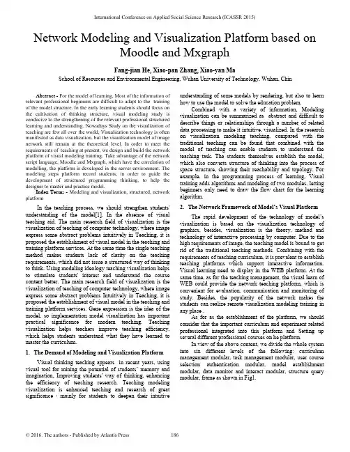
Network Modeling and Visualization Platform based onMoodle and MxgraphFang-jian He, Xiao-pan Zhang, Xiao-yan MaSchool of Resources and Environmental Engineering, Wuhan University of Technology, Wuhan, ChinAbstract - For the model of learning, Most of the information of relevant professional beginners are difficult to adapt to the training of the model structure. In the early learning students should focus on the cultivation of thinking structure, visual modeling study is conducive to the strengthening of the relevant professional structured learning and understanding. Nowadays Study on the visualization of teaching are few all over the world, Visualization technology is often manifested as data visualization, but the visualization model of image network still remain at the theoretical level. In order to meet the requirements of teaching at present, we design and build the network platform of visual modeling training. Take advantage of the network script language, Moodle and Mxgraph, which have the correlation of modelling, the platform is developed in the server environment. The modeling steps platform record students, in order to guide the development of structured programming thinking, to help the designer to master and practice model.Index Terms - Modeling and visualization, structured, network platformIn the teaching process, we should strengthen students' understanding of the model[1]. In the absence of visual teaching aid. The main research field of visualization is the visualization of teaching of computer technology, where image express some abstract problems intuitively in Teaching, it is proposed the establishment of visual model in the teaching and training platform services. At the same time the single teaching method makes students lack of clarity on the teaching requirements, which did not issue a structured way of thinking to think. Using modeling ideology teaching visualization helps to stimulate students' interest and understand the course content better. The main research field of visualization is the visualization of teaching of computer technology, where image express some abstract problems Intuitively in Teaching, it is proposed the establishment of visual model in the teaching and training platform services. Gene expression is the idea of the model, so implementation model visualization has important practical significance for modern teaching. Teaching visualization helps teachers improve teaching efficiency, which helps students understand what they have learned to master the curriculum.1.The Demand of Modeling and Visualization PlatformVisual thinking teaching appears in recent years, using visual tool for mining the potential of students’memory and imagination, Improving students' way of thinking, enhancing the efficiency of teaching research. Teaching modeling visualization is enhanced teaching and research of great significance,mainly for students to deepen their intuitive understanding of some models by rendering, but also to learn how to use the model to solve the education problem.Combined with a variety of information, Modeling visualization can be summarized as abstract and difficult to describe things or relationships through a number of related data processing to make it intuitive, visualized. In the research on visualization modeling teaching, compared with the traditional teaching can be found that combined with the model of teaching can enable students to understand the teaching task. The students themselves establish the model, which also converts structure of thinking into the process of space structure, showing their reachability and topology. For example, in the programming process of learning, Visual training adds algorithms and modeling of two modules, letting beginners only need to draw the flow chart for the learning algorithm.2.The Network Framework of Model’s Visual PlatformThe rapid development of the technology of model’s visualization is based on the visualization technology of graphics, besides, visualization is the theory, method and technology of interactive processing by computer. Due to the high requirements of image, the teaching model is bound to get rid of the traditional teaching methods. Combining with the requirements of teaching curriculum, it is prevalent to establish teaching platforms which support interactive information. Visual learning need to display in the WEB platform. At the same time, as for the teaching management, the visual learn of WEB could provide the network teaching platform, which is convenient for evaluation, communication and monitoring of study. Besides, the popularity of the network makes the students can realize remote visualization modeling training in any place .As for as the establishment of the platform, we should consider that the important curriculum and experiment related professional integrated into this platform and Setting up several different professional courses on he platform.In view of the above content, we divide the whole system into six different levels of the following: curriculum management modular, task management modular, user course selection authentication modular, model establishment modular, data monitor and interact modular, structure query modular, frame as shown in Fig1.International Conference on Applied Social Science Research (ICASSR 2015)Fig.2. Platform Framework3. Establishment of Plantform EnvironmentA. Model Selection of Platform SoftwareWe usually use two software which responsible for teaching communicate platf orm’s establishment and the model of the plug-in support. It provides a data view at the time of containing the actual data. In JGraph products, Mxgraph is a graphical component which provides interface with web integrated. The client requires a Web server to provide the required documents, it can also run on the local file system. The background can be used to support the integrated of existing server language, so it is very friendly to the development.In consideration of the analysis of the component of model, the platform must also meet the course assignments, including task management modular and data monitor and interact modular. At the same time, the development of language of model plug-in and learning platform need to keep compatibility, so finally we select the current market popular teaching platform software Moodle to meet the needs of establishment of WEB visual modeling and learning platform. B. Moodle Learning Platformand Mxgraph Graphical TrainingMoodle[3] is an open-source Course Management System (CMS), also known as the Learning Management System (LMS) or Virtual Learning Environment (VLE), which has simple and elegant interface, so users can adjust interface and content according to the requirement at any time. The Moodle platform is a dynamic website program by the PHP scripting language, it is configured of the MySQL database supported by PHP, and it could be used to storage the data and file generated by the Moodle interface.The creation of graphics is by Mxgraph, which includes all the web[2] development language. Mxgraph client is a graphical component,and it can provide a interface of web integrated. Mxgraph has the architecture and graphics components of MVC, which has the same rules of JGraphthe, and it can be applied in a number of development. The clientcan realize localized operation, also is convenient to users to develop project alone.4. The Key Technology of Visualization Platform In the visual modeling training platform development process, the internal structure of the Moodle must be carried out to understand the, including the database and the module of data link. For example, the user who select the corresponding courses in the Moodle will enter into the corresponding modeling interface, and the operation is fed back to the establishment of the database, which also marks the link between two software. To achieve the overall visual programming training platform, it must be associated with Mxgraph and Moodle. Relationship in the user operation with reference to FIG. 2.Fig.2. flow chart of software operation platformA. Graphical Development Training Page in the MxgraphIn the Mxgraph, The menu bar and feature-rich tool make creating and editing simple graphics. However, the official demo given too much to call back url and Java code, it’s not easy to develop in the front page to connect Moodle. Written by JavaScript and built in the Tomcat server environment. The development of requirements is to refer to the corresponding component, the front page of the project Mxgraph should be met:1) Drag the icon to create a user model. There are mobile location, modify the size of the function.2) The above steps can be recorded in real time by the back-end database records. For the above requirements, the project on the local server for Mxgraph develop new homepage.In response to these requirements, the extraction of the core code of internal mxClient. Js can create a model. Then, Simple graphical configuration pull function that meets the basic requirements. To create a model of the type, according tothe different needs of different courses, it can be added in the model gallery.B.Monitoring Training Records by MoodleMoodle course modules not only provide support, this project requires the user has a monitoring operation on, that is user real-time monitoring and recording procedures. Monitoring records shall be, user adds a type of block diagram, or the user modifies a block diagram. User visualization and modeling in Mxgraph interface has been developed, in order for managers to understand their structure and thinking to create.With JavaScript, we can reconstruct the entire Mxgraph client to add some function, including adding, removing, changing or rearranging items on the page. When we want to change any module on the page. JavaScript needs access to the entrance of all the elements in the HTML document, which entrance along with the methods and properties to add, move, change or remove the HTML element, Is obtained through the document object model(DOM).C.Structure Analysis of Moodle and Mxgraph and theirInteractionThe first two has completed the creation of the Mxgraph model and the operation of the user record creation process. Then We need to establish the model to transfer to Moodle. And the database recording operation is also uploaded to the result. So what we need to achieve is data exchange between Mxgraph and Moodle. But the data in the Moodle will display where the front in the corresponding position has becoming the key of the platform’s development.The specific steps are provided by the user clicks on the link after elective operation. Table assign submission in the corresponding Mysql in the formation generate the corresponding value. Then the results of MVC model corresponding to the records generate in the online text field in the assign submission online text. At the same time, IP, time to submit homework and so on will be recorded. This text will be submitted in the Moodle view display operation.The technical scheme is able to complete the relationship and coordination between the two software, presents a complete WEB visualization programming training platform in the server set up after the completion.5.Moodle Operation Modular ManagementEasy to operate, to complete the development of the technology of Moodle and Mxgraph after the details of the treatment in the actual operation, the front end service platform forms a teaching system.Managers can create courses in Moodle, and publish the work that can be placed in the Mxgraph link. The information can be accepted by the users who select corresponding course. After the user selection in the MySQL assign submission database automatically appear in a record, recording the submission user ID and field operation number corresponding to the submission field in assign submission online text with the serial number. Finally, managers can give the score in the submitted after the operation. The score will be saved in the assign grades data sheet.So far, all the function modules of experimental teaching platform of visual modeling is the development and application. It is not only support the modeling of all kinds of teaching model, but also set up the framework of the platform of information processing, which is used for the analysis of the job submission. Managers judge from the record whether the user can independently accomplish the work directly or theft. It can be in the operation record inquiry knowing, which exceeds the completeness of traditional teaching that can have in the practical application.6.SummaryThe visualization platform for educational institutions or small laboratory provides a practical digital teaching, scientific research, management and service network platform. In addition, through the realization of the environment (including equipment, etc.), resources to the application (including teaching, learning, management, service and office), it construct a digital space based on the traditional campus. In the dimension of time and space to expand the real campus the traditional campus, the platform finally realizes the educational process information, so as to improve the management level and efficiency of the aim of education. AcknowledgmentsThe authors gratefully acknowledge financial support from the Practices Education System Improvement Project of Wuhan University of Technology.References[1]Zhiyuan Yuan, Xinqi Zheng, Lina Lv et al.. From design to digital model:A quantitative analysis approach to Garden Cities theory. EcologicalModelling, 2014, 289.[2]Kartik Kandadai Agaram. Prefetch mechanisms by application memoryaccess pattern. The University of Texas at Austin, 2007.[3]Zoran Vručinić,Aleksandar Janković,Milan Miladinovićet al..EVALUATION OF CLINICAL DIAGNOSIS WITH “STORE AND FORWARD”TELEDERMATOLOGY. Acta Medica Medianae, 2010, 49(4).[4]Chris Brunsdon, Lex Comber. Assessing the changing flowering date ofthe common lilac in North America: a random coefficient model approach. GeoInformatica, 2012, 16(4).[5]Qian Liu. Securing telehealth applications in a Web-based e-Healthportal. Concordia University (Canada), 2008.。
英语作文-虚拟现实技术应用于文化创意产业,打造沉浸式体验Virtual Reality Technology Applied to Cultural and Creative Industries: Creating Immersive Experiences。
Introduction:In recent years, virtual reality (VR) technology has gained significant attention andhas been applied to various industries, including gaming, education, healthcare, and entertainment. One industry that can greatly benefit from VR is the cultural and creative industries. This article explores the potential of VR technology in the cultural andcreative industries and how it can be used to create immersive experiences for users.1. Enhancing Cultural Heritage Preservation:Virtual reality provides a unique opportunity to preserve and showcase cultural heritage in a way that traditional methods cannot. By creating virtual replicas of historical sites, artifacts, and artworks, VR allows users to explore and interact with them as if they were physically present. This not only helps in preserving cultural heritage but also provides a more engaging and immersive experience for visitors.2. Enriching Museum and Gallery Experiences:VR technology can revolutionize the way people visit museums and galleries.Instead of merely observing artworks or artifacts behind glass, visitors can now step into virtual exhibitions and experience them in a whole new way. Through VR headsets, users can walk through virtual galleries, view artworks up close, and even interact with them.This not only enhances the visitor experience but also opens up new possibilities for curators and artists to present their works.3. Transforming Performing Arts:Virtual reality has the potential to transform the performing arts industry by breaking the barriers of time and space. With VR, users can attend live performances or concerts from anywhere in the world, as if they were sitting in the front row. Additionally, VR can also create unique and immersive experiences by blending virtual elements with live performances. This fusion of technology and art opens up endless possibilities for creative expression.4. Revolutionizing Film and Entertainment:VR technology has already made significant strides in the entertainment industry, with the emergence of VR films and experiences. By wearing VR headsets, users can become part of the story, immersing themselves in the virtual world and interacting with the characters and environment. This not only enhances the entertainment value but also offers new storytelling techniques and perspectives for filmmakers.5. Fostering Collaborative Creativity:VR technology can also facilitate collaborative creativity within the cultural and creative industries. Artists and designers can use VR tools to work together in virtual spaces, regardless of their physical locations. This enables seamless collaboration, idea sharing, and real-time feedback, ultimately leading to more innovative and immersive creations.Conclusion:Virtual reality technology has the potential to revolutionize the cultural and creative industries by creating immersive experiences for users. From enhancing cultural heritage preservation to transforming performing arts and revolutionizing film and entertainment, VR opens up new possibilities for creativity and engagement. As the technology continues to advance, it is crucial for stakeholders in the cultural and creative industries to embrace VR and explore its full potential in order to stay at the forefront of innovation.。
2021⁃03⁃10计算机应用,Journal of Computer Applications 2021,41(3):839-844ISSN 1001⁃9081CODEN JYIIDU http ://基于双相机捕获面部表情及人体姿态生成三维虚拟人动画刘洁,李毅*,朱江平(四川大学计算机学院,成都610065)(∗通信作者电子邮箱liyi_ws@ )摘要:为了生成表情丰富、动作流畅的三维虚拟人动画,提出了一种基于双相机同步捕获面部表情及人体姿态生成三维虚拟人动画的方法。
首先,采用传输控制协议(TCP )网络时间戳方法实现双相机时间同步,采用张正友标定法实现双相机空间同步。
然后,利用双相机分别采集面部表情和人体姿态。
采集面部表情时,提取图像的2D 特征点,利用这些2D 特征点回归计算得到面部行为编码系统(FACS )面部行为单元,为实现表情动画做准备;以标准头部3D 坐标值为基准,根据相机内参,采用高效n 点投影(EP n P )算法实现头部姿态估计;之后将面部表情信息和头部姿态估计信息进行匹配。
采集人体姿态时,利用遮挡鲁棒姿势图(ORPM )方法计算人体姿态,输出每个骨骼点位置、旋转角度等数据。
最后,在虚幻引擎4(UE4)中使用建立的虚拟人体三维模型来展示数据驱动动画的效果。
实验结果表明,该方法能够同步捕获面部表情及人体姿态,而且在实验测试中的帧率达到20fps ,能实时生成自然真实的三维动画。
关键词:双相机;人体姿态;面部表情;虚拟人动画;同步捕获中图分类号:TP391.4文献标志码:A3D virtual human animation generation based on dual -camera capture of facialexpression and human poseLIU Jie ,LI Yi *,ZHU Jiangping(College of Computer Science ,Sichuan University ,Chengdu Sichuan 610065,China )Abstract:In order to generate a three -dimensional virtual human animation with rich expression and smooth movement ,a method for generating three -dimensional virtual human animation based on synchronous capture of facial expression andhuman pose with two cameras was proposed.Firstly ,the Transmission Control Protocol (TCP )network timestamp method was used to realize the time synchronization of the two cameras ,and the ZHANG Zhengyou ’s calibration method was used to realize the spatial synchronization of the two cameras.Then ,the two cameras were used to collect facial expressions and human poses respectively.When collecting facial expressions ,the 2D feature points of the image were extracted and theregression of these 2D points was used to calculate the Facial Action Coding System (FACS )facial action unit in order toprepare for the realization of expression animation.Based on the standard head 3D coordinate ,according to the camera internal parameters ,the Efficient Perspective -n -Point (EP n P )algorithm was used to realize the head pose estimation.After that ,the facial expression information was matched with the head pose estimation information.When collecting human poses ,the Occlusion -Robust Pose -Map (ORPM )method was used to calculate the human poses and output data such as the position and rotation angle of each bone point.Finally ,the established 3D virtual human model was used to show the effect of data -driven animation in the Unreal Engine 4(UE4).Experimental results show that this method can simultaneously capture facial expressions and human poses and has the frame rate reached 20fps in the experimental test ,so it can generate naturaland realistic three -dimensional animation in real time.Key words:dual -camera;human pose;facial expression;virtual human animation;synchronous capture0引言随着虚拟现实技术走进大众生活,人们对虚拟替身的获取手段及逼真程度都提出较高要求,希望能够通过低成本设备,在日常生活环境下获取替身,并应用于虚拟环境[1]。
虚拟现实技术英文毕业论文Title: Virtual Reality Technology: An Exploration of its Applications and PotentialAbstract:This research paper aims to explore the various applications and potential of virtual reality (VR) technology. With the rapid advancement of technology, VR has emerged as a revolutionary tool with wide-ranging applications across various industries. This paper will provide an overview of VR technology, its components, and working principle. Additionally, it will discuss its applications in areas such as healthcare, entertainment, education, and training. Furthermore, this paper will present the potential challenges and future prospects of VR technology. The analysis of these aspects will enable us to better understand the impact of VR technology and its potential to reshape our world.Introduction:Virtual reality (VR) technology has gained significant attention and popularity in recent years. VR involves the use of immersive digital environmentsthat mimic the real world or create entirely new experiences. It allows users to interact with these virtual environments in real time, enhancing their sensory experience and creating a sense of presence. This technology has evolved from being a niche tool to a mainstream medium and is now being utilized across various industries.Components and Working Principle of VR Technology:VR technology typically consists of three main components: a virtual environment, a user interface, and tracking systems. The virtual environment is created using computer graphics or a combination of real-world images and computer-generated elements. The user interface includes devices such as head-mounted displays (HMDs), handheld controllers, and data gloves, which enable users to navigate and interact with the virtual environment. Tracking systems are used to capture the user's movements and translate them into the virtual world, providing a seamless and immersive experience.Applications of VR Technology:1. Healthcare: VR technology is being applied in healthcare for purposes such as pain management,rehabilitation, and surgical training. It allows patients to be immersed in virtual environments that distract them from pain or provide therapeutic experiences. VR rehabilitation exercises can help patients recover from physical injuries or disabilities. Surgical training simulations enable surgeons to practice intricate procedures in a safe and controlled environment.2. Entertainment: VR has revolutionized the entertainment industry by providing immersive gaming experiences and virtual tours. VR gaming allows users to engage in interactive gameplay that transcends traditional screen-based formats. Virtual tours allow users to explore historical sites, travel destinations, and museums from the comfort of their homes.3. Education: VR technology is transforming the way education is delivered. It enables students to visualize complex concepts and immersive themselves in virtual environments that enhance learning. For example, students can explore historical events, visit ancient civilizations, or conduct scientific experiments virtually.4. Training: VR is being used for training purposes in industries such as aviation, military, andmanufacturing. It provides a safe and cost-effective way to simulate real-life scenarios and practice critical skills. For example, pilots can undergo flight simulations in virtual environments, soldiers can receive combat training, and technicians can practice complex procedures.Challenges and Future Prospects:Despite the numerous advantages of VR technology, it also faces challenges such as high costs, technical limitations, and potential health risks. The high cost of VR equipment, limited availability of content, and technical requirements pose barriers to widespread adoption. Additionally, some users may experience motion sickness or disorientation when using VR extensively.However, the future prospects of VR technology are promising. Advancements in hardware and software are making VR more affordable and accessible to a wider audience. The potential applications of VR in fields such as remote work, telemedicine, and social interactions are immense. As the technology continues to evolve, VR has the potential to become an integral part of our everyday lives.Conclusion:Virtual reality technology has the potential to revolutionize numerous industries and reshape the way we perceive and interact with the world. Its applications in healthcare, entertainment, education, and training are already making a significant impact. While there are challenges to overcome, such as cost and technical limitations, the future prospects of VR technology are bright. As the technology becomes more accessible and affordable, we can expect to witness its widespread adoption and integration into various aspects of our lives.。
第43卷 第6期 包 装 工 程2022年3月 PACKAGING ENGINEERING1收稿日期:2022-02-20基金项目:国家重点研发计划资助(2019YFF0301305)作者简介:胡勇(1981—),男,博士,副教授,主要研究方向为VR/AR 内容智能生成与交互设计。
通信作者:沈旭昆(1965—),男,博士,教授,主要研究方向为数字媒体/虚拟现实研究与设计。
胡勇ab ,何玉振ab ,熊梦涵ab ,沈旭昆ab(a.北京航空航天大学 新媒体艺术与设计学院b.北京航空航天大学 虚拟现实技术与系统国家重点实验室,北京 100191)摘要:目的 面向混合现实电子沙盘虚拟3D 对象,开展3D 交互性能与用户体验研究与评估,提出交互设计原则和设计建议。
方法 针对混合现实环境下双手可触范围外的虚拟对象“选择”任务开展交互设计研究,引入虚拟对象布局排列方式作为评估变量,在3种典型的虚拟对象布局情况下,分别进行手控光线、头动、眼动与手势协同的3种交互方式性能及用户体验对比研究。
通过设计原型实验系统,进行用户体验测试,实验数据分析与评估,验证交互设计原则,提出交互设计建议。
结论 实验结果显示眼动与捏合手势结合的手眼协同交互方式在时间、任务负荷及用户偏好方面都具有显著优势。
手控光线与手势协同交互的准确性最优,并且这一优势在任何一种布局方式中都有所体现。
建议混合现实环境下的“选择”任务交互设计要注重功用性、持续性和愉悦性原则,提出了降低“选择”任务交互的工作负荷与疲劳及增强新颖交互提升愉悦性的设计建议。
关键词:混合现实;3D 交互;交互设计;体验设计与评估中图分类号:TB472 文献标识码:A 文章编号:1001-3563(2022)06-0001-10 DOI :10.19554/ki.1001-3563.2022.06.001Hand-Eye Collaborative Interaction Design of Virtual Object inMixed Reality Sand TableHU Yong ab , HE Yu-zhen ab , XIONG Meng-han ab , SHEN Xu-kun ab(a.School of New Media Art and Design, Beihang Universityb. State Key Laboratory of Virtual Reality Technology and Systems, Beihang University, Beijing 100191, China) ABSTRACT: This paper studies the 3D interaction performance and user experience evaluation of the virtual 3D object in the mixed reality sand table, and puts forward interaction design principles and design suggestions. The interaction design is carried out for the "selection" task of virtual objects outside the touchable range of both hands in the mixed reality en-vironment. The layout mode of virtual objects is creatively introduced as an evaluation variable. And under the three typ-ical virtual object layouts, a comparative study on the performance and user experience of three interactive modes of hand-controlled light, head movement, eye movement and gesture coordination is carried out. Through the design of an experimental prototype system, user experience test, experimental data analysis and evaluation, we verify the principles of interactive design, and put forward interactive design suggestions. The experimental results show that the hand-eye col-laborative interaction mode combined with gaze and pinch gesture has significant advantages in time, task load and user preference. The accuracy of point and pinch interaction is the best in all the three layouts. It is suggested that the design of "selection" task interaction in the mixed reality environment should pay attention to the principles of functionality, conti-nuity and pleasure, and put forward some design suggestions to reduce the work load and fatigue of "selection" task in-teraction and adopt novel interaction to improve pleasure.KEY WORDS: mixed reality; 3D interaction; interaction design; user experience design and evaluation. All Rights Reserved.2 包装工程 2022年3月沙盘是地理信息的立体化展示工具,被广泛应用于军事指挥、城市规划、大型赛事活动等领域,然而传统实体沙盘已经逐渐难以满足复杂动态变化信息的呈现需求。
Interactive Visualization of Protein DynamicsHenk Huitema and Robert van LiereCenter for Mathematics and Computer Science,AmsterdamAbstractThe study of time dependent characteristics of proteins is impor-tant for gaining insight into many biological processes.However,visualizing protein dynamics by animating atom trajectories doesnot provide satisfactory results.When the trajectory is sampledwith large times steps,the impression of smooth motion will be de-stroyed due to the effects of temporal aliasing.Sampling with smalltime steps will result in the camouflage of interesting motions.In this case study,we discuss techniques for the interactive3Dvisualization of the dynamics of the Photoactive Yellow Protein.We use essential dynamics methods tofilter out uninteresting atommotions from the larger concerted motions.In this way,clear andconcise3D animations of protein motions can be produced.In ad-dition,we discuss various interactive techniques that allow explo-ration of the essential subspace of the protein.We discuss the mer-its of these techniques when applied to the analysis of the yellowprotein.CR Categories and Subject Descriptors:I.3.3[ComputerGraphics]:Picture/Image Generation;I.3.6[Computer Graphics]:Methodology and Techniques.Additional Keywords:molecular graphics,essential dynamics,animation,interactive exploration.1IntroductionUnderstanding the function of a protein is fundamental for gaininginsight into many biological processes.Proteins are stable mechan-ical constructs that allow certain internal motion to enable their bio-logical function.These internal motions may be subtle and involvecomplex correlations between atomic motions,but their nature isinherent in the structure and interaction within the molecule.It isthe molecular biologists’challenge to derive internal motions fromthe molecular structures and interactions in order to identify theirfunctional role.Structural properties of a protein can be obtainedwith X-ray crystallography or NMR acquisition techniques.Molec-ular dynamics(MD)simulations are used to simulate the dynamicsof a protein at pico/nano-second time scales.MD simulations out-put one or more trajectoryfiles which describe the coordinates ofeach individual atom over mon practice is to animatethese trajectories.Unfortunately,animating coordinate trajectories with standardtechniques do not reveal the most interesting properties of the dy-namics.The main problem is that of temporal scale.Animatingatom trajectories with large time steps will destroy the impressionof smooth motion,while using small time steps will result in thecamouflage of interesting motions.To overcome this problem,ourapproach is to pre-process the trajectories with a motion analysistechnique.The technique we use is called essential dynamics,[1],which is able tofilter out concerted motions from the uninterest-ing local motions.In this way,clear and concise3D animations ofprotein motions can be produced.bone structures,space-filling models showing the van der Waal’s radius of each atom,etc.,[3,4].Two common techniques used to visualize motion are based on ribbons and motion blur.A ribbon(or line)is attached to an atom in order to visualize the path.Motion blur of an atom over time can provide the same effect.These technique may suffice in cases when only a small number of motions are to be analyzed.However, applying them to a number of atoms that have largefluctuations will result in excessive ually these techniques work best for a single still image.Rheingans and Joshi describe three visualization techniques for showing atom positions as probability distributions,[5].Their tech-niques have the goal of showing the position and uncertainty of an atom and use rendering methods based on opacity,volume splatting or direct rendering of likelihood volumes.Similar techniques can be used to visualize small atom motions.However,it is doubtful whether the described techniques are suitable for molecular dynam-ics simulation data,since MD atomfluctuations are much larger than those acquired through crystallography.Bulatov and Grimes report on several rendering approaches to visualize the evolution of nanoclusters,consisting of several thou-sands of ions,[6].They observe that different methods are needed to visualize slow and fast time scales.Also,they discuss one ap-proach that computes the moments of inertia to the eigenvalues of the inertia tensor of the system.The evolution of an inertia tensor is visualized by plotting its eigenvalues as a function over time.These approaches differ from ours in that clusters of ions have different structural properties than proteins,which have more3D structure. Inertia tensors do not capture concerted motions.Various motion analysis techniques for protein dynamics are known;in particular normal mode analysis,[7].Although essential dynamics differs substantially,the visualization techniques used in this case study can be equally applied to the results of normal mode analysis.3MethodsIn this section we briefly describe the essential dynamics method and the developed visualization techniques.Essential dynamics has been widely discussed in the literature.See[1]for the original article describing the method.We have developed the interactive visualization techniques for this case study.The techniques have been implemented in a virtual reality environment.3.1Essential DynamicsThe basic idea of essential dynamics is to separate the configura-tional space into two subspaces:an essential subspace containing only a few degrees of freedom and a remaining space in which the motions can be considered as physically constrained.The essen-tial degrees of freedom describe motions which are relevant for the function of the protein,while the physically constrained subspace describes irrelevant localfluctuations.The internal motion of a protein is described by a trajectory, a N-dimensional vector of all atomic coordinates.The essential dynamics method can be seen as a two step procedure:1.fitting atom trajectories to a reference frame.This step re-moves overall translational and rotational motions,since only internal motions of the protein are interesting to analyze.2.constructing a covariance matrix and determining essentialmotions.The symmetric correlation between atomic motions can be ex-pressed in a covariance matrix of the positionaldeviations:(1)is a position of an atom,and denotes the average posi-tion of the positions of calculated over the whole trajectory.Atoms moving in a similar direction will result in a positive correlation.Atoms moving in an opposite direction will result in a negative correlation.Atoms moving randomly will result in no correlation.The covariance matrix can be diagonalized by applying an orthonormal transformation matrix such that:(2)The i-column of are the eigenvectors belonging to eigen-value.Eigenvectors indicate directions in the N configura-tional space,representing correlated displacements of groups of atoms in the protein.Eigenvalues can be interpreted de-scribing the amplitude of these displacements.Eigenvectors are sorted by the size of its displacement(i.e.the’first’eigenvector is the eigenvector with the largest eigen-value).3.2AnimationFiltered atom positions can also be interpreted geometrically(see figure2).Denote the position of atom at time step asand the essential mode eigenvector as.The length of the eigen-vector is bounded by its corresponding eigenvalues.The filtered position is obtained by projecting onto.Figure2:Projecting an atom at position onto an essential mode, with a principle eigenvector.The length of the eigenvector is determined by its corresponding eigenvalue.The magnitude of allfiltered positions is a metric which indi-cates the amount of displacement with respect to the mean square fluctuation of the eigenvector;i.e.fit trajectory into the reference frame by removingglobal translations and rotationscompute the mean squarefluctuation of the selectedeigenvector,for each atom:–draw at.Interpolation between two trajectory time steps,allows the an-imation to be played with very small time steps.Interpolation is realized by interpolating between the mean squarefluctuations of the selected eigenvector.The given algorithm addresses the temporal scale problem dis-cussed in section1.1.The covariance analysis hasfiltered out the small uncorrelated motion and only the concerted motions are shown.3.3InteractionIn addition to animation of trajectories,we have implemented a number of interactive techniques which are tailored to explore the configurational space spanned by the essential eigenvectors.These interactive techniques will be illustrated in the next section when applied to PYP.Here,we briefly mention three of the implemented techniques: the user can drag an atom(or group of atoms)along the eigen-vector.Dragging an atom to a new position will result in a new displacement.This displacement is used to position other atoms in the protein.Directly manipulating atoms in this way allows the user to interactively explore concertedfluctuations with respect to a selected eigenvector.an angular widget can be pegged onto any part of the back-bone.This widget is useful to monitor the hinge bending properties.a measuring stick widget can be pegged between two atoms.This widget is useful to monitor the distance between atoms during exploration.4PYP DynamicsAs mentioned briefly in the introduction,PYPs3D structure binds a chromophore via a thio-ester linkage to a unique cystine.It is known that when the chromophore receives blue light,it induces various conformational changes.A hypothesis is that a conforma-tional change on the surface of PYP functions as a signaling device for another protein.The goal of our work is to gain insight into which part of PYP is responsible for this signalling.In particular, we use our visualization and interaction techniques to answer the following questions:which domains in PYP are effected when the chromophore changes state?The answer to this will help infinding the signal receiving protein.which residues are involved in these conformational changes?By investigating mutants,we can experimentally test our hy-potheses that these residues are involved in the signaling.A three step procedure is followed to address these questions. First,animation of the data provides global overview of the internal protein motions and an indication of concertedfluctuations.Sec-ond,exploration techniques are used to gain a deeper understand-ing of particular concerted motions.Finally,explorationcombinedFigure3:An overview of PYP.with measuring widgets provide quantitative insight into the spe-cific internal protein motions andfluctuations.Figure3shows an overview of PYP.A cartoon representation is used for the backbone.The side groups are not shown in thisfigure. The chromophore is shown as a colored ball and stick representa-tion.Animation of the MD trajectory reveals that the chromophore fluctuates considerably along the most relevant essential dynamics eigenvectors.The animation also reveals that thesefluctuations are correlated with large motions on the backbone and sidechains.Figure4:Exploration of the essential eigenspace.Figure4illustrates the exploration of the eigenspace spanned by the relevant essential dynamics eigenvectors.The eigenvector is drawn on a selected atom of the chromophore.The selected atom is drawn as a semi-transparent sphere.The eigenvector is displayed as a yellow vector,the minimum and maximum bounds are displayed on a yellow-white cylinder.By dragging atoms along their essential eigenvectors,insight into concerted motions can be obtained.In particular,the explo-ration shows that the motion of the chromophore along the eigen-vector induces a contraction of the50-helix.In addition,as a result of this contraction,the N-terminus region will pivot around the25-turn.(The 50-helix,N-terminus region and 25-turn are not shown in the figure4.)Figure 5:Measuring widgets during exploration.Finally,figure 5shows how measuring widgets are used during the exploration of the eigenspace.These measurements can pro-vide quantitative information of the motions.An angular widget (shown as a green compass)is used to measure the dihedral angle that glycine-51makes with the backbone.During exploration,we can see that the large conformational freedom of this angle is re-sponsible for the contraction of the 50-helix.The distance widget (shown as a red-white cylinder)is used to measure the distance be-tween the 100-loop and the 50-helix.4.1DiscussionAnimating the raw trajectory data only with standard animation techniques cannot provide the required insight into the dynamics of PYP trajectory data.By using the results of essential dynamics motion analysis,we were able to filter out the interesting motions,resulting in animations which are more easily understood.By se-lecting only the essential eigenvectors,we were able to focus on interesting concerted motions.Definite answers for the biochemical questions posed in the pre-vious section cannot be obtained by visualization alone.However,with these visualization techniques we were able to formulate a hy-pothesis,which can be tested by further biochemical research.A candidate domain for the signaling function was found to be the N-terminal region.Critical residues for the conformational changes are glycine-51and several residues in the 25-turn.5ConclusionIn this case study we have developed a number of techniques for the visualization of protein dynamics.Trajectory data describing atom motions were obtained from molecular dynamics simulations.We have applied essential dynamics methods to filter and display only the correlated internal motions of atoms.We have defined a number of visualization techniques that allow for the animation and interac-tive exploration of the essential subspace of motions.By applying these techniques to the Photoactive Yellow Protein,we able to ex-plore correlated motions relating to the chromophore function.This resulted in insight to a candidate domain for the signaling func-tion induced by motions of the chromophore.In addition,critical residues for the conformational changes were found.This insight could not be obtained with traditional animation techniques.The lessons we learned in this case study are:Using filtering techniques allows for the study of internal pro-tein motions.Without these filtering techniques these motions are camouflaged by small scale motions.Active exploration of the space spanned by the selected eigen-vectors yield a more intuitive understanding than that of pas-sive viewing of an animation.Exploration in combination with measuring widgets provide the ability to examine very specific properties of a motion.Although the techniques discussed in this paper are strongly re-lated to protein motions,we believe that similar motion analysis techniques can be found for other temporal data sets.For exam-ple,in turbulent flow,some vortices are often strongly correlated,while others are not.Principle component analysis might be used to determine those vortices that contribute to the global flow patterns.AcknowledgmentsWe would like to thank Daan van Aalten of the the Department of Biochemistry,University of Dundee and Wim Crielaard of the De-partment of Microbiology,University of Amsterdam for discussion related to protein motion,essential dynamics and PYP.References[1] A.Amadei,A.B.M Linssen,and H.J.C.Berendsen.Essentialdynamics of proteins.Proteins:Structure,Function and Ge-netics ,17(4):412–425,1993.[2] D.van Aalten,W.Hoff,J.Findlay,W.Crielaard,andK.Hellingwerf.Concerted motions in the photoactive yellow protein.Protein Engineering ,11(10):873–879,1998.[3] A.J.Olson and D.S.Goodsel.Visualizing biological molecules.Scientific American ,267(5):76–81,1992.[4]H.Haase,J.Strasser,and F.Dai.VR techniques for the inves-tigation of molecule puters &Graphics ,20(2):207–217,1996.[5]P.Rheingans and S.Joshi.Visualization of molecules withpositional uncertainty.In E.Gr¨o ller,H.L¨o ffelmann,and W.Ribarsky,editors,Proceedings of the Joint EUROGRAPH-ICS -IEEE TCVG Symposium on Visualization ,pages 299–305.Springer-Verlag,1999.[6]V .L.Bulatov and R.W.Grimes.Visualization of molecular dy-namics simulations.In Proceedings of the EUROGRAPHICS UK Chapter ,1996.[7]T.Horiuchi and N.Go.Projection of monte carlo and molecu-lar dynamics trajectories onto the normal mode axes.Proteins:Structure,Function and Genetics ,10(1):106–116,1991.。
高一英作文学生参加地质博物馆Visiting the Geology MuseumOn a sunny Saturday, our high school class had an enriching field trip to the Geology Museum. This trip not only broadened our knowledge about the Earth's crust but also provided us with a unique learning experience.As we entered the museum, the vast collection of rocks, minerals, and fossils immediately captured our attention. We were fascinated by the various colors and shapes of the rocks, each carrying its own story of millions of years of evolution. The museum guide explained to us how rocks were formed, from sedimentary to igneous to metamorphic, and how they contributed to the Earth's landscape.One of the most fascinating exhibits was the display of dinosaur fossils. Standing before these towering skeletons, we couldn't help but imagine the prehistoric world that once existed. The guide shared fascinating stories about these giant creatures and how their extinction led to the evolution of mammals, including humans.We also learned about the importance of geology in our daily lives. From the construction of buildings to the mining of resources, geology plays a crucial role in society'sdevelopment. This knowledge made us realize the significance of understanding our planet's structure and composition.The trip concluded with a hands-on activity where we had the opportunity to identify different rocks and minerals under the guidance of the museum staff. This interactive experience further cemented our learning and made the visit even more enjoyable.Overall, our visit to the Geology Museum was aneye-opening experience. It not only enhanced our understanding of geology but also inspired us to explore and appreciate the wonders of our planet. We are grateful for the opportunity to learn and grow through such enriching field trips.。
虚拟现实技术对人类社交关系的影响辩论辩题正方:虚拟现实技术对人类社交关系有积极影响虚拟现实技术的发展为人类社交关系带来了许多积极影响。
首先,虚拟现实技术能够打破地域限制,让人们可以在虚拟世界中与全球各地的朋友进行互动,加强了人与人之间的联系。
比如,通过虚拟现实社交平台,人们可以参加全球性的活动、聚会,结识来自不同国家和文化背景的朋友,促进了跨文化交流和理解。
此外,虚拟现实技术还可以为人们提供更多的社交场景和体验,比如在虚拟现实游戏中与其他玩家合作、竞技,增强了人们的团队合作能力和沟通能力。
名人名句:英国作家弗吉尼亚·伍尔夫曾说过:“没有交流,我们就不是人。
”虚拟现实技术为人们提供了更广阔的交流空间,促进了人类社交关系的发展。
经典案例:《动物之森》是一款在虚拟现实平台上非常受欢迎的社交游戏,玩家可以在游戏中与其他玩家交流、互动,建立自己的虚拟社交圈子。
许多玩家通过这款游戏结识了新朋友,甚至在现实生活中建立了深厚的友谊。
反方:虚拟现实技术对人类社交关系有消极影响然而,虚拟现实技术也给人类社交关系带来了一些消极影响。
首先,虚拟现实技术可能让人们沉迷于虚拟世界,忽视了现实生活中的社交关系。
在虚拟现实世界中,人们可以轻松地与他人交流互动,但这种交流往往缺乏真实性和深度,容易让人产生孤独感和社交隔阂。
此外,虚拟现实技术也可能导致人们对现实生活中的社交场景产生厌倦,影响了人们与家人、朋友之间的真实交流和情感表达。
名人名句:美国作家马克·吐温曾说过:“真正的友谊是在困难时期显现出来的。
”虚拟现实技术可能让人们对真实的友谊和社交关系产生误解,影响了人们对社交关系的认识和珍惜。
经典案例:有研究表明,长时间沉迷于虚拟现实技术的人群往往会感到与现实社交关系的疏离和孤独,甚至出现社交焦虑和抑郁等心理问题。
综上所述,虚拟现实技术对人类社交关系既有积极影响,也有消极影响。
我们应该在享受虚拟现实带来便利的同时,也要注意保持现实生活中的真实社交关系,避免沉迷于虚拟世界而忽视了现实社交的重要性。
Interactive Metamorphic Visuals: Exploring Polyhedral RelationshipsJim Morey1 jmorey@uwo.ca Kamran Sedig1 & 2sedig@uwo.caRobert E. Mercer1mercer@csd.uwo.caDepartment of Computer Science1 and Faculty of Information and Media Studies2Cognitive Engineering LabThe University of Western OntarioAbstractThis paper presents an interactive visualization tool, Archimedean Kaleidoscope (AK), aimed at supporting learner’s exploration of polyhedra. AK uses metamorphosis as a technique to help support the learner’s mental construction of relationships among different polyhedra. AK uses the symmetric nature of the Platonic solids as the foundation for exploring the way in which polyhedra are related. The high level of interactivity helps support the exploration of these relationships.KeywordsMetamorphosis, polyhedra, mindtool, kaleidoscope, 3D visuals, interaction, learning, symmetry, Platonic solids, Archimedean solids1. Introduction and BackgroundLearners often find complex mathematical concepts difficult to understand. It has been argued that learners would benefit from examining these mathematical concepts visually [11,13,16,15]. Visualization tools can act as cognitive aids—i.e., mindtools intended to make cognitive activity more productive and fruitful [2,8]. These tools augment and support learners’ mental activities to interpret and make sense of structural and causal relationships among the constituent elements of these mathematical concepts [4,8].One of the areas of mathematics in which learners can benefit from visual exploration of concepts is geometry [6,15]. Visual, rather than algebraic, representations of concepts promote development of insight into the underlying general principles [6]. Visual representations by themselves, however, are not sufficient. Often times, learners need to understand the relationship between one family of mathematical objects to another. Such relationships can be explored by observing transitions between these associated objects. This suggests that visualizing such transitional processes between these objects can support cognitive activity and sense making [12,11]. However, transition-based visualizations can have different degrees of interactivity—from highly passive observation of animations, to highly active control of the pace, rate, and sequencing of the transitional visuals [14]. While interacting with mathematical structures, a high degree of continuous visual feedback and control is important as it allows learners to adapt their actions and to reflect ontheir goal-action-feedback cycle [9].This research is aimed at supporting learners’understanding of polyhedral figures, in particular the Platonic and Archimedean solids: their visual representations, their properties, and their relationships. Figure 1: Platonic Solids—L to R: tetrahedron, cube, octahedron, dodecahedron, icosahedronA polyhedron (plural: polyhedra) is a geometric solid bounded by polygons [17,7]. The polygons form the faces of the solid; the intersection of two polygons is called an edge, and the point where three or more edges intersect is called a vertex. Two of the subsets of polyhedral figures are the Platonic and the Archimedean solids. Figure 1 depicts all the Platonic solids, and Figure 2 shows a few examples of the Archimedean solids. A solid in the above-mentioned subsets has faces which are regular polygons (i.e., identical sides and angles), and vertices which are indistinguishable. The dodecahedron in Figure1, for instance, has twelve faces (all regular pentagons)and twenty identical vertices.What distinguishes the Archimedean from the Platonic solids is the number of different types of polygons in the polyhedron. The Archimedean solids have at least two different types of polygons, whereas the Platonic solids have only one type of polygon. Thus, the dodecahedron is a Platonic solid since it has only one typeof polygon.Figure 2: Archimedean Solids—L to R: truncated octahedron, truncated icosahedron, cuboctahedron,rhombicosadodecahedron, rhombicuboctahedron The Platonic and the Archimedean solids are closely related. Their relationships are multifaceted. One example of these relationships between polyhedra has to do with planes of symmetry. For instance, the planes of symmetry of the cube are the same as the planes of symmetry of the octahedron. Mathematicians understand and describe these relationships though abstract algebra, in particular through group theory [3,10]. However, these relationships can also be understood through observing correspondences in the structures of the solids (i.e., their faces, edges, and vertices). For instance, there is a correspondence between the faces of the cube and the vertices of the octahedron. One can observe a correspondence between the centres of each of the faces of the cube and the vertices of the octahedron (see Figure3).Figure 3: Octahedron in cubeThe relationships described above can either be communicated to the learner explicitly through verbal explanations, or they can be experienced implicitly by thelearner through interaction with the visual solids themselves [15,13]. Allowing learners to experience such relationships through interactive exploration of the environment before explicit verbal explanations is more conducive to better mental construction of the concepts [15]. This can be done by allowing the learner to interact with the visuals and to observe the effects of such interaction. The learners can observe how controlling parameters of a visual object (in this case, polyhedral solids) can change the object from one form to another passing through intermediate stages. This process of a shape gradually transforming into another shape is referred to as metamorphosing (or in short form,morphing) [5]. Metamorphosis can play an important role in understanding difficult-to-visualize mathematical processes [11].The system described below uses the concept of interactive metamorphic visuals to allow learners to explore the existing relationships among polyhedral solids.2. Archimedean KaleidoscopeArchimedean Kaleidoscope (AK) is a computer-based visualization mindtool designed to support users’exploration of complex geometric solids.A kaleidoscope is an instrument made of mirrors used to produce a collage of images [1]. The produced collage consists of an original wedge (i.e., piece, image,or shape—see Figures 4 and 5) and many reflected copies of the original wedge. The collage has many symmetries.The symmetries of the collage come from the symmetric nature of the regular polygon on which it is based.The design of AK is inspired by the kaleidoscope metaphor described above. The kaleidoscope in AK produces 3D collages. The symmetries of these collages come from a Platonic solid rather than that of a regular polygon. This means that the wedges of the AK’s kaleidoscope cover all the faces of the solid. Figures 6and 7 depict screen captures of two of the Platonic solids visualized in AK. They represent theirrespectiveFigure 4: Kaleidoscope with symmetries basedon a square Figure 5: Kaleidoscope with symmetries basedon a pentagonanalogues in Figures 4 and 5. However, the number of their wedges are different—the cube has 48 wedges and the dodecahedron has 120.Unlike the 2D images produced by ordinary kaleidoscopes, AK produces 3D images—the image in each wedge is three dimensional (Figure 8). These 3D images seamlessly fit together to create the collage—i.e.,the produced polyhedron. Figure 9 shows a polyhedron produced by AK. The highlighted wedge (upper right corner) contains a 3D image represented by three different colours.This construction differs from the Ball’s [1]description of the polyhedral kaleidoscope since it is based on a sphere. AK’s construction, based on the Platonic solids, has the advantage that all of the polygons are the familiar 2D ones rather than spherical ones described by Ball.In the following subsections, important aspects of AK will be discussed. These aspects relate AK’s functions to their roles in supporting exploration and learning.2.1 Kaleidoscopic VertexEach generated polyhedron is comprised of many vertices. AK uses one single vertex in the kaleidoscope to control the shape of the produced polyhedra. This vertex is referred to as the kaleidoscopic vertex (KV). KV is represented using a black dot (see Figure 11). The location of KV determines the size and shape of the 3D image in each wedge. A change in the location of KVsimultaneously changes all generated kaleidoscopic images. Figure 11 shows a generated polyhedron as a result of KV being near the upper right corner of the wedge. In this polyhedron none of the faces are regular polygons. Figure 12 shows a generated Archimedean solid as a result of KV being near the centre of the wedge.In this polyhedron (i.e., rhombi-truncated cuboctahedron)the faces are octagons, hexagons, and squares.Figure 11: Generic polyhedron producedby AK Figure 12:Archimedean solid produced by AK2.2 InteractionAK provide the learner with two levels of interaction:formative and perspective.Formative : AK provides the learner with control over KV. This control allows the learner to experiment with different placements of KV, and as a result observe the formation of different polyhedra. This interaction takes place within a bounded area—i.e., the highlighted wedge (see Figure 11). Although at the formative level the learner operates within a bounded area, the learner can still explore and observe countless number of unique polyhedra. However, although there are countless number of polyhedra, the learner can still develop a sense of the similarities of these polyhedra because they are all based on the same base Platonic solid. Every base Platonic solid has a wired frame associated with it. As the learner forms new polyhedra, the original frame stays the same. This allows the learners to make mental connections between the base Platonic solid and the newly generatedpolyhedra.Figure 6: CubeFigure 7: DodecahedronFigure 8: Image in onewedge Figure 9: Archimedeansolid produced by AKFigure 13: Two perspectives on a polyhedronPerspective: Once a polyhedron collage is generated, the learner can manipulate the entire collage by changing its orientation. This allows the learners to observe the polyhedron from different perspectives. Figure 13 showsa truncated octahedron from two different perspectives.2.3 MetamorphosisAs stated before, visualizing metamorphic processes can assist learners in understanding mathematical concepts. Observing a continuous transition from one polyhedron to another helps the learner see some of their existing properties and relationships. In AK the learner can experience metamorphic processes in two ways: by formative interaction with KV and by observing AK simulating the process.Figure 14 shows some of the intermediary stages of a continuous transition between the two polyhedra. This continuous transition has some interesting properties. First, the shape of dark polygons is constant; they are always regular decagons. They start with length of zero and grow until the decagons meet each other. Second, at the start and end of the transition the white polygons are triangles. The intermediary shapes are irregular hexagons except for one location of KV that has the white polygon,a regular hexagon (see the bottom left image of Figure14). One other thing of note is that the triangles change their orientation. At the start, the centre triangle has one of its vertices pointing downward, whereas, at the end, the same polygon has a vertex pointing upward.The learner can recreate this transition in Figure 14 by slowly dragging KV from the top-right corner of the wedge to a location on the far side of the wedge. In the transition in the figure, all of the locations of KV lie on a straight line. The simulating part of AK accurately shows this transition since it moves KV along a straight line. The paths through which learners usually move KV are not straight and so the location of KV would be slightly off the line. This means that the dark polygons may not be exactly regular decagons for the entire metamorphosis. This is one the tradeoffs of the active control of the formative interaction.There are countless numbers of transitions that can be observed by the learner since there are countless numbers of polyhedra to move between. Many notable transitions like the one above exist.2.4 RelationshipsAs mentioned in the introduction, many relationships among polyhedra can be seen as correspondences between faces, edges, and vertices. AK supports these correspondences by colour coding the faces of the constructed polyhedra. The colouring is with respect to the base Platonic solid. In the diagrams, the colouring translates to shading. The white faces of a constructed polyhedron correspond to the faces of the base solid. The light grey faces of a constructed polyhedron correspond to the edges of the base solid. Lastly, the dark faces of a constructed polyhedron correspond to the vertices of the base solid. For example, the relationship between the truncated cube and the cube can be seen by the correspondences of their structures. The dark triangles present in the truncated cube correspond to the vertices of the cube. The white octagons in the truncated cube correspond to the faces of the cube (see Figure 15). This relation can be viewed statically or can be experienced dynamically by metamorphosizing the cube to the truncated cube.The example of the octahedron in the cube (see Figure 3) can also be seen through AK. Figure 16 shows a polyhedron that is very close to being an octahedron. Its triangular faces are dark, its thin rectangular faces (on the verge of being edges) are light grey, and the small square faces (on the verge of being vertices) are white. This suggests the following correspondences: the octahedron’s faces correspond to the cube’s vertices; the octahedron’s edges correspond to the cube’s edges; and the octahedron’s vertices correspond to the cube’s faces. This intermediary polyhedron is more suggestive than viewing the octahedron. Even though this intermediary polyhedron is not a Platonic solid (or an Archimedean solid), it suggests a relationship between two Platonic solids. The correspondence between the cube’s edges andthe Figure 14: Morphing from icosahedron (top-left) totruncated dodecahedron (bottom-right)Figure 15: TruncatedcubeFigure 16: Anintermediary polyhedronoctahedron’s edges is often difficult for learners to understand. It is possible that exploration of the intermediate polyhedron through AK will make these subtle relationships more apparent.2.5 Extending the Kaleidoscope MetaphorOne of AK’s goals is to have learners interact with all of the Archimedean solids. Not all of these solids have a symmetry of reflection. For instance, the snub cube (see Figure 19) does not have any lines of symmetry and yet has rotational symmetry. Figures 17 and 18 show rotational symmetry based on regular polygons. To include this type of symmetry, AK must extend the metaphor of the kaleidoscope. The extension is that resulting collages consist of either the original wedge and many reflected copies or the original wedge and similarly oriented copies.All of the faces in Figures 17 and 18 appear in Figures 4 and 5. Visually, this shows that rotational symmetries of a polygon are half of all of the total number of symmetries of a polygon. This also is the case for the platonic solids; there are half as many rotational symmetries as there are symmetries. Figure 19 and 20shows the rotational symmetries, depicted by wedges, of the cube and the dodecahedron.Two Archimedean solids that AK produces with rotational symmetries are the snub cube (see Figure 20)and the snub dodecahedron (see Figure 23). Many of the polyhedra with the rotational symmetries appear to have twists in them. For example, in Figure 22 the squares in the polyhedron appear vertically twisted. Learners may find the switch from 2D rotational symmetry to 3D rotational symmetry difficult to understand.With the rotational symmetry, each edge of the Platonic solid, on which the constructed polyhedron is based, can be represented by two similar triangles rather than a rectangle. In Figures 21, 22, and 23 these similar triangles are shown as the two differently shadedtriangles.Figure 17: Rotation symmetry based on asquare Figure 18: Rotation symmetry based on apentagonFigure 19: the truncatedcube.Figure 20:Figure 21: Snub cubeFigure 22: Twisty intermediarypolyhedronFigure 23: Snub dodecahedron3. Future Work and ConclusionsThis paper has presented the Archimedean Kaleidoscope (AK), an interactive visualization mindtool which uses metamorphic techniques to support learners exploration and understanding of complex polyhedra relationships. There has been informal usability studies of AK with at least a dozen university students. Currently, the most significant impression of learners is that the polyhedra figures are related. However, most learners have difficulty constructing a mental model of the intermediary connections between the Archimedean solids. This difficulty may be due to the fact that transitions between the figures take place in time. One future enhancement to AK will be to make these relationships and transitions visible through providing a spatial map of the relationship and transition space and allow learners to interact with this map.Another possibility is to superimpose temporal interaction on the spatial map to allow learners to see how much of the space has been explored4. AcknowledgementThis research is funded by the Natural Sciences and Engineering Research Council of Canada. References1.Ball, W.W.R. Mathematical recreations and essays.Macmillan & Co. Ltd, 1939.2.Card, S. K., Mackinlay, J. D., & Shneiderman, B. (Eds.).Readings in information visualization: Using vision to think. Morgan Kaufmann Publishers, 1999.3.Coxeter, H.S.M. Regular complex polytopes (2nd ed.).Cambridge University Press, 1991.4.Gordin, D.N., Edelson, D.C., & Gomez, L. Scientificvisualization as an interpretive and expressive medium. InD. Edelson &E. Domeshek (Eds.), Proceedings of thesecond international conference on the learning sciences, 409-414, 1996.5.Gregory, A., State, A., Lin, M.C., Manocha, D., &Livingston, M.A. Interactive surface decomposition for polyhedral morphing. The Visual Computer, 15, 453-470, 1999.6.Hanson, A., Munzner, T., & Francis, G. Interactivemethods for visualizable geometry. IEEE Computer, 27, 78-83, 1994.7.Holden, A. Shape, space, and symmetry. ColumbiaUniversity Press, 1971.8.Jonassen, D.H., Peck, K.L., & Wilson, B.G. Learning withtechnology: A constructivist perspective. Prentice-Hall, Inc., 1999.urillard, D. Rethinking University Teaching: AFramework for the effective use of educational technology.Routledge, 1993.10.Möbius, August Ferdinand,Gesammelte Werke / hrsg. aufVeranlassung der Königlichen Sächsischen Gesellschaft der Wissenschaften. Wiesbaden: M. Sändig, [Neudruck der Ausg. 1885-87], 1967.11.Palais, R.S. The visualization of mathematics: Towards amathematical exploratorium. Notices of the American Mathematical Society, 46(6), 647-658, 1999.12.Rieber, L. P. Animation in computer-based instruction.Educational Technology Research & Development, 38(1), 77-86, 1990.13.Sedig, K., Klawe, M.M., & Westrom, M. Role of InterfaceManipulation Style and Scaffolding on Cognition and Concept Learning in Learnware. ACM Transaction on Computer-Human Interaction, In Press.14.Shedroff, N. Information interaction design: A unified fieldtheory of design. In R. Jacobson, Information Design, 267-292.The MIT Press, 1999.15.Skemp, R. R. The psychology of learning mathematics (2nded.). Middlesex,UK: Penguin Books, 1986.16.Tweedie, L., Spence, R., Dawkes, H., Su, H. Externalizingabstract mathematical models. Proceedings of CHI’96, 406-412. Association for Computing Machinary, 1996. 17.Wenninger, M.J. Polyhedron models. CambridgeUniversity Press, 1971.。