2 FIELD TEST OPERATIONS ARCHITECTURE
- 格式:pdf
- 大小:1.97 MB
- 文档页数:15

2024年高等教育自学考试自考《英语二》自测试题与参考答案一、阅读判断(共10分)第一题Read the following passage and then answer the questions below.The rise of e-learning has transformed the way people access education. With the advent of the internet, individuals now have the opportunity to learn at their own pace and from the comfort of their homes. One of the most popular forms of e-learning is the self-study examination for higher education, commonly known as the Self-study Examination for English Level Two (Self-study Examination for English Two). This examination is designed to test the English proficiency of students who wish to pursue further education or career opportunities.1、The self-study examination for higher education is gaining popularity due to its convenience and flexibility.2、The Self-study Examination for English Two is only available online.3、The examination is specifically for those who want to advance their education or career.4、The passage mentions that the self-study examination is only for English learning.5、The self-study examination is meant to be taken at a specific location.1、True2、False3、True4、False5、FalseSecond Question: Reading Comprehension and JudgmentPassage:In today’s rapidly evolving world, the role of technology in education cannot be overstated. Technological advancements have not only transformed how knowledge is imparted but also revolutionized the learning experience for students across the globe. The integration of digital tools into classrooms has enabled educators to personalize learning, catering to the diverse needs of individual students. Furthermore, online platforms and digital resources have made education more accessible, breaking down barriers of time and location. However, it is crucial to recognize that these benefits come with challenges such as ensuring equitable access to technology and maintaining the quality of educational content in a digital format. Despite these hurdles, the potential for technology to enhance teaching and learning is immense, making it an indispensable part of modern educational practices.Questions:1、The passage suggests that technology has changed the way education isdelivered.•Answer: True2、According to the text, personalized learning experiences are now possible due to the use of digital tools.•Answer: True3、The integration of technology in education has created insurmountable barriers for learners.•Answer: False4、Online platforms have made it difficult for students to access educational materials.•Answer: False5、The passage acknowledges both the advantages and challenges of incorporating technology into education.•Answer: True二、阅读理解(共10分)Title: Reading ComprehensionPassage:The global pandemic has highlighted the importance of digital literacy in today’s society. Many countries have implemented online learning platforms to ensure that education continues during times of crisis. One such platform, Edutalk, has gained popularity for its interactive and engaging approach to teaching. Edutalk offers a variety of courses, including a specialized courseon digital literacy. This course is designed to teach individuals the skills needed to navigate the digital world effectively and responsibly.The course covers several key topics, such as online communication, internet safety, and digital privacy. It also includes practical exercises that help students apply their knowledge in real-life situations. One of the most innovative features of the course is its virtual classroom, where students can interact with each other and with the instructor through live video calls and chat forums.Despite the benefits of online learning, there are challenges that come with it. One major challenge is the potential for isolation and reduced social interaction. However, Edutalk has addressed this by incorporating social features into its platform, such as discussion groups and peer support networks. These features help to foster a sense of community among the students.Questions:1.What is the primary focus of the specialized course offered by Edutalk?A) Online communicationB) Internet safetyC) Digital privacyD) All of the above2.Which of the following is NOT a key topic covered in the digital literacy course?A) Online communicationB) History of the internetC) Internet safetyD) Digital privacy3.What is one innovative feature of Edutalk’s digital literacy course?A) Traditional classroom settingB) Virtual classroom with live video callsC) Self-paced learning modulesD) Only text-based lessons4.What is a potential challenge associated with online learning, according to the passage?A) High cost of educationB) Reduced social interactionC) Limited access to resourcesD) Lack of hands-on experience5.How does Edutalk address the challenge of reduced social interaction in online learning?A) By offering only self-paced coursesB) By incorporating social features such as discussion groupsC) By encouraging students to attend physical classesD) By providing one-on-one tutoring sessionsAnswers:1.D) All of the above2.B) History of the internet3.B) Virtual classroom with live video calls4.B) Reduced social interaction5.B) By incorporating social features such as discussion groups三、概况段落大意和补全句子(共10分)第一题Reading Passage:In recent years, the importance of lifelong learning has been increasingly recognized in the field of education. Higher education self-study examinations, such as the National Self-Study Examination for English Level Two, have become a popular method for individuals to enhance their English proficiency independently. This essay discusses the benefits and challenges of self-study examinations in higher education.Questions:1、The passage mainly focuses on the topic of __________.A)The benefits of traditional classroom learningB)The challenges of self-study in higher educationC)The role of self-study examinations in enhancing English proficiencyD)The decline of traditional educational methods2、According to the passage, self-study examinations are particularly beneficial for__________.A)Students who prefer a more structured learning environmentB)Working professionals seeking to improve their language skillsC)Young learners who are eager to learn new subjectsD)Teachers who want to teach English more effectively3、The passage suggests that self-study examinations can be challenging due to__________.A)The lack of immediate feedback from teachersB)The difficulty of maintaining a consistent study scheduleC)The need for self-discipline and motivationD)The limited availability of study materials4、Which of the following is NOT mentioned as a challenge of self-study examinations?A)The potential for procrastinationB)The risk of not receiving a formal degreeC)The need for a strong support systemD)The difficulty of accessing advanced learning resources5、The author concludes the passage by suggesting that __________.A)Self-study examinations should be replaced with traditional classroom learningB)Self-study examinations can be effective when combined with online resourcesC)The challenges of self-study examinations outweigh their benefitsD)Self-study examinations are only suitable for individuals with exceptionalself-disciplineAnswers:1、C2、B3、C4、B5、B第二题阅读内容:In recent years, online learning has gained immense popularity due to its convenience and flexibility. This essay discusses the advantages and disadvantages of online learning, comparing it with traditional classroom teaching.概况段落大意和补全句子:1、The paragraph mainly focuses on the increasing popularity of online learning, its benefits, and its comparison with traditional classroom teaching.2、Online learning is popular because it offers convenience and flexibility.3、One of the advantages of online learning is its accessibility from anywhere.4、However, one disadvantage of online learning is the lack of face-to-face interaction.5、Compared to traditional classroom teaching, online learning provides more convenience but may lack some social aspects.四、填空补文(共10分)Four. Fill in the blanks with the appropriate options.Read the following passage:The ancient Egyptians had a profound influence on the world we live in today. Their achievements in mathematics, architecture, and religion are still celebrated. One of their greatest contributions was the development of the first known calendar. This calendar was based on the observation of the stars and the cycles of the Nile River. The Egyptians divided the year into three seasons: Inundation, Growth, and Harvest. Each season was further divided into four months, with each month consisting of 30 days. This system was used for agricultural planning and religious festivals.Choose the correct word to fill in the blanks from the options below:1.The Egyptians divided the year into three distinct __________.a) seasonsb) monthsc) daysd) nights2.The calendar they developed was based on __________.a) the moon’s phasesb) the Nile River’s flowc) the Gregorian calendard) the Chinese zodiac3.Each month in the Egyptian calendar had__________days.a) 28b) 30c) 31d) 294.The__________season was characterized by the flooding of the Nile.a) Growthb) Inundationc) Harvestd) Autumn5.The Egyptian calendar was important for __________.a) astronomical observationsb) religious ceremoniesc) trade and commerced) all of the aboveAnswer Key:1.a) seasons2.b) the Nile River’s flow3.b) 304.b) Inundation5.d) all of the above五、填词补文(共15分)第一题阅读以下短文,根据上下文填入合适的单词,每空一词。
|The 30 Years' Development of Landscape Architecture in Shenzhen Special Economic Zone |编者按:前海,这个过去略显沉寂的地方,在深圳特区成立30周年之际,随着国务院对“前海深港现代服务业合作区”发展规划的正式批复,一跃成为全国关注的热点。
它不仅被视为“特区中的特区”、大珠三角的“曼哈顿”,更被赋予了深圳二次创业重要引擎的历史使命。
面对如此关键地块的规划设计,如何回应可持续发展、宜居与活力、土地使用与地块划分、城市系统运作和开发各阶段的效率等问题,参与“前海地区概念规划国际咨询项目”的各家设计机构都给出了自己的答案。
如今,项目咨询活动已经落下帷幕。
本刊独家采访到第一名获得者美国Field Operations事务所的主创设计师詹姆斯・科纳先生,并组织刊发了前三名的精彩方案。
希望通过多维度的专题策划,能让读者更深入地了解这一重大城市事件。
Editor's Note: With the approval from the State ofCouncil of PRC for the Planning Strategy of Qianhai, Qianhai, a formerly neglected place in Shenzhen, has become the eye-catcher of China when Shenzhen embraced its30th anniversary celebration for the founding of Special Economic Zone. Qianhai is not only regarded as a Special Area of Shenzhen Special Economic Zone, the Manhattan of the Pearl-river Delta Region, but also is commissioned as an important engine for the development of Shenzhen in the future. In the International Consultancy of Conceptual Planning of Qianhai Region, designers from world-wide shared their ideas on how to plan and design this strategic site and how to respond to the sustainability issues, the creation of livable environment, the land use and site zoning, and the operation of urban mechanism. Landscape Architecture had an exclusive interview with Professor James CORNER, principal designer of Field Operations and presented the three winning proposals of this consultancy competition, which will help readers to learn more about this city event from different perspectives.《风景园林》:詹姆斯・科纳(James CORNER)教授,欢迎您来到中国!您的到来给予了中国同行极大的鼓舞。
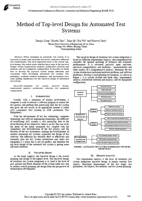
Method of Top-level Design for Automated TestSystemsZhenjie Zeng1, Xiaofei Zhu1,*, Shiju Qi1, Kai Wu2 and Xiaowei Shen11Rocket Force University of Engineering, Xi’an, China2Troops No. 96604, Beijing, China*Corresponding authorAbstract—When designing an automatic test system, it is necessary to make each electronic test device conform to different test requirements. The most important issue is the system top-level design. The article starts with the three steps of the top-level design: system requirements analysis, architecture selection and analysis, and test equipment configuration. It describes in detail how to develop the top-level system design efficiently and reasonably when developing automated test systems. The principles, available method techniques, and precautions have some guiding significance for the top-level design of automated test systems.Keywords—automatic test system; top-level design; requirements analysis; architecture selection; test equipment configurationI.I NTRODUCTIONUsually, with a minimum of human involvement, a computer is used to execute a software program to control the test process and perform data processing until the test system that gives the test results in an appropriate manner is called ATS (Automatic Test System) or ATE (Automatic Test Equipment). .With the advancement of test bus technology, computer technology and software engineering technology, the difficultyof establishing ATS systems is also increasing. Due to the diversification of test objectives, there is no bus that can cover the needs of the entire automated test, coupled with the complexity and diversification of the test process and the function of the test instruments, making the establishment of modern automated test systems, especially the design of test software. The difficulty has doubled. How to effectively and rationally plan the test system architecture and select test equipment is a place that is not yet perfect, and therefore the top level design of the automatic test system is getting more and more attention.II.T OP-LEVEL D ESIGNAs the name suggests, the top-level design is the overall planning and design at the highest level. The top-level design of automatic test system integration is to stand at the level of past, present and future demands of the system under test, and to conduct overall planning and design from the perspective of technological development.The top-level design of automatic test system integration is based on sufficient requirements analysis, and comprehensively considers the optimal matching of technical and economic performances. It is advanced, practical, open, real-time, universal (compatibility), and reliability. , maintainability and other aspects of a comprehensive analysis, determine the test system architecture (including hardware platforms and software platforms), develop a corresponding test program. As shown in Figure 1, it is usually divided into three steps: requirements analysis, architecture selection and analysis, and test equipment configuration.AemandanalysisArchitectureselection andanalysisTest equipmentselection andconfigurationFunctional AnalysisTarget signal typeMeasured parameter definitionTestability analysisTest method analysisInterface bus analysisHardware architecture analysisController selection and analysisHardwareplatformSoftware operating environment analysisOperating system selection and analysisDevelopment platform selection and analysisDatabase selection and analysisTest instrument (module) selectionUTT interface connection designSpecial parameters require processingSoftwareplatformFIGURE I. AUTOMATIC TEST SYSTEM INTEGRATION TOP LEVELDESIGN FLOWIII.D EMAND A NALYSISTest requirement analysis is the basis of automatic test system integration top-level design. It mainly contains five aspects: functional requirements of the test target, test parameters, test objects, test methods, and test system planning.3rd International Conference on Electrical, Automation and Mechanical Engineering (EAME 2018)A.Test Target Functional RequirementsThe different requirements of the test equipment working platform determine the test speed requirements, and also determine the different requirements of the online/offline test; the main control method and logic of the tested equipment determines the difference between the test procedures and methods; the input frequency of the tested equipment, Different parameters, such as amplitude and modulation method, determine the overall requirements for the operating frequency band, small signal level (minimum leakage), and waveform parameters of the automatic test system analog signal source; the output and content of the device under test determines the signal sampling of the automatic test system. The data acquisition method is different; the digital communication interface of the device under test determines that the digital communication interface that the automatic test system should have is different from the protocol; the testability interface of the device under test determines the final test capability and fault diagnosis ability of the automatic test system.B.Test ParametersThe test parameter analysis includes analysis: the form of the measured parameter (electrical or non-electrical, digital or analog, etc.), range and quantity; performance index (measurement accuracy and speed, etc.); the form and range of the excitation signal. In particular, when analyzing requirements for a top-level design of a general-purpose comprehensive automatic test system that is suitable for multiple systems, multiple protocols, and multiple equipment, comprehensive analysis is often required to integrate the test parameters.C.Test ObjectThe test objects vary widely. When analyzing the test objects, a comprehensive analysis must be performed in conjunction with the test system requirements of the test objects. In the face of a specific test object test system or subsystem, the description can use a variety of expressions to give different models of the test system at different levels of simplification, such as language descriptions, graphics, and mathematical formulas. As a simplified description of some test systems, their models merely express their basic characteristics, often ignoring irrelevant details in order to simplify their complexity. For a complex test object test system, a model is inevitably limited by some assumptions in its design and utility. These conditions often have some ambiguity and basically reflect an implicit conceptual idea. Therefore, when analyzing the requirements of a specific test object, it is usually necessary to establish a corresponding test system model.D.Test MethodsAccording to the functional requirements of the test target, a corresponding test method is formulated for the “face-to-face automatic test system” or “object-oriented automatic test system”.. E.Test System PlanningWhen developing an automated test system, it often takes a lot of time to complete the test-assisted tasks such as creating files and programming supporting test software. The test application software development platform can standardize all kinds of test processes and integrate an operating system that is suitable for various test and post-processing functions. It can help us to complete these test auxiliary work; therefore, we use this kind of test platform to conduct various tests. When testing, you can save a lot of time.IV.A RCHITECTURE S ELECTION AND A NALYSIS On the basis of sufficient requirements analysis, determining the architecture of the automated test system is the most critical step in the top-level design. That is how to determine the test plan from the perspective of the top-level design, and select the hardware platform and software platform architecture of the automatic test system, and the most important one is the selection of the test equipment digital communication interface bus.A.System Test Plan SelectionThe system test plan is the overall concept of product testing. It specifies the type of product testing, when (continuous or regular) testing, where (field or workshop, or which maintenance level), testing methods, and test methods used. The types of system test can be divided into: system-wide test and departmental system test, static test and dynamic test, online test and offline test, quantitative test and qualitative test, continuous test and periodic test, etc. The test level can be divided into three levels according to the location: production site, use site, and maintenance base. The test system (equipment) operating methods are generally:According to the use of the operation can be divided into three kinds of automatic, semi-automatic and artificial; according to the general degree of application can be divided into two kinds of special and general equipment; according to the association with the product can be divided into two kinds of BITE and external test equipment.Most of the test methods used in automated testing have so far been modeled on manual tests, from the measurement principles used, the testing techniques used, to the test procedures performed, except that computers were used instead of manual operations. As far as the characteristics and potential of automatic testing are concerned, fundamental reforms of the test plan are needed for future research.B.Selection of Test Equipment Digital CommunicationInterface Bus and ATS StructureThe development of automatic test systems has promoted the continuous emergence of various general-purpose test equipment interface buses and rapid technological advancement: from the early GPIB, CAMAC to the recent VXI, MXI, PCI, PCIe, PXI, PXIe, cPCI, MMS, IEEE1394 ( Firewire), USB, etc. Although technical characteristics are not the same, they are widely used.The structural elements of a modern automated test system are programmable test instruments, test controllers, interconnected standard digital interfaces, and software systems. At present, modern automatic testing has been widely used, and the test objects faced are large, complex, and diversified, making it impossible for an automatic test system based on any kind of bus technology to cover the needs of the entire test object.Multi-bus fusion automatic test system structure shown in Figure 2. It consists of test instruments, DUTs(design under test) and UUT(unit under test) interfaces, test controllers (computers), various general-purpose digital interface buses, and test software. The test controller is interconnected with the test instrument through the digital interface bus, and the device under test is connected to the input/output terminal of the test instrument through the UUT interface. The digital interface bus used may be GPIB, VXI, PXI, LXI, or even an internal computer bus (AT/EISA/PCI), or their convergence. Once the standard digital interface bus architecture used is determined, the automatic test system architecture is basically selected. In an automatic test system, regardless of the interface bus architecture, an external computer or built-in computer system can be selected as the test system controller. The choice of the test system controller should fully consider the optimal matching of technical and economic performance, and choose from real-time, practical, reliable, flexible and convenient.CAT test hostMaster control computerGPIB instrument PC card typeinstrumentVXIinstrumentPXIinstrumentUUT interfaceUUT……FIGURE II. MULTI-BUS FUSION AUTOMATIC TEST SYSTEMSTRUCTUREC.Test Software Platform Mode SelectionIn modern computer-based automated test systems, hardware is the foundation and software is the soul. Test software has increasingly become the main body of ATS, which determines the advanced nature, reliability, practicality, and real-time performance of the entire automated test system.The automatic test software platform mainly refers to the programming language and software support environment involved in the test application software design. It is an integrated software platform such as a computer operating system, a test programming language, a database software, and a program diagnosis software. The key element is Test programming language. Since the automatic test system was popularized and applied, there have been great developments in testing programming languages from low-level to high-level, to the current test application development environment.V.T EST E QUIPMENT C ONFIGURATION After the system structure of the test system is determined, the next task is to synthesize the test contents according to the requirements analysis, and to match the corresponding test equipment according to the test content requirements. There are three types of optional test equipment: general test equipment, special purpose equipment, and test interface adapter.A.Universal Test EquipmentThe universal test equipment includes a main box, a test controller, a main control interface, a zero slot controller, an instrument module, and a desktop instrument. The following factors should be considered when selecting the type of equipment: (1) The higher the degree of equipment automation, the shorter the time for detecting and isolating faults, and the less the manpower consumption, but the cost of test equipment will increase and more protection is needed. (2) Differences in capabilities between the two are to be considered when selecting a BIT (Built-in-Test) and an off-board automatic test equipment. (3) When the BIT is used in conjunction with the off-board automatic test, make full use of the BIT capability of each unit under test. (4) When selecting a dedicated or general-purpose device, it is necessary to consider that the special-purpose device is simple and convenient to use and has high efficiency, but the use range is narrow. (5) The main selection of instrument and equipment is based on the requirements of test parameters, characteristics of the signal to be measured, and range selection. When selecting the instrument module, pay attention to the size of the bus module, power, and number of slots.B.Special Purpose EquipmentWhen the test is not ready for selection, in addition to the above-mentioned common tests, when preparing for the following situations, it may be considered to develop or develop special purpose instrument (module) equipment. When the current product can not meet the test requirements, multiple instruments and equipments are required to complete the measurement together. However, the utilization rate of each instrument is very low or can be accomplished with one instrument. When the price is high and the utilization rate is low, the use of development or development is considered. Special purpose instrument.C.Test Interface Adapter DesignFor different test objects, the extraction and feeding of various test signals requires the design and manufacture of various test interfaces and special fixtures. In the automatic test system, especially the automatic test system assembly of complex electronic equipment, the requirements of the same type but different models and different test objects existuniversally, and often require the test system group to build a relatively universal automatic test platform. Through this platform, different test modules and test methods can be used to quickly and easily complete the automatic test system set-up (configuration) task for different test objects; however, the test interface and the dedicated test module cannot be matched and can only be tested according to the device under test. The test requires the development of a test interface adapter.VI.C ONCLUSIONThis article starts with the three steps of the top-level design: system requirements analysis, architecture selection and analysis, and test equipment configuration. It describes in detail how to perform top-level design efficiently and reasonably when developing automated test systems, and analyzes what the design must follow. Principles, methods, techniques, and precautions have certain guiding significance for the top-level design of automated test systems.R EFERENCES[1]LI Xing-shan, ZUO Yi, SUN Jie. Automatic Test System IntegrationTechnology[M]. Publishing House of Electronics Industry, 2004.[2]QIN Hong-lei, LU Hui et al. Automatic Test System. Beijing: HigherEducation Press, 2007[3]LIU Si-jiu, ZHANG Li-yong. Automatic Test System and VirtualInstrument. Beijing: Publishing House of Electronics Industry, 2009 [4]GU Zhi-yong, TENG Peng, HU Shi-guo, et al. Top-level design of ATSoverall plan for integrated helicopter display systems[J]. Electro-optics and Control, 2008, 15(11):59-62.[5]GU Ya-ping. Research on Top Design of VXI Bus TestingTechnology[J]. Electronic Testing, 1998(8):22-23.。
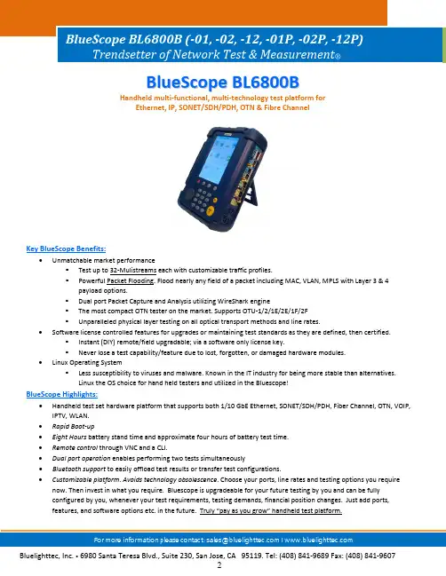
B l u e S c o p e B L6800BHandheld multi‐functional, multi‐technology test platform forEthernet, IP, SONET/SDH/PDH, OTN & Fibre ChannelKey BlueScope Benefits:∙Unmatchable market performance▪Test up to 32‐Mulistreams each with customizable traffic profiles.▪Powerful Packet Flooding. Flood nearly any field of a packet including MAC, VLAN, MPLS with Layer 3 & 4 payload options.▪Dual port Packet Capture and Analysis utilizing WireShark engine▪The most compact OTN tester on the market. Supports OTU‐1/2/1E/2E/1F/2F▪Unparalleled physical layer testing on all optical transport methods and line rates.∙Software license controlled features for upgrades or maintaining test standards as they are defined, then certified.▪Instant (DIY) remote/field upgradable; via a software only license key.▪Never lose a test capability/feature due to lost, forgotten, or damaged hardware modules.∙Linux Operating System▪Less susceptibility to viruses and malware. Known in the IT industry for being more stable than alternatives.Linux the OS choice for hand held testers and utilized in the Bluescope!BlueScope Highlights:∙Handheld test set hardware platform that supports both 1/10 GbE Ethernet, SONET/SDH/PDH, Fiber Channel, OTN, VOIP, IPTV, WLAN.∙Rapid Boot‐up∙Eight Hours battery stand time and approximate four hours of battery test time.∙Remote control through VNC and a CLI.∙Dual port operation enables performing two tests simultaneously∙Bluetooth support to easily offload test results or transfer test configurations.∙Customizable platform. Avoids technology obsolescence. Choose your ports, line rates and testing options you require now. Then invest in what you require. Bluescope is upgradeable for your future testing by you and can be fullyconfigured by you, whenever your test requirements, testing demands, financial position changes. Just add ports,features, and software options etc. in the future. Truly “pay as you grow” handheld test platform.Ethernet & IPBlueScope Ethernet Standard Features: ∙ Throughput Test (Single Stream)∙ Packet Filtering∙ IP Tools (Ping, DHCP, Trace Route)∙ In ‐Service Traffic Monitoring (Non ‐Intrusive Mode) ∙ MPLS (stacking up to 3 MPLSs) ∙ VLAN, Q ‐in ‐Q (up to 3 VLANs) ∙ Cable Diagnostics ∙ Remote Control via VNC ∙ Report Generation (PDF, CSV and TXT)BlueScope Ethernet SW Options:∙ (ET ‐1) Single 1GB port (ET ‐2) Dual 1GB port (ET ‐3) Single 10GB port(ET ‐4) Dual 1GB & Single 10GB port∙ (ET ‐5) Loopback Mode (L1‐L4, auto, filtered) ∙ (ET ‐6) Throughput multi ‐streams (4 streams)∙ (ET ‐7) RFC2544 (Network Equipment Benchmarking Test) ∙ (ET ‐8) Packet Capture and Decode via WireShark ∙ (ET ‐9) Throughput 32 multi ‐streams∙ (ET ‐10) Packet Flooding – Mac/VLAN/IP/User Defined Field ∙ (ET ‐11) L1/Unframed BERT (Cable BERT ‐RJ45, Unframed BERT ‐SFP Optic)∙ (ET ‐12) Network Discovery ∙ (ET ‐13) 100 FX/LX (Optic)BlueScope Ethernet SW Options:∙ (ET ‐14) Y.1564(EtherSAM)∙ (ET ‐15) PBB/PBB ‐TE(MAC ‐in ‐MAC) ∙ (ET ‐16) SyncE/1588 ∙ (ET ‐17) IPV6∙ (ET ‐18) EtherOAM Y.1731 (available early 2013) ∙ (ET ‐19) Asymmetric Testing (available early 2013)∙ (ET ‐20) One ‐Way Delay Measurement using 1588 or GPS (available early 2013)∙ (ET ‐21) Web Browser and HTTP Testing ∙ (ET ‐22) CLI Interface ∙ (WA ‐1) 10GbE WAN PHY∙ (WA ‐2) WLAN 802.11 a/b/g testing ∙ (PT ‐1) IPTV Quality Metrics∙ (PT ‐2) IPTV Decode (available early 2013) ∙ (VO ‐1) VoIP Quality Metrics∙ (VO ‐2) VoIP Signaling and Vocoding (available early 2013)Ethernet IP Applications∙Troubleshoots Ethernet/IP networks, captures and analyzes packets, and identifies network problems.∙Tests Carrier Ethernet transport to verify class of service (CoS), Triple‐Play Service, and Ethernet circuit transparency.∙Supports Packet Transport Network (PTN) testing with MPLS‐TP traffic generation and QoS analysis, along with simultaneous verification of OAM Label 13 or 14 operation.∙Confirms higher‐layer Ethernet data applications and services at 10Mbps to 1Gbps rates with Ipv4 and IPv6∙Tests Layer 1‐4 Ethernet/IP SLAs with RFC 2544 for up to 3 VLAN tags, Q‐in‐Q, and MPLS encapsulation.∙Verifies automatically SLA compliance according to Y.1564, including different traffic profiles per service, and KPI compliance for all committed services concurrently.Ethernet IP Testing LifecycleInstallation∙RFC2544, including frame delay variation, asymmetric rates, and concurrent results to reduce overall test time.∙Y.1564 EtherSAM automated SLA validation including bandwidth profiles and KPI compliance for quickly verifying multiple services.∙Carrier Ethernet testing with PBB, MPLS, MPLS‐TP, VLAN and Q‐in‐Q.Troubleshooting∙Line rate packet capture up to 10Gbps.∙Packet decodes with integrated WireSharkCarrier Ethernet Installation TestingFor years Ethernet/IP has been transported throughout carrier networks encapsulated in other data‐link layer technologies thatevolved into a carrier‐grade technology because of operations, administration, and maintenance (OAM) standards such as ITU‐Ty.1731, IEEE 802.1ag, and 802.3ah. Ethernet now possesses many of the characteristics that made SONET/SDH the transporttechnology of choice; end‐to‐end circuit transparency, redundancy, and full‐featured OAM for circuit‐based performancemanagement and alarming. The BlueScope delivers a much‐needed tool set for provisioning and troubleshooting Ethernet networksthat substantially improves installation and troubleshooting times, thereby granting error‐free operation and a significant reductionin operating expense.RFC2544 TestingThe BlueScope delivers all the Carrier Ethernet testing needed to qualify Ethernet‐based transport networks. RFC2544 is the defacto industry standard for Ethernet circuit installation. In addition to supporting Ethernet throughput or committed information rate (CIR), frame delay (FD) or latency, frame loss (FLR), and back‐to‐back burst testing as called out in the RFC, the BlueScope also tests forpacket jitter or frame delay variation (FDV) to ensure the circuit is ready to transport time‐sensitive services such as IPTV and VoIP.Using a pair of test sets and Asymmetric RFC testing, users can validate Ethernet Virtual Circuits (EVCs) with different upstream and downstream CIRs, or they can test sequentially in both directions to ensure that key performance indicators (KPIs) are met acrossany connection type.ITU‐T Y.1564 EtherSAM Service Activation TestingY.1564 EtherSAM allows for fast and easy verification of SLAs for differentiated services including validation of different bandwidthprofiles like committed information rate (CIR), extended information rate (EIR) and maximum bandwidth. Pass / Fail results for KPIs including CIR, frame delay (FD), frame delay variation (FDV or packet jitter) and frame loss rate (FLR) are provided independently forup to 16 services. Out of sequence frames and available seconds are reported per Y.1564.Verifying CoS with Multiple StreamsMulti‐stream testing generates several streams of traffic at the Ethernet, IP, and TCP/UDP layers (Layers 2‐4) to emulate various types of traffic with the appropriate CoS mappings so that users can assess the impact of traffic prioritization on the overall network architecture while confirming proper network element queuing, policing, and shaping. Up to 32 individually configured streams enable generation and analysis of per stream key parameters such as VLAN ID and priority, TOS/DSCP marking, packet size,source/destination IP and MAC address, and source/destination TCP/UDP ports. Users can configure constant or ramp traffic to simulate near real‐world traffic before actually delivering a service. This level of testing confirms the network design as well as drastically reduces post‐installation troubleshooting.BER and Latency TestingThe BlueScope supports optical Layer 1 (L1) BER testing for stress testing the underlying physical transport link. A standard 2^23 pattern is used to obtain key QoS measurements including bit error rates, pattern sync, latency, line coding, and signal/power levels.Ethernet OAM, VLAN, Q‐inQ, MPLS and PBB Tunneling TechnologiesEthernet tagging and encapsulation is commonly used to improve the scalability of Ethernet networks by isolating customer traffic and, in the case of provider backbone bridging (PBB), minimizing the number of MAC addresses that equipment must learn. Regardless of the encapsulation and tagging used, the BlueScope tests CoS to confirm KPIs such as CIR, FD, FDV, and FLR. Support for virtual local area network (VLAN) tags, Q‐in‐Q VLAN tags, PBB (also known as MAC‐in‐MAC) and multi‐protocol label switching (MPLS), the BlueScope allows testing at any part of the Metro network.Ethernet Timing Synchronization Verification using 1588v2 PTP and G.826x SyncECritical network timing and frequency synchronization testing enables service providers to analyze emerging 1588v2 PTP and Synchronous Ethernet (SyncE) protocols greatly reducing expenses for mobile backhaul and LTE by eliminating the need forTDM/GPS. Wireless backhaul providers can now verify whether Ethernet links can transfer PTP protocols by connecting to a PTP master and measuring critical packet parameters such as PDV with simultaneous network traffic loading. SyncE testing recovers the timing of an incoming Ethernet interface for the tester’s transmitter. Capturing and decoding the 1588v2 PTP and Ethernet Synchronization Messaging Channel (ESMC) messages allows operators to verify and troubleshoot proper configuration and operation of synchronization networks.Carrier Ethernet Fault IsolationIn the ever‐changing Ethernet and IP world providers must quickly, cost‐efficiently, and reliably troubleshoot problems at all layers of the stack. The BlueScope provides powerful line‐rate packet capture at Ethernet speeds up to 1GigE without dropping a single packet. When troubleshooting problems occur intermittently or inconsistently, it supports multiple traffic filters and triggers, including 16‐byte pattern identification, to isolate the exact problem and minimize the amount of information gathered.The BlueScope natively supports WireShark for on‐instrument packet decode. Additionally, users can save the captured traffic in a standard pcap file format and export it via USB or FTP through the management port for further analysis.SONET/SDH/PDHThe BlueScope 6800B performs BER testing on all line interfaces in end‐to‐end or loopback applications, inserts errors and alarms to verify NE conformance and connectivity, and measures BERs from DS1 (1.5M)/E1 (2.048M) rates to OC‐192/STM‐64.MappingsSONET/SDH mappings include all intermediate mappings down to VC‐4/VC‐3 in addition to BERT payload with multiple PRBS choices.SONET/SDH/PDH Overhead Byte Manipulation and AnalysisUsing the overhead byte manipulation and analysis capability, users can modify K1 and K2 bytes to test automatic protection switching (APS) to specify and identify user‐configurable path trace messages and payloads. The path overhead (POH) capture feature facilitates troubleshooting end‐to‐end problems. The Bluescope 6800B supports manual capture, capture on alarm, and capture based on user‐defined triggersPhysical Layer TestingPerform physical layer testing to verify dark fiber and line continuity across all optical transport methods and line rates. Support for unframed STM‐1/4/16/64, Fiber Channel 1x/2x/4x/10x, OTN OTU‐1/2/1E/2E/1F/2F, 1.250G(1GE), 10.313(10GE) and 3.1G (CPRI).Service Disruption measurementsThe Bluescope 6800B measures the protection switch times of SONET/SDH rings and their effects on tributaries. By measuring various error and alarm conditions on the tributaries, providers can verify that their transport network is providing adequate redundancy to guarantee SLAs.Multi‐Channel ViewDrill down to view the path hierarchy in its entirety on one screen with automatic detection of payload type (concatenated or non‐concatenated) for SONET ( 48x STS‐1 and 28x VT 2/1.5) and SDH (48x AU‐3 and 28x TU12/TU11).Line Through ModeConnecting the test unit in‐line provides not only monitoring capabilities but also the possibility of injecting errors. This provides for an effective tool in serice‐disruption testing.SDH/PDH Alarm/Error GenerationGenerate Alarms for:LOS, LOF, OOF,RS‐TIM, MS‐AIS, MS‐RDI, AU‐LOP, AU‐AIS, TU‐LOP, TU‐AIS, HP‐UNEQ, HP‐PLM, HP‐TIM, HP‐RDI,HP‐SRDI, HP‐CRDI, HP‐PRDI, HP‐TC‐UNEQ, HP‐TC‐LOMF, HP‐TC‐AIS, HP‐TC‐RDI, HP‐TC‐ODI, LP‐UNEQ, LP‐PLM, LP‐TIM, LP‐RFI, LP‐RDI, LP‐SRDI, LP‐CRDI, LP‐PRDI, LP‐TC‐UNEQ, LP‐TC‐LOMF, LP‐TC‐AIS, LP‐TC‐RDI, LP‐TC‐ODIGenerate Errors for:FAS, B1, B2,B3, MS‐REI, BIT,HP‐REI, HP‐TC‐IEC, HP‐TC‐REI, HP‐TC‐OEI, LP‐BIP, LP‐REI, LP‐TC‐IEC, LP‐TC‐REI, LP‐TC‐OEIBlueScope SONET/SDH Options:∙(SO‐1) OC‐3/12/48 (STM 1/4/16)(SO‐2) OC‐192 (STM‐64)(SO‐3) OC‐3/12/48/192 (STM 1/4/16/64)∙(SO‐4) Unframed Line Rate (Requires SO‐1,2 or 3)∙(SO‐5) Multi‐Channel View (Requires SO‐1, 2 or 3)∙(SO‐6) Signal Delay emulator (injection of signal delay in unframed line rates; Requires SO‐4)BlueScope PDH Options: ∙(PD‐1)E1/T1 (DS1)(PD‐2)E3/T3 (DS3)(PD‐3)E1/T1, E3/T3OTNOTN is the next generation network designed to combine and accelerate the benefits of SDH/SONET with the bandwidth expandability of DWDM (Dense wavelength division multiplexing).Test end‐to‐end connectivity by transmitting and receiving OTN signals with the ability to insert and analyze errors and alarms in network troubleshooting and equipment verification applications.TCM with Error/Alarm detectionVerify network element interoperability with the TCM bytes; Count, current rate and average rate for each error, SDT (Service disruption Time) measurements and RTD (Round Trip Delay) measurements. Verify OTN alarms and errors with injection capabilities such as loss of frame (LOF), alarm indication signal (AIS), and backward defect indication (BDI).FEC TestingTransmit and analyze correctable and uncorrectable FEC errors to verify a network element’s ability to correct conditions through the use of FEC enabled signals. Correctable and uncorrectable FEC error positions are accumulated and monitored through a graphical hierarchy window which allows users to easily recognize the position of the FEC error.Features programmable FEC error generation functions that allows the user to define a detailed position for correctable FEC errors and un‐correctable FEC errors.Line Through ModeConnecting the test unit in‐line provides not only monitoring capabilities but also the possibility of injecting errors. This provides for an effective tool in service‐disruption testing.BlueScope OTN Options:∙(OT‐1)OTU‐1 (2.66G/STM‐16)Requires SO‐1(OT‐2)OTU‐2 (10.7G/STM‐64)Requires SO‐2(OT‐3)OTU‐3 (2.66G & 10.7G / STM‐16 & STM‐64) Requires SO‐3(OT‐4)OTU‐4 (10G Ethernet over OTU‐2 [OUT‐1e/2e] available early 2013)Fibre ChannelThe BlueScope B6800B tests 1x, 2x, 4x and 10x Gbps Fibre Channel (FC). Users can manipulate various fields of the FC frames to emulate end customer traffic and perform BER measurements on L1 and L2 circuits. The BlueScope supports buffer crediting capability, which lets providers verify the effect of delay on the link throughput and test the ability of the link to obtain the optimum buffer credit values. The BlueScope also allows users to turn up storage area networks (SANs), producing reliable throughput, packet loss, RTD, and burstability results with consistent test methodology.BlueScope Fiber Channel Options:∙(FC‐1) Fiber Channel 1x/2x(FC‐2) Fiber Channel 4x(FC‐3)Fiber Channel 1x/2x/4x(FC‐4)Fiber Channel 10x (Available 2013)(FC‐5)Fiber Channel 1x/2x/4x/10x (10x Available 2013)Hardware Specifications:∙Ports:▪(2) SFPs (1000BASE‐SX/LX/ZX, 100‐FX/LX/SX)▪(2) 10/100/1000Base‐T (RJ45)▪(1) XFP▪(1) BNC connectors (Tx/Rx) 34‐45M▪(1) Bantam(Tx/Rx) : 1.5M ‐ 2M▪(1) SMA(Tx) : Tx Reference Clock Out▪(1) SMA: External clock input 1.544 ‐2.048 Mbps / 1.544m, 2.048 m, 10M / Any clock speed▪(1) GPS Signal input▪(1) HDMI output▪(1) 3.5mm headset audio jack and mic support.∙Port Configuration:▪BL6800‐01 (1Gb‐Single Port), BL6800‐02 (1Gb‐Dual Port), BL6800‐12 (10Gb‐Single Port, 1Gb‐Dual Port)▪BL6800‐01P (including PDH), BL6800‐02P (including PDH), BL6800‐12P (including PDH) ∙Dimensions:▪Size: 172.5 (W) x 227 (H) x 58.5 (D) mm▪Weight: 1.3 kg with Battery, Battery (0.3 kg)∙Operating Temp: 0Ԩ~40Ԩ∙Storage Temp: ‐20Ԩ~ +70Ԩ∙Display: 5.7 Color TFT‐LCD Touch Screen∙User Interface: Touch Screen & Keypad∙Humidity: 10% ~ 90%∙Power:▪AC adaptor: 100V~240 V(50Hz/60Hz)▪Removable/Rechargeable lithium ‐Ion Battery▪Battery life: 3 hours typical, 8 hour in standby mode▪Charging time: 1 ~ 2 hours∙Memory:▪16GByte internal Flash memory includedContact Information:Web: US & Canada:Support: ************************Tel: +1 408 841 9689Sales: **********************Fax: +1 408 841 9607。
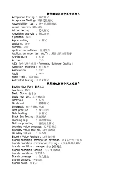
软件测试部分中英文对照A Acceptance test ing:验收测试Acceptance Testing:可接受性测试Accessibi l i t y test:软体适用性测试actual outcome:实际结果Ad hoc test ing:随机测试Algorithm analysis:算法分析algori thm:算法Alpha test ing:α测试analysis:分析anomaly:异常applicat ion software:应用软件Applicat ion under test(AUT) :所测试的应用程序Architecture:构架Arti fact:工件AS Q:自动化软件质量(Automated Software Quality)Assertion checking :断言检查Associat ion:关联Audit:审计audit trai l:审计跟踪Automated Testing:自动化测试软件测试部分中英文对照BBackus-Naur Form:BNF范式baseline:基线Basic Block:基本块basis test set:基本测试集Behaviour:行为Bench test:基准测试benchmark:标杆/指标/基准Best practise:最佳实践Beta test ing:β测试Black Box Testing:黑盒测试Blocking bug :阻碍性错误Bottom-up test ing:自底向上测试boundary value coverage:边界值覆盖boundary value test ing:边界值测试Boundary values :边界值Boundry Value Analysis:边界值分析branch condit ion combination coverage:分支条件组合覆盖 branch condit ion combination test ing:分支条件组合测试 branch condit ion coverage:分支条件覆盖branch condit ion test ing:分支条件测试branch condit ion:分支条件Branch coverage :分支覆盖branch outcome:分支结果branch point:分支点branch test ing:分支测试branch:分支Breadth Testing:广度测试Brute force test ing:强力测试Buddy test:合伙测试Buffer:缓冲Bug:错误Bug bash :错误大扫除bug f ix:错误修正Bug report:错误报告Bug tracking system: 错误跟踪系统bug:缺陷Build:工作版本(内部小版本)Build Verficat ion tests(BVTs):版本验证测试Build-in:内置软件测试部分中英文对照CCapabil i ty Maturity Model (CM M): 能力成熟度模型Capabil i ty Maturity Model Integrat ion(CM MI):能力成熟度模型整合capture/playback tool:捕获/回放工具Capture/Replay Tool:捕获/回放工具CAS E:计算机辅助软件工程(computer aided software engineering)CAST:计算机辅助测试cause-effect graph:因果图cert i f i cat ion:证明change control:变更控制Change Manage ment :变更管理Change Request :变更请求Character Set :字符集Check In:检入Check Out :检出Closeout :收尾code audit:代码审计Code coverage :代码覆盖Code Inspection:代码检视Code page :代码页Code rule:编码规范Code sytle:编码风格Code W alkthrough:代码走读code-based test ing:基于代码的测试coding standards:编程规范Co m m o n sense :常识Co mpatibi l i t y Testing:兼容性测试complete path test ing:完全路径测试 completeness:完整性complexity:复杂性Co mponent test ing:组件测试Co mponent:组件computation data use:计算数据使用computer system security:计算机系统安全性 Concurrency user :并发用户Condit ion coverage :条件覆盖condit ion outcome:条件结果condit ion:条件configurat ion control:配置控制Configurat ion i tem :配置项configurat ion manage ment:配置管理Configurat ion test ing:配置测试conformance cri ter ion: 一致性标准Conformance Testing: 一致性测试consistency : 一致性consistency checker: 一致性检查器Control f low graph :控制流程图control f low graph:控制流图control f low:控制流conversion test ing:转换测试Core team:核心小组correct ive maintenance:故障检修correctness :正确性coverage :覆盖率coverage i tem:覆盖项crash:崩溃cri t i ca l i t y analysis:关键性分析cri t i ca l i t y:关键性CR M(change request manage ment):变更需求管理Customer-focused mindset :客户为中心的理念体系Cyclomatic complexity:圈复杂度软件测试部分中英文对照D data corruption:数据污染data defini t ion C-use pair:数据定义C-use使用对 data defini t ion P-use coverage:数据定义P-use覆盖 data defini t ion P-use pair:数据定义P-use使用对 data defini t ion:数据定义data defini t ion-use coverage:数据定义使用覆盖 data defini t ion-use pair:数据定义使用对 data defini t ion-use test ing:数据定义使用测试 data dict ionary:数据字典Data Flow Analysis:数据流分析data f low analysis:数据流分析data f low coverage:数据流覆盖data f low diagram:数据流图data f low test ing:数据流测试data integri ty:数据完整性data use:数据使用data validat ion:数据确认dead code:死代码Debug:调试Debugging:调试Decision condit ion:判定条件Decision coverage :判定覆盖decision coverage:判定覆盖decision outcome:判定结果decision table:判定表decision:判定Defect:缺陷defect density:缺陷密度Defect Tracking :缺陷跟踪Deployment :部署Depth Testing:深度测试design for sustainabi l i t y:可延续性的设计 design of experiments:实验设计design-based test ing:基于设计的测试Desk checking :桌前检查desk checking:桌面检查Determine Usage Model :确定应用模型Determine Potential Risks :确定潜在风险 diagnostic:诊断DIF(decimation in frequency) :按频率抽取dirty test ing:肮脏测试disaster recovery:灾难恢复DIT (decimation in t ime):按时间抽取 documentation test ing:文档测试 domain test ing:域测试domain:域DTP DETAIL TEST PLAN详细确认测试计划Dyna mic analysis:动态分析dynamic analysis:动态分析Dyna mic Testing:动态测试软件测试部分中英文对照E embedded software:嵌入式软件emulator:仿真End-to-End test ing:端到端测试Enhanced Request :增强请求enti ty relat ionship diagram:实体关系图 Encryption Source Code Base: 加密算法源代码库 Entry cri ter ia:准入条件entry point:入口点Envisioning Phase:构想阶段Equivalence class :等价类Equivalence Class:等价类equivalence part i t ion coverage:等价划分覆盖Equivalence part i t ion test ing:等价划分测试equivalence part i t ion test ing:参考等价划分测试equivalence part i t ion test ing:等价划分测试Equivalence Parti t ion ing:等价划分Error:错误Error guessing :错误猜测error seeding:错误播种/错误插值error:错误Event-driven :事件驱动Exception handlers:异常处理器exception:异常/例外executable statement:可执行语句Exhaustive Testing:穷尽测试exit point:出口点expected outcome:期望结果Exploratory test ing:探索性测试软件测试部分中英文对照FFailure:失效Fault:故障fault:故障feasible path:可达路径feature test ing:特性测试Field test ing:现场测试FM E A:失效模型效果分析(Failure Modes and Effects Analysis)FM E C A:失效模型效果关键性分析(Fai lure Modes and Effects Crit ical i t y Analysis) Framework :框架FTA:故障树分析(Fault Tree Analysis)functional decomposit ion:功能分解Functional Specif icat ion:功能规格说明书Functional test ing:功能测试Functional Testing:功能测试软件测试部分中英文对照GG11N(Globalizat ion):全球化Gap analysis:差距分析Garbage characters:乱码字符glass box test ing:玻璃盒测试Glass-box test ing:白箱测试或白盒测试Glossary :术语表G UI(Graphical User Interface):图形用户界面软件测试部分中英文对照H-MHard-coding :硬编码Hotfix:热补丁IGKL M NI18N(Internat ional izat ion):国际化Identi fy Exploratory Tests –识别探索性测试IEEE:美国电子与电器工程师学会(Inst i tu te of Electr ical and Electronic Engineers)Incident事故Incremental test ing:渐增测试incremental test ing:渐增测试infeasible path:不可达路径input domain:输入域Inspection :审查inspection:检视instal labi l i t y test ing:可安装性测试Instal l i ng test ing:安装测试instrumentation:插装instrumenter:插装器Integrat ion:集成Integrat ion test ing:集成测试interface :接口interface analysis:接口分析interface test ing:接口测试interface:接口inval id inputs:无效输入isolat ion test ing:孤立测试Issue :问题Iterat ion:迭代Iterat ive development:迭代开发job control language:工作控制语言Job:工作Key concepts :关键概念Key Process Area :关键过程区域Keyword driven test ing:关键字驱动测试Kick-off meeting :动会议L10N(Localizat ion):本地化Lag t ime :延迟时间LCSAJ:线性代码顺序和跳转(Linear Code Sequence And Jump)LCSAJ coverage:LCSAJ覆盖LCSAJ test ing:LCSAJ测试Lead t ime :前置时间Load test ing:负载测试Load Testing:负载测试Localizabi l i t y test ing:本地化能力测试Localizat ion test ing:本地化测试logic analysis:逻辑分析logic-coverage test ing:逻辑覆盖测试Maintainabi l i t y:可维护性maintainabi l i t y test ing:可维护性测试Maintenance :维护Master project schedule :总体项目方案Measurement :度量Me m ory leak :内存泄漏Migration test ing:迁移测试Milestone :里程碑Mock up :模型,原型modified condit ion/decision coverage:修改条件/判定覆盖 modified condit ion/decision test ing:修改条件/判定测试 modular decomposit ion:参考模块分解Module test ing:模块测试Monkey test ing:跳跃式测试Monkey Testing:跳跃式测试mouse over:鼠标在对象之上mouse leave:鼠标离开对象MTB F:平均失效间隔实际(mean t ime between fai lures)MTP M AIN TEST PLAN主确认计划MTTF:平均失效时间 (mean t ime to fai lure)MTT R:平均修复时间(mean t ime to repair)multip le condit ion coverage:多条件覆盖mutation analysis:变体分析软件测试部分中英文对照N-RN/A(Not applicable):不适用的Negative Testing :逆向测试,反向测试,负面测试negative test ing:参考负面测试Negative Testing:逆向测试/反向测试/负面测试non-functional requirements test ing:非功能需求测试nominal load:额定负载N-switch coverage:N切换覆盖N-switch test ing:N切换测试N-transit ions:N转换off by one:缓冲溢出错误Off-the-shelf software :套装软件operational test ing:可操作性测试output domain:输出域paper audit:书面审计Pair Program ming:成对编程part i t ion test ing:分类测试Path coverage :路径覆盖path coverage:路径覆盖path sensit iz ing:路径敏感性path test ing:路径测试path:路径Peer review :同行评审Performance :性能Performance indicator:性能(绩效)指标Performance test ing:性能测试Pilot:试验Pilot test ing:引导测试Portabi l i t y:可移植性portabi l i t y test ing:可移植性测试Posit ive test ing:正向测试Postcondit ion:后置条件Precondit ion:前提条件precondit ion:预置条件predicate data use:谓词数据使用predicate:谓词Prior i ty:优先权program instrumenter:程序插装progressive test ing:递进测试Prototype :原型Pseudo code :伪代码pseudo-local izat ion test ing:伪本地化测试pseudo-random:伪随机Q C:质量控制(quali ty control)Quality assurance(QA):质量保证Quality Control(QC) :质量控制Race Condit ion:竞争状态Rational Unified Process(以下简称RU P):瑞理统一工艺Recovery test ing:恢复测试recovery test ing:恢复性测试Refactoring:重构regression analysis and test ing:回归分析和测试 Regression test ing:回归测试Release :发布Release note :版本说明release:发布Reliabi l i t y:可靠性rel iabi l i t y assessment:可靠性评价rel iabi l i t y:可靠性Requirements manage ment tool:需求管理工具Requirements-based test ing:基于需求的测试Return of Investment(R OI):投资回报率review:评审Risk assessment :风险评估risk:风险Robustness :强健性Root Cause Analysis(RCA):根本原因分析软件测试部分中英文对照S-Z safety cri t i ca l:严格的安全性safety:(生命)安全性Sanity test ing:健全测试Sanity Testing:理智测试Sche ma Repository:模式库Screen shot :抓屏、截图SDP:软件开发计划(software development plan)Security test ing:安全性测试security test ing:安全性测试security.:(信息)安全性serviceabil i t y test ing:可服务性测试Severity:严重性Shipment :发布simple subpath:简单子路径Simulation:模拟Simulator:模拟器SLA(Service level agreement):服务级别协议SLA:服务级别协议(service level agreement)S moke test ing:冒烟测试Software development plan(SDP):软件开发计划Software development process:软件开发过程software development process:软件开发过程 software diversi ty:软件多样性software element:软件元素software engineering environment:软件工程环境software engineering:软件工程Software l i fe cycle :软件生命周期source code:源代码source statement:源语句Specif icat ion:规格说明书specif ied input:指定的输入spiral model :螺旋模型SQ A P SOFT W A R E QU ALITY ASS U R E N C E PLAN软件质量保证计划SQL:结构化查询语句(structured query language)Staged Delivery:分布交付方法state diagram:状态图state transit ion test ing:状态转换测试 state transit ion:状态转换state:状态Statement coverage :语句覆盖statement test ing:语句测试statement:语句Static Analysis:静态分析Static Analyzer:静态分析器Static Testing:静态测试stat is t i ca l test ing:统计测试Stepwise ref inement :逐步优化storage test ing:存储测试Stress Testing :压力测试structural coverage:结构化覆盖structural test case design:结构化测试用例设计structural test ing:结构化测试structured basis test ing:结构化的基础测试structured design:结构化设计structured program ming:结构化编程structured walkthrough:结构化走读stub:桩sub-area:子域Su m m ary: 总结SVV P SOFT W A R E Vevif icat ion&Validat ion PLAN: 软件验证和确认计划symbolic evaluation:符号评价symbolic execution:参考符号执行symbolic execution:符号执行symbolic trace:符号轨迹Synchronizat ion:同步Syntax test ing:语法分析system analysis:系统分析System design :系统设计system integrat ion:系统集成System Testing :系统测试TC TEST CAS E测试用例TCS TEST CAS E SPE CIFICATIO N测试用例规格说明TDS TEST DESIG N SPE CIFICATION测试设计规格说明书technical requirements test ing:技术需求测试Test :测试test automation:测试自动化Test case :测试用例test case design technique:测试用例设计技术test case suite:测试用例套test comparator:测试比较器test completion cri ter ion:测试完成标准test coverage:测试覆盖Test design :测试设计Test driver:测试驱动test environment:测试环境test execution technique:测试执行技术test execution:测试执行test generator:测试生成器test harness:测试用具Test infrastructure:测试基础建设test log:测试日志test measurement technique:测试度量技术Test Metrics:测试度量test procedure:测试规程test records:测试记录test report:测试报告Test scenario:测试场景Test Script:测试脚本Test Specif icat ion:测试规格Test strategy :测试策略test suite:测试套Test target:测试目标Test ware :测试工具Testabil i t y:可测试性testabi l i t y:可测试性Testing bed :测试平台Testing coverage :测试覆盖Testing environment :测试环境Testing i tem :测试项Testing plan :测试计划Testing procedure :测试过程Thread test ing:线程测试t ime sharing:时间共享t ime-boxed :固定时间TIR test incident report测试事故报告ToolTip:控件提示或说明top-down test ing:自顶向下测试TPS TEST PE O C E S S SPE CIFICATIO N测试步骤规格说明Traceabil i t y:可跟踪性traceabil i t y analysis:跟踪性分析 traceabil i t y matrix:跟踪矩阵Trade-off:平衡transaction:事务/处理transaction volume:交易量transform analysis:事务分析trojan horse:特洛伊木马truth table:真值表TST TEST SU M M A R Y REP O R T测试总结报告Tune System:调试系统T W TEST W A R E:测试件Unit Testing :单元测试Usabil i ty Testing:可用性测试Usage scenario:使用场景User acceptance Test :用户验收测试User database :用户数据库User interface(UI):用户界面User profi le:用户信息User scenario:用户场景V&V(Verif icat ion&Validat ion):验证&确认validat ion:确认veri f icat ion:验证version :版本Virtual user :虚拟用户volume test ing:容量测试VSS(visual source safe) :VTP Verif icat ion TEST PLAN验证测试计划VTR Verif icat ion TEST REP O R T验证测试报告W alkthrough :走读W aterfal l model :瀑布模型W eb test ing:网站测试W hite box test ing:白盒测试W ork breakdown structure(WBS):任务分解结构。

常用计算机英语词汇表(A-Z)3DNow!〔3D no waiting〕3DPA〔3D Positional Audio,3D定位音频〕3DS〔3D SubSystem,三维子系统〕ABS〔Auto Balance System,自动平衡系统〕AC〔Audio Codec,音频多媒体数字信号编解码器〕ACOPS: Automatic CPU OverHeat Prevention System〔CPU过热预防系统〕ACPI〔Advanced Configuration and Power Interface,先进设置和电源办理〕AE〔Atmospheric Effects,雾化效果〕AFR〔Alternate Frame Rendering,交替衬着技术〕AGAS〔Anti Glare Anti Static Coatings,防强光、防静电涂层〕AGP: Accelarated Graphic Port(加速图形端口),一种CPU与图形芯片的总线布局AGU〔Address Generation Units,地址产成单元〕AH: Authentication Header,鉴定文件头AHA〔Accelerated Hub Architecture,加速中心架构〕AL: Artificial Life〔人工生命〕ALU〔Arithmetic Logic Unit,算术逻辑单元〕AMR〔Audio/Modem Riser,音效/数据主机板附加直立插卡〕AMR〔Audio/Modem Riser;音效/调制解调器主机板附加直立插卡〕Anisotropic Filtering〔各向异性过滤〕API〔Application Programming Interfaces,应用程序接口〕APIC: Advanced Programmable Interrupt Controller(高级程序中断控制器)APM〔Advanced Power Management,高级能源办理〕APPE〔Advanced Packet Parsing Engine,增强形帧解析引擎〕ARP〔Address Resolution Protocol,地址解析协议〕ASC〔Anti Static Coatings,防静电涂层〕ASC〔Auto-Sizing and Centering,自动调效屏幕尺寸和中心位置〕ASCII〔American Standard Code for Information Interchange,美国国家尺度信息交换代码〕ASIC: Application Specific Integrated Circuit〔特殊应用积体电路〕ASK IR〔Amplitude Shift Keyed Infra-Red,长波形可移动输入红外线〕ASMO〔Advanced Storage Magneto-Optical,增强形光学存储器〕ASPI〔Advanced SCSI Program Interface,高级SCSI编程接口。
中国建筑集团二测题库Title: China State Construction Second Test BankSubject: Architecture and Engineering1.Q: What is the difference between traditional Chinese architecture and modern architecture?A: Traditional Chinese architecture is characterized by its use of wood, bricks, and tiles, as well as its unique roof structures such as the "dragon" and "tiger" ridges.In contrast, modern architecture often incorporates steel, concrete, and glass, and its design is more focused on functionality and aesthetics.1.问题:传统中国建筑和现代建筑有什么区别?答案:传统中国建筑以其木结构、砖瓦和独特的屋顶结构如“龙”和“虎”脊而著称。
相比之下,现代建筑通常采用钢材、混凝土和玻璃,其设计更注重功能和美观。
2.Q: What are the main materials used in the construction of traditional Chinese buildings?A: The main materials used in the construction of traditional Chinese buildings are wood, bricks, tiles, and stone.These materials were chosen for their availability, durability, and ability to withstand the harsh weather conditions in China.2.问题:传统中国建筑的主要材料是什么?答案:传统中国建筑的主要材料是木材、砖块、瓦片和石头。
oCONTENTSOTA Test ChallengesAccurate and Much Faster OTA Validation mmWave OTA Validation Test Hardware mmWave OTA Validation Test Software Solution ServicesOTA Test Challenges5G operation at mmWave frequencies relies on beamforming technology through antenna arrays with many elements. As the industry strives to reduce the size and cost of producing these 5G beamforming devices operating at mmWave, many of them lack conventional external RF connectors, becomingintegrated Antenna-in-Package (AiP) and Antenna-in-Module (AiM) devices. This industry shift presents a tough challenge for engineers in charge of characterization and validation of integrated beamforming designs, prompting them to look for accurate, over-the-air (OTA), radiated test solutions.Test Time Challenges and Measurement UncertaintyConfiguring and running detailed 3D spatial sweeps of 5G beamforming AiP devices within a carefully controlled RF environment in an anechoic chamber can be a very time-consuming and expensive task. A typical move → stop → measure, point-by-point, software-controlled test system with a positioner that can rotate in two independent axes (azimuth and elevation), produces only a handful of RFmeasurements per second. However, engineers need to measure and validate antenna performance by scanning hundreds or even thousands of points in space. A trade-off arises, in which the finer the 3D sampling grid (smaller distance between measurement points), the higher the test times, but the lower the measurement uncertainty. Conversely, a 3D grid that is too sparse can give faster results, but introduce quite a bit of measurement error. Figure 1 illustrates how employing a 3D scanning grid to measure a DUT’s power produces a 3D antenna pattern, but the points need to be close enough to minimize resolution errors.Figure 1 Selecting a denser 3D scanning grid reduces measurement uncertaintyFurthermore, getting data at multiple frequencies and powers, and configuring the DUT to steer the beam with various codebooks can greatly expand test times, as outlined in the table below:Table 1 OTA Test Times and Measurement Uncertainty for various grid densitiesNo. of Test PointsTXP EIRP Mean Error(dB)Typical Single ScanTest Time (s)Typical Test time 3 codes, 3 powers, 5frequencies6000 0.02 1000 12.5 Hours 800 0.2 133 1.6 Hours 2000.743325 MinutesAccurate and Much Faster OTA Validation To help engineers in charge of OTA characterization and validation test of beamforming devices reducetest times without compromising accuracy, National Instruments developed the mmWave OTA Validation Test reference architecture.The mmWave OTA Validation Test reference architecture takes a platform-level approach that integrates NI’s real-time motion control, data acquisition, and PXI triggering and synchronization to take fast, high-bandwidth RF measurements synchronized with the instantaneous (φ,θ) coordinates of the positioner’s motors. Unlike traditional OTA test solutions, NI’s approach moves the Device Under Test (DUT) in a smooth and continuous motion across the 3D space while the RF engine takes rapid measurements. This eliminates the time waste of moving discretely from point to point. As a result, engineers can perform 3D spatial sweeps with thousands of points that execute in a fraction of the time, all the while reducing measurement uncertainty and error.Figure 2 Continuous motion while triggering RF measurementsThe following table highlights the speed advantages of using a continuous-motion approach to OTA test over the more traditional start-stop-measure techniques, cutting test times by 5X or more.Table 2 Test time benchmark comparing discrete vs. continuous motion and measurementSoftware-based point-by-point measurements NI Continuous-motion measurements680 s (11 min) 84 smmWave OTA Validation Test HardwareAs shown in Figure 3 below, the mmWave OTA Validation Test reference architecture includes: • NI’s mmWave Vector Signal Transceiver (VST) for wideband RF signal generation andmeasurement• PXI instruments for repeatable, smooth, and precise motion control• Isolated RF chamber for Far-Field radiated testing of 5G mmWave AiP devices in a quiet environment• High-gain antennas, cables, adapters and other accessories• mmWave OTA Validation Test software for interactive use and automationFigure 3 Diagram of mmWave OTA Validation Test reference architecture components mmWave VST for IF-to-RF and RF-to-RF MeasurementsThe modular architecture of the NI mmWave VST enables it to scale with the variety and complexity of 5G mmWave devices. Using NI VSTs, engineers get fast, lab-grade, high-bandwidth IF and mmWave signal generation and analysis for OTA testing of 5G semiconductor devices.For RF-to-RF device testing, the mmWave OTA Validation Test reference architecture places the VST’s mmWave radio heads with high-power, bidirectional ports very close to the RF connectors on the outside of the anechoic chamber. Engineers can also take advantage of the VST’s IF ports to interface IF-to-RF DUTs.Figure 4 mmWave VST ArchitectureThis approach creates:•IF and mmWave signal generation and analysis capabilities for various DUT types• A future-proof, modular system that engineers can adapt without having to change any other part of the test solution as the 5G standard evolves to include higher frequencies • A way to move mmWave measurement ports closer to the DUT, minimizing signal losses and boosting Signal-to-Noise ratio• A complete test solution with wide data rates and signal processing at the speed of the latest multicore processorsConsider the following examples of how engineers can take advantage of the modularity of the mmWave VST to configure various 5G OTA test setups:IF-to-RF beamformer:Figure 5 IF-to-RF OTA test configuration using the mmWave VSTRF-to-RF beamformer:Figure 6 RF-to-RF OTA test configuration using the mmWave VSTIsolated RF Anechoic ChamberProper characterization of the beamforming performance of AiP devices requires the controlled and quiet RF environment of an anechoic chamber with high-quality RF absorbing material that keeps reflections to a minimum. Also, to ensure measurement repeatability, the motion system needs to enable fine angular resolution and moving to the exact point in space every time.NI’s mmWave OTA Validation Test reference architecture includes a carefully specified anechoic chamber with a 2-axis (azimuth and elevation) DUT positioner at the bottom and a fixed measurement antenna at the top. This chamber incorporates a National Instruments real-time motion controller that enables NI’s fast, continuous-motion OTA test approach.The distance between the positioner and the DUT allows for far-field testing of 5G mmWave AiP devices with an antenna aperture of 5 cm or less (following the 3GPP 38.310 Specification for Category 1 DUTs).Figure 7 High-isolation mmWave anechoic chambermmWave OTA Validation Test SoftwareThe mmWave OTA Validation Test reference architecture includes test software that helps engineers quickly configure extensive spatial sweeps to characterize their device’s antenna patterns, while they produce, visualize, store, or distribute detailed parametric results.Users can take advantage of the mmWave OTA Validation Test Software as a complete test framework for OTA validation tests. Alternatively, users can incorporate some of its components into their existing test framework, or they can use the separate components as stand-alone utilities.OTA test needs may vary greatly between different applications and DUT types. To help engineers adapt to different test situations, the mmWave OTA Validation Test Software offers a modular approach, extensible to various user needs, like customized DUT control, specific sweep configurations, signal routing, etc.Engineers working on both manual and automated validation tests of mmWave OTA devices, will greatly benefit from the following components:mmWave OTA Test Configuration UIThe mmWave OTA Validation Test Software provides an open-source LabVIEW graphical user interface (GUI) that helps users configure the test matrix to run, including measurement parameters, sweeping parameters, and connection settings.Figure 8 Front Panel of the Test Configuration UITestStand Template Startup SequencesThe mmWave OTA Validation Test Software installs template test sequences that engineers can use to run the configuration files they create with the mmWave OTA Configuration UI.Using these test sequences in TestStand, an industry-leading test framework software, engineers move quickly from manual configuration to complete automation of their test plans, controlling all aspects of test execution.With TestStand, users can modify and customize these open-source template sequences to suit their specific DUT needs or validation goals.mmWave OTA Test Positioner Soft Front PanelThe mmWave OTA Test Positioner SFP allows users to manipulate the positioner in an interactive manner. Users can complete the following tasks with the mmWave OTA Test Positioner SFP: •Move the positioner in azimuth or elevation independently•Configure a sweep in both azimuth and elevation•Configure the Absolute Zero location of the positioner for antenna alignmentFigure 9 mmWave OTA Test Positioner SFPmmWave OTA Test VisualizerThe mmWave OTA Test Visualizer completes offline configuration and analysis of OTA test data for antenna measurements. Engineers can use the mmWave OTA Test Visualizer to invoke different results visualizations and analyze antenna-specific measurements and patterns.The mmWave OTA Test Visualizer takes in measurement results as comma-separated values (CSV) files and displays the data on-screen. Users can select various data sources and types of plots, as illustrated below:Figure 10 3D Antenna Pattern for single and multiple beamsFigure 11 Antenna cut analysis, single beam and multiple beamsFigure 12 Polar plotFigure 13 Heat map plot for single and multiple beamsFigure 14 Best beam index for single and multiple beamsOTA Measurement InterfaceTo streamline the process of storing measurement values, importing and exporting measurement data, and interpreting measurement results using the automated sequences in TestStand, the mmWave OTA Test Software includes an OTA Measurement Interface (OTAMI). The OTAMI presents engineers with a measurement-oriented API that can get the following measurement results and visualizations:Furthermore, the OTAMI API gives users the ability to add measurements on-the-fly during sequence execution or to retrieve measurements from a CSV file. Once test execution finishes, engineers use the OTAMI API to export measurement data into a CSV file, simplifying the process of storing and retrieving data quickly.Antenna PluginEngineers that need to implement new DUT control for their devices have a simpler approach to automate OTA test. The mmWave OTA Validation Test software also supports the creation of custom antenna control modules. That is, by taking advantage of simple antenna control code modules, users can create custom DUT “plugins” that integrate readily into the test sequencer. That way, users can rapidly perform automated testing of various kinds of DUTs using the same test sequence template but invoking different DUT control plugins.©2019 National Instruments. All rights reserved. National Instruments, NI, , LabVIEW, and NI TestStand are trademarks of National Instruments. Other product and company names listed are trademarks or trade names of their respective companies. Information on this flyer may be updated or changed at any time, without notice.Page 11 | | mmWave OTA Validation Test Reference ArchitecturePerforming System CalibrationOne of the most important factors for getting reliable results with reduced measurement uncertainty is making sure that the test setup is properly calibrated.NI provides the RF System Calibration Assistant, a free software utility that controls the RF instruments, including an external RF power meter to perform a system calibration on all OTA hardware components and signal paths, considering both Horizontal and Vertical polarizations.Engineers can configure each path name, as well as the frequency and power of operation. The calibration utility then runs the calibration and creates a calibration file across frequency and power for every signal path.Figure 15 RF System Calibration utility to measure the losses through all signal paths Solution ServicesImplementing reliable mmWave OTA validation test setups can be a very complex task with several risk factors. Some of the more common ones include measurement uncertainty due to mechanical placement of the DUTs, in-chamber reflections, and system calibration.As a trusted advisor, NI complements its mmWave OTA Validation Test reference architecture with services from experts around the globe to help users achieve their OTA test goals. Whether the OTA challenges are simple or complex, you can maximize productivity and reduce costs with NI OTA test setup installation, training, technical support, consulting and integration, and hardware services.。
1、CPU3DNow!(3D no waiting)ALU(Arithmetic Logic Unit,算术逻辑单元)AGU(Address Generation Units,地址产成单元)BGA(Ball Grid Array,球状矩阵排列)BHT(branch prediction table,分支预测表)BPU(Branch Processing Unit,分支处理单元)Brach Pediction(分支预测)CMOS: (Complementary Metal Oxide Semiconductor,互补金属氧化物半导体)CISC(Complex Instruction Set Computing,复杂指令集计算机)CLK(Clock Cycle,时钟周期)COB(Cache on board,板上集成缓存)COD(Cache on Die,芯片内集成缓存)CPGA(Ceramic Pin Grid Array,陶瓷针型栅格阵列)CPU(Center Processing Unit,中央处理器)Data Forwarding(数据前送)Decode(指令解码)DIB(Dual Independent Bus,双独立总线)EC(Embedded Controller,嵌入式控制器)Embedded Chips(嵌入式)EPIC(explicitly parallel instruction code,并行指令代码)FADD(Floationg Point Addition,浮点加)FCPGA(Flip Chip Pin Grid Array,反转芯片针脚栅格阵列)FDIV(Floationg Point Divide,浮点除)FEMMS:(Fast Entry/Exit Multimedia State,快速进入/退出多媒体状态)FFT(fast Fourier transform,快速热欧姆转换)FID(FID:Frequency identify,频率鉴别号码)FIFO(First Input First Output,先入先出队列)flip-chip(芯片反转)FLOP(Floating Point Operations Per Second,浮点操作/秒)FMUL(Floationg Point Multiplication,浮点乘)FPU(Float Point Unit,浮点运算单元)FSUB(Floationg Point Subtraction,浮点减)GVPP(Generic Visual Perception Processor,常规视觉处理器)HL-PBGA: 表面黏著,高耐热、轻薄型塑胶球状矩阵封装IA(Intel Architecture,英特尔架构)ICU(Instruction Control Unit,指令控制单元)ID:(identify,鉴别号码)IDF(Intel Developer Forum,英特尔开发者论坛)IEU(Integer Execution Units,整数执行单元)IMM:( Intel Mobile Module, 英特尔移动模块)Instructions Cache,指令缓存Instruction Coloring(指令分类)IPC(Instructions Per Clock Cycle,指令/时钟周期)ISA(instruction set architecture,指令集架构)KNI(Katmai New Instructions,Katmai新指令集,即SSE)Latency(潜伏期)LDT(Lightning Data Transport,闪电数据传输总线)Local Interconnect(局域互连)MESI(Modified, Exclusive, Shared, Invalid:修改、排除、共享、废弃)MMX(MultiMedia Extensions,多媒体扩展指令集)MMU(Multimedia Unit,多媒体单元)MFLOPS(Million Floationg Point/Second,每秒百万个浮点操作)MHz(Million Hertz,兆赫兹)MP(Multi-Processing,多重处理器架构)MPS(MultiProcessor Specification,多重处理器规范)MSRs(Model-Specific Registers,特别模块寄存器)NAOC(no-account OverClock,无效超频)NI:(Non-Intel,非英特尔)OLGA(Organic Land Grid Array,基板栅格阵列)OoO(Out of Order,乱序执行)PGA: Pin-Grid Array(引脚网格阵列),耗电大Post-RISCPR(Performance Rate,性能比率)PSN(Processor Serial numbers,处理器序列号)PIB(Processor In a Box,盒装处理器)PPGA(Plastic Pin Grid Array,塑胶针状矩阵封装)PQFP(Plastic Quad Flat Package,塑料方块平面封装)RAW(Read after Write,写后读)Register Contention(抢占寄存器)Register Pressure(寄存器不足)Register Renaming(寄存器重命名)Remark(芯片频率重标识)Resource contention(资源冲突)Retirement(指令引退)RISC(Reduced Instruction Set Computing,精简指令集计算机)SEC:( Single Edge Connector,单边连接器)Shallow-trench isolation(浅槽隔离)SIMD(Single Instruction Multiple Data,单指令多数据流)SiO2F(Fluorided Silicon Oxide,二氧氟化硅)SMI(System Management Interrupt,系统管理中断)SMM(System Management Mode,系统管理模式)SMP(Symmetric Multi-Processing,对称式多重处理架构)SOI: (Silicon-on-insulator,绝缘体硅片)SONC(System on a chip,系统集成芯片)SPEC(System Performance Evaluation Corporation,系统性能评估测试)SQRT(Square Root Calculations,平方根计算)SSE(Streaming SIMD Extensions,单一指令多数据流扩展)Superscalar(超标量体系结构)TCP: Tape Carrier Package(薄膜封装),发热小Throughput(吞吐量)TLB(Translate Look side Buffers,翻译旁视缓冲器)USWC(Uncacheabled Speculative Write Combination,无缓冲随机联合写操作)VALU(Vector Arithmetic Logic Unit,向量算术逻辑单元)VLIW(Very Long Instruction Word,超长指令字)VPU(Vector Permutate Unit,向量排列单元)VPU(vector processing units,向量处理单元,即处理MMX、SSE等SIMD指令的地方)2、主板ADIMM(advanced Dual In-line Memory Modules,高级双重内嵌式内存模块)AMR(Audio/Modem Riser;音效/调制解调器主机板附加直立插卡)AHA(Accelerated Hub Architecture,加速中心架构)ASK IR(Amplitude Shift Keyed Infra-Red,长波形可移动输入红外线)ATX: AT Extend(扩展型AT)BIOS(Basic Input/Output System,基本输入/输出系统)CSE(Configuration Space Enable,可分配空间)DB:(Device Bay,设备插架)DMI(Desktop Management Interface,桌面管理接口)EB(Expansion Bus,扩展总线)EISA(Enhanced Industry Standard Architecture,增强形工业标准架构)EMI(Electromagnetic Interference,电磁干扰)ESCD(Extended System Configuration Data,可扩展系统配置数据)FBC(Frame Buffer Cache,帧缓冲缓存)FireWire(火线,即IEEE1394标准)FSB: (Front Side Bus,前置总线,即外部总线)FWH( Firmware Hub,固件中心)GMCH(Graphics & Memory Controller Hub,图形和内存控制中心)GPIs(General Purpose Inputs,普通操作输入)ICH(Input/Output Controller Hub,输入/输出控制中心)IR(infrared ray,红外线)IrDA(infrared ray,红外线通信接口可进行局域网存取和文件共享)ISA:(Industry Standard Architecture,工业标准架构)ISA(instruction set architecture,工业设置架构)MDC(Mobile Daughter Card,移动式子卡)MRH-R(Memory Repeater Hub,内存数据处理中心)MRH-S(SDRAM Repeater Hub,SDRAM数据处理中心)MTH(Memory Transfer Hub,内存转换中心)NGIO(Next Generation Input/Output,新一代输入/输出标准)P64H(64-bit PCI Controller Hub,64位PCI控制中心)PCB(printed circuit board,印刷电路板)PCBA(Printed Circuit Board Assembly,印刷电路板装配)PCI:(Peripheral Component Interconnect,互连外围设备)PCI SIG(Peripheral Component Interconnect Special Interest Group,互连外围设备专业组)POST(Power On Self Test,加电自测试)RNG(Random number Generator,随机数字发生器)RTC: (Real Time Clock 实时时钟)KBC(KeyBroad Control,键盘控制器)SAP(Sideband Address Port,边带寻址端口)SBA(Side Band Addressing,边带寻址)SMA: (Share Memory Architecture,共享内存结构)STD(Suspend To Disk,磁盘唤醒)STR(Suspend To RAM,内存唤醒)SVR: (Switching Voltage Regulator 交换式电压调节)USB(Universal Serial Bus,通用串行总线)USDM(Unified System Diagnostic Manager,统一系统监测管理器)VID(Voltage Identification Definition,电压识别认证)VRM (Voltage Regulator Module,电压调整模块)ZIF: (Zero Insertion Force, 零插力)主板技术GigabyteACOPS:(Automatic CPU OverHeat Prevention SystemCPU 过热预防系统)SIV: (System Information Viewer系统信息观察)磐英ESDJ(Easy Setting Dual Jumper,简化CPU双重跳线法)浩鑫UPT(USB、PANEL、LINK、TV-OUT四重接口)芯片组ACPI(Advanced Configuration and Power Interface,先进设置和电源管理)AGP(Accelerated Graphics Port,图形加速接口)I/O(Input/Output,输入/输出)MIOC: (Memory and I/O Bridge Controller,内存和I/O桥控制器)NBC: (North Bridge Chip北桥芯片)PIIX: (PCI ISA/IDE Accelerator加速器)PSE36: (Page Size Extension 36-bit,36位页面尺寸扩展模式)PXB:(PCI Expander Bridge,PCI增强桥)RCG: (RAS/CAS Generator,RAS/CAS发生器)SBC: (South Bridge Chip南桥芯片)SMB: (System Management Bus全系统管理总线)SPD(Serial Presence Detect,内存内部序号检测装置)SSB: (Super South Bridge,超级南桥芯片)TDP:(Triton Data Path数据路径)TSC: (Triton System Controller系统控制器)QPA: (Quad Port Acceleration四接口加速)3、显示设备ASIC: (Application Specific Integrated Circuit特殊应用积体电路)ASC(Auto-Sizing and Centering,自动调效屏幕尺寸和中心位置)ASC(Anti Static Coatings,防静电涂层)AGAS(Anti Glare Anti Static Coatings,防强光、防静电涂层)BLA: (Bearn Landing Area电子束落区)BMC(Black Matrix Screen,超黑矩阵屏幕)CRC: (Cyclical Redundancy Check循环冗余检查)CRT(Cathode Ray Tube,阴极射线管)DDC:(Display Data Channel,显示数据通道)DEC(Direct Etching Coatings,表面蚀刻涂层)DFL(Dynamic Focus Lens,动态聚焦)DFS(Digital Flex Scan,数字伸缩扫描)DIC: (Digital Image Control数字图像控制)Digital Multiscan II(数字式智能多频追踪)DLP(digital Light Processing,数字光处理)DOSD:(Digital On Screen Display同屏数字化显示)DPMS(Display Power Management Signalling,显示能源管理信号)Dot Pitch(点距)DQL(Dynamic Quadrapole Lens,动态四极镜)DSP(Digital Signal Processing,数字信号处理)EFEAL(Extended Field Elliptical Aperture Lens,可扩展扫描椭圆孔镜头)FRC:(Frame Rate Control帧比率控制)HVD(High Voltage Differential,高分差动)LCD(liquid crystal display,液晶显示屏)LCOS: (Liquid Crystal On Silicon硅上液晶)LED(light emitting diode,光学二级管)L-SAGIC(Low Power-Small Aperture G1 wiht Impregnated Cathode,低电压光圈阴极管)LVD(Low Voltage Differential,低分差动)LVDS:(Low Voltage Differential Signal低电压差动信号)MALS(Multi Astigmatism Lens System,多重散光聚焦系统)MDA(Monochrome Adapter,单色设备)MS: (Magnetic Sensors磁场感应器)Porous Tungsten(活性钨)RSDS: (Reduced Swing Differential Signal小幅度摆动差动信号)SC(Screen Coatings,屏幕涂层)Single Ended(单终结)Shadow Mask(阴罩式)TDT(Timeing Detection Table,数据测定表)TICRG: (Tungsten Impregnated Cathode Ray Gun钨传输阴级射线枪)TFT(thin film transistor,薄膜晶体管)UCC(Ultra Clear Coatings,超清晰涂层)VAGP:( Variable Aperature Grille Pitch可变间距光栅)VBI:( Vertical Blanking Interval垂直空白间隙)VDT(Video Display Terminals,视频显示终端)VRR: (Vertical Refresh Rate垂直扫描频率)4、视频3D:(Three Dimensional,三维)3DS(3D SubSystem,三维子系统)AE(Atmospheric Effects,雾化效果)AFR(Alternate Frame Rendering,交替渲染技术)Anisotropic Filtering(各向异性过滤)APPE(Advanced Packet Parsing Engine,增强形帧解析引擎)AV(Analog Video,模拟视频)Back Buffer,后置缓冲Backface culling(隐面消除)Battle for Eyeballs(眼球大战,各3D图形芯片公司为了争夺用户而作的竞争)Bilinear Filtering(双线性过滤)CEM(cube environment mapping,立方环境映射)CG(Computer Graphics,计算机生成图像)Clipping(剪贴纹理)Clock Synthesizer,时钟合成器compressed textures(压缩纹理)Concurrent Command Engine,协作命令引擎Center Processing Unit Utilization,中央处理器占用率DAC(Digital to Analog Converter,数模传换器)Decal(印花法,用于生成一些半透明效果,如:鲜血飞溅的场面)DFP(Digital Flat Panel,数字式平面显示器)DFS:( Dynamic Flat Shading动态平面描影,可用作加速Dithering抖动)Directional Light,方向性光源DME:( Direct Memory Execute直接内存执行)DOF(Depth of Field,多重境深)dot texture blending(点型纹理混和)Double Buffering(双缓冲区)DIR(Direct Rendering Infrastructure,基层直接渲染)DVI(Digital Video Interface,数字视频接口)DxR:( DynamicXTended Resolution动态可扩展分辨率)DXTC(Direct X Texture Compress,DirectX纹理压缩,以S3TC为基础)Dynamic Z-buffering(动态Z轴缓冲区),显示物体远近,可用作远景E-DDC(Enhanced Display Data Channel,增强形视频数据通道协议,定义了显示输出与主系统之间的通讯通道,能提高显示输出的画面质量)Edge Anti-aliasing,边缘抗锯齿失真E-EDID(Enhanced Extended Identification Data,增强形扩充身份辨识数据,定义了电脑通讯视频主系统的数据格式)Execute Buffers,执行缓冲区environment mapped bump mapping(环境凹凸映射)Extended Burst Transactions,增强式突发处理Front Buffer,前置缓冲Flat(平面描影)Frames rate is King(帧数为王)FSAA(Full Scene Anti-aliasing,全景抗锯齿)Fog(雾化效果)flip double buffered(反转双缓存)fog table quality(雾化表画质)GART(Graphic Address Remappng Table,图形地址重绘表)Gouraud Shading,高洛德描影,也称为内插法均匀涂色GPU(Graphics Processing Unit,图形处理器)GTF(Generalized Timing Formula,一般程序时间,定义了产生画面所需要的时间,包括了诸如画面刷新率等)HAL(Hardware Abstraction Layer,硬件抽像化层)hardware motion compensation(硬件运动补偿)HDTV(high definition television,高清晰度电视)HEL: Hardware Emulation Layer(硬件模拟层)high triangle count(复杂三角形计数)ICD(Installable Client Driver,可安装客户端驱动程序)IDCT(Inverse Discrete Cosine Transform,非连续反余弦变换,GeForce的DVD硬件强化技术)Immediate Mode,直接模式IPPR: (Image Processing and Pattern Recognition图像处理和模式识别)large textures(大型纹理)LF(Linear Filtering,线性过滤,即双线性过滤)lighting(光源)lightmap(光线映射)Local Peripheral Bus(局域边缘总线)mipmapping(MIP映射)Modulate(调制混合)Motion Compensation,动态补偿motion blur(模糊移动)MPPS:(Million Pixels Per Second,百万个像素/秒)Multi-Resolution Mesh,多重分辨率组合Multi Threaded Bus Master,多重主控Multitexture(多重纹理)nerest Mipmap(邻近MIP映射,又叫点采样技术)Overdraw(透支,全景渲染造成的浪费)partial texture downloads(并行纹理传输)Parallel Processing Perspective Engine(平行透视处理器)PC(Perspective Correction,透视纠正)PGC(Parallel Graphics Configuration,并行图像设置)pixel(Picture element,图像元素,又称P像素,屏幕上的像素点)point light(一般点光源)point sampling(点采样技术,又叫邻近MIP映射)Precise Pixel Interpolation,精确像素插值Procedural textures(可编程纹理)RAMDAC(Random Access Memory Digital to Analog Converter,随机存储器数/模转换器)Reflection mapping(反射贴图)ender(着色或渲染)S端子(Seperate)S3(Sight、Sound、Speed,视频、音频、速度)S3TC(S3 Texture Compress,S3纹理压缩,仅支持S3显卡)S3TL(S3 Transformation & Lighting,S3多边形转换和光源处理)Screen Buffer(屏幕缓冲)SDTV(Standard Definition Television,标准清晰度电视)SEM(spherical environment mapping,球形环境映射)Shading,描影Single Pass Multi-Texturing,单通道多纹理SLI(Scanline Interleave,扫描线间插,3Dfx的双Voodoo 2配合技术)Smart Filter(智能过滤)soft shadows(柔和阴影)soft reflections(柔和反射)spot light(小型点光源)SRA(Symmetric Rendering Architecture,对称渲染架构)Stencil Buffers(模板缓冲)Stream Processor(流线处理)SuperScaler Rendering,超标量渲染TBFB(Tile Based Frame Buffer,碎片纹理帧缓存)texel(T像素,纹理上的像素点)Texture Fidelity(纹理真实性)texture swapping(纹理交换)T&L(Transform and Lighting,多边形转换与光源处理)T-Buffer(T缓冲,3dfx Voodoo4的特效,包括全景反锯齿Full-scene Anti-Aliasing、动态模糊Motion Blur、焦点模糊Depth of Field Blur、柔和阴影Soft Shadows、柔和反射Soft Reflections)TCA(Twin Cache Architecture,双缓存结构)Transparency(透明状效果)Transformation(三角形转换)Trilinear Filtering(三线性过滤)Texture Modes,材质模式TMIPM: (Trilinear MIP Mapping三次线性MIP材质贴图)UMA(Unified Memory Architecture,统一内存架构)Visualize Geometry Engine,可视化几何引擎Vertex Lighting(顶点光源)Vertical Interpolation(垂直调变)VIP(Video Interface Port,视频接口)ViRGE: (Video and Rendering Graphics Engine视频描写图形引擎)Voxel(Volume pixels,立体像素,Novalogic的技术)VQTC(Vector-Quantization Texture Compression,向量纹理压缩)VSIS(Video Signal Standard,视频信号标准)v-sync(同步刷新)Z Buffer(Z缓存)5、音频3DPA(3D Positional Audio,3D定位音频)AC(Audio Codec,音频多媒体数字信号编解码器)Auxiliary Input(辅助输入接口)CS(Channel Separation,声道分离)DS3D(DirectSound 3D Streams)DSD(Direct Stream Digital,直接数字信号流)DSL(Down Loadable Sample,可下载的取样音色)DLS-2(Downloadable Sounds Level 2,第二代可下载音色)EAX(Environmental Audio Extensions,环境音效扩展技术)Extended Stereo(扩展式立体声)FM(Frequency Modulation,频率调制)FIR(finite impulse response,有限推进响应)FR(Frequence Response,频率响应)FSE(Frequency Shifter Effect,频率转换效果)HRTF(Head Related Transfer Function,头部关联传输功能)IID(Interaural Intensity Difference,两侧声音强度差别)IIR(infinite impulse response,无限推进响应)Interactive Around-Sound(交互式环绕声)Interactive 3D Audio(交互式3D音效)ITD(Interaural Time Difference,两侧声音时间延迟差别)MIDI:( Musical Instrument Digital Interface乐器数字接口)NDA:( non-DWORD-aligned ,非DWORD排列)Raw PCM:( Raw Pulse Code Modulated元脉码调制)RMA:( RealMedia Architecture实媒体架构)RTSP: (Real Time Streaming Protocol实时流协议)SACD(Super Audio CD,超级音乐CD)SNR(Signal to Noise Ratio,信噪比)S/PDIF(Sony/Phillips Digital Interface,索尼/飞利普数字接口)SRS: (Sound Retrieval System声音修复系统)Surround Sound(环绕立体声)Super Intelligent Sound ASIC(超级智能音频集成电路)THD+N(Total Harmonic Distortion plus Noise,总谐波失真加噪音)QEM(Qsound Environmental Modeling,Qsound环境建模扬声器组)WG(Wave Guide,波导合成)WT(Wave Table,波表合成)6、RAM & ROMABP: (Address Bit Permuting,地址位序列改变)ATC(Access Time from Clock,时钟存取时间)BSRAM(Burst pipelined synchronous static RAM,突发式管道同步静态存储器)CAS(Column Address Strobe,列地址控制器)CCT(Clock Cycle Time,时钟周期)DB: (Deep Buffer深度缓冲)DDR SDRAM(Double Date Rate,双数据率SDRAM)DIL(dual-in-line)DIMM(Dual In-line Memory Modules,双重内嵌式内存模块)DRAM(Dynamic Random Access Memory,动态随机存储器)DRDRAM(Direct RAMbus DRAM,直接RAMbus内存)ECC(Error Checking and Correction,错误检查修正)EEPROM(Electrically Erasable Programmable ROM,电擦写可编程只读存储器)FM: (Flash Memory快闪存储器)FMD ROM (Fluorescent Material Read Only Memory,荧光质只读存储器)PIROM:(Processor Information ROM,处理器信息ROM)PLEDM: Phase-state Low Electron(hole)-number Drive MemoryQBM(Quad Band Memory,四倍边带内存)RAC(Rambus Asic Cell,Rambus集成电路单元)RAS(Row Address Strobe,行地址控制器)RDRAM(Rambus Direct RAM,直接型RambusRAM)RIMM(RAMBUS In-line Memory Modules,RAMBUS内嵌式内存模块)SDR SDRAM(Single Date Rate,单数据率SDRAM)SGRAM(synchronous graphics RAM,同步图形随机储存器)SO-DIMM(Small Outline Dual In-line Memory Modules,小型双重内嵌式内存模块)SPD(Serial Presence Detect,串行存在检查)SRAM(Static Random Access Memory,静态随机存储器)SSTL-2(Stub Series Terminated Logic-2)TSOPs(thin small outline packages,超小型封装)USWV(Uncacheable, Speculative, Write-Combining非缓冲随机混合写入)VCMA(Virtual Channel Memory architecture,虚拟通道内存结构), 7、磁盘AAT(Average access time,平均存取时间)ABS(Auto Balance System,自动平衡系统)ASMO(Advanced Storage Magneto-Optical,增强形光学存储器)AST(Average Seek time,平均寻道时间)ATA(AT Attachment,AT扩展型)ATOMM(Advanced super Thin-layer and high-Output Metal Media,增强形超薄高速金属媒体)bps(bit per second,位/秒)CAM(Common Access Model,公共存取模型)CSS(Common Command Set,通用指令集)DMA(Direct Memory Access,直接内存存取)DVD(Digital Video Disk,数字视频光盘)EIDE(enhanced Integrated Drive Electronics,增强形电子集成驱动器)FAT(File Allocation Tables,文件分配表)FDBM(Fluid dynamic bearing motors,液态轴承马达)FDC(Floppy Disk Controller,软盘驱动器控制装置)FDD(Floppy Disk Driver,软盘驱动器)GMR(giant magnetoresistive,巨型磁阻)HDA(head disk assembly,磁头集合)HiFD(high-capacity floppy disk,高容量软盘)IDE(Integrated Drive Electronics,电子集成驱动器)LBA(Logical Block Addressing,逻辑块寻址)MBR(Master Boot Record,主引导记录)MTBF(Mean Time Before Failure,平均故障时间)PIO(Programmed Input Output,可编程输入输出模式)PRML(Partial Response Maximum Likelihood,最大可能部分反应,用于提高磁盘读写传输率)RPM(Rotation Per Minute,转/分)RSD:(Removable Storage Device移动式存储设备)SCSI(Small Computer System Interface,小型计算机系统接口)SCMA:(SCSI Configured Auto Magically,SCSI自动配置)S.M.A.R.T.(Self-Monitoring, Analysis and Reporting Technology,自动监测、分析和报告技术)SPS(Shock Protection System,抗震保护系统)STA(SCSI Trade Association,SCSI同业公会)Ultra DMA(Ultra Direct Memory Access,超高速直接内存存取)LVD(Low Voltage Differential)Seagate硬盘技术DiscWizard(磁盘控制软件)DST(Drive Self Test,磁盘自检程序)SeaShield(防静电防撞击外壳)8、光驱ATAPI(AT Attachment Packet Interface)BCF(Boot Catalog File,启动目录文件)BIF(Boot Image File,启动映像文件)CDR(CD Recordable,可记录光盘)CD-ROM/XA(CD-ROM eXtended Architecture,唯读光盘增强形架构)CDRW(CD-Rewritable,可重复刻录光盘)CLV(Constant Linear Velocity,恒定线速度)DAE(digital Audio Extraction,数据音频抓取)DDSS(Double Dynamic Suspension System,双悬浮动态减震系统)DDSS II(Double Dynamic Suspension System II,第二代双层动力悬吊系统)PCAV(Part Constant Angular Velocity,部分恒定角速度)VCD(Video CD,视频CD)9、打印机AAS(Automatic Area Seagment?)dpi(dot per inch,每英寸的打印像素)ECP(Extended Capabilities Port,延长能力端口)EPP(Enhanced Parallel Port,增强形平行接口)IPP(Internet Printing Protocol,因特网打印协议)ppm(paper per minute,页/分)SPP(Standard Parallel Port,标准并行口)TET(Text Enhanced Technology,文本增强技术)USBDCDPD(Universal Serial Bus Device Class Definition for Printing Devices,打印设备的通用串行总线级标准)VD(Variable Dot,变点式列印)10、扫描仪TWAIN(Toolkit Without An Interesting Name)协议11、计算机公司Ali: Acer Lab(宏棋实验室)ASF: Applied Science FictionAMD: Advanced Micro Device(超微半导体)AMI: American Megatrends IncorporatedEAR(Extreme Audio Reality)HP: Hewlett-Packard,美国惠普公司IBM: International Business Machine,国际商业机器IDG(International Data Group,国际数据集团)IMS: International Meta SystemMLE:Microsoft Learning and Entertainment,微软教学与娱乐公司MS(Microsoft,微软)NAI: Network Associates Incorporation,前身为McAfee。
2022届河北省普通高等学校招生全国统一考试模拟演练(二)英语试题(4)一、听力选择题1. What will the woman get?A.Carpet cleaner.B.A paper towel.C.A glass of wine.2. What does the man mean?A.August was quite warm.B.They will go to the city.C.He prefers the mountains.3. What are the speakers mainly talking about?A.Power failure.B.Turning off the light.C.Buying air-conditioning.4. When will the woman leave?A.In the morning.B.In the afternoon.C.In the evening.5. What sport does the man prefer?A.Soccer.B.Basketball.C.Table tennis.二、听力选择题6. 听下面一段较长对话,回答以下小题。
1. What will Tina mainly do in Italy?A.Travel around.B.Attend a conference.C.Go shopping.2. What does Tina think of staying at home?A.Fun.B.Boring.C.Relaxing.3. What does Bill want Tina to do?A.Show him around Rome.B.Keep something for him.C.Buy him some souvenirs.4. What does Bill prefer to collect?A.Bottle caps.B.Currencies.C.Stamps.7. 听下面一段较长对话,回答以下小题。
美国JCFO景观规划设计事务所佚名【期刊名称】《世界建筑导报》【年(卷),期】2016(031)005【总页数】3页(P55-57)【正文语种】中文JCFO(James Corner Field Operations)是一家城市设计、景观建筑与公共区域设计事务所,总部位于纽约市。
该事务所在业界处于领先地位,享有崇高声誉,擅长设计各种类型、各种规模的现代项目(从大型城区和复杂的工业基地,乃至精细的设计项目)。
事务所致力于设计充满生机与活力的公共区域,在人与自然之间形成生态互动。
事务所拥有50多名在景观设计、城市设计、规划和建筑以及传媒艺术领域拥有跨学科背景的专家,旨在凭借清晰的思路与卓越的想象力,妥善应对每一个项目的特殊情况,打造具有生态智能和文化重要性的特色建设项目。
事务所尤其善于从事城市设计、公共区域与大型多学科项目,致力于为现代化城市、景观和社会区域开发高品质的创新解决方案,最终目标是为人们所生活和互动的各类环境带来美观、互动、健康与活力。
Field Operations荣膺过各类专业设计大奖:史密森尼库伯-休伊特国家设计博物馆2010年国家设计奖;纽约市艺术委员会杰出设计大奖;美国艺术文学学会设计大奖;英国D&AD黑铅笔奖(金牌);戴勒姆-克莱斯勒创新设计奖;纽约建筑联盟设计大奖。
Field Operations在全球各地举办过展会,包括威尼斯国际艺术双年展;里斯本建筑三年展;巴黎ArchiLAB建筑展;伦敦皇家艺术学院;纽约现代艺术博物馆以及库伯-休伊特国家设计博物馆。
Field Operations被“快公司”杂志评为全球最具创新力的公司之一(2012年),被时代周刊誉为最具影响力的设计事务所之一(2010年)。
Field Operations 对项目地点和场地的细节、客户与项目以及社区和环境开展详尽调研,在全球范围内为富有活力的户外区域提供无与伦比的智能设计。
从理念乃至实施,Field Operations 设计、开发和交付了各类规划、城市设计、景观建筑与公共区域项目,包括全面项目管理服务、政府和机构审批以及公众参与。
专利名称:Test architecture发明人:リー ディー ウィーツェル申请号:JP2001268993申请日:20010905公开号:JP3851792B2公开日:20061129专利内容由知识产权出版社提供摘要:A boundary test architecture for use in an integrated circuit (10) comprises input and output test registers (12, 22) having functions controlled by a event qualifying module (EQM) (30). The EQM (30) receives a signal from the output test register (22) indicating that a matching condition has been met. In response to a matching condition, EQM (30) may control the input and output test on the incoming and outgoing data. During testing, tests on the incoming and outgoing data. During testing the internal logic (20) may continue to operate at-speed, thereby allowing the test circuitry to detect faults which would not otherwise be discoverable. A memory buffer (64) may be included to store a plurality of input data for test data.申请人:テキサス インスツルメンツ インコーポレイテツド地址:アメリカ合衆国テキサス州ダラス,ノース セントラルエクスプレスウエイ 13500国籍:US代理人:中村 稔,大塚 文昭,宍戸 嘉一,今城 俊夫,小川 信夫,村社 厚夫更多信息请下载全文后查看。
(计算机)英文术语完全介绍二、英文术语完全介绍在每组术语中,我按照英文字母的排列顺序来分类。
1、CPU 3DNow!(3D no waiting,无须等待的3D处理) AAM(AMD Analyst Meeting,AMD分析家会议) ABP(Advanced Branch Prediction,高级分支预测)ACG(Aggressive Clock Gating,主动时钟选择) AIS(Alternate Instruction Set,交替指令集) ALAT (advanced load table,高级载入表) ALU(Arithmetic Logic Unit,算术逻辑单元) Aluminum(铝) AGU(Address Generation Units,地址产成单元) APC(Advanced Power Control,高级能源控制) APIC(Advanced rogrammable Interrupt Controller,高级可编程中断控制器) APS(Alternate Phase Shifting,交替相位跳转) ASB(Advanced System Buffering,高级系统缓冲) ATC (Advanced Transfer Cache,高级转移缓存) ATD(Assembly Technology Development,装配技术发展) BBUL(Bumpless Build-Up Layer,内建非凹凸层) BGA(Ball Grid Array,球状网阵排列) BHT(branch prediction table,分支预测表) Bops(Billion Operations Per Second,10亿操作/秒) BPU(Branch Processing Unit,分支处理单元) BP (Brach Pediction,分支预测) BSP(Boot Strap Processor,启动捆绑处理器) BTAC(Branch Target AddressCalculator,分支目标寻址计算器) CBGA (Ceramic Ball Grid Array,陶瓷球状网阵排列) CDIP (Ceramic Dual-In-Line,陶瓷双重直线) Center Processing Unit Utilization,中央处理器占用率 CFM(cubic feet per minute,立方英尺/秒) CMT(course-grained multithreading,过程消除多线程) CMOS(Complementary Metal Oxide Semiconductor,互补金属氧化物半导体) CMOV (conditional move instruction,条件移动指令) CISC (Complex Instruction Set Computing,复杂指令集计算机) CLK(Clock Cycle,时钟周期) CMP(on-chip multiprocessor,片内多重处理) CMS(Code Morphing Software,代码变形软件) co-CPU(cooperative CPU,协处理器) COB(Cache on board,板上集成缓存,做在CPU 卡上的二级缓存,通常是内核的一半速度)) COD(Cache on Die,芯片内核集成缓存) Copper(铜) CPGA(Ceramic Pin Grid Array,陶瓷针型栅格阵列) CPI(cycles per instruction,周期/指令) CPLD(Complex Programmable Logic Device,複雜可程式化邏輯元件) CPU(Center Processing Unit,中央处理器) CRT(Cooperative Redundant Threads,协同多余线程) CSP(Chip Scale Package,芯片比例封装) CXT(Chooper eXTend,增强形K6-2内核,即K6-3) Data Forwarding(数据前送) dB(decibel,分贝) DCLK(Dot Clock,点时钟) DCT(DRAM Controller,DRAM控制器) DDT(Dynamic Deferred Transaction,动态延期处理) Decode(指令解码) DIB(Dual Independent Bus,双重独立总线) DMT(Dynamic Multithreading Architecture,动态多线程结构) DP(Dual Processor,双处理器) DSM(Dedicated Stack Manager,专门堆栈管理) DSMT(Dynamic Simultaneous Multithreading,动态同步多线程) DST(Depleted Substrate Transistor,衰竭型底层晶体管) DTV(Dual Threshold Voltage,双重极限电压) DUV(Deep Ultra-Violet,纵深紫外光) EBGA(Enhanced Ball Grid Array,增强形球状网阵排列) EBL(electron beam lithography,电子束平版印刷) EC(Embedded Controller,嵌入式控制器) EDEC(Early Decode,早期解码) Embedded Chips(嵌入式) EPA(edge pin array,边缘针脚阵列) EPF (Embedded Processor Forum,嵌入式处理器论坛) EPL (electron projection lithography,电子发射平版印刷)EPM(Enhanced Power Management,增强形能源管理) EPIC (explicitly parallel instruction code,并行指令代码)EUV(Extreme Ultra Violet,紫外光) EUV(extreme ultraviolet lithography,极端紫外平版印刷) FADD (Floationg Point Addition,浮点加) FBGA(Fine-PitchBall Grid Array,精细倾斜球状网阵排列) FBGA(flipchip BGA,轻型芯片BGA) FC-BGA(Flip-Chip Ball Grid Array,反转芯片球形栅格阵列) FC-LGA(Flip-Chip Land Grid Array,反转接点栅格阵列) FC-PGA(Flip-Chip Pin Grid Array,反转芯片针脚栅格阵列) FDIV(Floationg Point Divide,浮点除) FEMMS:Fast Entry/Exit Multimedia State,快速进入/退出多媒体状态 FFT(fast Fouriertransform,快速热欧姆转换) FGM(Fine-Grained Multithreading,高级多线程) FID(FID:Frequency identify,频率鉴别号码) FIFO(First Input First Output,先入先出队列) FISC(Fast Instruction Set Computer,快速指令集计算机) flip-chip(芯片反转) FLOPs (Floating Point Operations Per Second,浮点操作/秒)FMT(fine-grained multithreading,纯消除多线程) FMUL (Floationg Point Multiplication,浮点乘) FPRs (floating-point registers,浮点寄存器) FPU(Float Point Unit,浮点运算单元) FSUB(Floationg Point Subtraction,浮点减) GFD(Gold finger Device,金手指超频设备) GHC(Global History Counter,通用历史计数器) GTL(Gunning Transceiver Logic,射电收发逻辑电路) GVPP(Generic Visual Perception Processor,常规视觉处理器) HL-PBGA: 表面黏著,高耐热、轻薄型塑胶球状网阵封装 HTT(Hyper-Threading Technology,超级线程技术) Hz(hertz,赫兹,频率单位) IA(Intel Architecture,英特尔架构) IAA(Intel Application Accelerator,英特尔应用程序加速器) ICU(Instruction Control Unit,指令控制单元) ID(identify,鉴别号码)IDF(Intel Developer Forum,英特尔开发者论坛) IEU (Integer Execution Units,整数执行单元) IHS(Integrated Heat Spreader,完整热量扩展) ILP (Instruction Level Parallelism,指令级平行运算) IMM: Intel Mobile Module, 英特尔移动模块 Instructions Cache,指令缓存 Instruction Coloring(指令分类) IOPs (Integer Operations Per Second,整数操作/秒) IPC (Instructions Per Clock Cycle,指令/时钟周期) ISA (instruction set architecture,指令集架构) ISD (inbuilt speed-throttling device,内藏速度控制设备)ITC(Instruction Trace Cache,指令追踪缓存) ITRS (International Technology Roadmap for Semiconductors,国际半导体技术发展蓝图) KNI(Katmai New Instructions,Katmai新指令集,即SSE) Latency(潜伏期) LDT(Lightning Data Transport,闪电数据传输总线) LFU(Legacy Function Unit,传统功能单元) LGA(land grid array,接点栅格阵列) LN2(Liquid Nitrogen,液氮) Local Interconnect(局域互连) MAC (multiply-accumulate,累积乘法) mBGA (Micro Ball Grid Array,微型球状网阵排列) nm(namometer,十亿分之一米/毫微米) MCA(machine check architecture,机器检查体系) MCU(Micro-Controller Unit,微控制器单元) MCT (Memory Controller,内存控制器) MESI(Modified, Exclusive, Shared, Invalid:修改、排除、共享、废弃)MF(MicroOps Fusion,微指令合并) mm(micron metric,微米) MMX(MultiMedia Extensions,多媒体扩展指令集)MMU(Multimedia Unit,多媒体单元) MMU(Memory Management Unit,内存管理单元) MN(model numbers,型号数字) MFLOPS(Million Floationg Point/Second,每秒百万个浮点操作) MHz(megahertz,兆赫) mil(PCB 或晶片佈局的長度單位,1 mil = 千分之一英寸) MIPS (Million Instruction Per Second,百万条指令/秒) MOESI (Modified, Owned, Exclusive, Shared or Invalid,修改、自有、排除、共享或无效) MOF(Micro Ops Fusion,微操作熔合) Mops(Million Operations Per Second,百万次操作/秒) MP(Multi-Processing,多重处理器架构)MPF(Micro processor Forum,微处理器论坛) MPU (Microprocessor Unit,微处理器) MPS(MultiProcessor Specification,多重处理器规范) MSRs(Model-SpecificRegisters,特别模块寄存器) MSV(MultiprocessorSpecification Version,多处理器规范版本) NAOC (no-account OverClock,无效超频) NI(Non-Intel,非英特尔) NOP(no operation,非操作指令) NRE (Non-Recurring Engineering charge,非重複性工程費用)OBGA(Organic Ball Grid Arral,有机球状网阵排列) OCPL (Off Center Parting Line,远离中心部分线队列) OLGA (Organic Land Grid Array,有机平面网阵包装) OoO(Out of Order,乱序执行) OPC(Optical Proximity Correction,光学临近修正) OPGA(Organic Pin Grid Array,有机塑料针型栅格阵列) OPN(Ordering Part Number,分类零件号码) PAT(Performance Acceleration Technology,性能加速技术) PBGA(Plastic Pin Ball Grid Array,塑胶球状网阵排列) PDIP (Plastic Dual-In-Line,塑料双重直线) PDP(Parallel Data Processing,并行数据处理) PGA (Pin-Grid Array,引脚网格阵列),耗电大 PLCC (Plastic Leaded Chip Carriers,塑料行间芯片运载) Post-RISC(加速RISC,或后RISC) PR(Performance Rate,性能比率)PIB(Processor In a Box,盒装处理器) PM (Pseudo-Multithreading,假多线程) PPGA(Plastic Pin Grid Array,塑胶针状网阵封装) PQFP(Plastic Quad Flat Package,塑料方块平面封装) PSN(Processor Serialnumbers,处理器序列号) QFP(Quad Flat Package,方块平面封装) QSPS(Quick Start Power State,快速启动能源状态) RAS(Return Address Stack,返回地址堆栈) RAW (Read after Write,写后读) REE(Rapid Execution Engine,快速执行引擎) Register Contention(抢占寄存器) Register Pressure(寄存器不足) Register Renaming (寄存器重命名) Remark(芯片频率重标识) Resource contention(资源冲突) Retirement(指令引退) RISC (Reduced Instruction Set Computing,精简指令集计算机) ROB(Re-Order Buffer,重排序缓冲区) RSE(register stack engine,寄存器堆栈引擎) RTL(Register Transfer Level,暫存器轉換層。
22年6月大学英语四级考试真题二的答案全文共6篇示例,供读者参考篇1My Big Sister Took a Super Hard English TestHi friends! My name is Lily and I'm 8 years old. I'm in 3rd grade and I love drawing pictures, playing soccer, and reading fun stories. Today I want to tell you about this really tough English test that my big sister Amy had to take a couple of weeks ago. It's called the College English Test Band 4 and it's a big deal for university students in our country.Amy is 20 years old and she's a sophomore (that means 2nd year) at Capital City University, studying economics. She had been studying reallllly hard for months to get ready for this test. I could hear her reading out loud and making flashcards in her bedroom late at night when I was supposed to be asleep. The test had listening, reading, writing, and translating sections - all in English which is not our first language. No wonder Amy was so stressed!On the morning of the test, Amy got up at 6am which is crazy early for a Saturday! She put on her lucky purple sweaterand packed a tuna sandwich, some energy bars, and a giant water bottle into her backpack. I got up too to wish her good luck and give her a hug before she left. She asked me to stay out of her room while she was gone so I wouldn't mess up her textbooks and notes everywhere.After what felt like forever, Amy finally came home around 5pm. I could tell right away from her frowny face that the test had been really hard. She looked exhausted! She told me and my parents all about the reading passage she had to write an essay response for. Apparently it was an article about the environment and climate change. Amy said she had to analyze the author's main points, give her opinion on the solutions proposed, and discuss what individuals can do to help.For the listening section, there was a lecture from a professor talking about economic policies in Europe. Amy had to take notes and then summarize the key information in writing. There were also some conversation recordings she had to answer questions about. Yikes, taking a test entirely in English sounds impossible to me!The translation part seemed really hard too. Amy had to translate passages from English into our language and vice versa. Some were about science topics she didn't know much about.She said one of the hardest English sentences to translate was something like "The intricacies of the delicate ecosystem were disrupted by the shortsighted human activity." So many big vocabulary words to look up!After dinner, Amy occupied the living room couch for hours squinting at her textbooks and going over practice tests. Even though I was watching my favorite TV shows, I could hear her mumbling English words and grammar rules under her breath. I'm really glad I don't have tests like that yet - they seem awfully stressful!A few weeks later, Amy's scores finally came back. She didn't get a perfect score, but she did well enough to meet the English requirements for her economics program. What a relief! Amy was so proud of herself for pushing through and not giving up on this crucial exam. Me and my parents took her out for ice cream to celebrate. I got two scoops of chocolate chip cookie dough, my favorite!Wow, that really was an epic English test Amy had to conquer. I can't even imagine having to know that much English vocabulary and grammar, let alone sitting for a several-hour exam completely in my second language! I'll just be over here reading English picture books and watching cartoons to practicefor now. Hopefully by the time I'm in university, learning languages won't be quite so intense. But good job Amy - you worked so hard and it paid off! Let me know if you need any help studying for your next big test. I'll bring the flashcards and snacks!篇2The June 2022 Test Was Super Hard!Hi everyone! My name is Timmy and I'm in 5th grade. I really like English class but the big test we had to take last June was sooo difficult. It was the College English Test Band 4 and all the big kids have to take it before going to university. My older sister Jenny is a senior in high school, so she had to take the test too. She studied like crazy for months!After the test, Jenny and I talked about the answers. I'm gonna tell you all about what was on the test and the right answers. Get ready, 'cause this was an epic test full of reading, listening, writing, and translating stuff. It's gonna be a long story!Reading ComprehensionThere were four reading passages on the test. The first one was about some scientists studying plants in the rainforest. Itwas pretty interesting, talking about all the unique plant species they found. But there were lots of hard vocabulary words I didn't know, like "biodiversity" and "ecosystem."The second passage was super boring though. It just described the history of some manufacturing company. Snooze fest! At least the questions about the main ideas and details were straightforward.Passage 3 discussed the education system in a country called Finland. That one was fascinating! I learned that Finnish kids don't have too much homework and get to play a lot during the school day. Their teachers are also very respected. No wonder Finnish students score so high on tests!The last reading was a short story about a boy leaving home. It was pretty sad, but the questions helped me analyze the plot and characters. Overall, the reading section was challenging but manageable if you practiced a lot.Listening ComprehensionUgh, the listening part was the worst! The audio recordings were blazing fast with tons of unfamiliar accents. We had to answer questions after each conversation or talk.I remember one conversation was between two friends deciding where to go for dinner. Another was an lecture about the history of the Olympics. Boring!The most interesting one was probably the report about electric cars. It discussed the benefits of EVs over gas-powered vehicles. I learned that electric cars produce no direct emissions which is much better for the environment. Pretty cool!No matter how fascinating the topic was, it was still brutally hard to catch all the details. Listening comprehension has always been my weakness. If I ever take this test again, I'll practice listening waaay more.Writing and TranslationAfter suffering through the listening, we had to write a short essay for the writing section. The prompt asked us to discuss the influence of social media on modern society. Well, that's a subject I know a lot about! I wrote about the pros and cons of apps like Facebook, Twitter, and TikTok.The last part was translating sentences back and forth between English and Chinese. Chinese is my native language, so this section felt a little easier than the rest. But I'm surenon-native speakers struggled a lot more. There were somereally weird idioms and expressions that were hard to translate accurately.Phew, that's finally the whole test covered! I have sooo much respect for anyone who passed that thing. The College English Test Band 4 was a MONSTER. My poor sister was drained for days after taking it.Well, thanks for listening to my incredibly detailed recap. If you're taking this crazy test soon, study hard and get plenty of rest! You're gonna need all the brainpower and energy you can get. And may the odds be ever in your favor!篇3My Answers for the Big English TestHi there! I'm going to tell you all about this really hard English test I had to take a little while ago. It was called the College English Test Band 4, even though I'm just a kid in elementary school. The teachers said I was super smart so they let me try it. There were readings, listening clips, writing tasks - it had everything!The first part was reading comprehension. There were a few different passages we had to read and answer questions about.One was about some scientists who made fake rhino horns to try to stop poachers from killing real rhinos. That one was pretty interesting!The fake horns looked and felt just like the real ones, but they put some kind of marker inside so they could tell them apart. The plan was to flood the illegal market with all these fake horns so the poachers wouldn't be able to sell the real ones anymore. Pretty clever, right?There were multiple choice questions asking things like why the scientists made the fake horns, what challenges they faced, and what the goal was. I thought that one was easy enough since the passage explained it all clearly. I got most of those right.Then there was another reading about how music can help you heal from injuries faster. It talked about this special musical therapy they use in some hospitals. Doctors will play certain types of relaxing music to help patients recover better from operations and stuff.Apparently the music helps reduce your stress levels and blood pressure. It can even help control your breathing and heart rate when you're trying to heal up. Wild, huh? I never knew music could do all that!There were some tricky vocabulary words in that one I had to figure out from context clues. But overall, if youread closely, you could get the main points and answer the questions correctly. I felt pretty good about that passage too.The next section was listening comprehension - definitely the hardest part for me! They played recordings of conversations or lectures, and we had to answer questions testing if we understood everything properly.One of them was a convo between two friends deciding what activities to do on their vacation. They went back and forth weighing the pros and cons of stuff like hiking, going to an amusement park, visiting museums, and more. It was hard to catch all the details as they were talking so quickly.Another listening passage was a professor lecturing about the history of some ancient civilization's art and architecture. There were so many dates, names, and descriptions of different buildings and artifacts to try to keep straight. I just tried my best to focus!After each listening section, we had to answer multiple choice questions about the main ideas, the speakers' attitudes, the reasons they gave for certain opinions, and other little details.I probably didn't ace that part, but I felt like I did okay considering how tough it was.Then we had to write a short essay responding to a question prompt. The one I got was: "Some people prefer to live in a small town, while others prefer to live in a big city. Which do you prefer and why?"For that question, I wrote about how I personally like living in a small town better. I talked about how it's more peaceful and quiet, you get to know all your neighbors, and everything is pretty close together so you don't need to drive super far to get places.I said big cities can be exciting too with more activities and job opportunities. But I'd rather have the cozier, tighter-knit community feel of a small town, at least for now while I'm still a kid. I tried to back up my points with some examples and reasons. Writing has always been one of my strengths!The very last part was an integrated writing task where we read a passage and listened to a recording about the same topic. Then we had to write an essay putting together information from both sources to answer a particular question prompt.The topic for that one was about the role of public libraries and how they are evolving in the digital age. The reading talked about all the resources, community programs, and services modern libraries provide beyond just lending out books. Some key points were libraries offering free internet access, quiet study spaces, job search assistance, and educational events for all ages.The recording was a discussion between two people debating whether libraries are still essential today with so much information available online. One side argued that libraries remain vital community hubs, while the other felt they were becoming increasingly outdated and could be phased out eventually.For my essay, I had to take a stance on whether public libraries should receive funding from the government in the future. I wrote that they absolutely should based on the valuable resources highlighted in the reading and recording.I talked about how libraries make information and education accessible to everyone, even those who can't afford internet or don't have technology at home. They're safe spaces for kids to have fun and learn after school. Plus they bring people together through their programs and resources for the whole community.Even in the digital era, I argued libraries evolve and modernize to stay relevant rather than becoming obsolete. They deserve funding so they can keep serving people's educational and social needs for years to come. I worked really hard on that essay to tie in all the key details!Phew, that test was no joke - I was exhausted after! It covered so many different skills like reading, listening, writing, vocabulary, and more. Overall though, I felt pretty good about it.I studied really hard to prepare, and I think that showed in my performance.Maybe one day if I keep working at it, I could actually take the real College English Test for university instead of just the practice one. A kid can dream, right? Thanks for letting me tell you all about my big English exam adventure!篇4My Big Bro Took the College English Test!Hi friends! Today I'm gonna tell you all about my big brother's big English test that he took last year. It was called the College English Test Band 4 and it was super important for him to do well on it. He studied really really hard!The test had a listening part first. Bro said there were some conversations and he had to answer questions about what the people said. Like if someone was asking for directions or ordering food at a restaurant. Those kinds of easy conversations that I hear every day. But then there were also longer lectures about science topics and stuff. Bro struggled a bit with those cause the English was harder and they used complex words I don't know yet.After the listening, there was a reading section. Bro had to read some passages and answer comprehension questions. One passage was about environmental protection which is important to take care of our planet. Another one was about self-driving cars and the future of transportation. That one sounded really fascinating! I wanna learn to drive a self-driving car when I'm older.The reading also had some opinion pieces that Bro had to identify the main ideas and author's stance. Like whether the writer agreed with something or not. Critical reading skills are key for tests like this. Bro read a sample essay about online learning too and had to analyze the structure and logic.Next up was the writing section which Bro said was the hardest part. First he had to write a data analysis based on agraph or chart. He had to describe the main trends and make inferences from the information. That requires lots of complex vocabulary that I'm still learning.Then Bro had to write a long essay for the writing task. He could choose between an opinion essay or an argumentative one. Whichever he picked, he had to state his thesis clearly, give logical supporting reasons, examples, and address counterarguments. All in academic English of course which has lots of big words I don't fully understand yet. But I'm getting there!The very last part was translation. Bro had to translate sentences from English to Chinese and vice versa. He actually found this easier than the writing since he's so fluent in both languages already. It just required careful understanding of grammar, vocabulary, and not making careless mistakes.Whew, that test seemed super hard! Way harder than the little tests I take in school. Bro studied for months using practice materials and taking mock exams. He said time management was crucial too so he could get through all the sections properly.When Bro finally took the real test, he was crazy nervous at first. But he stayed focused and did his absolute best. A couplemonths later, his scores came out and...he passed with a great score! We were all so proud and celebrated his achievement.Passing this test means Bro has a really high level of English that will help him a ton in university and his future career. I could never handle a test like that now, but hopefully by studying hard like Bro did, I'll be that good at English one day too. Then I can take the big College Test when I'm older and make my family proud just like my amazing big brother! Wish me luck, friends!篇5A Student's Look at the June 2022 College English Test Band4 Paper 2 AnswersHi there! My name is Lily and I'm 10 years old. Today I want to talk about the June 2022 College English Test Band 4 Paper 2 because my big sister just took it. She's a junior in university studying biology, so she had to take this big important English test. After she finished, she showed me the questions and went over the answers with me. I thought the reading passages and questions were really interesting, so I wanted to share what I learned!The first passage was about the history of chocolate. It talked about how chocolate was first discovered and used byancient American civilizations like the Maya and Aztecs. They would grind up cocoa beans into a thick liquid that they would drink. I thought that was kind of gross at first, but then the passage explained how chocolate later spread to Europe. Europeans started adding sugar and milk to make it taste better as a solid candy. That made way more sense to me - chocolate is delicious! The questions about this passage asked things like where chocolate originated, how its preparation changed over time, and what some of the benefits of chocolate are. I remembered most of the answers from the passage.The second passage was about some famous diamonds and their crazy histories. It described the huge Cullinan diamond that was over 3,000 carats when it was first found in a South African mine in 1905. Can you imagine - a diamond bigger than a baseball! The passage said this diamond was so valuable that it was transported to England in a plain box by a regular mail courier to keep it safe from thieves. Once in England, it was eventually cut into smaller diamonds, with two of the biggest pieces becoming part of the British royal family's crown jewels. Other diamonds mentioned had similarities in being extremely large, rare, or having been owned by famous people. The questions asked you to identify details about the specific diamonds discussed. I had a little more trouble with those ones.Then there was a longer passage all about the explorers known as the Lewis and Clark Expedition. This took place in the early 1800s when the United States had just finished gaining independence and was starting to explore lands further west. President Thomas Jefferson commissioned Meriwether Lewis and William Clark to lead an expedition mapping the territory, establishing trade with Native American tribes, and studying plants/animals/geography along the way. The passage described their journey, which took over two years going up the Missouri River, across the Rocky Mountains, all the way to the Pacific Ocean and back. It talked about the Native American guide Sacagawea who helped them with translation and directions. It also mentioned advanced machines like sextants that they used for navigation and surveying. I thought this passage was super interesting and it really made me want to learn even more about the Lewis and Clark Expedition. The questions covered all the key points like who commissioned it, where they traveled, important people involved, and challenges they faced.Finally, there was a shorter passage discussing personality traits and how they relate to being successful in business. It defined personality traits as "habitual patterns of behavior, thought, and emotion" that make each person unique. It talked about how traits like being outgoing, ambitious, hardworkingand conscientious can help in business situations. But it also said more reserved traits like being analytical and paying attention to detail are important too. The key, according to the passage, is being self-aware of your personality strengths/weaknesses so you can apply them effectively. The questions asked things like defining personality traits, naming examples of helpful traits for business, and summarizing the main idea. I felt like I did pretty well on those.Overall, while some of the vocabulary and longer passages were pretty challenging for me as a 10-year-old, I really enjoyed learning about all the different topics covered on this English test. My big sister said the writing and listening sections were hard too, but she felt good about her preparation thanks to taking lots of practice tests. Tests are no fun, but at least this one included some fascinating reading material spanning science, history, culture and more. If I study hard like my sister did, I'm sure I'll be able to master English tests like this when I'm older too. Thanks for reading my mini essay - I hope it gave you a kid's perspective on what the June 2022 College English Test was all about!篇6The Big Test Answers for College KidsHi there! I'm going to tell you all about the big test that college kids had to take last year. It was called the College English Test Band 4 Paper Two. That's a really long name, isn't it? But don't worry, I'll explain what it was all about.You see, when kids grow up and go to college, they have to take a lot of tests to show how good they are at different subjects. One of those tests is all about English. The kids have to read some long passages and answer questions about them. It's kind of like when your teacher gives you a reading comprehension quiz, but much harder!So on this test in June 2022, there were a few reading passages that the college kids had to read. One was about some scientists who were studying these really cool sea creatures called cephalopods. That's a fancy word for things like octopuses, squids, and nautiluses. Can you imagine having eight bendy arms? I think that would be so much fun to play with!Anyway, these scientists found out that cephalopods are actually really smart animals. They can use tools, solve problems, and even edit their own RNA to adapt to their environment. RNA is kind of like the instructions that tell cells how to grow and work properly. It's super complex science stuff that even I don't fully understand yet.The next passage was about a guy named Ben Franklin who lived a long time ago in America. He was what they call a "polymath" which means he was great at lots of different things. Ben Franklin loved learning and science. He discovered all sorts of cool things about electricity by flying kites in thunderstorms. I probably wouldn't recommend doing that though, it seems dangerous!Ben Franklin also started the first public library, the first fire department, and he even helped write the Declaration of Independence which was a really important document that led to America becoming an independent country. He did so many impressive things in his life. I want to be just like Ben Franklin when I grow up!The last passage talked about this idea called the "knowledge revolution" where more and more people are getting access to knowledge and information through the internet and technology. It's kind of like how we can just ask our phones or smart speakers questions and get answers right away.。
《计算机英语(第2版)》参考答案注:这里仅给出《计算机英语(第2版)》新增或变化课文的答案,其他未改动课文答案参见《计算机英语(第1版)》原来的答案。
Unit OneSection CPDA Prizefight: Palm vs. Pocket PCI. Fill in the blanks with the information given in the text:1. With DataViz’s Documents To Go, you can view and edit desktop documents on your PDA without converting them first to a PDA-specific ________. (format)2. Both Palm OS and Windows Mobile PDAs can offer e-mail via ________ so that new messages received on your desktop system are transferred to the PDA for on-the-go reading. (synchronization)3. The Windows Mobile keyboard, Block Recognizer, and Letter Recognizer are all ________ input areas, meaning they appear and disappear as needed. (virtual)4. Generally speaking, Windows Mobile performs better in entering information and playing ________ files while Palm OS offers easier operation, more ________ programs, better desktop compatibility, and a stronger e-mail application. (multimedia; third-party)II. Translate the following terms or phrases from English into Chinese and vice versa:1. data field数据字段2. learning curve学习曲线3. third-party solution第三方解决方案4. Windows Media Player Windows媒体播放器5. 开始按钮Start button6. 指定输入区designated input area7. 手写体识别系统handwriting-recognition system8. 字符集character setUnit ThreeSection BLonghorn:The Next Version of WindowsI. Fill in the blanks with the information given in the text:1. NGSCB, the new security architecture Microsoft is developing for Longhorn, splits the OS into two parts: a standard mode and a(n) ________ mode. (secure)2. It is reported that Longhorn will provide different levels of operation that disable the more intensive Aero effects to boost ________ on less capable PCs. (performance)3. With Longhorn’s new graphics and presentation engine, we can create and display Tiles on the desktop, which remind us of the old Active Desktop but are based on ________ instead of ________. (XML; HTML)4. The most talked-about feature in Longhorn so far is its new storage system, WinFS, whichworks like a(n) ________ database. (relational)II. Translate the following terms or phrases from English into Chinese and vice versa:1. search box搜索框2. built-in firewall内置防火墙3. standalone application独立应用程序4. active desktop 活动桌面5. mobile device移动设备6. 专有软件proprietary software7. 快速加载键quick-launch key8. 图形加速器graphics accelerator9. 虚拟文件夹virtual folder10. 三维界面three-dimensional interfaceUnit FourSection CArraysI. Fill in the blanks with the information given in the text:1. Given the array called object with 20 elements, if you see the term object10, you know the array is in ________ form; if you see the term object[10], you know the array is in ________ form. (subscript; index)2. In most programming languages, an array is a static data structure. When you define an array, the size is ________. (fixed)3. A(n) ________ is a pictorial representation of a frequency array. (histogram)4. An array that consists of just rows and columns is probably a(n) ________ array. (two-dimensional)II. Translate the following terms or phrases from English into Chinese and vice versa:1. bar chart条形图2. frequency array频率数组3. graphical representation图形表示4. multidimensional array多维数组5. 用户视图user(’s) view6. 下标形式subscript form7. 一维数组one-dimensional array8. 编程结构programming constructUnit FiveSection BMicrosoft .NET vs. J2EEI. Fill in the blanks with the information given in the text:1. One of the differences between C# and Java is that Java runs on any platform with a Java Virtual ________ while C# only runs in Windows for the foreseeable future. (Machine)2. With .NET, Microsoft is opening up a channel both to ________ in other programming languages and to ________. (developers; components)3. J2EE is a single-language platform; calls from/to objects in other languages are possiblethrough ________, but this kind of support is not a ubiquitous part of the platform. (CORBA)4. One important element of the .NET platform is a common language ________, which runs bytecodes in an Internal Language format. (runtime)II. Translate the following terms or phrases from English into Chinese and vice versa:1. messaging model消息收发模型2. common language runtime通用语言运行时刻(环境)3. hierarchical namespace分等级层次的名称空间4. development community开发社区5. CORBA公用对象请求代理(程序)体系结构6. 基本组件base component7. 元数据标记metadata tag8. 虚拟机virtual machine9. 集成开发环境IDE(integrated development environment)10. 简单对象访问协议SOAP(Simple Object Access Protocol)Unit SixSection ASoftware Life CycleI. Fill in the blanks with the information given in the text:1. The development process in the software life cycle involves four phases: analysis, design, implementation, and ________. (testing)2. In the system development process, the system analyst defines the user, needs, requirements and methods in the ________ phase. (analysis)3. In the system development process, the code is written in the ________ phase. (implementation)4. In the system development process, modularity is a very well-established principle used in the ________ phase. (design)5. The most commonly used tool in the design phase is the ________. (structure chart)6. In the system development process, ________ and pseudocode are tools used by programmers in the implementation phase. (flowcharts)7. Pseudocode is part English and part program ________. (logic)8. While black box testing is done by the system test engineer and the ________, white box testing is done by the ________. (user; programmer)II. Translate the following terms or phrases from English into Chinese and vice versa:1. standard graphical symbol标准图形符号2. logical flow of data标准图形符号3. test case测试用例4. program validation程序验证5. white box testing白盒测试6. student registration system学生注册系统7. customized banking package定制的金融软件包8. software life cycle软件生命周期9. user working environment用户工作环境10. implementation phase实现阶段11. 测试数据test data12. 结构图structure chart13. 系统开发阶段system development phase14. 软件工程software engineering15. 系统分析员system(s) analyst16. 测试工程师test engineer17. 系统生命周期system life cycle18. 设计阶段design phase19. 黑盒测试black box testing20. 会计软件包accounting packageIII. Fill in each of the blanks with one of the words given in the following list, making changes if necessary:development; testing; programmer; chart; engineer; attend; interfacessystem; software; small; userdevelop; changes; quality; board; UncontrolledIV. Translate the following passage from English into Chinese:软件工程是软件开发的一个领域;在这个领域中,计算机科学家和工程师研究有关的方法与工具,以使高效开发正确、可靠和健壮的计算机程序变得容易。
The Science Activity Planner for theMars Exploration Rover Mission:FIDO Field Test Results Paul G.Backes,Jeffrey S.Norris,Mark W.Powell,Marsette A.V ona,Robert Steinke,and Justin Wick Jet Propulsion Laboratory,California Institute of Technology,Pasadena,CaliforniaCornell UniversityPaul.G.Backes@Abstract—The science activity planning process for the2003 Mars Exploration Rover(MER)mission was exercised in a ten day terrestrial roverfield test in August2002.A version of the MER mission Science Activity Planner(SAP)tool was used for downlink data visualization and uplink plan gener-ation.The Field Integrated Design and Operations(FIDO) rover was at an undisclosed location in the Arizona desert. Data from the rover was sent via satellite to scientists and en-gineers at JPL who used SAP to generate uplink sequences.T ABLE OF C ONTENTS1I NTRODUCTION2F IELD T EST O PERATIONS A RCHITECTURE3O PERATIONS P ROCESS4D OWNLINK D ATA P ROCESSING AND D ATA D IS-TRIBUTION5D OWNLINK D ATA V ISUALIZATION6F EATURE AND T ARGET S ELECTION7U PLINK P LAN G ENERATION8R ESULTS9C ONCLUSIONS1.I NTRODUCTIONTwo rovers will land on Mars in January and February of 2004as part of the Mars Exploration Rover(MER)mission. Aboutfifty scientists will be participating in the commanding of each rover.New operations technologies will be used to maximize the influence that the scientists have on the rover operations.The Science Activity Planner(SAP)will be the primary science operations tool in the MER mission for sci-entists to visualize downlink data and specify desired uplink activities.SAP is the name of the adaptation of the Web Interface for Telescience(WITS)that will be used for the MER mission. WITS was the primary command generation tool for the Mars Polar Lander mission robotic arm and robotic arm camera[1]. Unfortunately,communication with the MPL lander on the Martian surface was not achieved,so commanding the lan-der was not possible.WITS has also been used to com-mand the terrestrial Field Integrated Design and Operations (FIDO)rover infield tests in2000and2001[2].The many 0-7803-7651-X/03/$17.00/c2003IEEEIEEEAC paper#1415Figure1.Field Test Operations Architecturenew science operations requirements for the MER mission re-sulted in a major redesign and new development of the WITS tool.WITS is run as a Java application on Linux,Windows, and Solaris operating systems.WITS is implemented using Java2D,Java3D and Java Advanced Imaging.The updated version of WITS was used in a ten dayfield test of the FIDO rover in August2002.The rover was at an undisclosed location in an Arizona desert and was com-manded from JPL by aboutfifty MER mission scientists.The field test served to introduce scientists to planetary rover op-erations,to test MER mission science operations processes, and to test the capabilities of the updated WITS/SAP tool. This paper describes the ground data system for the FIDO roverfield test and the capabilities and design of the updated WITS/SAP tool as used in thefield test.The FIDO rover is a prototype Mars rover similar to the rovers that will land on Mars in the MER mission[3].Stereo cam-eras on the FIDO rover’s mast and body are used to image the surrounding terrain.The Pancam camera pair on the mast provides color images.The Navcam camera pair on the mast provides monochrome images.The front and rear Hazcam camera pairs mounted at the front and rear of the the rover’s body provide monochrome images.An Infrared Point Spec-trometer(IPS)on the mast is used to characterize both near by and distant targets on the terrain.An instrument arm places a microscopic imager on selected surface targets.2.F IELD T EST O PERATIONS A RCHITECTURE Thefield test operations architecture is shown in Figure1. The rover was at an undisclosed desert location.SatelliteFigure2.Geochemistry/Mineralogy Theme Group using WITScommunications were provided for communication between the operations center at JPL and the rover in the desert. Downlink data from the rover was processed by the Parallel Telemetry Processor(PTeP)system[4]which placed result-ing data products in the primary database.The database was as structuredfile system.When all data for one downlink ses-sion was complete,the Multimission Encrypted Communica-tion System(MECS)automatically distributed the new data products to all client computers[5].All client computers had copies of the data products from the primary database that were needed by their client WITS applications.For thefield test there were eight client computers each running MECS and WITS clients(the computers were Linux workstations). One of the WITS client applications was used forfinal up-link command sequence planning and it produced the com-mand sequence that was sent to the rover via the satellite communication.For thefield test all WITS clients were at JPL,but architecturally this was not necessary.WITS clients could have been running anywhere on the Internet and MECS clients would have provided the needed data distribution ca-pabilities.3.O PERATIONS P ROCESSThe roles for people participating in thefield test are briefly described below.Mission Planner:Provided mission resource availability in-formation,e.g.,data volume.Mission Manager:Provided high levelfield test manage-ment including both engineering and science issues.Did not get information from thefield beyond normal downlink data. Test Director:Provided overall direction for thefield test. Made sure that rules offield test were followed.Was the only person besides the engineering team that was in communica-tion with people in thefield.SOWG Chair:Led the SOWG meeting.SOWG Documentarian:Took notes during the SOWG meet-ing.Theme Group Documentarian:Took notes during the theme group meetings.Theme Group Member:A scientist in a theme group. Rover Uplink Lead:Performed uplink sequence generation. Rover Engineering Lead:Lead person for the engineering team.Rover Engineering Team:Engineers analyzing the health and status of the rover.WITS Support Staff:WITS experts who answered scientists’questions on use of the WITS tool.SOWG WITS Operator:Operated WITS during the SOWG meeting.Human Factors Observer:Observers who took notes on hu-man factors issues.Headquarters Representative:Representative from NASA headquarters,e.g.,to decide whether mission success crite-ria were met.The science team was organized into the following theme groups:Soil,Atmosphere,Long Term Planning,Geochem-istry/Mineralogy,and Geology.Each theme group had a workstation running a MECS and a WITS client,as indicated in Figure1.A photograph of the Geochemistry/Mineralogy theme group using WITS is shown in Figure2.All of the sci-entists from all theme groups made up the Science Operations Working Group(SOWG).Separate from the science team was the engineering team, WITS support staff,mission manager,test director,and others listed above.The engineering team managed the health and status of the rover and provided information on the health and status of the rover to the science team.The WITS support staff answered scientists’questions about the use of WITSand provided the WITS operator during the SOWG meeting. The scientists operated WITS on the theme group worksta-tions.The SOWG meeting area is shown in Figure3.At the bot-tom left of the picture is an engineer from the engineering team.At the right are two WITS support staff with the per-son in front of the two monitors being the SOWG meeting WITS operator.At the head of the center SOWG table is the SOWG chair.The Soil theme group is on the far left and the Atmospheric theme group is at the far right beyond the WITS operator.During the SOWG meeting,scientists from the other theme groups came from the adjoining room where the other three theme groups were located and joined the rest of the operations team for the SOWG meeting.Thefield test ran for ten consecutive days.Two equivalent MER mission sols of operations were performed per day.One sol is one Mars day.For each sol,the following operations steps were performed in the order shown and with the indi-cated durations in minutes.15min,Uplink Sequence Review:In the SOWG meeting room,the WITS operator explained the command sequence that was uplinked to the rover for the previous sol by dis-playing the sequence on the projection screens and stepping through the sequence.The rover configuration at each step of the sequence was displayed.45min,Downlink Assessment:The DTE data was available at the start of this process step.The downlink data was ana-lyzed and scientists began developing rover activities in their theme group plans using WITS.15min,Science Assessment Meeting:All scientists met in the SOWG meeting area to discuss the state of the rover and what types of activities they wanted the rover to perform on the next sol.The purpose was to get agreement on the types of activities the rover would perform.15min,Prep for SOWG Meeting:Scientists returned to their theme groups andfinished their theme group plans by speci-fying desired science activities in their theme group plans. 45min,SOWG Meeting:All scientists met in the SOWG meeting room to generate one SOWG activity plan.Activ-ity plans from all theme groups were merged using WITS to generate the one output SOWG plan.The WITS operator performed the activity and plan editing as requested by the SOWG chair.15min,Sequencing Team Meeting:A subset of scientists and engineers met in the uplink room to review the SOWG activity plan.60min,Build and Validate Sequence:A limited number of scientists and engineers in the uplink room used WITS to re-fine the SOWG activity plan to generate the uplink command sequence to be sent to the rover.14min,Review and Approve Sequence:The uplink command sequence was reviewed and approved.1min,Uplink Sequence:The sequence was sent to the rover via the satellite communications.90min,FIDO Rover Field Operations:The rover autonomously executed the uplinked command sequence.Two types of downlink communication from the rover were used to simulate the two types of communication that will be available for the MER mission:DTE and UHF.DTE is direct to Earth communication where the rover communicates directly to Earth.UHF is where data is relayed to Earth via a satellite orbiting Mars.DTE and UHF data were downlinked from the rover and made available to the operations team at the following times for each sol.0min:DTE data available120min:UHF data availableAdditionally,there was one hour-long science meeting at the end of each actual day.The equivalent meeting will occur for each sol during the actual MER mission,but there was not time to have the full meeting for each sol during thefield test. The operations process shown here is similar to the process that is planned for the MER mission,but there are differences due to the reduced operations time per sol and the decisionto not exercise in detail all of the operations steps.The test focused on the science operations process that includes the process steps through the SOWG meeting.The steps after the SOWG meeting will use different tools for actual MER operations than were used in thefield test.4.D OWNLINK D ATA P ROCESSING AND D ATAD ISTRIBUTIONThe PTeP tool was used to process downlink data and produce resulting data products in the database[4].Data products sent from the rover were called Engineering Data Records (EDRs).The resulting data products that PTeP generated from EDRs were called Reduced Data Records(RDRs).An example of an EDR is a stereo image pair from the Navcam cameras on the rover mast.Example RDR products that were derived from the an EDR are the extracted left and right im-ages,the updated camera models,range maps,and3D terrain maps.5.D OWNLINK D ATA V ISUALIZATION Interaction in WITS is done within WITS browsers.The browsers have a selection tree on the left and a work area on the right.There are two primary browsers:the Down-link Browser and the Uplink Browser.These browsers au-tomatically open when a user logs into WITS.The Down-link Browser is shown in Figures4,5,6,and7.The Uplink browser is shown in Figures8and9and described in Sec-tion7.The Downlink Browser is used to select and view downlink data products.Just like a Web browser can have a list of book-marks on the left side of the window and the remaining spaceis for viewing a Web page,the downlink browser arranges links to data products in a tree on the left and creates a viewFigure3.SOWG Meetingon the right when a link is selected.Select and Open a Data ProductThe downlink selection tree on the left of the downlink browser contains all of the data products in the rover database. The tree is arranged initially by site,position,and instru-ment name.The tree may be reorganized by selecting the Browser Configure Tree menu,and choosing from several combinations of sol,site,position,and instrument ordering. Clicking on the turnbuckle icon to the left of a folder will expand the folder into the folders and data products that it contains.Double-clicking on a data product in a folder opens the selected data in its default view.Right-clicking on a data product causes a popup menu to appear that enables selection from all of the available types of views for that data.For example,right-clicking on an image allows opening it in the Image view,Image Cube view,or3D view.Data products from instruments like the Microscopic Imager are labeled as“set-0”,“set-1”,etc.Image data products that are parts of a panorama are named“wdg-0”,“wdg-1”,etc., where“wdg”is short for“wedge,”or a section of a panorama. Image data products that are from the Navcam or Pancam that are not part of a panorama are labeled“view-0”,“view-1”, etc.,since these are individual observations.The collections folders in the tree contain groups of data products,for example all of the images in a panorama.When collection data products are viewed,all the data in the collec-tion is shown in a single view,such as the Panorama view or the3D view.Configure the Downlink BrowserSelecting data products from the tree to view causes them to appear in the area on the right called the view grid.Atfirst, the view grid takes up all the space in the browser except for the tree.The tree can be hidden by dragging the bar that sepa-rates it from the view grid to the left.The topology of the grid can be changed by partitioning the viewing area into several parts by selecting a topology option from the Browser View Grid Topology menu,at any time.There are various topolo-gies to choose from,such as1by1,2by2,and1over2. When the view grid has multiple view panes,each new view that is opened will appear in one of the empty panes.When there are no more empty panes,the least recently used pane will be re-used,and any view that was there will be sent to the Trash tab(described below).If all the views are occupied and it is desired to open a view in a specific pane,then clicking the“X”icon at the upper right of the pane will close the pane and the next opened view will be displayed in that pane.Atfirst,the downlink browser has two tabs:“Tab1”and “Trash”.Tabs are useful for organizing groups of views.A new tab is created by right-clicking on a tab area above the view grid and selecting Insert New Tab.Clicking on a tab causes all the views in that tab to be displayed.Tabs can also be renamed.Figure4.Downlink Browser with Navcam Panorama,Overhead,and3D viewsFigure5.Downlink Browser with APXS,IPS,Microscopic Imager,and Pancam Image Cube ViewsModified using the Contrast Adjuster Dialog(Left)and CMI(Right)Reachability OverlaysThe Trash tab is a special tab:it is where views go tem-porarily when they are closed or replaced by new views.The Trash tab holds onto the four most recently closed or replaced views,and when the Trash tabfills up,the oldest views are discarded.View TypesDifferent types of views are provided for viewing data.The Panorama view,shown in Figure4,automatically reads in a collection of images and mosaics them together[6].Az-imuth and elevation angles are displayed.Many features are provided with the Panorama view such as zoom in and out, conversion to anaglyph stereo,and image processing capabil-ities such as median,low and high pass,gaussian,and edge filters.Glyphs are drawn on the Panorama view representing different planning information.The yellow lines in Figure4 are footprints representing commanded images in the current plan.The Image view is used to display a single image,e.g.,one image of a stereo pair or an individual image.Figure5shows a Microscopic Imager instrument(located at the end of the robot arm)image.Figure6shows left images from the Pan-cam camera pair.Figure7shows Front Hazcam images in the Image View.The Image view provides anaglyph and image processing capabilities of the Panorama view.The3D view displays the3D terrain and rover,as shown in Figure4[7].Targets,features,and clicked points are also displayed.The3D view automatically loads terrain segments from a collection of images,e.g.,the collection of images in a panorama.Automatic level of detail switching improves display performance.Various navigation capabilities are pro-vided.The Pancam Image Cube view,shown in Figure5,enables a user to quickly switch between the various bands in a multi-spectral image.For the FIDO rover there were threefilters in the Pancam so images from the threefilters are loaded into the Pancam Image Cube view.The view is opened for a Pancam image by right clicking on the image in the downlink selec-tion tree and then selecting the Pancam Image Cube view. The Contrast Adjuster dialog is used to perform some types of stretching operations on an image or collection of images. It can be used for an image in an Image view,as shown in Fig-ure6,or for a whole panorama in a Panorama view.It shows a histogram of the image and allows for selection of various types of stretching operations including Line,LOG,SQRT, and GAMMA.The result of the stretch operation is shown at the top of the Contrast Adjust dialog and the operation can be applied to the specified image or collection by selecting the Apply button.In Figure6,the upper left Pancam image is the original image and the upper right image is the resulting image after the stretch operation from the Contract Adjuster dialog has been applied to it.6.F EATURE AND T ARGET S ELECTIONTo command the rover to drive to or place an instrument on a particular location in the terrain,targets are created.Targets are3D locations on the terrain that are selected from stereo image pairs that come from the Hazcam,Navcam or Pancam instruments.Features are also3D locations on the terrain, but they are not used as parameters in activities.Features represent objects in the terrain and targets are associated with features.After clicking on an image in an Image view or Panorama view,WITS will try to look up the range of the point in the image.If there is range for the point,then a circular blue annotation,or glyph,is drawn at the clicked point and also in every other open view that contains that point.Glyphs are annotations that are drawn on top of images,like the blue circle,targets,and image footprints.If a selected point has range data,then a target or feature can be created there via the Action Add Target and Action Add Feature menu items.A dialog prompt will appear for en-tering a name for the target or feature.For targets,the user also associates the target with a feature by selecting a fea-ture from a pull-down list of features in the dialog prompt. Targets and features appear listed in the Targets view of the Uplink Browser.In order to perform target selection for instrument arm place-ment,a user needs to know what areas on the terrain an instru-ment can reach.A user does this by displaying a Front Haz-cam image in an Image view,as shown in Figure7.Then,via an Image view pull-down menu,the user can select to over-lay the areas that a specific instrument can reach.The bottom left image in Figure7shows the overlayed area where the Mossbauer instrument can reach and the bottom right image shows where the Color Microscopic Imager can reach.(The Mossbauer instrument was not actually on the rover arm;it was modeled in WITS to simulate a multi-instrument arm as will be available in the MER mission.)The user can then select a target in the color-overlayed area and know that the instrument should be able to be placed on the target.7.U PLINK P LAN G ENERATIONThe Uplink Browser is used to create and edit activity plans, as shown in Figures8and9.Activity plans consist of tar-gets,observations,and activities,and are stored in the Rover Markup Language(RML)format,which is based on XML. The left side of the Uplink Browser is an uplink selection tree that allows the user to load a previously saved RML plan. This selection tree is organized by sols and theme groups.A plan is opened from the selection tree by double-clicking on it.The right side of the Uplink Browser is a WITS view grid. Like the Downlink Browser’s view grid,the topology of thisFigure8.Uplink Browser with Details Dialog and Three Plans LoadedFigure9.Uplink Browser with Targets Tab Selectedarea can be arranged in a variety of ways by clicking on the first(furthest-left)icon on the toolbar and selecting a topol-ogy.By default,the view grid is configured to show just one plan at a time.The selected topology shown in Figure8has one view pane on top and two view panes below.Different plans can be opened in the different view grid view panes. The tabs above the view grid allow the user to view the dif-ferent sections of the currently open plans.Currently there are two tabs:“Targets”and“Observations,”but more tabs will be added in the future.These tabs change the currently viewed section for all open plans.If the user clicks on the targets tab,the targets defined for all plans will be displayed. If the user selects the observations tab,then the observations of the plan will be displayed.The arrangement of the plans in the view grid stays the same on different tabs,so the top area will always represent the same plan,regardless of what tab is currently selected.When the user clicks within a plan in the view grid,its title bar turns yellow and that plan becomes the currently selected plan.When a plan is selected,its glyphs are displayed in the downlink views.When the user clicks on an item within a plan(for instance, an activity),details on that item are displayed in a smaller floating window called the Details Dialog(see Figure8).The details dialog allows the user to edit attributes of the currently selected item.The Details Dialog can be shown or hidden using the icon on the Uplink Browser toolbar that looks like a piece of paper and a pencil.The targets tab in the Uplink Browser shows the targets that have been defined for the currently open plans.Targets are built within downlink views,as described in Section6,but can be viewed and edited in the Uplink Browser.The targets listed in the targets tab can be used as arguments to activi-ties built within that plan.Target glyphs are displayed in the downlink views for the targets in the currently selected plan. Activity Plan EditingActivity plans are built within the Observations tab of the Up-link Browser.A user can load a previously stored plan by double clicking on it in the uplink selection tree at the left.A new plan can be created by selecting Browser New Plan in the Uplink Browser.The hierarchy of the activity sequence in a plan is shown below.Plan-ObservationActivityExpanded ActivityNew observations are added to the plan by selecting Entry Build New Observation.An observation can be moved in a plan by clicking and dragging the observation.When the observations tab is selected,the activity dictionary appears in the bottom left corner of the Uplink Browser.The activity dictionary has all of the available activities that can be added to an observation.The activities are organized into various sets.A pull-down menu above the activity dictionary (to the right of”Instrument:”)enables selection of the the var-ious sets of activities.The idd set is selected and displayed in Figure8.An activity is added to the currently selected plan by selecting where in the plan to insert it and then double click-ing on the activity in the activity dictionary list.To specify the parameters for an activity,a user selects the activity in the plan to cause its parameter list to be displayed in the Details Dialog window.The user then specifies the parameters for the activity.Figure8shows the CMI Wedge Step Down activity selected and its list of parameters displayed in the Details Di-alog window.One of the parameter is the Location parameter with the arm test4target selected as its value.Selecting the arm test4parameter box causes the list of available targets to be displayed there and the user can select another target for the Location parameter value.The activity dictionary is stored as afile(in an XML format) and contains activity definitions including activity parame-ter definitions,default parameters,and expansions for activ-ities.Activity expansions define how a higher level activity expands into one or more lower level activities.Higher level activities are provided to enable users to plan activities at as high a level as possible.Planning using the lowest level ac-tivities,the activities that are actually sent to the rover,would be very cumbersome to ers can insert high and low level activities,as needed.Activity expansions can be dis-played by selecting Plan Show Expansions.Plan merging is accomplished using observation and activ-ity click and drag.Observations and activities can be copied from one plan into another plan by clicking on an element and dragging it into another plan.When an observation is dragged from one plan into another plan,all of its activities are copied with it.In the SOWG meeting,each science theme group provides their own activity plan and the plans from all theme groups are merged into one SOWG meeting output plan.Fig-ure8shows the SOWG plan at the top and the Geology and Mineralogy theme group plans below.The theme group ob-servations and activities can be dragged into the SOWG plan for plan merging.The click and drag feature is also used when copying observa-tions and activities out of library plans.The library plans are stored in the theme group libraries under the library element in the uplink selection tree,as shown in Figure8.A library plan generally has observations that are templates of types of tasks that a user expects to have the rover do in the future.A user can load a library plan and update the observations in it and save the changes back into the library.A user can also load a library plan and then drag observations and activities out of the library plan into the plan that they are generating for that ers can quickly generate sophisticated obser-Figure 10.Resource Plotvations in this way.Activity Glyphs,Simulation,and Resource Modeling The activities in the plan are visualized in the Panorama and Image views when possible using activity glyphs.For imag-ing activities,the activity glyphs are footprints on the terrain where the images will be taken.Glyphs for the images in the current plan are shown in Figure 4with yellow outlines.Sin-gle image footprint glyphs are shown and a series of glyphs are shown for a planned Pancam panorama.Glyphs for a ver-tical IPS scan are also shown in Figure 4.The IPS glyphs are yellow circles with the same angular extent that the IPS has.State simulation is also provided to assist in evaluating a plan.In state simulation,when the user selects an activity in the plan,the rover position and configuration is updated in the 3D view with the predicted rover state at the end of that activity.In Figure 4,the rover position and configuration is shown for when the user selected the Move Inst Standoff activity in the plan of Figure 8.A user can quickly click through the plan to get an idea of what the rover is going to do.The rover has very limited resources when executing the up-linked sequence.Resource modeling is provided in WITS to compute the time duration,energy,and DTE and UHF data volume resources that will be consumed by the rover while executing the sequence.The user can plot these resources as shown in Figure 10(plotted as a percentage of total available).This plot was used in the SOWG meeting to ensure that a plan did not require more resources than were available.The plot was used again in the Build and Validate Sequence step to ensure that the sequence to be uplinked did not require more resources than would be available to the rover.8.R ESULTSThe science team was able to command the FIDO rover us-ing the WITS/SAP tool to achieve all of their field test suc-cess criteria.With the science team at JPL and the rover at the undisclosed desert location,they successfully acquired a360degree color panorama,traversed 202meters,performed mast-based remote sensing using color stereo imaging and the IPS,performed instrument-arm based in situ measurements,and excavated two trenches using rover wheels.Lessons learned from the field test will be used to further improve the tool for the MER mission.9.C ONCLUSIONSMany visualization and activity planning capabilities for rover mission operations have been developed as part of the WITS tool.These capabilities were successfully used to com-mand the FIDO rover in a ten day desert field test.Results of the field test indicate that SAP,the MER mission version of WITS,will provide the needed downlink data visualiza-tion and uplink science activity planning needed by the MER mission science team for rover science operations.A CKNOWLEDGEMENTSThe research described in this paper was carried out by the Jet Propulsion Laboratory,California Institute of Technology,under a contract with the National Aeronautics and Space Ad-ministration.R EFERENCES[1]Paul G.Backes,Kam S.Tso,Jeffrey S.Norris,Gre-gory K.Tharp,Jeffrey T.Slostad,Robert G.Bonitz,and Khaled S.Ali.Internet-based operations for the mars po-lar lander mission.In Proceedings IEEE International Conference on Robotics and Automation ,pages 2025–2032,San Francisco,California,April 2000.[2]Paul G.Backes,Jeffrey S.Norris,Mark Powell,Kam S.Tso,Gregory K.Tharp,and P.Chris Leger.Sequence planning for the fido mars rover prototype.In Proceed-ings IEEE Aerospace Conference ,Big Sky,Montana,March 8-152003.[3]R.Arvidson,Paul Backes,E.Baumgartner,D.Blaney,。