Checking SCADE Models for Correct Usage of Physical Units
- 格式:pdf
- 大小:317.44 KB
- 文档页数:14
tracedec monitor error
“tracedec monitor error”可能是指在跟踪显示器时发生错误,出现这个错误提示,建议你采取以下几种方法尝试解决:
1. 检查错误代码或信息:有助于更快地找到问题所在,并采取相应的措施进行解决。
可以在错误提示框中查看具体的错误代码或者信息,或者在事件查看器中查看错误日志。
2. 重启电脑:可以刷新系统,并且有时候可以解决一些Error问题。
3. 运行系统自带的故障排除工具:Windows操作系统自带了一些故障排除工具,可以帮助自动诊断和解决一些常见的电脑问题。
可以进入“控制面板”-“故障排除”-“系统和安全”中查看和运行这些工具。
4. 卸载并重新安装软件:Error问题可能是由于软件安装出现错误或者冲突导致的。
可以尝试卸载并重新安装相关的软件,这有助于解决一些软件相关的Error问题。
5. 更新或者重装驱动程序:电脑硬件设备的驱动程序可能会出现错误或者过期,这也会导致一些Error问题的出现。
可以尝试更新或者重装相关的驱动程序,这有助于解决一些硬件相关的Error问题。
6. 清理电脑垃圾文件和注册表:电脑垃圾文件和注册表中可能会存储一些无用或者错误的信息,这也会导致一些电脑问题的出现,包括Error问题。
可以使用清理软件清理电脑垃圾文件和注册表,这有助于提高电脑的性能和稳定性。
7. 重装系统:如果以上方法都没有解决问题,那么可能是系统出现了比较严重的问题,需要进行重装。
在重装系统之前,需要备份重要的数据和文件,以免数据丢失。
如果你不确定如何解决该问题,建议联系相关技术支持人员或寻求专业帮助。

scade suite 使用手册【最新版】目录1.Scade Suite 简介2.安装与配置 Scade Suite3.使用 Scade Suite 进行仿真4.使用 Scade Suite 进行模型验证5.使用 Scade Suite 进行数据分析6.Scade Suite 的优点与局限性正文【Scade Suite 简介】Scade Suite 是一款用于飞行器设计和分析的综合性软件,广泛应用于航空航天、汽车制造和其他工程领域。
它提供了一个完整的工具套件,包括仿真、模型验证和数据分析等功能,以帮助工程师们优化设计,提高系统的安全性和可靠性。
【安装与配置 Scade Suite】在安装 Scade Suite 之前,需要确保你的计算机满足系统的最低要求,如操作系统、内存和硬盘空间等。
安装过程相对简单,只需按照安装向导的指示进行即可。
配置 Scade Suite 主要是设置一些参数,如仿真时间、求解器设置等,这些参数的设置会根据实际需求和计算机性能有所不同。
【使用 Scade Suite 进行仿真】Scade Suite 提供了一个强大的仿真引擎,可以模拟各种复杂的系统行为。
在进行仿真之前,你需要建立一个模型,包括系统的各种参数和约束。
然后,你可以使用 Scade Suite 的仿真功能来模拟系统的运行,并观察其性能。
【使用 Scade Suite 进行模型验证】模型验证是工程设计中非常重要的一环,它可以帮助我们确保设计的正确性和可靠性。
Scade Suite 提供了一系列的工具,可以帮助我们对模型进行验证。
我们可以通过比较仿真结果和实际数据,来检验模型的准确性。
【使用 Scade Suite 进行数据分析】Scade Suite 的数据分析功能可以帮助我们对仿真结果进行深入的挖掘和分析。
我们可以通过可视化工具,查看数据的分布和趋势,也可以使用统计工具,进行数据的统计分析。
【Scade Suite 的优点与局限性】Scade Suite 的优点在于其全面的功能,可以覆盖从模型建立到仿真,再到模型验证和数据分析的全过程。

scade suite 使用手册(原创实用版)目录1.SCADE Suite 简介2.安装 SCADE Suite3.使用 SCADE Suite4.常见问题5.总结正文1.SCADE Suite 简介SCADE(Software Component and Dataset Environment)Suite 是一款集成了多种软件组件和数据集环境的工具。
该套件主要用于软件开发、测试和验证等领域,能够提供用户友好的界面以及强大的功能。
通过使用SCADE Suite,用户可以轻松地管理数据集、创建仿真、进行模型验证等。
2.安装 SCADE Suite在安装 SCADE Suite 之前,请确保您的计算机满足系统要求。
安装过程分为以下几个步骤:(1)下载 SCADE Suite 安装程序。
(2)运行安装程序,按照向导完成安装。
(3)安装完成后,启动 SCADE Suite 并按照向导进行初始化设置。
3.使用 SCADE SuiteSCADE Suite 主要包括以下几个模块:(1)Dataverse:用于管理数据集,可以创建、编辑、导入和导出数据集。
(2)Builder:用于创建仿真模型,可以添加、删除和修改组件。
(3)Simulation:用于运行仿真模型,可以观察模型的性能和行为。
(4)Visualization:用于可视化仿真结果,可以查看模型的统计数据和图形表示。
4.常见问题在使用 SCADE Suite 过程中,可能会遇到以下常见问题:(1)安装过程中出现错误:请检查计算机是否满足系统要求,并确保安装程序和补丁程序已正确安装。
(2)无法启动 SCADE Suite:请检查是否已正确安装,并尝试重新启动计算机。
(3)数据集无法导入:请检查数据集的格式是否正确,并尝试重新导入。
5.总结SCADE Suite 是一款功能强大的软件工具,可以帮助用户轻松地管理和使用数据集,创建和验证仿真模型。
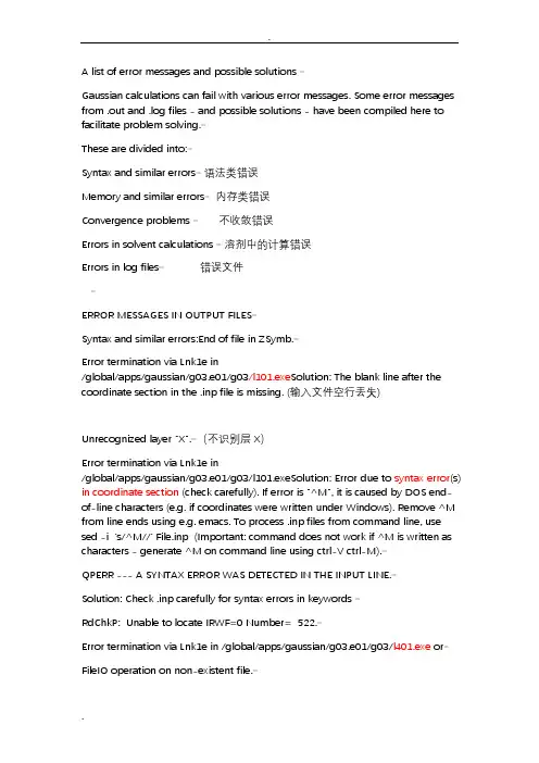
A list of error messages and possible solutions Gaussian calculations can fail with various error messages. Some error messages from .out and .log files - and possible solutions - have been compiled here to facilitate problem solving.These are divided into:Syntax and similar errors语法类错误Memory and similar errors内存类错误Convergence problems 不收敛错误Errors in solvent calculations 溶剂中的计算错误Errors in log files错误文件ERROR MESSAGES IN OUTPUT FILESSyntax and similar errors:End of file in ZSymb.Error termination via Lnk1e in/global/apps/gaussian/g03.e01/g03/l101.exe Solution: The blank line after the coordinate section in the .inp file is missing. (输入文件空行丢失)Unrecognized layer "X".(不识别层X)Error termination via Lnk1e in/global/apps/gaussian/g03.e01/g03/l101.exeSolution: Error due to syntax error(s) in coordinate section (check carefully). If error is "^M", it is caused by DOS end-of-line characters (e.g. if coordinates were written under Windows). Remove ^M from line ends using e.g. emacs. To process .inp files from command line, use sed -i 's/^M//' File.inp (Important: command does not work if ^M is written as characters - generate ^M on command line using ctrl-V ctrl-M).QPERR --- A SYNTAX ERROR WAS DETECTED IN THE INPUT LINE.Solution: Check .inp carefully for syntax errors in keywords RdChkP: Unable to locate IRWF=0 Number= 522.Error termination via Lnk1e in /global/apps/gaussian/g03.e01/g03/l401.exe orFileIO operation on non-existent file.[...] Error termination in NtrErr:NtrErr Called from FileIO.Solution: Operation on .chk file was specified (e.g.geom=check, opt=restart), but .chk was not found. Check that:%chk= was specifed in .inp.chk has the same name as .inp.chk is in the same directory as .inp run script transports .chk to temporary folder upon job start. Run scripts downloaded here should do this. The combination of multiplicity N and M electrons is impossible.(多重性)Error termination via Lnk1e in/global/apps/gaussian/g03.e01/g03/l301.exeSolution: Either the charge or the multiplicity of the molecule was not specified correctly in .inp.(电荷和多重性指定错误)Memory and similar errors: Out-of-memory error in routine RdGeom-1 (IEnd= 1200001 MxCore= 2500)Use %mem=N MW to provide the minimum amount of memory required to complete this stepError termination via Lnk1e in /global/apps/gaussian/g03.e01/g03/l101.exe orNot enough memory to run CalDSu, short by 1000000 words.Error termination via Lnk1e in /global/apps/gaussian/g03.e01/g03/l401.exe or[...] allocation failure: (表示配分失败)Error termination via Lnk1e in/global/apps/gaussian/g03.e01/g03/l1502.exe Solution: Specify more memoryin .inp (%mem=Nmb). Possibly, also increase pvmem value in run script. Especially solvent calculations can exhibit allocation failures and explicit amounts of memory should be specified.galloc: could not allocate memory.(无法分配内存)Solution: The %mem value in .inp is higher than pvmem value in run script. Increase pvmem or decrease %mem. Probably out of disk space(磁盘空间). Write error in NtrExt1 Solution: /scratch space is most likely full. Delete old files in temporary folder. Convergence problems: Density matrix is not changing but DIIS error= 1.32D-06 CofLast= 1.18D-02.(收敛问题)The SCF is confused. Error termination via Lnk1e in/global/apps/gaussian/g03.e01/g03/linda-exe/l502.exel Solution: Problem with DIIS. Turn it off completely, e.g. using SCF=qc, or partly by usingSCF=(maxconventionalcycles=N,xqc), where N is the number of steps DIIS should be used (see SCF keyword). Convergence criterion not met. SCF Done: E(RHF) = NNNNNNN A.U. after 129 cycles [...] Convergence failure -- run terminated. Error termination via Lnk1e in/global/apps/gaussian/g03.e01/g03/linda-exe/l502.exe Solution: One SCF cycle has a default of maximum 128 steps, and this was exceeded without convergence achieved. Possible solution: In the route section of input file, specify SCF=(MaxCycle=N), where N is the number of steps per SCF cycles. Alternatively, turn of DIIS (e.g. by SCF=qc) (see SCF keyword).Problem with the distance matrix.(距离矩阵)Error termination via Lnk1e in /pkg/gaussian/g03/l202.exe Solution: Try to restart optimization from a different input geometry. (重新不同几何异构体的输入优化)New curvilinear step not converged(新曲线步骤不收敛). Error imposing constraintsError termination via Lnk1e in /pkg/gaussian/g03/l103.exeSolution: Problem with constrained coordinates (e.g. in OPT=modredun calculation). Try to restart optimization from a slightly different input geometry. (一种稍微不同的输入几何)Optimization stopped. -- Number of steps exceeded, NStep= N[..] Error termination request processed by link 9999.Error termination via Lnk1e in /global/apps/gaussian/g03.e01/g03/l9999.exe Solution: Maximum number of optimization steps is twice the number of variables to be optimized. Try increasing the value by specifyingOPT=(MaxCycle=N) in .inp file, where N is the number of optimization steps (see OPT keyword). Alternatively, try to start optimization from different geometry.Errors in solvent calculations: AdVTs1: ISph= 2543 is engulfed by JSph= 2544but Ae( 2543) is not yet zero!Error termination via Lnk1e in/global/apps/gaussian/g03.e01/g03/l301.exe Solution: Problem is related to building of the cavity in solvent calculations(溶剂效应优化计算错误). One possible solution is to change the cavity(腔) model (default in g03 is UAO, can be changed by adding RADII keyword in section below coordinates inthe .inp file, e.g. RADII=UFF, see SCRF keyword).Hydrogen X has 2 bounds. Keep it explicit at all point on thepotential energy surface to get meaningful results.Solution: In UAO cavity model, spheres are placed on groups of atoms, with hydrogens assigned to the heavy atom, they are bound to. If assignment fails (e.g. because heavy atom-H bond is elongated), cavity building fails. Possible solutions: a) use cavity model that also assigns spheres to hydrogens (e.g. RADII=UFF) or b) Assign a sphere explicity on problematic H atom (use SPHEREONH=N, see SCRF keyword)ERROR MESSAGES IN LOGFILES =>> PBS: job killed: wall time N exceeded limit Msignal number 15 received. Solution: Job did not finish within specified wall time. Retrieve .out and .chk files from temporary folder /global/work/$USER/$JOB (or $PBS_JOBID) and restart calculation if possible (using e.g. opt=restart orscf=restart). cp: cannot stat $JOB.inp: No such file or directory Solution: The .inp file is not in the directory from where the job was submitted (or its name was misspelled during submission. If error reads: cp: cannot stat $JOB .inp .inp, the .inp file was submitted with extension).ntsnet: unable to schedule the minimum N workers Solution: The value of %N proc Linda=N in the .inp file is higher than the number of nodes asked for during submission. Make sure these values match.Connection refused [...] died without ever signing inSign in timed out after 0 worker connections. Did not reach minimum (N), shutting downSolution: Error appears if you run parallel calculations but did not add this file to your $HOME directory: .tsnet.config containing only the line: Tsnet.Node.lindarsharg: ssh (see also guidelines for submission). Density matrix is not changing but DIIS error - Suggested solutions1/- SCF=qc will probably solve the problem, albeit at a cost- Change the SCF converger to either SD, Quadratic or Fermi2/- lower the symmetry of optimize with and optimizewith the "nosymm" keywordI solved the problem using a variation on the first suggestion. Normally the scf took less than 80 cycles to converge. So i usedscf=(Maxconventionalcycles=100,xqc) which resulted in a good compromise between using scf=qc and optimisation speed. In the case of the DIIS error the scf always took more than 100 cycles before the error, so by addingscf=(Maxconventionalcycles=100,xqc) the scf switched to qc after 100 cycles in the standard DIIS mode.l9999错误是优化圈数不够,把out文件保存成gjf,修改后接着优化。
CCS问题解答[非常有实用价值]
问:在调试中,发现启动ccs时会弹出如下对话框
can't initialize target cpu:
error Ox80000200/-1073
fatal error during:ocs
bad target silicon revision number
please check your multi-processor configuration.
the number of devices in the JTAG scan path
must be correct for the silicon revision to be read
or,you may have selected the wrong DSP device driver
有谁遇到过这样的问题吗?请指教!
答:一种,如提示信息,你的CCS和你的JTAG版本不一致
一种,CCS和JA TG没问题,但没配置好,例如你只有一个目标DSP、配置却多于一个
最好能说明什么CCS、什么JTAG、什么DSP,否则就是TI的工程师也说不准可能是什么问题
JATG是个很乱的东西,各家就是自己的JTAG也往往前后不兼容,例如硬件bug除掉后修改了相应的JTAG 数据流、等
兼容的JTAG兼容到什么程度,只有各种片子都连了才知道。
这个工作量可想而知,碰到问题时、一般都晚了
总归,除非你有和被仿真芯片相一致的JTAG数据文件那么JTAG仿真就失去了起码的前提,JTAG的这种局限性很大,数据域测试这种局限性既普遍又难以在客户方定位。
chechcifAB类错误说明关于CIF检测中出现的A,B等类错误的说明,共8份----1-3关于CIF检测中出现的A,B等类错误的说明,共8份-1一般分为8类,分别为:# _0xx - general# _1xx - cell/symmetry# _2xx - adp-related# _3xx - intra geometry# _4xx - inter geometry# _5xx - coordination geometry# _6xx - void tests# _7xx – various test下面我们分几次把问题的简要说明翻译成献给大家,希望能对您有所帮助!_201 检测分子结构主体中各向同性的非氢原子,各向同性在通常的精修中并不常用,只是在处理无序是才用到。
_202 检测溶剂分子或阴离子中各向同性的非氢原子_211 检测主体分子的NPD ADP's 。
检测主体分子中各相异性参数中负值部分_212 检测溶剂或阴离子分子的NPD ADP's 。
检测溶剂或阴离子分子中各相异性参数中负值部_213 主体分子中ADP maximum/minimum 比例检测,较大的值意味着无序没有处理。
_214 溶剂或阴离子中ADP maximum/minimum 比例检测,较大的值意味着无序没有处理。
_220 检测主体结构非氢原子Ueq(max)/Ueq(Min)范围。
对比平常之大的比值发出警报。
太高或太低的值表明原子可能定错(i.e. Br versus Ag)_221 检测非主体结构非氢原子Ueq(max)/Ueq(Min)范围。
对比平常之大的比值发出警报_222 检测主体结构氢原子Ueq(max)/Ueq(Min)范围。
对比平常之大的比值发出警报_223 检测非主体结构氢原子Ueq(max)/Ueq(Min)范围。
对比平常之大的比值发出警报_230, _233 : Hirschfield 刚性键检查。

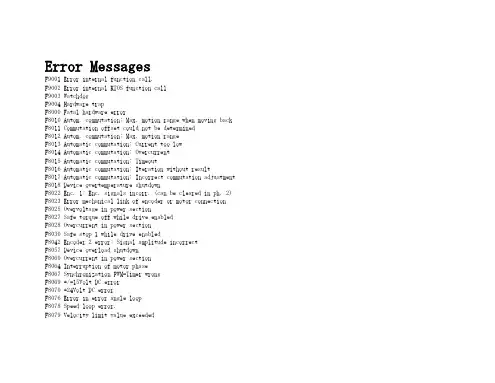
Error MessagesF9001 Error internal function call.F9002 Error internal RTOS function callF9003 WatchdogF9004 Hardware trapF8000 Fatal hardware errorF8010 Autom. commutation: Max. motion range when moving back F8011 Commutation offset could not be determinedF8012 Autom. commutation: Max. motion rangeF8013 Automatic commutation: Current too lowF8014 Automatic commutation: OvercurrentF8015 Automatic commutation: TimeoutF8016 Automatic commutation: Iteration without resultF8017 Automatic commutation: Incorrect commutation adjustment F8018 Device overtemperature shutdownF8022 Enc. 1: Enc. signals incorr. (can be cleared in ph. 2) F8023 Error mechanical link of encoder or motor connectionF8025 Overvoltage in power sectionF8027 Safe torque off while drive enabledF8028 Overcurrent in power sectionF8030 Safe stop 1 while drive enabledF8042 Encoder 2 error: Signal amplitude incorrectF8057 Device overload shutdownF8060 Overcurrent in power sectionF8064 Interruption of motor phaseF8067 Synchronization PWM-Timer wrongF8069 +/-15Volt DC errorF8070 +24Volt DC errorF8076 Error in error angle loopF8078 Speed loop error.F8079 Velocity limit value exceededF8091 Power section defectiveF8100 Error when initializing the parameter handlingF8102 Error when initializing power sectionF8118 Invalid power section/firmware combinationF8120 Invalid control section/firmware combinationF8122 Control section defectiveF8129 Incorrect optional module firmwareF8130 Firmware of option 2 of safety technology defectiveF8133 Error when checking interrupting circuitsF8134 SBS: Fatal errorF8135 SMD: Velocity exceededF8140 Fatal CCD error.F8201 Safety command for basic initialization incorrectF8203 Safety technology configuration parameter invalidF8813 Connection error mains chokeF8830 Power section errorF8838 Overcurrent external braking resistorF7010 Safely-limited increment exceededF7011 Safely-monitored position, exceeded in pos. DirectionF7012 Safely-monitored position, exceeded in neg. DirectionF7013 Safely-limited speed exceededF7020 Safe maximum speed exceededF7021 Safely-limited position exceededF7030 Position window Safe stop 2 exceededF7031 Incorrect direction of motionF7040 Validation error parameterized - effective thresholdF7041 Actual position value validation errorF7042 Validation error of safe operation modeF7043 Error of output stage interlockF7050 Time for stopping process exceeded8.3.15 F7051 Safely-monitored deceleration exceeded (159)8.4 Travel Range Errors (F6xxx) (161)8.4.1 Behavior in the Case of Travel Range Errors (161)8.4.2 F6010 PLC Runtime Error (162)8.4.3 F6024 Maximum braking time exceeded (163)8.4.4 F6028 Position limit value exceeded (overflow) (164)8.4.5 F6029 Positive position limit exceeded (164)8.4.6 F6030 Negative position limit exceeded (165)8.4.7 F6034 Emergency-Stop (166)8.4.8 F6042 Both travel range limit switches activated (167)8.4.9 F6043 Positive travel range limit switch activated (167)8.4.10 F6044 Negative travel range limit switch activated (168)8.4.11 F6140 CCD slave error (emergency halt) (169)8.5 Interface Errors (F4xxx) (169)8.5.1 Behavior in the Case of Interface Errors (169)8.5.2 F4001 Sync telegram failure (170)8.5.3 F4002 RTD telegram failure (171)8.5.4 F4003 Invalid communication phase shutdown (172)8.5.5 F4004 Error during phase progression (172)8.5.6 F4005 Error during phase regression (173)8.5.7 F4006 Phase switching without ready signal (173)8.5.8 F4009 Bus failure (173)8.5.9 F4012 Incorrect I/O length (175)8.5.10 F4016 PLC double real-time channel failure (176)8.5.11 F4017 S-III: Incorrect sequence during phase switch (176)8.5.12 F4034 Emergency-Stop (177)8.5.13 F4140 CCD communication error (178)8.6 Non-Fatal Safety Technology Errors (F3xxx) (178)8.6.1 Behavior in the Case of Non-Fatal Safety Technology Errors (178)8.6.2 F3111 Refer. missing when selecting safety related end pos (179)8.6.3 F3112 Safe reference missing (179)8.6.4 F3115 Brake check time interval exceeded (181)Troubleshooting Guide | Rexroth IndraDrive Electric Drivesand ControlsI Bosch Rexroth AG VII/XXIITable of ContentsPage8.6.5 F3116 Nominal load torque of holding system exceeded (182)8.6.6 F3117 Actual position values validation error (182)8.6.7 F3122 SBS: System error (183)8.6.8 F3123 SBS: Brake check missing (184)8.6.9 F3130 Error when checking input signals (185)8.6.10 F3131 Error when checking acknowledgment signal (185)8.6.11 F3132 Error when checking diagnostic output signal (186)8.6.12 F3133 Error when checking interrupting circuits (187)8.6.13 F3134 Dynamization time interval incorrect (188)8.6.14 F3135 Dynamization pulse width incorrect (189)8.6.15 F3140 Safety parameters validation error (192)8.6.16 F3141 Selection validation error (192)8.6.17 F3142 Activation time of enabling control exceeded (193)8.6.18 F3143 Safety command for clearing errors incorrect (194)8.6.19 F3144 Incorrect safety configuration (195)8.6.20 F3145 Error when unlocking the safety door (196)8.6.21 F3146 System error channel 2 (197)8.6.22 F3147 System error channel 1 (198)8.6.23 F3150 Safety command for system start incorrect (199)8.6.24 F3151 Safety command for system halt incorrect (200)8.6.25 F3152 Incorrect backup of safety technology data (201)8.6.26 F3160 Communication error of safe communication (202)8.7 Non-Fatal Errors (F2xxx) (202)8.7.1 Behavior in the Case of Non-Fatal Errors (202)8.7.2 F2002 Encoder assignment not allowed for synchronization (203)8.7.3 F2003 Motion step skipped (203)8.7.4 F2004 Error in MotionProfile (204)8.7.5 F2005 Cam table invalid (205)8.7.6 F2006 MMC was removed (206)8.7.7 F2007 Switching to non-initialized operation mode (206)8.7.8 F2008 RL The motor type has changed (207)8.7.9 F2009 PL Load parameter default values (208)8.7.10 F2010 Error when initializing digital I/O (-> S-0-0423) (209)8.7.11 F2011 PLC - Error no. 1 (210)8.7.12 F2012 PLC - Error no. 2 (210)8.7.13 F2013 PLC - Error no. 3 (211)8.7.14 F2014 PLC - Error no. 4 (211)8.7.15 F2018 Device overtemperature shutdown (211)8.7.16 F2019 Motor overtemperature shutdown (212)8.7.17 F2021 Motor temperature monitor defective (213)8.7.18 F2022 Device temperature monitor defective (214)8.7.19 F2025 Drive not ready for control (214)8.7.20 F2026 Undervoltage in power section (215)8.7.21 F2027 Excessive oscillation in DC bus (216)8.7.22 F2028 Excessive deviation (216)8.7.23 F2031 Encoder 1 error: Signal amplitude incorrect (217)VIII/XXII Bosch Rexroth AG | Electric Drivesand ControlsRexroth IndraDrive | Troubleshooting GuideTable of ContentsPage8.7.24 F2032 Validation error during commutation fine adjustment (217)8.7.25 F2033 External power supply X10 error (218)8.7.26 F2036 Excessive position feedback difference (219)8.7.27 F2037 Excessive position command difference (220)8.7.28 F2039 Maximum acceleration exceeded (220)8.7.29 F2040 Device overtemperature 2 shutdown (221)8.7.30 F2042 Encoder 2: Encoder signals incorrect (222)8.7.31 F2043 Measuring encoder: Encoder signals incorrect (222)8.7.32 F2044 External power supply X15 error (223)8.7.33 F2048 Low battery voltage (224)8.7.34 F2050 Overflow of target position preset memory (225)8.7.35 F2051 No sequential block in target position preset memory (225)8.7.36 F2053 Incr. encoder emulator: Pulse frequency too high (226)8.7.37 F2054 Incr. encoder emulator: Hardware error (226)8.7.38 F2055 External power supply dig. I/O error (227)8.7.39 F2057 Target position out of travel range (227)8.7.40 F2058 Internal overflow by positioning input (228)8.7.41 F2059 Incorrect command value direction when positioning (229)8.7.42 F2063 Internal overflow master axis generator (230)8.7.43 F2064 Incorrect cmd value direction master axis generator (230)8.7.44 F2067 Synchronization to master communication incorrect (231)8.7.45 F2068 Brake error (231)8.7.46 F2069 Error when releasing the motor holding brake (232)8.7.47 F2074 Actual pos. value 1 outside absolute encoder window (232)8.7.48 F2075 Actual pos. value 2 outside absolute encoder window (233)8.7.49 F2076 Actual pos. value 3 outside absolute encoder window (234)8.7.50 F2077 Current measurement trim wrong (235)8.7.51 F2086 Error supply module (236)8.7.52 F2087 Module group communication error (236)8.7.53 F2100 Incorrect access to command value memory (237)8.7.54 F2101 It was impossible to address MMC (237)8.7.55 F2102 It was impossible to address I2C memory (238)8.7.56 F2103 It was impossible to address EnDat memory (238)8.7.57 F2104 Commutation offset invalid (239)8.7.58 F2105 It was impossible to address Hiperface memory (239)8.7.59 F2110 Error in non-cyclical data communic. of power section (240)8.7.60 F2120 MMC: Defective or missing, replace (240)8.7.61 F2121 MMC: Incorrect data or file, create correctly (241)8.7.62 F2122 MMC: Incorrect IBF file, correct it (241)8.7.63 F2123 Retain data backup impossible (242)8.7.64 F2124 MMC: Saving too slowly, replace (243)8.7.65 F2130 Error comfort control panel (243)8.7.66 F2140 CCD slave error (243)8.7.67 F2150 MLD motion function block error (244)8.7.68 F2174 Loss of motor encoder reference (244)8.7.69 F2175 Loss of optional encoder reference (245)Troubleshooting Guide | Rexroth IndraDrive Electric Drivesand Controls| Bosch Rexroth AG IX/XXIITable of ContentsPage8.7.70 F2176 Loss of measuring encoder reference (246)8.7.71 F2177 Modulo limitation error of motor encoder (246)8.7.72 F2178 Modulo limitation error of optional encoder (247)8.7.73 F2179 Modulo limitation error of measuring encoder (247)8.7.74 F2190 Incorrect Ethernet configuration (248)8.7.75 F2260 Command current limit shutoff (249)8.7.76 F2270 Analog input 1 or 2, wire break (249)8.7.77 F2802 PLL is not synchronized (250)8.7.78 F2814 Undervoltage in mains (250)8.7.79 F2815 Overvoltage in mains (251)8.7.80 F2816 Softstart fault power supply unit (251)8.7.81 F2817 Overvoltage in power section (251)8.7.82 F2818 Phase failure (252)8.7.83 F2819 Mains failure (253)8.7.84 F2820 Braking resistor overload (253)8.7.85 F2821 Error in control of braking resistor (254)8.7.86 F2825 Switch-on threshold braking resistor too low (255)8.7.87 F2833 Ground fault in motor line (255)8.7.88 F2834 Contactor control error (256)8.7.89 F2835 Mains contactor wiring error (256)8.7.90 F2836 DC bus balancing monitor error (257)8.7.91 F2837 Contactor monitoring error (257)8.7.92 F2840 Error supply shutdown (257)8.7.93 F2860 Overcurrent in mains-side power section (258)8.7.94 F2890 Invalid device code (259)8.7.95 F2891 Incorrect interrupt timing (259)8.7.96 F2892 Hardware variant not supported (259)8.8 SERCOS Error Codes / Error Messages of Serial Communication (259)9 Warnings (Exxxx) (263)9.1 Fatal Warnings (E8xxx) (263)9.1.1 Behavior in the Case of Fatal Warnings (263)9.1.2 E8025 Overvoltage in power section (263)9.1.3 E8026 Undervoltage in power section (264)9.1.4 E8027 Safe torque off while drive enabled (265)9.1.5 E8028 Overcurrent in power section (265)9.1.6 E8029 Positive position limit exceeded (266)9.1.7 E8030 Negative position limit exceeded (267)9.1.8 E8034 Emergency-Stop (268)9.1.9 E8040 Torque/force actual value limit active (268)9.1.10 E8041 Current limit active (269)9.1.11 E8042 Both travel range limit switches activated (269)9.1.12 E8043 Positive travel range limit switch activated (270)9.1.13 E8044 Negative travel range limit switch activated (271)9.1.14 E8055 Motor overload, current limit active (271)9.1.15 E8057 Device overload, current limit active (272)X/XXII Bosch Rexroth AG | Electric Drivesand ControlsRexroth IndraDrive | Troubleshooting GuideTable of ContentsPage9.1.16 E8058 Drive system not ready for operation (273)9.1.17 E8260 Torque/force command value limit active (273)9.1.18 E8802 PLL is not synchronized (274)9.1.19 E8814 Undervoltage in mains (275)9.1.20 E8815 Overvoltage in mains (275)9.1.21 E8818 Phase failure (276)9.1.22 E8819 Mains failure (276)9.2 Warnings of Category E4xxx (277)9.2.1 E4001 Double MST failure shutdown (277)9.2.2 E4002 Double MDT failure shutdown (278)9.2.3 E4005 No command value input via master communication (279)9.2.4 E4007 SERCOS III: Consumer connection failed (280)9.2.5 E4008 Invalid addressing command value data container A (280)9.2.6 E4009 Invalid addressing actual value data container A (281)9.2.7 E4010 Slave not scanned or address 0 (281)9.2.8 E4012 Maximum number of CCD slaves exceeded (282)9.2.9 E4013 Incorrect CCD addressing (282)9.2.10 E4014 Incorrect phase switch of CCD slaves (283)9.3 Possible Warnings When Operating Safety Technology (E3xxx) (283)9.3.1 Behavior in Case a Safety Technology Warning Occurs (283)9.3.2 E3100 Error when checking input signals (284)9.3.3 E3101 Error when checking acknowledgment signal (284)9.3.4 E3102 Actual position values validation error (285)9.3.5 E3103 Dynamization failed (285)9.3.6 E3104 Safety parameters validation error (286)9.3.7 E3105 Validation error of safe operation mode (286)9.3.8 E3106 System error safety technology (287)9.3.9 E3107 Safe reference missing (287)9.3.10 E3108 Safely-monitored deceleration exceeded (288)9.3.11 E3110 Time interval of forced dynamization exceeded (289)9.3.12 E3115 Prewarning, end of brake check time interval (289)9.3.13 E3116 Nominal load torque of holding system reached (290)9.4 Non-Fatal Warnings (E2xxx) (290)9.4.1 Behavior in Case a Non-Fatal Warning Occurs (290)9.4.2 E2010 Position control with encoder 2 not possible (291)9.4.3 E2011 PLC - Warning no. 1 (291)9.4.4 E2012 PLC - Warning no. 2 (291)9.4.5 E2013 PLC - Warning no. 3 (292)9.4.6 E2014 PLC - Warning no. 4 (292)9.4.7 E2021 Motor temperature outside of measuring range (292)9.4.8 E2026 Undervoltage in power section (293)9.4.9 E2040 Device overtemperature 2 prewarning (294)9.4.10 E2047 Interpolation velocity = 0 (294)9.4.11 E2048 Interpolation acceleration = 0 (295)9.4.12 E2049 Positioning velocity >= limit value (296)9.4.13 E2050 Device overtemp. Prewarning (297)Troubleshooting Guide | Rexroth IndraDrive Electric Drivesand Controls| Bosch Rexroth AG XI/XXIITable of ContentsPage9.4.14 E2051 Motor overtemp. prewarning (298)9.4.15 E2053 Target position out of travel range (298)9.4.16 E2054 Not homed (300)9.4.17 E2055 Feedrate override S-0-0108 = 0 (300)9.4.18 E2056 Torque limit = 0 (301)9.4.19 E2058 Selected positioning block has not been programmed (302)9.4.20 E2059 Velocity command value limit active (302)9.4.21 E2061 Device overload prewarning (303)9.4.22 E2063 Velocity command value > limit value (304)9.4.23 E2064 Target position out of num. range (304)9.4.24 E2069 Holding brake torque too low (305)9.4.25 E2070 Acceleration limit active (306)9.4.26 E2074 Encoder 1: Encoder signals disturbed (306)9.4.27 E2075 Encoder 2: Encoder signals disturbed (307)9.4.28 E2076 Measuring encoder: Encoder signals disturbed (308)9.4.29 E2077 Absolute encoder monitoring, motor encoder (encoder alarm) (308)9.4.30 E2078 Absolute encoder monitoring, opt. encoder (encoder alarm) (309)9.4.31 E2079 Absolute enc. monitoring, measuring encoder (encoder alarm) (309)9.4.32 E2086 Prewarning supply module overload (310)9.4.33 E2092 Internal synchronization defective (310)9.4.34 E2100 Positioning velocity of master axis generator too high (311)9.4.35 E2101 Acceleration of master axis generator is zero (312)9.4.36 E2140 CCD error at node (312)9.4.37 E2270 Analog input 1 or 2, wire break (312)9.4.38 E2802 HW control of braking resistor (313)9.4.39 E2810 Drive system not ready for operation (314)9.4.40 E2814 Undervoltage in mains (314)9.4.41 E2816 Undervoltage in power section (314)9.4.42 E2818 Phase failure (315)9.4.43 E2819 Mains failure (315)9.4.44 E2820 Braking resistor overload prewarning (316)9.4.45 E2829 Not ready for power on (316)。
Record the result.Place the used test strip and lancet in Before continuing, review these tips for getting a good blood drop.Increasing the blood flow in the finger will help you get a good drop of blood, so keep in mind these tips:• W arm the hand. Have the patienthold it under his or her arm, use a hand warmer, and/or wash with warm water.• H ave the patient let that arm hang by his or her side.• M assage the finger from its e these techniques until the fingertip has good color.CoaguChek ®XS SystemInstallIng BatterIes & setuptgettIng startedtsettIng date and tImetpreparIng for a testttestIngtOpen the battery compartment on the back of the meter.Insert 4 AAA batteries according to the diagram inside the battery compartment.1. o pen Compartment2. Insert Batteries• CoaguChek XS Meter • Container of test strips • Test strip code chip • CoaguChek lancetThe code number on the test strip container and the code chip must match.Each box of test strips comes with a matching code chip. Every time you open a new box of test strips, you must replace the code chip.Make sure the meter is off.With the code number facing up,insert the code chip into the code chip slot until it snaps into place. Have the patient wash his or herhands in warm, soapy water. Or, clean the fingertip with an alcohol wipe. Make sure the fingertip is thoroughly dry.If the meter is not already in Setupmode, pressThe date format flashes in the upper right corner.and symbols on the display appear correctly.Take a test strip out of the container.Close the container tightly.Do not open a vial of test strips or touch a test strip with wet hands or wet gloves. This may damage the test strips.You have 10 minutes to use a test strip once you remove it from the container.Slide the test strip into the test strip guide in the direction of the arrows until it stops.The meter powers on.The code number of the inserted code chip flashes on the display.1. get ready2. Insert test stripConfirm that the number displayed sure that the correct code chip is inserted. If you are using the correct code chip but the numbers don’t match, see the User Manual.An hourglass appears as the meter warms the test strip. A flashing test strip and blood drop appear when ready for a sample.You have 180 seconds to apply blood to the test strip.Twist the protective cap off the CoaguChek lancet.Massage the finger until you see increased color in the fingertip.Keeping the hand down, press the tip of the lancet firmly against the side of the fingertip. Press the blue trigger button.Gently squeeze from the base of the finger to develop a hanging drop of blood.Find the target area on the test strip. You can dose from the side or top. See the User Manual for more information.Within 15 seconds of sticking the fingertip , apply the blood to the target area on the test strip.Hold the blood drop to the test strip until you hear a beep. The flashing blood drop symbol will disappear.do not add more blood to the test strip. do not touch the test strip. The result appears in about 1 minute.3. match Code4. Collect sample5. apply sampleto change the month then to change the day thenThe time format flashes in the upper left corner.follow these steps to get started using the meter:1. W atch the CoaguChek XS System Video . It will help you get comfortable with the CoaguChek XS Meter and the testing procedure.2. W ith this CoaguChek XS System Getting Started guide by the meter, follow the steps to perform your first test.then, as necessary, refer to the user manual:The CoaguChek XS System User Manual is a comprehensive guide to the meter and test strips. It is designed to provide answers to your questions about the meter’s operation and use.This is a CLIA waived system.6. record result7. Clean upRight after you insert the batteries, you’ll need to set the date and time.The date and time settings are important. Each time you run a test, the meter compares its date with the test strip’s expiration date. If the test strip is expired, the meter displays an error message and prevents you from running a test.Whenever you put batteries in the meter, it automatically goes to Setup mode (where you set the date and time). You can also go to Setup mode at any time by pressing the SET button Note: If during testing the meter displays an error message, refer to the Error Messages section of the User Manual for an explanation and steps on how to proceed.getting started1. gather Items2. match Code3. Insert Code Chip4. Wash Hands0123COAGUCHEK is a trademark of Roche. ©2006-2009 Roche Diagnostics. All rights reserved.Manufactured for and distributed in the U.S.A. by: Roche Diagnostics 9115 Hague Road Indianapolis, IN 46256 Roche Diagnostics GmbH Sandhofer Strasse 116 68305 Mannheim Germany0 4837983001 (03) 2009-09 U S A。
1.问:在使用checkCIF service进行投稿前检查时,出现了如下的几个alert,想请教该怎么改进。
尤其是两个C类问题!Alert level CPLAT125_ALERT_4_C No _symmetry_space_group_name_Hall Given ....... ? PLAT790_ALERT_4_C Centre of Gravity not Within Unit Cell: Resd. # 1C16 H24 O3--------------------------------------------------------------------------------Alertlevel GPLAT199_ALERT_1_G Check the Reported _cell_measurement_temperature 273 K PLAT200_ALERT_1_G Check the Reported _diffrn_ambient_temperature 273 K PLAT380_ALERT_4_G Check Incorrectly? Oriented X(sp2)-Methyl Moiety C18-------------------------------------------------------------------------------- 0 ALERTlevel A = In general: serious problem0 ALERT level B = Potentially serious problem2 ALERT level C = Check and explain3 ALERT level G = General alerts; check2 ALERT type 1 CIF construction/syntax error, inconsistent or missing data0 ALERT type 2 Indicator that the structure model may be wrong or deficient0 ALERT type 3 Indicator that the structure quality may be low3 ALERT type4 Improvement, methodology, query or suggestion0 ALERT type 5 Informative message, checkPLAT125_ALERT_4_C No _symmetry_space_group_name_Hall Given ....... ?答:在CIF文件中加_symmetry_space_group_name_Hall具体如下:1)是加在_symmetry_space_group_name_H-M 之后例如:_symmetry_space_group_name_H-M 'P 21/c'_symmetry_space_group_name_Hall '-P 2ybc'2)该符号在checkcif后的网页的左上方找.PLAT790_ALERT_4_C Centre of Gravity not Within Unit Cell: Resd. # 1C16 H24 O3分子重心不在单胞内, 要平移或对称操作后, 使得大部分原子的分数坐标都在单胞内,即大部分原子的坐标都是正分数,而不是1.xxx或-0.xxxx具体可在.ins中加move 指令或在xp中用sgen.操作完毕后要重新修正到收敛,产生新的.cif.alert G可不理.第一个加上空间群一列第二个ms分子没在单胞内移动2.cif A错误PLAT307_ALERT_2_A Isolated Metal Atom (Unusual !) ................ Pb1_dPLAT307_ALERT_2_A Isolated Metal Atom (Unusual !) ................ Pb1_i 有没有见过这样的A错误A 错误解释This test reports on metal atoms that are not bonded or at coordinationdistance of other atoms. Isolated ions are very unusual (or non-existent ?)解决方案:把重金属删除后,重新再找。
AntiSpamming2850垃圾短信监控平台2850安装指南目录目录C 安装和配置常用外购软件......................................................................................................... C-1C.1 手动安装VCS ............................................................................................................................................................ C-1C.1.1 安装VCS 4.1 MP3 .......................................................................................................................................... C-1C.1.2 安装VCS 4.1 MP4 .......................................................................................................................................... C-7C.1.3 安装VCS 4.1MP4 RP3................................................................................................................................ C-13C.1.4 配置VCS......................................................................................................................................................... C-13C.2 自动安装VCS .......................................................................................................................................................... C-18C.2.1 USM安装顺序说明....................................................................................................................................... C-18C.2.2 登录USM服务器 ......................................................................................................................................... C-18C.2.3 添加软件源 ..................................................................................................................................................... C-19C.2.4 添加软件源许可证........................................................................................................................................ C-20C.2.5 定制安装模板................................................................................................................................................. C-21C.2.6 部署安装任务................................................................................................................................................. C-22C.2.7 安装后配置 ..................................................................................................................................................... C-23C.2.8 安装后检验 ..................................................................................................................................................... C-25C.2.9 卸载VCS......................................................................................................................................................... C-25C.3 安装数据库软件Agent........................................................................................................................................... C-26C.4 安装VCS客户端..................................................................................................................................................... C-26C.5 安装UltraPath for Linux......................................................................................................................................... C-26C.5.1 安装UltraPath for Linux应用程序 ........................................................................................................... C-27C.5.2 卸载UltraPath for Linux .............................................................................................................................. C-28C.6 安装DB2客户端......................................................................................................................错误!未定义书签。
Checking SCADE Models for Correct Usage of PhysicalUnitsRupert Schlick1, Wolfgang Herzner1, Thierry Le Sergent21 ARC Seibersdorf research, division Information Technology{rupert.schlick, wolfgang.herzner}@arcs.ac.at2 Esterel Technologiesthierry.lesergent@Abstract. Mismatches of units and of scales of values in physical calculationsare disastrous, but rather common, in the development of embedded controlsystems. They can be as plain as mixing feet and metres, or as hidden as awrong exponent in a complex calculation formula. These errors can be found bya checking algorithm, following some simple rules, if information on the unitsof the used variables is provided. This paper describes a developer friendly ap-proach of providing this checking functionality in SCADE, a model-basedgraphical development tool for safety-critical embedded applications.1Key words: physical units, safety, verification, error detection, dependable em-bedded systems, model based software development, SCADE, DECOS1IntroductionControl systems usually have to deal with physical quantities like time, tempera-ture, length, speed or electrical current. Simply using numeric standard data types like real or float paves the way for typical programming errors like mixing scales (e.g. adding seconds and milliseconds), using wrong operators (v : m*s), swapping oper-ands (v : s/m) etc. The most well known/notorious example is the loss of the mars climate orbiter in 1999 [11], lost due to a unit conversion mistake not found during testing. But earth bound safety critical applications are prone to this family of errors as well.While several methods and tools are available for various programming languages to cope with such problems (see section 5), for data-flow oriented modelling lan-guages like Simulink [17] or SCADE [13], which are increasingly used in the domain of embedded systems, this is less the case. In particular, SCADE is especially appro-priate for development of safety-critical applications, due to its strict temporal execu-tion model, various included testing and verification tools like a model checker and a qualified C-code generator. Since in DECOS, which aims at development support of1 This work is partially funded by DECOS (Dependable Embedded COmponents and Systems), an integrated project funded by the EU within priority “Information Society Technologies (IST)” in the sixth EU framework programme (contract no. FP6-511 764).distributed embedded real-time systems of up to highest criticality, SCADE is an important part of the DECOS tool chain, it was decided to develop a SCADE exten-sion which allows a developer to check its model for dimensional or physical unit errors. Since this is done at modelling time and prior to code generation, it does not affect runtime performance.Therefore, this paper is structured as follows. The next section presents the con-cepts of a general approach, based on SI, the international system of physical units, and a special notation. Section 3 introduces SCADE shortly, and describes how this approach is implemented for SCADE, while section 4 gives some application exam-ples. The last two sections address related work and draw a conclusion, respectively. 2General ApproachThis section first gives a short terminology introduction and then describes the princi-pal rules applied in automatic unit checking at development-time.2.1The SI Unit System and Unit RepresentationPhysical quantities have a dimension; each dimension can be measured in multiple units. A unit system defines units for a set of mutually independent dimensions. These are the base units, all other units can be derived from them (giving derived units) by (multiple) multiplication and division of the base units.The SI unit system [14] is the standardized unit system most widely used in engi-neering today. SI base units are kilograms (kg), meters (m), seconds (s), ampere (A), Kelvin (K), mole (mol) and candela (cd). The remainder of this document is based on the SI unit system unless noted otherwise.Taking the SI units into consideration, it is fairly natural to represent a physical unit as a 7-dimensional vector, where each element denotes the exponent of the re-spective base unit in the given order. So, kg is denoted by [1,0,0,0,0,0,0], and s by [0,0,1,0,0,0,0]. Consequently, derived units are represented by vectors with more than one element different from 0; for instance:(1) In the rest of the paper, this notation will be simply referred as unit representation, synonymously with unit.2.2Rules for Operating on Physical UnitsIn scientific work and engineering, dimensional analysis and the unit-factor method are commonly used to ensure the correctness of equations and calculations.The following rules are basically the rules for dimensional analysis, adapted for use in computer programs and extended with some issues useful in control systems.Basic Rules For the four basic arithmetical operations, the following rules apply:•Addition and subtraction is allowed only for values with identical vectors. •Multiplication gives a new unit. Base unit exponents are calculated by adding the respective base unit exponents from the multiplicands.•Division gives a new unit. Base unit exponents are calculated by subtracting the divisors base unit exponents from the dividends exponents.Power is derived from multiplication – base unit exponents are multiplied by the power exponent.Root, as inverse function to power, results in the unit exponents divided by the root base. If the exponents are not divisible without remainder, the operation is not al-lowed. (In theory rational exponents are possible in intermediate results, but for the sake of brevity such details are not addressed here.)More Rules Functions like logarithm, exponentiation, or the trigonometric functions operate only on dimensionless numbers.2 Operators typically used in programming environments should also be supported. They can be grouped as follows: •Decision operators: all possible outputs of if and case must have the same unit. •Comparison operators: only quantities with identical units can be compared. •Composite data types: arithmetical operations only operate on basic data types, units of the basic data type are preserved through composition and decomposition. •Temporal operators (SCADE specific): simply preserve the unit of their inputs. For vector and matrix operations, similar rules to the ones for the base calculation methods apply. An important aspect is that a scalar and a vector with the same dimen-sion definitely do not have the same dimension as a whole (see also next clause).Exotic Rules There are issues with units being (formally) the same for different dimensions as well as the general topic of dimensionless units and numbers.Ambiguous Units Due to the use of a scalar form for the notation of units, situations can occur where the same unit name applies for two or more physical quantities. One example for this situation is Newton metres. It can measure both work and torque (See formulas 2 and 3). In correct dimensional analysis, work is the scalar product of two vector quantities - force and the distance over which it moves, resulting in a sca-lar value; torque is the vector product of the same quantities force and the length of the lever.The usual representation of units looses this information whether a quantity is a vector or not, therefore the dimensional analysis based on this unit check is some-times incomplete.2 These functions can be expressed as power series, where ascending powers of the argument are summed up. Adding values with different dimension exponents would break the basic rules and therefore the argument must be dimensionless.(2) (3)Despite the fact that torque is formally a vector, it is often feasible and efficient to treat it as a scalar during calculation, e.g. because all relevant axes are parallel any-way.Since energy and torque are units that are rather frequent in embedded and espe-cially automotive applications, it seems desirable to have a means to distinguish be-tween the two cases even when no vectors are used for calculations.A workaround to achieve this is to introduce an additional unit “radial meter” m r used when a radius is used in conjunction with tangential forces and other physical values. With it, the two units now become Nm r = m r m kg/s 2, and J = m 2 kg/s 2. m r can be modelled as an additional unit in the vector and should be used consis-tently for all related units like angular velocity. If a lever length is used in a calcula-tion, it must have m r as unit. All calculation rules apply to this new unit as well as for the original seven SI units. When torque is treated as a three dimensional vector, this is not necessary, although there may be other but similar issues.In general, dimensional analysis can be complemented by orientational analysis, checking a formula for errors in spatial orientation [15, 16]. Support for spatial di-mensions and orientational analysis would address the loss of information mentioned above and possibly will be added later on, but is out of the scope of this paper Dimensionless UnitsThere are two dimensionless derived SI units:(4)In many cases, it is desirable for readability to preserve these “units”. A simple solu-tion is to make use of the “radial meter” introduced above: rad = m/m r , and sr = m 2/mr 2.This avoids cancelling down the unit in the fraction and still gives sensible results. For example, multiplying torque with the rotational angle it is applied for yields the accomplished work.Dimensionless Numbers There are a lot of dimensionless physical values in various application areas, especially in fluid dynamics. Sometimes it is helpful to keep the information about the quantity being measured by putting the same units in both the numerator and denominator as for radians above .Generalized support for this would go beyond the scope of the drafted checking method, particularly because the technique of non-dimensionalization is especiallyused in number crunching and fluid dynamics, but little in the physics used in embed-ded control.A group of special cases of dimensionless numbers are logarithmically scaled ra-tios like dB. Some of them, like decibel microvolts (dBµV), are used in technical applications. In fact, they are dimensionless and if the represented quantity is needed for calculations, the value needs to be “delogarithmized” and multiplied with the base value (e.g. 1 µV for dBµV). Then the resulting value is a dimensioned value that can be checked for consistent units use as described above.2.3ScalingAlong with the SI units, a set of SI prefixes is defined. They are representing factors in steps of 1000 ranging from 10-24 – 1024 as well as the factors 10-2, 10-1, 10 and 100.The factor 10 can be modelled as an additional “unit” to represent the SI prefix in the same way as the seven SI units with the same rules for checking consistency. Only the root function behaves different, since it is valid to draw a root even if the exponent is not divisible by the root’s base; for a unit exponent, this would be an error. The resulting scaling exponent would be a fractional instead of an integer number as shown in the example below:(5) The 3101 part must be included in a free scaling factor (see “Odd Scaling Factors” below), part of the unit information only kept for analysis.Normalising and other conversion can be done by multiplication with dimen-sionless constants of a “scaled value” of 1, as 1000 milli (10-3) or 1/1000 kilo (103). Odd Scaling FactorsDistances, Weights, Areas and Volumes Especially for distances, weights, areas and volumes exists a multitude of units outside of the SI system (usually old, pre-SI units) some of which are (still) widely used in some regions (e.g. US customary units) or working areas (oil barrels, gold ounces, …). All of these have in common that they are a simple factor larger or smaller than the corresponding SI units. For scaling fac-tors, the basic calculation rules are adapted.Angles Angles differ from other units due to their periodicity. But since sensors may deliver angles like for torsion or rotational position in any range, it appears reasonable to allow signed values outside the circle range without any special consideration.2.4Absolute and Relative Values and Zero Point TranslationMost of the physical values covered above are always “relative” values. Nonetheless, at least one commonly used physical value is either relative or absolute: temperature.A data type can be marked as “absolute”. This means certain rules for calculations apply and they can have a zero point offset. At the moment, this is only aimed at temperatures but may be found useful for other units as well. In short, absolute (x a ) and relative (x r ) types of the same dimension can be combined as follows:• a r a x x ±x →: offset value stays the same• r a a x x x →−: offset value must be identical, result is relative and has no offset Other addition/subtraction expressions over absolute values are invalid.2.5 Extended Unit RepresentationAccording to the previous, the 7-dimensional unit representation introduced in 2.1 should be extended for•distinction between m and m r , •representing the scaling exponent relative to the dimension’s unit scale, •representing an “odd” scaling factor for non SI-units or “rooting” results, •marking of “absolute” values • offset for absolute values .3 Solution/Application in SCADEAfter a short introduction to SCADE, this section describes how the concepts and rules discussed before are implemented in SCADE.3.1 About SCADESCADE (the Safety Critical Application Development Environment) is both a nota-tion and a toolset that was specifically developed to describe and implement safety critical systems for application domains such as aeronautics or automobile. The SCADE notation includes both block diagrams 3 and safe state machines, giving a rigorous description of the complete behaviour of the software [8]. It has been for-mally defined and it has the following characteristics that are key in the targeted ap-plication domain, i.e. the development of safety critical systems:•Strong typing • Explicit initialization of data flows •Explicit management of time (delays, clocks, etc) •Simple expression of concurrency (data dependencies) • Deterministic execution3 Examples of block diagrams are shown in Figures 3 and 5.In SCADE, a node (which we can also call a “block”) performs logically atomic com-putations, providing deterministic output values corresponding to a given set of input values, according to the previous memorized state. Nodes can use other nodes as shown in figure 5, the root node taking its inputs from the environment. Feedback loops are handled in a simple way thanks to the time operators (delay). Recursion is forbidden.The computation is often triggered by a periodic clock (although it need not be), after inputs are sampled from the environment and hold.The SCADE toolset supports a model-driven paradigm in which the SCADE model is the software specification. Verification activities are supported by a combi-nation of three different tools [2, 5]:•The SCADE Suite Simulator supports interactive or batch simulation of a SCADE model, for both data flows and safe state machines.•The SCADE Suite Model Test Coverage (MTC) tool is used to measure the cover-age of the SCADE model with respect to a given requirements-based test suite. •The SCADE Suite Design Verifier (DV) supports corner bug detection and formal verification of safety requirements.The SCADE toolset also provides an API to access all the details of a model from tcl scripts. This allows in a simple way development of utilities to check for example that a model conforms to some user specific methodological rules.The C code generator is certified with respect to DO-178B level A (avionics) [6] and IEC 61508 up to Safety Integrity Level (SIL) 4 (other industrial domains, such as automotive or railways), thus providing a guarantee that the generated code is correct with respect to the model.3.2ImplementationThe Units-Check package for SCADE consists of:1.The units-check function itself, fully integrated into the SCADE user interface2.A SCADE library containing•predefined units (SI and non-SI)•conversion factor constants•unit related operatorsThis package is implemented using the following concepts:•the unit representation (as extended in 2.5) is stored in custom annotations to the data type•values (inputs and outputs as well as constants and internal variables) are marked with their units by use of “unit annotated” data types.•operator effects are controlled by applying the rules described in section 2.Units-check support for developers covers the following activities:•Marking variables with units•Unit conversion•Checking a model for consistent use of units•Extending the units library•Extending the units system•Integrating user-implemented operators (native SCADE and imported C func-tions)Marking Variables with Units The units-library contains a continuously expanded set of predefined aliases for the real data type. Wherever a variable is a physical quantity, the corresponding unit data type is to be used instead of real.Fig. 1. Dialog window for selecting a predefined unit data type for a variable.To profit from the checking script, only inputs and outputs of the root node and all used constants need to be unit-typed. However, it is good style to do the same for the inputs and outputs of all subnodes if they represent certain physical quantities.Through the use of individual data types, unit information is documented directly in the model and improves the maintainability of the model. No changes to the pro-gram function are introduced due to SCADE’s notion of the units as “compatible” data types to real.Unit Conversion Scaling and unit conversion is done manually by multiplication with or division by the scaling constants contained in the unit library. (See second example).Some solutions for unit support in other languages implicitly convert units when necessary. This is not easily implemented in SCADE and would break the require-ment of minimum disturbance by massively changing the executed code.Checking a Model for Consistent Use of units The checking function is integrated into the SCADE development environment as an analysis report for either a single node or all nodes of the project. This is quite similar to the SCADE quickcheck function for checking model consistency; therefore, SCADE application developers are familiar with the concept. The checking function is a tcl script using SCADE’s extension mechanism.The checking function walks through the entire model and for each operator de-rives the unit of the output(s) from the unit of the input(s). Conflicts for the operator inputs and conflicts between the developer defined and the derived units of the nodes outputs are reported as errors.Extending the Units Library Units not contained in the library can be easily added in the development model or an own library by the user.Unit data types are defined as aliases for real with an added unit annotation. A dia-log for unit annotations is shown in the left hand side of figure 2.Fig. 2. View of an example units library and the unit annotation for milliseconds. Extending the Units System The checking script is implemented in a generic way. If a new basic unit is needed or the used unit system should be changed, the annotation type definition for units can be changed without touching the script itself.Additional units (e.g. for memory size) can be introduced by adding fields with names in the form: <base_unit_name>_exponent . If wanted, but at the loss of use for the provided unit library, a unit system with completely different base units could be built by removing/renaming the existing unit exponent fields.Integrating User-implemented Operators Each modelled SCADE node is itself an operator usable for the modelling of other higher level models.Native SCADE operators Operators (nodes) defined in SCADE are transparently traversed by the checking script.Imported C functions, called imported operators, cannot directly be checked like nor-mal SCADE nodes. If inputs and outputs have unit types associated, unit compatibil-ity will be checked there. For imported operators operating on generic data types or plain reals, the developer can provide a tcl script calculating the output units from the input units and raising error messages.4ExamplesFor demonstration we use the node shown in figure 3, calculating an average speed in m/s, from a given number of wheel axle rotations per execution cycle (ticks). The wheel circumference, the execution cycleduration and the cyclenumber of the average time window are defined in constants.As a test scenario, the units for circumference and cycleduration differ from the units assumed by the model (cm vs. m and ms vs. s).Fig. 3. SCADE node “avg_speed“The data type one represents a “dimensionless” type compatible with the other unit types. As you can see, no further unit information is given for the internal variables (the “wires”) – SCADE implicitly derived the types for _L14, _L34, _L35 and _L36 from the respective sources.A first run of the units-check Data gives a result containing (among others):unit determination error circle in type propagation for _L22 - please set manuallyThis is caused by back feeding the delayed value _L22 to its own input values. The current algorithm recognizes circles; better heuristics for resolving them with less or without user interaction are possible but not implemented yet.After manually naming _L22 to dist and setting the type to meters, the units-check result looks as shown in table 1, containing 4 distinct error messages.Table 1. Check result for the node “avg_speed”, after manually resolving the propagation circle eqBlock Context Message Type MessageL19 = L15 + dist input unitmismatchError – units for inputs differ while they areexpected to be identicalL21 = L19 - _L17 input unitmismatchError – units for inputs differ while they areexpected to be identicaldist = fby( L21, 1, 0.0) unit mismatcherrorConflicting Units single {0 1 0 0 0 0 01.000000} and unknowneq_avg_speed_2_1speed = _L26 unit mismatcherrorConflicting Units single {0 1 -1 0 0 0 01.000000} and single {0 1 -1 0 0 0 31.000000}The input mismatch for the addition _L19 = _L15 + dist through the multiplication for _L15 is caused by circumference having the wrong prefix (cm instead of m). This can be corrected either by changing the unit and the value of circumference or in the model by division of circumference through the scaling constant for centi.The next two messages are due to error propagation. If the resulting unit cannot be determined, the unit “unknown” is used for further propagation. For _L21 this means that _L17 and unknown are different (message 2). The manually set unit of dist is in conflict with the unknown unit propagated from _L21 in the third message. Solving the mismatch for _L19 takes care of all these three error messages.Fig. 4. Example node “speed_limit” using the node from the first example showingunit conversions and comparisonsThe last error message tells that the derived unit for _L26 is not the same as expected for speed because of its data type m_per_s. In a small model like this example, this error is easily traced back to the unit for cycleduration. In larger models, it can behelpful to explicitly set intermediate unit information as done above for _L22 to nar-row down the possible cause of a unit error.The second example shown in figure 5 makes use of the first example as a sub-node. The calculated speed in m/s is converted to miles per hour and kilometres per hour; the converted values are compared to two speed_limit inputs.In the model as shown, the speedlimit-inputs have data type real and therefore no unit information associated. This gives the units-check result shown in table 2, easily leading to the missing units information for the speed_limit inputs.The used conversion factors are defined in the unit library. The factor_3_pt_6 has an own unit data type by_3_pt_6, having all fields of the unit annotation except the scaling factor set to zero. The scaling factor is set to 0.2778, the reciprocal of the constants value 3.6.Table 2. Check result for the node “speedlimit”eqBlock Context Message Type MessageL16 = L4 > L12 input unitmismatchError – units for inputs differ while theyare expected to be identicalL17 = L13 < L6 input unitmismatchError – units for inputs differ while theyare expected to be identicalspeedlimit : real unit determinationwarningUnits information not retrievable / notgiven for input/hidden inputeq_speedlimit_1us speedlimit : real unit determinationwarningUnits information not retrievable / notgiven for input/hidden input5Related WorkSince the problem area is well known and widespread throughout application do-mains, there are various tools and libraries for units support. Some theoretical work was already done in 1978 [10] and before.Languages and tools with available, but sometimes rudimentary, unit libraries are, among others: Ada4[9], C5, C++ [3,18], Excel [1], Fortran-906[12], Java7, Lisp[4], MatLab8, and Visual Basic9. The main feature sets found are: explicit conversion, implicit conversion, documentation, runtime-check, compile-time (or other develop-ment-time) check and unit inference.With the exception of C++ and Ada, the mentioned libraries support only runtime-evaluation (of a subset) of calculation correctness or are even limited to mere conver-4 http://www.dmitry-kazakov.de/ada/units.htm5 /software/udunits6 /~gpetty/physunits.html7 /software/Libraries/quantity8 /matlabcentral/fileexchange/loadFile.do?objectId=10070,/matlabcentral/fileexchange/loadFile.do?objectId=68509 /ESTools/Units.HTMLsion helpers. In dependable embedded systems, though, unit information is usually not dynamic and therefore unit correctness can and should be treated at development time. This avoids related runtime overhead as well as the resulting runtime errors.For C++, this can be achieved by using template metaprogramming, resulting in compile time error messages for unit errors. This usage of templates is increasingly often used as an example in the teaching of C++ templates and multiple implementa-tions of various degrees of maturity are available, e.g. the SIunits library and the open source project Quantities10. [3] gives a good description of the general approach and details of implementation in the SIunits library.Guo and McCamant [7] describe a different approach for C: In large (especially legacy) programs it is difficult to “annotate” each and every variable and constant with the correct unit information. To help with this problem, they propose an analysis tool that infers a set of unit types based on the usage of variables and constants in the program. This allows some consistency checks without further programmer interven-tion and can help a programmer annotating variables and constants. For a pre-existing open source utility with more than 50000 lines of code, they could reduce the 11000 program variables to 163 basic units requiring unit annotation.6ConclusionAn approach for checking SCADE models for correct usage of physical dimensions has been presented which provides the following benefits:Development-time error recognition – and, as a result, keeping unit error discovery independent from test data and test methodology, and avoiding runtime overhead. Ease of Use – by providing libraries of predefined units, a convenient way to use them and complete integration of the toolset into the development platform. Minimum disturbance – other SCADE features, including code generation and model checking, remain unaffected.Retro-applicability – can be applied to existing models by only setting input, output and constant units in the model itself or a wrapper node or by simply using the model as a subnode in a unit marked model.Extensibility and generic implementation – by allowing definition of new units and even extensions/changes to the unit system used (e.g. by adding “memory units”). Of course, it should be noted that several limitations have to be considered. There is the possibility to have ambiguity on scaling factors and exponents (100*103 vs. 1 * 105) and problems with computational accuracy when scaling factors are used inten-sively.Therefore, future work will address these topics, as well as trying to further im-prove the usability e.g. by automatically resolving unit propagation circles and show-ing derived units in the block diagram. Also, future extensions of SCADE like for 10 http://www.echem.uni-tuebingen.de/~bs/AKhomepage/Quantities/quantities.html。