How to Tilt and Decenter a Sequential Optical Component
- 格式:pdf
- 大小:177.67 KB
- 文档页数:10


ZEMAX菜单中英对照表File 文件菜单英文中文Use Session File使用Session文件Sequential Or Mixed Sequential/Non-Sequential Mode序列模式/非序列模式切换Non-Sequential Mode非序列模式Insert Lens插入镜头Preferences属性Editers 编辑菜单Lens Data镜头数据Merit Function优化函数Multi-Configuration多重数据结构Tolerance Data公差数据Extra Data附加数据Non-Sequential Components非序列部件Undo撤销Redo重做System 系统菜单Update更新Update all全部更新General通用配置Fields视场Wavelengths光波长Next Configuration下一重结构Last Configuration最后结构Analysis 分析菜单Layout 草图2D Layout2D草图3D Layout3D草图Wireframe波前图Solid Model实体模型Shaded Model渲染模型ZEMAX Element Drawing ZEMAX格式绘图ISO Element Drawing ISO格式绘图Fans 特性曲线Ray Aberration光线像差Optical Path光路Pupil Aberration入瞳像差Spot Diagrams 点列图Standard标准Through Focus离焦Full Field全视场Matrix矩阵Configuration Matrix配置矩阵MTF (Modulation Transfer Function) 传递函数FFT MTF快速傅立叶变换FFT Through Focus MTF FFT离焦MTFFFT Surface MTF FFT曲面MTFFFT MTF vs. Field FFT MTF与市场FFT MTF Map FFT MTF图表Huygens MTF惠更斯MTFHuygens Through Focus MTF惠更斯离焦MTF Huygens Surface MTF Huygens曲面MTF Geometric MTF几何MTFGeometric Through Focu MTF几何离焦MTF Geometric MTF vs. Field几何MTF与视场Geometric MTF Map几何MTF图表PSF (Point Spread Function) 点扩散函数FFT PSF快速傅立叶变换FFT PSF Cross Section FFT横截面PSFFFT Line/Edge Spread FFT线性/边缘响应Huygens PSF惠更斯PSFHuygens PSF Cross Section惠更斯横截面PSFWavefront 波前Wavefront Map波前图表Interferogram干涉图Foueault Analysis佛科特分析Surface 曲面Surface Sag曲面失高Surface Phase曲面相位RMS 均方根RMS vs. Field RMS与视场RMS vs. Wavelength RMS与波长RMS vs. Focus RMS与焦点Encircled Enegry 能量分布Diffraction衍射Geometric几何Geometric Line/Edge Spread几何线性/边缘响应Extended Source扩展源Illumination 照度Relative Illumination相对照度Vignetting Plot渐晕PlotIllumination XY Scan照度XY ScanIllumination 2D Surface2D 曲面照度Image Analysis 像分析Geometric Image Analysis几何像分析Geometric Bitmap Image Analysis几何Bitmap格式像分析Diffraction Image Analysis衍射像分析Extended Diffraction Image Analysis扩展衍射像分析IMA/BIM File Viewer IMB/BIM格式文件浏览Biocular Analysis 双目分析Field of View观察视场Dipvergence/Convergence双目垂直角差/集中、收敛Miscellaneous 杂项Field Curv/Dist视场场曲/失真Grid Distortion方格失真Footprint Diagram光线痕迹图Longitudinal Aberration纵向像差Lateral Color横向色差Y-Ybar Drawing Y-Ybar图Chromatic Focal Shift焦点色位移System Summary Graphic系统概要图Aberration Coefficients 像差失真系数Seidel Coefficients赛德尔系数Zernike Fringe Coefficients泽尼克边缘系数Zernike Standard Coefficients泽尼克标准系数Zernike Annular Coefficients泽尼克环绕系数Calculations 计算Ray Trace光线追迹Fiber Coupling Efficiency光纤耦合效率YNI Contributions YNI贡献Sag Table面型凹陷表(失高表)Cardinal Points主要参数Glass and Gradient Index 玻璃和梯度折射率Dispersion Diagram散射图表Glass Map玻璃图表Internal Transmission vs. Wavelength内部透过率与波长Grin Profile表面轮廓(剖面)Gradium Profile梯度折射表面轮廓Universal Plot 通用图表New Universal Plot新通用图表Polarization 偏振Polarization Ray Trace偏振光追迹Polarization Pupil Map偏振瞳图表Transmission透过率Phase Aberration相位像差Transmission Fan透过率分布Coatings 镀膜Reflection vs. Angle映像与角度Transmission vs. Angle透过率与角度Absorption vs. Angle吸收与角度Diattenuation vs. Angle衰减与角度Phase vs. Angle相位角与角度Retardance vs. Angle光延迟与角度Reflection vs. Wavelength映像与波长Transmission vs. wavelength透过率与波长Absorption vs. Wavelength吸收与波长Diattenuation vs. Wavelength衰减与波长Phase vs. Wavelength相位角与波长Retardance vs. Wavelength光延迟与波长Physical Optics 物理光学Paraxial Gaussian Beam近轴高斯光束Skew Gaussian Beam倾斜高斯光束Physical Optics Propagation物理光学传播Beam File Viewer光速预览Tools 工具菜单Optimization 优化Optimization优化Global Search全局搜索Hammer Optimization锤形优化Merit Function Listing优化函数列表Remove All Variables移除所有变量Glass Substitution Template玻璃置换模板Tolerancing 公差Tolerancing公差Tolerance Listing公差列表Tolerance Summary公差概要Test Plates 样板Test Plate Fitting套样板Test Plate Lists样板列表Catalogs 目录Glass Catalogs玻璃目录Glass Compare玻璃部件Lens Catalogs镜头目录Coatings 镀膜Edit Coating File编辑镀膜文件Reload Coating File重新载入镀膜文件Add Coating to All Surfaces给所有表面添加膜层参数Coating Listing镀膜列表Scattering 散射ABg Scatter Data Catalogs ABg散射数据目录Scatter Function Viewer散射功能视窗Apertures 光圈Convert Semi-Diameters to Circular Apertures变换口径半径为环形口径Convert Semi-Diameters to Floating Apertures变换口径半径为浮动口径Remove All Apertures移除所有光圈Replace Vignetting With Apertures重新放置渐晕光圈Fold Mirrors 折叠反射镜Add Fold Mirror添加折叠反射镜Delete Fold Mirror删除折叠反射镜Export Data 导出数据Export IGES/STEP/SAT/STL Solid导出IGES/STEP/SAT/STL实体Export IGES Line Work导出IGES Line WorkExport 2D DXF File导出2D DXF文件Miscellaneous 杂项Reverse Elements反向排列零件Tilt/Decenter Elements倾斜/侦测器元素Scale Lens镜头缩放Make Focal生成焦距Quick Focus快速聚焦Ghost Focus Generator幻像发生器Performance Test性能测试Lock All Windows锁定所有窗口Unlock All Windows所有窗口解除锁定Slider滑块Convert to NSC Croup转到NSC组Replicate Object复制项目Create Polygon Object生成多边形项目Reports 报告菜单Surface Data曲面数据System Data系统数据Prescription规则数据Report Graphic 4图解报告4Report Graphic 6图解报告6Macros 宏指令菜单Edit/Run ZPL Macros编辑/运行ZPL宏Refresh Macro List浏览宏列表Extensions 外部扩展菜单Extensions外部扩展指令Refresh Extensions List浏览外部扩展列表Help 帮助菜单About关于Help帮助Tutorial指南Manual操作手册。
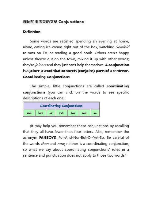
连词的用法英语文章ConjunctionsDefinitionSome words are satisfied spending an evening at home, alone, eating ice-cream right out of the box, watching Seinfeld re-runs on TV, or reading a good book. Others aren't happy unless they're out on the town, mixing it up with other words; they're joiners and they just can't help themselves. A conjunction is a joiner, a word that connects (conjoins) parts of a sentence. Coordinating ConjunctionsThe simple, little conjunctions are called coordinating conjunctions(you can click on the words to see specific descriptions of each one):(It may help you remember these conjunctions by recalling that they all have fewer than four letters. Also, remember the acronym FANBOYS: For-And-Nor-But-Or-Yet-So. Be careful of the words then and now; neither is a coordinating conjunction, so what we say about coordinating conjunctions' roles in a sentence and punctuation does not apply to those two words.)When a coordinating conjunctiontwo independent clauses, it is often (butalways) accompanied by a comma:•Ulysses wants to play for UConn, but he hasWhen the two independentconnected by a coordinating conjunctioncomma:•Ulysses has a great jump shot but hequick on his feet.The comma is always correct when usedseparate two independent clauses connected by a coordinating conjunction. See Punctuation Between Two Independent Clauses for further help.A comma is also correct when and is used to attach the last item of a serial list, although many writers (especially in newspapers) will omit that final comma:•Ulysses spent his summer studying basic math, writing, and reading comprehension.When a coordinating conjunction is used to connect all the elements in a series, a comma is not used:•Presbyterians and Methodists and Baptists are the prevalent Protestant congregations in Oklahoma.A comma is also used with but when expressing a contrast:•This is a useful rule, but difficult to remember.In most of their other roles as joiners (other than joining independent clauses, that is), coordinating conjunctions can join two sentence elements without the help of a comma.•Hemingway and Fitzgerald are among the Americanexpatriates of the between-the-wars era.•Hemingway was renowned for his clear style and his insights into American notions of male identity.•It is hard to say whether Hemingway or Fitzgerald is the more interesting cultural icon of his day.•Although Hemingway is sometimes disparaged for his unpleasant portrayal of women and for his glorification of machismo, we nonetheless find some sympathetic, even heroic, female figures in his novels and short stories.Beginning a Sentence with And or ButA frequently asked question about conjunctions is whetherand or but can be used at the beginning of a sentence.This is what R.W. Burchfield has to say about this use ofand:There is a persistentbelief that it isimproper to begin asentence with And,but this prohibitionhas been cheerfullyignored by standardauthors from Anglo-Saxon times onwards.An initial And is auseful aid to writersas the narrativecontinues.from The New Fowler's Modern English Usageedited by R.W. Burchfield. Clarendon Press: Oxford, England. 1996.Used with the permission of Oxford University Press.The same is true with the conjunction but. A sentencebeginning with and or but will tend to draw attention toitself and its transitional function. Writers shouldexamine such sentences with two questions in mind: (1)would the sentence and paragraph function just as wellAmong the coordinating conjunctions, the most common, of course, are and, but, and or. It might be helpful to explore the uses of these three little words. The examples below by no means exhaust the possible meanings of these conjunctions.ANDa.To suggest that one idea is chronologically sequential to another: "Tashonda sent in her applications and waited by the phone for a response."b.To suggest that one idea is the result of another: "Willie heard the weather report and promptly boarded up his house."c.To suggest that one idea is in contrast to another (frequently replaced by but in this usage): "Juanita is brilliant and Shalimar has a pleasant personality.d.To suggest an element of surprise (sometimes replaced by yet in this usage): "Hartford is a rich city and suffers from many symptoms of urban blight."e.To suggest that one clause is dependent upon another, conditionally (usually the first clause is an imperative): "Use your credit cards frequently and you'll soon find yourself deep in debt."f.T o suggest a kind of "comment" on the first clause: "Charlie became addicted to gambling — and that surprised no one who knew him."BUTa.To suggest a contrast that is unexpected in light of the first clause: "Joey lost a fortune in the stock market, but he still seemsable to live quite comfortably."b.To suggest in an affirmative sense what the first part of the sentence implied in a negative way (sometimes replaced by on the contrary): "The club never invested foolishly, but used the services of a sage investment counselor."c.To connect two ideas with the meaning of "with the exception of" (and then the second word takes over as subject): "Everybody but Goldenbreath is trying out for the team."ORa.To suggest that only one possibility can be realized, excluding one or the other: "You can study hard for this exam or you can fail."b.To suggest the inclusive combination of alternatives: "We can broil chicken on the grill tonight, or we can just eat leftovers.c.To suggest a refinement of the first clause: "Smith College is the premier all-women's college in the country, or so it seems to most Smith College alumnae."d.To suggest a restatement or "correction" of the first part of the sentence: "There are no rattlesnakes in this canyon, or so our guide tells us."e.To suggest a negative condition: "The New Hampshire state motto is the rather grim "Live free or die."f.T o suggest a negative alternative without the use of an imperative (see use of and above): "They must approve his political style or they wouldn't keep electing him mayor."Authority used for this section on the uses of and, but, and or: A University Grammar of English by Randolph Quirk and Sidney Greenbaum. Longman Group: Essex, England. 1993. Used with permission. Examples our own.The Others . . .The conjunction NOR is not extinct, but it is not used nearly as often as the other conjunctions, so it might feel a bit odd when nor does come up in conversation or writing. Its most common use is as the little brother in the correlative pair, neither-nor (see below):•He is neither sane nor brilliant.•That is neither what I said nor what I meant.>It can be used with other negative expressions:•That is not what I meant to say, nor should you interpret my statement as an admission of guilt.It is possible to use nor without a preceding negative element, but it is unusual and, to an extent, rather stuffy:•George's handshake is as good as any written contract, nor has he ever proven untrustworthy.The word YET functions sometimes as an adverb and has several meanings: in addition ("yet another cause of trouble" or "a simple yet noble woman"), even ("yet more expensive"), still ("he is yet a novice"), eventually ("they may yet win"), and so soon as now ("he's not here yet"). It also functions as a coordinating conjunction meaning something like "nevertheless" or "but." The word yet seems to carry an element of distinctiveness that but can seldom register.•John plays basketball well, yet his favorite sport is badminton.•The visitors complained loudly about the heat, yet they continued to play golf every day.In sentences such as the second one, above, the pronoun subject of the second clause ("they," in this case) is often left out. When that happens, the comma preceding the conjunction might also disappear: "The visitors complained loudly yetcontinued to play golf every day."Yet is sometimes combined with other conjunctions, but or and. It would not be unusual to see and yet in sentences like the ones above. This usage is acceptable.The word FOR is most often used as a preposition, of course, but it does serve, on rare occasions, as a coordinating conjunction. Some people regard the conjunction for as rather highfalutin and literary, and it does tend to add a bit of weightiness to the text. Beginning a sentence with the conjunction "for" is probably not a good idea, except when you're singing "For he's a jolly good fellow. "For" has serious sequential implications and in its use the order of thoughts is more important than it is, say, with because or since. Its function is to introduce the reason for the preceding clause:•John thought he had a good chance to get the job, for his father was on the company's board of trustees.•Most of the visitors were happy just sitting around in the shade, for it had been a long, dusty journey on the train.Be careful of the conjunction SO. Sometimes it can connect two independent clauses along with a comma, but sometimes it can't. For instance, in this sentence,•Soto is not the only Olympic athlete in his family, so are his brother, sister, and his Uncle Chet.where the word so means "as well" or "in addition," most careful writers would use a semicolon between the two independent clauses. In the following sentence, where so is acting like a minor-league "therefore," the conjunction and the comma are adequate to the task:•Soto has always been nervous in large gatherings, so it is no surprise that he avoids crowds of his adoring fans.Sometimes, at the beginning of a sentence, so will act as a kind of summing up device or transition, and when it does, it is often set off from the rest of the sentence with a comma:•So, the sheriff peremptorily removed the child from the custody of his parents.The Case of Then and ThanIn some parts of the United States, we are told, then andthan not only look alike, they sound alike. Like a teacherwith twins in her classroom, you need to be able todistinguish between these two words; otherwise, they'llbecome mischievous. They are often used and they shouldbe used for the right purposes.Than is used to make comparisons. In the sentence "Piggywould rather be rescued then stay on the island," we haveemployed the wrong word because a comparison is being madebetween Piggy's two choices; we need than instead. In the sentence, "Other than Pincher Martin, Golding did notwrite another popular novel," the adverbial construction"other than" helps us make an implied comparison; thisusage is perfectly acceptable in the United States butcareful writers in the UK try to avoid it (Burchfield). Generally, the only question about than arises when wehave to decide whether the word is being used as a conjunction or as a preposition. If it's a preposition(and Merriam-Webster's dictionary provides for thisusage), then the word that follows it should be in theobject form.•He's taller and somewhat more handsome than me.•Just because you look like him doesn't mean you canplay better than him.Most careful writers, however, will insist that than beused as a conjunction; it's as if part of the clauseintroduced by than has been left out:•He's taller and somewhat more handsome than I [amhandsome].•You can play better than he [can play].In formal, academic text, you should probably use than asa conjunction and follow it with the subject form of apronoun (where a pronoun is appropriate).Then is a conjunction, but it is not one of the little conjunctions listed at the top of this page. We can usethe FANBOYS conjunctions to connect two independentclauses; usually, they will be accompanied (preceded) bya comma. Too many students think that then works the sameway: "Caesar invaded Gaul, then he turned his attentionto England." You can tell the difference between then anda coordinating conjunction by trying to move the wordaround in the sentence. We can write "he then turned hisattention to England"; "he turned his attention, then, to England"; he turned his attention to England then." Theword can move around within the clause. Try that with a conjunction, and you will quickly see that the conjunctioncannot move around. "Caesar invaded Gaul, and then heturned his attention to England." The word and is stuckexactly there and cannot move like then, which is morelike an adverbial conjunction (or conjunctive adverb —see below) than a coordinating conjunction. Our originalsentence in this paragraph — "Caesar invaded Gaul, thenhe turned his attention to England" — is a comma splice,a faulty sentence construction in which a comma tries tohold together two independent clauses all by itself: thecomma needs a coordinating conjunction to help out, andthe word then simply doesn't work that way.Subordinating ConjunctionsA Subordinating Conjunction(sometimes called a dependent word or subordinator) comes at the beginning of a Subordinate (or Dependent) Clause and establishes the relationship between the dependent clause and the rest of the sentence. It also turns the clause into something that depends on the rest of the sentence for its meaning.•He took to the stage as though he had been preparing for this moment all his life.•Because he loved acting, he refused to give up his dream of being in the movies.•Unless we act now, all is lost.Notice that some of the subordinating conjunctions in the table below — after, before, since — are also prepositions, but as subordinators they are being used to introduce a clause and to subordinate the following clause to the independent element in the sentence.•It looks like as if it's going to snow this afternoon.•Johnson kept looking out the window like as though he had someone waiting for him.In formal, academic text, it's a good idea to reserve the use of like for situations in which similarities are being pointed out:•This community college is like a two-year liberal arts college.However, when you are listing things that have similarities, such as is probably more suitable:•The college has several highly regarded neighbors, like such as the Mark Twain House, St. FrancisHospital, the Connecticut Historical Society, andthe UConn Law School.•The problem is, that production in her department has dropped.•Remember, that we didn't have these problems before she started working here.As a general rule, if the sentence feels just as good without the that,if no ambiguity results from its omission, if the sentence is more efficient or elegant without it, then we can safely omit the that. Theodore Bernstein lists three conditions in which we should maintain the conjunction that:•When a time element intervenes between the verb and the clause: "The boss said yesterday that productionin this department was down fifty percent." (Noticethe position of "yesterday.")•When the verb of the clause is long delayed: "Our annual report revealed that some losses sustainedby this department in the third quarter of last yearwere worse than previously thought." (Notice thedistance between the subject "losses" and its verb,"were.")•When a second that can clear up who said or did what: "The CEO said that Isabel's department wasslacking off and that production droppedprecipitously in the fourth quarter." (Did the CEOsay that production dropped or was the drop a resultof what he said about Isabel's department? Thesecond that makes the sentence clear.)Authority for this section: Dos, Don'ts & Maybes of English Usage by Theodore Bernstein. Gramercy Books: New York. 1999. p. 217. Examples our own.clause.•Because e-mail now plays such a huge role in ourcommunications industry.When the "because clause" is properly subordinated toanother idea (regardless of the position of the clause inthe sentence), there is absolutely nothing wrong with it: •Because e-mail now plays such a huge role in ourcommunications industry, the postal service wouldvery much like to see it taxed in some manner. Correlative ConjunctionsSome conjunctions combine with other words to form what are called correlative conjunctions. They always travel in pairs, joining various sentence elements that should be treated as grammatically equal.•She led the team not only in statistics but also by virtue of her enthusiasm.•Polonius said, "Neither a borrower nor a lender be."•Whether you win this race or lose it doesn't matter as long as you do your best.Correlative conjunctions sometimes create problems in parallel form. Click HERE for help with those problems. Here is a brief list of common correlative conjunctions.Conjunctive AdverbsThe conjunctive adverbs such as however, moreover, nevertheless, consequently, as a result are used to create complex relationships between ideas. Refer to the section on Coherence: Transitions Between Ideas for an extensive list of conjunctive adverbs categorized according to their various uses and for some advice on their application within sentences (including punctuation issues).Guide to Grammar and Writing Principles of CompositionIndexThe Guide to Grammar and Writing is sponsored by the Capital Community College Foundation, a nonprofit 501 c-3 organization that supports scholarships, faculty development, and curriculum innovation. If you feel we have provided something of value and wish to show your appreciation, you can assist the College and its students with a tax-deductible contribution.For more about giving to Capital, write to CCC Foundation, 950 Main Street, Hartford, CT 06103. Phone (860) 906-5102 or email: *********************.edu. Contributions are tax-deductible to the extent allowed by law.。
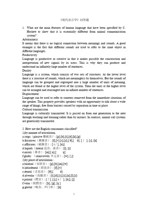
《现代语言学》问答题1.What are the main features of human language that have been specified by C.Hockett to show that it is essentially different from animal communication system?ArbitrarinessIt means that there is no logical connection between meanings and sounds. A good example is the fact that different sounds are used to refer to the same object in different languages.ProductivityLanguage is productive or creative in that it makes possible the construction and interpretation of new signals by its users. This is why they can produce and understand an infinitely large number of sentences.DualityLanguage is a system, which consists of two sets of structures. At the lower level there is a structure of sounds, which are meaningless by themselves. But the sounds of language can be grouped and regrouped into a large number of units of meaning, which are found at the higher level of the system. Then the units at the higher level can be arranged and rearranged into an infinite number of sentences. DisplacementLanguage can be used to refer to contexts removed from the immediate situations of the speaker. This property provides speakers with an opportunity to talk about a wide range of things, free from barriers caused by separation in time or place.Cultural transmissionLanguage is culturally transmitted. It is passed on from one generation to the next through teaching and learning rather than by instinct. In contrast, animal call systems are genetically transmitted.2. How are the English consonants classified?1)by manner of articulation.a.stops(plosive爆破音): [p],[b],[t],[d],[k],[g]b.fricatives(磨擦音): [f],[v],[s],[z],[ θ],[ð], [∫], [ʒ], [h]c.affricates(破擦音): [ t∫], [dʒ]d.liquids(lateral边音,流音): [l], [r]e.nasals(鼻音): [m],[ n],[ŋ]f.glides (semivowels半元音): [w], [ j]2)by place of articulation :a.bilabial(双唇音): [p],[b],[m],[w]biodental(唇齿音): [f],[v]c.dental(舌齿音): [θ],[ ð]d.alveolar(齿龈音): [t],[d],[s],[z],[n],[l],[r]e.palatal(腭音): [∫], [ʒ],[ t∫], [dʒ], [j]f.velar(软腭音): [k], [g], [ŋ ]g.glottal(喉音,声门单): [h]3. What criteria are used to classify the English vowels? 英语的元音是如何分类的?1) According to the position of the tongue, vowels may be distinguished as front vowels such as [i:] [i] [e] [æ] [a], central vowels such as [ɜ:] [ə] [ʌ], and back vowels such as [u:] [ʊ] [ɔ:] [ɔ] [ɑ:]2) According to the openness of the mouth, we classify the vowels into four groups: close vowels such as [i:] [i] [u:] [ʊ], semi-close vowels such as [e] [ɜ:], semi-open vowels such as [ə] [ɔ:], and open vowels such as [æ] [a] [ʌ] [ɔ] and [ɑ:].3) According to the shape of the lips, vowels are divided into rounded vowels and unrounded vowels. In English all the front and central vowels are unrounded vowels, all the back vowels, with exception of [ɑ:], are rounded.4) According to the length of the vowels, the English vowels can also be classified into long vowels and short vowels. The long vowels include [i:] [ɜ:] [ɔ: ] [u:] [ɑ:],while the rest are short vowels.4. What are phonemic contrast, complementary distribution, and minimal pair?If two phonetically similar sounds can occur in the same environments and they distinguish meaning, they are in phonemic contrast. [p], [b]If two phonetically similar sounds are two allophones of the same phoneme and they occur in different environments, they are said to be in complementary distribution. [p], [ph].When two different forms are identical in every way except for one sound segment which occurs in the same place in the strings, the two words are said to form a minimal pair. For example, kill and bill.5. Explain with examples the sequential rule, the assimilation rule, and the deletion rule.Sequential rule refers to the rule that governs the combination of sounds in a particular language.For example, if a word begins with a [l] or a [r] , then the next sound must be a vowel. If three consonants should cluster together at the beginning of a word, the combination should obey the following three rules:the first phoneme must be /s/the second phoneme must be /p/ or /t/ or /k/the third phoneme must be /l/ or /r/ or /w/Assimilation rule assimilates one sound to another by “copying” a feature of a sequential phoneme, thus making the two phones similar.For example, the [i:] sound in words like bean, green, team, and scream. This is because in all these sound combinations the [i:] sound is followed by a nasal [n] or [m].Deletion rule tells us when a sound is to be deleted although it is orthographically represented.For example, in the pronunciation of the word sign or design, there is no [g] soundalthough it is represented in spelling by the letter g. But in their corresponding forms signature, designation, the [g] represented by the letter g is pronounced. The rule: delete a [g] when it occurs before a final nasal consonant.6. What are suprasegmental features? How do the major suprasegmental features of English function in conveying meaning?Suprasegmental features are phonological features above the sound segment level. The major suprasegmental features in English are word stress, sentence stress and intonation.1)The location of stress in English distinguishes meaning, such as `import and im`port. The similar alternation of stress also occurs between a compound noun and a phrase consisting of the same elements. A phonological feature of the English compounds is that the stress of the word always falls on the first element and the second element receives secondary stress, for example: `blackbird is a particular kind of bird, which is not necessarily black, but a black `bird is a bird that is black.2) Sentence stress refers to the relative force which is given to the words in a sentence. The more important words such as nouns, main verbs, adjectives, adverbs, and demonstrative pronouns, are pronounced with greater force and made more prominent. And the other categories of words (articles, personal pronouns, auxiliary verbs, prepositions, and conjunctions) are usually not stressed. But to give special emphasis to a certain notion, a word in sentence that is usually unstressed can be stressed to achieve different effect. Take the sentence “He is driving my car.” For example, to emphasize the fact that the car he is driving is not his, or yours, but mine, the speaker can stress the possessive pronoun my, which under normal circumstances is not stressed.3)English has four basic types of intonation: When spoken in different tones, the same sequence of words may have different meanings. Generally speaking, the falling tone indicates that what is said is a straight-forward, matter-of-fact statement, the rising tone often makes a question of what is said, and the fall-rise tone often indicates that there is an implied message in what is said.7. Discuss the types of morphemes with examples.Free morphemes: They are the independent units of meaning and can be used freely all by themselves, for example, “book-” in the word “bookish”.Bound morphemes: They are those that cannot be used independently but have to be combined with other morphemes, either free or bound, to form a word such as “-ish” in “bookish”.Bound morphemes can be subdivided into roots and affixes. A root is seen as part of a word; it can never stand by itself although it has a clear and definite meaning, such as “gene-” in the word “generate”. Affixes are of two types: inflectional and derivational. Inflectional morphemes manifest various grammatical relations or grammatical categories such as “-s” in the word “books” to indicate plurality of nouns. Derivational affixes are added to an existing form to create a word such as “mis-” in the word “misinform”. Derivational affixes can also be divided into prefixes andsuffixes. Prefixes occur at the beginn ing of a word such as “dis- ” in the word “dislike”, while suffixes occur at the end of a word such as “-less” in the word “friendless”.8. What is the relation between sense and reference?Sense and reference are two terms in the study of meaning. (1) Sense is concerned with the inherent meaning of the linguistic form. It is the collection of all the features of the linguistic form; it is abstract and de-contextualized. It is the aspect of meaning that dictionary compilers are interested in. Reference means what a linguistic form refers to in the real, physical world; it deals with the relationship between the linguistic element and the non-linguistic world of experience. (2) Obviously, linguistic forms having the same sense may have different references in different situations. On the other hand, there are less frequent occasions when linguistic forms with the same reference might differ in sense, e.g. “morning star” and “evening star”.9. What are the major lexical sense relations?1)Synonymya)Dialectal synonyms --- regional dialectse.g. British English: autumn/liftAmerican English: fall/elevatorb)Stylistic synonymse.g. old man, daddy, dad, father, male parentc)Synonyms that differ in their emotive or evaluative meaninge.g. collaborator & accompliced)collocational synonymse.g. accuse…of/ charge…with/ rebuke…fore)semantically different synonymse.g. amaze: confusion and bewildermentastound: difficulty in believing2)Polysemye.g. “table” has many meanings such as 1.a piece of furniture 2. a level area, a plateau and etc.3)HomonymyHomophones: identical in sound e.g. night/ knightHomographs: identical in spelling e.g. bow v./ bow n.4)Hyponymye.g. superordinate: furniturehyponyms: bed, table5)Antonymya)Gradable antonymse.g. old and young are immediately recognized as antomyms, between whichthere exist intermediate forms such as “mature”, “middle-aged”b)complementary antonymse.g. a person can be either alive or dead; there is no third possibilityc)Relational oppositese.g. husband and wife are a paior of relational opposites.10. Illustrate Searle’s classification of speech acts with examples.According to Searle, speech acts fall in five general categories. Specific acts that fall into each type share the same illocutionary point, but differ in their strength.1)Representatives/assertives: stating or describing, saying what the speaker believes to be trueTypical cases: stating, believing, swearinge.g. (I swear)I have never seen the man before.(I state)The earth is a globe.2)Directives: trying to get the hearer to do somethingTypical cases: Inviting, suggesting, requesting, advising, warning, threatening, orderinge.g. Open the window, please.You’d better go to the clinic.3)Commissives: committing the speaker himself to some future course of action Typical cases: Promising, undertaking, vowinge.g. I promise to come.4)Expressives: expressing feelings of attitude towards an existing stateTypical cases: apologizing, thanking, congratulatinge.g. I’m sorry for the mess I have made.It’s really kind of you to have thought of me.5)Declarations: bringing about immediate changes by saying somethingThe successful performance of an act of this type brings about the correspondence between what is said and reality.e.g. I now declare the meeting open.I fire you!11. Illustrate Grice's Cooperative Principle with examples.Grice's Cooperative Principle consists of four maxims: QUANTITY, QUALITY, RELATION, and MANNER.1)A: What are you reading?B: A book.A knowsB is reading a book, and is asking about the content of the book. Simply by saying "a book", B is not offering enough information. The implicature here is: I do not want to talk to you right now. In this case, the maxim of QUANTITY is violated.2)He is made of iron.Our common sense tells us no human being is made of iron. Obviously this is a false statement and has violated the maxim of QUALITY. The implicature here is: he is as strong as iron.3)A: Mrs. Smith was such a bore at the party last night.B: It's really chilly here. I want to go out to warm up.When A is talking about Mrs. Smith, B turns to talk about something totally irrelevant.Therefore the maxim of RELATION is violated. The implicature here is: It is impolite to say that.4)a. Miss Smith sang "Home sweet home".b. Miss Smith produced a series of sounds that corresponded closely with the song of "Home sweet home".The two sentences actually are basically talking about the same thing. But sentence b is stated in such a way that makes it more obscure for the audience and therefore violates the maxim of MANNER. The implicature here is: Miss Smith does not sing well and I do not like her singing.12. With examples, give some plausible explanations for linguistic change.The rapid development of science and technologye.g. fax, laser printer, hi-tech, CD-ROM, lapto p computer and etc.Social and political changes and political needse.g. mini-summit, jungle war, Euro and etc.more and more women have taken up activities formerly reserved for mene.g. chairman---chairpersonfireman---fire fighterpoliceman---police officerThe way children acquire a languagee.g. “It’s I.”---“It’s me”.Economy of memory(results in grammar simplification)e.g. By analogy to foe/foes, dog/dogs, speaker started saying cows as the plural of cow instead of kine.Theory of least efforte.g. Cheap is always used in the place of cheaplySimplification of grammar occurs, so does elaboration and complication.13. Is standard language better than non-standard language? Explain your answer.The standard language is a superposed, socially prestigious dialect of language. It is the language employed by the government and the judiciary system, used by the mass media, and taught in educational institutions, including school settings where the language is taught as a foreign or second language. Nonstandard, or vernacular, languages are language varieties other than the standard language. Standard language is not superior to nonstandard language at all. The designation of the standard language variety is motivated by historical and socio-political reasons and has nothing to do with any supposed linguistic superiority intrinsic to the grammatical components of that particular language variety. In view of language as an effective means of communication, no single dialect of a language, be it standard or nonstandard, is any more correct, any more logical, or any purer than any other dialect of the language. All dialects of a language are equally effective in expressing ideas.14. What is the relationship between pidgin and creole?A pidgin is a variety of language that is generally used by native speakers of otherlanguages as a medium of communication. A pidgin is used for some practical purposes, such as trading, by groups of people who do not know each other' s languages. It is not a native language of a particular region, but only a marginal language used by people whose cultures are sharply separated and whose business contact is very specialized .As a simplified language, a pidgin involves reductions in sounds, vocabulary and syntax. Although pidgins are simplified languages, they are rule-governed.A Creole language is originally a pidgin that has become established as a native language in some speech community. When a pidgin comes to be adopted by a population as its primary language, and children learn it as their first language, then the pidgin language is called a creole. A creole involves expansion in sounds, vocabulary and syntax. Creoles are fully developed languages.。
语言学辽宁慕课习题整理chapter1-7Chapter 1 Invitations to linguistics1introduction to linguistics选择题1、Which of the following statements is NOT true?A Language consists of the systems of sounds and grammar.B Language is instrumental.C Language is social and conventional.D Language is a system of symbols.2、The scope of linguistic study may be generally divided into ______________.A interlinguistic study and extralinguistic studyB sociolinguistics and psycholinguisticsC descriptive linguistics and prescriptive linguisticsD phonetics and phonology3、Saussure made the distinction between _______________.A Langue and paroleB theoretical linguistics and applied linguisticsC comparative linguistics and historical linguisticsD competence and performance4、Chomsky made the distinction between _______________.A diachronic linguistics and synchronic linguisticsB Langue and paroleC competence and performanceD comparative linguistics and historical linguistics5、As modern linguistics aims to describe and analyze the language people actually use, and not to lay down rules for “correct” linguistic behavior, it is said to be ___________.A prescriptiveB descriptiveC sociolinguisticD psycholinguistic判断题6、Language consists of the systems of sounds and grammar.7、The actual production and comprehension of the speech by speakers of a language is called performance.8、English is an intonation language.9、The fact that children can speak before they can read or write shows that language is arbitrary.10、According to Chomsky, a language user’s underlying knowledge about the system of rules is called his linguistic competence.答案:AAACB X√√X√2design features of language选择题1、Which of the following is NOT a frequently discussed design feature of language?A DualityB ConventionC DisplacementD Arbitrariness.2、“I can refer to Confucius even though he died 2000 years ago.” This shows that language has the design feature of __________.A dualityB creativityC arbitrarinessD displacement3、The design feature of __________ refers to the property ofhaving two levels of structures, such that units of the primary level are composed of elements of the secondary level.A arbitrarinessB creativityC displacementD duality4、One of the properties of language is that a language user can understand and produce sentences he/she has never heard before. This property of language is called ________.A productivityB dualityC displacementD arbitrariness5、In broad terms, linguists agree to define language as a system of ____vocal symbols used for human communication.A arbitraryB conventionalC motivatedD dual答案:BDDAA3origins of language选择题1、There are some well-known theories about the origin of language, the natural response theory, also called .A the sing-song theoryB the pooh-pooh theoryC the Ding-Dong theoryD the yo-he-ho theory2、Ding-Dong theory is put forward by German scholar .A M. MULLerB HallidayC SaussureD Malinowski3、holds that language develops from primitive ritual songs of praise.A the yo-he-ho theoryB The sing-song theoryC the pooh-pooh theoryD the Ding-Dong theory4、holds that language originated from people’s imitations of animal cries and other sounds heard in nature.A The bow-wow theoryB the pooh-pooh theoryC the yo-he-ho theoryD the Ding-Dong theory判断题5、The bow-wow theory is a theory on the origin of language.6、Now linguists have known the specific origin of language.7、The yo-he-ho theory explains that language originated from the cries uttered during strain of work.答案:CABA √X√4functions of language选择题1、When people use language to express attitudes, feelings and emotions, people are using the ____________function of language.A creativeB phaticC emotiveD metalingual2、The social functions of language do NOT include_______________.A interrogative functionB phatic functionC metacognitive functionD informative function3、Which of the following is NOT a metafunction of language proposed by Halliday?A IdeationalB ConventionalC InterpersonalD Textual4、The social functions of language do NOT include_______________.A interrogative functionB informative functionC metacognitive functionD phatic function5、The ______ function refers to the fact that language can be used for establishing a favorable atmosphere or maintaining social contact rather than for exchanging information or ideas.A phaticB evocativeC directiveD performative判断题6、“Language operates by rules” is a fu ndamental view about language.7、When people use language to indulge in itself for its ownsake, people are using the creative function of language.8、According to Halliday’s theory of metafunctions of language, interpersonal function enacts social relationship.9、According to Halliday, a theory of metafunctions of language, that is , language has ideational, interpersonal and textual function.10、When people use language to indulge in itself for its own sake, people are using the poetic function of language.答案:CCBCA √X√√√Chapter 1 主观题1、名词解释:Diachronic linguisticsDiachronic linguistics is the study of a language through the course of its history.2、名词解释:Synchronic linguisticsA synchronic description takes a fixed instant (usually, but not necessarily, the present) as its point of observation.3、名词解释:PsycholinguisticsPsycholinguistics is the study of psychological aspects of language; it usually studies the psychological states and mental activity associated with the use of language. Most problems in psycholinguistics are more concrete, involving the study of language acquisition especially in children and linguistic performance such as producing and comprehending utterances or sentences among adults.4、名词解释:DualityBy Duality is meant the property of having two levels of structures, such that units of the primary level are composed of elements of the secondary level and each of the two levels has its own principles of organization. The property of duality only exists in such a system, namely, with both elements and units.Besides, the language is hierarchical.5、名词解释:DisplacementDisplacement means that human languages enable their users to symbolize objects, events and concepts which are not present (in time and space) at the moment of communication. Displacement benefits human beings by giving them the power to handle generalizations and abstractions. In a word, the intellectual benefits of displacement to us is that it makes it possible for us to talk and think in abstract terms.6、Do you think that onomatopoeia indicates a non-arbitrary relationship between form and meaning? Why or why not?No matter whether you say “Yes” or “No”, you cannot deny that onomatopoeia needsarbitrariness. Before we feel a word is onomatopoeic we should first know which sound the word imitates. In order to imitate the noise of flying mosquitoes, there are many choices like “murmurous” and “murderous”. They both bear more or less resemblance to the genuine natural sound, but “murmurous” is fortunately chosen to mean the noise while “murderous” is chose n to mean something quite different. They are arbitrary as signifiers.(参考答案)No, I don't think so. There exists the arbitrary relationship between the sound of a morpheme and its meaning. Also, in English, totally different words are used to describe the sound. In fact, arbitrariness and onomatopoeic effect may work at the same time. For example, Widdowson cites a line from Keats' Ode to a Nightingale to illustrate. The murmurous haunt of flies on summer eves. To test this, just think of using the similar sounding word murderous to substitute murmurous, and no connectionwhatsover will be established between the sounds and the little noises of the flying flies. "It's only when you know the meaning that you infer that the form is appropriate." (我的答案)7、Illustrate the origins of language you have known.The sing-song theory: it holds that language develops from primitive ritual songs of praise.The Ding-Dong theory: the natural response theory postulates that language began with vocal expressions being assigned to objects found in the environment.The pooh-pooh theory: the theory traces language back to interjections which expresses the speakers’ emotions.The yo-he-ho theory: it explains that language originated form the cries uttered during strain of work.The bow-wow theory: it holds that language originated from people’s imitations of animal cries and other sounds heard in nature.Ta-Ta theory: it believes that body movement preceded language. language began as an unconscious vocal imitation of these movements.8、Language is generally defined as a system of arbitrary vocal symbols used for human communication. Explain it in detail.Language is a means of verbal communication. It is instrumental in that communicating by speaking or writing is a purposeful act. It is social and conventional in that language is a social semiotic and communication can only take place effectively if all the users share a broad understanding of human interaction including such associated factors as nonverbal cues, motivation, and socio-cultural roles.Chapter 2 Phonetics5phonetics选择题1、Pair ___________ doesn’t form a minimal pair.A cat and actB tip and dipC gap and capD pat and pad2、The study of the production of speech sounds is closely connected with ____________.A articulatory phoneticsB auditory phoneticsC acoustic phoneticsD arbitrary phonetics3、The study of the physical properties of speech sounds is closely connected with ____________.A acoustic phoneticsB articulatory phoneticsC auditory phoneticsD arbitrary phonetics4、The study of the perception of speech sounds is closely connected with .A acoustic phoneticsB articulatory phoneticsC auditory phoneticsD arbitrary phonetics5、Pair ________is not in complementary distribution.A spot and potB stop and topC light and gladD school and cool判断题1、A single phoneme always represents a single morpheme.2、When the vocal folds are apart, the air can pass through easily and the sound produced is said to be voiced.3、Cave and shave forms a minimal pair.4、Phonetics studies how speech sounds are produced, transmitted, and perceived.5、The tongue is divided into five parts: the tip, the blade, the front, the back and the root.主观题1、Please describe what is phoneme.The speech sound segments that can distinguish or contrast words in sound and meaning are phonemes. (A phoneme is the minimal or smallest distinctive linguistic unit in a language.)2、Please describe what is complementary distribution.The different allophones of the same phoneme never occur in the same phonetic context. When two or more allophones of one phoneme never occur in the same linguistic environment they are said to be in complementary distribution.答案:AAACC ××√√√6English Consonan t选择题1、The classification and description of English consonants are based on ___________________.A narrow and broad transcriptionB the shape of vocal tractC the place and manner of articulationD the position of the tongue2、According to the manner of articulation, [m] is a ___________.A nasalB plosiveC bilabialD lateral3、In terms of the place of articulation, the following sounds [t], [n], [z] share the feature of ____________.A alveolarB velarC palatalD bilabial4、Which of the following sounds is a bilabial?A [ t ]B [ b ]C [ g ]D [ d ]5、Which of the following sounds is an alveolar?A [ d ]B [ m ]C [ g ]D [ b ]判断题1、The difference between vowels and consonants lies in the obstruction of the airstream.2、According to the manner of articulation, [s] is a fricative.3、English consonants can be classified in terms of place of articulation and the part of the tongue that is raised the highest.4、According to the manner of articulation, some of the types into which the consonants can be classified are stops, fricatives, bilabial and alveolar.5、/d/ is a voiced alveolar stop.主观题Please describe what are consonants.Consonants are sounds produced by constricting or obstructing the vocal tract at some place to divert, impede or completely shut off the flow of the air in the oral cavity.答案:CAABA √√××√7English Vowels1、The classification and description of English vowels are based on ___________________.A the position of the tongueB the shape of the lipsC the shape of vocal tractD all of the above2、The difference between vowels and consonants lies in ___________________.A the intonation of the soundsB the obstruction of the airstreamC the place and manner of articulationD the aspiration of the sounds3、A ____ vowel is one that is produced with the front part of the tongue maintaining the highest position.A centralB frontC middleD back3、can be differentiated by a number of factors: the position of tongue in the mouth, the openness of the mouth, the shape of the lips, and the length of the vowels.A Consonant soundsB Voicing soundsC Vowel soundsD devoicing sounds主观题1、Please describe what are vowels.V owels are sounds produced without obstruction, so no turbulence or a total stopping of the a ir can be perceived.2、What are the criteria that a linguist uses in classifying vowels?1. V owels may be distinguished as front, central and back in terms of the position of the tongue in the mouth.2. According to how wide our mouth is opened, we classify the vowels into four groups: close vowels, semiclose vowels, semi-open vowels, and open vowels.3. According to the shape of the lips, vowels are divided into rounded vowels and unrounded vowels.4. The English vowels can also be classified into long vowels and short vowels according to the length of the sound.答案:DBBCChapter 3 Phonology8phonology选择题1、Of all the speech organs, the _______ is/are the most flexible.A lipsB tongueC mouthD vocal cords2、A(n) ___________ is a unit that is of distinctive value. It is an abstract unit, a collection of distinctive phonetic features.A soundB phoneC phonemeD allophone3、The different phones which can represent a phoneme in different phonetic environments are called the ____ of that phoneme.A phonesB soundsC allophonesD phonemes4、Since /p/ and /b/ are phonetically similar, occur in the same environments and they can distinguish meaning, they are said to be ___________.A in phonemic contrastB the allophonesC in complementary distributionD minimal pair5、The assimilation rule assimilates one sound to another by “copying”a feature of a sequential phoneme, thus making the two phones ____________.A sameB identicalC exactly alikeD similar判断题1、Phonetics is different from phonology in that the latter studies the combinations of the sounds to convey meaning in communication.2、Phonology is concerned with how the sounds can be classified into different categories.3、The rules governing the phonological patterning arelanguage specific.4、Distinctive features of sound segments can be found running over a sequence of two or more phonemic segments.5、When two different forms are identical in every way except for one sound segment which occurs in the same place in the strings, the two words are said to form a phonemic contrast.主观题What are the major differences between phonology and phonetics?1.They differ in their approach and focus.2.Phonetics is of a general nature; it is interested in all the speech sounds used in all human languages: how they are produced, how they differ from each other, what phonetic features they p ossess, how they can be classified.3.Phonology, on the other hand, is interested in the system of sounds of a particular languag e; it aims to discover how speech sounds in a language form patterns and how these sounds are use d to convey meaning in linguistic communication.答案:BCCA D √×√√×9coarticulation选择题1、When such simultaneous or overlapping articulation are involved, we call the process .A coarticulationB aspirationC nasalizationD epenthesis2、In producing a nasal the soft palate is lowered to allow airflow through the .A nasal tractB vocal foldsC vocal cordsD larynx3、The fact that the vowel in lamb has some quality of the following nasal is a phenomenon we call .A devoicingB velarizationC nasalizationD aspiration4、In coarticulation, if the sound becomes more like the following sound, as in lamb, it is known as .A perseverative coarticulationB aspirationC nasalizationD anticipatory coarticulation5、When we use a simple set of symbols in our transcription, it is called a .A aspirationB narrow transcriptionC nasalizationD broad transcription判断题1、In English, the distinction between aspirated [p?] and unaspirated [p] is not phonemic.2、In the word peak, /p/ is unaspirated, phonetically transcribed as [p]3、Aspiration is a distinctive feature in English.4、In phonetic terms, phonemic transcriptions represent the “narrow” transcription.5、Speech is a continuous process, so the vocal organs donot move from one sound segment to thenext in a series of separate steps.主观题名词解释:CoarticulationCoarticulation:Simultaneous or overlapping articulations, as when the nasal quality of a nasal sound affects the preceding or following sound so that the latter becomes nasalized. If the affected sound becomes more like the following sound, it is known as anticipatory coarticulation; if the sound shows the influence of the preceding sound, it is perseverative coarticulation.答案:AACDD √×××√10suprasegmentals选择题1、Which of the following is NOT a Suprasegmental feature?A toneB intonationC syllableD stress2、In a syllable, a vowel often serves as ____________.A onsetB sequenceC peak or nucleusD coda3、The word “digitalization” consists of _______ syllables, and _________ morphemes.A six/ threeB five/ threeC six/ fourD five /five4、The word “digitalization” consists of _______ syllables, and _________ morphemes.A six/ threeB six/ fourC five /fiveD five/ three5、Distinctive features can be found running over a sequence of two or more phonemic segments. The phonemic features that occur above the level of the segments are called _______.A immediate constituentsB phonetic componentsC suprasegmental featuresD semantic features主观题1、名词解释:suprasegmental featuresThe features that occur above the level of the segments and can distinguish meaning are called suprasegmental features, which include syllable structure, stress, tone and intonation.2、名词解释: intonationWhen pitch, stress and sound length are tied to the sentence rather than the word in isolation,they are collectively known as intonation.3、Illustrate with examples how suprasegmental features can affect meaning.1. The location of stress in English distinguishes meaning, such as `import and im`port. The similar alternation of stress also occurs between a compound noun and a phrase consisting of the same elements. A phonological feature of the English compounds, is that the stress of the word always falls on the firstelement and the second element receives secondary stress, for example: `blackbird is a particular kind of bird, which is not necessarily black, but a black `bird is a bird that is black.2. The more important words such as nouns, verbs adjectives, adverbs, etc. are pronounced with greater force and made more prominent. But to give special emphasis to a certain notion, a word in sentence that is usually unstressed can be stressed to achieve different effect. Take the sentence “He is driving my car.” for example. To emphasize the fact that the car he is driving is not his, or yours, but mine, the speaker can stress the possessive pronoun my, which under normal circumstances is not stressed.3. English has four basic types of intonation, known as the four tones: When spoken in different tones, the same sequence of words may have different meanings. Generally speaking, the falling tone indicates that what is said is a straight-forward, matter-of-fact statement, the rising tone often makes a question of what is said, and the fall-rise tone often indicates that there is an implied message in what is said.答案:CCCBCChapter 4 Morphology11morphology选择题1.Derivational affixes are bound morphemes added to existing form to construct new words. English derivational affixes are divided into ________and _______.A prefixes, infixesB suffixes and infixesC prefixes, suffixesD morphemes, allomorphs2.In the word “unavailability”, ______________ is the root.A unB availableC availD ability3.In today’s grammar we normally say that English does not have a “future tense”. This is because in English ________________.A the future can be expressed in many waysB the future is not expressed by morphological changeC the future is expressed by modal verbsD the future belongs to the category of “aspect”4.The morpheme “vision” in the word “television” is a(n)____________.A inflectional morphemeB bound formC free morphemeD bound morpheme5.Which of the following words is made up of bound morphemes only?A televisioB happinessC ecologyD teacher6.Morpheme is the minimal unit of meanin7.–ing is an “inflectional suffix”8.Stems in English can be classified into derivational morphemes and inflectional morphemes.9.The bound morpheme in “apples” is inflectional morpheme.10.Although is an open-class word.主观题11..名词解释:RootRoot: Root refers to the base form of a word that cannot be further analyzed without loss of identity. That is to say, it is that part of the word that is left when all the affixes are removed. And roots can be further classified into free root morpheme and bound root morpheme.12.名词解释:AllomorphAllomorph: A morpheme, like a phoneme, is a linguistic abstraction, which must be realized as certain phonetic forms or variants in different phonetic environments. Each of the phonetic for ms or variants is a morph. A single morpheme may be phonetically realized as two or more morph s. The different morphs that represent or which are derived from one morpheme is called the allom orphs of that morpheme答案:CCBCC √√×√×12word formation选择题1._________can best describe the following group of words: table--tables, influenza--flu.A Inflection and derivationB Derivation and blendingC Inflection and abbreviationD Compound and derivation2.Which of the following ways of word-formation does not change the grammatical class of the stem?A inflectionB compoundC derivationD coinage3._________can best describe the word formation rules of thefollowing group of words: to burgle (from burglar), Eurodollar (from European + dollar).A Back-formation and blendingB Inflection and derivationC Derivation and blendingD Compound and derivation4._________can best describe the following group of words: table—tables, day + break—daybreak.A Inflection and derivationB Derivation and blending.C Compound and derivation.D Inflection and compound5.__________can be best describe the following group of words: advertisement—ad, bicycle—bike.A abbreviationB compoundC derivationD coinage6.“Invention” is a form of compounding, in which two words are blended by joining the initial par t of the first word and the final part of the second word, or by joining the initial parts of the two w ords.7.Blending is a relatively complex form of compounding.8.Derivation does not change the grammatical class of the stem.9.Derivation can be further divided into two sub-types: the derivational type and the compositional type.10.Inflection shows a relationship between roots and affixes.主观题11.What is the distinction between inflectional affixes andderivational affixes?1.When an affix, usually a suffix in English, indicates the tense of a verb, the plurality of a counta ble noun, or the comparative/superlative degree of an adjective, it is termed as inflectional morphe me. For example, '-ed' in 'worked', '-ing' in 'studying', '-s' in 'books' or 'er' in 'shorter' and 'est' in 'lo ngest' are all inflectional morphemes. Usually, the inflectional morpheme will not change the part of speech of a word to which it is attached.2.But a derivational morpheme usually changes the part of speech of a word to which it is attached . When we attach '-al' to the word 'nation' to form 'national', the part of speech of the word 'nation', i.e. a noun, has been changed into an adjective. As we can see, the concept of derivational morphe me is related to a kind of word formation called derivation.答案:CAADA ×√×√×Chapter 5 Syntax13concept of grammar选择题1.A sentence is considered ____ when it does not conform to the grammatical knowledge in the mi nd of native speakers.A wrongB ungrammaticalC rightD grammatical2. A __________ in the embedded clause refers to the introductory word that introduces the embedded clause.A particleB prepositionC subordinatorD coordinator3. Phrase structure rules have ____ properties.A recursiveB grammaticalC socialD functional4. Phrase structure rules allow us to better understand _____________.A All of the above.B how words and phrases form sentences.C what constitutes the grammaticality of strings of wordsD how people produce and recognize possible sentences5. The syntactic rules of any language are ____ in number.A smallB largeC finiteD infinite判断题6.Descriptive grammar refers to grammarian’s attempt to legislate what speakers’ grammatical rules should be, rather than what they are.7.Grammatical sentences are formed following a set of syntactic rules.8.Universally found in the grammars of all human languages, syntactic rules that comprise the system of internalized linguistic knowledge of a language speaker are known as linguistic competence9.The syntactic rules of any language are finite in number, but there is no limit to the number of sentences native speakers of that language are able to produce and comprehend.10.In a complex sentence, the two clauses hold unequal status, one subordinating the other.答案:DBDDD XX√√√主观题1. What are the basic components of a sentence?Normally, a sentence consists of at least a subject and its predicate which contains a finite verb or a verb phrase.2. What are the major types of sentences? Illustrate them with examples.①Traditionally, there are three major types of sentences. They are simple sentence, coordinate (compound) sentence, and complex sentence. A simple sentence consists of a single clause which contains a subject and a predicate and stands alone as its own sentence.For example: John reads extensively.②A coordinate sentence conta ins two clauses joined by a linking word that is calledcoordinat ing conjunction, such as “and”, “but”, “or”.For example: John is reading a linguistic book, and Mary is preparing for her history exam.A complex sentence contains two, or more, clauses, one of which is incorporated into the other. The two clauses in a complex sentence do not have equal status, one is subordinate to the other.For example: Before John gave her a lecture, Mary showed no interest in linguistics.14Cultural Approach选择题1. A __________ in the embedded clause refers to the introductory word that introduces the embedded clause.。
语言学测试试题答案Concise Linguistics (1)Ⅰ.Directions: Read each of the following statements carefully. Decide which one of the four choices best completes the statement and put the letter A, B, C or D in the brackets. (2%×10=20%)1. The fact that different languages have different words for the same object is a good proof that human language is ______.A. arbitraryB. non-arbitraryC. logicalD. non-productive2. The level of syntactic representation that exists before movement takes place is commonly termed the ______.A. phrase structureB. surface structureC. syntactic structureD. deep structure3. The phenomenon that words having different meanings have the same form is called ______.A. polysemyB. hyponymyC. antonymyD. homonymy4. The utterance …We?re already working 25 hours a day, eight days a week.? obviously violates the maxim of ______.A. qualityB. quantityC. relationD. manner5. The famous quotation from Shakespeare's play “Romeo and Juliet” …A rose by any other name would smell as sweet? well illustrates _______. A. the conventional nature of languageB. the creative nature of languageC. the universality of languageD. the big difference between human language and animalcommunication6. Of the following sound combinations, only _______ is permissible according to the sequential rules in English.A. kiblB. bkilC. ilkbD. ilbk7.The sentence that has a NP and a VP can be shown in a _______ for mula "S→NP VP".A. hierarchicalB. linearC. tree diagramD. vertical8. Predication analysis is a way to analyze _______ meaning.A. phonemeB. wordC. phraseD. sentence9. According to Searle, those illocutionary acts whose point is to commit the speaker to some future course of action are called _______.A. commisivesB. directivesC. expressivesD. declaratives10. The term _______ linguistics may be defined as a way of referring to the approach which studies language change over various periods of time and at various historical stages.A. synchronicB. diachronicC. comparativeD. historical comparative11.Chomsky uses the term _______to refer to the actual realization of alanguage user?s knowledge of the rules of his language in linguistic communication.A. langueB. competenceC. paroleD. performance12. Transformational Generative Grammar was introduced by_______in 1957.A. L. BloomfieldB. F. SaussureC. N. ChomskyD.M. A. K. Halliday13. Synonyms are cla ssified into several kinds. The kind to which …girl? and …lass? belong is called ( ) synonyms.A. stylisticB. dialectalC. emotiveD. collocational14. The illocutionary point of _______ is to express thepsychological state specified in the utterance.A. representativesB. commissivesC. expressivesD. declaratives15. The pair of words “lend” and “borrow” are ___.()A. gradable oppositesB. relational oppositesC. co-hyponymsD. synonyms16. A word with several meanings is called __word.A. a polysemousB. a synonymousC. an abnormalD. a multiple17. The function of the s entence “A nice day, isn't it?” is __.A. informativeB. phaticC. directiveD. performative18. The se mantic components of the word “gentleman” can be expressed as __.A. +animate, +male, +human, -adultB. +animate, +male, +human, +adultC. +animate, -male, +human, -adultD. +animate, -male, +human, +adult19. The kind of antonymy between "married "and "single" is one of__________.(A) converseness(B) relational opposites(C) complementarity (D) gradable opposites20. …This orphan has a father? is a case of ________(A) inconsistency (B) presupposition(C)semantic anomaly (D) tautology21. According to Austin , a speaker, while making an utterance, is in most cases performing _______ acts simultaneously.(A) two(B) three(C)four(D)five22. …Your money or your life?" is an example of _________(A)declarations (B) expressives(C)commissives (D) directives.23.______ are also called rewrite rules.(A) phonological rules(B) morphological rules(C) phrase structure rules(D) transformational rules24.The major components of a transformational grammar are __________(A) syntactic, phonological, and semantic(B)base, deep structure, and surface structure(C)deletion, copying ,addition, and reordering(D)generation and transformation25. …Rotten, addle, rancid, sour? can be best described as _________(A) dialectal synonyms(B) collocationally-restricted synonyms(C) words differing in …styles? or …registers?(D) words differing in emotive or evaluative meaningⅡ. Directions: Fill in the blank in each of the followin g statements with one word, the first letter of which is already given as a clue. Note that you are to fill in ONE word only, and you are not allowed to change the letter given.(1%×10=10%)1. As the first step of their scientific investigation of language,linguists have to observe and collect linguistic facts before they can do anything else.2. Phonological rules that govern the combination of sounds in a particular language are called sequential rules.3. An independent unit of meaning that can be used freely by itself is called a free morpheme.4. The study of the linguistic meaning of words, phrases, and sentences is called semantics.5. In making conversation, the general principle that all participants are expected to observe is called the Cooperative principle proposed by J. Grice.6. If a linguistic study describes and analyzes the language people actually use, it is said to be descriptive.7. Morpheme is the smallest meaningful unit of language.8. Referent is what a linguistic form refers to in the real world; it is a matter of the relationship between form and the reality.9. Although the development of a communicative system is not unique to human beings, the natural acquisition of language as a system of highly abstract rules and regulations for creative communication is what distinguishes humans from all other animal species.10. Language exists in time and changes through time. The description ofa language at some point of time is called a synchronic study of language.11. An essential difference between consonants and vowels is whether the air coming up from the lungs meets with any obstruction when a sound is produced.12. The morphemes that cannot be used by themselves, but must be combined with other morphemes to form words arecalled bound morpheme.13. XP may contain more than just X. For example, the NP "the boy who likes his puppy" consists of Det, N and S, with Det being the specifier, N the head and S the complement.14. Hyponymy is the relationship which obtains between specific and general lexical items. The word that is more general in meaning is called superordinate.15. V owels can be nasalized. The vowel nasalization rule is an assimilation rule, which, for the most part, is caused by articulatory or physiological process in which successive sounds are made identical, or more similar, to one another.16.Clear [1]and dark[1]are allophones of the same one phoneme /1/.They never take the same position in sound combinations, thus they are said to be in complementary distribution.17. A root is often seen as part of a word, but it can never stand by itself although it bears clear, definite meaning.18. A complex sentence contains two or more clauses, one of which is incorporated in the other.19. While the meaning of a sentence is abstract and decontextualized, that of an utterance is concrete and context-dependent.Ⅲ. Directions: Judge whether each of the following statements is true or false. Put a T for true or F for false in the brackets in front of each statement. If you think a statement is false, you must explain why youthink so and give the correct version. (2%×10=20%)(T ) 1.Radar is an example of acronym.(T ) 2.What is a permissible sequence in one language may not be so in another language.( F) 3.English has only three bilabials,which are [p][b][m]. ([W]) (T) 4.Phonetically similar sounds might be related in two possible ways: phonemic contrast and complementary distribution.(F ) 5.In the history of any language the writing system always came into being before the spoken form. (The opposite is right.) ( T) 6.Bloomfield's theory of syntax has two central ideas: one is the notion of discovering procedures and the other is that of constituent structure.( F ) 7.A compound is the combination of only two words. (It can combine more than two words, e.g. stay-at-home ) (T ) 8.Transformational rules are also called rewrite rules.( T) 9. The writing system of a language is always a later invention used to record speech; thus there are still many languages in today?s world that can only be spoken, but not written.(F ) 10.The task of the semantic component is to convert deep structures into surface structures. (transformational component)(T ) 11.Sense relations are in fact a part of the semantic structures of English.( F) 12. In such sound combinations as /bi:p/, /geip/ and /su:p/, the voiceless stop /p/, occurring in the final position, is unaspirated, i.e. pronounced with the strong puff of air withheld to some extent. (aspirated)(F )13. Linguists suggest that language is very variable phenomenon, and that this variability is not governed by any rules. That is one of the reasons why we say language is arbitrary. (The fact that different languages have different words for the same object is a good proof that human language is arbitrary.)(F ) 14.Chomsky thinks that human beings are innately endowed with the capacity to form some concepts rather than others. (…form universal concepts.)(F) 15. The part of speech of the compound is always determined by the part of speech of the second element, without exception. (…not necessarily…. e.g. …Eight-year-old? is an adjective.)(T ) 16. The relationship between the embedded clause and its matrix clause is one of a part to the whole.(T ) 17. The contextualist view of meaning holds that meaning should be studied in terms of the situational context and linguistic context.(T ) 18. Searle?s classification of illocutionary acts is based on the classification of performative verbs.(T )19. A general difference between phonetics and phonology is thatphonetics is focused on the production of speech sounds while phonology is more concerned with how speech sounds distinguish meaning.(F ) 20. Only words of the same parts of speech can be combined to form compounds. (Not necessarily. e.g. open-minded, stay-at-home, etc.)(T ) 21. Sentences are not formed by randomly combining lexical items, but by following a set of syntactic rules that arrange linguistic elements in a particular order.( F) 22. According to Searle's classification of illocutionary acts, inviting, ordering, advising, promising and apologizing all fall into the category of directives. (Promising falls into the category of commissives.)Ⅳ.Directions: Explain the following terms, using one or twoexamples for illustration. (3%×10=30%)1. cultural transmission (as a defining feature of human language)One of the major defining features of human language. Humans are born with the ability to acquire a language, but different from animals, the actual use of human language is not genetically transmitted, rather it is culturally transmitted, i.e. it has to be taught and learnt. (P11)2. phonic medium of languageThe limited range of sounds that are used in human language communication, i.e.the speech sounds. (P13)3. inflectional morphemesInflectional morphemes are morphemes that are used to indicate thegrammatical relations and categories, such as number, tense, degree and case. E.g.-ed,-(e)s,-est in English. workers, children; walking, walked; biggest ; John?s. (P37)4. suprasegmental featuresSuprasegmental features refers to the phonemic features that occur above the level of the segments (phoneme), they are phonological properties of such linguistic units as syllable, word and sentence. The main suprasegmental features include stress, intonation, and tone. (P28)5. locutionary actLocutionary act refers to the act of uttering words, phrases, and clauses.It is the act of conveying literal meaning by means of syntax, lexicon and phonology. For example, by saying "You have left the door wide open",the locutionary act performed by the speaker is that he has uttered all the words and expressed what the words literally mean.6. bound morphemesThe morphemes that cannot be used by themselves, but must be combined with other morphemes to form words are called bound morpheme. For example, -s in dogs, -al in national, and dis- n disclose, cannot occur alone. (P35)7.duality of structureLinguists refer duality (of structure) to the fact that in all languages so far investigated, one finds two levels of structure or patterning. At the first,higher level, language is analyzed in terms of combinations of meaningful units (such as morphemes, words etc.); at the second, lower level, it is seen as a sequence of segments which lack any meaning in themselves, but which combine to form units of meaning. According to Hu Zhanglin et al. (p.6), language is a system of two sets of structures, one of sounds and the other of meaning. This is important for the workings of language. A small number of semantic units (words), and these units of meaning can be arranged and rearranged into an infinite number of sentences (note that we have dictionaries of words, but no dictionary of sentences!). Duality makes it possible for a person to talk about anything within his knowledge. No animal communication system enjoys this duality, or even approaches this honor. (P11)8. hyponymyHyponymy is the relationship which obtains between specific and general lexical items.The word that is more general in meaning is called superordinate.9. surface structureThere are two levels of syntactic structure, deep structure and surface structure. Surface structure correspond to the finalsyntactic form of the sentence which results from appropriate transformations. (P57)10. assimilation ruleThe …assimilation rule? assimilates one segment to another by …copying? afeature of a sequential phoneme, thus making the two phones more similar.(This rule accounts for the raring pronunciation of the nasal[n] that occurs within a word. The rule is that within a word the nasal consonant[n] assumes the same place of articulation as the following consonant. The negative prefix “in-“ serves as a good example. It may be pronounced as [in], or [im] when occurring in different phonetic contexts: e. g., indiscrete-[ ](alveolar) inconceivable-[ ](velar) input-[…imput](bilabial)) (P27) The …deletion rule?tells us when a sound is to be deleted although is orthographically represented. While the letter …g?is mute in …sign?, …design?and …paradigm?, it is pronounced in their corresponding derivatives: …signature?, …designation?and …paradigmatic?. The rule then can be stated as: delete a [g] when it occurs before a final nasal consonant. This accounts for some of the seeming irregularities of the English spelling. (P28)11. rootA root is often seen as part of a word; it can never stand by itself although it bears clear, definite meaning; it must be combined with another root or an affix to form a word. A “root” is the base form of a word that cannot be further analyzed witho ut total loss of identity. In other words, a “root”is that part of the word left when all the affixes are removed. “Internationalism” is a four-morpheme derivative which keepsits free morpheme “nation” as its root when “ inter-”, “-al” and “-ism” are tak en away. (P35)12. narrow transcriptionIn handbook of phonetics, Henry Sweet made a distinction between “narrow” and “broad” transcriptions, which he called “Narrow Romic”. The former was meant to symbolize all the possible speech sounds, including even the most minute shades of pronunciation while Broad Romic or transcription was intended to indicate only those sounds capable of distinguishing one word from another in a given language.13. stemA “stem” is any morpheme or combination of morphemes to which an affix can be added. It may be the same as, and in other cases, different from, a root. For example, in the word “friends”, “friend” is both the root and the stem, but in the word “friendships”, “friendships” is its stem, “friend” is its root. Some words (i. e., compounds ) have more than one root ,e.g., “mailman” , “girlfriend” ,e tc. (P35)14. derivational affixesA kind of bound morphemes, added to existing forms to create new words. There are three kinds according to position in the new words: prefix, suffix and infix. (P35)15. predication…Predication analysis? is a new approach for sentential meaning analysis. …Predication? is usually considered an important common category shared by propositions, questions, commands, etc. Predication is to break down the sentence into their smaller constituents: argument (logical participant) and predicate (relation element). The …predicate?is the major or pivotal element governing the argument. We may nowdistinguish a …two-place predicate?(which governs two argu ments, e.g., subject and object), a …one-place predicate?(which governs one argument, i.e., subject) and a …no-place predicate?that has simply no argument(no real subject or object).Ⅴ. Answer the following questions.(10%×2=20%)1. Why do we say tree diagrams are more advantageous and informative than linear structure in analyzing the constituent relationship among linguistic elements? Support your statement with examples.2. One of the main features of our human language is arbitrariness. Can you briefly explain what is this feature refers to? Give examples if necessary. (10 points)By “arbitrariness”, we mean there is no logical connection between meanings and sounds (see I .1). A dog might be a pig if only the first person or group of persons had used it for a pig. Language is therefore largely arbitrary. But language is not absolutely seem to be somesound-meaning association, if we think of echo words, like “bang”, “crash”, “roar”, which are motivated in a certain sense. Secondly, some compounds (words compounded to be one word) are not entirely arbitrary either. “Type” and“write” are opaque or unmotivated words, while “type-writer” is less so, or more transparent or motivated than the words that make it. So we can say “arbitrariness” is a matter of degre e.3. The phonological features that occur above the level of individual sounds are called suprasegmental features. Discuss the main suprasegmental features, illustrating with examples how they function in the distinction of meaning.…Suprasegmental phonology?refers to the study ofphonological properties of linguistic units larger than the segment called phoneme, such as syllable, word and sentence.Hu Zhuanglin et al.,(p,73) includes stress, length and pitch as what they suppose to b e “principal suprasegmental features”, calling the concurrent patterning of three “intonation”. Dai Weidong(pp23-25) lists three also, but they are stress, tone and intonation.4. Explain with examples the three notions of phone, phoneme and allophone, and also how they are related.5. What is the speech act theory advanced by John Austin? Please give examples for illustration.Speech act theory was proposed by J. L. Austin and has been developed by J. R. Searle. Basically, they believe that language is not only used to inform or to describe things, it isoften used to “do things”, to perform ac ts. Austin suggests three basic senses in which in saying something one is doing something and three kinds of acts are performed simultaneously: locutionary act言内行为:------the act of uttering words, phrases, clauses. I t’s an act of conveying literal meaning by means of syntax,lexicon,and /doc/c93918915.html,ly.,the act of saying something :the utterance of a sentence with determinate sense and reference.言内行为指的是用句子来叙述,报告,描写。


英语语言学(江西师范大学)智慧树知到课后章节答案2023年下江西师范大学江西师范大学第一章测试1.Linguistics studies particular language, not languages in general.答案:错2.Modern linguistics is mostly prescriptive, but sometimes descriptive.答案:错nguage is used to record the facts, which is the informative function oflanguage, also called ideational function in the framework of functionalgrammar.答案:对4.Sociolinguistics is the study of language in relation to society.答案:对5.If a linguistic study describes and analyzes the language people actually use,it is said to be _______.答案:descriptive6.Which of the following is not a design feature of human language?答案:Meaningfulnessnguage is said to be arbitrary because there is no logical connectionbetween _______ and meanings.答案:sounds8.Saussure took a(n) _______ view of language, while Chomsky looks at languagefrom a ________ point of view.答案:sociological…psychological9.According to Jakobson, ___________ are the functions of language?答案:referential;conative;metalingual10.Which of the following belongs to the main branches of linguistics?答案:Morphology;phonetics;Semantics第二章测试1.Phonology is concerned with how the sounds can be classified into differentcategories.答案:错2.Distinctive features of sound segments can be found running over a sequenceof two or more phonemic segments.答案:对3.What is the difference between the fields of phonetics and phonology?答案:Phonetics is concerned with the physical and physiological aspects ofsounds, while phonology is concerned with sounds as parts of language.4.Question: Which of the following sounds is velar ?答案:A.g5.Which of the following sounds is not alveolar?答案:f6.Would it be useful to compare German and English when trying to establishhow English was spoken in the past?答案:Yes, because English and German are related and each may have a more conservative pronunciation in some points.7.In German, the word 'Kind' (child) has the plural form Kind-er. In the letter dis actually pronounced as [t], but in the plural form one pronounces it as a [d].Which phonological feature is involved in this alternation?答案:Voice8.English and German have relatively large vowel inventories. What reasondoes the discussion provide for this?答案:These languages tend to have a simpler syllable structure than otherlanguages, and need more differences between vowels.9.How do features help us understand and explain the path of languageacquisition?答案:Children try to find out how speech sounds can be built up offeatures.;Children do not acquire sounds, but rather features.;Children become gradually aware of features.10.Which three of the following parameters are relevant for consonant sounds?Please check all that apply.答案:Voicing;Manner of articulation;Place of articulation第三章测试1.Nouns, verbs and adjectives can be classified as ____.答案:lexical words2.Morphemes that represent tense, number, gender and case are called _____morpheme.答案:inflectional3.______ is a way in which new words may be formed from already existingwords by subtracting an affix which is thought to be part of the old word.答案:back-formation4.The stem of the word “disagreements” is ________.答案:disagreement5.All of them are meaningful except for ________.答案:phoneme6.“Fore” in “foretell”is both a prefix and a bound morpheme.答案:错7.The words “whimper”, “whisper”and “whistle”are formed in the way ofonomatopoeia.答案:对8.In most cases, the number of syllables of a word corresponds to thenumber of morphemes.答案:错9.Back-formation is a productive way of word-formation.答案:错10.Inflection is a particular way of word-formation.答案:对第四章测试1.Prase structure rules have ______ properties.答案:recursive2.The syntactic rules of any language are ____ in number.答案:finite3.The ________ rules are the rules that group words and phrases to formgrammatical sentences.答案:combinational4. A sentence is considered ____ when it does not conform to thegrammatical knowledge in the mind of native speakers.答案:ungrammatical5. A __________ in the embedded clause refers to the introductory wordthat introduces the embedded clause.答案:subordinator6.An ________ can further be divided into two types: subordination andcoordination.答案:endocentric construction7.What is the construction of the sentence “The boy smiled”?答案:Exocentric8.The head of the phrase “behind the door”is __________.答案:none9.The phrase “on the shelf”belongs to __________ construction.答案:exocentric10.The sentence “They were wanted to remain quiet and not to exposethemselves.”is a __________ sentence.答案:simple第五章测试1.Linguistic forms having the same sense may have different references indifferent situations.答案:对2.In semantics, meaning of language is considered as the intrinsic and inherentrelation to the physical world of experience.答案:错3.The meaning of a sentence is the sum total of the meanings of all itscomponents.答案:错4.Most languages have sets of lexical items similar in meaning but rankeddifferently according to their degree of formality.答案:对5.________ is not one of seven types of meaning advanced by Geoffrey Leech.答案:derogatory meaning6.Words that are close in meaning are called ______________.答案:synonyms7.___________ is a way in which the meaning of a word can be dissected intomeaning components, called semantic features.答案:Componential analysis8.“teacher” and “student” are ______________.答案:converse antonyms9._________ deals with the relationship between the linguistic element and thenon-linguistic world of experience.答案:Reference10.“John killed Bill”_______ “Bill didn’t die.”答案:is inconsistent with第六章测试1.It would be impossible to give an adequate description of meaning if thecontext of language use was left unconsidered.答案:对2.What essentially distinguishes semantics and pragmatics is whether in thestudy of meaning the context of use is considered.答案:对3.Utterances always take the form of complete sentences.答案:错4.Speech act theory was originated with the British philosopher John Searle.答案:错5.Perlocutionary act is the act of expressing the speaker’s intention.答案:错6.The meaning of language was considered as something _______ in traditionalsemantics.答案:intrinsic7. A sentence is a _________ concept, and the meaning of a sentence is oftenstudied in isolation.答案:grammatical8.__________ is the act performed by or resulting from saying something; it is theconsequence of, or the change brought about by the utterance.答案:A perlocutionary act9.__________ is advanced by Paul Grice.答案:Cooperative Principle10.When any of the maxims under the cooperative principle is flouted, _______might arise.答案:conversational implicatures第七章测试1.Halliday is hailed as the father of modern linguistics.()答案:错。
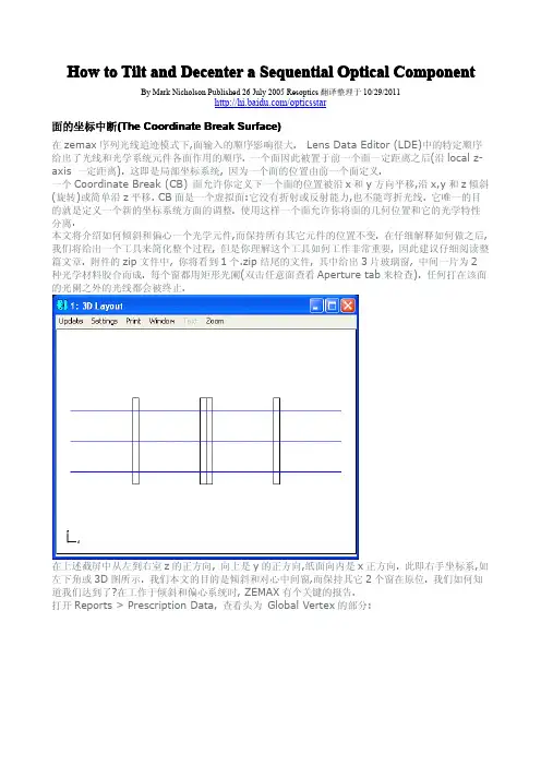
《新编简明英语语言学教程》第二版第4章练习题参考答案Chapter 4 Syntax1. What is syntax?Syntax is a branch of linguistics that studies how words are combined to form sentences and the rules that govern the formation of sentences.2. What is phrase structure rule?The grammatical mechanism that regulates the arrangement of elements (i.e. specifiers, heads, and complements) that make up a phrase is called a phrase structure rule.The phrase structural rule for NP, VP, AP, and PP can be written as follows:NP →(Det) N (PP) ...VP →(Qual) V (NP) ...AP →(Deg) A (PP) ...PP →(Deg) P (NP) ...We can formulate a single general phrasal structural rule in which X stands for the head N, V, A or P.3. What is category? How to determine a word's category?Category refers to a group of linguistic items which fulfill the same or similar functions in a particular language such as a sentence, a noun phrase or a verb.To determine a word's category, three criteria are usually employed, namely meaning, inflection and distribution.若详细回答,则要加上:Word categories often bear some relationship with its meaning. The meanings associated with nouns and verbs can be elaborated in various ways. The property or attribute of the entities denoted by nouns can be elaborated by adjectives. For example, when we say that pretty lady, we are attributing the property ‘pretty’ to the lady designated by the noun. Similarly, the propertie s and attributes of the actions, sensations and states designated by verbs can typically be denoted by adverbs. For example, in Jenny left quietly the adverb quietly indicates the manner of Jenny's leaving.The second criterion to determine a word's category is inflection. Words of different categories take different inflections. Such nouns as boy and desk take the plural affix -s. Verbs such as work and help take past tense affix -ed and progressive affix -ing. And adjectives like quiet and clever take comparative affix -er and superlative affix -est. Although inflection is very helpful in determining a word's category, it does not always suffice. Some words do not take inflections. For example, nouns like moisture, fog, do not usually take plural suffix -s and adjectives like frequent, intelligent do not take comparative and superlative affixes -er and -est.The last and more reliable criterion of determining a word's category is its distribution. That is what type of elements can co-occur with a certain word. For example, nouns can typically appear with a determiner like the girl and a card, verbs with an auxiliary such as should stay and will go, andadjectives with a degree word such as very cool and too bright.A word's distributional facts together with information about its meaning and inflectional capabilities help identify its syntactic category.4. What is coordinate structure and what properties does it have?The structure formed by joining two or more elements of the same type with the help of a conjunction is called coordinate structures.It has (或写Conjunction exhibits) four important properties:1) There is no limit on the number of coordinated categories that can appear prior to the conjunction.2) A category at any level (a head or an entire XP) can be coordinated.3) Coordinated categories must be of the same type.4) The category type of the coordinate phrase is identical to the category type of the elements beingconjoined.5. What elements does a phrase contain and what role does each element play?A phrase usually contains the following elements: head, specifier and complement. Sometimes it also contains another kind of element termed modifier.The role each element can play:Head:Head is the word around which a phrase is formed.Specifier:Specifier has both special semantic and syntactic roles. Semantically, it helps to make more precise the meaning of the head. Syntactically, it typically marks a phrase boundary.Complement:Complements are themselves phrases and provide information about entities and locations whose existence is implied by the meaning of the head.Modifier:Modifiers specify optionally expressible properties of the heads.6. What is deep structure and what is surface structure?There are two levels of syntactic structure. The first, formed by the XP rule in accordance with the head's subcategorization properties, is called deep structure(or D-structure). The second, corresponding to the final syntactic form of the sentence which results from appropriate transformations, is called surface structure (or S-structure).(以下几题只作初步的的成分划分,未画树形图, 仅供参考)7. Indicate the category of each word in the following sentences.a) The old lady got off the bus carefully.Det A N V P Det N Advb) The car suddenly crashed onto the river bank.Det N Adv V P Det Nc) The blinding snowstorm might delay the opening of the schools.Det A N Aux V Det N P Det Nd) This cloth feels quite soft.Det N V Deg A8. The following phrases include a head, a complement, and a specifier. Draw the appropriatetree structure for each.a) rich in mineralsXP(AP) →head (rich) A + complement (in minerals) PPb) often read detective storiesXP(VP) →specifier (often) Qual +head (read) V +complement (detective stories) NPc) the argument against the proposalsXP(NP) →specifier (the) Det +head (argument) N +complement (against the proposals) PP d) already above the windowXP(VP) →specifier (already) Deg +head (above) P +complement (the window) NPd) The apple might hit the man.S →NP (The apple) + Infl (might) +VP (hit the man)e) He often reads detective stories.S →NP (He) +VP (often reads detective stories)9. The following sentences contain modifiers of various types. For each sentence, first identify the modifier(s), then draw the tree structures.(斜体的为名词的修饰语,划底线的为动词的修饰语)a) A crippled passenger landed the airplane with extreme caution.b) A huge moon hung in the black sky.c) The man examined his car carefully yesterday.d) A wooden hut near the lake collapsed in the storm.10. The following sentences all contain conjoined categories. Draw a tree structure for each of the sentences.(划底线的为并列的范畴)a) Jim has washed the dirty shirts and pants.b) Helen put on her clothes and went out.c) Mary is fond of literature but tired of statistics.11. The following sentences all contain embedded clauses that function as complements of a verb, an adjective, a preposition or a noun. Draw a tree structure for each sentence.a) You know that I hate war.b) Gerry believes the fact that Anna flunked the English exam.c) Chris was happy that his father bought him a Rolls-Royce.d) The children argued over whether bats had wings.12. Each of the following sentences contains a relative clause. Draw the deep structure and the surface structure trees for each of these sentences.a) The essay that he wrote was excellent.b) Herbert bought a house that she lovedc) The girl whom he adores majors in linguistics.13. The derivations of the following sentences involve the inversion transformation. Give the deep structure and the surface structure of each of these sentences. (斜体的为深层结构,普通字体的为表层结构)a) Would you come tomorrow?you would come tomorrowb) What did Helen bring to the party?Helen brought what to the partyc) Who broke the window?who broke the window。
Introduction to Non-Sequential Ray Tracing.There are 2 distinct ray-tracing modes in ZEMAX; sequential andnon-sequential. The key differences between sequential andnon-sequential modes are:Sequential mode∙It is mainly used for designing imaging and afocal systems∙Surfaces are defined in the Lens Data Editor∙Ray can only intersect each surface once and has to do it in a specified -sequential- order (i.e. surface #0 then #1 ,#2 …) and hence the namesequential ray tracing∙Ray can only reflect if the surface material type is MIRROR. Partial reflections from refractive surfaces (Fresnel reflections) are accounted for tothe extent of calculating the correct refracted energy, including the effects ondielectric or metallic mirrors∙Each surface has its own local coordinate system. The position of each surface along the optical axis is referenced to the previous surface. In other words, the “Thickness” column in the Lens Data Editor refers to the distance from current surface and not from a global reference pointNon-sequential mode∙It is primarily used for non-imaging applications such as illumination systems and/or stray-light analysis∙Surfaces or volume objects are defined in the Non-Sequential Component Editor∙Mechanical components may be easily imported from CAD programs, so that full Opto-Mechanical analysis may be undertaken∙ A ray can intersect the same object more than once and can intersect multiple objects in any order; hence the name non-sequential∙Each object is referenced to a global coordinate, unless specified otherwise ∙Partially reflected rays can be generated and traced from a refractive interface, in addition to tracing the refracted ray. This is referred to as raysplitting. Hence both the reflected and refracted rays can be traced.∙Imaging-system properties such as stop location, entrance and exit pupil, field, system aperture etc.that exist in sequential systems may not be meaningful innon-sequential systems∙The main analysis feature in non-sequential mode is the detector ray-trace, which gives spatial and angular data on incoherent or coherent rays.In addition, a hybrid mode ("non-sequential with ports" or "mixed-mode") exists in which sequential and non-sequential ray-trace are used in the same system.Full details of non-sequential ZEMAX capabilities are given in chapter 12 of the user manual.Setting up Basic System PropertiesWe will create a non-sequential system with a filament source, a parabolic reflector and a plano-convex lens that couples light into a rectangular lightpipe, as shown in the layout below.We will also trace analysis rays to the detectors to obtain the irradiance distribution at various points in the optical system. Here is what we will finally produce:If ZEMAX is not running, please start it now.By default, ZEMAX starts in sequential/mixed mode. To switch to pure non-sequential mode, open ZEMAX and click File>Non Sequential Mode.Once in pure non-sequential mode, the window title bar of the editor will display the Non-Sequential Component Editor instead of the Lens Data Editor when in sequential mode. The Lens Data Editor is used only in sequential or mixed-mode systems.For this exercise, we will set the system wavelength, specified underSystem>Wavelengths, to 0.587 µm.We will also set the units under System>General Unit tab as follows (default).In addition to radiometric irradiance unit such as Watt.cm-2, you can specify photometric and energy units such as lumen.cm-2 or joule.cm-2. We will choose the default radiometric units for this exercise.Creating the ReflectorInsert a few lines in the non-sequential component editor by pressing the “Insert” key on your keyboard.In the first part of the design, we will create a filament source collimated by a parabolic reflector. We will then place a detector object at some distance +Z and look at the irradiance distribution on a detector.Make the first object a parabolic reflector by double clicking (left clicking) on the “Object type” column of Object 1 in the editor and opening the Object Property window. Under the Type tab set the Type to Standard Surface and click OK.In the editor, type the following parameters in the corresponding column of Standard Surface Object. For some of the parameters, you might have to scroll to the right of the editor to see the title column display the desired parameter name.Material: MirrorRadius: 100Conic: -1 (parabola)Max Aper: 150Min Aper: 20 (center hole in the reflector)All other parameters should be left as defaultYou can open the NSC 3D layout under Analysis>Layout> NSC 3D Layout menu and/or the NSC Shaded model (Analysis>Layout> NSC Shaded model) to see what this reflector looks like.Creating the SourceChange the object #2 type (currently a Null Object) in the editor to Source Filament object by repeating the previous step and choosing Source Filament in the property window.We want the Source Filament to be at the focus of the parabolic reflector to collimate the beam. The filament coil has 10 turns with overall length of 20mm and radius of turn of 5mm.The parameter entered for the Source Filament in the editor should be: Z position: 50 (focus of the parabolic reflector)# Layout Rays 20# Analysis Rays 5000000Length: 20Radius 5Turns 10Update the 3D layout by clicking Update in the NSC 3D Layout menu.The layout shows 20 rays emanating from the source filament, as specified in the # Layout Rays parameter.The source is oriented along the Z axis, but suppose we want to orient it along the X axis; we would need to rotate the source object by 90 degrees about the Y axis. Enter 90 for the Tilt About Y parameter of the source.The default YZ plane view of the layout show the filament being oriented along the X axis, however, the XZ plane view reveals that the filament is shifted towards +X axis. To rotate the layout, change the layout view angle in the Layout settings window (click Settings in the Layout menu). You can also rotate the drawing by pressing the left, right up down arrow key and Page Up and Page Down key on your keyboard.The reason for the decenter is because the rotation axis of the Source Filament is not at the center of the object but at the end. To center the source in the X axis, enter -10 in the X position column.Update the layout and it will now show the desired filament location and orientation. Placing a DetectorNext step is to place a detector object at some distance from the source to study the irradiance distribution at that location.Make the 3rd object in the editor a “Detector Rect” and enter the following parameters.Z position: 800Material: Blank (do not type the word "Blank" but leave the cell empty)X Half Width: 150Y Half Width: 150# X Pixels: 150# Y Pixels: 150Color: 1 (detector displays inverse greyscale)All other parameters as defaultThe YZ plane view (default) of the layout shows:Observe that the layout shows the rays going though the detector. The detector is totally transparent since the material type is air (blank in the editor).Tracing Analysis Rays to the DetectorTo see the optical intensity at the detector, we need to open the Detector Viewer by clicking Analysis > Detectors > Detector Viewer.You will notice that the detector viewer is blank with zero total power, even though we see rays reaching the detector in the layout. The reason is because the rays are traced separately for the layout and for the detector viewer. We need to trace the analysis rays to the detector first to see the result. The number of rays traced to the detect or is specified in the “# Analysis Rays” parameter column of the Source Filament object in the editor, which is usually a large number: 5 million in this case. Remember, layout rays do not affect the Detector Viewer results; only analysis rays do.To trace analysis rays to the detector, open the Detector Control window under Analysis>Detectors>Ray Trace / Detector Control.Always remember to the clear the detector by pressing the Clear Detector button, if you do not wish to add the result from the previous trace to the current one. Press Clear Detectors then Trace button followed by Exit.The detector viewer will display the irradiance distribution, revealing the hotspots caused by the filament source.If your Detector Viewer looks different, open the detector viewer settings window and make sure the settings are as follows.You can also see the detector trace result in the NSC Shaded Model Layout by selecting “Color pixels by last analysis” option in the settings.Adding a Plano-Convex LensNow that we have a source and a reflector, we will add a refractive plano-convex lens 10mm to the right (+Z) of the detector. Insert a line after Detector Rect in the editorand make the type Standard Lens with the following parameter values.Ref Object: 3Z Position: 10Material: N-BK7Radius 1: 300Clear 1: 150Edge 1: 150Thickness: 70Clear 2: 150Edge 2: 150Update the 3D LayoutNotice how we referenced the position of the lens to object 3 (Detector Rect) by entering the value 3 in the Ref Object column and specified the Z position value of 10, instead of referencing to global vertex (Ref Object = 0) and specifying 810mm for theZ position parameter. With the lens positioned referenced to the detector, the lens will always be 10mm to right (+Z) of the detector regardless of the detector position. This is how relative object positions are specified in non-sequential mode.To see how the focused beam looks like, place another detector 650mm to the right (+Z) of the lens with the following parameters.Ref Object: 4Z position: 650Material: BlankX Half Width: 100Y Half Width: 100# X Pixels: 150# Y Pixels: 150Color: 1All other parameters: DefaultUpdate the 3D LayoutOpen another Detector Viewer by clicking Analysis>Detectors>Detector Viewer and make the settings as follows.Now, we are ready to trace analysis rays to the detector again. Since the N-BK7 lens is uncoated, we need to account for the reflection losses (Fresnel reflection), thus needto enable “Use Polarization” opt ion in the Detector Control window. (Note that we are not splitting rays at this time, and so the reflection losses are accounted for, but the reflected energy is not being propagated. Clicking "Split Rays" will create child rays that take the reflected energy away.)The total power, reported in the Detector Viewer is now accounting for reflection losses and bulk absorption in the lens.Adding a Rectangular LightpipeAs a final step, we will add a rectangular acrylic lightpipe 20mm to the right (+Z) of the Detector #5.Add Rectangular Volume object in the editor, after Detector #5, with the following parameters:Ref Object: -1Z position: 20Material: AcrylicX1 Half Width 70Y1 Half Width: 70Z length: 2000X2 Half Width: 70Y2 Half Width: 70All other parameters: DefaultWhen entering the material type Acrylic, you might get the following message. Click Yes and ZEMAX will add to your file the MISC glass catalog, in which the material Acrylic is defined.This time, we have set the Ref Object parameter -1, which represent the previous object in the editor (Object #5 Detector Rect). This is same as typing “5” for this parameter. Specifying relative object using negative number for the Ref Object is useful when group of objects in the editor are to be copied and pasted into the same or different non-sequential component editor.Place another Detector Rect as object #7 in the editor with following parameters. Ref Object: -1 (referenced to Rectangular Volume, using the relative object reference)Z position: 0 (we will change this value later)Material: AbsorbX Half Width: 100Y Half Width: 100# X Pixels: 150# Y Pixels: 150Color: 1All other parameters: DefaultUsing a Pickup Solve to Position the DetectorThe updates 3D layout will show the followingThe material type was set to Absorb to make the detector opaque rather than transparent, evident from the layout.Since we referenced the Detector #7 to the Rectangular Volume and set the Z position as zero, the Detector is located at the front surface of the lightpipe. We want to place this detector 10mm to the right (+Z) of the lightpipe, hence the Z position value should be 2010 mm (thickness of Rectangular Volume + 10). If we change the thickness of the Rectangular Volume to a different value, the Z position of the detector #7 should also be changed. For convenience, instead of typing the value 2010 mm in the editor, we will pla ce a “Pickup solve” for the Z position of the detector. Then the Z position value in the editor will automatically be calculated to be 10 plus whatever the thickness of object 6 is.Double or right click on the Z position parameter of object #7 in the editor to open the solve window.Type the following parameters.The Parameter #0 in the Non-Sequential Component Editor corresponds to the “Material” column, so for the Rectangular Volume object, parameter #3 corresponds to “Z Length”.After pressing OK, a letter “P” will appears next to the parameter in the editor indicating the presence of Pickup solve.Ray-Tracing the Complete SystemOpen a third detector viewer to view detector #7 and re-trace the detector. Remember to use the polarization option and to clear the detectors before tracing the detector, in the Detector Control window.The trace time on a Dell Precision 370 machine running Windows XP Pro, 3.4 GHz Pentium 4 and 1GB of memory is about 2 minutes.The detector viewer shows that the light pipe has effectively removed the hot spots making the irradiance distribution almost uniform.The zipped file of the complete system is included with this article as reference.The NSC Shaded Model can include the detector trace results. For the layout below, multiple-configuration capability of ZEMAX was used to display the system with and without the detector results in the same layout (we will not go into details on how to do this). Users are encouraged to learn about the full non-sequential capacities of ZEMAX by referencing the user manual, reading other knowledge base articles and studying sample files that comes with ZEMAX.Summary and ReferencesThis article has shown how to create and analyze a simple non-sequential system in ZEMAX. In summary:∙There are major differences between the sequential and non-sequential ZEMAX that users need to aware of before attempting to design anon-sequential system∙Layout rays do not affect detector trace results∙To account for Fresnel losses and bulk absorption, the polarization option should be used when tracing analysis rays to the detectorReferences:ZEMAX user Manual。
2024年江苏新高考一卷英语试题2024年江苏新高考一卷英语试题及答案例:How much is the shirt?A.E19.15.B.E9.18.C.E9.15.答案是C.1.What is Kate doing?A.Boarding a flight.B.Arranging a tripC.Seeing a friend off.2.What are the speakers talking about?A.pop star.B.An old songC.A radio program3.What will the speakers do today?A.Goto an art show.B.Meet the mans aunt.C.Eat out with Mark4.What does the man want to do?A.Cancel an order.B.Ask for a receipt.C.Reschedule a delivery5.When will the next train to Bedford leave?A.At 9:45.B.At 10:15C.At 11:00.第二节 (共15小题;每小题1.5分,满分22.5分)听下面5段对话或独白。
每段对话或独白后有几个小题,从题中所给的 A 、B 、C 三个选项中选出最佳选项。
听每段对话或独白前,你将有时间阅读各个小题,每小题5秒钟;听完后,各小题将给出5秒钟的作答时间。
每段对话或独白读两遍。
听第6段材料,回答第6、7题。
6.What will the weather be like today?A.StormyB.SunnyC.Foggy7.What is the man going to do?A.Plant a tree.B.Move his carC.Check the map听第7段材料,回答第8至10题。
Tolerance analysis using Zemax, the case for the small optics.OPTI521, Sooyong Nam AbstractA systematic procedure to perform tolerance analysis of the small optics has presented. To implement thisof this procedure, a typical cell phone camera lens has been chosen to evaluate performance degradation ofthe optical system. This outline could provide a starting point to understand small optics tolerancing and the instructions to use Zemax as a design and tolerancing tool.1. IntroductionA few obvious trends in current consumer electronic devices are small and compact size but performinghigh with very reasonable price. Optics inside those products are not the exception. It is getting thinner buthas to be performing much better than before with higher pixel resolution. As a result of those tight requirements, the tolerances are very tight and challenging. In this article, a systematic procedure for the tolerance analysis by Zemax has presented. The details about the design of three plastic lens elements arenot covered in this article.2. Procedure to perform tolerance analysisThe basic outline of the optical tolerancing procedure has presented in Fig. 1). In this analysis, as small cellphone camera lenses don’t have complicated mechanical focusing features, only those blue-boxed tasks are completed. Pink boxed tasks are done but will not be discussed in this article.(1)Table 1) is specification of required lens. Its F# is 2.8, pixel size is 5.6μm, and required resolution at centeris 125lp/mm. This is typical specification of fixed focus VGA cell phone camera lens. As a merit functionof the sensitivity analysis, 20% MTF drop at 45 lp/mm frequency is used.Table 1) Design specificationSpecification item Required performanceField of view 60 degreesF# 2.8 Number of lens elements 3 plastic lensesPixel size 5.6 μmImage sensor size 3.58mm x 2.69mm@center Resolution 125lp/mm3. Optical layout for cell phone cameraFig. 2) is optical layout of cell phone camera. It has three aspheric plastic lenses, both sides are aspheres and there are two aperture stops between surface 3 and 6. As shown in Fig. 3), the materials are Zeonex E48R and Polycarbonate. Their indices are around 1.45~1.5. It is very clear and stable compare to conventional optical plastic. The total length from first surface to image plane is about 5.3mm and the lens diameters are from 2.6mm to 4.6mm.Fig. 2) Optical layout with 3 plastic aspheric lensesFig. 3) Lens data in Zemax4. Optomechanical layoutFig. 4) is optomechanical layout. Due to dimensional restriction and cost reduction requirement, these are manufactured from plastic injection molding process. All lenses have their own individual mount so that the flange surfaces are stacked together with respect to the bore surface of the barrel. A plastic injection molded aperture stop is located between lens1 and lens2. Lens3 will be located after lens2. Retainer will be glued to the barrel to maintain lens assembly and survived from the shock and keep all required tolerance remained.Fig. 4) Optomechanical layout2 36978Fig. 5) is the part of the drawing that has all the necessary tolerances are specified. At the top left corner, surface power and irregularity tolerances are specified and the note below is the index of refraction. Aspheric equation and their coefficients have described in the box at the top right corner. On the lens drawing, center thickness, element tilt, element decenter, and element spacing tolerances are specified. All these specific numbers are come from tolerance analysis.Fig. 5) Error analysis from the lens element5. Sensitivity table and error budgetFig. 6 and 7 are input data to execute tolerance analysis from Zemax. Perturbed amounts are 1 fringe for radius of each surface(power), 0.01mm for thickness, 0.05 degree for surface tilt, 0.001 for index change, 0.05 degree for element tilt, and 0.010mm for element decenter. Zemax allows us to tolerate surface irregularity by assigning tolerance operand TEZI which is simulating surface by adjusting Zernike coefficient. 0.00005mm is used as RMS surface irregularity.Fig. 6) Tolerance input to the Zemax Fig.7) Tolerance analysis routine in ZemaxAfter completed to define tolerances, the Zemax will generate tolerance table in Fig. 8). Then we can run tolerance analysis routine. From the command box shown in Fig. 7), we can calculate sensitivity to the given merit function.As a merit function to evaluate performance degradation, percentile MTF drop at Ny/2 has selected. Because resolution and contrast is one of the main category to evaluate image quality of the camera. Since this system uses 5.6μm pixel for the image sensor, the Nyquist frequency is 89lp/mm and Ny/2 is 45lp/mm.Fig. 8) Tolerance data editor in ZemaxTable 2 is the result sensitivity table and error budget. Presented percentile MTF drop is from the 0 degree field at 0.632μm wave. Optical schematic has been attached on top the table to identify effects easily. From the analysis result, we can have following results:- Lens 1 and following space : The dominant variables are index change and power tolerance for the surface 2 and surface 3 are second dominant. Thickness and decenter tolerance is not as sensitive as previous three parameters. The effect of surface irregularity, lens1 and 2 spacing, and element tilt are almost negligible. Surface wedge is negligible through the entire system. So it doesn’t need to be taken into consideration for this system.- Lens 2 and following space : Dominant tolerances are power of two surface and spacing between lens 2 and lens 3. Thickness is next dominant one and after then other tolerances are all insensitive. Lens 2 is the least sensitive element.- Lens 3 and space between image plane : Center thickness and space tolerance between lens and image plane are most dominant variables. Power tolerance of the surface 8 is second most sensitive tolerance than others. The rest of the other tolerances are quite forgiving compare to other lenses.The RSS results have been calculated after each lens error and total RSS has calculated based on the error of each lens. The total RSS of system degradation due to tolerated error is 17.7% of MTF drop. Therefore the design specification less then 20% at Ny/2 is achieved.comment3. Nominalvalue4.Perturbation5. MTF6.Sensitivity7.Tolerancesrefraction 1.5312 0.0010 0.0550 55.030.00100 2-3 Thickness(mm) 0.8822 0.0100 0.0283 2.830.01000 2.830.0000 0.0500 0.0001 0.000.10000Decenter(mm) 0.0000 0.0100 0.0131 1.310.02000 1.3941 0.0011 0.0333 30.250.00220 0.0001 0.0001 2.800.00005 0.0500 0.0002 0.000.10000 2.3987 0.0066 0.0410 6.200.01320 0.0001 0.0035 69.360.00005 0.0500 0.0000 0.000.10000 Spacing0.9750 0.0100 0.0006 0.060.01000 2369786. ConclusionAfter completing tolerance analysis for the cell phone camera lens using Zemax, we have following conclusions,a.From the given optical design, optomechanical layout has been presented.b.Actual drawing with tolerance for the lens fabrication has been presented.c.Dominant errors and negligible errors have been clarified after tolerance analysis. Lens thickness,space between lens and power of each surfaces are dominant factors to affect performance.d.Over all tolerance guide line has been met with 17.7% MTF drop at 45lp/mm7. References(1) Robert H. Ginsberg, “Outline of tolerancing (from performance specification to tolerance drawing)”, Optical Engineering, March/April 1981, Vol. 20, No. 2, pp. 175-180(2) Zemax manual and Zemax knowledge base website.。
本周让我们聚焦:序列模式下如何使用全局坐标系在序列模式光学系统中,使用局部坐标系通常更为方便。
然而仍有一些情况适合使用全局坐标系,如在一个具有复杂三维倾斜和偏心系统中处理有限元分析扰动数据。
这篇文章介绍了如何在序列模式中进行局部坐标和全局坐标的转换。
本文用到的示例文件请从以下链接中下载:https:///support/knowledgebaxxxxse/Knowledgebaxxxxse-Attachments/How-to-Work-in-Global-Coordinates-in-a-Sequential/Global.aspx引言序列模式光学系统中,我们常使用局部坐标系,即表面的位置由Z轴上距前一个表面的距离定义。
我们可以利用坐标间断面实现X、 Y轴的偏心以及关于X、Y和Z轴的倾斜。
镜头数据编辑器的工具栏提供了实现常见操作的一系列工具,如添加或删除反射镜和旋转/偏心元件:但有时,使用全局坐标系更为方便。
一个常见的例子是,将光学系统转换到有限元分析中进行振动分析。
从消费电子产品(如数码相机)到星载望远镜和卫星成像透镜,这一分析通常都是由光学设计实现的。
最终我们会得到一组振动引起的扰动数据,而后将这些数据导入OpticStudio中,评估机械位移对光学性能的影响。
在这种情况下,我们需要方便快捷地进行局部、全局坐标系的双向变换。
这篇文章介绍了镜头数据编辑器工具栏上的全局到局部坐标系 (Global To Local) 和局部到全局坐标系 (Local To Global)工具是如何工作的。
初始设计让我们以一个足够复杂但又方便演示的光学系统开始。
附件中包含名为single_prism.zmx的示例文件:在开始之前,我们来花点时间研究一下该示例文件中的光学系统是如何搭建的。
准直光在表面1处进入系统(作为物面),表面2是一个矩形孔径的平面。
表面2相对于表面1倾斜了15°,面之后 (Aflter Surface) 选项,我们设置翻转此面(Reverse This Surface),以便之后的表面回归到原始坐标系中。
ZEMAX Users' Knowledge Base - /kbHow to Tilt and Decenter a Sequential Optical Component/kb/articles/24/1/How-to-Tilt-and-Decenter-a-Sequential-Optical-ComponentBy Mark NicholsonPublished on 07/26/2005This article explains:z What coordinate break surfaces are, and how they workz How to use the Global Vertex report to check your workz Why coordinate break surfaces usually come in pairsz Why coordinate break surfaces have to be co-locatedz How to do all this the easy, simple, fun wayThe article is accompanied by a ZIP archive containing the sample ZEMAX files used. This can be downloaded from the final page of the article.The Coordinate Break SurfaceIn the sequential ray-tracing mode of ZEMAX, the order in which surfaces are entered matters enormously. The order specified in the Lens Data Editor (LDE) gives the exact order in which light interacts with the component surfaces of the optical system.One surface is therefore placed a thickness (a distance along the local z-axis) away from the previous surface. This is known as a local coordinate system, because the location of a surface is specified in terms of the previous surface.A Coordinate Break (CB) surface allows you to specify the location of the next surface as being shifted in x and y, and tilted (rotated) in x, y and z as well as simply shifted in z. The Coordinate Break is a dummy surface: that is, it has no refractive or reflective power and cannot bend rays. Its sole purpose is to define a new coordinate system in terms of the current one. Using such a surface allows you to separate the geometric location of a surface from its optical properties.In this article we will show how to tilt and decenter an optical component while leaving the position of all other components unchanged. After explaining precisely how to do this, we will show a tool that simplifies the whole process, but it is important you understand how the tool works, and so a careful reading of the whole article is advised. In the attached zip file, you will find a file, starting point.zip, which shows three glass windows, the central one of which is two optical materials glued together.Eack of the windows has rectangular apertures applied (double-click on any surface and look at the Aperture tab to verify). Any ray that lands outside the aperture on a surface will be terminated.In the above screenshot, positive z is in the left-to-right direction, positive y is going up the page and positive x is going into the page. This is a right-handed coordinate system, in which z is on your index finger, y on your thumb and x on your middle finger, and your index finger is pointing from left to right, as shown by the coordinate axes in the bottom left-hand corner or the 3D Layout.Our task in this article is to tilt and center the central window while leaving the other two windows in exactly their original locations. How will we know when we have achieved this? ZEMAX has a report which is vital whenever you are working on a tilted or decentered system.Open Reports > Prescription Report, and look at the section headed Global Vertex:The Global Vertex report lists the position and orientation of the vertex of each surface with respect to the Global Coordinate Reference Surface (GCRS). In this design, surface 1 is the GCRS, but any surface may be selected either from the Type tab of the Surface Properties or from the Misc tab of the System Properties dialog boxes.From the Global Vertex report it can be seen that all surfaces are on-axis with respect to the GCRS, as the rotation matrix is a unit matrix for all surfaces and the {x,y} coordinates of each surface is zero. Surface 7 (the front surface of window 3) has {x, y, z} coordinates {0,0,33} with respect to surface 1, the GCRS.The Coordinate Break (CB) surface allows you to specify a decentration in x, decentration in y, tilt in {x, y, z} as well as shift in z (thickness) that affects all subsequent surfaces. It also has an order flag, the purpose of which we will discuss later.Our first task is to decenter the middle window, without disturbing the location of any other surfaces. Decentering a ComponentIn order to decenter the middle window, click anywhere on surface 4 (it has the comment Front Window2) and press the INSERT key on the keyboard. A new surface will be inserted, and all surfaces from the oldsurface 4 onwards will have been renumbered (so that surface 5 now has the comment Front Window2).Now double-click on the new surface 4 and set it to a Coordinate Break surface:Then scroll along to the y-decenter and enter a value of -5 mm. The Layout Plot and Prescription Report show the consequence. All surfaces from the Coodinate Break onwards are decentered by -5 mm.The effects of a CB last until another CB is encountered, therefore two coordinate breaks are usually required: one to implement the tilt/decenter and the other to restore the original axis.To demonstrate this, click on Surface 8 (the front of window 3), press INSERT again and make the new surface a CB. Make the thickness of this surface 10 mm, and make the thickness of surface 7 zero, so that the second CB is colocated with the back of the middle window. Give this CB a decenter in y of +5. You should now have the following (open intermediate step.zmx from the zip if you got lost). {Note that because of the rectangular apertures on the surfaces, rays that miss the middle window are terminated. This is an essential part of the sequential model. If you wish to model a system in which rays that miss themiddle window carry on to hit the third window, you must use non-sequential ray-tracing.}The restoring CB restores the original coordinate axes so that subsequent surfaces are back in their original positions.Setting the values of the restoring coordinate break surface by hand is not good practice, as its easy to forget that the second CB needs to be adjusted whenever the first one is. However, ZEMAX makes it easy to automate: just double-click on the y-decenter of the second CB and choose a Pick-Up solve to lock the value to the first CB, as follows:Do this with the decentration in x, and for the tilt parameters also, but leave the order flag = 0 for both CBs at this time. (This is an error, but we will see why in the next page).You should be able to set any value of decenter in x and y, and ZEMAX will restore the original coordinate system at the second CB. If you got lost, open intermediate step2.zmx from the attached zip archive. We will now move onto tilts.Tilting a componentReset all parameters on the first CB to zero. The parameters of the second CB should automatically set themselves to zero because of the pick-up solves. Then set the tilt-x of the first CB to 20 degrees. At first glance, this looks like all we need to do, but when the Global Vertex report is looked at carefully, it is obvious that something is wrong.A y-decentration of 0.68 mm has been introduced by the x-tilt. This is because the second coordinate break is implemented some distance along z of the new, x-tilted coordinate system. In order that weintroduce a pure tilt with no decentration, there must be zero z-shift between the two CB surfaces. This is achieved by a dummy propagation before the second CB.Insert a dummy surface immediately after the second coordinate break. The second CB currently has a thickness of 10. Set this to 0, and make the thickness of the new dummy surface 10. Now the z-shift between the two CBs is a total of 2 mm, so make the thickness of the surface immediately before the second CB -2, and make the thickness of the second CB +2. This dummy propagation places the two CBs at the same point in space, and so the untilting operation introduces no decentration.The dummy surface has no optical effect because we trace -2 mm in air followed by +2 mm in air, so no rays are bent, no optical path length is added. The dummy surface may be hidden using the "Do Not Draw This Surface" and "Skip Rays From this Surface" controls on the Draw tab of the Surface Properties.However, the way in which the dummy propagation thickness has been set is unsatisfactory. What would happen if the thickness of one of the glass surfaces changed, either by hand or during optimization? The second CB would no longer be correctly placed. The key thing is that the second CB must be at the same position as the first, and ZEMAX has a simple, powerful way to ensure that this condition is always met: a position solve.A position solve sets the surface after it to have a specified distance from another surface. Double-click on the thickness of the surface immediately before the second CB (this currently has a thickness of -2), and in the solve dialog box choose:Note that the position solve lets us go back through any number of surfaces until we get to the first coordinate break Then put a pick-up solve on the thickness of the second CB, that picks up the value of the position solve and multiplies it by -1. Now change the thickness of the glass surfaces between the two CB surfaces. No matter what thickness you enter, the second CB is always exactly co-located with the first, and so can undo it perfectly.Finally, notice one more thing. Set a y-tilt of 30 degrees and an x-tilt of 10 degrees. Note that the second CB no longer undoes the first one perfectly. This is because the order of the tilts matters. If we tilt about x, and then tilt about y in this new tilted position, then we must untilt about y and then untilt about x in order to restore the original coordinate system. This is what the Order flag is for.If the Order flag is zero, the CB surface executes such that decenters are done first, and then tilts in order. If the Order flag is non-zero, the CB executes in reverse order. This meas that a single CB can unstrip any compound tilt/decenter introduced by another other CB that it is co-located with.The final system is included as final system.zmx in the attached ZIP archive. Here is the system, with any number of tilts and decenters, showing that the position of the third window is unaffected . Note the dummy surface has been hidden.But isn't there any easier way to do all this? There is!The Tilt/Decenter Elements ToolThis is the easy way to tilt/decenter an optical element. Re-open starting point.zmx, and then click on Tool > Miscellaneous > Tilt/Decenter Elements, and enter whatever tilt/decentration data you want, for example:Note that this tool does everything we did by hand! Using the tool is highly recommended as the standard technique by which you should tilt or decenter optical components in your system.Summary and ReferencesIn summary, in order to tilt/decenter an optical element in a sequential optical system:z Two coordinate break surfaces are usually required, one to perform the compound tilt/decenter and the other to restore the original axisz The two CB surfaces must be co-located, which is done most easily with a position solvez The decenters and tilts of the second CB must be the exact reverse of the first CB. This is most easily achieved with pick-up solvesz The order in which decenters and tilts are applied by the second CB must be the reverse of that used by the first. The Order flag is used to achieve thisz The Tilt/Decenter Element Tool is the easiest way to achieve all this in one step, and is strongly recommended.z Check the results with the Global Vertex section of the Prescription Report to ensure surfaces are placed where you expect them to be.ReferencesThere are no external references for this article.。