Design and Control for LCL-Based Inverters with Both Grid-Tie and Standalone Parallel Operations Chien-Liang Chen, Jih-Sheng Lai, Yu-Bin Wang, Sung-Yeul Park, and Hide Miwa
Virginia Polytechnic Institute and State University
Future Energy Electronics Center
415 Whittemore Hall, Blacksburg, VA 24061-0111, USA
jlchen99@https://www.doczj.com/doc/7910096803.html,, laijs@https://www.doczj.com/doc/7910096803.html,, ybwang@https://www.doczj.com/doc/7910096803.html,, supark@https://www.doczj.com/doc/7910096803.html,, and hmiwa1@https://www.doczj.com/doc/7910096803.html,
Abstract—The inductor-capacitor-inductor (LCL) filter allows higher noise attenuation and universal output in which a power conditioning system or an inverter can operate in both grid-tie and standalone modes. In this paper, the LCL filter design considerations including sensor position selection and component selections are discussed for single-phase paralleled inverters operating in both grid-tie and standalone modes. For grid-tie mode operation, each inverter is operating under a single current loop with proportional-resonant controller and admittance path compensation to reduce the steady-state error by providing a high gain at the fundamental frequency. For standalone mode operation, one of the inverters is implemented with a dual-loop controller to regulate the output voltage while the rest inverters operate in single current-loop controller with communication channels in between to ensure the uniformity of current sharing. Both the simulation and experimental results verify that the designed controllers are capable of paralleling inverter operation in grid-tie and standalone modes by adapting to different controller settings while keeping the same hardware setup.
Keywords-LCL filter, grid-tie inverter, dual-loop control, PR controller, parallel inverter, admittance compensation.
I.I NTRODUCTION
The parallel inverter systems have demonstrated many advantages compared to a single high-power inverter [1-8]. For example, an inverter can be designed in modular manner which allows the system capacity to be multiplied and the reliability can be greatly improved with redundancy. Parallel inverter operation has been a major topic in uninterruptible power system (UPS) applications where the design is focused on the standalone operation, and the output stage is typically an inductor-capacitor (LC) filter. When connecting the paralleled inverters to utility grids, the capacitor becomes redundant, and thus either a pure inductor (L) or an LCL filter can be used as the inverter output stage. Compared with the L filter, the LCL filter is more attractive [9] because it can not only provide higher high-frequency harmonics attenuation with the same inductance value, but also allow the inverter to operate in both standalone and grid-tie modes, which makes it a universal inverter for distributed generation applications such as fuel cell and photovoltaic power conditioning system (PCS).
Major factors that were used in LCL design considerations include inductor current ripple magnitude and reactive power consumption in capacitor [10], the range of LCL resonant frequency, and the total inductance value of LCL filter [11]. In this paper, the sensor position selection and the universal application in both grid-tie and standalone modes are added as the LCL design factors.
The compliance of interconnect standards IEEE 1547 and 1547.1 [12,13] and their current harmonic limits can also be used in the LCL design criteria. However, the cause of inverter harmonic distortions were mainly found in nonlinear effects such as nonlinear device voltage drop, dead time, limited PWM resolution and lack of stiffness in dc link [14]. The controller with high gain at the harmonic frequencies such as proportional-resonant (PR) controller [15] and direct-quadrant (DQ) frame current controller [16,17] can be potential candidates to alleviate such harmonic distortions.
In addition to harmonic concerns, the controller design for parallel inverter systems must consider stability and steady-state error issues. In general, parallel inverters are designed in standalone mode for UPS and distributed generation (DG) systems that supply regulated output voltages when grid is not available. Most reported standalone inverter systems use a LC filter and proportional-integral (PI) controller in their control loops [18-20]. In [18,19], multiple feedback loops were proposed to improve the output voltage performance and to damp the poles of LC filter. In [20], feedback, feed-forward, and nonlinear controls were considered for the entire UPS control system. These parallel inverter systems, however, are usually designed with LC filter [1-8] which will have difficulties in grid-tie operations due to the undetermined resonant frequency caused by the change of grid-side source impedance [21]. The design of parallel inverters also needs to consider the current sharing capability [5-6] and the communication [7-8] among paralleled inverters. In [5], some current-sharing schemes for parallel inverter systems including master-salve control, current-limit control, and circular-chain control are examined and compared. In [6], a current-weight-distribution control was proposed to allow inverters in parallel with different output current capability. In [7], the controller area network (CAN) communication interface is utilized in a parallel inverter system to obtain a higher reliability. In [8], a new voltage and frequency droop control for parallel inverter systems is proposed to allow a robust current sharing without communication between inverters.
In this paper, the paralleled inverters adopt the LCL filter as the output stage to allow the inverter to operate in both grid-tie
and standalone modes. The design procedure of LCL filter in this universal inverter including sensor position and component selection will be discussed. By selecting the filter capacitor voltage and inverter-side inductor current as control feedbacks, the controller of LCL-filter inverter can be easily designed. For grid-tie operation, the current loop employs a PR controller and admittance compensation to achieve high loop gain at the fundamental frequency and to eliminate negative power flow transient during start-up. For standalone operation, one of inverters is selected to incorporate a voltage loop in a dual-loop control system with PR-controller on the voltage loop and a P-controller on the current loop to limit current magnitude under transient, to enhance voltage loop stability, to allow equal current sharing, and to reduce voltage steady-state error. The rest of inverters operate in grid-tie mode with only current loop control to share the load current. Both the simulation and experimental results verify that the designed controllers are capable of paralleling inverter operation in grid-tie and standalone modes by adapting to different controller setting while keeping the same hardware setup.
II. LCL D ESIGN C ONSIDERATIONS
A. System Configuration of LCL-Based Inverter
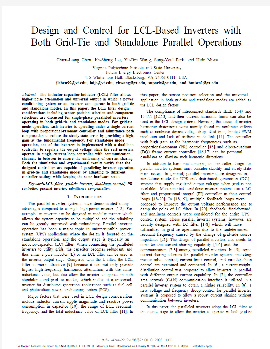
Fig. 1(a) shows the system configuration of an LCL filter inverter operating in the grid-tie mode. Depending on the input voltage level, if the input voltage V in is low and highly unregulated such as fuel cell and PV source, a dc-dc converter is needed before the inverter stage. The inverter output inductor L i , the filter capacitor C f , and the grid-side inductor L g constitute the LCL filter of the inverter. In grid-tie applications, the load is normally modeled as a constant voltage source v s in series with a source impedance L s . Because the grid voltage is known, the way to control the power sending to the grid is to control the inverter output current with current-mode control. Fig. 1(b) represents the LCL inverter used for the standalone operation. On the other hand, most of the standalone loads require the output voltage to be regulated to supply the loads with a desired voltage.
s V
(a)
V
(b)
Fig. 1. (a) LCL based inverter in grid-tie application, and (b) LCL based
inverter in standalone application.
B. Sensor Position Selection for the LCL-Based Inverter First of all, the grid-side voltage v g needs to be sensed for synchronization in grid-tie operations. Next, the capacitor voltage v ac needs to be sensed to regulate output voltage in standalone mode operations. In addition, by selecting the v ac and inverter-side-inductor current i ac as feedback signals instead of v g or grid-side inductor current i g , the duty-cycle-to-output-current transfer function in grid-tie mode will be a first-order system which will greatly simplify the controller design [9]. Furthermore, compared to the current sensor signal i g , feedback of current i ac not only allows the sensor to be easily integrated into the inverter but also reduces the noise in the sensor conditioning circuit because the physical sensor location is closer to the controller board.
C. Selection of Inverter-Side Inductor L i
The selection of the inverter-side inductor L i should compromise the output current performance, system cost, size, and efficiency. For example, with a higher L i value, lower current ripple can be obtained and higher controller gain can be designed to obtain better current performance. Using i ac as the feedback current signal, the simplified duty-cycle-to-current transfer function of an LCL inverter G id (s ) can be expressed in (1).
i dc ac id sL V s d s i s G ==)()()( (1) Here d is the inverter duty cycle, and V dc is the dc link voltage. However, higher inductance value requires higher cost and occupies larger volume. As for the efficiency, higher inductance allows lower current ripple in the inductor L i , which decreases core losses of the inductor. On the other hand, higher inductance value increases the winding loss for longer wire required. The total inductor losses depend on the core materials, core structures, wires, and winding methods.
D. Selection of the Filter Capacitor
If the inverters are implemented only for grid-tie applications, the selection of C f can be determined by limiting the reactive power consumed in C f [10,11]. On the other hand, in the design of universal inverters, the selection of the filter capacitor will be determined by the required voltage ripple damping because the inverter-side inductor L i and the filter capacitor C f will form a second-order filter that provides a -40dB/dec attenuation after the resonant frequency of this L i -C f filter.
E. Selection of the Grid-Side Inductor L g
For the grid-tie inverter shown in Fig. 1(a), the transfer function from duty cycle d to i ac can be derived in (2). ()()2()
()
()1ac dc
i g s i g s f i g s i s V d s L L L s L L L s C L L L =????+????+++??????++????????
(2)
As compared to (1), the denominator of (2) has two more resonant poles that may cause the stability issues. In [21], this resonant frequency was limited in the range neither close to the
current cross-over frequency nor close to the switching frequency to avoid resonance issues. After L i and C f are determined, L g needs to be selected so that the resonant frequency is in a proper frequency range to ensure the stability.
III. P ROPORTIONAL -R ESONANT C ONTROLLER FOR
G RID -T IE I NVERTER O PERATION
The control object in grid-tie operation is its output current because the output voltage is already determined by the grid. The control system shown in Fig. 2 employs the voltage across
the f iltering capacitor , v ac and the current of the inverter-side inductor , i ac as the f eedback signals. Such an arrangement allows the first-order control-to-current transfer function G id (s ) shown in (1) to be used for controller design.
operation.
As indicated in [9], capacitor voltage v ac introduces an
undesired current, and its relationship can be expressed in (3). Here G iv (s) can be considered as an intrinsic admittance, which causes a negative current flow and can damage the system by overcharging the dc-link capacitors.
i
Li ac ac iv sL r s v s i s G +=
=1)()()( (3) Here the L i and r Li are the inverter-side inductance and its
equivalent resistance, respectively. This undesired admittance
term G iv (s) can be eliminated by an admittance compensation,
and thus allowing the following duty-cycle-to-output-current
G id (s) to be used in the controller design .
i Li dc ac id sL r V s d s i s G +=
=)()()( (4) Equations (4) and (1) are essentially the same except the (1) neglects the resistive component r Li . For the system under test, V dc = 420V, r Li = 80m ?, and L i = 1mH. Negligence of r Li
should not impact the controller design. The open current loop gain G ioloop (s) controlled inverter can be obtained in (5).
()*()**()ioloop m id i lf G s F G s H G s =
Here G lf (s) is the low-pass filter combination in the hardware which includes a second-order low-pass filter at 48 kHz and a first-order anti-aliasing filter at 9.6 kHz. H i is the current feedback gain with a 34.133 magnitude, and F m is the DSP modulation gain with a magnitude of 1/1250. The design purpose of the current-controlled inverter is to provide an output current that tracks the external command as close as possible, a PR controller shown in (6) is utilized to provide a high loop gain at the fundamental frequency [15].
22
12()2c r i p c k s
G s k s s ωωω=+++ (6) Here k p is the proportional gain, k r is the resonant gain, ωc is the equivalent bandwidth, and ω1 is the fundamental angular frequency. With the designed controllers, the compensated loop gain T i (s) can be represented in (7).
()()*()i i ioloop T s G s G s = (7) By choosing k p = 0.78, k r = 97.5, ωc = 10 rad/second, and
ω1 = 377 rad/second in G i (s), the Bode plots of G ioloop (s) and T i (s) can be shown in Fig. 3.
M a g n i t u d e (d B )
10
101010
4P h a s e (d e g )Frequency (Hz) Fig.3. The Bode plots of compensated current loop gain T i (s) and current open loop gain G ioloop (s). IV. V OLAGE D UAL -L OOP C ONTROLLR FOR
S TANDALONE I NVERTER O PERATION A. Control Block Diagram
As shown in Fig. 4, the inverter is controlled in a dual-loop
voltage control [18,19] to ensure system safety and enable
current sharing capability among parallel inverters. In this
dual-loop controller, a current inner loop damps the LC
resonance pole while a voltage outer loop regulates the output
voltage.
standalone operation.
B. Inner Current Controller Design
Because of the same inverter hardware setup, the current open loop transfer function G ioloop (s) is the same as that shown in (5). However, the design goal of the current loop in a dual-loop control is to have a high loop bandwidth with enough stability margin rather than to reduce the current steady-state error by providing a high gain at fundamental frequency. With
the first-order loop transfer function G ioloop (s), this current controller is only a simple proportional gain with a software
low-pass filter shown in (8). ()0.5()
SWF
i SWF G s s ωω=+ (8)
Even though the control system does not contain any resonant poles by carefully selecting the sensor positions, the LCL filter hardware does contain resonant poles that could cause resonance on output voltage and current, as indicated in (2). The LCL parameters are L i = 1 mH, C f = 6.8 μF, L g = 0.22 mH which results in a resonant frequency at 4.54 kHz. Thus a 1.5 kHz software first-order low-pass filter is designed to damp possible oscillations at outputs. With the designed current controller, the compensated current loop gain T i (s ) is shown in (9). The Bode plots of T i (s) and G ioloop (s) can be shown in Fig. 5.
T i (s) = G i (s)?G ioloop (s) (9)
1010
10104
P h a s e (d e g )M a g n i t u d e (d B )
Frequency (Hz)
Fig.5. The Bode plots of compensated current loop gain T i (s) and current open
loop gain G ioloop (s).
C. Outer Voltage Controller Design
After closing the inner current loop, the outer open voltage
loop gain can be expressed in (10).
G voloop (s) = G icloop (s)*G vi (s)*H v *G lf (s) (10)
Here H v is the voltage sensor feedback gain, which is 5.12 in the test case. G icloop (s ) and G vi (s ) are the current closed loop gain and output current to output voltage transfer function, respectively. Equation (11) expresses the closed-loop gain of the inner current loop, G icloop (s ). ()**()()1()i m id icloop i G s F G s G s T s =+
Assume that the load is a pure resistive load with a R o value in Fig. 1(b), the output current to output voltage transfer function G vi (s) can be represented in (12).
()
211211()**()
,,,1
1,,g z vi g f o
z p p g o g g f
L s G s L C s p s p R L R a b c L L C ωωωω+=
++==?????
=== (12) The design goal of a dual-loop voltage controller is to obtain a high gain at the fundamental frequency while providing enough bandwidth and stability margin. As shown in (13), a PR controller is adopted here to eliminate the steady-
state error by providing a high gain at the fundamental frequency.
22
12()(2c r v p c k s
G s k s s ωωω=+
++ (13)
With 20% load as the design plant, a PR controller is designed to have k p = 0.02, k r = 12, c = 10 rad/s, and 1 = 377 rad/s. The resulting Bode plots of the compensated voltage loop gain T v (s) = G v (s)*G voloop (s) along with the uncompensated voltage loop gain G voloop (s) are shown in Fig. 6.
10M a g n i t u d e (d B )
10
10104
P h a s e (d e g )
Frequency (Hz)
Fig.6. The Bode plots of compensated voltage loop gain T v (s) and voltage open loop gain G ioloop (s) in a dual loop controlled inverter at 20% rated power.
V. P ARALLEL I NVERTERS WITH LCL F ILTERS
UNDER S TANDALONE M ODE
A. System Configuration
The parallel inverter system under standalone has the same hardware configuration as that under grid-tie mode
configuration except that the load is replaced with a source.
Fig. 7 shows the entire system diagram. In this system, one of the inverters needs to be operating in dual loop control and serve as the voltage reference or the grid voltage source. The rest of inverters will be operating in grid-tie mode, and a single current loop will serve the control purpose.
Load
V in-V in-V Fig. 7. Hardware configuration of paralleled LCL based inverters.
The selection of the inverter running in dual-loop mode or
single-loop mode is determined by the upper level command line, which comes from a CAN bus. Fig. 8 shows the control system diagram with multiple inverters in parallel. Here
inverter 1 operates in dual loop and provides the voltage reference. Inverter 2 and the rest will lock the phase to the reference voltage and operate in single current loop.
Fig. 8. Control block diagram of a paralleled LCL inverter system.
B. Current Sharing and Synchronization through CAN Bus
In order to share the current between inverters, the CAN bus is utilized to ensure a reliable communication interface [7]. The simplest way to transmit the current reference is to send the current reference directly in ac quantity. However, this method is not practical for the increasing phase delay in ac signal if the transmission length is too long which limits the transmission speed of the CAN interface.
In order to overcome the phase delay in ac signal, the transmission signal is the magnitude of i ref1 in dc quantity. The current reference magnitude information shares the current evenly which minimizes the thermal stress of whole system. The phase is synchronized with a phase-locked loop control, similar to the grid-tie control system. The automatic phase adjustment block shown in Fig. 8 is to adjust the phase information of current reference i ref2 automatically by monitoring the phase difference of i ac2 and v ac2.
VI.I MPLEMENTATION R ESULTS
A. Experimental Setup
The hardware setup consists of two 5-kW power conditioning systems. Each PCS consists of a dc-dc converter to boost the low-voltage input 48 V to 400 V and a dc-ac inverter that produces 208 V ac output for the grid connection. The source of the dc-dc converter can be a fuel cell or a photovoltaic, but for this testing, a 60-V, 20-kW fuel cell simulator was used to serve as the source. Each PCS is packaged in a standard 19” rack-mount case with power connection on the back panel, and the DSP controller on the front panel. Fig. 9 shows the photograph of the hardware setup with two identical PCS’s sitting side by side.
dc-dc converter dc-ac inverter
filter board
PCS-1
PCS-2
Fig. 9. Photograph showing two parallel connected PCS’s packaged in
standard rack-mount cases.
B. Grid-Tie Mode Operation
Fig. 10(a) shows the simulation results of the LCL-filter inverter running in current-mode control with PR controller and admittance compensation. The results show that the output current follows a 32-A peak command current very well because of a high loop gain at the fundamental frequency. Fig. 10(b) shows the experimental results under 32-A peak current command in the grid-tie condition. Waveforms indicate that the output current well follows the command, which suggests the current loop PR controller with admittance compensation provides a high loop gain at the fundamental frequency to eliminate the steady-state output error.
Time
100ms150ms200ms
I(Lg)
-40A
0A
40A
SEL>>
V(Vac)- V(Vb0)
-400V
0V
400V
v
ac
i
g
(a)
t:10ms/div
20A
300V
v ac
i g
(b)
Fig. 10. Current loop implementation results at 4.85kW (a) Pspice simulation result at 32A i ref, pk, , and (b) experimental result at 32A i ref, pk.
C. Standalone Mode Operation Fig. 11(a) and Fig. 11(b) show the simulation and experimental results of the duel-loop controlled LCL-filter
inverter with a PR-controller based outer voltage-loop and a P-controller based inner current-loop operation. The output voltage v ac is 215 V rms, and the output current i load is 24.2 A
rms. The power output of 5.2-kW goes into a pure resistive load in both simulated and tested cases. The simulation includes all the dynamics of system transfer function and
controller blocks shown in Fig. 4. Again, the experimental result agrees with the simulation result very well.
SEL>>Time 100ms 125ms
150ms 175ms
200ms
I(RLoad)
-40A
0A
40A V(Vac1)- V(Vb01)
-400V
0V
400V
(a)
t :10ms/div
300V
20A
v ac
i load
(b)
Fig. 11. Voltage dual-loop results at 215V v ac, rms , 5.2kW (a) Pspice simulation
result, and (b) experimental result.
Fig. 12 shows the simulation and experimental results of the paralleled inverters supplying to a 7.6 kW load. Load voltage v load and total current i load are the waveforms observed at the load terminal. Current i out1 and i out2 are monitored at the individual inverters. Both simulation and experimental results indicate that output currents are in phase between two inverters, and both parallel inverters share current evenly to supply the load together. With the observation of total current i load being equal to the sum of i out 1 and i out 2, one can easily conclude that there is no circulating current in between the dual-loop controlled and single-loop controlled inverters. The phase-locked loop and automatic phase adjustment control work effectively.
The even distribution of current between paralleled inverters also indicates that the CAN communication, that transmits the reference current magnitude to different PCS’s
works well, and the proposed design should allow modular inverter design for a high power paralleled inverter system.
SEL>>
Time
100ms 125ms
150ms 175ms
200ms
I(Lg_i)
-80A 80A
I(Lg_v)
-80A
0A 80A
I(RLoad)-80A
0A
80A
V(Vload)- V(Vb01)-400V
0V 400V
i out1
i out2
(a)
v load i load i out1t :10ms/div
40A
i out2
40A
40A
(b)
Fig.12. Parallel inverters operation at 215V v load, rms , 7.6kW (a) Pspice
simulation result, and (b) experimental result.
VII. C ONCLUSION
Complete design and implementation results of a paralleled power conditioning system operating in both grid-tie and standalone modes were presented in this paper. Key design features of the proposed inverter system are summarized as follows.
1. Design of LCL filter
This paper suggested design considerations on current ripple, stability, output performance, sensor location, noise, and ease of controller design. 2. Design of dual- and single-loop controllers
For grid-tie operation, a single current loop controller design with PR controller and admittance compensation is proposed to reduce the steady-state error while maintaining system stability. For standalone operation, a dual-loop control system with PR-controller for outer
voltage loop and a P-controlled for inner current loop is
proposed to limit peak current magnitude under
transient, enhance voltage loop stability, and reduce
voltage steady-state error.
3.Design of synchronization and equal current sharing
The synchronization is implemented with PLL and an
automatic phase adjustment to synchronize the output
currents among different inverters. The CAN bus is
adapted as upper level commander to specify one unit to
operate in dual loop control and to transmit current
reference command magnitude to individual inverters. Simulation and experimental results show that the designed inverters are capable of parallel operation in both grid-tie and standalone modes by adapting to different controller sets with the same hardware setup. The LCL filter based inverter controlled with the proposed single- and dual-loop controllers for different operating modes shows stable output waveforms. The output current is equally shared among different inverters without noticeable circulating current by the use of the proposed synchronization and upper level control methods. The successful parallel operation results suggest that the proposed design with LCL filter based inverter, mix of dual- and single-loop voltage and current controllers, PLL synchronization and CAN bus communication architecture can be extended to microgrid or smartgrid applications where both the grid-tie and standalone operations are needed.
A CKNOWLEDGMENT
The authors would like to thank Mr. M. H. Lin and his group of Tatung System Technologies, Taipei, Taiwan for both financial and technical supports of the project.
R EFERENCES
[1]S. J. Chiang, C. M. Liaw, W. C. Chang and W. Y. Chang, “Multi-module
parallel small battery energy storage system,” IEEE Trans. Energy Conversion, vol. 11, pp. 146-54, Mar. 1996.
[2]J. F. Chen, C. L. Chu, and C. L. Huang, “The parallel operation of two
UPS by the coupled-inductor method,” in Proc. of IEEE International Symposium of Industrial Electronics, vol. 2, May 1992, pp. 733-736. [3]J. F. Chen, and C. L. Chu, “Combination voltage-controlled and current-
controlled PWM inverters for UPS parallel operation,” IEEE Trans.
Power Electronics, vol. 10, pp. 547-558, Sep. 1995.
[4]J. F. Chen, Y. C. Kuo, and T. J. Liang, “Voltage and current hybrid
controlled PWM inverters using variable structure control,” in Proc. of IEEE PEDS, vol. 2, July 1999, pp. 1010-1014. [5]T.-F. Wu, Y.-K. Chen and Y.-H. Huang, “3C strategy for inverters in
parallel operation achieving an equal current distribution,” IEEE Trans.
Industry Applications, vol. 47, pp. 273-281, April 2000.
[6]T. F. Wu, T.-E Wu, H.-M. Hsieh, and Y.-K. Chen, “Current Weighting
Distribution Control Strategy for Multi-Inverter Systems to Achieve Current Sharing,” IEEE Trans. Power Electronics, vol. 22, pp. 160-168, Jan. 2007.
[7] C. Zhang, G. Chen, Z. Guo, and W. Wu, “An alternating-master-salve
parallel control research for single phase paralleled inverters based on CAN bus,” in Proc. of IEEE IPEMC, vol. 1, Aug. 2006, pp. 1-5.
[8]K. D. Brabandere, B. Bolsens, J. V. D. Keybus, A. Woyte, J. Driesen, R.
Belmans, “A Voltage and Frequency Droop Control Method for Parallel Inverters,” IEEE Trans. Power Electronics, vol. 22, pp. 1107-1115, July 2007.
[9] C.-L. Chen, S.-Y. Park, J.-S. Lai, and S.-Y. Moon, “Admittance
compensation in current loop control for a grid-tie LCL fuel cell inverter,” in Proc. of IEEE PESC, Orlando FL, June 2007, pp. 520-526. [10]T. C. Wang, Z. H. Ye, G. Sinha, and X. M. Yuan, “Output filter design
for a grid-interconnected three-phase inverter,” in Proc. of IEEE PESC, Acapulco, Mexico, June 2003, pp. 779-782.
[11]M. Liserre, F. Blaabjerg, and S. Hansen, “Design and control of an LCL-
filter-based three-phase active rectifier,” IEEE Trans. Industry Applications, vol. 41, pp. 1281-1291, Oct. 2005.
[12]IEEE Standard for Interconnecting Distributed Resources with Electric
Power Systems, IEEE Standard 1547, 2003.
[13]IEEE Standard Conformance Test Procedures for Equipment
Interconnecting Distributed Resources with Electric Power Systems,
IEEE Standard 1547.1, 2005.
[14]T. Abeyasekera, C. M. Johnson, D. J. Atkinson, and M. Armstrong,
“Suppression of line voltage related distortion in current controlled grid connected inverters,” IEEE Trans. Power Electronics, vol. 20, pp. 1393-
1401, Nov. 2005.
[15]R. Teodorescu, F. Blaabjerg, U. Borup, and M. Liserre, “A new control
structure for grid-connected LCL PV inverters with zero steady-state error and selective harmonic compensation,” in Proc. of IEEE APEC, Anaheim CA, March 2004, pp. 580-586.
[16] A. Roshan, R. Burgos, A. C. Baisden, F. Wang and D. Boroyevich, “A
D-Q frame controller for a full-bridge single phase inverter used in small distributed power generation systems,” in Proc. of IEEE APEC, Anaheim CA, Feb. 2007, pp. 641-647.
[17]R.-Y. Kim, S.-Y. Choi, and I.-Y. Suh, “Instantaneous control of average
power for grid tie inverter using single phase D-Q rotating frame with all pass filter,” in Proc. of IEEE IECON, Busan, Korea, Nov. 2004, pp. 274-
279.
[18]N. M. Abdel-Rahim and J. E. Quaicoe, “Analysis and design of a
multiple feedback loop control strategy for single-phase voltage-source UPS inverters,” IEEE Trans. Power Electronics, vol. 11, pp. 532-541, July 1996.
[19]W. Yao, C. Zheng, M. Chen, and Z. Qian, “Analysis and research of a
multiple-loop control strategy for single-phase UPS inverters,” in Proc.
of IEEE PEDS, vol. 1,Jan. 2006, pp. 628-632.
[20]H. Deng, R. Oruganti, D. Srinivasan, “Modeling and control of single-
phase UPS inverters: a survey,” in Proc. of IEEE PEDS, Kuala Lumper, Malaysia, Nov. 2005, pp. 848-853.
[21]M. Liserre, R. Teodorescu, and F. Blaabjerg, ”Stability of grid-connected
PV inverters with large grid impedance variation,” in Proc. of IEEE PESC, Aachen, Germany, June 2004, pp. 4773-4779.
四桥臂三相逆变器的控制策略 阮新波严仰光 摘要提出了一种新型的三相四线逆变器,它有四个桥臂,第四个桥臂用来构成中点,从而省去了三相三桥臂逆变器中的中点形成变压器,减小了逆变器的体积和重量。针对这种逆变器,本文提出了一种电流调节器,它根据三相滤波电感电流和给定电流的误差值最大的那相选择逆变器的开关模态。为了消除输出相电压的静态误差,本文讨论 了一种基于PI调节器改进的电压调节方案。仿真结果表明,本文的思路是可行的。本 文为构造大功率、高效率的三相四线逆变器提供了可靠的理论基础。 关键词:三相逆变器控制策略 The Control Strategy for Three-Phase Inverter with Four Bridge Legs Ruan Xinbo Yan Yangguang (Nanjing University of Aeronaut ics & Astronautics 210016 China) Abstract A novel three phase inverter with four bridge legs i s presented in this paper.The inverter eliminates the neutral forming transforme r by adding a bridge leg to form neutral point to provide balanced voltages to a ny kinds of three phase loads.The principle of the inverter is analyzed,and a ne w current regulator,which chooses switching modes a ccording to the maximum cur rent error of filter inductance current and the reference current is proposed.Th e modified voltage regulator on the basis of PI regulator is proposed to elimina te output voltage static error under any load conditions. Keywords:Three-phase Inverters Control strategies 1 引言 三相逆变器一般是采用三个桥臂组成的拓扑结构,为了给不对称负载供电,必须在 输出端加入一个中点形成变压器(Neutral Formed Transformer,NFT),如图1所示。中点形成变压器是变比为1的自耦变压器,工作频率为输出交流电的频率,体积和重 量很大,而且体积和重量随着负载不对称的程度变化而变化,不对称度越大,NFT的体积重量也就越大。
逆变电源广泛运用于各类:电力、通讯、工业设备、卫星通信设备、军用车载、医疗救护车、警车、船舶、太阳能及风能发电领域。 在电路中将直流电转换为交流电的过程称之为逆变,这种转换通常通过逆变电源来实现。这就涉及到在逆变过程中的控制算法问题。 只有掌握了逆变电源的控制算法,才能真正意义上的掌握逆变电源的原理和运行方式,从而方便设计。在本篇文章当中,将对逆变电源的控制算法进行总结,帮助大家进一步掌握逆变电源的相关知识。 逆变电源的算法主要有以下几种。 数字PID控制 PID控制是一种具有几十年应用经验的控制算法,控制算法简单,参数易于整定,设计过程中不过分依赖系统参数,鲁棒性好,可靠性高,是目前应用最广泛、最成熟的一种控制技术。它在模拟控制正弦波逆变电源系统中已经得到了广泛的应用。将其数字化以后,它克服了模拟PID控制器的许多不足和缺点,可以方便调整PID参数,具有很大的灵活性和适应性。与其它控制方法相比,数字PID具有以下优点: PID算法蕴涵了动态控制过程中过去、现在和将来的主要信息,控制过程快速、准确、平稳,具有良好的控制效果。 PID控制在设计过程中不过分依赖系统参数,系统参数的变化对控制效果影响很小,控制的适应性好,具有较强的鲁棒性。 PID算法简单明了,便于单片机或DSP实现。 采用数字PID控制算法的局限性有两个方面。一方面是系统的采样量化误差降低了算法的控制精度;另一方面,采样和计算延时使得被控系统成为一个具有纯时间滞后的系统,造成PID控制器稳定域减少,增加了设计难度。 状态反馈控制 状态反馈控制可以任意配置闭环控制系统的极点,实现了逆变电源控制系统极点的优化配置,有利于改善系统输出的动态品质,具有良好的瞬态响应和较低的谐波畸变率。但在建立逆变器的状态模型时将负载的动态特性考虑在内,因此状态反馈控制只能针对空载和已知的负载进行建模。由于状态反馈控制对系统模型参数的依赖性很强,使得系统的参数在发生变化时易导致稳态误差的出现和以及动态特性的改变。例如对于非线性的整流负载,其控制效果就不是很理想。 重复控制
https://www.doczj.com/doc/7910096803.html,/ 逆变电源广泛运用于各类:电力、通讯、工业设备、卫星通信设备、军用车载、医疗救护车、警车、船舶、太阳能及风能发电领域。 在电路中将直流电转换为交流电的过程称之为逆变,这种转换通常通过逆变电源来实现。这就涉及到在逆变过程中的控制算法问题。 只有掌握了逆变电源的控制算法,才能真正意义上的掌握逆变电源的原理和运行方式,从而方便设计。在本篇文章当中,将对逆变电源的控制算法进行总结,帮助大家进一步掌握逆变电源的相关知识。 逆变电源的算法主要有以下几种。 数字PID控制 PID控制是一种具有几十年应用经验的控制算法,控制算法简单,参数易于整定,设计过程中不过分依赖系统参数,可靠性高,是目前应用最广泛、最成熟的一种控制技术。它在模拟控制正弦波逆变电源系统中已经得到了广泛的应用。将其数字化以后,它克服了模拟PID控制器的许多不足和缺点,可以方便调整PID参数,具有很大的灵活性和适应性。与其它控制方法相比,数字PID具有以下优点:
https://www.doczj.com/doc/7910096803.html,/ PID算法蕴涵了动态控制过程中过去、现在和将来的主要信息,控制过程快速、准确、平稳,具有良好的控制效果。 PID控制在设计过程中不过分依赖系统参数,系统参数的变化对控制效果影响很小,控制的适应性好,具有较强的鲁棒性。 PID算法简单明了,便于单片机或DSP实现。 采用数字PID控制算法的局限性有两个方面。一方面是系统的采样量化误差降低了算法的控制精度;另一方面,采样和计算延时使得被控系统成为一个具有纯时间滞后的系统,造成PID控制器稳定域减少,增加了设计难度。 状态反馈控制 状态反馈控制可以任意配置闭环控制系统的极点,实现了逆变电源控制系统极点的优化配置,有利于改善系统输出的动态品质,具有良好的瞬态响应和较低的谐波畸变率。但在建立逆变器的状态模型时将负载的动态特性考虑在内,因此状态反馈控制只能针对空载和已知的负载进行建模。由于状态反馈控制对系统模型参数的依赖性很强,使得系统的参数在发生变化时易导致稳态误差的出现和以及动态特性的改变。例如对于非线性的整流负载,其控制效果就不是很理想。
光伏并网逆变器控制与仿真设计 为了达到提高光伏逆变器的容量和性能目的,采用并联型注入变换技术。根据逆变器结构以及光伏发电阵电流源输出的特点,选用工频隔离型光伏并网逆变器结构,并在仿真软件PSCAD中搭建光伏电池和逆变器模型,最后通过仿真与实验验证了理论的正确性和控制策略的可行性。 ?近年来,应用于可再生能源的并网变换技术在电力电子技术领域形成研究热点。并网变换器在太阳能光伏、风力发电等可再生能源分布式能源系统中具有广阔发展前景。太阳能、风能发电的重要应用模式是并网发电,并网逆变技术是太阳能光伏并网发电的关键技术。在光伏并网发电系统中所用到的逆变器主要基于以下技术特点:具有宽的直流输入范围;具有最大功率跟踪(MPPT)功能;并网逆变器输出电流的相位、频率与电网电压同步,波形畸变小,满足电网质量要求;具有孤岛检测保护功能;逆变效率高达92%以上,可并机运行。逆变器的主电路拓扑直接决定其整体性能。因此,开发出简洁、高效、高性价比的电路拓扑至关重要。 ?1 逆变器原理 ?该设计为大型光伏并网发电系统,据文献所述,一般选用工频隔离型光伏并网逆变器结构,如图1所示。光伏阵列输出的直流电由逆变器逆变为交流电,经过变压器升压和隔离后并入电网。光伏并网发电系统的核心是逆变器,而电力电子器件是逆变器的基础,虽然电力电子器件的工艺水平已经得到很大的发展,但是要生产能够满足尽量高频、高压和低EMI的大功率逆变器时仍有很大困难。所以对大容量逆变器拓扑进行研究是一种具有代表性的解决方案。作为太阳能光伏阵列和交流电网系统之间的能量变换器,其安全性,可靠性,逆变效率,制造成本等因素对于光伏逆变器的发展有着举足轻
逆变器控制策略: 逆变器的控制目标是提高逆变器输出电压的稳态和动态性能。稳态性能主要是指输出电 压的稳态精度和提高带不平衡负载的能力;动态性能主要是指输出电压的THD 和负载突变时的动态响应水平。在这些指标中输出电压THD 要求比较高,对于三相逆变器,一般要求阻性负载满载时THD 小于2%,非线性满载(整流性负载)的THD 小于5%。 1、离网逆变器的控制性能要求主要是使其输出电压具有良好的控制抗扰性。 离网逆变器采用输出电容电流内环和输出电压外环的双闭环控制。 电流调节器可以实现快速加减速和电流限幅作用,同时使系统的抗电源扰动和负载扰动 的能力增强。 电压调节器主要是控制输出电压的稳定。 2、基于LC 滤波器的离网型逆变器 图2 基于LC 滤波的电压型离网逆变器主电路 图3 基于LC 的VSI 输出电压单闭环控制结构 图5 基于电容电流反馈的单位调节器内环控制结构 1VD 3VD 5VD 2VD 6VD 4VD 1 V 3V 5V 4V 6V 2V U V W dc C C R L dc u + -L i o i C i L u C u i u 调节 器 PWM K 1sL R +-i u o i C *u C u L i -1sC -C i ? ? ?C u L u *Cq u cq u PI P PWM K 1sL sC 1iq u C *i C i ????oq i +----
图14 基于同步坐标系的LC-VSI 双环控制结构 PI PI P P Inv.Park Trans Inv.Clarke Trans SPWM Generator Clarke Trans Park Trans Clarke Trans Park Trans *q s U *sd U sd U q s U *sd I *q s I q s I d s I a s I βs I A U βs U a s U B U A I B I 1 1ov T s +11 e T s +1 1oi T s +PI 1Ls 1Cs P 11 oi T s +11 ov T s +*Cq u C *i iq u oq i cq u C i +-+- + -+ -电流内环
浅谈光伏发电系统用逆变器的基本知识 逆变器的概念 通常,把将交流电能变换成直流电能的过程称为整流,把完成整流功能的电路称为整流电路,把实现整流过程的装置称为整流设备或整流器。与之相对应,把将直流电能变换成交流电能的过程称为逆变,把完成逆变功能的电路称为逆变电路,把实现逆变过程的装置称为逆变设备或逆变器。 现代逆变技术是研究逆变电路理论和应用的一门科学技术。它是建立在工业电子技术、半导体器件技术、现代控制技术、现代电力电子技术、半导体变流技术、脉宽调制(PWM)技术等学科基础之上的一门实用技术。它主要包括半导体功率集成器件及其应用、逆变电路和逆变控制技术3大部分。 逆变器的分类 逆变器的种类很多,可按照不同的方法进行分类。 1.按逆变器输出交流电能的频率分,可分为工频逆变器、中频逆器和高频逆变器。工频逆变器的频率为50~60Hz的逆变器;中频逆变器的频率一般为400Hz到十几kHz;高频逆变器的频率一般为十几kHz到MHz。 2.按逆变器输出的相数分,可分为单相逆变器、三相逆变器和多相逆变器。 3.按照逆变器输出电能的去向分,可分为有源逆变器和无源逆变器。凡将逆变器输出的电能向工业电网输送的逆变器,称为有源逆变器;凡将逆变器输出的电能输向某种用电负载的逆变器称为无源逆变器。 4.按逆变器主电路的形式分,可分为单端式逆变器,推挽式逆变器、半桥式逆变器和全桥式逆变器。 5.按逆变器主开关器件的类型分,可分为晶闸管逆变器、晶体管逆变器、场效应逆变器和绝缘栅双极晶体管(IGBT)逆变器等。又可将其归纳为“半控型”逆变器和“全控制”逆变器两大类。前者,不具备自关断能力,元器件在导通后即失去控制作用,故称之为“半控型”普通晶闸管即属于这一类;后者,则具有自关断能力,即无器件的导通和关断均可由控制极加以控制,故称之为“全控型”,电力场效应晶体管和绝缘栅双权晶体管(IGBT)等均属于这一类。 6.按直流电源分,可分为电压源型逆变器(VSI)和电流源型逆变器(CSI)。前者,直流电压近于恒定,输出电压为交变方波;后者,直流电流近于恒定,输也电流为交变方波。 7.按逆变器输出电压或电流的波形分,可分为正弦波输出逆变器和非正弦波输出逆变器。
太阳能光伏并网控制逆变器工作原理及控制方法摘要:太阳能光伏发电是21世纪最为热门的能源技术领域之一,是解决人类能源危机的重要手段之一,引起人们的广泛关注。本文介绍了太阳能光伏并网控制逆变器的工作过程,分析了太阳能控制器最大功率跟踪原理,太阳能光伏逆变器的并网原理及主要控制方式。 1 引言: 随着工业文明的不断发展,我们对于能源的需求越来越多。传统的化石能源已经不可能满足要求,为了避免面对能源枯竭的困境,寻找优质的替代能源成为人们关注的热点问题。可再生能源如水能、风能、太阳能、潮汐能以及生物质能等能源形式不断映入人们的眼帘。水利发电作为最早应用的可再生能源发电形式得到了广泛使用,但也有人就其的环境问题、安全问题提出过质疑,况且目前的水能开发程度较高,继续开发存在一定的困难。风能的利用近些年来也是热点问题,但风力发电存在稳定性不高、噪音大等缺点,大规模并网对电网会形成一定冲击,如何有效控制风能的开发和利用仍是学术界关注的热点。在剩下的可再生能源形式当中,太阳能发电技术是最有利用价值的能源形式之一。太阳能储量丰富,每秒钟太阳要向地球输送相当于210亿桶石油的能量,相当于全球一天消耗的能量。我国的太阳能资源也十分丰富,除了贵州高原部分地区外,中国大部分地域都是太阳能资源丰富地区,目前的太阳能利用率还不到1/1000。因此在我国大力开发太阳能潜力巨大。 太阳能的利用分为“光热”和“光伏”两种,其中光热式热水器在我
国应用广泛。光伏是将光能转化为电能的发电形式,起源于100多年前的“光生伏打现象”。太阳能的利用目前更多的是指光伏发电技术。光伏发电技术根据负载的不同分为离网型和并网型两种,早期的光伏发电技术受制于太阳能电池组件成本因素,主要以小功率离网型为主,满足边远地区无电网居民用电问题。随着光伏组件成本的下降,光伏发电的成本不断下降,预计到2013年安装成本可降至1.5美元/Wp,电价成本为6美分/(kWh),光伏并网已经成为可能。并网型光伏系统逐步成为主流。本文主要介绍并网型光伏发电系统的系统组成和主要部件的工作原理。 2 并网型光伏系统结构 图1所示为并网型光伏系统的结构。并网型光伏系统包括两大主要部分:其一,太阳能电池组件。将太阳传送到地球上的光能转化成直流电能;其二,太阳能控制逆变器及并网成套设备,负责将电池板输出直流电能转为电网可接受的交流能量。根据功率的不同太阳能逆变器的输出形式可为单相或者三相;可带隔离变压器,也可不配隔离变压器。
题目:光伏并网逆变器控制策略的研究
光伏并网逆变器控制策略的研究 摘要 世界环境的日益恶化和传统能源的日渐枯竭,促使了对新能源的开发和发展。具有可持续发展的太阳能资源受到了各国的重视,各国相继出台的新能源法对太阳能发展起到推波助澜的作用。其中,光伏并网发电具有深远的理论价值和现实意义,仅在过去五年,光伏并网电站安装总量已达到数千兆瓦。而连接光伏阵列和电网的光伏并网逆变器便是整个光伏并网发电系统的关键。 本文通过按主电路分类、按功率变换级数分类和按变压器分类的三大类划分逆变器的方法分别介绍了每个逆变器电路的拓扑结构。之后本文首先介绍了国内外并网逆变器的研究状况以及相关并网技术标准,比较了当前主流的控制技术。然后,详细的阐述了光伏并网发电逆变器系统的整体设计和各单元模块的设计,其中包括太阳能电池组、升压斩波电路、逆变电路和傅里叶变换。 在简要介绍了系统的结构拓扑和控制要求之后,论文重点研究了基于电流闭环的矢量控制策略,阐述了其拓扑结构、工作原理及运行模式。为了深入研究控制策略,分别建立了基于电网电压定向的矢量控制和基于虚拟磁链定向的矢量控制。最后,本文针对几种产生谐波的原因,对L、LC、LCL 三种滤波器进行了比较分析。 最后,本文对光伏并网的总系统进行了MATLAB仿真,由于时间的限制,只做出了通过间接控制电流从而达到控制有功无功公功率的仿真。 关键词:光伏并网,逆变器电路拓扑,电流矢量控制,谐波
PHOTOVOLTAIC (PV) GRID INVERTER CONTROL STRATEGY RESEARCH Abstract World deteriorating environment and the increasing depletion of traditional energy sources prompted the development of new energy and development. Solar energy resources for sustainable development has been national attention, solar countries have contributed to the severity of the introduction of the new energy law developments. Among them, the photovoltaic power generation has profound theoretical and practical significance, only in the past five years,the total installed photovoltaic power plant has reached thousands of megawatts. Connected PV array and grid PV grid-connected inverter is the whole key photovoltaic power generation system. Based classification by main circuit and the power level classification and Division of three categories classified by transformer inverter of methods each inverters circuit topologies are introduced.This article introduces the domestic and foreign research on grid-connected inverters and related technical standards for grid-connected, compared the current mainstream technology.Then detail a grid-connected photovoltaic inverter system design and the modular design, including solar arrays, chop-wave circuit, inverter circuits and Fourier transform. Briefly introduces the system topology and control requirements, this paper focuses on the current loop-based vector control strategies, describes the topological structure, working principle and its operating mode.In order to study the control strategies were established based on power system voltage oriented vector control based on virtual flux-oriented vector control.Finally, for several reasons for harmonic, l, LC, LCL compares and analyses the three types of filters. Keywords:Photovoltaic, inverters circuit topologies, current vector control, harmonic
并网逆变器的电流控制方法陈敬德,1140319060;杨凯,1140319070;指导老师:王志新(上海交通大学电气工程系,上海,200240) 摘要:并网逆变器是光伏发电系统的一个核心部件,其控制技术一直是研究的热点。其使用的功率器件属于电力电子设备,它们固有特性会对系统产生不利的影响,为了防止逆变器中的功率开关器件处于直通状态,通常要在控制开关管的驱动信号中加入死区,这给逆变器输出电压带来了谐波,对电网的电能产生污染。本文对传统的控制方法重复控制、传统的PI控制、dq轴旋转坐标控制、比例谐振控制进行了总结分析,并比较了它们的优缺点。 关键词:并网逆变器,重复控制,传统的PI控制,dq轴旋转坐标控制,比例谐振控制 0引言 随着现代工业的迅速发展,近年来全球范围内包括煤、石油、天然气等能源日益紧缺,全球将再一次面临能源危机,同时,这些燃料能源的应用对我们所生活的周围环境产生了严重的影响。环境问题受到了人们的广泛关注,为了解决能源紧缺以及环境污染问题,寻找可再生能源是解决这一问题的有效方式。太阳能因其清洁,无污染的优势受到了人们的青睐,太阳能光伏发电是目前充分利用太阳能资源的主要方式之一。太阳能发电主要有单独运行和并网运行两种模式,其中并网运行发展速度越来越快,应用的规模也愈来愈大[1]。逆变器是光伏发电系统中的关键部件,逆变器的工作原理是通过IGBT、GTO、GTR等功率开关管的导通和关断,把直流蓄电池电能、太阳能电池能量等变换为电能质量较高的交流电能,可以把它看成是一种电能转换设备。功率开关管的开关频率一般都比较高,因此利用它们进行电能转换的效率也比较高,但有一个很大的缺点是由它们组成的逆变系统的输出电能却不理想,其输出的波形中包含了很多对电能质量产生不利的方波,而很多场合都要求其输出的是一定幅值和频率的正弦波,所以要寻找更好的控制策略来提高逆变器的电能质量,让其输出各项性能指标都满足要求的波形。目前所用的逆变器可以分为以下两类:一类是恒压恒频逆变器,这类逆变器在各种电源持续供电的领域应用广泛,它能够输出电压幅值和频率都是特定值的交流正弦波,简称CVCF 逆变器。第二类是变压变频逆变器,这种逆变器主要用在电动机的调速系统中,它能够输出特定的幅值电压和频率,简称VVVF 逆变器[2]。 本文将对并网逆变器的几种常见控制方法进行总结,如传统的PI控制、基于dq 旋转坐标系的控制、重复控制及比例谐振控制。给出了框图和数学模型,并指出了它们各自的优缺点。 1重复控制 1.1重复控制思想 重复控制是基于内模原理的一种控制方法。所谓内模原理,即在一个闭环调节系统中,在其反馈回路中设置一个内部模型,使该内部模型能够很好的描述系统的外部特性,通过该模型的作用可使系统获得理想的指令跟踪特性,具有很强的抗干扰能力
下垂控制的原理是什么。? 下垂控制是并网逆变器的常用控制原理,但是具体下垂控制的深层原理和物理含义是什么啊?查到的几乎所有的文献对此都是基于下垂控制XXXX、仿照同步发电机下垂特性XXXX,却没有一个真正说清楚仿照哪了,电机书上对同步发电机的下垂特性也没讲清楚其物理原理。向各位知乎大神求教,我看网上也有很多问这个的却没有一个回答说清楚的。 添加评论 分享 简单来说,所谓下垂控制就是选择与传统发电机相似的频率一次下垂特性曲线(Droop Character)作为微源的控制方式,即分别通过P/f下垂控制和Q/V下垂控制来获取稳定的频率和电压,这种控制方法对微源输出的有功功率和无功功率分别进行控制,无需机组间的通信协调,实现了微源即插即用和对等控制的目标,保证了孤岛下微电网内电力平衡和频率的统一,具有简单可靠的特点。—————————————————————————————————————————— 补充说一说。 学过电机学都知道,发电机有个功角特性曲线,其中凸极同步发电机的 无功功率表达式是: 有功 功率表达式: 我们可以看出,通过控制U和功角来控制有功功率P和无功功率Q。那么反过来, 可以通过控制有功功率P和无功功率Q来控制U和功角 所以, 微电网中的常规下垂控制是通过模拟传统发电机的下垂特性,实现微电网中微电源的并联运行。其实质为:各逆变单元检测自身输出功率,通过下垂特性得到输出电压频率和幅值的指令值,然后各自反相微调其输出电压幅值和频率以达到系统有功和无功功率的合理分配。 逆变器输出电压频率和幅值的下垂特性为:
其中w0,U0分别为逆变器输出的额定角频率,额定电压。kp,kq为逆变器下垂系数。P,Q 分别为逆变器实际输出的有功功率和无功功率。P0,Q0分别为逆变器额定有功和无功功率。 由上式我们可以得到三相逆变器常规的P-f 和Q-U 下垂控制框图。 注:常规下垂控制是在系统并联逆变器的输出端等效阻抗为大电感的条件下推导得到的。然而不同电压等级的连接线路对应不同的阻感比。 在电压等级较低的线路中,阻感比相对较高。 加之每个逆变器到交流母线的距离不同,线路越长,线路电阻越大,可能会导致线路电阻相对线路感抗较大,常规下垂控制已经不能满足低压微电网控制的需求。 所以就有了一种改进型功率耦合下垂控制策略。 因为低压微电网中线路阻抗的影响已经不能完全忽视,有功功率和无功功率对电压和频率的调节存在耦合关系。 逆变电源输出的有功功率P和无功功率Q可以写为: 单台逆变器到交流母线的功率传输示意图:
逆变器控制技术中国专利现状分析 发表时间:2019-07-08T09:45:52.650Z 来源:《电力设备》2019年第4期作者:魏小凤郑植1 [导读] 摘要:可再生能源发电并网逆变器技术是近年来的发展热点,而逆变器技术中,其控制尤为重要,包括最大功率跟踪(MPPT)、能量变换、无功补偿与谐波抑制、故障穿越、孤岛等,因此,为了更全面了解我国逆变器控制技术的发展,本文针对可再生能源发电并网逆变器技术的国内专利进行了检索,并针对其控制技术进行系统分析,以期获得相关关键技术的发展现状,进而助力我国新能源的发展。 (国家知识产权局专利局专利审查协作天津中心天津 300300)摘要:可再生能源发电并网逆变器技术是近年来的发展热点,而逆变器技术中,其控制尤为重要,包括最大功率跟踪(MPPT)、能量变换、无功补偿与谐波抑制、故障穿越、孤岛等,因此,为了更全面了解我国逆变器控制技术的发展,本文针对可再生能源发电并网逆变器技术的国内专利进行了检索,并针对其控制技术进行系统分析,以期获得相关关键技术的发展现状,进而助力我国新能源的发展。 关键词:可再生能源发电;并网逆变器;控制引言 在当今能源紧缺的严峻形式下,光伏风力等可再生能源并网发电技术已经成为不少国家大力发展的一项技术,而逆变器是其中的关键技术[1-2],分析逆变器控制技术的发展现状非常有必要。 本文针对可再生能源发电并网逆变器技术的国内外专利进行了检索,本次检索在德温特世界专利索引数据库(DWPI)中进行,检索截止日期为2018年8月21日,得到3655篇关于逆变器技术的专利申请。按照技术原创国将在华专利申请分为中国专利申请和国外来华专利申请,从控制技术方面对中国发明专利申请和国外来华专利申请进行了标引,分别从各技术分支占比以及申请趋势两方面对中国专利申请和国外来华专利申请进行对比分析,以期根据二者的差异性,得到相关的结论。 1各技术分支占比图1、2分别示出了中国专利申请和国外来华专利申请的逆变器控制分支占比。根据图1、2可以看出,二者的重点均放在MPPT、能量变换控制以及无功补偿与谐波抑制三个分支上,且国外来华专利申请中,MPPT占比稍大,而中国专利申请中,能量变换控制占比稍大,无功补偿与谐波抑制占比二者相当。其次,关于故障穿越以及孤岛检测技术方面,二者均占比较小。 2各技术分支申请趋势图3、4分别示出了中国专利申请和国外来华专利申请的逆变器控制分支专利申请趋势,由图3、4可知,中国的专利申请的各控制技术分支申请量从2011年开始到2014年为增长趋势,到2015年各分支申请量均大幅降低,从2015至2017年呈上升且波动变化;而国外来华专利申请中各拓扑技术分支从2009年到2011年为增长趋势,自2011年以后为下降波动趋势。可见,单从趋势上来看,国外关于逆变器各控制分支相关技术早于中国。而在具体到各控制技术分支中时,MPPT、能量变换控制以及无功补偿与谐波抑制是三个最受关注的研究分支。MPPT注重于发出能量的最大化,能量变换控制侧重于能量转化的效率,而无功补偿与谐波抑制则是可再生能源发出的电能能够并网到大电网系统中的基础性的关键技术,只有通过有效的无功补偿控制并滤除谐波才能将稳定性相对很差的可再生能源发出的电能馈送到电网系统当中,因此,无论是国内还是国外的申请人都在无功补偿与谐波抑制方面给予了相当的重视,国内申请人的申请量在近几年的攀升势头更是十分强劲。
储能逆变器的控制策略研究 发表时间:2018-05-30T10:13:41.427Z 来源:《电力设备》2018年第1期作者:杜学平 [导读] 摘要:目前我国经济发展十分快速,电力行业越来越普遍,随着分布式电源不断接入电网和微电网系统的发展,微电网对系统的运行稳定性及供电可靠性都提出了一定的要求。 (青岛科技大学自动化与电子工程学院山东青岛 266199) 摘要:目前我国经济发展十分快速,电力行业越来越普遍,随着分布式电源不断接入电网和微电网系统的发展,微电网对系统的运行稳定性及供电可靠性都提出了一定的要求。储能系统应运而生,储能系统可以存储过剩的电能,在发电能力较弱时再放出电能给负载供电,实现削峰填谷,完美解决新能源间歇性发电的问题。储能系统在微电网中发挥着非常重要的作用,而储能逆变器又是储能系统中的核心部分,因此储能逆变器的控制策略研究是非常有实用价值的。 关键词:储能;逆变器;控制策略;研究 1系统结构和基本原理 图1 系统结构简图 以电池为介质的储能系统主要由电池及其管理系统(风能、太阳能的储能系统)和能量转换系统(PCS)两个部分组成(如图1所示)。电池通过PCS与电网交换能量(或离网负载),根据实际需要储存或释放能量。作为电池与大电网之间接口的PCS,实际上是大功率的电力电子变流器,此处PCS特指储能逆变器(储能变流器)。 常见的储能逆变器分为单级型和多级型两种主要形式。单级型储能变流器的拓扑仅由一个AC/DC环节构成,其优点是结构简单、控制方法简便,逆变器损耗低,能量转换效率高。但是存在以下缺点:1)一个AC-DC不可以充分多路输出;2)电池电压的工作范围不能灵活控制;3)电池电压固定不能灵活分配。由于以上确定我们选择两多级型,我们选择两级,增加一级隔离DC-DC的控制,该级控制可以根据功率灵活的扩展DC-DC通道的数量和输出电压的大小(如图2所示)。 1.1 AC-DC部分介绍: AC-DC部分拓扑采用三电平,其中开关频率为20K,功率器件为:初步选定英飞凌的DF100R07W1H5FP_B3的IGBT模组。此部分效率可达到98%。在大功率PWM变流装置中,常采用三点式电路,这种电路也称为中点钳位型(Neutral Point Clamped)电路(如图3所示)。与两点式PWM相比,三点式PWM调制主要有以下优点,一是对于同样的基波与谐波要求而言,开关频率可以低得多,从而能够大幅度减少开关损耗;二是主功率器件断开时所承受的电压仅为直流侧电压的一半,因此这种电路应用在高电压大容量的产品上特别合适。在控制策略方面,在传统的PWM整流器双闭环控制的基础上,采用内模控制代替电流内环PI调节器,以提高系统的鲁棒性能、跟踪性能和动态响应能力。 图2 两级PCS框图图3 AC-DC主原理图 1.2 DC-DC部分介绍: DCDC部分拓扑采用CLLC准谐振开关技术,开关频率100K或者是更高频率,功率器件采用单管MOS并联组成(并联数量根据功率确定,具体原理框图见图4)。功率器件为:初步选定英飞凌的IRFP4668P6F。此部分效率可达到90%以上。隔离DC/DC部分采用CLLC谐振软开关技术,它应用谐振的原理,使开关器件中的电流(或电压)按照正弦或标准正弦规律变化。当电流通过零点时,使器件关断(或电压为零时,器件打开),从而减少开关损耗。它不仅可以解决硬开关变换器中的硬开关损耗问题、容性开通问题、感性关断问题并且还能解决二极管反向恢复问题,对于由于硬开关引起的EMI 等问题也有很好的改善。这种拓扑结构,电路结构简单,工作效率高,并在输入电压和负载变化范围很宽的情况下依旧具有良好的电压调节特性,不仅可以在原边实现开关管 ZVS,还可以使副边整流管实ZCS,且原副边管子的电压应力较低。 图4 DC-DC 原理框图 2、几种必要的控制模式 2.1并网模式到孤岛模式: 储能逆变器并网模式到离网模式的切换分为两种主动切换和被动切换。主动切换指人为的把储能逆变器离网;被动切换指因电网故障或者电压过低等原因,储能逆变器受到不良影响,把储能逆变器切离电网PW。主动切换情况下,电网电压幅值和频率等指标正常,此时模式切换策略较为简单,只需要提供一个与电网电压相同的量作为离网模式下储能逆变器控制策略的参考值,在断开开关的同时控制方式切换为VF,电压外环给定值为电网电压幅值和频率。被动切换情况下,电网电压幅值和频率等指标可能不正常,此时的控制策略需参考
图片简介: 本技术介绍了一种并网逆变器的控制系统及控制方法,所述的控制系统包括:检测单元、锁相单元、计算单元、乘法器、复位积分器、比较器、RS触发器以及选择开关,选择开关对RS触发器的信号经过选择后得到逆变系统中开关S1、S2、S3、S4的驱动信号g(S1)、g(S2)、g(S3)、g(S4),其中,选择的依据由电网电压ug提供,通过在每个开关周期保持输入电路的能量与输出能量和电路中消耗及储存的能量相等来实现并网逆变器的控制。本技术实现了对可再生能源等直流源不稳定,且电网存在波动情况的并网系统的控制,能够抑制直流侧电源不稳定对并网电流的影响,且提高了并网电流对于电网波动的动态响应速度。 技术要求 1.一种并网逆变器的控制系统,其特征在于,所述的控制系统包括:检测单元、锁相单元、计算单元、乘法器、复位积分器、比较器、RS触发器以及选择开关,其中, 所述的检测单元和选择开关与逆变系统相连,所述的检测单元检测得到逆变系统的并网电压ug、逆变器输出侧A、B点之间的电压uAB和电感电流il,所检测到的信号发送给计算单元以及经过乘法器后送入复位积分器; 所述的锁相单元与所述的检测单元相连,用于对所检测的并网电压的相位和频率进行锁定,用以确定给定并网电流的相位和频率;所述的计算单元、乘法器和复位积分器用于计算及处理所述的检测单元和锁相单元所得到的信号,所述的计算单元和所述的复位积分器的输出端分别与所述的比较器的两个输入端相连; 所述的比较器用于对所述的计算单元和复位积分器处理得到的信号进行对比,用于提供所述的RS触发器 的R端信号,R端为RS触发器的复位端;RS触发器的S端连接时钟信号,RS触发器的输出Q端和端与所述的选择开关相连,所述的选择开关对RS触发器的信号经过选择后得到逆变系统中开关S1、S2、S3、S4的驱动信号g(S1)、g(S2)、g(S3)、g(S4)。
微电网控制策略研究 1.分布式电源及其等效模型 1.1分布式电源的定义 国际上关于分布式发电的定义较多,没有形成对分布式发电的统一定义,不仅不同国家和组织,甚至是同一国家的不同地区对分布式发电的理解和定义都不尽相同,以下是几种比较有代表性的:(1)国际能源署对分布式发电的定义为:服务于当地用户或当地电网的发电站,包括内燃机、小型或微型燃气轮机、燃料电池和光伏发电技术,以及能够进行能量控制及需求侧管理的能源综合利用系统;(2)美国《公共事业管理政策法》对分布式发电的定义为:小规模、分散布置在用户附近,可独立运行、也可以联网运行的发电系统;(3)丹麦对分布式发电的定义为:靠近用户,不连接到高压输电网,装机规模小于10MW的能源系统;(4)德国对分布式发电的定义为:位于用户附近,接入中低压配电网的电源。接入电压等级限制为20kV,主要包括光伏、风电和小水电;(5)法国对分布式发电的定义为:接入低压配电网,直接向用户供电的电源。接入电压等级限制为20kV,容量限制为10MW,主要是热电联产、小水电和柴油机。综合以上几种定义的共同点,可以认为分布式电源指的是以新能源发电为主,容量较小且靠近负荷中心的发电设备,如小型风力发电机和光伏电池等。 目前,微电网示范工程中的分布式电源主要包括柴油机、微型燃气轮机、小型水力发电机、小型风机、燃料电池和光伏电池,此外,还有少数的生物柴油机、液流电池、超级电容、飞轮储能等。 1.2分布式电源的并网方式 虽然各种分布式电源都可以接入微电网为负荷供电,但由于它们自身的一下特点和微电网对电能质量及供电可靠性的要求,各类分布式电源的并网方式不尽相同。小型水力发电机、鼠笼型异步风机和柴油机等小型常规发电机输出稳定,可直接并网。光伏电池、燃料电池和直流风机等直流分布式电源输出直流电,通常需要经逆变器接入交流微电网,这种并网方式称为直—交式并网。微型燃气轮机和同步风力发电机输出幅值频率变化的交流电电气量,需要整流逆变后才能并网,这种并网方式称为交—直—交并网,对应的分布式电源统称交直
华中科技大学 硕士学位论文 PWM逆变电源双环控制技术研究 姓名:何俊 申请学位级别:硕士 专业:电力电子与电力传动 指导教师:彭力 20070209
摘要 逆变器作为UPS系统的核心部分,要求它能够输出高质量的电压波形,尤其是在非线性负载情况下仍能够得到接近正弦的输出波形,因此各种各样的逆变器波形控制技术得以发展。其中瞬时值反馈控制技术是根据当前误差对逆变器输出波形进行有效的实时控制,如果控制器设计合理,则既可以保证系统具有较好的稳态性能,同时可以保证系统具有较快的响应速度。本文主要研究内容是PWM逆变电源电流内环电压外环双环控制技术,对逆变器双环控制进行了理论分析,并结合仿真和实验对其控制性能进行了深入的研究。 基于状态空间平均法给出了PWM逆变器的传递函数形式和状态方程形式的数学模型,详细分析了死区效应、过调制和非线性负载对单相全桥逆变器输出电压的影响,指出减小输出阻抗是增强系统非线性负载适应能力的合理方案。 分析比较了电感电流内环电压外环和电容电流内环电压外环两种双环控制方式,提出了带负载电流前馈补偿的电感电流内环电压外环双环控制方式,重点研究了逆变器电容电流内环电压外环双环控制。依据电流内环所采用调节器的不同,分别讨论了电流内环采用P调节器、电压外环为PI调节器和电流内环、电压外环均为PI调节器两种双环控制方式。采用极点配置的方法设计控制器参数,在闭环系统配置相同的阻尼比和自然频率的前提下对两种双环控制方式进行仿真比较。仿真结果表明电流内环和电压外环均采用PI调节器的逆变器双环控制方式能够达到较好的动、静态特性,特别是其非线性负载带载能力较强;电流内环采用P调节器、电压外环为PI调节器的逆变器双环控制方式稳态性能较好,但其抗非线性负载扰动能力不及电流内环和电压外环均采用PI调节器的双环控制方式,理论分析和仿真结果表明增大双环控制系统的期望自然频率可以改善系统的抗非线性负载扰动能力。 基于理论分析和计算,在一台样机上进行电容电流内环电压外环的双环模拟控制实验,实验结果与理论分析相符。 关键词:PWM逆变器双环控制极点配置模拟控制