ABSTRACT Remote Control for Videoconferencing
- 格式:pdf
- 大小:93.73 KB
- 文档页数:11
浅谈创新教育中的教师素质时代的日新月异,科技的迅猛发展,呼唤着创造力。
没有创造力的人将无法成为今后世界的主人,没有创造力的民族将无法屹立于世界民族之林。
学校是培养人才的主战场,教师是培养人才的工作者。
当创新教育以锐不可当之势向我们走来时,我们该做些什么?我们该怎样去做?一、更新教育观念,调整知识结构,不断完善自我教师是教育活动的组织者,对学生的成长发展起着不可低估的作用。
未来社会对教育的要求,归根到底是对教师的要求。
要培养出能适应21世纪经济和社会发展需要的人才,教师首先必须使自身更能适应新世纪的需要,营造全新的知识结构,因为它是人们开阔视野、解放思想、更新观念的基础。
(1)对本学科、本专业知识的重新系统地学习,尤其是对于本专业中最先进科学知识的消化与吸收,不断充实自己的头脑,形成工作需要的专业知识,再将所学到得知识和理论溶入今后的教学中,使先进的科学技术知识成为激发学生学习兴趣,激励学生奋发学习创新进取的动力源泉。
(2)努力学习现代教育教学理论,通晓现代教学论的一般规律,了解教学实质,从认识论、方法论的高度科学地安排设计课堂教学。
下功夫学习和研究新时期学生心理,把教学建立在学生丰富的精神生活和非智力活动的背景上。
(3)注意语、数、理等相关学科及现代化电教手段的学习和掌握。
现代科学发展有两个突出特点,即高度分化和高度综合,一方面分类越来越细,另一方面各学科间的广泛渗透,产生了许多综合性的边缘学科。
社会发展需要教师具有“广、博、精、深”的知识,也需要教师运用现代教学媒介开阔学生视野,丰富学生的思维。
(4)“实验是化学的生命”。
作为化学教师必须具备过硬的实验技能。
要有较强的动手能力,能自己改进和设计适合于教学的实验方案,想方设法完成教材中的每个实验,能够运用可靠的化学实验事实得出规律和结论。
要有良好的实验作风和实验习惯并引导学生以科学的态度去观察、记录实验现象,处理实验结果。
二、结合学科特点,改革课堂教学,培养创新思维为适应创新教育的要求,抓住课堂这一素质教育的主阵地,教师应在以下几个方面有所转变:1.营造和谐氛围,发挥激励作用,引导学生发表意见,多显示思维活动的过程,从而提高学生的创造力在学生的学习过程中,思维效率由低到高的顺序是:看、听、写、说。

轮机工程常用英语缩写语博客【篇一:轮机工程常用英语缩写语博客】轮机工程常用英语缩写语安(培)ampere(a) 加速度acceleration(a) 面积area 绝对温度absolute temperature 近似绝对温标approximate absolute temperature(aa) 自动振幅控制automatic amplitube control(aac) 美国工程师协会american association engineer(aae) 美国电气工程师协会american association electricalengineer(aaee) 空气乙炔焊air-acetylene welding(aaw) 鼓风airblast(ab) 空气断路器air-breaker(ab) 美国船舶局american bureau shipping(ab) 空气吹灰断路器air-blast circuitbreaker(ab) 自动反偏器automatic back bisa(aab) 缩写abbreviation(abbr) 自动偏压补偿automatic bisa compensation(abc) 自动偏压控制automatic bisa control(abc) 鼓风冷却的aie blast cooled(abc)锅炉自动控制automatic boiler control(abc) 在下死点后after bottom dead center(abdc) 后轴承aft bearing(a.brg) 耐磨的abrasive resistant(abs) 美国标准局american bureau standards(abs) 绝对地absolue(abs) 绝对误差absolue error(abs.e) 摘要,文摘abstract(abs) 绝对粘度absolueviscosity(abs.visv) 空冷器air cooler(ac) 蓄电池,蓄能器,蓄压器,蓄热器accumulator(ac) 交流电alternative current(ac) 模拟计算机analog computer(ac) 自动控制automatic control(ac) 轴流离心式axial centrifugal(a 空气压缩机airopressor(a/c) 空气调节air conditioning(acb) 燃烧自动控制automatic combustion control(acc) 音响报警acoustic alarm(acc alarm) ( 经美国船舶局)核准的automatic control system certified for(accu) 无人机舱自动控制系统unattended engine room 空气调节设备air conditioning(aci) 自动控制器automatic controller(acr) 自动电流调节器automatic current regulator(acr) 交流继电器alternating current relay(ac rel) 检修孔access opening(acs_o) 自动控制阀automatic control valve(acv) 反时针方向anti-clockwise(acw) 平均偏差average deviation(ad) 公元annodomini(a.d.) 自动数据测取装置automatic data acquisition(ada) 交流直流转换器a/dconverter(ada.conv) 详细报警数据additional alarm information(add.alarm info) 可调速度adjustable(adj.sp) 交流直流基准电a/dreference(a/d ref) 提前的,超前的advanced(adv) 轮机助理,助理工程师assistant engineer(ae) 辅助发动机auxiliary engine(ae) 防污染的anti-fouling(af) 防污油漆anti-fouling paint(af) 轴向流动axial flow(af) 减磨轴承antifriction bearing(afb) 自动断油automatic fuel cutoff(afco) 减摩金属antifriction metal(afm) 自动频率调谐器automatic frequency tuner(aft) 自动微调automatic fine tuning(aft) 后面的,后部的af terward(aftw) 自动给水控制automatic feed watercontol(afwc) 自动增益控制automatic gain control(agc) 机组,成套设备aggregate(agg) 安培,小时ampere-hour(ah.a.h) 安培小时计ampere-hour meter(ahm,ahm) 自动高压控制automatic high-voltage control(ahvc) 全铁的all iro(ai) 进气阀air inlet valve(aiv) 合金接头alloy junction(aj) 成套配合件adaptation kit(ak) 铸铝青铜aluminium bronze casting(albc) 铝铸件aluminium casting(alc) 碱性的alkali(ne)(alk) 镍合金钢alloyed nickel steel(aini) 镍钴合金钢alloyed nickel cobalt steel(ainico) 硅铝合金aluminium silicon(alsi) 调幅,幅度调制amplitude modulation(am) 上午ante meridiem(am) 算术平均值arithmetic mean(a.m.) 美国商船学会american merchant marine institute(a.m.m.i) 自动-手动auto-manual(a/m) 兵器铝青铜arms bronze(amb) 放大器输入端amplifier input(amp.in) 放大器输出端amplifier output(amp.out) 总数,总量amount(amt.) 自动延时补偿器automatic time element compenstator(amtec) 自然空气冷却air natural cooled(an) 角铁angle bar(ang) 年度报告annual report(ann rep) 实际净重actural net weight(an wt) 空气油冷却器air oil cooler(aoc) 航空滑油aviation oil(a-oil) 自动操作进口阀automatic operated inlet valve(aoiv) 自动操作仪表板automatic operations panel(aop) 辅助油泵auxiliary oil pump(aop) 自动操纵阀automatically operated valve(aov) 观测台,观察板access panel(ap) 自动舵autopilot(ap) 原子动力atomic power(ap) 自动程序设计automatic programming(ap) 自动程控制automatic program control(apc) 石油比重分级标准degree americanpetroleum institute(api) 附录appendix(app) 近似的approximate(appr) 辅助电源accessory power supply(aps) 自动移相器automatic phase shifter(aps) 自动相位同步automatic phase synchronization(a.p.s) 辅助电源设备,辅助动力装置auxiliary power nit(apu) 装配和修理assembly repair(a-r) 自动遥控,远距离自动控制automatic remote control(arc) 电弧焊arc weld(arc/w) 布置arangement(arrang) 自动跟踪装置automatic range tracing unit(artu) 项目条款article(art) 年度检验annual survey(as) 自动同步器automatic synchroonizer(as) 自动灵敏度控制automatic sensibility control(asc) 故障传感控制装置abort sensing control unit(ascu) 自动开关板automatic switchingpanel(asp) 合金钢保护电镀alloy steel protective plating(aspp) 验收总结报告acceptance summaryreport(asr) 协会,社,公司association(ass) 助理assistant(asst) 美国标准螺纹american standard thread(ast) 自动蒸汽温度控制automatic steam-tempeature control(astc) 快速启闭阀acceleration- switching valve(asv) 角阀angle stop valve(asv) 自动滑阀automatic shuttle valve(asv) 验收试验acceptant test(at) 安(培)匝(数)ampere-turns(at) 大气压atmosphere(at) 绝对大气压atmospheric pressure,absolute(ata) 上死点后after top dead center(atdc) 表压atmospheric pressure gauge(atg) 自藕变压器auto-transformer(a-tr) 附件,附属装置attachment(att) 自动起动失灵automatic startfailure(au sta) 自动停车automatic stop(au sto) 自动停止失灵automatic stop failure(au stof) ( 法国船级社) 机舱自动化automation(aut) 自动优先automation priority(auto.p) 自动截止止回阀automatic stop checkvalve(auto s&cv) 空气出口air vent(av) 酸值acid value(a.v.) 平均值average(avg) 万用表avometer(avo) 辅助绕组auxiliary winding(aw) 电焊机arc weiding machine(awm) 维修用备件awaiting parts(awp) 实际作压力actual working pressure(awp) 轴线axis(ax) 宽度breadth(b) 呼吸装置breathing apparatus(ba) 桥式放大器bridging amplifier(ba) 蓄电池battery(ba) 缓冲放大器buffer amplifier(ba) 锅炉和机械设备检验完毕boiler machineriessurveyed(b&ms) 套筒接头bell spigot(b&s) 压载ballast(ball) 桶barrel(bar) 在下死点前before bottom center(bbc) 轴承青铜bearing bronze(bbz) 中心间距between centers(bc) 公元前before christ(b.c) 控制板board control(b.c.) 基园直径base circle diameter(bcd) 保险丝back-up fuse(bckup fuse) 配电盘switch board(bd) 击穿电压breakdownvoltage(bdv) 反馈back-feed(bf) 锅炉给水boiler feed(bf) 布式硬度brinell hardness(bh) 传感头bulk head(b/head) 制动马力brake horse power(bhp) 制动马力/小时brake-horse-power per hour(bhph) 黄铜套brass jacket(bj) 齿隙back lash(b/lash) 蓝图blueprint(bp) 沸点boiling point(bp) 反压力,背压back pressure(bp) 不合格,废品below proof(bp) 锅炉装置boiler plant(bp) 锅炉汽压boilerpressure(bp) 参考书,手册book reference(b.r.) 总登记吨brutton register tonne(brt) 锅炉检验完毕boiler surveyed(bs) 按钮开关button switch(bs) 船上用品免税单bill store(b/s) 黄铜锻件brassforging(bsf) 制动热效率brake thermal efficiency(bthe) 污水井bilge well(bw) 回水阀back-watervalve(bwv) 青铜bronze(bz) 电容capacity(c) 摄氏温度celsius scale(c) 百分度的centigrade(c) 合同签订日期contract award date(cad) 大卡,千卡kilocalorie(call) 卡calorie(cal) 热值,发热量calorific value(cal val) 计算机辅助测量系统computer assisted measurement system(cams) 产品目录catalogue(cat) 线路断路器circuit breaker(cb) 接触断路器contact breaker(cb) 闭合回路closedcircuit(cc) 燃烧室combustion chamber(cc) 连续冷却continuous cooling(cc) 中央控制台central control console(ccc) 冷铸生铁chilled cast iron(ccit) 立方厘米cubic centimeter(ccm) 全套设备协调试验complex coordination test(cct) 故障类别classification(cd) 阻力系数coefficient drag(cd) 交货证明书certificate delivery(c/d) 机舱集中控制centralized engine room control(cerc) 换算系数conversionfactor(cf) 重心centre gravity(cg) 表面硬化case hardening(ch) 通道channel(chann) 校验和读出check read(chre) 气缸盖温度cylinder head temperature(cht) 合同项目contract item(ci) 控制项目controlled item(ci) 接通cut-in(ci) 铸铁管cast-iron pipe(cip) 断路器circuit breaker(cir bkr) 循环circulating(circ) 中国工业标准chinese industrial standard(cis) 铜套copper jacket(cj) 中心线center line(c 冷却退火cooldown(cldwn) 限流电阻current-limiting reslstor(clr) 控制电机control motor(cm) 制造厂证明书certificate manufacture(c/m) 持续最大功率continuous maximum rating(cmr) 原油crude oil(c.o.) 系数coefficient(coef) 股份有限公司company limited(co ltd) 集油柜collecting(coltk) 计算机故障computer fail(comp fail) 冷凝液condensate(cond) 合闸故障connnection failure(conf) 常数constant(const) 恒速constant speed(const-sp) 合同,契约contract(cotr) 污油沉淀柜contaminated oil settling tank(cost) 恒压constant pressure(cp) 发动机完全停止,供电完全停止complete power failure(cpf) 压缩比compression ratio(cr) 抗腐浊剂corrosion resistant(cre) 不锈钢corrosion resistant steel 横截面cross- section(crs) 控制信号control signal(cs) 电流强度current strength(cs) 持续使用功率continuousserving rating(c.s.r.) 恒温constant teperature(ct) 电路,线路。

AVRCP
AVRCP(Audio/Video Remote Control Profile),也就是音频/视频远程控制配置文件。
AVRCP 设计用于提供控制TV、Hi-Fi设备等的标准接口。
此配置文件用于许可单个远程控制设备(或其它设备)控制所有用户可以接入的A/V设备。
它可以与A2DP 或VDP 配合使用。
AVRCP 定义了如何控制流媒体的特征。
包括暂停、停止、启动重放、音量控制及其它类型的远程控制操作。
AVRCP 定义了两个角色,即控制器和目标设备。
控制器通常为远程控制设备,而目标设备为特征可以更改的设备。
在AVRCP 中,控制器将检测到的用户操作翻译为A/V 控制信号,然后再将其传输至远程Bluetooth 设备。
对于“随身听”类型的媒体播放器,控制设备可以是允许跳过音轨的耳机,而目标设备则是实际的播放器。
常规红外遥控器的可用功能可以在此协议中实现。
AVRCP 协议规定了AV/C 数字接口命令集(AV/C 命令集,由1394 行业协会定义)的应用范围,实现了简化实施和易操作性。
此协议为控制消息采用了AV/C 设备模式和命令格式,这些消息可以通过音频/视频控制传输协议(AVCTP) 传输。
扩展阅读:
1
/Bluetooth/Learn/Works/Profiles_Overview.htm
开放分类:
手机,通信,蓝牙。
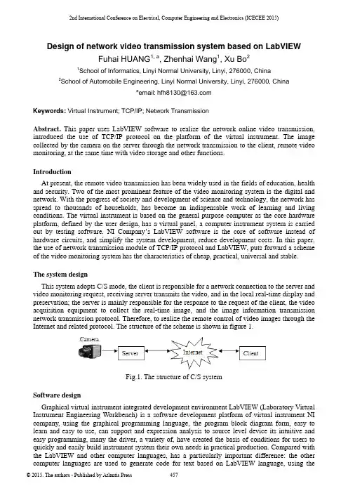
2nd International Conference on Electrical, Computer Engineering and Electronics (ICECEE 2015)Design of network video transmission system based on LabVIEWFuhai HUANG1, a, Zhenhai Wang1, Xu Bo21School of Informatics, Linyi Normal University, Linyi, 276000, China 2School of Automobile Engineering, Linyi Normal University, Linyi, 276000, Chinaa email:***************Keywords: Virtual Instrument; TCP/IP; Network TransmissionAbstract.This paper uses LabVIEW software to realize the network online video transmission, introduced the use of TCP/IP protocol on the platform of the virtual instrument. The image collected by the camera on the server through the network transmission to the client, remote video monitoring, at the same time with video storage and other functions.IntroductionAt present, the remote video transmission has been widely used in the fields of education, health and security. Two of the most prominent feature of the video monitoring system is the digital and network. With the progress of society and development of science and technology, the network has spread to thousands of households, has become an indispensable work of learning and living conditions. The virtual instrument is based on the general purpose computer as the core hardware platform, defined by the user design, has a virtual panel, a computer instrument system is carried out by testing software. NI Company’s LabVIEW software is the core of software instead of hardware circuits, and simplify the system development, reduce development costs. In this paper, the use of network transmission module of TCP/IP protocol and LabVIEW, puts forward a scheme of the video monitoring system has the characteristics of cheap, practical, universal and stable.The system designThis system adopts C/S mode, the client is responsible for a network connection to the server and video monitoring request, receiving server transmits the video, and in the local real-time display and preservation; the server is mainly responsible for the response to the request of the client, the video acquisition equipment to collect the real-time image, and the image information transmission network transmission protocol. Therefore, to realize the remote control of video images through the Internet and related protocol. The structure of the scheme is shown in figure 1.Fig.1. The structure of C/S systemSoftware designGraphical virtual instrument integrated development environment LabVIEW (Laboratory Virtual Instrument Engineering Workbench) is a software development platform of virtual instrument NI company, using the graphical programming language, the program block diagram form, easy to learn and easy to use, can support and expression analysis to source level device its intuitive and easy programming, many the driver, a variety of, have created the basis of conditions for users to quickly and easily build instrument system their own needs in practical production. Compared with the LabVIEW and other computer languages, has a particularly important difference: the other computer languages are used to generate code for text based on LabVIEW language, using thegraphical programming language.LabVIEW software provides a visual and motor module, this module can initialize camera and video image capture, as shown in figure 2(a).In addition the TCP protocol controls provide the data communication module, protocol, can be very convenient to establish a network connection and data transmission, as shown in figure 2(b).(a) NI-IMAQ module (b) TCP moduleFig.2. LabVIEW moduleThe system initialization of the camera on the server side, and connected through the TCP protocol to establish with the client, the client to receive and display the video image of the program flow diagram as shown in figure 3.Fig.3. System flow diagramServer designServer side call camera image acquisition. LabVIEW image acquisition is mainly composed of two kinds of methods, one is the use of industrial camera driver, such as LabVIEW driver, DLL dynamic link library; another is the use of NI IMAQ and IMAQdx driver for image acquisition. This design choice is driven by the use of NI for image acquisition IMAQdx. Video image shouldbe format conversion before transmission effectively. This design uses the TCP/IP protocol for the video transmission. TCP is a connection based protocol, the transmission must be created before the data transmission. To create a TCP connection, need to specify the address and port of the address. Different ports address different services on the site. Through the "TCP VI Listener" create a listener and wait for a specified port has been received in the TCP connection. If the connection is successful, VI will return a connection handle, connecting the remote TCP address and port of the client. With two 'TCP Write' VI to send data, the first node to transmit data length, the second nodes transmit video data. Finally, the end connected with the TCP Close Connection 'VI'. The server program block diagram shown in figure 4.Fig.4. The server program block diagramThe design of the clientThe client is mainly to complete the network connection, read the video data and save functions. 'TCP Open Connection' with VI open TCP, and then use the two 'TCP Read' VI to read the data, the first to receive video data as input length of second nodes, second nodes receive video data, finally, 'TCP Close Connection' by VI end connection. Block diagram as shown in figure 5.Fig.5. The client programTest resultFirst select a port before the program runs, usually more than 1000, because a lot of less than 1000 of the port is other procedures have been occupied port. Set the server and the client port must be consistent, in order to ensure the normal listening. When the client sends a request to the server in response to the request, the connection, the connection is established, the server will send data package, finally, the client receives the data, and the data unpack restore. The result of running the program is shown in figure 6.Fig.6. The result of running the programConclusionThis design adopts C/S mode, using LabVIEW platform provides a powerful network functions and network conditions, and combined with the TCP/IP protocol, the effective realization of video network transmission and preservation, by running results show the good performance. References[1]LabVIEW User Manual: USA: National Instruments Corporation (1998).[2]Changqing Cai, WeiJun Zhang: The design on the multi-temperature testing system based on the Laview, International Seminar on Future Biomedical Information Engineering (FBIE) (2008).[3]Using External Code in LabVIEW, National Instruments Corporation (2003).[4]Wagner. C, Armenta. S, Lendl. B: Talanta 80(3)(2010).[5]F. Correa Alegria, E. Martinho, F. Almeida: Measurement 42(7) (2009).。
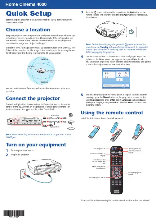
Quick SetupBefore using the projector, make sure you read the safety instructions in the online User’s Guide .Choose a locationKeep the projector level and place it at a height so its lens is even with the top or bottom of the screen and is centered horizontally. If this isn’t possible, use the lens shift feature or the keystone correction button on the projector to reposition the image (see “Adjust the image”).In order to view 3D images correctly, RF 3D glasses must be worn within 32 feet (10 m) of the projector. Use the image below to determine the viewing distancefor 3D projection (the shading represents the 3D viewing area):See the online User’s Guide for more information on where to place your projector.Connect the projectorConnect multiple video devices and use the Source buttons on the remote control or the button on the projector to switch between them. For additional connection types, see the online User’s Guide .Note: When connecting a source that requires HDCP 2.2, you must use the HDMI1 port.Turn on your equipment1 Turn on your video source.2Plug in the projector.3Press the power button on the projector or the On button on the remote control. The shutter opens and the power light flashes blue, then stays on.Note: To shut down the projector, press the power button on the projector or the Standby button on the remote control, then press the button again to confirm, if necessary. Wait for cooldown to complete before unplugging the projector.4Use the arrow buttons on the remote control to highlight any of the options on the Home screen that appears, then press Enter to select it. You can display a QR code, switch between projection sources, and quickly access various adjustment options from this screen.5The default language of the menu system is English. To select another language, press the Menu button on the projector or remote control. Select Extended and press Enter . Select Language and press Enter . Select your language and press Enter . Press the Menu button to exit the menu system.Using the remote controlInstall the batteries as shown (two AA batteries).Turn off projector displayNavigate projector menusTurn projector off For more information on using the remote control, see the online User’s Guide .Adjust the image1 P ress the Patternbutton on the remote control to display a test pattern.2 T o raise the image or correct a tilted image, adjust the front feet asshown below.3 P ress the4 P ress the56 I f your image looks like or , you can use the buttons on theprojector to correct this.Note: Using the keystone adjustment can affect the size and effectiveresolution of your image. If possible, change the position of yourprojector to eliminate the keystone effect and use the lens shift optionto position the image as necessary.7 Press Esc to exit.Viewing 3D imagesTo view 3D content, you must first connect a 3D-compatible video device toone of the HDMI ports on your projector. You also need a pair of Epson® (partnumber V12H548006) or Epson-compatible RF 3D active shutter glasses.1 Turn on and begin playback on the 3D-compatible video device.Note: Make sure you set the video device to play content in 3D mode.2 Slide the power switch on your 3D glasses to the On position.Note: If the glasses don’t automatically display 3D content, you may needto pair them with the projector. Move the glasses within 10 feet (3 m) of theprojector, then press and hold the Pairing button on the 3D glasses for atpress EnterMediumTroubleshootingIf you see a blank screen or the No signal message after turning on your video device or computer, check the following:•Make sure the power light on the projector is blue and not flashing.•P ress the button on the projector or one of the Source buttons on the remote control to switch to the correct image source, if necessary.•O n some Windows® laptops, you may need to hold down the Fn key and press F7 or the function key that lets you display on an external monitor.It may be labeled CRT/LCD or have an icon such as.•O n Windows 7 or later, hold down the Windows key and press P at the same time, then click Duplicate.•I f you’re using a Mac laptop, open System Preferences and select Displays. Click the Arrangement tab and select the Mirror Displayscheckbox.If 3D images aren’t displaying properly, check the following:•P ress the Menu button, then select Signal > 3D Setup > 3D Display and make sure that the 3D option is selected.•M ake sure that you are within the 3D viewing range. See “Choose a location” on the front of this sheet or the online User’s Guide for more information.•C heck that your 3D glasses have not entered standby mode. Slide the power switch on the 3D glasses to the Off position, then back to the On position.•C heck that your video device and media are both 3D-compatible. Refer to the documentation that came with your video device for moreinformation.Where to get helpManualsFor more information about using the projector, click the icons on your desktop to access the online manuals (requires an Internet connection). If you don’t see icon links to the manuals, you can install them from the projector CD or go to the Epson website, as described below.Telephone support servicesTo use the Epson® PrivateLine® Support service, call (800) 637-7661. This service is available for the duration of your warranty period. You may also speak with a support specialist by calling (562) 276-4394 (US) or (905) 709-3839 (Canada). Support hours are 6 am to 8 pm, Pacific Time, Monday through Friday, and7 am to 4 pm, Pacific Time, Saturday. Days and hours of support are subjectto change without notice. Toll or long distance charges may apply. Internet supportVisit /support (U.S.) or www.epson.ca/support (Canada) for solutions to common problems. You can download utilities and documentation, get FAQs and troubleshooting advice, or e-mail Epson. RegistrationRegister today to get product updates and exclusive offers. You can use the CD included with your projector or register online at /webreg.Optional accessoriesFor a list of optional accessories, see the online User’s Guide.You can purchase RF 3D glasses (part number V12H548006) or other accessories from an Epson authorized reseller. To find the nearest reseller, call 800-GO-EPSON (800-463-7766). Or you can purchase online at (U.S. sales) or www.epson.ca (Canadian sales).NoticesBluetooth Safety and SpecificationsContains Bluetooth module model: DBUB-E207This document provides safety instructions and describes the specifications. Read this document carefully before use to ensure your safety and product performance.U.S.Contains FCC ID: BKMAE-E207This device complies with Part 15 of the FCC Rules. Operation is subject to the following two conditions: (1) This device may not cause harmful interference, and (2) this device must accept any interference received, including interference that may cause undesired operation.This equipment has been tested and found to comply with the limits for a Class B digital device, pursuant to Part 15 of the FCC Rules. These limits are designed to provide reasonable protection against harmful interference in a residential installation. This equipment generates, uses and can radiate radio frequency energy and, if not installed and used in accordance with the instructions, may cause harmful interference to radio communications. However, there is no guarantee that interference will not occur ina particular installation. If this equipment does cause harmful interference to radioor television reception, which can be determined by turning the equipment off and on, the user is encouraged to try to correct the interference by one of the following measures:•Reorient or relocate the receiving antenna.•Increase the separation between the equipment and receiver.•C onnect the equipment into an outlet on a circuit different from that to which the receiver is connected.•Consult the dealer or an experienced radio/TV technician for help.This transmitter must not be co-located or operating in conjunction with any other antenna or transmitter.Radiation Exposure Statement:This equipment complies with FCC radiation exposure limits set forth for an uncontrolled environment. This equipment should be installed and operated with minimum distance 7.9 inches (20 cm) between the radiator and your body.CanadaContains IC: 1052D-E207This Class B digital apparatus complies with RSS-102 of the IC radio frequency (RF) Exposure rules.This device complies with Industry Canada license-exempt RSS standards. Operationis subject to the following two conditions: (1) This device may not cause harmful interference, and (2) this device must accept any interference received, including interference that may cause undesired operation.This transmitter must not be co-located or operating in conjunction with any other antenna or transmitter.CAN ICES-3(B) / NMB-3(B)Radiation Exposure Statement:This equipment complies with IC RSS-102 radiation exposure limits set forth for an uncontrolled environment. This equipment should be installed and operated with minimum distance 20 cm (7.9 inches) between the radiator and your body. Declaration of ConformityAccording to 47CFR, Part 2 and 15, Class B Personal Computers and Peripherals; and/or CPU Boards and Power Supplies used with Class B Personal Computers.We: Epson America, Inc.Located at: 3840 Kilroy Airport WayMS: 3-13Long Beach, CA 90806Telephone: (562) 981-3840Declare under sole responsibility that the product identified herein, complies with47CFR Part 2 and 15 of the FCC rules as a Class B digital device. Each product marketed, is identical to the representative unit tested and found to be compliant with the standards. Records maintained continue to reflect the equipment being producedcan be expected to be within the variation accepted, due to quantity production and testing on a statistical basis as required by 47CFR 2.909. Operation is subject to the following two conditions: (1) this device may not cause harmful interference, and (2) this device must accept any interference received, including interference that may cause undesired operation.Trade Name: EpsonType of Product: LCD ProjectorModel: H715AMarketing Name: Home Cinema 4000Epson America, Inc. Limited WarrantyTwo-Year Projector Limited Warranty and 90-Day Lamp Limited WarrantyWhat Is Covered: Epson America, Inc. (“Epson”) warrants to the original retail purchaser of the Epson projector product enclosed with this limited warranty statement that the product, if purchased new and operated in the United States, Canada, or Puerto Rico will be free from defects in workmanship and materials for a period of two years from the date of original purchase. This limited warranty applies only to the projector and not to the projector lamp, which carries a limited warranty period of ninety days from the date of original purchase. For warranty service, you may be required to provide proof of the date of original purchase.What Epson Will Do To Correct Problems: If your product requires service during thelimited warranty period, please call Epson at the number on the bottom of this statement and be prepared to provide the model, serial number, and, if required, date of original purchase. If Epson confirms that warranty service is required, Epson will, at its option, repair or replace the defective unit, without charge for parts or labor. If Epson authorizes an exchange for the defective unit, Epson will ship a replacement product to you, freight prepaid, so long as you use an address in the United States, Canada, or Puerto Rico. You are responsible for securely packaging the defective unit and returning it to Epson within five working days of receipt of the replacement. Epson requires a debit or a credit card number to secure the cost of the replacement product in the event that you fail to return the defective one. If Epson authorizes repair instead of exchange, Epson will direct you to send your product to Epson or its authorized service center, where the product will be repaired and sent back to you. You are responsible for packing the product and for all postage or shipping costs to and from the Epson authorized service center. When warranty service involves the exchange of the product or of a part, the item replaced becomes Epson property. The exchanged product or part may be new or refurbished to the Epson standard of quality. If service cannot be provided on the product for any reason and Epson no longer sells the same model, Epson will replace your product with a model of equal or superior value. Replacement products or parts assume the remaining warranty period of the original product. If Epson replaces the lamp as part of thewarranty service, the replacement lamp carries the limited 90-day warranty stated above.What This Warranty Does Not Cover: This warranty covers only normal use in the United States, Canada, or Puerto Rico.This warranty does not cover the following:•Excessive continual use •Consumables such as filters •Installation or removal•Cosmetic damage caused by handling or normal wear and tear during usage• D amage caused by failure to properly maintain the projector (see your online User’sGuide for details) • D amage caused by interaction with non-Epson products, such as add-in cards or cables• A ny problem resulting from misuse, abuse, improper installation, neglect, impropershipping, disasters such as fire, flood, and lightning, improper electrical current, software problems, exposure to chemical smoke, or excessive humidity • A ny problem resulting from service by other than Epson or an Epson AuthorizedServicerEpson is not responsible for warranty service should the Epson label or logo or the rating label or serial number be removed. This warranty is not transferrable. Epson is not responsible for your data or applications, which cannot be restored and should be backed up by you. Postage, insurance, or shipping costs incurred in presenting your Epson product for carry-in warranty service are your responsibility. If a claimed defect cannot be identified or reproduced in service, you will be held responsible for costs incurred.DISCLAIMER OF OTHER WARRANTIES: THE WARRANTY AND REMEDY PROVIDEDABOVE ARE EXCLUSIVE AND IN LIEU OF ALL OTHER EXPRESS OR IMPLIED WARRANTIES INCLUDING, BUT NOT LIMITED TO, THE IMPLIED WARRANTIES OF MERCHANTABILITY , NONINFRINGEMENT OR FITNESS FOR A PARTICULAR PURPOSE. SOME LAWS DO NOT ALLOW THE EXCLUSION OF IMPLIED WARRANTIES. IF THESE LAWS APPLY , THEN ALL EXPRESS AND IMPLIED WARRANTIES ARE LIMITED TO THE WARRANTY PERIOD IDENTIFIED ABOVE. UNLESS STATED HEREIN, ANY STATEMENTS OR REPRESENTATIONS MADE BY ANY OTHER PERSON OR FIRM ARE VOID.EXCLUSION OF DAMAGES; EPSON’S MAXIMUM LIABILITY: IN NO EVENT SHALL EPSON OR ITS AFFILIATES BE LIABLE FOR ANY SPECIAL, INCIDENTAL, OR CONSEQUENTIAL DAMAGES OR ANY LOST PROFITS RESULTING FROM THE USE OR INABILITY TO USE THE EPSON PRODUCT, WHETHER RESULTING FROM BREACH OF WARRANTY OR ANY OTHER LEGAL THEORY . IN NO EVENT SHALL EPSON OR ITS AFFILIATES BE LIABLE FOR DAMAGES OF ANY KIND IN EXCESS OF THE ORIGINAL RETAIL PURCHASE PRICE OF THE PRODUCT.Arbitration, Governing Laws: Any dispute, claim or controversy arising out of or relating to this warranty shall be determined by arbitration in Los Angeles County, California before a single arbitrator. The arbitration shall be administered by JAMS pursuant to its Comprehensive Arbitration Rules and Procedures. Judgment on the award may beentered in any court having jurisdiction. Any action must be brought within three months of the expiration of the warranty. This clause shall not preclude parties from seeking provisional remedies in aid of arbitration from a court of appropriate jurisdiction. This warranty shall be construed in accordance with the laws of the State of California, except this arbitration clause which shall be construed in accordance with the Federal Arbitration Act.Other Rights You May Have: This warranty gives you specific legal rights, and you may also have other rights which vary from jurisdiction to jurisdiction. Some jurisdictions do not allow limitations on how long an implied warranty lasts, or allow the exclusion or limitation of incidental or consequential damages, so the above limitations or exclusions may not apply to you.In Canada, warranties include both warranties and conditions.EPSON is a registered trademark, and EPSON Exceed Your Vision is a registered logomark of Seiko Epson Corpo-ration. Epson Connection is a service mark and PrivateLine is a registered trademark of Epson America, Inc.Mac is a trademark of Apple Inc., registered in the US and other countries.General Notice: Other product names used herein are for identification purposes only and may be trademarks of their respective owners. Epson disclaims any and all rights in those marks.This information is subject to change without notice.© 2017 Epson America, Inc., 3/17Printed in XXXXXXCPD-53682To find the Epson Authorized Reseller nearest you, please visit: in the U.S. or www.epson.ca in Canada.To find the Epson Customer Care Center nearest you, please visit/support in the U.S. or www.epson.ca/support in Canada.To contact the Epson Connection SM , please call (800) 637-7661 or (562) 276-4394 in the U.S. and (905) 709-3839 in Canada or write to Epson America, Inc., P .O. Box 93012, Long Beach, CA 90809-3012.。
International Conference on Advances in Materials, Machinery, Electrical Engineering (AMMEE 2017)Transmission of UAV videos based On HEVCZhiyuan Li, Chao Wang, Xiaoduo ZhangZhengzhou Electromechanical Engineering Research Institute, China****************Keywords:UAV, transmission of videos, region-of-interest, HEVC.Abstract. To meet the requirement of high-quality transmission of videos captured by unmannedaerial vehicles (UAV) with low bandwidth, a novel rate control (RC) scheme based on region-of-interest (ROI) is proposed. First, the ROI information is sent to the encoder with the latest highefficient video coding (HEVC) standard to generate an ROI map. Then, by using the ROI map, bitallocation methods are developed at frame level and large coding unit (LCU) level, to avoid inaccurate bit allocation produced by camera movement. At last, by using a better robustness R-λ model, the quantization parameter (QP) for each LCU is calculated. The experimental results show that theproposed RC method can get a lower bit rate error and a higher quality for reconstructed video bychoosing appropriate pixel weight on the HEVC platform1.IntroductionUnmanned aerial vehicles (UAVs) equipped with surveillance systems have been widely used inmilitary missions and civilian domains[1,2]. The huge data has posed big challenges for the videocompression systems on the UAVs. Rate control (RC) plays a major role in video coding. By usingRC, better video quality can be achieved without violating the constraints imposed by the availablechannel bandwidth or memory requirement. Many valuable results about RC algorithms based onregion-of-interest (ROI) have been published[3-6]. The methods in Refs.[3]—[6] are developed fordifferent preceding compression standards, which are not suitable for the latest high efficiency videocoding (HEVC) standard with the flexible picture partition and some other techniques[7-9]. Moreover,they are designed for low- resolution videos,which are not suitable for high-resolution and high-frame-rate video services, such as UAV videos.Although some RC methods[10,11] are proposed for HEVC at high resolutions, these methods computethe quantization parameter (QP) with a quadratic model, which may degrade the video quality due tothe inaccurate bit allocation, and has been replaced by the R-λ model with better robustness for HEVC[12,13]. ROI based RC approaches with R-λ model[14,15] have already been applied in the video conferencing application. However, objects’ diversity anduncertainty of an aerial video in various missions make ROI detection more difficult than the singletype ROI in video conferencing. Furthermore, the ratio of bit allocation between every picture in onegroup of picture (GOP) is inflexible and predetermined in the previous schemes, which cannot meetthe videos captured by high speed UAVs.2.The Framework of The ROIIn this paper, we design a novel RC scheme which is appropriate for the high-resolution and high-frame-rate UAV video coding in HEVC. It uses ROI map for bit allocation at frame level and largecoding unit (LCU) level. The scheme allocates more bits to the frames with a larger ROI at framelevel. In this way, the larger ROI can get enough coding bits to improve the quality of ROI. At LCUlevel, different numbers of bits are dynamically allocated to LCUs with the ROI map. It can avoid inaccurate bit allocation from local object motions or global camera motions. Then the QP for each LCU is calculated with the R-λmodel. Experimental results show that in HEVC, the proposed ROI based RC scheme can significantly improve the performance compared with state-of-art methods.Fig.1 presents the overview of the proposed scheme. Firstly, the scheme generates an ROI map by using the objects detected in UAV videos. There are two classes of methods can be utilized to realize object detection. One is automatic detection based on computer vision, and the other is manual detection based on interactive information. After that, the RC module can make use of the generated ROI map to perform two efficient bit allocation methods at frame level and LCU level. Then R- model is applied to calculate the QP.Fig. 1 The framework of the ROI based rate controlThe previous ROI based RC schemes are designed for the conversational applications, in which ROI detections are mostly implemented for face detection or motion detection. The object detection method for specific application limits the applied scope and makes the detected ROI fairly inaccurate for non-conversational scenarios. Different from the single type object in conversation, many regions may be the ROI (such as pedestrian, road and vehicles) in an aerial video. The diversity and uncertainty of objects in various missions has posed big challenges to the ROI detection in the UAV videos.Fortunately, many valuable results about salient objects detection methods have been published.A comprehensive survey of salient object detection can be found in Ref. [16]. Cheng et al [17] designed a good generic objectness measure method with high object detection rate. Moreover, the development of the researches on target detection for UAV in different applications [18] brings convenience to multi-objective extraction for UAV videos. On the other hand, the interaction and the real-time performance are the two key characteristics for the UAV system. Targets can be detected with simple interaction with users or other equipment’s in the UAV system. The encoder obtains ROI with high quality by the manual detection to avoid a large amount of calculation and inaccuracy. After detecting ROI in one frame, pixels in ROI are assigned with weight value k, and pixels in non-ROI are assigned with a weight value 1, which can be expressed as(1)where RM is the ROI map at pixel level having the same size with the original frame, and (w, h) is the location of the pixel in the frame. Then, the ROI map is sent to HEVC encoder to guide an ROI based RC with an effective bit allocation method.Since a human observer is the end-user of UAV video, enhancing the quality of ROI is an important task to improve the user satisfaction. As the overall coding and transmission resources are limited, allocating more bits on ROI while decreasing the quality of non-ROI is reasonable. Thus, the necessary bit stream can be reduced by allocating fewer bits for the less important parts. We introduce the proposed ROI based RC scheme with HEVC encoder for UAV videos. Bit allocation methods are applied in this scheme. At frame level bit allocation,We allocate bits to each frame in the GOP according to the frame weight measured by the ROI map at frame level. Similarly, RC scheme allocates bits to each LCU in the frame in accordance with their importance measured by the ROI map at LCU level.In the traditional R-λ method [12], the ratio of bit allocation between each picture in one GOP is determined by bit per pixel (BPP). Obviously, BPP value ignores the characteristics of video content, since it only depends on the bandwidth, frame rate and resolution. Hence, the BPP value used as a weight performs poorly at frame level bit allocation. Then, the problem of frame level bit allocation can be solved by the ratio between the Varangian multiplier (λ) values which are derived from R-λmethod [13].However, the ratio of λ within each GOP is fixed. It cannot adapt to the changeful aerial video well, especially when the UAV flies rapidly or works in zoom state. When working in short-focus mode for the target positioning, the ROI size is smaller. We can reduce the allocation bits to improve the compression ratio. On the contrary, when working in long-focus mode to identify and observe target details, the ROI size is larger. We should increase the allocation bits to improve the satisfaction of observer. Therefore, in order to meet the requirement of the UAV application, the frame level bit allocation problem can be solved by the ratio between the ROI maps at frame level in a GOP. The ROI map at frame level Fω[i] can be expressed as(2)where Fω[i] represents the bit allocation weight of the ith frame in the current GOP, H and W are the height and width of one frame, and N ROI[i] is the number of pixels in the ROI of the current frame. Then RC scheme allocates bits adaptively for each frame in the GOP according to their importance measured by Fω[i]. More bits are allocated to more important frames to improve the quality of video. Fewer bits are allocated to less important to improve the compression ratio. Then, the target bits for the ith frame in the current GOP can be achieved by(3)where T f [i] is the target bits to be allocated for the ith frame in the current GOP, T GOP,rem is the remaining bits used to encode the rest of frames in the current GOP, and Fωrem is the sum of weight for the rest frames in the current GOP.Mean absolute difference (MAD) of the LCU at the same position in the previously decoded frame is used as a weight at LCU level bit allocation in the typical RC algorithm [12]. However, MAD of the previous LCU may be quite different from the MAD of the current one with the high speed movement of UAV. Thus the MAD performs poorly at LCU level bit allocation. Gradient of the current LCU was used to allocate the bit at LCU level in Ref. [19], as it can be obtained directly from the current LCU. Instead of the gradient weight, we use ROI information of the current LCU to allocate bits at LCU level. The quality of ROI can be controlled flexibly by adjusting the pixel weight in the ROIs. The ROI map at LCU level Lω[i, j] can be expressed as(4)where Lω[i, j] represents the bit allocation weight of the jth LCU in the ith frame, H[j] and W[j] are the height and width of the jth LCU, r j and c j are row and column position of the top left corner of the jth LCU in ith frame, and N ROI[i, j] is the number of pixels in the ROI of the jth LCU. The LCU with larger ROI means that it is more important and it needs more protections during video transmission.Once the target bits for the ith frame are allocated, the target bits for LCU denoted by T LCU[i, j] can be achieved with the ROI map at LCU level as(5)where Lωrem is the weight of the rest LCU in the current frame, and T f,rem is the remaining bits used to encode the rest of LCUs in the current frame. Clearly, the quality of ROI can be emphasized, since more target bits are allocated through Eq.(5) with high values of Lω[i, j] in ROI. We can flexibly control the quality of ROI by adjusting the value of k in Eq.(1). In this way, more bits are allocated to ROI for ensuring better perceived quality. λ can be derived from T LCU[i, j] by R-λmodel as(6)Where αand βare initialized as 3.2003 and −1.367, respectively, and then updated by least square regression once a coded picture is available. Fromλ, QP is finally obtained by(7)3.Experimental ResultsFig. 2 shows the RD curves of HM16.0 and our algorithm in ROI, non-ROI and whole regions. It is observed that our approach outperforms HM 16.0 at various bitrates in terms of average Y-PSNR of the ROI. As for the cost, the RD performance of non-ROI may be degraded. However, thanks to the human vision system (HVS), people pay more attention to ROI, and the reduction of visual quality outside ROI is almost unnoticeable. Consequently, the degraded RD performance of non-ROI has few negative effects on the perceived visual quality of the entire frame.Fig. 2 RD performance comparison between the HM16.0 and our algorithm in ROI, non-ROI andwhole regionsFig. 3 demonstrates the reconstructed frame of the UAV video sequence compressed at 1 000 kbit/s obtained by HM16.0 and our algorithm. As expected, our approach can yield more favorable visual quality in the whole frame, since the visual quality in the ROI is improved and that in non-ROI is reduced almost unnoticeably, which can be seen in the amplified block in Fig.3.Fig. 3 Perceived visual quality comparison of encodedframe and amplified blocks between (a) HM16.0 and (b)our algorithmAt last, we compare the results of our scheme with different k and the gradient based R- (GRL) method[19] in the aspect of PSNR increase (ΔPSNR) on HM16.0 in ROI. As shown in Fig.4, the larger k leads to the bigger increase of PSNR in ROI. This means that our scheme can flexibly control the quality of ROI by adjusting the k value.Fig. 4 ΔPSNR in ROI of our algorithm with different k= 9 and 5 and GRL method4.ConclusionIn this paper, we put forward an ROI based RC scheme in HEVC standard. The scheme is developed for UAV applications. A more efficient and accurate ROI information can be obtained for real-time encoder through the salient object detection method and the interaction of UAV. More bits are assigned to the frame which contains larger ROI to adapt with the fast changing scene as the UAV flies at high speed. Bits are adaptively allocated with the ROI map at LCU level in order to improve the quality of the ROI. The quality of ROI can be flexibly controlled by using appropriate pixel weight in the ROI, and the R- model with a better robustness is used to get a proper QP. The experimental results demonstrate that the reconstructed video quality is improved, and the bitrate error is reduced. Hence, the proposed RC scheme has potential value to be applied in UAV applications.References[1].R. Schneider man, IEEE Signal Processing Magazine 29, 8 (2012).[2].M. Bhaskaranand and J. D. Gibson, IEEE Journal of Selected Topics in Signal Processing 9, 139(2015).[3].B.-R. Joan, S.-S. Joan and A.-L. Francesc, IEEE Signal Processing Letters 16, 45 (2009).[4].J. Y. Kim, C. H. Yi and T. Y. Kim, IEEE Transactions on Consumer Electronics 56, 951 (2010).[5].Y. Liu, Z. Li and Y. Soh, IEEE Transactions on Circuits and Systems for Video Technology 18,134 (2008).[6].K. Sun and D. Wu, Journal of Visual Communication & Image Representation 30, 234 (2015).[7].Xu Sheng-yang, Yu Mei, Jiang Gang-yi, Fang Shu-qing and Shao Feng, Journal ofOptoelectronics·Laser 26, 2381 (2015).[8].Xu Jian, Wang Rang-ding, Huang Mei-ling, Li Qian and Xu Da-wen, Journal ofOptoelectronics·Laser 26, 1753 (2015). (in Chinese)[9].G. J. Sullivan, J.-R. Ohm, W.-J. Han and T. Wiegand, IEEE Transactions on Circuits and Systemsfor Video Technology 22, 1649 (2012).[10].M. Xv, X. Deng, S. Li and Z. Wang, IEEE Journal of Selected Topics in Signal Processing 8,475 (2014).[11]. M. Simone, B. Riccardo and R. Roberto, A Saliency-Based Rate Control for People Detectionin Video,[12].IEEE International Conference on Acoustics, Speech and Signal Processing, 2016 (2013).[13]. B. Li, H. Li, L. Li and J. Zhang, Rate Control by R-lambda Model for HEVC, ITU-T SG16Contribution, JCT-VC K0103, Shanghai, (2012).[14].X. Wang and M. Karczewicz, Intra Frame Rate Control Based on SATD, ITU-T SG16Contribution, JCT-VC M0257, Incheon, (2013).[15].S. Li, M. Xu, X. Deng and Z. Wang, Signal Processing-Image Communication 38, 127 (2015).[16].M. Marwa, C. Marco and P.-P Beatrice, Region-of-Interest Based Rate Control Scheme forHigh Efficiency Video Coding, IEEE International Conference on Acoustics, Speech and Signal Processing, 7338 (2014).。
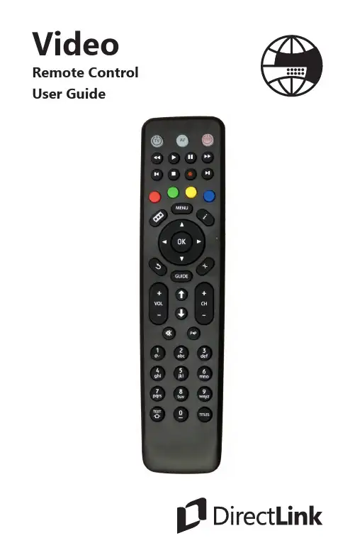
VideoRemote Control User Guide2Remote Control LayoutSTB POWER Turn set top box device on or off Playback Controls Control playback ofDVR or Live TVRECBegin DVR recordingINFODisplay the InfobarOKEnter a choice youhave madeEXITExit to Main ScreenGUIDEDisplay TV GuideCH +/-Change the channelUp/Down Arrows Page Up and PageDown ControlP<PReturn to previouschannel TITLESActivate SubtitlesWillow Remote ControlThis is not a universal remote control that can be used to program or control the menu or tool functions of your television set. We suggest the use of t he remote control that came with your TV set for this type of program functionality or to use a universal remote that works with Amino set top boxes. For the complete Amino remote control user guide visit our website at: https://www.directlink.coop/docs/AminoRemoteControlUserGuidev4.pdfTV PowerTurn TV on or off TV AV Source Change TV Input StopStop playback of DVR content InfoDisplay the Infobar LIST MENUDisplays DVR Guide MENUDisplays Menubar ARROWSNavigation Arrows Not Active For future use VOL + / -Adjust volumeMUTEToggle TV audio on or offNumber Pad Enter a channel number or PIN Remote Setup3OperationWhen the remote control is first operated all buttons transmit commands for the set-top box. Point the remote control towards the front of the set-top box when pressing a remote control button to ensure correct operation. Do not cover the IR window at the front of the product.When a button on the remote is pressed either the set-top box standby button will flash (or TV standby button if a TV brand has been entered) depending on which product is being controlled by the remote control.If a button is pressed for more than 30 seconds the remote control will stop transmitting commands in order to preserve battery life.TV control setup: Brand SearchThe remote control can also be programmed to operate certain functions of your TV set. To program this functionality then perform the following instructions in sequence. In case of a mistake, the process can be exited at any point by pressing and holding the Text/ SHIFT button and then at the same time pressing the STOP button. The remote control will revert to normal operation and no TV brand code will be stored.1 Determine the manufacturer of your TV set2 Look up the 4-digit manufacturer code supplied in thismanual and make a note of this code3 Make sure your TV set is turned on. (The set-top box does notneed to be turned on to perform this programing feature)4 Press and hold both the 1 and the 3 buttons at the sametime on the remote control for approximately 3 secondsuntil the TV standby button remains lit, then release bothbuttons45 Now enter the 4 digit manufacturer code for your TV set. Oneach digit entry the TV standby button will flash. On entry ofthe 4th digit the TV standby button will flash then remain lit6 Point the remote control at the TV set and press and holddown the TV Standby Button or the Mute button on theremote control7 When the TV either turns off or brings up the MUTE symbolon screen, then release that button. This may take a fewminutes to happen8 Press and hold the Text/SHIFT button and then at thesame time press the STOP button to finish setting up the TVcontrol mode.The TV standby button will go out. The TV control function is now programmed into the remote control.The following buttons should now operate the TV set: TV Standby, AV source select, Volume Up, Volume Down, MuteIf not all the above mentioned buttons operate the TV set then a KEY FIX operation can be performed. (See page 6).Should the TV model be changed and the remote control requires re-programming then repeat the above setup procedure with the new TV.Should the TV brand be not successfully found by the remote control then the TV standby button will flash rapidly and the remote control will revert to normal operation. No TV brand code will be stored.5 TV control setup: Auto SearchShould the TV brand not be successfully found by the previous Brand Search method then Auto Search can be used.Caution: this process may take a long time to find your TV code (in cases up to 5 minutes)Make sure your TV set is turned on. (The set-top box does not need to be turned on to perform this programing feature)1 Press and hold both the 1 and the 3 buttons at the same timeon the remote control for approximately 3 seconds until the TVstandby button remains lit, then release both buttons2 Point the remote control at the TV set and press and hold downthe TV Standby Button or the Mute button on the remotecontrol3 When the TV either turns off or brings up the MUTE symbol onscreen, then release that button. This may take up to 5 minutesto happen4 Press and hold the Text/SHIFT button and then at the same timepress the STOP button to finish setting up the TV control mode.5 The TV standby button will go out. The TV control function is nowprogrammed into the remote control.Should the TV brand be not successfully found by the remote control then the TV standby button will flash rapidly and the remote control will revert to normal operation. No TV brand code will be stored.If even Auto Search fails to successfully setup operation of the TV set, then the remote is unable to control that particular TV set.6TV Shift functionalityWhen a TV brand has successfully been programmed into the remote control with the above steps, the following additional buttons may also control the TV set. These can be accessed by pressing and holding the TEXT/SHIFT button 20 on the remote control and at the same time pressing:Digit buttons 0..9, Left, Right, Up, Down, OK, Channel Up, Channel Down, the 4 colour keysOperation of these buttons is not guaranteed to control the normally expected functionality of the TV set.Key FixIf not all the previously mentioned buttons operate the TV set then a KEY FIX operation can be performed as follows.1 Press and hold the 1and 9buttons simultaneously forapproximately 3 seconds until the TV standby button is lit2 Try all the above mentioned TV buttons3 If the TV does not respond to a button, then hold that button downpermanently. The remote control will now step through alternativesettings. When the TV responds correctly then release that button4 Repeat that procedure for other buttons if necessary5 Once finished, press TEXT/SHIFT and STOP at the same time.Removing TV functionalityTo reset the remote control and erase the TV functionality1 Press and hold the 1and 6buttons simultaneously forapproximately 3 seconds until the TV standby button is lit2 Enter the following key sequence in the correct order 9 9 63 The TV settings will be deleted from the remote control.7A.R. Systems0012 Abex0014 ABS0016 Accent0019 Acer0028 Acme3521 Acoustic Solutions0032 Action0033 Acura0036 ADA0038 ADC0040 Addison0043 Admiral0046 Advent0054 Adventura0055 Adyson0058 AEG0059 Aftron3470 Agashi0063 Agazi3522 AGB0064 Aiko0069 Aim0070 Aiwa0072 Akai0074 Akashi0075 Akiba0078 Akira0079 Akito0082 Akura0083 Alaron0085 Alba0086 Albatron0087 Alcyon0093Alienware0099Alkos3523Allorgan0105Allstar0108AmericaAction0123Amoi0132Amplivision0138Ampro0139Amstrad0140Anam0146AnamNational0147Andersson0148Anglo0151Anitech0154Ansonic0156AOC0165Aomni3555ApexDigital0170Apollo0171Apple0172Arc En Ciel0178Arcam0179ArcamDelta3524Ardem0184Arena3375Aristona0192ART0199ArthurMartin0200ASA0202Asberg0205Astar0218Astra0221Asuka0227ATD0229Atlantic0233Atori0237Auchan0240Audiosonic0264Audioton0266Audiovox0268Audioworld0269Ausind0276Autovox0280Aventura0287Awa0296Axxon0303Ayomi3525Baird0311Bang &Olufsen0314Barco0319BARON3959Basic Line0325Bastide0327Baur0331Baysonic0333Bazin0335Beaumark0340Beijing0345Beko0346Belcor0348Bell &Howell0350Belson0355Belstar0357BenQ0359Beon0361Berthen0363Best0364Bestar0368Bestar-Daewoo0369BGH3507Binatone0378BlackDiamond0384Black Star0386Blacktron3526Blackway0388Blaupunkt0390Blue Sky0395Blue Star0396Boca0399Bondstec0403Boots0405Bork3615BPL0413Bradford0414Brandt0416Brillian0422Brinkmann0423Brionvega0424Britannia0425Brockwood0430Broksonic0432Bruns0435BskyB0436BSR0437BTC0439Bush0445Caihong0462Caishi0465Cameron4032Brand Code Brand Code Brand Code Brand Code8Camper3911 Candle0480 Capsonic0486 Carad0488 Carena0489 Carnivale0491 Carrefour0492 Carver0494 Cascade0496 Casio0499 Catha4094 Cathay0501 CCE0504 Celebrity0509 Celera0510 Celestial0511 Centrex0516 Centrum0519 Centurion0520 Century0521 CGE0523 Changcheng0526 Changfei0527 Changfeng0528 Changhai0529 Changhong0530 Chimei3563 Chuangjia4096 Chun Yun0545 Chunfeng0546 Chung Hsin0547 Chunsun0549 Cimline0552 Cinex0563 Citizen0567 City0569Clarion0575Clarivox0576Clatronic0581Clayton0582CMS0590CMSHightec0591Coby0597Commer-cial Solu-tions0615Concerto0625Concorde0626Condor0627Conia0628Conrowa0634Contec0635ContinentalEdison0637Cosmel0647Craig0650Crosley0655Crown0658CS Elec-tronics0663CTC0664C-Tech0449CTX0665Curtis0666CurtisMathes0667CXC0670Cyber-Power0674Cybertron0675Cytron0680Daewoo0692Dainichi0694Dansai0699Dantax0702Datron4201Datsura0703Dawa0707Daytron0710De Graaf0716DEC0717Decca0718Deitron0722Dell0725Denon0731Denver0733Desmet0738Diamant0746Diamond0747DiamondVision0748Dick SmithElectronics0750Digatron0751Digihome0758Digiline0759DigiMax3808Digital Life0772DigitalLifestyles3567Digitex0780Digitor0781DirecTV0794Dixi0807Domeos0817Dongda0820Donghai0821Drean0832DSE0833DTS0837Dual0838Dual-Tec3528Dumont0840Duongjie4101Durabrand0842Dux0843D-Vision0684DVX0847Dwin0848DX An-tenna0849Dynatron0855Dynex3476Easy Living0860Ecco0864ECE0865Elbe0880Elbe-Sharp3529Elcit0883Electa3530ELECTROTECH3531Electro-band0888Electro-graph0889Electro-home0890Elektra0896Element3477Elfunk0899ELG0900Elin0902Elite0903Elman0907Elta0910Emerson0917Brand Code Brand Code Brand Code Brand Code9Emperor0921 Emprex0922 Envision0933 Enzer0934 Epson0937 Erres0942 ESA0943 ESC0945 Etron0949 Eurofeel0954 EuroLine0955 Euroman0956 Europa0957 Europhon0959 Evesham0972 Evolution0973 Excello0975 Expert0976 Exquisit0978 Fagor Life4102 Feilang0990 Feilu0991 Feiyue0993 Fenmenti4103 Fenner0994 Ferguson0996 Fidelity0998 Filsai1000 Finlandia1003 Finlux1004 Firstline1008 Fisher1009 Flint1014 FNR1016 Formenti1023Formenti-Phoenix1024Fortress1027Fraba1030Friac1040Frontech1042Fujitsu1052FujitsuGeneral1053FujitsuSiemens1054Funai1056Furichi1058Futronic1061Futuretech1064Gaba4059Galaxi1068Gateway1076GBC1078GE1081GeantCasino1082GEC1083Geloso1087GeneralTechnic1095Genesis1096Genexxa1097GFM3820G-Hanz3397Giant1113Gibralter1114Go Video1126Goldfunk1135GoldHand1136Goldline1138GoldStar1140Goodmans1142Gorenje1144GP1147GPM1149GPX1150Gradiente1151Graetz1152Granada1154Grandin1156Great Wall4105Gronic1160Grundig1162Grunkel1164Grunpy1165GVA3510Haaz1172Haier1175Haihong1176Halifax1179Hallmark1180Hampton1183Hankook1188Hanns.G3478Hannspree1189Hanseatic1190Hantarex1192Hantor1193HarleyDavidson1197Harman/Kardon1198Harvard1202Harwa1203Harwood1204Hauppauge1206Havermy1208HCM1210Helios1219Hello Kitty1221Hema1222Hemmer-mann1223HewlettPackard1229Hifivox1233Higashi1234Highline1236Hikona1237HiLine3533Hinari1243Hisawa1247Hisense1249Hitachi1251HitachiFujian1252Hitec1253Hitsu1257Hoeher1262Hongmei1272Hornyphon1277Hoshai1278HowardComputers1281HP1283Huafa1287Huanghai-mei1288Huanghe1289Huanglong1290Huangshan1291Huanyu1292Huari1294Huijiaban4108Brand Code Brand Code Brand Code Brand Code10Humax1298 Hush1304 Hygashi1308 Hyper1309 Hypson1312 Hyundai1315 Iberia1320 iBUYPOW-ER1322 ICE1324 ICeS1325 iDEAL3641 I-Inc3462 iLo1341 Imperial1346 Indesit1349 Indiana1350 Infinity1352 InFocus1353 Ingelen1354 Ingersol1355 Initial1356 Inno Hit1358 Innova1359 Innovation1360 Inotech1364 Insignia1368 Inspira4296 Inteq1373 Interactive3534 Interbuy1376 Interfunk1377 Internal1379 Interna-tional1380 Intervision1386IR4110Irradio1396IRT1397Isukai1402ITC1404ITS1405ITT1406ITT Nokia1407ITV1408Janeil1414JBL1420JCB1421Jean1424JEC1426Jensen1429Jiahua1435Jinfeng1438Jinhai1439Jinxing1442JMB1445JNC1446Jocel1448JTV3645Jubilee1460JVC1464Kaisui1471Kamosonic3535Kamp1475Kangchong1476Kanghua1477Kangwei4115Kapsch1483Karcher1484Kathrein1486Kawa1487Kawasho1489KDS1494KEC1496Ken Brown1499Kendo1500Kennedy1504Kennex1505Kenstar3756Kenwood1507Khind1511KIC1512Kingsley1520Kiota1522Kioto1523Kiton1525KLH1529KLL1531Kloss1532Kneissel1535Kolin1541Kolster1543Konig1547Konka1548Korpel1552Korting1554Kosmos1557Koyoda1561KTV1572Kunlun1578Kuro1579Kyoshu1583Kyoto1585L&SElectronic1588LaSAT1597Lavis1602Layco4117Lecson1606Lenco1615Lenoir1617Lesa1622Lexsor1626Leyco1627LG1628LG/Gold-star3536Liesenk3537Liesenk &Tter1630Liesenkot-ter1631Life3538Lifetec1633Linksys1640Lloyd’s1648Local IndiaTV1653Local Ma-laysia TV1656Lodos1659Loewe1660LoeweOpta3540Logik1661Logix1663Luma1674Lumatron1676Lux May1680Luxman1682Luxor1683LXI1686MElectronic1688Madison1698MAG1701Brand Code Brand Code Brand Code Brand Code11Magna-dyne1702 Magnafon1703 Magna-sonic1704 Magnavox1706 Magnin1708 Magnum1709 Majestic1713 Mandor1717 Manesth1718 Manhattan1719 Marantz1724 Marelli1729 Mark1731 Mascom1738 Mastro1743 Masuda1744 Matsui1750 Matsushita1751 Maxdorf1756 Maxent1757 Maxim1759 McMichael1768 Meck1775 MediaCenter PC1777 Mediator1784 Medion1787 Medison1788 Mega-power1791 Megatron1795 MEI1796 Melectronic3654 Melvox1799 Memorex1800Memphis1802Mercury1804Mermaid1806Metronic1809Metz1810MGA1811Micromaxx1822Microsoft1826Microstar1827MicroTEK1829Midland1831Mikomi1833Minato1835Mind1837Minerva1838Ministry OfSound4247Minoka1840Mintek1845Minutz1847Mitsai3851Mitsubishi1855Mivar1857Monivision1872Moree4565Morgan’s1875Morgans3970Motion1877Motorola1878MTC1889MTEC1890MTlogic1892Mudan1896Multistan-dard1904Multisys-tem4121Multitec1906Multitech1907Murphy1911Musikland1915Myryad1922NAD1926Naiko1930Nakimura1933Naonis1936NAT1941National1942NEC1950Necker-mann1951NEI1952Nesco1960Netsat1966NetTV1967Network1968Neufunk1970New Tech1979New World1980Newave1981Nexus Elec-tronics3948Nicamagic1994Nikai4566Nikkai1998Nikkei1999Nikko2000Nimbro4065Nintaus2006NiveusMedia2012Noblex2013Nobliko2014Nogamatic2016Nokia2017Norcent2020Nordic2021Nord-mende2022Nordvision3543Normerel2024Nortek3862Northgate2027NorwoodMicro2029Novatronic2035Novex4567NTC2045Nu-Tec2048NuVision2053O.K.Line4301Oceanic2061Okana4122Okano2065Olevia2067Omni2074ONCEAS3544Onei4302Onida2081Onimax2082Onn3663Onwa2087Opera2090Oppo2092Optimus2095Optoma2097Optonica2099Orbit2103Orion2111Orline2113Ormond2114Brand Code Brand Code Brand Code Brand Code12Orsowe2116 Osaki2118 Osio2121 Oso2122 Osume2123 Otic2125 Otto Versand2126Oulin4123 Pacific2135 PackardBell2138 Pael2140 Palladium2145 Palsonic2147 Panama2149 Panasonic2153 Panavision2154 Panda2155 PARK3951 Pathe Cinema2168Pathe Marconi2169 Pausa2171 PengSheng2181 Penney2182 Pensonic3778 Perdio2185 Perfekt2186 Petters2189 Philco2192 Philhar-monic2194 Philips2195 Phocus2198 Phoenix2199Phonola2201Pho-notrend2202Pilot2207Pioneer2212Pionier2213Plantron2219Playsonic2224Polaroid2230Polyvision4304Poppy2236Portland2238Powerpoint2241PrandoniPrince4125Precision2244Premier2248President2250Prima2253Princess3514Princeton2258Prinston2259Prinz2260Prism2261Profekt4126Profex2269Profilo2272Profitronic2273Proline2274Promax2275Proscan2279Prosco2280Prosonic2282Protech2284Proton2288Protron2289Proview2290ProVision2291Pulsar2296Pye2302Pymi2304Qingdao2308Quadro4071QuandraVision3546Quasar2320Quelle2322Questa2324Radialva2329Radio4128RadioShack3547Radiola2330Ra-diomarelli2331Radionette2332RadioShack2333Radiotone2334Rank2345Rank Arena2346RBM2350RCA2351Realistic2354Recco2358Recor2359Rectiligne2362Rediffusion2364Redstar2366Reflex2368Relisys2374Remotec2377Reoc2379Revolu-tionHD3503Revox2383Rex2385RFT2386Rhapsody2387Ricavision2388Rinex2392R-Line2327Roadstar2398Robotron2401Rolson2410Rowa2416Royal Lux2420RTF3548Runco2423Saba2429Sagem2434Saisho2437Saivod2439Salora2443Sambers2445Sampo2446Samsung2448Samsux2449Sandra2454Sansui2458Sanyo2462Sanyuan2464SBR2492Sceptre2498SchaubLorenz2500Schneider2501Scimitsu2505Scotch2506Scott2508Sears2514Seaway2515Brand Code Brand Code Brand Code Brand Code13Seelver2520 SEG2522 SEI2524 Sei-Sinudyne2525 Seleco2528 Semivox2529 Semp2530 Sencora2531 Sentra2534 SerieDorada2538 Serino2539 Shanghai2547 Shanshui4133 Shaofeng2549 Sharp2550 Shencai2553 Sheng Chia2554 ShengCai4217 Shenyang2555 Sherwood2557 Shinelco4074 Shintoshi2564 Shivaki2567 Shogun2568 Shorai2569 Siam2572 Siarem2573 Siemens2574 Siera2576 Siesta2577 Signature2582 Silva2591 Silva Schneider2592 Silver2594SilverCrest2595Simpson2598Singer2599Sinotec2600Sinudyne2601Skantic2605SKY2610Skysonic2627Skyworth2631SLX2638Sogera2649Solavox2654Sole2655Sonawa2663Songdian4136Soniko2669Sonitron2671Sonneclair2673Sonoko2675Sonolor2676Sontec2677Sony2679Sound &Vision2680Soundesign2684Soundwave2689Sova2690Sowa2691Soyea2692Soyo2693Spectroniq2701Squareview2703Srypton4138SSS2708Stack 92710Standard2713Starlite2728Stenway2739Stern2741Strato2745Strong2748Studio Ex-perience2750Stylandia2752SunBrite2759Sunkai2762Sunny2764Sunstar2768Sunwood2772Superla2782Superscan2786Supersonic2787SuperTech2789Supervision2791Supra2792Supre-Macy2794Supreme2795Susumu2797Sutron2798SVA2800Svasa2801Swisstec2806Sydney2808Sylvania2809Symphonic2810Synco2811Syntax2814Sysline2815Systemax2817Sytong2820Tacico2823Tactus2825TagarSystems2831Taishan2835Talent2838Tandberg2842Tandy2843Tashiko2850Tatung2852TCL2856TCM2857Teac2860Teachima-gen4140Tec2861Tech Line2863Techica2865Technema2866Technica2868Technics2869Technika2870TechniSat2873Technisson2874TechnolAce2875Techno-sonic2878Techview2883Techwood2884Tecnima-gen2885Teco2886Tedelex2889Tek2892Teknika2895Teleavia2901Telecor2910Telefunken2914Telefusion2915Brand Code Brand Code Brand Code Brand Code14Telegazi2917 Telemeister2924 Telesonic2930 Telestar2931 Teletech2934 Teleton2935 Televideon2938 Teleview2939 Televiso2941 Temco2946 Tennessee2952 Tensai2954 Tenson2955 Tesla3680 Tesmet3550 Tevion2962 Texet2963 Thomas2971 Thomson2972 Thorn2974 Tiankeban4142 TMK2994 TML2995 TNCi2996 Tobo2999 Tokai3001 Tokaido3002 Tokyo3004 Tomashi3006 Topline3016 Toshiba3021 Totevision3024 Touch3025 Towada3028 Toyoda3030Trakton3036TransContinens3037TRANS-continents3039Transfec4143Transonic3041Transtec3042Triad3049Trident3054Tristar3057Triumph3058TruTech3467TVS3081TVTEXT 953082Uher3089Ultra3093Ultravox3095Unic Line3100Union3781United3106Universal3113Universum3115Univox3116US Logic3124VectorResearch3137Venturer3143VEOS3144Vestel3148Vexa3149Vibrant3154Victor3155Videocon3163Videologic3165Vid-eologique3166Videosat3170VideoSys-tem3172Videotech-nic3173Videoton3174Vidikron3178Vidtech3179Viewsonic3186Viking3188Viore3192Visiola3197Vision3198Vistar3207Vistron3773Vizio3211Voodoo3215Vortec3217Voxson3220VU4078Vue3225Walker4311Waltham3230Wards3231Watson3233Watt Radio3234Waycon3237Wega3238Wegavox3239Welltech3244Weltblick3245Weltstar3247Westing-house3249Weston3251Wharfedale3255WhiteWesting-house3258Wilson3260Windsor3265Windstar3266Windy Sam3267Wintel3271Wyse3288Xenius3297Xiahua3299Xiangyu3302Xingfu3305Xinghai3306Xinrisong3308XLogic3310Xoro3315Xrypton3317Xuelian3320Yamaha3326Yamishi3328Yokan3335Yoko3336Yorx3340Yuhang3345Zanussi3349Zenith3356ZhuHai3364Ziggo4007Zonda3369ZT Group3370Brand Code Brand Code Brand Code Brand Code15COPYRIGHT NOTICE© Amino Communications Ltd. All rights reserved. Printed in China. Amino and AmiNET are trademarks of Amino Communications Ltd. All other product or brand names as they appear are trademarks or registered trademarks of their respective holders. This document contains proprietary information of Amino Communications Ltd (“Amino”)No part of this document may be copied, reproduced, transmitted, distributed, transcribed, stored in a retrieval system, modified or translated into any other language or computer language, or sublicensed in any form or by any means - electronic, mechanical, magnetic, optical, chemical, manual or otherwise - without the prior written consent of Amino.Product Disposal Instructions for Residential UsersPlease remove any batteries and dispose of them and the product as per your local authority’s recycling processes. For further information please contact your local authority or the retailer where the product was purchased.Product Disposal Instructions for Business UsersBusiness Users should contact their supplier and check the terms and conditions of the purchase contract and ensure that the product is not mixed with other commercial waste for disposal.DisclaimerAmino shall not be liable for any errors contained herein nor for any damages arising out of or related to this document or the information contained within it, even if the Company has been advised of the possibility of such damages. This document is intended for informational and instructional purposes only. The Company reserves the right to make changes to the specifications and other information contained in this document without prior notification.503.266.8111190 SE 2nd Avenue Canby, Oregon 97013Contact UsWe appreciate your business and are proudto serve the Canby area with the very best inentertainment.www.directlink.coop06.18。
Table of ContentsWarnings and Precautions ..................................................................................... - 2 -Warranty..................................................................................................................... - 2 -Standard Warranty ..................................................................................................... - 2 -Two Year Warranty..................................................................................................... - 3 -Disposal ..................................................................................................................... - 3 -1.Product Overview............................................................................................. - 4 -1.1 Features ............................................................................................................. - 4 -2.Example CCU-100 Studio System based on Datavideo Products ........... - 5 -U-100 Connections & Controls ................................................................. - 6 -3.1Front Panel ........................................................................................................ - 6 -3.2Rear Panel ......................................................................................................... - 7 -4.AD-2 (S/P/J) Connections & Controls ........................................................... - 8 -4.1Front View ......................................................................................................... - 8 -4.2Rear View .......................................................................................................... - 9 -4.3Side View .......................................................................................................... - 10 -4.4Top View ........................................................................................................... - 11 -4.5Bottom View ..................................................................................................... - 12 -5.RMC-240 Connections & Controls................................................................ - 12 -6.HP-3 Connections & Controls ....................................................................... - 12 -6.1Features ............................................................................................................ - 12 -7.Frequently-Asked Questions......................................................................... - 13 -8.Specifications .................................................................................................. - 14 -9.Service & Support ........................................................................................... - 17 -Disclaimer of Product and ServicesThe information offered in this instruction manual is intended as a guide only. At all times, Datavideo Technologies will try to give correct, complete and suitable information. However, Datavideo Technologies cannot exclude that some information in this manual, from time to time, may not be correct or may be incomplete. This manual may contain typing errors, omissions or incorrect information. Datavideo Technologies always recommend that you double check the information in this document for accuracy before making any purchase decision or using the product. Datavideo Technologies is not responsible for any omissions or errors, or for any subsequent loss or damage caused by using the information contained within this manual. Further advice on the content of this manual or on the product can be obtained by contacting your local Datavideo Office or dealer.Warnings and Precautions1.Read all of these warnings and save them for later reference.2.Follow all warnings and instructions marked on this unit.3.Unplug this unit from the wall outlet before cleaning. Do not use liquid or aerosol cleaners. Use adamp cloth for cleaning.4.Do not use this unit in or near water.5.Do not place this unit on an unstable cart, stand, or table. The unit may fall, causing seriousdamage.6.Slots and openings on the cabinet top, back, and bottom are provided for ventilation. To ensuresafe and reliable operation of this unit, and to protect it from overheating, do not block or cover these openings. Do not place this unit on a bed, sofa, rug, or similar surface, as the ventilation openings on the bottom of the cabinet will be blocked. This unit should never be placed near or over a heat register or radiator. This unit should not be placed in a built-in installation unless proper ventilation is provided.7.This product should only be operated from the type of power source indicated on the marking labelof the AC adapter. If you are not sure of the type of power available, consult your Datavideo dealer or your local power company.8.Do not allow anything to rest on the power cord. Do not locate this unit where the power cord willbe walked on, rolled over, or otherwise stressed.9.If an extension cord must be used with this unit, make sure that the total of the ampere ratings onthe products plugged into the extension cord do not exceed the extension cord rating.10.Make sure that the total amperes of all the units that are plugged into a single wall outlet do notexceed 15 amperes.11.Never push objects of any kind into this unit through the cabinet ventilation slots, as they maytouch dangerous voltage points or short out parts that could result in risk of fire or electric shock.Never spill liquid of any kind onto or into this unit.12.Except as specifically explained elsewhere in this manual, do not attempt to service this productyourself. Opening or removing covers that are marked “Do Not Remove” may expose you to dangerous voltage points or other risks, and will void your warranty. Refer all service issues to qualified service personnel.13.Unplug this product from the wall outlet and refer to qualified service personnel under thefollowing conditions:a.When the power cord is damaged or frayed;b.When liquid has spilled into the unit;c.When the product has been exposed to rain or water;d.When the product does not operate normally under normal operating conditions. Adjustonly those controls that are covered by the operating instructions in this manual; improperadjustment of other controls may result in damage to the unit and may often requireextensive work by a qualified technician to restore the unit to normal operation;e.When the product has been dropped or the cabinet has been damaged;f.When the product exhibits a distinct change in performance, indicating a need for service. WarrantyStandard Warranty•Datavideo equipment is guaranteed against any manufacturing defects for one year from the date of purchase.•The original purchase invoice or other documentary evidence should be supplied at the time of any request for repair under warranty.•Damage caused by accident, misuse, unauthorized repairs, sand, grit or water is not covered by this warranty.•All mail or transportation costs including insurance are at the expense of the owner.•All other claims of any nature are not covered.•Cables & batteries are not covered under warranty.•Warranty only valid within the country or region of purchase.•Your statutory rights are not affected.Two Year Warranty•All Datavideo products purchased after 01-Oct.-2008 qualify for a free one year extension to the standard Warranty, providing the product is registered with Datavideo within 30 days of purchase. For information on how to register please visit or contact your local Datavideo office or authorized Distributors•Certain parts with limited lifetime expectancy such as OLED Panels, DVD Drives, Hard Drives are only covered for the first 10,000 hours, or 1 year (whichever comes first).Any second year warranty claims must be made to your local Datavideo office or one of its authorized Distributors before the extended warranty expires.DisposalFor EU Customers only - WEEE MarkingThis symbol on the product indicates that it will not be treated as household waste. Itmust be handed over to the applicable take back scheme for the recycling of WasteElectrical and Electronic Equipment. For more detailed information about the recycling ofthis product, please contact your local Datavideo office.1. Product OverviewThis CCU-100 kit is designed to easily connect several Datavideo products into an effective and professional studio system. This guide assumes you may already own some or all of the other Datavideo products mentioned in this document. Where an asterix symbol (*) is shown next to a model number, this product is not supplied within the CCU-100 kit and an additional purchase may be required. Please speak with your dealer to discuss your desired set up using the Datavideo equipment you may already have.For more information on any of the products marked with an asterix (*) please visit our website The CCU-100 kit can be used for passing on power to professional video cameras from the Datavideo PD-6* power centre and handling signals sent over the camera cables (CB-43 / 44 / 45 / 49*) to a switcher. In this way, it is used to remotely set up various camera parameters such as iris, shutter, gain, and master pedestal using an MCU-200 (S/P/J)*.As well as passing on camera control signals, the CCU-100 system simultaneously handles digital SDI and analogue signals for camera video output, Program look back video, camera view finder data as well as tally and intercom signals between the cameras and a video switcher.The Datavideo AD-2 (S/P/J), Multi Transmission Adaptor Box, is an adaptor box that allows connections between the CCU-100 Camera Control Unit and a single camera position. The CCU-100 and AD-2 (S/P/J) form part of an integrated cabling solution that allows you to get things done fast, easy and within a budget.1.1 Features•Control up to 4 cameras from one CCU-100 Camera Control Unit using the supplied AD-2 (S/P/J) units.•Remote control of camera functions including Iris, shutter, gain, master pedestal etc•HD/SD SDI video transmission from digital camera•Transmission of view finder / monitor video signals•Return look back video signal for camera operator•Two-way intercom with camera operators using an ITC-100*•Datavideo switcher tally support•DC Power supply from 4-PIN XLR sources such as PD-6 Power Center*•RJ-45 Port providing connection to MCU 100 (S/P/J) / 200 (S/P/J)* for Remote Control2. Example CCU-100 Studio System based on Datavideo ProductsCommunication between AD-2 (S/P/J) and CCU-100 is bidirectional. The signals in each direction are listed below:CCU-100 – to – AD-2 (S/P/J)•MCU-100 (S/P/J) / MCU-200 (S/P/J)* Control Signals•Look Back Signal•Power for camera and look back monitor•Intercom System Signal•Tally Light signal from switcherAD-2 (S/P/J) – to – CCU-100•Camera SDI Signal•ITC-100* Intercom System Signal•Camera View Finder Signal (composite video)The View Finder Signals and the parameters are sent to the AD-2 (S/P/J), which in turn transmits to the TLM-430 for viewing. To display various camera parameters on the TLM-430*, simply press the Shot Mark button on the MCU-200 (S/P/J)*.3.CCU-100 Connections & Controls 3.1 Front PanelPower SwitchSwitches the power On / Off.Note: Make sure all cables are connected properly before turning on the power. DC IN 48V The CCU-100 is powered by the PD-6 Power Center. Note: Make sure the power cable is plugged into the PD-6 60W DC Ports and the voltage is set to 48V. Locations of the 60W DC Ports are depicted in the diagram below enclosed ina rectangular box. The 48V input will be converted by the AD-2 to a selectable power of 8.4V, 12V or 16.8V.LED Indicators LED indicating power status of the corresponding power connectionCB (all in one) cable connection (CB-43/ 44/ 45/ 49*) Transmission of HD-SDI, MCU Control, Power, Look Back, View Finder, Intercom, and Tally between CCU-100 and AD-2 (S/P/J)3.2 Rear PanelFor more information on any of the products marked with an asterix (*) please visit our website HD/SD-SDI Camera Video OUTThe CCU-100 provides four HD/SD-SDI camera video output channels. These outputs are generally connected to the switcher inputs.Look Back CV IN This receives the composite video Look Back PGM signal from the Switcher and allows signal transmission back to the camera operators.4 View Finder CV OUT / View Finder QUAD CV OUT The four CV output connectors transmit composite video View Finder signals to the multiple individual monitors. The View Finder Quad CV Out allows the user to view all four screens mentioned above as smaller images on just one composite video monitor.Ethernet Ports These Ethernet ports are connected to the MCU-200 (S/P/J)* forremote control of cameras connected to CCU-100.Intercom IN These 5-PIN XLR connectors are connected to the ITC-100* Intercom System for receiving communication signals from the cameraoperators.DC IN SocketThe DC IN socket receives power from the PD-2 Power Center. The power connection can be secured by screwing the outer fastening ring of the DC IN plug to the socket.Grounding TerminalWhen connecting this unit to any other component, make sure that it is properly grounded by connecting this terminal to an appropriate point. When connecting, use the socket and be sure to use wire with a cross-sectional area of at least 1.0 mm 2.4. AD-2 (S/P/J) Connections & ControlsAD-2 (S/P/J) is a Multi-Transmission Adaptor Box which is attached to the rear of the camera by a standard V-Mount plate as shown in the diagram below. It can also be used like a V-Mount Battery to power the camera. If the standard V-Mount plate is not found on the rear of the camera, the user can purchase a SLED (SLD-1) off the shelf from Datavideo.4.1 Front View10-PIN JackTransmission of Tally, Power, Look Back PGM video, and View Finder from the AD-2(S/P/J) to the TLM-430 monitor.Call ButtonThe Call Button allows the camera operator to page the operator at the ITC-100Intercom System with call tone via the CCU-100 Camera Control Unit.3.5-mm Phone Jack ConnectorThis connector also allows the connection of other operator headsets / headphonesto the AD-2 (S/P/J) and serves the audio signal transmission to and from theheadsets. Headsets can be connected to this port via a music/TRS ¼” adaptor thatcomes with the CCU-100 product. Push the button on the adaptor to talk.Bi-Color Tally LEDWill illuminate RED when the channel is LIVEGreen Color means the channel is CUED4.2Rear ViewExternal Tally SocketTransmission of tally information from AD-2 (S/P/J) to SLD-1 SLED4.3 Side ViewPower SwitchSelection of power output level (OFF/8.4 V/12 V/16.8 V) to camera Power IndicatorPower Transmission IndicatorGreen: 8.4 VAmber: 12 VRed: 16.8 VNote: The 48V input will be converted by the AD-2 to a selectable power of 8.4V, 12V or 16.8V.Mini USB PortThis USB port is reserved specifically for Firmware Upgrade.3.5mm JackThis connects to the RMC-240 remote control. This RMC-240 control allows the user to activate the communication between the connected headset and the Intercom System as well as switch between Look Backand View Finder monitor modes.Camera Remote Control Link IndicatorBlue: Link ActiveCamera HD/SD-SDI IN (BNC Connector)This connector receives digital SDI video signal from the camera fortransmission to the switcher connected to the CCU-100.XLR ConnectorAD-2 (S/P/J) has an XLR connector that allows use of HP-3 headsets,this supports camera operator communication to and from the ITC-100Intercom System via the CCU-100 Camera Control Unit.Volume Control KnobThis knob allows the user to adjust the audio volume for the connectedheadset.4.4 Top ViewCamera Remote Control8 PIN for SONY Cameras (PMW EX3, PMW 300K, PMW 350K, PMW F5,PDW-510, and HDW-F900R)10 PIN for Panasonic Cameras (AG-HPX255 / 300 / 301 / 302 / 304 /370 / 371 / 372 / 500 / 502 / 600, AJ-HDX900, and AJ-HPX2700G /3000)2.5 mm LANC Phone Jack / Multicore PS/2 for JVC Cameras (GY-HM890U, GY-HM850U, GY-HM650U, GY-HM600U and GY-LS300CHU)4.5 Bottom ViewV-Mount BaseV-Mount base mounts AD-2 (S/P/J) to the rear of thecamera5. RMC-240 Connections & ControlsLook Back ButtonPress to switch between Look Back and ViewFinder TLM-430 monitor views.TALK ButtonSimply press to TALK. This Button is used totransmit the HP-3 audio signals from the AD-2 (S/P/J) XLR connector back to the ITC-100Intercom System via the CCU-100 CameraControl Unit.6. HP-3 Connections & ControlsThe HP-3 headsets are designed for the cameraman to communicate with the director. The HP-3 should be connected to the 5-PIN XLR connector on the AD-2 (S/P/J). The Multi Transmission Adaptor Box (AD-2) then transmits audio signals to and from the ITC-100 Intercom System via the CCU-100 Camera Control Unit. 6.1 Features•Reference quality, closed ear monitors•High suppression of ambient noise•Soft, circumaural ear pad•Noise cancelling microphone•Condenser omni-directional microphonecapsule•Very high gain-before-feedback•Flexible gooseneck mic boom for optimalpositioning•Single exit, plug-in cable assembly7. Frequently-Asked QuestionsThis section describes problems that you may encounter while using PTC-120. If you have questions, please refer to related sections and follow all the suggested solutions. If problem still exists, please contact your distributor or the service center.No. Problems Solutions1. Is there a defined system boot order for theCCU or any special care that needs to betaken into account of?1. The recommended boot order is to turn on PD-6first and then the rest of the devices.2. Please make sure the 4-PIN XLR power cable isthe CCU proprietary cable, which is different fromthe general XLR power cable.3. It is recommended not to rewire the devicewhile the power is connected; any change of thewiring should be done only after the power isdisconnected.2. The AD-2 handset does not issue side tonesound. Please purchase AD-2 device of Version GB717-SL-B or later.8. SpecificationsCCU-100 Main Unit Specifications Item Parameter RemarksCamera Input 17 Pin Jack x 4 Connect to CB-43/44/45/49 All-in-One Cable (Signal transmission: HD-SDI, MCU Control, Power, Look Back, View Finder, Intercom, and Tally)Video Input Composite: BNC x 1 For Look Back CV SignalNTSC/PALVideo Output HD/SD-SDI: BNC x 4 HD-SDI: SMPTE 292MSD-SDI: SMPTE 259MComposite: BNC x 5For View Finder Signal (QUAD CV Signal x 1/Single CVSignal x 4)NTSC/PALControl Port RJ-45 x 4 Connect to MCU-200 for remote control XLR 5 Pin x 4 Connect to ITC-100 (Intercom/Tally Signal)Indicator Power LED x 1 CCU-100 Power Indicator (Power On: Red Color) Power LED x 4 Power Transmission Indicator (Power On: Red Color)PowerTransmission XLR 4 Pin male x 4 Transmit 48V from PD-6 PIN1:GNDPIN2:VCCPIN3/4:NCPowerRequirements DC 12VDimension 440 x 243.3 x 49mmAD-2 (S/P/J) Camera Adaptor Specifications Item Parameter RemarksCamera Output17 Pin Jack x 1 Connect to CB-43/44/45/49 All-in-One Cable (Signal transmission: HD-SDI, MCU Control, Power, Look Back, View Finder, Intercom, and Tally)Video Input HD/SD-SDI: BNC x 1 HD-SDI: SMPTE 292MSD-SDI: SMPTE 259MMIC / Headset XLR 5 Pin female x 1 PIN 1: MIC GND PIN 2: MIC PIN 3: EAR R/L PIN 4: NONE PIN 5: EAR GNDConnector9. Service & Support。
En-2ContentsFeaturesAdvanced Manual (on the web)The Advanced Manual, published as an e-manual on the web, has more detailed information and advanced settings.The Advanced Manual is created in a format that makes it easy to read on a PC or Smartphone. The Advanced Manual has the following content:●Details on AM/FM reception●Operating Music Files with the Remote Controller ●Using the Listening Modes ●Advanced Settings●Operating Other Components with the Remote Controller●Advanced Speaker Connection●Connecting and Operating Onkyo RI Components ●Troubleshooting●Reference InformationAdvanced Manual found here/manual/htr494/adv/en.html●Equipped with 7 ch amplifier●Supports playback in Dolby Atmos format which provides 360-degree placement and movement of sounds including overhead sound●Dolby Surround listening mode expands 2 ch, 5.1 ch or 7.1 ch source to available speaker configurations●Equipped with 4K compatible HDMI IN/OUT jacks (To play 4K or 1080p video, use a high speed HDMI cable or high speed HDMI with Ethernet cable)●Supports the HDMI Standby Through function which allows signal transmission from players to the TV in standby state●Supports HDCP2.2, a strict copy-protection for providing high quality content●Supports ARC (Audio Return Channel) ●Supports Bluetooth ® connection●A/V Sync Function to correct deviation of audio and video●32 bit DSP (Digital Signal Processor) with excellent calculation performance●Music Optimizer™ for compressed digital music files ●Phase Matching Bass System●Automatic speaker setup available using supplied calibrated microphone (AccuEQ Room Calibration) ●Supports multi-language on-screen displaysEnglish, German, French, Spanish, Italian, Dutch, Swedish, Russian 1, Chinese 1, 21 E uropean, Australian and Asian models only2 O SD is not displayed when the input selector is "BLUETOOTH".Refer to the back cover for supplied accessories.Basic Manual (this manual)Front Panel (3)Rear Panel (4)Step 1: Connections ����������������������������������������������51 Connecting the TV and Players ........................................5 ・Connection to TV ..........................................................5 ・Connection with a player that has a HDMI jack ............6 ・Connection with a player that does not have aHDMI jack ......................................................................62 Connecting the AM/FM Antenna.......................................63 Connecting Speakers .......................................................7 ・Speaker layout ..............................................................7 ・Instructions on how to connect speakers . (8)Step 2: Setting Up ��������������������������������������������������91 Turning the Power On ......................................................92 Making Automatic Speaker Setting ..................................93 HDMI Setup ....................................................................10 ・HDMI CEC (RIHD) ........................................................10 ・HDMI Standby Through ..............................................10 ・ARC (Audio Return Channel) .. (10)Step 3: Playing Back �������������������������������������������111 Basic Operations ............................................................11 ・Part names and functions of the remote controller .....11 ・Display ........................................................................122 Bluetooth ® ......................................................................123 AM/FM Radio .................................................................124 Quick Setup Menu ..........................................................135 Other useful functions ....................................................14Troubleshooting .................................................................15Specifications ....................................................................16Table of display resolutions ...............................................17Resolutions supported by HDMI ........................................17Supplied Accessories ..........................................Back coverOthersEn-16Specifications Amplifier SectionRated Output Power (North American) With 8 ohm loads, both channels driven, from 20-20,000 Hz; rated 65watts per channel minimum RMS power, with no more than 0.7% total harmonic distortion from 250 milliwatts to rated output. Surround Mode Output Power ( ) (6 ohms, 1 kHz THD 0.9%) 115 W per channel ¼ Reference output for each speakers.Depending on the source and the listening mode settings, there may be no sound output.Rated Output Power (Others) 7 ch × 100 W at 6 ohms, 1 kHz, 1 ch driven of 1% (IEC)Maximum Effective Output Power 7 ch × 120 W at 6 ohms, 1 kHz, 1 ch driven (JEITA) (Asian)Dynamic Power ( )¼ IEC60268-Short-term maximum output power 160 W (3 Ω, Front) 125 W (4 Ω, Front) 85 W (8 Ω, Front)THD+N (Total Harmonic Distortion+Noise) 0.08% (20 Hz - 20 kHz, half power)Input Sensitivity and Impedance (Unbalance) 200 mV/47 kΩ (LINE, 1 kHz 100 W/8 Ω)Rated RCA Output Level and Impedance 1 V/470 Ω (SUBWOOFER PRE OUT)Frequency Response 10 Hz - 100 kHz/+1 dB, –3 dB (Direct mode)Tone Control Characteristics ±10 dB, 20 Hz (BASS) ±10 dB, 20 kHz (TREBLE)Signal to Noise Ratio 100 dB (LINE, IHF-A)Speaker Impedance 6 Ω - 16 ΩVideo SectionSignal level1.0 Vp-p/75 Ω (Component Y) 0.7 Vp-p/75 Ω (Component Pb/Cb, Pr/Cr) 1.0 Vp-p/75 Ω (Composite)Maximum resolution supported by component video 480i/576iTuner SectionFM Tuning Frequency Range 87.5 MHz - 107.9 MHz (North American) 87.5 MHz - 108.0 MHz, RDS (Others)AM Tuning Frequency Range 522/530 kHz - 1611/1710 kHz Preset Channel 40Bluetooth SectionCommunication systemBluetooth Specification version 2.1 +EDR (Enhanced Data Rate)Maximum communication range Line of sight approx. 15 m ( )Frequency band 2.4 GHz band Modulation method FHSS (Freq Hopping Spread Spectrum)Compatible Bluetooth profiles A2DP 1.3 (Advanced Audio Distribution Profile) AVRCP 1.5 (Audio Video Remote Control Profile)Supported Codecs SBCTransmission range (A2DP) 20 Hz - 20,000 Hz (Sampling frequency 44.1 kHz)¼ The actual range will vary depending on factors such as obstacles betweendevices, magnetic fields around a microwave oven, static electricity, cordless phone, reception sensitivity, antenna’s performance, operating system, software application, etc.GeneralPower SupplyAC 120 V, 60 Hz (North American) AC 220 - 240 V, 50/60 Hz (Others)Power Consumption 4.3 A (North American) 420 W (Others) 0.15 W (Stand-by, North American) 0.3 W (Stand-by, Others) 55 W (No-sound)Dimensions (W × H × D) 435 mm × 160 mm × 328 mm 17-1/8" × 6-5/16" × 12-15/16"Weight 7.8 kg (17.2 lbs.) (North American) 8.0 kg (17.6 lbs.) (Others)●HDMIInput BD/DVD, CBL/SAT, GAME 1, STRM BOX Output HDMI OUT (to TV)Video Resolution 4K 60 Hz (RGB/YCbCr 4:4:4/YCbCr 4:2:2, 24 bit)Audio Format Dolby Atmos, Dolby TrueHD, Dolby Digital Plus, Dolby Digital,DTS-HD Master Audio, DTS-HD High Resolution Audio, DTS 96/24, DTS-ES, DTS, DTS Express, DSD, Multichannel PCM (up to 8ch)Supported 3D, Audio Return Channel, Deep Color, x.v.Color™, LipSync, CEC, 4K,Extended Colorimetry (sYCC601, Adobe RGB, Adobe YCC601), Content Type, 3D Dual View, 21:9 Aspect Ratio Video Format●Video InputsComponent COMPONENT VIDEO (BD/DVD, GAME 2)Composite VIDEO (CBL/SAT, VCR), AUX INPUT VIDEO (front)●Audio InputsDigitalOPTICAL (CD, TV) DIGITAL AUDIO (BD/DVD)Analog AUDIO (BD/DVD, CBL/SAT, GAME 2, VCR, CD, TV) AUX INPUT (front)●Audio OutputsAnalog Pre Out (SUBWOOFER)Speaker Outputs FRONT L/R, CENTER, SURROUND L/R, HEIGHT/BACK L/R Phones PHONES (Front, ø 6.3)●OthersSetup Mic 1 (Front)RI REMOTE CONTROL 1STRM BOX POWER OUT 1 (5 V/1 A)Specifications and features are subject to change without notice.En-19。
Grandstream Networks, Inc.UCM6xxx Configuration Guide for Remote ExtensionsTable of Content INTRODUCTION (3)NAT CONFIGURATION ON UCM6XXX (4)Prerequisites (4)UCM6xxx NAT Settings (4)Configuring DDNS Settings (Optional) (6)Configuring NAT Extension Settings (6)SIP CLIENT CONFIGURATION SAMPLE (8)Manual Configuration using GXP2170 (8)Auto-Configuration using GS-Wave (9)Table of FiguresFigure 1: UCM6xxx behind NAT Scenario (3)Figure 2: NAT Settings (5)Figure 3: Prompt Information (6)Figure 4: DDNS Settings Configuration (6)Figure 5: Enable NAT on Extension Settings (7)Figure 6: Account Manual Configuration (8)Figure 7: General Settings – STUN Server (9)Figure 8: Network Settings – NAT Traversal (9)Figure 9: Auto-configuration – Email To User (10)Figure 10: Extension Information – QR Code (10)Figure 11: GS-Wave - Scan QR Code (11)INTRODUCTIONOne of the major benefits using UCM6xxx VoIP IPPBX systems is “Clients’ Mobility” allowing users to be connected from remote locations such as home office, remote office to the VoIP system and use it as if they are locally connected, enjoying all VoIP features (making/receiving calls between extensions, voicemail, call transfer, video calls, conference, using UCM6xxx resources such as SIP and analog trunks remotely…).Customers using UCM6xxx are no more restricted to be physically connected to the same network as UCM6xxx, opening borders for them to be connected from anywhere in the world across Internet network.The UCM6xxx should be connected to Internet (using router with NAT) and an easy configuration needs to be made to achieve this as described in following sections in this guide.Figure 1: UCM6xxx behind NAT ScenarioNAT CONFIGURATION ON UCM6XXXPrerequisitesIn this guide, we assume the following:On the UCM6xxx:∙Extensions previously created.∙UCM6xxx is using default SIP port 5060 and RTP range 10000-20000.Note: If using different ports, make sure to open them on the router.On the router:∙SIP ALG feature is disabled.∙Ports forwarding to UCM6xxx configured.General:∙Public Static IP is available. For example: 212.156.69.86.∙DDNS account (if no public static IP is available). For example: .UCM6xxx NAT SettingsAt first, the UCM6xxx needs to be configured with its external IP address or domain name (if using DDNS) to be reachable from external networks/Internet allowing remote users to register their extensions, make/receive calls and use other call features.Following steps provide needed configuration:1. Access UCM6xxx web GUI > PBX > SIP Settings > NAT.2. Configure the settings as following:Figure 2: NAT SettingsExternal Host Static IP address and port used in outbound SIP messages if the UCM6xxxis behind NAT. If it is a host name, it will only be looked up once.In this guide:212.156.69.86 using public IP. using DDNS.Use IP address in SDP Check to enable this parameter (recommended), the SDP connection willuse the IP address resolved from the external host.External UDP port Configures the externally mapped UDP port when the UCM6xxx is behind astatic NAT or PAT.In this guide: Keep default port 5060.External TCP port Configures the externally mapped TCP port when the UCM6xxx is behind astatic NAT or PAT.In this guide: Keep default port 5060.External TLS port Configures the externally mapped TLS port when the UCM6xxx is behind astatic NAT or PAT.In this guide: Keep default port 5061.Create Local Network Address Specifies a list of network addresses that are considered inside of the NAT network. Multiple entries are allowed. If not configured, the external IP address will not be set correctly.In this guide: 192.168.5.0/24 and 192.168.6.0/24 used by local phones. Customers can set 0.0.0.0/24 to allow all network addresses to be considered as local (not recommended for security reasons)Enable Local NetworkAddressEnable local network addresses.3. Press button to store the configuration.4. Press button in “Information prompt” window to reboot the UCM6xxx and apply theconfiguration.Figure 3: Prompt InformationConfiguring DDNS Settings (Optional)In environments where public static IP is not available, customers may use DDNS (Dynamic DNS) to avoid the need to assign allocated dynamic public IP each time on UCM6xxx (NAT settings) and on client sides when public IP is updated from the provider.Assuming DDNS account is available, follow below steps to configure:1. Access UCM6xxx web GUI > Settings > Network Settings > DDNS Settings.2. Select DDNS Server from dropdown list. (Available servers are: “”, “”,“”, “” and “”).3. Fill Username, Password and Hostname as given from DDNS provider.4. Click on and buttons to store and apply the configuration.Figure 4: DDNS Settings ConfigurationConfiguring NAT Extension SettingsWhen the UCM6xxx is on a public IP communicating with devices hidden behind NAT (e.g., broadband router), NAT parameter needs to be enabled on extensions to use on remote phones (enabled by default).Note: If there is one-way audio issue, usually it's related to NAT configuration or Firewall's support of SIP and RTP ports.Follow below instructions to check and enable NAT setting on needed extensions:1. Access UCM6xxx web GUI > PBX > Basic/Call Routes > Extensions.2. Select extension and press to edit the settings.3. Go to Media tab and check NAT parameter.4. Press Save and Apply Changes buttons to store and apply configuration.Figure 5: Enable NAT on Extension SettingsSIP CLIENT CONFIGURATION SAMPLEThis chapter provides basic configuration to be done on remote SIP clients.In this guide, GXP2170 is used as example for manual configuration and GS-Wave (free mobile softphone) for auto-configuration.Manual Configuration using GXP21701. Access phone web GUI > Accounts > General Settings.2. Type in extension credentials including SIP User ID, Authenticate ID and Authenticate Password.3. In SIP Server field, type in value of “External Host”. Please refer to [UCM6xxx NAT Settings].4. Click “Save and Apply”.Figure 6: Account Manual ConfigurationIf the phone is not registered at this stage, users can adjust NAT settings on the phone side as described in below instructions:1. Access the phone web GUI > Settings > General Settings.2. Configure STUN Server. For example: “”.3. Click on Save and Apply.Figure 7: General Settings – STUN Server4. Go to Account > Account X > Network Settings.5. Set NAT Traversal to STUN as shown below.Figure 8: Network Settings – NAT TraversalNote: STUN protocol allows phones behind NAT router to know the external IP address and type of NAT used on the router. If symmetric NAT is detected, STUN will not work. Users may use UPnP protocol if supported on the router, or set NAT traversal to “NO” or “Keep Alive” and open necessary ports for SIP and RTP on the router. It’s highly recommended to disable SIP ALG on the router.Auto-Configuration using GS-WaveUCM6xxx has the ability to send extension credentials via email to GS-Wave mobile SIP client to be auto-configured. The following steps describe needed instructions:Notes:∙Email settings need to be re-configured on the UCM6xxx.∙Extension needs to have a valid email address configured.1. Access UCM6xxx web GUI > PBX > Basic/Call Routes > Extensions.2. Select the Extension and click on button.Figure 9: Auto-configuration – Email To User3. Press OK in “Prompt information” pop-up window.Once the email is sent the Email Status (in Figure 9) will change to “Sent”. And the User will receive an email containing information about the account as shown below.Figure 10: Extension Information – QR CodeAfter receiving the email, follow below steps to auto-configure GS-Wave account on the mobile phone. (GSWave is availabe in Google PlayStore):1. Open GS-Wave softphone application installed on Android or iOS mobile phones.2. Access to Settings > Add New Account > UCM Account (Scan QR Code).Figure 11: GS-Wave - Scan QR Code3. Using integrated QR Code reader tool, scan Public IP Address QR Code to get extensioncredentials. Please refer to [Figure 10].GS-Wave will create the account using provided information from QR Code and register on the UCM6xxx.P a g e |11UCM6XXX Configuration Guide for Remote Extensions。
The Atlona AT-HDVS-CAM-HDBT is an enterprise-grade PTZ camera designed for use in video conferencing and other applications such as lecture capture and distance learning. It features an HDBaseT output for extending video, power, and camera control over distances up to 330 feet (100 meters). The HDVS-CAM-HDBT is ideal for remotely interfacing into HDBaseT equipped switchers and extenders, for use with a video conferencing codec, lecture capture appliance, or PC equipped for video capture. Camera control over HDBaseT or TCP/IP facilitates remote integration into AV control systems. The HDVS-CAM-HDBT delivers high performance, professional-quality imaging with video resolutions up to 1080p @ 60 Hz, as well as fast and accurate auto-focusing, and a fast yet quiet pan and tilt mechanism. Also available is H.264 or H.265 streaming over IP with support for RTMP and RTSP protocols. This PTZ camera is ideal for large meeting spaces, classrooms, training rooms, and many other environments. The HDVS-CAM-HDBT is available in black or white.IntroductionApplications•Meeting spaces and conference roomsThe HDVS-CAM-HDBT enables simple, clean connectivity over category network cable, from a wall or ceiling to AV equipment in a credenza or below the meeting table.• Classrooms and other instructional spacesThe HDVS-CAM-HDBT is ideal for distance learning and collaboration, as well as recording lectures.•Legacy video conferencing systemsThis camera can provide an effective upgrade to existing codecs, by delivering high quality imaging performanceand ease of installation over HDBaseT.Key Features• Designed for video conferencing and other applications such as lecture capture and distance education.• HDBaseT output for extending video, power, and camera RS-232 control up to 330 feet (100 meters) @ 1080p with CAT5e/6 cable.• Remote powering over HDBaseT – local powering available with included power supply.• High performance imaging, fine detail, and color rendering with 1/2.8” low-noise, HD CMOS sensor.• Delivers HD video resolutions including 1080p @ 60 Hz.• Up to 255 camera presets available, 10 accessible from IR remote.• Fast and accurate auto focus, plus auto white balance and auto exposure modes.• Fast and quiet pan and tilt mechanism.• Multi-element zoom lens with 10x optical zoom and a 60.9° horizontal field of view.• Picture controls available for brightness, color, saturation, contrast, sharpness, and gamma.• TCP/IP, RS-232, and IR control – convenient handheld IR remote control included.• Supports VISCA, Pelco-D, and Pelco-P camera control protocols.• H.264 and H.265 video over IP network streaming available, with support for RTMP and RTSP protocols.• Stereo 3.5 mm audio input available for AAC or MP3 streaming over IP.• Easy, GUI-based configuration using integrated web server.• Camera can be mounted on a wall, or inverted for ceiling installation with the optional AT-HDVS-CAM-CMNT ceil-ing mount kit.• Includes installation guide, wall mounting bracket, IR remote control, VISCA to RS-232 DB-9 adapter, lens cap, and external universal power supply.• Available in black or white.• Three-year limited product warranty.SpecificationsAccessoriesFootnotesPackage Contents250 mm150 m m80m m (1) Tested using VLC media player connected to the camera.Copyright, T rademark, and Registration© 2021 Atlona Inc. All rights reserved. “Atlona” and the Atlona logo are registered trademarks of Atlona Inc. Pricing, specifications and availability subject to change without notice. Actual products, product images, and online product images may vary from images shown here.20286-R3。
iVMS-4200 Client Software is designed to configure and manage Hikvision devices in a unified and intuitive manner, including the DVRs, NVRs, IP cameras, encoders, access control devices, security control panels, video intercom devices, VCA devices, etc. It provides multiple functionalities, including real-time live view, video recording, video footage search and playback, event and alarm receiving, etc.Key FeatureLive View●Supports up to 64-window division for standard screen, and 48-window division for wide screen●Supports customizing window division●Supports viewing the stream information during live view, including bitrate, frame rate and resolution (except for devicesadded by Cloud P2P)●Supports live view in fisheye mode for one or more fisheye cameras, and supports Panorama, PTZ, Half Sphere, AR HalfSphere, and Cylinder modes●Supports smart linkage●Supports resuming the latest live view status after the client restarts●Supports displaying or hiding waste gas information during live viewRecording●Supports recording both main stream and sub-stream for playback (if device supports)●Supports manual recording●Supports recording schedule for continuous recording, event recording and command recording●Providing SAN and Hybrid Storage Area Network configuration for Hybrid SAN devices●Supports overwriting video file and deleting expired video fileEvent Management●Supports camera linkage and multiple linkage actions●Supports configuring up to 4 cameras as the linkage of one event, and supports playing back the videos or capturedpictures of the cameras simultaneously when searching historical events or viewing real-time events●Supports sending email with captured picture as the attachment when the event is triggered●Supports customizing alarm sound●Supports subscribing event that the client can display in real time in event center when it is triggered●Supports audible warning, pop-up live view and captured picture when alarm is triggered●Supports receiving real-time events, e.g. events of face arming●Supports searching the historical events by event type or event details as the key words●Supports exporting historical events in EXCEL/CSV format●Supports searching and downloading event triggered captured picture and event triggered video●Supports acknowledging the received event, viewing the event on E-map, etc.●Supports device arming and partition and zone settings●Supports event configuration for video event, access control event, and security control event●Supports sending alarms when the gray scale is abnormal or object thrown from building is detected●Supports searching for the persons’ temperature information and whether they are wearing masks when exporting thecapture events of face temperature screening●Supports checking the event types of door contact open/close and door contact open by force of video intercom devices Playback●Supports remote playback●Supports up to 16-ch synchronous playback●Supports viewing the stream information during live view, including bitrate, frame rate, resolution (except for devicesadded by Cloud P2P)●Supports instant playback, normal playback, alarm input playback, event playback, ATM playback, VCA playback, fisheyeplayback and POS playback●Supports locating the playback time accurately●Supports skipping unconcerned video footage during VCA playback●Supports filtering the video footage with human or vehicle detected●Supports searching and exporting captured pictures of event by date and event type●Supports downloading video file of devices added by Cloud P2P●Supports merging video files when downloading by date●Provides player in the installation directory to view the downloaded video file●Supports searching recorded video files triggered by event and playing the video files, and downloading the video files Person Management●Supports managing persons in different organizations●Supports getting person information from added devices●Supports importing and exporting person and face information●Provides multiple types of credentials, including card number, face, and fingerprint, for composite authentications●Supports collecting face pictures by third-party camera (USB camera or the build-in camera of computer)●Supports viewing resource statistics (including persons, face pictures, cards, and fingerprints) on client and on device●Supports extending person’s validity period for access permission●Supports reading card No. by swiping card●Supports using USB to collect card number, fingerprint, face, and person ID from the Enrollment StationAccess Control and Video Intercom●Supports setting holiday schedule and access schedule template●Supports setting a schedule for door's remaining open/closed status●Supports setting access groups to relate persons, templates, and access points, which defines the access permissions ofdifferent persons●Supports multiple modes for both card reader authentication and person authentication●Supports advanced functions such as multi-factor authentication, custom Wiegand, first person in, anti-passback, andmulti-door interlocking●Supports controlling the door status (lock, unlocked, remain locked, remain unlocked, remain all locked and remain allunlocked) by the client remotelyElevator Control●Supports setting parameters for elevator control devices●Supports setting the relay types of the elevator control devices and setting the relation between relays and floors●Supports controlling elevator status via the client, including Opening Door, Controlled, Free and DisabledTime and Attendance●Supports setting general rules for time and attendance●Supports setting different rules for various attendance scenarios, such as one-shift and man-hour shift●Supports customizing overtime levels and setting corresponding work hour rate●Supports flexible and quick settings of timetables, shifts, and shift schedule●Supports setting multiple timetables in one shift●Supports getting detailed attendance data from the managed device, including check-in and check-out, break-in andbreak-out, overtime-in and overtime-out, etc.●Supports customizing contents displayed in reports and sending reports to specified email address according to schedule ●Supports multiple types of reports according to different needs●Supports sending the original attendance data to a third-party database (Microsoft® SQL Server® 2008 and above, MySQLV5.0.45 and above) and customizing the data type, and thus the client can access third-party T&A and payment system●Supports calculating the break time as attendance●Supports flexible shift schedule on weekend●Supports editing flexible timetable and counting the day with insufficient attendance time under the set flexible timetableas absenceSecurity Control●Accessing AX-series security control device●Supports adding zone as hot spot on E-map and viewing the video of the linked camera●Supports radar configuration, including drawing zones, drawing trigger line, setting master-slave tracking, setting parkingpoints for linked camera, setting map calibration●Supports drawing false track area●Support enabling terrain learning when setting smart linkageStatistics●Supports data statistics of heat analysis, people counting, counting, road traffic, face retrieval, license plate retrieval,behavior analysis, face capture, queuing-up time analysis, queue status analysis and intersection analysis●Supports people counting by facial features and displaying the duplicated persons●Supports showing large picture of face retrieval, license plate retrieval, and behavior analysis and the pictures can beexported for local storage●Supports data retrieval for faces, human bodies, vehicles, behavior analysis related pictures and videos, persons who donot wear hard hats, and facial recognition check-in●Supports searching facial recognition check-in records●Supports searching frequently appeared persons and rarely appeared persons●Supports AI dashboard retrieval function to search result for imported picture analysis task●Supports hard hat retrieval by wearing an hard hat or not and face recognition status, and supports displaying ID type andID No. in search results●Supports searching for the historical temperature statistics of specific devices and displaying the information on atemperature mapNetwork●Supports adding encoding devices and Cloud P2P devices●Supports adding devices by IP address, domain name, HiDDNS, IP Segment and ISUP account, and supports importingdevices in batch●Supports enabling transmission encryption using TLS (Transport Layer Security) protocol when adding a device●Supports searching the active online devices●Supports NTP protocol for time synchronization from the client to the added devices●Supports checking device's online users●Supports two-way audio and broadcast function●Supports applying the client in local area network and wide area networkPTZ Control●Supports remote PTZ control, preset, patrol, and pattern settings●Supports displaying analog speed dome's local menu via PTZ control panel●Supports PTZ control of one-touch patrol and one-touch park●Supports lens de-icing heater and PT de-icing●Supports arming and tracking target (human or vehicle)General●Supports transmission encryption when logging in the SDK over TLS mode●Supports upgrading client and device firmware after detecting new versions●Supports importing and exporting configuration file●Supports auto backing database up according to the configured schedule●Supports log search and backup●Supports adding facial recognition devices such as DeepinView and DeepinMind●Supports remote configuration for added devices●Supports adding online devices registered to Cloud P2P after logging into Cloud P2P●Supports creating a password to activate device. For device which supports Cloud P2P, supports enabling Cloud P2Pservice when activating it●Supports resetting device password●Supports setting email when activating devices, and resetting the password of devices by the email●Supports hardware decoding for live view and playback●Supports downloading video files to PC in MP4 and AVI format●Supports user permission management●Supports E-map functions, including adding, deleting, editing and viewing e-map, zooming in/out and moving the e-map ●Provides topology management module to monitor network health status of connected devices●Provides configuration wizards for access control and time and attendance, which helps users to quick start●Supports importing the events of the access control devices to the client in CSV format (encrypted)●Supports configuring display formats of date and time of the client●Supports 1V1 face comparison●Supports searching analysis result for video and captured picture task●Supports face picture retrieval, human body retrieval and vehicle retrieval, and exporting the related video files●Supports saving pictures in structure data format to meet GDPR standards in the EU●Supports selecting the retention period of events (the default retention period is 3 years)SpecificationModel iVMS-4200DatabaseClient Database SQLite (encrypted)Third-Party Database Microsoft® SQL Server® 2008 and above, MySQL V5.0.45 and aboveSupported Language Arabic, Bulgarian, Croatian, Czech, Danish, Dutch, English, Finnish, French, German, Greek, Hungarian,Indonesian, Italian, Japanese, Korean, Lithuanian, Norwegian, Polish, Portuguese, Portuguese (Brazil), Romanian, Russian, Serbian, Simplified Chinese, Slovak, Slovenian, Spanish, Swedish, Thai, Traditional Chinese, Turkish, Ukrainian, VietnameseClient GeneralUser 50 users and one super userE-map 256Encoding Device 256Group256 groups256 channels for each groupChannel 256 channels for all groupsDeepinMind Server 1Behavior Analysis Task 64 tasksBehavior Analysis Taskin One Group64 tasksVideoLive View 64-ch live view at a time on one screenAuxiliary Screen Preview One main screen and 3 auxiliary screens for live viewPlayback 16-ch playback at a timeSynchronous Playback 16-ch synchronous playbackDownloading 16-ch downloading tasks at a timeAccessControlOrganization 10 levelsPerson 2,000Card 5,000Finger 5,000Face Picture 2,000Elevator Controller 2Access Group 50Door 50Template 16Video Intercom Devices(Door Station, IndoorStation, Master Station)256Shift 32Time and AttendanceDataThe retention period of attendance results and retention period of original recordsdepend on the HDD capacity and amount of the data generated during usage. SecurityControlSecurity Control Panel 16Security Radar 8System Requirement* For high stability and good performance, the following system requirements must be met. Features RequirementsOperating System Microsoft® Windows 7 SP1 and above (32-bit or 64-bit) Microsoft® Windows 8.1 (32-bit or 64-bit)Microsoft® Windows 10 (32-bit or 64-bit)CPU Intel® Core™ i3 Processor and above Memory 2 GB and aboveResolution 1280×768 and aboveLive View PerformanceH.264 (Software Decoding)Resolution Bit Rate(Mbps)FrameRate(fps)CPU:***************Graphics Card: GT1030Windows 10 64-bitCPU:***************Graphics Card: GTX1050TiWindows 10 64-bitCPU:***************Graphics Card: GTX2080×2Windows 10 64-bitChannels CPU(%) Memory(MB) Channels CPU(%) Memory(MB) Channels CPU(%) Memory(MB)1080P 6 30 11 79-88 150.9 18 86-88 156.4 27 86-89 173.4 8MP 12 30 4 73-80 169.4 5 76-87 95.6 7 72-82 194.3 H.264 (Hardware Decoding)Resolution Bit Rate(Mbps)FrameRate(fps)CPU:***************Graphics Card: GT1030Windows 10 64-bitCPU:***************Graphics Card: GTX1050TiWindows 10 64-bitCPU:***************Graphics Card: GTX2080×2Windows 10 64-bitChannels GPU(%)Memory(MB)Channels GPU(%)Memory(MB)Channels GPU(%)Memory(MB)1080P 6 30 7 50-52 181.9 30 14-16 99.3 29 11-15 133.9 8MP 12 30 3 19-21 188.3 6 4-6 176.6 7 5-6 169.8 H.264+Resolution Bit Rate(Mbps)FrameRate(fps)CPU: i3-8100Graphics Card: GT1030 D5Windows 7 64-bitCPU:**************Graphics Card: GTX970Windows 7 64-bitCPU: i7-6700k@4GHzGraphics Card: GTX1070Windows 7 64-bitChannels CPU(%) Memory(MB) Channels CPU(%) Memory(MB) Channels CPU(%) Memory(MB)720P 3 30 24 62-84 1,208 27 63-90 1,382 48 53-80 1,125 1080P 6 30 11 60-89 1,024 12 61-90 1,536 21 80-90 1,161 8MP 12 30 - - - 3 70-91 686 6 64-92 1,249 H.265Resolution Bit Rate(Mbps)FrameRate(fps)CPU: i3-8100Graphics Card: GT1030 D5Windows 7 64-bitCPU:**************Graphics Card: GTX970Windows 7 64-bitCPU: i7-6700k@4GHzGraphics Card: GTX1070Windows 7 64-bitChannels CPU(%) Memory(MB) Channels CPU(%) Memory(MB) Channels CPU(%) Memory(MB)720P 3 30 14 69-91 1,054 15 70-90 850 26 71-89 1,251 1080P 6 30 8 64-81 1,105 8 60-85 1,239 15 70-88 1,284 8MP 12 30 - - - 2 77-92 666 3 51-64 1,075Typical ApplicationApplication for Video SecurityApplication for Video IntercomApplication for Security Control PanelApplication for Access Control。
INF65MU01Premium, high performance collaborationPart #: INF65MU01Mondopad Ultra is the complete, all-in-one touchscreen collaboration system for e�cient face-to-face collaboration with people anywhere around the globe. Choose Mondopad Ultra to video conference, whiteboard, share data, and more - all from one seamlessly integrated platform.Key Features65-inch 4K anti-glare displayNative HD video conferencing and data sharingInteractive digital whiteboard and document annotationWireless content sharing from any deviceScreen capture and annotation for all video sourcesComplete InFocus Mondopad software suite, plusMicrosoft O�ceBuilt on a 7th generation Intel i7-based Windows 10 ProPCChange source and setting on screen with Total TouchControl™ - no need for a remoteIncludes 4K camera and microphone array, and wirelesskeyboard with integrated touchpadConX Cloud video conferencing subscription includedVideo Connect to the WorldBring people together instantly from anywhere in the world tovisually collaborate on the same content and do better work inless time. Use ConX Cloud, the easy cloud-based videocollaboration service from InFocus that works with any mobiledevice, PC, or Mac - as well as other SIP and H.323 endpoints -or add the video conferencing platform of your choice.Mondopad Ultra includes a complimentary 3-seat, 1-yearsubscription to ConX Cloud so that you can visually connectwith anyone around the globe, on virtually any device, andtransform the way your company communicates.Brainstorm & Share Ideas Through the CloudMondopad Ultra supports ConX Whiteboard, which enables you and co-workers in other locations to interact and share ideas on a Mondopad Ultra whiteboard, at the same time. Using your Mondopad Ultra and your ConX Cloud login credentials, join a ConX Whiteboard session and just start drawing. Everyone can see the same whiteboard screen, and each participant can draw or write in a di�erent color, or insert text or images. ConX Whiteboard works in conjunction with ConX Cloud, or on its own with any other video conferencing solution.Bring Your Own DeviceConnect and share content securely from PCs, Macs, tablets or smartphones to make meetings more collaborative and productive. Cast your device’s screen, then control the Mondopad screen with your device from anywhere in the room.Connect Instantly to your O�ce 365 AccountAccess your O�ce 365 account quickly and securely on any Mondopad Ultra.* Utilize the new Mondopad Ultra mobile app from your personal device to easily share information from your email and attachments, your calendar, documents stored on your OneDrive account, SharePoint, and more - so that you can start meetings and get to work faster.*Available on Mondopad Ultra 3.0 software; check your Mondopad Ultra for software updates. Capture Ideas on an Interactive WhiteboardBrainstorm, capture, save, and share your ideas on an interactive whiteboard without borders or barriers. Use a complete collection of digital pens, shapes, lines, and colors to create and draw on a giant multi-screen canvas. Paste backgrounds and images onto a whiteboard, annotate on top, save, and email directly from the Mondopad.View, Annotate, and ShareNever lose an idea - quickly and easily take notes on anything you're presenting and then save the changes. Mark-up documents, images, web pages, or videos - save your notes as an image - and email it directly from the Mondopad. Easily manage common or secure �les through email, o�ce network, USB drives, and cloud-based services like Dropbox.Speci�cations*Display INF65MU01Diagonal Size65"Resolution — Native4K UHD (3840 x 2160)Display Technology Direct-LED backlightTouch Screen Features Multi-touch, 10-point gestures, Anti-glare, Anti-Fingerprint Glass Strength4mm thick, heat treatedScratch Resistance7 MohsContrast Ratio1,200:1Display Brightness450 cd/m2Refresh Rate60 HzResponse Time8.0 msPixel Pitch0.429 mmViewing Angle178°Speakers Stereo 10W x 2Display Connectors — Inputs RS232, Component video, Composite video, HDMI x 5, RJ-45, VGA, USB 3.0 x2, Media USB (Android), PC Audio In (stereo, VGA Audio source), 1/8" Microphone (Mono linked to OPS), USB 2.0 x2, OPS PC USB x2, RCA L/R audioDisplay INF65MU01Display Connectors — Outputs RS232, 3.5mm PC audio, HDMI, SPDIF, 3.5mm Headphone, RCA L/R audio, USB-B x5 for Touchscreen Control Power Standard AC 100 to 240V, 50/60Panel Life50,000 hours (minimum)PCStorage256 GB SSDMemory8 GB RAMOperating System Windows 10 Pro (64-bit)Processor i7-7500U Intel HD Graphics 620Included Software Microsoft O�ce 2016 Home & Business, Mondopad Software SuiteConnectors — Inputs 3.5mm stereo audio, RJ45 (Ethernet) ×2, USB 3.0 Type-A x2Connectors — Outputs HDMINetwork Hardware Dual band 802.11 a/b/g/n MIMO PCIe half mini card, 2.4 GHz with Intel, AMT support, 802.3 10/100/1000 Base-T with Wake on LAN ×2SystemIncluded Accessories Power cord, Remote, Stylus, HDMI Cable, USB cable, Quick Start Guide, USB WiFi Adapter, 4K Camera and Microphone Array, Wireless Keyboard with Integrated Touchpad (where allowed)Audible Noise< 40 dBA at 77°F / 25°COperating Conditions 41 to 95°F at 0 to 10000 ft / 5 to 35°C at 0 to 3048 mPower Consumption230.0W maxMounting Pattern VESA 400×400mm with M8 screws Product Warranty 1 yearProduct Dimensions 35 x 59.5 x 4.8 in /889 x 1511.3 x 121.9 mmProduct Weight117 lbs / 53.1 kgShipping Dimensions 45.9 x 69.5 x 12.6 in / 1165.9 x 1765.3 x 320 mmShipping Weight152 lbs / 68.9 kg* Product speci�cations, terms, and o�erings are subject to change at any time without notice.AccessoriesSimpleShare Presentation System (INA-SIMPS1)Adjustable Mobile Cart Pro for Panels up to 200 lbs. (Black) (INF-MOBCARTPRO-B)Tilt Wall Mount for Panels up to 200 lbs. (INF-WALLMNT2)SimpleShare (INA-SIMS1)SimpleShare Touch Presentation System (INA-SIMINT1)Camera and Microphone Array (HW-CAMERA-4)Wireless Keyboard with Touchpad (HW-KEYBDTOUCH)Mobile Cart for up to 75-inch Displays (INF-MOBCART)Deluxe Mobile Cart for up to 100-inch Display (INA-MCARTDX)Mobile Cart for Vertical Lift Mount (INA-CARTBB)Vertical Lift Display Wall Mount (INA-MNTBB70)Floor Support for Lift Wall Mount (INA-SUPPORTBB)VESA Interface Bracket for Vertical Lift Mounts (INA-VESABB)Accessory Shelf for Mobile Cart or Floor Stand (INF-ACCYSHELF)Accessory Shelf for Pro Mobile Cart (Black) (INF-ACCYSHELFPRO-B)Webcam Shelf for Mobile Cart or Floor Stand (INF-VIDSHELF)Webcam Shelf for Pro Mobile Cart or Wall Mount (INF-VIDSHELF2)Lift Case for 55-inch to 65-inch Displays (CA-ATALIFT65)Virtual Training Services, 1 Hour (INS-VTRAINING1)Virtual Training Services, 2 Hours (INS-VTRAINING2)Virtual Training Services, 4 Hours (INS-VTRAINING4)Extended Warranty - Select 65-inch Touchscreens - 1 Year (EPW-65MP1)Extended Warranty - Select 65-inch Touchscreens - 2 Years (EPW-65MP2)。
H.239双流协议和技术介绍The h. 239 dual-flow protocol and technology introductionOne, forewordVideoconferencing mainly took the form of voice and video to realize remote communication face to face, but as the video system application is becoming more and more widely, people have not content to just see the remote video image, hope to be able to pass on more information, such as that at the meeting information such as the use of graphics, data or document, while the information in the data file exists in the computer. Therefore, in many cases, video conferencing needs to set up and the data work, such as remote consultation, remote education, remote office, in order to enhance the telepresence, improve the efficiency of video conferencing.Initially, people by t. 120 data meeting the information transmission, t. 120 series protocol is set by the ITU - T a set of multipoint conference data communication, data management and application of general agreement. The t.120 series is a multilevel protocol family, including the required and optional parts. The main options are t. 123, t. 122, t. 124, t.125, etc., which define the basic framework and core implementation mechanism of the t.120 agreement. Options include t. 126, t.127, etc., defining the various applications of the t. 120 protocol: t.126 - static image transfer and annotation; 127 - binary file transfers; 1.128 - application sharing. Theoretically, t. 120 protocol can satisfy the requirements of the general meeting user data, but in practice, often unsatisfactory, especially t. data meeting andconference 120 TV standard mixed use, often can't meet customer demand would happen. For example, the implementation of t.120 is complex; The speed is slow when using the t.120 file transfer to transmit high resolution. When sharing large capacity applications, it is easy to disable the video conferencing systemIn search of a simpler and more efficient way of working with data, a dual-current technology is proposed.Second, dual-stream technologyWhat is a dual-flow technique? Shuangliu actually refers to the dual Video streaming transmission technology, the name comes from Polycom People + Content original function after PictureTel obtain the technology for the purchase of a (Polycom) and Norway Tandberg Duo Video technology, both techniques allow hosts in a Video meeting at the same time send Video and Content (PowerPoint and Content of the browser screen, etc.).1, h. 239 shuangliuIn July 2003, ITU approved the h.239 standard, which supports "Additional Media Channels for h.3xx System." , after a call to establish media connection between two h. 239 terminal passed between two lines of media streaming, the two media stream calls bandwidth sharing, based on the technology, video users receive the shuangliu video services, can be achieved at the same time in the conference system in the transmission and display of multi-channel video information.The industry usually speak of shuangliu technology can be seen as h. 239 of an application, namely the transfer of the image at the same time, in with the high-resolution graphic information to each other. Each other codec equipment can work out the activities of the image and high-resolution graphic, so that we can upload the image through the same bandwidth to multiple meeting point, and make the other side can clearly display the document.Specific operation method is: put the PC VGA signal directly as a source of video output, input to the video conferencing terminals, the PC desktop and activities audio signal image is transmitted to the other end in the meeting at the same time. Using this approach, you can quickly send Powerpoint slides like Powerpoint, open Word documents, or other forms of PC desktop to all the meetings in real time.In fact, some existing standards such as h. 323 has support for multiple video channels, the difference is that h. 239 increased the "tag" the task of each channel in the meeting important ability, also specifies how to create in the multipoint conference and define additional channels, how to control the video conference. In h.329, each video channel gets a "mission tag",It represents the purpose of the channel and how each channel is presented to the audience. H. 239 USES "tags" to implement control, directives, and capability exchange mechanisms. It makes the video conferencing system can be used in multiple media channels, namely in h. 239 between the terminal and MCU, can set up multiple logical channel video at the same time, tovideo sent at the same time, and the content of PC desktop browser (such as slides, screen, etc.).It is important to note that in h. 239 agreement, additional video stream is defined as one-way (for example, let people see the speaker's speech), but the h. 239 can allow the user to easily switch between two points in meeting speakers, will be able to solve the above problems more or less.Although the shuangliu technology is just part of the data coordination function, is part of the application sharing function, but because of the function of simple operation, no additional equipment support at the same time, and can meet the data of a certain extent collaboration requirements, such as remote teaching, therefore, is more and more video conferencing equipment support this feature. H. 239 dual-stream technology is getting more and more widely used.But the shuangliu h. 239 technology still has some problems, although the h. 239 have defined the video stream technical standards, but in its application on the implementation details of compatibility issues to be solved. Overall, at present, a lot of shuangliu technology internal system platform for manufacturers, the exchange between different vendors are difficult, these are demanding standards group to solve the problem as soon as possible."Desktop transfer" shuangliuAnother technique for implementing the same functionality is called desktop transport, and in some places it is also calleda double stream. This is a way of transmitting a static image through a frame. In normal dynamic video communication, the terminal actually sends 25 frames per second, which is a dynamic video for the human eye. Desktop transmission way is actually one of the frames or multiple frames used to transmit static graphic (such as VGA interface PC desktop image input), remote terminal output after receiving these images through the VGA interface.From the top, you can see that the desktop transmission technology is essentially a time-division multiplexing of bandwidth, the realization of this approach is only related to the terminal, and MCU does not need to participate in, so the desktop delivery although there is no relevant standard, but because there is no communication problem between MCU manufacturers and terminal manufacturers, are still widely used in the practical application.For meet the needs of data to work together, both can realize the application of current is similar, in technology, two each has his strong point, ideally vendors to support these two functions at the same time.The development of dual-stream technologyThe built-in dual-flow function, VGA direct input/output is the basic requirementShuangliu has become a basic application of the video conference, but at the moment to video terminal built-in shuangliu manufacturer also is less, many vendors in therealization of the shuangliu, need additional shuangliu modules, or other external equipment converts computer VGA output video input terminal. This approach increases both the cost of the user's investment and the complexity of the system and the risk of failure. With the wide application of shuangliu, the VGA input and VGA output interface have become the trend of The Times.2, h. 264 shuangliuAt present in the field of video another far-reaching new technology is the h. 264, as IUT - T and ISO jointly launched the latest video codec standard, h. 264 in the compression ratio, image clarity, fault tolerance, network adaptability, etc all have exciting performance, gradually will eventually replace the current h. 261, H2.63, mpeg-2 and mpeg-4 coding protocol. Due to the complexity of the algorithm, h. 264 supports h. 239 and h. 264 applications are currently at the same time the challenges faced by all manufacturers, the industry only a few manufacturers can achieve h. 264 coding of h. 239. This also poses obstacles to the actual deployment of h. 239.Desktop transport does not exist with H.The coordination problem of 264.3, the conclusionShuangliu technology greatly in realize work a step forward, but the technology is endless, is the direction of the development of video communication technology to get rid of thesingle function of "meeting TV", gradually to the comprehensive development, multimedia communication solution of video, voice, data, a comprehensive integration will be the trend of the future.。
Remote Control for Videoconferencing*Marcia Perry and Deborah AgarwalInformation and Computing Sciences DivisionErnest Orlando Lawrence Berkeley National LaboratoryOne Cyclotron RoadBerkeley, California 94720MPerry@, DAAgarwal@Telephone: (510) 486-6786 Fax: (510) 486-6363ABSTRACTWe have designed, implemented, and deployed a camera control system and a conference controller that provide remote control capabilities for videoconferencing over the Internet. The camera control system allows users to pan, tilt, and zoom the cameras, switch between cameras, and get a picture-in-picture view from their desktops. The conference controller allows conference participants to not only start and stop the media tools on a remote host, but also to dynamically change settings and turn transmission on and off. It supports the vic (video) and vat (audio) Internet videoconferencing tools and enhances their usability by providing an integrated and secure user interface for local and remote control of these applications. This paper describes the design and implementation of the camera control system (devserv and camclnt) and the conference controller (confcntlr). The remote control capabilities offered by these tools have changed the videoconferencing paradigm to one of telepresence. With these tools remote users can “walk” around the room, focus in on objects, and actively participate rather than just observe.1. INTRODUCTIONThe implementation of IP multicast over the Internet has inspired videoconferencing tools for video, audio, session directory, conference management, and shared workspace applications. These tools are built as standalone applications and integrated videoconferencing systems. However, they are designed for people sitting directly at the computer terminal participating in a videoconference and in some conferencing situations there may not be anyone to sit at the computer at a participating site. In the case of collaboratories, our experience has been that the researchers present at an experiment site do not want to tend to the videoconferencing tools in order to select views for the remote collaborators. This is also the case for participants in conference room meetings. However, if no one is at the sending host to execute a video tool or does not turn on transmission, remote users have no way of receiving an image. Also, if the person watching the video wishes to move a remote camera or change the remote settings and is unable to do so, it is frustrating to that remote participant. Remote control of videoconferencing *This work was supported by the Director, Office of Science. Office of Advanced Scientific Computing Research. Mathematical, Information, and Computational Sciences Division under U. S. Department of Energy Contract No. DE-AC03-76SF00098 with the University of California.devices can provide a non-disruptive means of moving cameras and improving audio quality locally.As part of the Distributed Collaboratories project of the Imaging and Distributed Collaborations Group at Lawrence Berkeley Laboratory, we have designed, implemented, and deployed a camera control system and a conference controller. These tools give the remote user a sense of telepresence by providing remote control capabilities for videoconferences over the Internet. With the remote camera control and conference controller, collaborators can “walk” around a remote room, focusing in on what is taking place. This capability allows users to feel more like participants instead of observers. The camera control system consists of a server (devserv) and a client (camclnt) to drive serial-controllable video devices. Devserv is run on the machine directly connected via serial ports to the camera system. Camclnt is the user interface that can be run remotely or locally to control the cameras. Through the camclnt interface the user can control camera pan, tilt, zoom, and picture-in-picture. The devserv and camclnt programs communicate via IP multicast and UDP unicast.The conference control tool, confcntlr, enhances the usability of the media tools vic (video) and vat (audio) by providing an integrated and significantly enhanced user interface to these tools. Confcntlr allows conference participants from local and remote sites to change media tool set-tings. Confcntlr is based on a peer-to-peer architecture and it uses TCP connections to exchange messages over the Internet and IP multicast for communication with the media tools on the local host.The remainder of this paper is organized as follows. Section 2 surveys related work in multicast-based videoconferencing. Section 3 discusses the remote camera control system. Section 4 discusses the conference control tool. Section 5 summarizes the paper and suggests future work.2. RELATED WORKMany of the early public domain, IP multicast-based videoconferencing tools were single media standalone applications such as the sdr session directory[4], and the mbone tools--vic and vat for video and audio and wb, a shared whiteboard[5]. Later development involved enhancing existing tools and building integrated systems. For example, support for new video cards was added to vic and the Robust Audio Tool (rat), which offers improved audio quality, was developed[10]. Although v ic, vat, wb, and rat are independent applications, they all have the ability to use a local multicast-based “conference bus” or “message bus” for interprocess communication.An early conference management tool, the MultiMedia Conference Control program (MMCC), provides an integrated user interface to media tools, and offers session creation and invitation capabilities. Its “autopilot mode” allows users to accept invitations automatically, so the media tools can be started from a remote host, but settings cannot be changed remotely while the tools are executing[13]. More recent integrated conference management systems include the Multimedia Internet Terminal (MINT)[14], mStar[8], the MASH project[7], and the CORE2000 Collaboration Environment[9]. MASH has added to vic and vat the collaborator application, which provides an integrated user interface to the media tools[12]. MASH has also implemented a remote-controlled version of vic (rvic) to allow conference participants in one room (without atechnician) to manipulate a shared video display. An rvic server displays a set of windows representing the various video sources and supports different window layouts [6]. In addition to applications, MASH provides a network and media toolkit from which new applications can be built, and this toolkit includes agents for driving some serial devices. MASH is a research tool and so the priority is not on robustness or completeness of the tools.mStar is a commercial product and includes a controller that drives a Canon VC-C1 camera and an Extron 100 videoswitcher. Its development framework defines mechanisms for remotely controlling tools and parameters (e.g., stopping tools or changing bandwidth from a remote host). This control is intended for administrators rather than for conference participants. CORE2000 provides remote startup and termination of applications and a camera controller for pan, tilt, and zoom. When a user starts a tool, it is automatically launched on all participants’ hosts and, when a user terminates a tool, he or she is asked whether to stop the tool for everyone. Once the tool is executing its settings cannot be changed by a remote host. CORE2000 supports third-party applications (e.g., CuSeeMe, Televiewer) and provides a framework for porting new tools to its Java environment.The above systems provide cross-platform, integrated user interfaces for establishing, joining, and controlling multimedia conferences from the desktop. Although features vary from system to system, they support a wide range of collaborative capabilities including invitation, voting, floor control, chat, media archiving and playback, resource reservation, and conferencing via a web browser. And while several of the above tools provide some remote control capabilities, they do not offer all of the features needed by a distributed collaboratory. For example, these tools lack the abilities to remotely drive a variety of cameras and to change the configuration of media tools during execution. Since these capabilities are important for telepresence, we developed the remote camera control system and conference controller to directly address these needs.3. REMOTE CAMERA CONTROL SYSTEMThe camera control system consists of a device server (devserv) and a client (camclnt) which together allow users to control the video devices. Devserv is run on the host connected to the devices and camclnt is the graphical user interface that can be run anywhere. Participants using camclnt can select the camera to view and can pan, tilt, or zoom any available camera. They can also create or move a picture-in-picture view if there is a videoswitcher. In addition to providing a means of controlling video devices from the desktop, devserv and camclnt are extensible and cross-platform. Devserv is written in C++ and camclnt is written in Java and both have been tested on Solaris, FreeBSD, Linux, Irix, and Windows95/98/NT. The server currently supports the Sony EVI-D30/D31 and Canon VC-C1/VC-C3 cameras and the Panasonic WJ-MX50 videoswitcher.3.1 System DesignClient requests are transmitted using UDP unicast and IP multicast connections; the server uses IP multicast to send messages. Servers and clients can execute on the same or different hosts and any number of hosts can join a multicast group. Our system supports both the socket interfacefor network communication and the common communication library developed under the Collaboratory Interoperability Framework (CIF) project[1]. The CIF library provides a simple uniform interface to low-level network protocols providing reliable and unreliable unicast and multicast. CIF has implementations available in both C++ and Java and these implementations interoperate seamlessly.Requests to move the video devices are sent by the client to a server using UDP unicast. The server then drives the devices (via RS232 communication) and multicasts the resulting status. Clients can also send a request to the server to send a description message. Commands and descriptions are ASCII strings, defined in our Remote Camera Control Language[2]. All messages contain a header with a timestamp and the server’s name. Descriptions contain status information such as conference information (address, port, etc.) and the state of the connected devices (e.g., type, degrees of freedom, current positions). Commands specify the device, degree of freedom, and the appropriate values and allow absolute, relative, and fractional camera movements. For example, “cam 3 tilt R -20 1” is a command for camera three to tilt minus twenty degrees relative to the current position at the maximum speed, and “cam 1 pan F 0.5 1” is a command to pan camera one by one-half of an image to the right, at maximum speed. Other clients may be written to work with devserv by implementing the Remote Camera Control Language.In order to control access to the devices, we have incorporated the Secure Socket Layer (SSL) to provide a secure connection between the client and the server, and the Akenti authorization system to verify client authorization[15]. Servers and clients are identified by X.509 identity certificates.3.2 DevservDevserv’s class structures for networking and devices are shown in Figure 1. In the network hierarchy, classes for specific connection types (UDP unicast, IP multicast, and SSL) are derived from a Network abstract base class that encapsulates common socket properties (e.g., identifier, open/close, send/receive). For CIF, objects from the CIF library are also used. The hardware device classes mirror physical objects. A class for each device is derived from the class that encapsulates the properties of its category (e.g., the Camera or Videoswitcher class). These base classes are derived from the Device abstract base class which represents attributes that are common to all programmable devices (e.g., move, transmit, receive). At runtime an object is instantiated for each device that is connected. Classes for new devices can be easily derived from the existing classes (e.g., a new videoswitcher could be derived from the Videoswitcher class). The network class structure can be extended similarly.Upon startup, devserv determines the hardware and network configuration for the host from a configuration file and then opens the serial port and network connections and initializes the devices according to the configuration. It then receives and processes requests until program ter-mination. For security, the Akenti software provides authorization for each identity so that devserv can make access control decisions. If security is enabled, an SSL connection is established from camclnt to devserv to exchange and validate identity certificates. The shared secret that is generated by the SSL handshake (the master-secret) is cached by devserv and used to make access control decisions when requests arrive. Devserv multicasts descriptions periodically or after carrying out a request. Requests are sequenced by their timestamps.The devserv program is threaded: a thread is created for each device and network connection. The device threads initialize, run, and shut down the devices. The threads for network connections process incoming requests while the main thread sends descriptions. Thread synchronization uses “wait-and-signal” mechanisms and synchronize serial ports by locking objects.3.3 CamclntCamclnt uses the Java I/O and networking packages to implement communication. For CIF, objects from the CIF Java implementation are used. At startup camclnt opens its network connections and then multicasts a request for a description message. The descriptions allow camclnt to discover the addresses of hosts running servers and the devices connected to each server. This information is cached by camclnt. Camclnt’s graphical user interface displays a list of the servers discovered. When a server is selected, the window is reconfigured to show the information for that server.Camclnt’s graphical user interface is based on Java’s Abstract Window Toolkit (AWT). The Java Media Framework (JMF) tools are incorporated to display the video. The main window contains controls for selecting a server, selecting cameras to view and move, and specifying device commands. Commands are sent to the server when the user selects a device, clicks in the pan-and-tilt area, or manipulates a zoom control. For security, each command also includes a signed hash of the command. Fractional moves and a picture-in-picture view are created by clicking and dragging in the camera view area or the JMF player window. The pan/tilt area allows the user access to the entire pan and tilt range of the camera. Figure 2 shows the main window on the right and the JMF player window on the left.Because servers can send descriptions at any time, camclnt uses a main thread to respond to user-triggered events and a separate thread for receiving messages from the server. When a descrip-tion arrives, the receiving thread updates the configuration information for the server and reconfigures the information in the main window to reflect the server’s current configuration.Access to shared objects is synchronized with Java synchronization mechanisms.4. CONFCNTLRConfcntlr was developed to control media tools locally and remotely from a unified inter-face[11]. It supports the following actions:•start one or all media tools on a local or remote host with user-selected settings •stop media tools running on a local or remote host •obtain a remote host’s settings and current videoconferencing information •change settings for a local or remote media tool that is executing • turn video transmission on or off at a local or remote siteBased on a peer-to-peer architecture, confcntlr is meant to execute on each host participating in a videoconference. Confcntlr supports encryption to preserve confidentiality and integrity of data exchanged between confcntlr s over the public Internet. Security features also allow a user to restrict access to the local confcntlr . The security operations are to:• encrypt/decrypt messages exchanged between conference controllers at remote sites • allow restricted control to authorized users• allow users to grant or deny permission for another host to perform an operationunconditionally or on a per-request basis•provide warnings when changes are made4.1 DesignThe conference controller was designed as a desktop application that permits access to the tools it controls. It is single-threaded, handling all its events within one event loop that utilizes a FIFO event queue. Communication between confcntlr s running on different hosts is via TCP connections. Communication between applications running on the same host is via a “conference bus.” The conference bus is an IP multicast connection with a time-to-live of zero to restrict messages to the local host. Figure 3 depicts this communication architecture.In order to allow an arbitrary number of remote controllers, a separate TCP connection is used for each request; all other connections are opened once and remain open until program termination. Each conference controller controls one conference session at one site but multiple confcntlr s can be executed for simultaneous participation in multiple conferences.4.2 ImplementationThe conference controller was written in Tcl/Tk and C and runs under Solaris, freeBSD, Irix, and Windows. It has been designed as four separate units that work together: a graphical user interface (GUI), a control unit, a network unit, and an encryption unit. Figure 4 shows the relationships of these components.All actions go through the control unit. When a user manipulates a GUI control to invoke a local or remote operation, the control unit processes the request. To send a message to a remote host or to a videoconference tool on the same host, the control unit invokes the network component. The network unit invokes the encryption unit when messages are sent to or received from a remote host. The encryption unit uses the SSLeay library to encrypt plain text and decrypt ciphertext with the Data Encryption Standard (DES). When the network unit receives a message,the control unit processes the message and invokes the GUI to display the output. The control unit carries out local operations invoked by the GUI or network unit. To start or stop a media tool on the local host, confcntlr spawns or terminates a process for the tool. To change local settings for a tool that is executing, the control unit formats a message and the network unit sends the message to the target tool. When a user invokes a remote operation, the control unit formats a message and the network unit sends it to the remote confcntlr. The control unit also formats replies to requests received from other hosts and processes incoming replies.The network unit is responsible for establishing and closing socket connections and transmitting and receiving all host-to-host and interprocess communication. Requests and replies are usually not sequential and replies are not always sent. There are two host-to-host communication schemes.1. Host A sends a request to host B. Host A does not wait for a reply unless it is obtaining aremote host’s settings. Host B receives the request, processes it, and sends a reply.2. Host A notifies host B that some event took place (e.g., host A terminated a tool). Host Breceives and processes the notification but does not send a reply.For interprocess communication, each process connected to a multicast channel receives a copy of all messages sent over the channel. If a process recognizes the message type, it processes the message locally and may also forward the message to another conference controller at a remote site. Confcntlr sends messages on the conference bus to dynamically change settings on the media tools and processes notifications from the tools that a setting was changed or that it is being terminated.Confcntlr’s graphical user interface is designed to be unobtrusive so that it can run continuously on the user’s desktop. It presents a main window with status information and controls for basic operations. Popup windows can be opened for specific categories of functions (e.g., local or remote settings, security, and general conference control). The main window is shown in Figure 5. The status buttons indicate what media tools are running locally and remotely. The image in the lower left displays the remote access level: red, yellow, and green correspond to “allow no one,” “allow authorized users,” and “allow anyone,” respectively.The conference window, shown in Figure 6, is used for setting media tool addresses and launching the media tools. Figure 7 shows the window for changing the settings of remote media; the “Local Settings” window is similar. Figure 8 shows the security window for access control, prompts, and warnings options, an access control list, and a “View key” button to invoke an encryption window.5. SUMMARY AND FUTURE WORKThis paper describes the design and implementation of a camera control system and a conference controller that together provide remote control capabilities to Internet-based multimediaconferencing. These applications allow users to control the video devices and media tools used in a videoconference from anywhere over the Internet. With these tools the person who iswatching the transmission and cares most about how it is received can control the transmission.This new remote control capability has changed the videoconferencing paradigm to one of telepresence in which remote users become active participants rather than passive observers.The camera control system and conference controller have served an important role invideoconferencing at Lawrence Berkeley Laboratory and have been used in large conference rooms and by the Spectro-Microscopy Collaboratory[3] for videoconferencing. With these remote control tools, participants at the local site can spend their time on scientificexperimentation or attending the meeting rather than ‘babysitting’ the videoconference tools. Bypresenting a unified interface to the media tools, confcntlr has made it easier to manage these separate tools. Confcntlr has also been used to remotely instruct a user in operating the media tools. Access control mechanisms allow protection of computer and network resources and have reduced concerns about being watched or heard without a user’s knowledge and consent.Our experience has been that the usability of multimedia conferencing tools is enhanced when there is a unified, intuitive, and configurable interface. Our next goal will be to expand the integrated interface concept into a wide range of videoconferencing capabilities. We plan to offer an expanded implementation that works with a wider variety of media tools. In addition to remote control capabilities, the enhanced system will include mechanisms for floor control, indicating users’ availability, and meeting with both groups and individuals. The remote camera control system was demonstrated at the High Performance Distributed Computing Conference (HPDC’98) in Chicago, Illinois, July 1998 and at the SuperComputing Conference (SC’98) in Orlando, Florida, November 1998. Confcntlr was demonstrated at the SuperComputing Conference (SC’97) in San Jose, California, November 1997. More information about the project is available at and /mbone.REFERENCES1.Agarwal, D., et al., The Collaboratory Interoperability Framework Common ApplicationProgramming Interface, /CIF/Reports/GcommonAPI.html, LBNL Report #44357.2.Agarwal, D., Perry, M., Camera Remote Control Command Language, http://www-/devserv/Remcam.txt, LBNL PUB-3149.3.Agarwal, D., Johnston, W., Perry, M., The Spectro-Microscopy Collaboratory at the ALS,/Collaboratories/ALS.html, LBNL Report #37331.4.Clarke, L., Sasse, A., “Conceptual Design Reconsidered -- The Case of the Internet SessionDirectory Tool.” Proceedings of HCI’97, Bristol, UK, August 1997.5.McCanne, S., Jacobson, V., “vic: A Flexible Framework for Packet Video.” ACM Multi-media, November 1995, pp 1-19.6.Hodes, T., et al., “Shared remote control of a video conferencing application: motivation,design, and implementation.” Proceedings of SPIE Multimedia Computing and Networking, San Jose, CA, USA, January 1999, pp. 17-28.7.McCanne, S., et al., “Toward a Common Infrastructure for Multimedia-NetworkingMiddleware”, Proceedings of the 7th International Workshop on Network and Operating Systems Support for Digital Audio and Video (NOSSDAV’97), May 1997.8.Parnes, P., Synnes, K., Schefstrom, D., “A Framework for Management and Control of Dis-tributed Applications using Agents and IP-multicast.” Proceedings of the 18th IEEE INFO-COM Conference (INFOCOM’99), 1999.9.Payne, D., Myers, J., “The EMSL Collaborative Research Environment (CORE) -Collaboration via the World Wide Web.” The IEEE Fifth Workshops on EnablingTechnology: Infrastructure for Collaborative Enterprises (WET ICE ‘96), June 19-21, 1996, Stanford, California.10.Perkins, C., et al., “Multicast Audio: The Next Generation.” Proceedings of INET’97, June1997, Kuala Lumpur, Malaysia.11.Perry, M., Confcntlr: A Videoconference Controller: Masters’ Thesis, San Francisco StateUniversity and Lawrence Berkeley National Laboratory, Publication Number LBNL-41154, December 1997.12.Romer, C., “A Composable Architecture for Scripting Multimedia Network Applications.”Masters’ Report, University of California, Berkeley, July 1998.13.Schooler, E., “Case Study: Multimedia Conference Control in a Packet-switched Teleconfer-encing System.” Journal of Internetworking: Research and Experience, Volume 4, Number 2, June 1993, pp 99-120.14.Sisalem, D., Schulzrinne, H., “The Multimedia Internet Terminal.” Journal on Telecom-munication Systems, Volume 9, Number 3, 1998, pp 423-444.15.Thompson, M., et al., “Certificate-based Access Control for Widely Distributed Resources.”Proceedings of the Eighth USENIX Security Symposium (Security ‘99), Washington, D.C., August 23-26, 1999, pp 215-227.11。