OptimizingSCRCatalystDesignPerformanceCoalFiredBoilers
- 格式:pdf
- 大小:790.98 KB
- 文档页数:23
催化剂优化设计方法及其催化效率评价摘要:本文首先介绍了催化剂的基本概念和重要性,然后探讨了催化剂优化设计的方法,包括理论计算、高通量筛选、表面修饰等方面的研究进展。
同时,提出了评价催化效率的指标体系并介绍了常用的催化效率评价方法。
最后,展望了催化剂优化设计领域的研究方向。
1. 引言催化剂是一种能够增强化学反应速率的物质,广泛应用于化学、能源、环境等领域。
优化设计催化剂是提高催化反应效率和选择性的重要途径之一。
本文将探讨催化剂优化设计的方法,并介绍常用的催化效率评价方法。
2. 催化剂优化设计方法2.1 理论计算方法理论计算方法是一种通过模拟催化剂表面结构和反应机理来预测催化剂活性和选择性的方法。
常用的理论计算方法包括密度泛函理论(DFT)、量子力学/分子力学(QM/MM)方法等。
通过理论计算,可以研究催化剂表面结构、吸附能、反应活化能等参数的变化对催化性能的影响,进而指导催化剂的优化设计。
2.2 高通量筛选方法高通量筛选方法是一种通过快速测试大量催化剂样品来寻找具有理想催化性能的催化剂的方法。
高通量筛选方法通常采用自动化实验设备,通过调节反应条件,如温度、压力、物质浓度等,快速地进行多个催化反应,并通过在线分析技术实时监测反应产物。
通过高通量筛选方法,可以快速找出适合的催化剂,并为催化剂的进一步优化设计提供参考。
2.3 表面修饰方法表面修饰方法是一种通过改变催化剂表面活性位点的结构和化学性质来优化催化剂的方法。
表面修饰方法可以通过引入杂原子、调节表面晶格结构、修饰表面酸碱性等手段来改变催化剂的反应活性和选择性。
通过表面修饰方法,可以改善催化剂的稳定性、调控催化反应中间体的生成和转化等,从而提高催化剂的效率。
3. 催化效率评价方法3.1 反应活性评价反应活性评价是评价催化剂在特定条件下催化反应速率的能力。
常见的反应活性评价方法包括转化率、选择性和催化剂稳定性等指标。
转化率是评价反应物转化为产物的程度;选择性是评价产物的组成比例;催化剂稳定性是评价催化剂在长时间使用过程中的物化性能。

高能效光催化反应动力学过程建模与优化光催化反应作为一种绿色环保、高效能的技术,已经在环境净化、水处理、能源转换等领域展现了巨大的潜力。
在光催化反应过程中,反应速率和能源利用效率的优化是至关重要的。
为了实现这一目标,建立合适的动力学模型并进行优化是必不可少的。
光催化反应动力学建模是模拟和描述光催化反应过程中物质的质量转移和能量转移的数学工具。
通过建立合适的动力学模型,我们可以预测反应速率、理解反应机理以及优化光催化反应的条件。
首先,动力学模型需要具备准确的物理化学基础,以描述光激发、电子传递、质量传输等关键步骤。
对于光催化反应中的光激发过程,可以使用简化的光电转换模型,考虑光子吸收和光生电子-空穴对的生成过程。
对于质量传输过程,可以使用扩散模型或溶解模型来描述反应物在催化剂表面上的传输行为。
此外,还应考虑表面活性位点的分布与反应物之间的作用。
基于建立的动力学模型,我们可以通过数值方法求解模型方程,得到反应速率的预测结果。
常用的数值方法包括有限元法、有限差分法和蒙特卡洛法等。
这些方法可以帮助我们实现具体的数学计算,并且提供模型预测结果的准确性和稳定性。
除了动力学建模,光催化反应的优化也是至关重要的。
优化的目标通常是最大化反应速率或最小化能耗。
根据模型预测结果,我们可以确定影响反应速率的关键参数,并进行参数优化。
常用的优化方法包括灵敏度分析、响应面法、遗传算法等。
这些方法可以在避免大量实验的情况下,帮助我们确定最佳的操作条件,提高反应速率和能源利用效率。
在实际应用中,动力学模型的建立和优化需要考虑到多个因素的影响。
首先是光源的选择和光照强度的控制,光源的选择应该匹配催化剂的吸光特性,并且需要适当控制光照强度以避免过高的能量损失。
其次是催化剂的选择和反应条件的控制,催化剂的选择应该考虑到其光催化活性和稳定性,反应条件的控制应该考虑到光照时间、温度和溶液浓度等因素。
最后,动力学模型的建立和优化需要与实验数据进行验证和比对,以确保模型的准确性和适用性。
化学催化剂设计方案优化策略化学催化剂是一种在化学反应中起催化作用的物质,能够加速反应速率、提高产物选择性以及降低反应温度。
催化剂的设计方案优化是催化剂开发中的重要环节,它能够帮助科学家更好地理解催化机理、提高催化效率和选择性。
本文将探讨化学催化剂设计方案的优化策略。
1. 理论计算和模拟理论计算和模拟是一种重要的催化剂设计方案优化策略。
通过建立催化剂的结构模型,以及使用量子化学计算方法对其进行研究,科学家可以预测催化剂的活性位点、表面构型以及催化反应的机理。
此外,理论计算还可以预测催化剂的稳定性和反应选择性,为催化剂的设计提供指导。
2. 催化剂的构造与合成催化剂的构造与合成是优化设计方案的关键步骤。
科学家可以通过改变催化剂的组成、结构、晶体形貌等手段来提高催化活性和选择性。
例如,金属催化剂的尺寸、形状和晶面的调控可以显著影响催化性能。
此外,将催化剂负载在合适的载体上,可以增强催化剂的稳定性和重复使用性。
3. 表面改性催化剂表面的改性可以优化设计方案。
科学家可以通过加入助剂、改变催化剂的各种特性(如酸碱性、氧化还原性等)来提高催化活性和选择性。
例如,加入金属或非金属助剂可以改变催化剂的表面电子结构,从而调控催化剂与反应物之间的相互作用。
此外,利用改性剂对催化剂进行原位或后处理,也可以优化催化剂的性能。
4. 反应条件的优化反应条件的优化是优化设计方案不可或缺的一环。
科学家可以调节反应温度、压力、反应物浓度等因素,来提高催化剂的活性和选择性。
此外,合理的催化剂循环使用和废物处理方案也是反应条件优化的一部分,可以提高催化剂的经济可行性和环境友好性。
5. 实验筛选与评估实验筛选与评估是优化设计方案的最后一道关卡。
科学家可以通过高通量筛选方法和实验测试来评估催化剂的性能。
此外,多种表征技术的组合使用,可以深入了解催化剂的结构与性质之间的关系,从而优化设计方案。
鉴于实验筛选与评估的复杂性和耗时性,有必要结合理论计算和模拟方法,以提高筛选的效率和准确性。
Surface Science Reports63(2008)487–513Contents lists available at ScienceDirectSurface Science Reports journal homepage:/locate/surfrepHigh-throughput heterogeneous catalysisDavid Farrusseng∗UniversitéLyon1,CNRS,UMR5256,IRCELYON,Institut de recherches sur la catalyse et l’environnement de Lyon,2avenue Albert Einstein,F-69626Villeurbanne,Francea r t i c l e i n f o Article history:Accepted16September2008 editor:W.H.Weinberg Keywords:CatalysisCombinatorial chemistryHigh-throughputKinetic modelingQSAR a b s t r a c tThis comprehensive review of the literature(over250references)deals with high-throughput experimentation in heterogeneous catalysis.Approaches to library design for catalyst discovery and optimization are described and discussed.Special focus is placed on advanced methods for knowledge discovery such as high-throughput kinetic modeling and QSAR.An inventory of successful case studies in catalysis is reported.Finally,recent developments in relevant electronic data and knowledge management are described.©2008Published by Elsevier B.V.Contents1.Introduction (488)2.Overview (488)3.Approaches to HT library design (489)3.1.The split&pool method (489)3.2.The hierarchical approach (490)3.3.Design of experiments(DoE)methodology(See also Figs.4and5) (492)3.4.Evolutionary algorithms (493)3.5.Evolutionary optimization using data mining tools (495)3.6.Summary (496)4.HT kinetic modeling (496)4.1.Reasons for conducting HT kinetic modeling (496)4.2.Technologies for HT kinetic modeling (497)4.3.Methodologies of HT kinetic modeling (497)4.4.Spatially-and time-resolved methods (499)5.The QSAR approach to catalysis (500)5.1.Generalities (500)5.2.Homogeneous catalysis and the QSAR approach (500)5.2.1.The QSAR concept (500)5.2.2.In silico generation of a virtual catalyst library (501)5.2.3.Choice and calculation of descriptors (501)5.2.4.QSAR modeling (501)5.3.Heterogeneous catalysis and the QSAR approach (502)5.4.HT physicochemical characterization for property quantification (502)5.5.Catalyst profiling using HT kinetic modeling of model reactions (503)5.6.Virtual screening through computational chemistry (504)Abbreviations:AniML,Analytical Information Markup Language;ANN,Artificial Neural Networks;ANOVA,Analysis Of Variance;DFT,Density Functional Theory;DoE, Design of Experiments;ee,enantioselectivity;FPA,Focalplane;FTIR,Fourier Transform Infrared;GA,Genetic Algorithm;GDC,Guided Data Capture;HT,High-throughput; HTE,High-throughput Experimentation;IT,Information Technology;KFE,Kinetic Fitting Engine;LRIS,Laboratory Research Informatic System;PCA,Principal Component Analysis;QM,Quantum Mechanics;QSAR,Quantitative Structure–Activity Relationship;QSPR,Quantitative Structure–Property Relationship;SCR,Selective Catalytic Reduction;SMEs,Small and Medium Enterprises;TPD,Temperature-programmed Desorption;TOF,Turnover Frequency;TON,Turnover Number;WGS,Water-gas Shift; WHSV,Weight Hourly Space Velocity;XML,Extensible Markup Language;XRD,X-ray Diffraction;XRF,X-ray Fluorescence.∗Tel.:+33472445365;fax:+33472445399.E-mail address:david.farrusseng@ircelyon.univ-lyon1.fr.0167-5729/$–see front matter©2008Published by Elsevier B.V.doi:10.1016/j.surfrep.2008.09.001488 D.Farrusseng/Surface Science Reports63(2008)487–5136.Discovery of catalytic materials by HT (504)6.1.Electrocatalysts for fuel cells (504)6.2.Selective hydrocarbon oxidation (504)6.3.Hydrogen production and purification (505)6.4.Automotive and refinery applications (505)6.5.Other applications (505)6.6.HT experimentation for zeolite synthesis and discoveries (505)7.Electronic infrastructure (506)7.1.Why automate data treatment? (506)7.2.Electronic open architecture for tool integration (506)7.2.1.HTE AG electronic platform (506)7.2.2.The NIST vision (506)7.2.3.Academic laboratories (507)7.2.4.Workflow-based electronic infrastructure for streamline data processing and knowledge management (507)7.2.5.Data normalization and e-standards in chemistry (509)8.Conclusions (509)Acknowledgements (510)References (510)1.IntroductionOver80%of commercial chemical processes involve the use of catalysis,with products as varied as chemicals,oil products, fertilizers,plastics,drugs and pharmaceuticals being made through catalytic steps.Catalysis is probably the most important means of producing modern chemicals;Europe’s chemical industry,for example,accounts for e1.5trillion,or14%,of this continent’s e10.5 trillion GDP(Gross Domestic Product).The likelihood of innovation in this field decreases,however, as catalytic chemical processes become increasingly mature. When new active solids are developed empirically,by trial-and-error processes employed on a few selected samples,the whole procedure is highly speculative and leads to a very slow rate of discovery for the industry in question.This research strategy based on exhaustive studies and complete understanding is also very time-consuming.Therefore,new research strategies have to be developed in order to produce breakthroughs and revitalize the field of chemical research.The high-throughput(HT)approach is a pragmatic alternative. It relies on the fast and systematic screening of libraries of diverse samples.This methodology is not new,since its origins can be found at different periods of the last century.One of the most striking examples is the discovery of the first ammonia synthesis catalyst by Mittasch et al.at BASF in1909followed by a‘‘systematic investigation of the periodic table’’with about 20,000experiments[1].This approach also appealed to K.Ziegler, who in the1950s applied it to the discovery of polymerization catalysts.The pragmatic approach of that time aimed at exploring and covering the periodic table;no references to HT screening or sample libraries could yet be made.We can trace the modern HT approach back to the pioneering work of Hanak in the1970s. He prepared and applied what we now call composition-spread or gradient libraries for research and development purposes at the RCA company laboratories.His work led to the successful entry of several new products onto the market[2].His vision of the experimental approach brought materials screening into the modern age:‘‘...the present approach to the search for new materials suffers from a chronic ailment,that of handling one sample at a time in the processes of synthesis,analysis and testing of properties.It is an expensive and time-consuming approach,which prevents highly-trained personnel from taking full advantage of its talents and keeps the tempo of discovery of new materials at a low level’’[3].The combinatorial principles employed in drug development were first applied to materials research in the early1990s by physi-cists and materials scientists at the Lawrence Berkeley National Laboratory of UC Berkeley.In fact,combinatorial materials sci-ence was recognized as a bona fide discipline only a few years later,following this team’s famous search for superconductors us-ing a materials library[4–7].By1997,the recently-formed Symyx Technologies had documented the state of the art of combinato-rial chemistry by publishing a library of over25,000distinct com-pounds[8].From2000onward,HT technology has been developed for and applied to an ever-increasing variety of materials,including electronic and magnetic materials,polymer-based materials,opti-cal materials,biomaterials,paints,drug formulations,detergents, cosmetics and glues,with the number of related publications and patents exploding accordingly.Today,HT experimentation has matured and is almost regarded as commonplace,its use in the development of new materials sometimes being omitted from a publication’s title or abstract,or even from the publication rge chemical companies (such as BASF,BP,Bayer,Degussa,DOW,DuPont,Exxon,GE, and UOP LLC)now generally have their own HT tools or labs. Meanwhile,smaller companies specialized in HT experimentation (such as Avantium,Bosch Lab Systems,hte AG,Symyx Technologies and Torial)have been founded,often enjoying spectacular growth in the space of the last ten years.Specialized companies such as these have succeeded thanks to their development of cutting-edge technologies,including hardware and software as well as their tight integration,that provide an impressive degree of throughput and productivity(number of samples screened per day and further decision making).In such a context of technological sophistication and high productivity,most academic groups have found themselves unable to compete in the race that is materials screening.Instead,public research centers can play a major role in HT by conducting fundamental research on domains as varied as synthetic methods,analytical tools,parallel in situ characterization,data mining and decision making processes and, finally–the focus of this review–screening strategies and methods.This review deals mainly with HT experimentation for hetero-geneous catalysis and also briefly discusses homogeneous cataly-sis.For other disciplines of materials science,the reader can refer to various reviews[9–19],books[20,21]and special issues[22–30]. An excellent summary of the state of the art for materials science has recently been published elsewhere[31].2.OverviewSince HT screening is a methodological approach,this review is divided into sections describing particular HT screening strategies and their associated strengths,issues,solutions,and case studies.What are the general issues affecting HT experimentation?D.Farrusseng/Surface Science Reports63(2008)487–513489Thanks to the modern screening techniques used in HT methods,dozens or even hundreds of experiments involving many variables can be performed at once.The inevitable combinatorial explosion that results leads to two urgent,fundamental questions relating to experimental design:which experiments are the most relevant to carry out,and what is the most efficient screening strategy?Data analysis is the next issue to come up after the experimental design is chosen.It is hardly possible for humans to fully evaluate results and statistical trends emanating from data sets involving more than four variables and20experiments.The issue of decision making takes on particular importance in such a scenario.In order to understand a catalytic process,one must be aware of the most relevant variables and combinations of variables affecting it.Catalysis,and chemistry in general, are matters of synergy and typically involve highly non-linear behaviors[32],as in metal–ligand or metal–support interactions for homogeneous and heterogeneous catalysis,respectively.Once the exploratory data analysis reveals whether it is possible to highlight positive interactions,and whether one can identify and quantify trends between variables and catalytic performances,a decision must be made—what is the most relevant experimental set to perform next?Computational methods employing mathematics,statistics and artificial intelligence are required for scientists to deal adequately with these three key issues influencing HT experimentation: experimental design,data analysis,and decision making.For over15years,these issues have been addressed in the field of drug discovery,leading to the emergence of a brand new domain of science with its own specialized journals.Section5deals with the application of such screening strategies and their related tools to HT catalyst design,as well as recent developments in the application of quantitative structure–activity relationship(QSAR) to homogeneous and heterogeneous catalysis,with an emphasis on the differences between organic and inorganic compounds in terms of descriptors.Kinetic modeling,on the other hand,reflects the scientist’s insight into the chemical kinetics and,therefore,provides useful information about catalyst behavior.It relates feedstock and operating conditions to reaction rates and corresponding effluent composition,thereby quantifying catalytic performances.Recent kinetic models also contain so-called catalyst descriptors,which specifically account for catalyst properties such as the number of sites and the reactant chemisorption enthalpy.Section4addresses the concepts,recent advances and limitations of kinetic modeling in HT experimentation.An appropriate electronic infrastructure for HT screening is absolutely necessary in order to prevent bottlenecks.Manual entry and cutting-and-pasting of data are to be minimized in order to limit the impact of erroneous entries and slowed-down experiments.Section7addresses these issues,with examples describing and illustrating current technology.Publications,handbooks and other documents available over the Internet,whether free of charge or at a fee,have rendered accessible a great deal of data that could possibly generate knowledge and assist in the decision-making process.That said,the direct capture of data is usually prevented due to the heterogeneity of data,as well as to a lack of standards regarding not just data format but also document format(*.pdf or*.html).The emergence of new technologies,concerted worldwide organizations for electronic standards and new business models appears to be changing this situation.This review does not deal only with catalyst design but also with the optimization of the process conditions due to the strong interplay between catalyst,reactor design and experimental testing conditions.Sections 3.1–3.3address the issues of HT strategies and library design,while Section4explores the benefits of using kinetic and transient approaches for catalyst design.3.Approaches to HT library designThe objectives of a targeted study,such as the discovery of entirely new compounds by exploring large search spaces or the fine optimization of a known catalyst[33,34],have a strong impact on the selection of an appropriate screening strategy and the associated information technology tools.Equipment constraints,synthesis feasibility and screening performances are also important factors to panies or HT departments have developed tailor-made solutions and entire workflows.The issues of HT infrastructure and tool integration as described in[35] will not be discussed here.This section describes the various screening strategies developed in industry and academia,in order from the simplest to the most complex strategies and algorithms, and to some extent from the most massive to the most qualitative screening.3.1.The split&pool methodIn the context of a primary screening aiming to identify hits in a very large search space,the split&pool approach, derived from pharmaceutical methodology,is especially well-suited.It is generally employed in ambitious catalyst discovery programs or when little is known about the target reaction and the class of materials to be studied.Even with a limited number of variables,several hundred samples can easily be obtained thanks to the combinatorial explosion.High analytical speed and overall throughput usually take precedence over the quality or density of information obtained.The split&pool approach enables the generation of every possible combination in a search space.While the generation methodology is quite simple,the major issue,due to its complexity, is the recognition of a molecule in a mixture.For this purpose, many different techniques have been developed to tag molecules, but such techniques cannot be directly applied to inorganic solids. Detailed below are two different tagging strategies,developed by UOP LLC and hte AG,that do allow tagging in the context of inorganic solids.In both strategies,one finds a massive parallel arrangement of micro-reaction chambers containing individual beads,each bead representing one catalyst as a member of a library of solid catalysts.This provides the advantages of easy catalyst handling(unlike the case of powders),very small quantities of metal precursors(typically100µg per catalyst)and a synthesis protocol that can be scaled up.At UOP,catalysts are tagged by using spatially addressable arrays such as microtiter plates(i.e.,96-well plates)[36].Each well contains a single catalyst bead which is indexed by four coordinates,namely the well-plate identity,row and column numbers and split and synthesis step.The combinatorial synthesis consists of a multi-step metal salt impregnation with intermediate drying.Once the metal salt solution is adsorbed onto the beads and dried,rows of beads from a given plate are transferred using a row-sorter to a set of receiving well plates.The sorting algorithm can be set in such a way that the sequence of row-and column-shuffling steps monitors the compositional redundancy of the resulting split–pool library.This process makes it possible for classic,inexpensive laboratory equipment to perform the synthesis of compositionally diverse libraries.The hte AG company has developed fast parallel post-analysis, an alternative to2D addressable layout tagging[37–40].The‘‘split’’step of the split&pool synthesis consists of dividing a few thousand beads into a number of equal portions placed on porcelain dishes. The beads,which are roughly1mm in diameter and are typical catalytic supports,such as alumina or titania,are impregnated with different metallic salt solutions varying by concentration or by metal nature,and then calcined.The beads are then recombined490 D.Farrusseng /Surface Science Reports 63(2008)487–513Fig.1.Split and pool synthesis (a),micro-bead reactor (b)after [39].Table 1Binary composition at the first screening.For each binary system,8different compositions are synthesized using a linear gradientapproach.(‘‘pooled’’)together and are well-mixed via shaking.Typically,the whole process is repeated several times.For example,for five different metal precursors at four different concentrations,the beads are split five times into four different containers (Fig.1).The total number of possible combinations from a mathematical perspective is 45=1024.That said,because the synthesis protocol cannot guarantee that each bead will follow a different path (making the preparation of some identical catalysts possible),it is recommended to start with a greater number of beads,with a ratio of 1.2–1.5with respect to the total theoretical number of combinations.At hte AG,up to 625beads can be tested individually by fast sequential testing methods in a specially-designed array of micro-reactors.The ‘‘hits’’identified are then post-analyzed by micro-X-ray fluorescence (or micro-XRF).In only a few minutes,commercial equipment can quantify the composition of an array of 100samples.The knowledge of the presence or absence of elements and of the range of concentration makes it possible to trace the synthesis path history for the beads.3.2.The hierarchical approachSome erroneous measurements inevitably occur during the primary screening due to the extreme miniaturization and the great number of experiments.Inactive catalysts can appear as ‘‘hits’’(false positives)and active catalysts that should be selected are missed (false negatives).In primary screening,false negatives (which would be missed forever)are far more problematic than are false positives (which would be discarded anyway following the secondary screening).With this fact in mind,Symyx has developed screening strategies to reduce the likelihood of false negatives.Over a two-week period in Symyx laboratories,a hierarchical gradient approach was used with MoVNb patented catalysts for ethane partial oxidation to acetic acid [41].This process led to the discovery of new dopants and to the successful rediscovery of existing catalysts.The primary screening is targeted to identify the best ternary combinations of redox metals from V,Mo,Cr,Mn,Fe,Co,Ni,Cu,Ag,Re,Sn,Sb,Ti and Bi.At the outset,30redox binary systems were investigated,with eight distinct samples synthesizedfor each binary system using a gradient approach consisting of a linear evolution of the composition (Table 1).Of the 30redox binaries (8-point gradients),MoV is by far the most active redox binary,while other active binaries are CrV,MnV,MnCr,CeV,CoCr,CoV,VTi and MoTi.Next,an additional element X was investigated within the MoV system,with X =Mg ,Cr ,Li ,Nb ,Mn ,Co ,Cu ,Fe ,Ni ,Zn ,Zr ,Sb ,Ag ,In or Ce,plus three proprietary dopants.For each ternary,12–15distinct compositions were screened.It was found that Nb,Ni,Sb,and Ce,as well as the three proprietary dopants,result in higher acetic acid productivity.Finally,among the 18ternary MoVX systems,eight of the most promising were tested again with 28different compositions per ternary system.In agreement with the literature,the MoVNb system was identified as very active,while several other metal dopants also produced hits.In summary,as the screening proceeds,the number of com-ponents in the catalytic system increases,formulation complexity increases and higher degrees of interactions are sought in a step-wise manner.The gradient library design approach also permits the efficient management of false negatives and false positives.The testing of similar compositions greatly reduces the risk of missing a hit,while allowing for the easy identification of false positives which afterward are not subjected to further screening.Symyx has demonstrated the value of this screening strategy for various types of catalysis,allowing the determination of the best formulations already reported in the literature and the discovery of new sys-tems [42].For example,the efficiency of Ni–Co–Nb and Ni–Ta–Nb oxide catalysts has successfully been proven for the ethane ox-idative dehydrogenation process at low temperatures [43],while supported-CoCr mixed oxide catalyst systems are proposed for VOC removal [44].Academic laboratories have also applied the gradient strategy.In a primary screening for the partial oxidation of isobutane [45–48],nine elements (V,Fe,Mo,Cr,Ta,Nb,Mn,Sb and Bi)were selected for an initial library design due to the promising partial oxidation properties reported in the literature for the associated oxides.As an alternative to a hierarchical approach,a single library was composed of the nine single oxides (AO x ),D.Farrusseng/Surface Science Reports63(2008)487–513491Fig.2.Emissivity-corrected IR-thermographic images of catalyst library during methanation of CO2at200◦C from[59].of double mixed oxides(A a B b O x)and of ternary mixed oxides (A a B b C c O x).The double mixed oxides consisted of all possible pairs with molar composition(0:1),(0.25:0.75),(0.5:0.5),(0.75:0.25) and(1:0)starting from the nine elements.The ternary mixed oxides consisted of combinations of three elements,always with a(0.33:0.33:0.33)molar composition.Most of the best dehydrogenation catalysts turned out to be Mn and Cr mixed oxides.In accordance with these results,four focused ternary systems–MoVSbO x,MoVFeO x,MoVBiO x and VBiSbO x–were studied in more detail using a dense grinding of the search space. The three elements were allowed to vary between0and100mol% in steps of10mol%,which led to the preparation of66samples per ternary.Other ternaries were investigated elsewhere[49].According to the authors,such composition-spread libraries should allow the identification of any existing local maxima. The best-performing mixed oxides among MoVSbO x,MoVFeO x, MoVBiO x and VBiSbO x were scaled up and tested in a secondary screening.The result was that the optimized composition, Mo10V10Sb80O x,surpassed the best reference catalyst in the literature.Several screening devices have been developed for the mapping of composition-spread libraries.Infrared(IR)thermography is an appropriate choice for the identification of active components in primary screening because,in principle,thousands of samples can be analyzed at the same time[11,50–61].This system records the temperature change arising from the exothermicity or endothermicity of the reaction(Fig.2).In principle,theselectivity Fig.3.Cross-section of the assembled reactor(left)and magnification of reaction chambers(right)from[70].Fig.4.Experimental planning for catalyst design(left).Headers correspond to the element names on the right;M,O,D and S stand for noble Metal,metal Oxides,Dopants and Supports,respectively.Main effects of catalyst compositions on the CO conversion(right),in the absence of H2(a)and in the presence of H2(b).492 D.Farrusseng /Surface Science Reports 63(2008)487–513Fig.5.Blocking structure of 19×19metal binary library (left).Results of 19×19metal binary study (right);synergy was calculated as the difference between the observed TON for the combination minus the sum of the TONs for the individual metals [77].can be measured using an IR focal plane detector [62–65].Other alternatives were developed to overcome selectivity measurement issues such as the use of mass spectrometry (MS)equipped with capillary sampling as shown in [66–70,44,49,71–73].Devices combining IR thermography for rapid hit identification and MS analysis have also been developed [40,74].See also Fig.3.3.3.Design of experiments (DoE)methodology (See also Figs.4and 5)DoE methodology,which involves the simultaneous modifi-cation of variables (usually called factors)and the avoidance of redundant experiments,is widely used in the domain of process engineering.Even though their algorithms are based on simple linear regression,DoE tools can be applied to different objectives that are of particular value in HT experimentation.By means of homogeneous sampling,DoE can be used to efficiently explore a large search space defined by many discrete variables,while guar-anteeing maximal efficiency in terms of the information gleaned from experiments.DoE methodology,when used for screening purposes,quantifies the effect of each individual variable on the targeted properties and identifies the variables relevant to further rounds of screening.On the other hand,when one seeks informa-tion regarding catalytic mechanisms or metal or metal–support synergisms,special DoE design also allows the quantification of in-teractions between variables.Finally,when all relevant variables have been identified,DoE planning is very efficient for the fine op-timization of both catalyst synthesis and process conditions.In this case,the most robust surface responses are generated as empirical models while minimizing the number of experiments.Recent pub-lications illustrate the versatility and power of DoE applied to HT catalyst experimentation.At TU Delft,three sequential DoEs were carried out to find a new one-pot route for the catalytic hydrogenation of acylated cyanohydrins to N -acyl β-amino alcohols [75].Both catalyst formulations and process conditions were varied within the first screening,as shown in Table 2.A selection of 24reactions out of the 320total possible combinations was performed through the use of a D-optimal algorithm.This design is appropriate in view of discarding irrelevant variables for further rounds of optimization.New insights derived from the first design allowed a second one to be carried out using the parameters indicated in Table 3.Variables showing very little impact were discarded.On the other hand,since the nature of the support appeared to bear major importance,a new support,silica,was introduced in the search space.The now considerably reduced parameter space rendered feasible a full-factorial design (i.e.,36combinations),providing accurate information on the main effects of the parameters and especially on the interactions between the parameters.In suchTable 2Definition of the parameter search space for the first screening round.Table 3Definition of the parameter search space for the second screening round.designs,about half the possible number of reactions are typically performed.Finally,a third design was performed in conventional reactors,taking into account other variables such as pressure and temperature.A strategy of sequential hierarchical designs is believed to be better than a single large one,because the information obtained from one design is used to improve the next.If one large DoE design had been chosen,many unnecessary reactions would have been performed.Preliminary designs (typically fewer than 25%of the possible reactions)are sufficient to allow differentiation between significant and insignificant parameters,and are therefore well-suited to reduce the search space in the early stages of the research effort.The search for selective CO oxidation catalysts for H 2purifica-tion applications has also been a context for using a very similar hi-erarchical strategy using a D-optimal design algorithm for primary screening [76].An a priori selection of elements and of combinato-rial rules for mixing them and generating multi-component cata-lysts was performed according to literature data and pre-existing knowledge.Four groups of elements were considered:noble met-als (Pt,Pd,Ru,Rh and Au),oxides (transition metal oxides of Cr,Co,Mn,La,Sm and Mo),dopants (alkali or earth alkali Li,Cs and Ca)and supports (Al 2O 3,CeO 2,ZrO 2,ZnO and C).One of the a priori rules established was that all catalysts were to be composed of one sup-port and two noble metals and,optionally,of one transition metal and one dopant.The weight percentages of noble metal,as well as transition metal and dopant (when present),were fixed at 0.5%,20%and 1%,respectively.The choice to employ two distinct noble metals per catalyst was based on the assumption that alloys may。
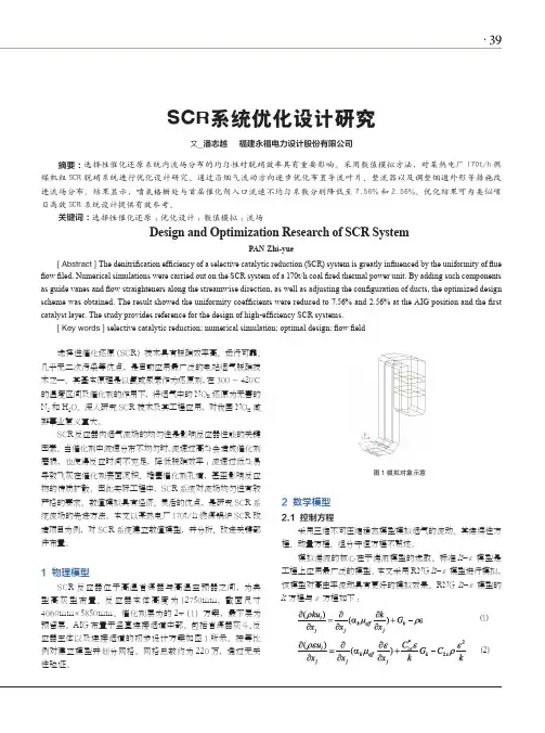
·39SCR系统优化设计研究文_潘志越 福建永福电力设计股份有限公司摘要:选择性催化还原系统内流场分布的均匀性对脱硝效率具有重要影响。
采用数值模拟方法,对某热电厂170t/h 燃煤机组SCR 脱硝系统进行优化设计研究。
通过沿烟气流动方向逐步优化布置导流叶片、整流器以及调整烟道外形等措施改进流场分布。
结果显示,喷氨格栅处与首层催化剂入口流速不均匀系数分别降低至7.56%和2.56%。
优化结果可为类似项目高效SCR 系统设计提供有效参考。
关键词:选择性催化还原;优化设计;数值模拟;流场Design and Optimization Research of SCR SystemPAN Zhi-yue[ Abstract ] The denitrification efficiency of a selective catalytic reduction (SCR) system is greatly influenced by the uniformity of flue flow filed. Numerical simulations were carried out on the SCR system of a 170t/h coal fired thermal power unit. By adding such components as guide vanes and flow straighteners along the streamwise direction, as well as adjusting the configuration of ducts, the optimized design scheme was obtained. The result showed the uniformity coefficients were reduced to 7.56% and 2.56% at the AIG position and the first catalyst layer. The study provides reference for the design of high-efficiency SCR systems.[ Key words ] selective catalytic reduction; numerical simulation; optimal design; flow field 选择性催化还原(SCR)技术具有脱硝效率高、运行可靠、几乎无二次污染等优点,是目前应用最广泛的电站烟气脱硝技术之一。
SCR板式催化剂的制备与脱硝性能实验研究的开题报告标题:SCR板式催化剂的制备与脱硝性能实验研究一、研究背景煤炭、石油等化石燃料的燃烧会产生大量NOx等有害气体,对环境和人体健康都产生危害。
因此,研究减少和消除排放的NOx是非常重要的问题。
SCR(Selective Catalytic Reduction,选择性催化还原)技术是一种有效的减少NOx排放的方法,通常需要利用催化剂将NOx和氨(NH3)一起加入反应器中,通过化学反应将NH3还原成氮气和水,同时将NOx还原为氮气,从而达到减少NOx排放的目的。
SCR技术已被广泛应用于烟气净化系统中,SCR催化剂也是其中的关键组成部分。
板式催化剂是一种具有很高催化反应活性的催化剂形式,能够提高催化反应的速率和效率,并且具有较好的耐高温、抗毒性和可再生等特点,在工业领域得到了广泛应用。
二、研究目的本研究的主要目的是制备SCR板式催化剂,并通过实验研究其对NOx的脱除性能。
具体来说,研究目标包括:1. 制备具有高催化活性和稳定性的SCR板式催化剂,探究不同制备条件对催化剂性能的影响。
2. 研究SCR板式催化剂对NOx的脱除性能,探究不同反应条件(如温度、气体流速等)对脱硝性能的影响。
3. 分析SCR板式催化剂的结构、形貌以及成分分布等特征,并探究这些特征对催化剂性能的影响。
三、研究内容和方法1. 制备SCR板式催化剂:采用浸渍法制备SCR板式催化剂,探究不同的制备条件(如催化剂成分、浸渍次数、浸渍液浓度等)对催化剂性能的影响。
2. 实验研究催化剂的脱硝性能:在实验室环境下,采用模拟烟气的方法,测试SCR板式催化剂对NOx的脱除性能,并探究不同反应条件下催化剂的性能变化。
3. 分析催化剂的结构、形貌以及成分分布等特征:采用扫描电子显微镜(SEM)、X射线粉末衍射(XRD)和X射线光电子能谱(XPS)等技术手段,分析催化剂的结构特征、形貌和成分分布等特征,并探究这些特征对催化剂性能的影响。

Protocol for Laboratory T esting SCR Catalyst SamplesT echnical ReportProtocol for Laboratory Testing SCR Catalyst Samples1012666Final Report, December 2006EPRI Project ManagerD. BroskeELECTRIC POWER RESEARCH INSTITUTE3420 Hillview Avenue, Palo Alto, California 94304-1338 • PO Box 10412, Palo Alto, California 94303-0813 • USA 800.313.3774 • 650.855.2121 • askepri@ • DISCLAIMER OF WARRANTIES AND LIMITATION OF LIABILITIESTHIS DOCUMENT WAS PREPARED BY THE ORGANIZATION(S) NAMED BELOW AS AN ACCOUNT OF WORK SPONSORED OR COSPONSORED BY THE ELECTRIC POWER RESEARCH INSTITUTE, INC. (EPRI). NEITHER EPRI, ANY MEMBER OF EPRI, ANY COSPONSOR, THE ORGANIZATION(S) BELOW, NOR ANY PERSON ACTING ON BEHALF OF ANY OF THEM:(A) MAKES ANY WARRANTY OR REPRESENTATION WHATSOEVER, EXPRESS OR IMPLIED, (I) WITH RESPECT TO THE USE OF ANY INFORMATION, APPARATUS, METHOD, PROCESS, OR SIMILAR ITEM DISCLOSED IN THIS DOCUMENT, INCLUDING MERCHANTABILITY AND FITNESS FOR A PARTICULAR PURPOSE, OR (II) THAT SUCH USE DOES NOT INFRINGE ON OR INTERFERE WITH PRIVATELY OWNED RIGHTS, INCLUDING ANY PARTY'S INTELLECTUAL PROPERTY, OR (III) THAT THIS DOCUMENT IS SUITABLE TO ANY PARTICULAR USER'S CIRCUMSTANCE; OR(B) ASSUMES RESPONSIBILITY FOR ANY DAMAGES OR OTHER LIABILITY WHATSOEVER (INCLUDING ANY CONSEQUENTIAL DAMAGES, EVEN IF EPRI OR ANY EPRI REPRESENTATIVE HAS BEEN ADVISED OF THE POSSIBILITY OF SUCH DAMAGES) RESULTING FROM YOUR SELECTION OR USE OF THIS DOCUMENT OR ANY INFORMATION, APPARATUS, METHOD, PROCESS, OR SIMILAR ITEM DISCLOSED IN THIS DOCUMENT.ORGANIZATION(S) THAT PREPARED THIS DOCUMENTFossil Energy Research Corp.W. S. Hinton and AssociatesNOTEFor further information about EPRI, call the EPRI Customer Assistance Center at 800.313.3774 or e-mail askepri@.Electric Power Research Institute and EPRI are registered service marks of the Electric Power Research Institute, Inc.Copyright © 2006 Electric Power Research Institute, Inc. All rights reserved.CITATIONSThis report was prepared byFossil Energy Research Corp.23342-C South Pointe DriveLaguna Hills, CA 92653Principal InvestigatorsL. MuzioR. SmithJ. MuncyW. S. Hinton and Associates1612 Smugglers CoveGulf Breeze, FL 32563Principal InvestigatorW. S. HintonThis report describes research sponsored by the Electric Power Research Institute (EPRI).The report is a corporate document that should be cited in the literature in the following manner: Protocol for Laboratory Testing SCR Catalyst Samples. EPRI, Palo Alto, CA: 2006. 1012666.iiiPRODUCT DESCRIPTIONSelective catalytic reduction (SCR) is the preferred technology for controlling NOx emissionsfrom coal-fired power plants, particularly when high levels of reduction (80 to 90%) are required. The primary objective of the protocol developed in this project is to define recommended and uniform procedures that SCR system operators can specify when having catalyst performance tests conducted by catalyst vendors and independent testing laboratories. Results & FindingsThe report discusses individually and in depth the recommended protocols for each of the following catalyst test areas:•Catalyst activity: Used to assess the overall potential of SCR reactors for reducing NOx andas an input to catalyst management programs to plan catalyst additions and replacements.•SO2 to SO3oxidation: Used to monitor SO2oxidation and help assess the need for SO3mitigation measures or changes to existing SO3mitigation measures.•Hg oxidation: With upcoming regulations targeting mercury emissions, monitoring a catalyst’s mercury oxidation characteristics will be an vital component of a catalystmanagement plan.•Physical properties: Just as back-end temperature surface area measurements can help explain changes in catalyst activity, so can pore volume and pore size distribution. •Chemical composition: Bulk and surface chemical analyses of the catalyst also assist in diagnosing the cause of normal or abnormal changes in catalyst activity.Challenges & Objective(s)A viable catalyst management strategy depends on continually assessing the rate of catalyst deactivation and accurately estimating activity at any point in time during the life of the catalyst. Although users of SCR systems may depend on a dedicated catalyst vendor to provide this information, as SCR operators begin to purchase catalyst from other vendors who may use different catalyst testing methods, activity data may differ. In addition, data provided by catalyst regeneration vendors also may not be consistent with data from the original catalyst manufacturers. Accordingly, this project addressed the need to develop uniform catalyst testing procedures.vviApplications, Values & UsePotential inconsistencies in catalyst performance data from various sources highlight the need for a catalyst testing protocol that users can specify when contracting with catalyst vendors and laboratories to conduct catalyst performance tests.EPRI PerspectiveWith well over 100-GW of installed SCR capacity in the United States at the time of this writing, the need for a standardized SCR catalyst testing protocol, documented in this report, is ofparamount importance to the coal-fired power-producing industry. The catalyst testing protocol documented in this report is considered dynamic, and updates and revisions to this document will be made as additional findings are discovered.ApproachThe project team developed the catalyst testing protocol formulated in this project using input from industry workgroups in each of the five areas listed in Results & Findings. Workgroup participants came from catalyst vendors, independent catalyst testing laboratories, catalyst reconditioners, industry consultants, and SCR system operators. Additional information was drawn from the German VGB-R302H document (Guideline for the Testing of DeNO x Catalysts ) and its supplement, “Supplement to VGB-R302He 2nd Edition – Common Best Practices for Bench Scale Reactor Testing and Chemical Analysis of SCR DeNo x Catalyst.”KeywordsSCRNOxEnvironmental controlsABSTRACTWith the widespread use of selective catalytic reduction (SCR) throughout the U.S. fleet of coal-fired utility boilers to control NOx emissions, there has been a need to standardize protocols forcatalyst testing. This document recommends a uniform catalyst testing protocol that SCR system operators can follow when conducting catalyst performance tests. The protocol covers five tests:1) catalyst activity, 2) SO2 to SO3oxidation, 3) mercury oxidation, 4) chemical characterization,and 5) characterization of physical properties.viiACKNOWLEDGMENTSA number of organizations and individuals have helped with the development of this laboratory testing protocol of SCR catalyst. The pioneering work in developing SCR laboratory testing procedures was done in Europe by the VGB (1). A recent best practices document was prepared by Steag (2).We acknowledge the help and input from the following individuals and their organizations, in preparation of the current document:Jeff van Aaken (Argillon)Jared Cannon (Southern Company Services)Tom Davey (Consumers Energy)Chris DiFrancesco (Cormetech)Thorsten Dux (E.ON Engineering)Flemming Hansen (Haldor-Topsoe)Keith Harrison (Southern Company Services)Hans Hartenstein (Steag LLC)Juliana Kyle (Southern Company Services)Marilyn Martin (Steag LLC)Kolli Rao (New York Power Authority)Terry Smith (E.ON Engineering)ixxi CONTENTS1 INTRODUCTION AND SUMMARY........................................................................................1-1 Background...........................................................................................................................1-1 Objectives .............................................................................................................................1-2 Summary...............................................................................................................................1-2 Disclaimer..............................................................................................................................1-4 2 DEFINITIONS AND CONVENTIONS.....................................................................................2-13 CATALYST NO X ACTIVITY TESTING...................................................................................3-1Definition of Catalyst Activity.................................................................................................3-1 Measuring Catalyst Activity...................................................................................................3-3 Catalyst Activity Measuring Apparatus..................................................................................3-3 Test Conditions Effects on Catalyst Activity..........................................................................3-3 Selecting Micro or Bench Reactors.......................................................................................3-5 Sample Preparation...............................................................................................................3-5 Documenting Test Sample Dimensions................................................................................3-6 Test Conditions...................................................................................................................3-10 Flow Rate and Velocity...................................................................................................3-10 Temperature...................................................................................................................3-10 Background Gas Composition........................................................................................3-10 NH 3/NO x Ratio.................................................................................................................3-11Conditioning........................................................................................................................3-12 Number of Activity Tests.....................................................................................................3-13 Measurement Methods........................................................................................................3-14 Gas Flow ........................................................................................................................3-14 Temperature...................................................................................................................3-14 Gas Composition............................................................................................................3-14 Data Analysis and Reporting...............................................................................................3-15xii4 SO 2 TO SO 3 OXIDATION........................................................................................................4-1Measurement Issues.............................................................................................................4-1 Rate Equation...................................................................................................................4-1 Conditioning Times...........................................................................................................4-2 Effect of NO x and NH 3.......................................................................................................4-3Measuring SO 2 to SO 3 Oxidation......................................................................................4-3Test Reactor..........................................................................................................................4-3 Test Conditions.....................................................................................................................4-5 Flow Rate and Velocity.....................................................................................................4-5 Temperature.....................................................................................................................4-6 Background Gas Composition..........................................................................................4-6 NH 3/NO x Ratio...................................................................................................................4-6Conditioning..........................................................................................................................4-6 Number of Tests....................................................................................................................4-7 Measurement Methods..........................................................................................................4-7 Measurement of SO 2 to SO 3 Oxidation.............................................................................4-7Data Analysis and Reporting.................................................................................................4-9 5 Hg OXIDATION......................................................................................................................5-1 Background...........................................................................................................................5-1 Mercury Addition...................................................................................................................5-2 Selecting Micro or Bench Reactors.......................................................................................5-2 Test Conditions.....................................................................................................................5-3 Catalyst Volume, Flow Rate and Velocity.........................................................................5-3 Temperature.....................................................................................................................5-4 Background Gas Composition..........................................................................................5-4 Mercury.............................................................................................................................5-5 NH 3/NO x Ratio...................................................................................................................5-5Chlorine............................................................................................................................5-6 Conditioning and Stabilization...............................................................................................5-6 Measurement Methods..........................................................................................................5-7 Mercury Measurement......................................................................................................5-7 Quality Assurance/Quality Control....................................................................................5-8 Test Apparatus Baseline Characteristics..........................................................................5-8Number of Tests...............................................................................................................5-9 Data Analysis and Reporting.................................................................................................5-96 CHEMICAL PROPERTIES.....................................................................................................6-1Background...........................................................................................................................6-1 Catalyst Sampling.................................................................................................................6-1 Bulk Chemical Analysis.........................................................................................................6-2 Sample Preparation and Digestion...................................................................................6-3 Analytical Technique and Specific Analytes.....................................................................6-3 Surface Chemical Analysis....................................................................................................6-3 X-Ray Fluorescence Spectrometry...................................................................................6-3 Other Surface Analysis Techniques.................................................................................6-4 Specific Analytes and Reporting Convention........................................................................6-5 Reporting Requirements.......................................................................................................6-67 PHYSICAL PROPERTIES......................................................................................................7-1Background...........................................................................................................................7-1 Surface Area Analysis...........................................................................................................7-1 Pore Volume and Size Distribution........................................................................................7-2 Mercury Porosimetry........................................................................................................7-2 Gas Adsorption.................................................................................................................7-2 Mechanical Strength..............................................................................................................7-3 Abrasion Resistance.............................................................................................................7-3 Catalyst Geometry.................................................................................................................7-4 Summary...............................................................................................................................7-4 Reporting Requirements.......................................................................................................7-58 REFERENCES.......................................................................................................................8-1xiiixv LIST OF FIGURESFigure 3-1 Calculated Effect of Velocity on Measured Catalyst Activity, K................................3-5 Figure 3-2 Dimensions of Honeycomb Catalyst.........................................................................3-8 Figure 3-3 NO x Conversion and Activity as a Function of Conditioning Time..........................3-13Figure 3-4 Precision in Outlet NO x Measurement as a Function of Variation in K....................3-14Figure 4-1 Effect of SO 2 Concentration and Temperature on SO 2 to SO 3 Equilibration Time...................................................................................................................................4-2 Figure 4-2 Effect of NO x and NH 3 on SO 2 to SO 3 Oxidation.......................................................4-4Figure 4-3 Change in SO 2 or SO 3 Across a Catalyst Sample ....................................................4-4Figure 4-4 Controlled Condensation Sample Train....................................................................4-8 Figure 4-5 Controlled Condensation Condenser Configurations...............................................4-8xvii LIST OF TABLESTable 1-1 Protocol Workgroups.................................................................................................1-2 Table 1-2 Summary: Activity, SO 2 and Mercury Oxidation Protocol ..........................................1-3Table 1-3 Summary: Chemical and Physical Properties............................................................1-4 Table 2-1 Examples of Standard Conditions .............................................................................2-1 Table 3-1 Activity Test Conditions ...........................................................................................3-11 Table 3-2 Workgroup Input on Conditioning Times .................................................................3-12 Table 4-1 SO 2 to SO 3 Conditioning Times (Workgroup Input)....................................................4-3Table 4-2 SO 2 Oxidation Test Conditions ..................................................................................4-5Table 5-1 Mercury Oxidation Test Conditions............................................................................5-3 Table 5-2 Specific Mercury Addition Requirements...................................................................5-5 Table 5-3 Minimum Conditioning/Stabilization Period Guidelines for Continuous MercuryData....................................................................................................................................5-6 Table 5-4 Minimum Conditioning/Stabilization Period Guidelines for Non-ContinuousMercury Data......................................................................................................................5-6 Table 5-5 Mercury Analysis Instruments Commercially Offered................................................5-8 Table 6-1 Catalyst Sampling Guideline—Minimum Requirements............................................6-2 Table 6-2 Primary Bulk and Surface Chemical Analytes and Reporting Convention.................6-5 Table 6-3 Additional Discretionary Bulk and Surface Analytes..................................................6-6 Table 7-1 Common Physical Property Parameters and Test Methods......................................7-51INTRODUCTION AND SUMMARYBackgroundSelective catalytic reduction (SCR) has become the technology of choice for the control of NOx emissions from coal-fired power plants, particularly when high levels of reduction (80 to 90%)are required. A catalyst management strategy is needed to address the consequences of catalystdeactivation over time. This catalyst management strategy depends on an ongoing assessment ofthe rate of catalyst deactivation and an accurate estimate of activity at any point in time. Someusers of SCR systems may depend on a dedicated catalyst vendor to provide this activityinformation as an integral part of a catalyst supply contract. However as SCR operators begin topurchase catalyst from other vendors which may use different catalyst testing methods, theactivity data from one supplier might not agree with data from another. Additionally, the dataprovided by catalyst regeneration vendors may not be consistent with data from catalyst OEMvendors. The inconsistencies in catalyst performance data from various sources points to theneed for a catalyst testing protocol that users can specify when they contract with catalystvendors, or laboratories, to conduct catalyst performance tests.There are many aspects of catalyst testing for SCR applications; as such, the current protocolcovers the following area pertaining to catalyst testing:•Activity – Used to assess the overall potential of the SCR reactor for reducing NOx , and isalso used as an input to catalyst management programs to plan catalyst additions and/or replacements.•SO2 to SO3Oxidation – Used to monitor SO2oxidation, and aids in assessing the need forSO33mitigation programs.•Hg Oxidation – With upcoming regulations aimed at controlling mercury emissions, utilities will begin to look to the oxidation of mercury across the SCR catalyst with subsequentremoval in a downstream wet FGD system, for mercury control. Thus, monitoring themercury oxidation characteristics of the catalyst will also be an important part of a catalyst management plan.•Physical Properties – Such as BET surface area, pore volume and pore size distribution assist in the explanation in changes in catalyst activity.•Chemical Composition – Bulk and surface chemical analyses of the catalyst also assist in the diagnosis of the cause for normal or abnormal changes in catalyst activity.Introduction and SummaryThe catalyst testing protocol formulated in this project has been developed using input from industry workgroups in each of the areas listed above. The workgroup participants were drawn from catalyst vendors, independent catalyst testing laboratories, catalyst reconditioners, industry consultants, and operators of SCR systems. In addition, the German VGB-R302H document (Guideline for the Testing of DeNO x Catalysts) provided by the Technical Association of LargePower Plant Operators in Germany (1) and a supplement authored by Steag (2)“Supplement toVGB-R302He 2ndEdition – Common Best Practices for Bench Scale Reactor Testing andChemical Analysis of SCR DeNo x Catalyst” were drawn upon where appropriate. Table 1-1 lists the workgroups and organizations that participated in each group.This document is not considered a finalized protocol. It is considered dynamic as updates and revisions will be made as technology improves.Table 1-1Protocol WorkgroupsCatalyst ActivitySO 2 to SO 3Oxidation Mercury Oxidation Chemical and PhysicalPropertiesEPRI EPRI EPRI EPRI FERCo FERCoW.S. Hinton andAssoc. W.S. Hinton and Assoc.Southern Company Southern Company Southern Company Southern Company Steag LLC Steag LLC Steag LLC Steag LLC E.ON EngineeringE.ON EngineeringE.ON EngineeringE.ON EngineeringHaldor-Topsoe Haldor-Topsoe Haldor-Topsoe Haldor-Topsoe Cormetech Cormetech Cormetech Cormetech Consumers Energy ArgillonArgillon New York PowerAuthorityNew York Power AuthorityObjectivesThe primary objective of this protocol is to present recommended and uniform procedures that operators of SCR systems can specify when having catalyst performance tests conducted bycatalyst vendors and/or independent testing laboratories. The recommended protocols for each of the test areas outlined above will be discussed individually in the following sections.SummaryAn overall summary of the catalyst testing protocol for catalyst activity, SO 2 to SO 3 oxidation, and mercury oxidation is shown in Table 1-2. Note the protocol specifies that the tests beIntroduction and Summaryconducted on a bench-scale apparatus and that catalyst from each full-scale catalyst layer be tested separately. A summary covering the determination of physical and chemical properties of the catalyst is shown in Table 1-3.Table 1-2Summary: Activity, SO 2 and Mercury Oxidation ProtocolTest Parameter ActivitySO 2 Oxidation Hg OxidationApparatus Bench Scale ReactorSample Size Honeycomb/CorrugatedPlate150mm x150mm x Full Layer Length 150mm x150mm x Half Full Layer LengthTemperatureFull ScaleFlow Match Full Scale Linear VelocityO 2 Full Scale H 2O Full ScaleCO 2 As generated by combustion sourceSO 2 Full Scale NO x Full ScaleSO 3 None AddedFull Scale HCl 0 Full ScaleNH 3/NO x 1.0 00.9 and 0 Conditioning Time 12 hrs or Equilibrium 48 hrs orEquilibriumNH 3 off after Activity Test for 8 hrsNew: 48 hrs Used: 4 hrs Measurements ∆NO x ∆SO 3 or ∆SO 2∆Hg elementalNo. of Tests 4 3 3CalculationsK=-A v ln(1-∆NOx)%SO 2 OxidationK SO2= Q/m cat ln(1-∆SO 2)% Hg OxidationIntroduction and SummaryTable 1-3Summary: Chemical and Physical PropertiesChemical PropertiesBulk Analysis Atomic Absorption (AA) Inductively Coupled Plasma (ICP) Wet ChemicalSurface Analysis X-Ray Fluorescence (XRF) Electron MicroscopeSpecies of InterestAl2O3, As, CaO, Fe2O3, P2O5, K2O, MgO, MoO3,Na2O, SiO2, TiO2, V2O5, WO3Physical PropertiesParameter Preferred Test MethodSurface Area Single-Point BET using NitrogenPore Volume and Distribution Hg Porosimetry or Gas AdsorptionMechanical Strength Per Manufacturer RecommendationDelamination Resistance Per Manufacturer RecommendationAbrasion Resistance Per Manufacturer RecommendationGeometry DirectDimensionalMeasurement DisclaimerThe catalyst testing protocol documented in this report has been formulated based on input fromthe Workgroup participants as well as information contained in references 1 and 2. The protocolhas as yet not been experimentally validated. Experimental validation is expected as feedback isreceived from users of the protocol.。
scr设计标准SCR(Selective Catalytic Reduction)是一种重要的环保技术,用于减少工业和电力生产等过程中的氮氧化物(NOx)排放。
SCR系统的设计需要遵循一定的标准和规范,以确保其运行稳定、效果良好,同时符合国家及地方的环保要求。
1.确定设计参数在设计SCR系统时,首先要确定需要处理的气体成分、流量、温度、压力等参数,以及所需的脱硝效率。
根据这些参数选择合适的催化剂和反应器结构,并确定催化剂的装填量。
2.选择催化剂催化剂是SCR系统的核心组成部分,其选择直接影响到系统的脱硝效率和运行稳定性。
催化剂的主要类型包括贵金属催化剂、金属氧化物催化剂和分子筛催化剂等。
选择催化剂时需要考虑其活性、选择性、抗毒性和使用寿命等因素。
3.设计反应器结构反应器是SCR系统中的重要设备,其结构需要根据处理气体的流量、压力、温度等参数以及所需脱硝效率进行设计。
反应器一般采用垂直布置,根据需要可设置多个催化剂床层。
设计反应器时要确保气流分布均匀,避免出现死区和短流等问题。
4.确定操作条件SCR系统的操作条件也会影响其脱硝效率和稳定性。
操作条件包括温度、压力、气体成分、流量等参数。
在系统设计时,需要根据实际情况确定合适的操作条件,以保证系统的正常运行。
5.考虑安全措施SCR系统在运行过程中存在一些安全隐患,如催化剂中毒、堵塞和磨损等问题。
因此,在设计系统时需要考虑到安全措施,如设置过滤器去除气体中的杂质,设置防爆板防止爆炸等。
6.符合环保要求SCR系统的最终目的是减少污染物的排放,因此其设计必须符合国家及地方的环保要求。
在系统设计时需要考虑到排放物的成分、浓度和排放量等参数,确保系统能够达到环保标准。
总之,SCR系统的设计需要遵循一定的标准和规范,以确保其运行稳定、效果良好,同时符合国家及地方的环保要求。
在系统设计时需要考虑到各种因素,包括确定设计参数、选择催化剂、设计反应器结构、确定操作条件、考虑安全措施以及符合环保要求等。

提高电机设计的效率水平
Eric Zhang
【期刊名称】《中国电子商情·基础电子》
【年(卷),期】2010(000)011
【摘要】@@ 随着节能成为全球范围关注的焦点,电机设计的能效也成为一个引人关注的问题.由于各国政府相继出台各种法规来要求提高能效,为了应对能效挑战,电机驱动电路变得越来越复杂.本文将讨论电机驱动电路产品、行业趋势,以及有助于设计人员降低能耗,提高可靠性、减少部件数目及实现环保的解决方案.
【总页数】3页(P50-52)
【作者】Eric Zhang
【作者单位】飞兆半导体公司
【正文语种】中文
【相关文献】
1.影响电机效率的因素及现实中提高电机效率的方法浅析 [J], 呼朝
2.改进回路,阀组及电机优化设计可经济快速提高压缩机效率 [J], 陆海江
3.充分发挥CAD的优势提高电机设计的质量和效率 [J], 余海刚;陈兰瑛
4.提高电机设计的效率水平 [J], Eric Zhang
5.罗克韦尔自动化新型伺服电机助力提高机器性能Kinetix VPC伺服电机有助于提高连续工作应用的生产率和效率 [J],
因版权原因,仅展示原文概要,查看原文内容请购买。
光电二氧化碳还原催化剂的设计与优化随着全球气候变化问题的日益严峻,寻找可持续能源和减少二氧化碳排放已成为当今科学界的重要课题。
光电二氧化碳还原催化剂作为一种潜在的解决方案,引起了广泛的关注和研究。
本文将探讨光电二氧化碳还原催化剂的设计与优化。
光电二氧化碳还原催化剂是指能够利用光能将二氧化碳转化为有用化合物的催化剂。
在这个过程中,催化剂起到了关键的作用,它能够降低反应的能垒,提高反应速率,从而实现高效的二氧化碳还原。
因此,设计出高效的催化剂成为了研究的重点。
在光电二氧化碳还原催化剂的设计中,首先要考虑的是催化剂的光电性能。
光电性能是指催化剂在光照条件下的光吸收和电子传输能力。
一般来说,高光吸收能力和快速电子传输能力是设计光电催化剂的关键要素。
为了提高光吸收能力,可以选择具有宽带隙的半导体材料作为催化剂的基底。
而为了提高电子传输能力,可以通过调控催化剂的能带结构和晶体结构来实现。
此外,还可以引入共催化剂或修饰剂来优化光电性能。
其次,催化剂的表面活性位点也是设计光电催化剂的重要方面。
活性位点是指催化剂表面上能够吸附和催化反应的位置。
在二氧化碳还原反应中,常用的活性位点包括金属离子、缺陷位点和边界位点等。
金属离子通常具有较高的催化活性,因为它们能够提供丰富的反应中心和调控反应的电子结构。
而缺陷位点和边界位点则能够提供更多的吸附位点和反应中心,从而提高反应速率。
因此,在催化剂的设计中,需要选择合适的活性位点,并通过调控催化剂的结构和组成来实现。
最后,催化剂的稳定性也是设计光电催化剂的重要考虑因素。
由于光电二氧化碳还原反应通常是一个长期的过程,催化剂需要具有良好的稳定性才能保持高效的催化活性。
为了提高催化剂的稳定性,可以选择稳定的材料作为催化剂的基底,并通过合适的修饰剂来增强催化剂的稳定性。
此外,还可以通过调控催化剂的晶体结构和表面修饰来提高催化剂的稳定性。
综上所述,光电二氧化碳还原催化剂的设计与优化是一个复杂而关键的过程。
Optimizing SCR Catalyst Design and Performance for Coal-Fired BoilersScot PritchardChris DiFrancescoCormetech, Inc.Durham N.C(919) 620-3000Shozo KanekoNorihisa KobayashiMitsubishi Heavy Industries, Ltd.Nagasaki, Japan(045) 224-9178Kohei SuyamaKozo IidaMitsubishi Heavy Industries, Ltd.Nagasaki, Japan(958) 28-6401Presented atEPA/EPRI 1995Joint SymposiumStationary Combustion NOx ControlMay 16-19, 1995OPTIMIZING SCR CATALYST DESIGNAND PERFORMANCE FOR COAL-FIRED BOILERSScot PritchardChris DiFrancescoCormetech, Inc.5000 International DriveDurham, NC 27712Shozo KanekoNorihisa KobayashiMitsubishi Heavy Industries, Ltd.Yokohama, JapanKohei SuyamaKozo LidaMitsubishi Heavy Industries, Ltd.Nagasaki, JapanAbstractThe design of an SCR system for a coal-fired application is a challenge due to particulate, catalyst poisons, and So2 in the flue gas. Our experience show that coal-fired SCRs are successful when the system impact and catalyst deterioration factors are understood and specific countermeasure are implemented in system and catalyst designThere are several factors that the system and catalyst must consider in order to assure success. They include: type of boiler, required performance, fuel and ash analysis, ash loading, type of SCR, inlet conditions, Catalyst deactivation mechanisms and impact on down stream equipment.This paper explains each system and catalyst deterioration factor that we have experienced. For each factor, it presents the specific countermeasure that has resulted in successful SCR systems. Also, it discusses the design of improved catalyst derived from our experience. Finally, two case studies illustrate the impact of optimized design.IntroductionSelective Catalyst Reduction (SCR) is recognized worldwide as the most effective NOx Control Technology for utility boilers and combustion turbines when substantial NOx reduction of 50% to 95% is required. In addition to its proven high performance, It has also become an economically viable solution, with current installed cost, in the United States, estimated at between $20/kw for natural gas and $50/kw-$70/kw for coal units. The technology has even given some utilities the capability to achieve lower heat reduction or omission of flue gas recalculation (FGR).Mitsubishi Heavy Industries (MHI) pioneered the developed and application of SCR technology staring in the late 70’s in Japan, and installed the worlds’ first High-dust SCR application on a 175 MW coal fired boiler in 1980. MHI transferred their technology through licensing agreement to several companies in Europe and to Cormetech in the United States. Over 319 units including 56 coal fired boilers worldwide operation successfully using this technology.Figure 1Catalyst for Coal, Oil, and Gas ApplicationsCormetech is a joint equity company of Corning Incorporated, MHI, and Mitsubishi Chemical Company (MCC). Cormetech design and Manufactures homogeneous Titanium-Tungsten-Vanadium (Ti-W-V), Extruded honeycomb catalyst for fossil-fuel-fired applications. Figure 1 show a photograph of catalyst for coal, oil, and gas applications. Cormetech draws upon the vast experience database of MHI, the extrusion and catalyst know-how of corning, and catalyst technology of MCC to provide an optimized product to the market.This paper address the methods successfully implemented to design and optimize catalyst performance in coal fired boiler applications. The basics of deNOx catalysis arereviewed in preparation for the discussion on system impact, catalyst deterioration,mechanism, and countermeasures that follows. Additionally, catalyst designoptimization is presented by a discussion of improved catalysts for coal applications.Two case studies (pulverized coal and cyclone boilers) comparing conventional andimproved catalyst are presented.Background of SCR ReactionIn coal fired boilers in which SOx is presented in the flue gas two chemical reaction thatoccur in the presence of the SCR catalyst are of most importance to the followingdiscussionOne reaction, of course, is the deNOx reaction:4NO + 4NH+ O2 2 +6H2O(1) Figure 2 illustrates this primary reaction mechanism. Starting in the upper left-handcorner of the figure and proceeding clockwise is:1. Active catalyst site (Me = metal)2. Absorption of ammonia molecule3. Reaction of NO with NH3 forming4. Regeneration of active site by oxidationThe second reaction is oxidation of sulfur dioxide:(2) SO+ ½ O SO3The NOx conversion rate and SO2 oxidation rate will partly depend upon the rate inwhich the reactants diffuse through the wall of the porous catalyst to reach active siteswhere reaction takes place. Through our experience we have determined the rate ofchemical reaction is fast reaction for our catalyst. For deNOx conversion the rate ofchemical reaction is fast relative to the rate of diffusion. Therefore the catalyst iseffective primarily at the surface of the wall. On the other hand, the SO2 oxidationchemical reaction rate is slow relative to the rate of diffusion so that the reactants diffuseinto the entire wall. This conclusion is relevant to the subsequent discussion on thesystem impacts, catalyst deterioration mechanisms, and countermeasures.HRegeneration of Active SiteReaction of NO with NH3Figure 2SCR Surface Reaction MechanismFigure 3SCR ConfigurationsSystem Design Impact & CountermeasuresFigure 3 shows two typical layout of SCR system applied to coal fired boilers. The Low-Dust or Tail End option shows the installation of the SCR reactor after the air preheater (APH), Electrostatic Precipitator (ESP), and flue Gas Desulfurization (FGD) systems. This option requires the flue gas to be reheated to acceptable SCR temperatures, typically 5500F-7500F. Low-Dust designs have primarily been used on wet bottom boilers which have ash re-circulation, due to concern over catalyst degradation caused by arsenic poisoning. The High-Dust option locates the SCR reactor between the economizer exit and the AOH inlet. This is more traditional for dry bottom boilers and less costly, and is now being applied to wet bottom boiler based on economics, advancements in catalyst resistance to arsenic poisoning, and limestone addition to the fuel, which will be discussed later.Figure 4SCR ComponentsThe SCR system consists of many components in addition to the catalyst. Figure 4 depict a high-dust SCR system which includes the catalyst reactor, economizer bypass used for part-load temperature control, static mixer used for temperature and/or ammonia mixing, turning vanes, ammonia vaporization system, ammonia injection grid (AIG), sootblower, and the control system. Since these components directly influence overall system effectiveness, Cormetech works closely with system equipment suppliers to ensure proper design.Operational impact of an SCR system on coal fired boilers included drafts loss, SO3 formation, and ammonia emission, Pressure drop is caused by the installation of the catalyst material in the flue gas and is typically minimized by expanding the flue gas path. Typical pressure value for conventional high dust applications range from 0.5 to 1inch of water per catalyst layer, with 2-3 layers installed with an additional 1-2 inches for the components of the system.As shown in equation (2) the SCR catalyst will convert a small amount of SO2 to SO3. This conversion rate is typically less than 0.55 per layer depending upon the catalyst formulation, deNOx requirements, and operating temperature. If the SO2 oxidation rate is too high, corrosion and plugging will occur in the (APH) due to the formation of H2SO4 and NH4HSO4.As a countermeasure, our catalyst is designed to achieve high deNOx activity while keeping SO2 oxidation activity low. When considering the catalyst formulation, a high concentration of vanadium will result in a high deNOx activity, but will also result in a high SO2 oxidation activity. One countermeasure to this is a vanadium concentration is selected such that there is sufficient deNOx activity with an acceptable level of SO2 oxidation.As a system countermeasure, the cold end surface of regenerative-type APH may be enameled and/or sootblowing capabilities may be enhanced.Ammonia slip may contaminate flyash, and combination with S03 caused (APH) plugging. Designers can combat the effect by considering:• 2ppm to 5ppm NH3 slip at end-of-life• ammonia injection grid with adequate representative NOx input value to control system• multi-point outlet NOx sampling control grid to assure representative NOx input value to control system.• permanent measuring grid for AIG tuning to assure proper distribution of ammonia • Flyash ammonia concentration monitoring.Catalyst Deterioration Mechanisms & CountermeasuresWhen designing for a given application, designers must carefully review fuelAnd ash constituents (see Table A). Under ideal conditions the catalyst will reduce NOx for an unlimited period of time. (Table B) lists the primary deterioration mechanisms versus the type of coal fired units, wet or dry bottom.Ash Moisture, % 6-33Total Sulfur in Coal, % 0.6-1.6*Trace Material, ppmNi 3-40Cr 7-46As 1-251,900Cl 41-Ash analysis, %Sl O2 41-71As2 O3 2-33Fe2 O3 2.5-10CaO 2.4-26MgO 0.7-49Ti02 0.1-1.8MnO 0.02-0.2V2 05 0.01-0.1Na2 O 0.05-1.6K2O 0.1-4.0P2 O6 0.06-1.3SO3 1.6-16.5*Application Experience on Oil up 5.4% SulfurTable ATypical Fuel/Ash CompositionBoiler Type Wet Bottom Dry BottomNegligible Sintering NegligibleAccumulation of Alkaline Metal Small SmallLarge LargeAccumulation Earth MetalMaskingAccumulation of Arsenic Oxide Large with Ash Re-circulation ModerateFlyash Deposition* Small SmallSmall Erosion* Small*Highly dependent on proper design of SCR systemTable BMain Causes of Catalyst DeteriorationBased on a sound understanding of the deterioration mechanisms, specific countermeasures are implemented, such as:◆ system design evaluation. ◆ catalyst formulation.◆ catalyst volume selection. ◆ catalyst geometry.◆ catalyst macro and micro pore design.◆ catalyst characterization testing and predictive tools.Thermal SinteringThermal sintering is the growth of primary catalyst particle resulting in a reduction of catalyst surface area, which reduces catalyst performance. Figure 5 illustrates this mechanism. Thermal stability is maximized with the corporation of Tungsten in the catalyst formulation. As a result, sintering is negligible at normal SCR operatingtemperatures.TIO2FRESH CATALYSTHEAT SINTERED CATALYSTFigure 5Thermal SinteringAlkaline Metal (Na, K)Alkaline metal may directly react with active sites and render them inert as shown in Figure 6. Since the deNox reaction takes place primarily on the surface, the degree of deactivation depends on the surface concentration of the alkaline metals. In a water-soluble form, these alkaline metals are highly mobile and will migrate throughout the catalyst material. Since the wall of our catalyst consists entirely of catalyst material, the surface concentration of alkaline metal is diluted by this migration, minimizing the deactivation rate.FRESH CATALYSTNa (K)OO--Me--O- -Me--AKALINE DETERIORATIONNa + (K =)Figure 6Alkaline Deterioration MechanismFor the subject catalyst in coal-fired applications, it is our experience that this type of poisoning has a small impact, since most of the alkaline metals in the coal ash are not water soluble. The impact is larger in oil-fired applications where the majority of the alkaline metals in the ash are water-soluble or when the thickness of the catalystmaterial is low. For example, given the same concentration of alkaline metals in the flue gas, this catalyst will have a lower surface poison concentration than a coated product and, thus have a lower deactivation rate and longer useful life as shown in Figure 7.N O x R e m o v a l E f f i c i e n c y , (%)1020304006080100Operation Period (‘000 hrs)Figure 7Comparison of Durability (Oil Firing)Arsenic (As)Arsenic poisoning is caused by gaseous arsenic As2O3 in the flue gas. The As2O3 diffuses into the catalyst and solidifies on both active and non-active sites, as shown in Figure8.As with alkaline metals, arsenic poison is best abated by use of homogenous catalyst compositions, which effectively reduce the surface poison concentration. Since the mechanism of arsenic poisoning is more diffusion-limited and subject to capillary condensation, optimized catalyst pore structure also lessens its effects. Further, engineers use accumulation rates determined by both lab and field tests to ensure a proper catalyst volume is provided for each specific application.Figure 8Model of Arsenic Compound AccumulationA system countermeasure incorporates the use of a fuel additive. As mentioned previously, wet bottom boiler with 100% ash recalculation present a worst case scenario for catalyst deterioration caused by arsenic poisoning. In order to combat the high levels of gaseous arsenic (As2O3) in cyclone boilers, limestone may be added to the fuel. A typical limestone to fuel ratio is approximately 1:50. Figures 9a, 9b, and 10 show how the addition of limestone effectively reduces gaseous arsenic at the entrance to the catalyst. The free CaO in the limestone reacts with arsenic, forming a solid, Ca (AsO4) that will not poison the catalyst. The impact of adding limestone will be addressed further in the wet bottom boiler case study.Figure 9aArsenic Compound in Flue GasEffect of Limestone Injection131030G a s e o u s a r s e n i c @ 1s t C a t a l y s t L a y e r (m i c r o g r a m s /N m 3)Arsenic in Coal (mg/kg)Figure 10Relationship Between Arsenic in Coal and Gaseous ArsenicAlkaline Earth Metals (Ca)Alkaline earth metal poisoning primarily occurs when free CaO in the flyash reacts with SO 3 adsorbed on the catalyst surface forming CaSO 4. The CaSO 4 may cause catalyst surface masking, preventing the reactants from diffusing in to catalyst surface masking, preventing the reactants from diffusing into catalyst. Figures 11 and 12 illustrate this mechanism.FRESHCALCIUM DETERIORATIONFigure 11Mechanism of Calcium DeteriorationCatalyst WallFigure 12Accumulation of calcium Composition in CatalystIn order to address masking, particularly in dry bottom boilers where the free CaO content is nearly double that wet bottom boiler (see Figure 13), characterization of the mechanism and accurate prediction of deactivation rates is employed. Experience shows that quantity of free CaO in the fly ash governs the amounts of deactivation. Extensive modeling of deactivation from full scale and laboratory data has been development providing high confidence in design to counter this phenomenon.ABC D E G H I F Wet Bottom Boiler Ash Dry Bottom Boiler AshFigure 13Free CaO Ratio in Fly AshCatalyst PluggingCatalyst plugging has two primary causes: (a) ammonia salt deposition and (b) flight deposition. Proper selection of catalyst pitch and cell opening size minimizes plugging. Good system design is also a primary prevention tool.Ammonia salt formation/deposition will not occur provided the SCR inlet temperature maintained above the salt formation level. Typically temperature maintenance is only a problem during part load operation and is elevated by installing a water- or gas-side economizer bypass in the system. If a gas bypass is used, careful attention must be paid to provide adequate temperature mixing upstream of AIG.This avoids low temperature streamline, which can cause localized salt formation at the AIG and catalyst.Flight deposition is minimized through proper flow distribution across the catalyst face. This accomplished through engineering of SCR system flue layout, Computational Fluid Dynamics (CFD) codes, and/or cold flow modeling.The design limit the number of areas where dust accumulation may occur, i.e.,• Avoiding flat surface as long leading edge to turning vanes.• Installing as deflection devices on support beam flanges and sootblower pipes.• Avoiding flue dead between dampers where ash accumulation may occur in closed position and exhaust onto catalyst when opened, etc.ErosionCatalyst erosion is caused by the impingement of flyash on the catalyst face.Catalyst erosion is a function of gas velocity, ash character, angle of impingement, and catalyst properties. Cormetech has experience with flyash loading as high as 30g/Nm3 and flue gas velocities up to 6.2 m/s.Experience has proven that no significant erosion will occur with proper system design, catalyst material durability, and catalyst edge hardening. Poor flow and ash distribution at the inlet to the catalyst has been the source of most problems, and has improved significantly over the entire SCR experience history. Careful attention must be paid to utilize flow modeling (CFD and cold flow rectifier grid should be installed to straighten flow into the catalyst bed. Since most catalyst erosion occurs at the catalyst leading edge, which is exposed, to the direct impingement of dust particle the catalyst may also be hardened at the entrance region to provide further protection as shown in Figure 14.CATALYSTFigure 14Honeycomb Catalyst with Hardened EdgeAlthough in most cases In-Duct SCR is not attractive due to extremely high system draft loss and difficulty in control of gas flow and ammonia distribution, some utility site are considering the concept due to site plan limitations. Therefore, we will pilot test our hardened edge catalyst at velocities > 12m/s in 1995.Catastrophic Failure of SCR CatalystCatastrophic Failure is defined as sudden and permanent loss of catalyst performance based on our experience, catastrophic failure are extremely rare. The primary cause is associated with the ignition of ash buildup. The intense heat of a fire can irreversibly damage any SCR catalyst. Cormetech’s ceramic honeycomb catalyst, unlike plate catalyst with stainless steel mesh substrates, will not promote oxidation; therefore fires are less likely to spread and are more easily contained.Coal Catalyst DevelopmentsBased on our understanding of reaction and deactivation mechanisms we are improving our catalyst. The objective is to increase the deNOx reaction rate without increasing the SO2 oxidation rate. One method is to modify the pore structure of the catalyst wall in order to reduce diffusion resistance. The other is novel method and requires further explanation.Since the deNOx reaction is only effective at the surface, we have developed an improved catalyst of the same composition as our conventional catalyst with the exception that the vanadium is preferentially distributed to the surface if the catalyst wall. In this manner, we can maximize the concentration of vanadium in the effective fraction of the wall, maximizing deNOx activity without incurring high SO2 oxidation. Figure 15 shows the performance of this improved catalyst compared to that of conventional catalyst. Since the product is still made entirely of catalytic material, resistance to poisons in maintained.Figure 15Comparison of Catalyst PerformanceDevelopment and Qualification of Improved Coal CatalystsWe are developing the improved coal catalyst described according to the schedule shown in Figure 16.Improved Coal Catalyst R&D ScheduleWe have already completed laboratory performance confirmation and durability tests. The performance of the improved catalyst is approximately 15% higher that our conventional catalyst, without impact on SO2 oxidation.We have tested durability to gaseous arsenic poisoning by an accelerated method using the apparatus in Figure 17. The test results are shown in Figure 18. The improved catalyst maintains its performance advantage over conventional catalyst at any arsenic poisoning level.STFigure 17Schematic of Arsenic Testing ApparatusAc t i v i t y Arsenic Load, ppm*hrFigure 18Arsenic DurabilitySince the degree of Deactivation due to surface masking by CaSO 4 is dependent only on the fraction of surface masked we expected that the rate is deactivation is the same for both conventional and improved catalyst. Therefore, given the same installedcatalyst volume, the improved catalyst will maintain field performance much longer due to the higher initial activity, as shown in Figure 19.TIME, yearsA C T I V I T YFigure 19CaO DurabilityBefore Commercialization, the endurance of the catalyst will be confirmed by operation in actual plant. Initial endurance tests will start by charging catalyst samples intocommercial SCR plants in Japan. During 1995 catalyst samples will be charged into a coal unit in the United States and three coal units in Germany. The performance of the catalyst sample after aging in the commercial plants will be compared to fresh performance in order to evaluate endurance.Impact of Improved Coal Catalyst on SCR Design for Coal FiredWhether achieving an increase in performance by optimizing the pore structure of the catalyst on the SCR design, two SCR case studies are described below comparing improved with conventional catalyst.Case Study 1: Dry Bottom BoilerA 250 MW unit is selected as an example unit. Table C shows the design data for thisunit. Figure20 shows the 10-year catalyst volume of the improved catalyst is higher by15%; the catalyst volume of the improved catalyst is decreased by approximately 15%from the conventional catalyst volume.Design Condition;Fuel CoalPlant Output, MW 250Flue Gas FlowRate,Nm3/hr 784,000NOx inlet, ppmvd @ 3% O2 154NOx outlet, ppmvd @ 3% O2 31NOx Removal Efficiency, % 80Ammonia Slip, ppmvd @ 3% O2 5Specification:Type of System SCRType of Reactor Vertical Flow-Fixed BedType catalyst HoneycombNumber of reactor 1Table CDry Bottom BoilerCatalyst Volume RatioOperating YearsFigure 20Impact of Improved CatalystDry Bottom BoilerCase Study 2: Wet Bottom with Ash RecalculationA 320 MW unit is selected as an example unit. Table D shows data for this unit. Figure21 shows the 10 years catalyst management plan. The total catalyst volume of the improved catalyst for ten years of operation is two-thirds that of the conventionalcatalyst. The impact on the catalyst management plan is shown in Figure22. With Limestone Injection, the need for addition and replacements of catalyst are significantly delayed.Design Condition CoalFuel 320Plant Output, MW 1,125,000Flue Gas Flow Rate,Nm3/hr 1,652NOx Inlet, ppmvd @ 3% O2 530NOx removal efficiency, % 68Ammonia Slip, ppmvd @ 3% O2 5Flash recalculation Rate, % 100Specification:Type of System SCRType of Reactor vertical flow-fixed bedType of Catalyst honeycombNumber Of Reactors 1Table DWet Bottom BoilerOperating Years1234Catalyst Volume RatioFigure 21Impact of Improved CatalystWet Bottom BoilerOperating Years1234Catalyst Volume RatioFigure 22Impact Of LimestoneWet Bottom BoilerConclusionsOur experience shows that coal-fired SCRs are successful when proper attention is paid to system and catalyst design.Proper system design is crucial to Maximizing Catalyst performance potential and achieving lowest annualized cost.By exploiting the experience and know-how gained on existing facilities it is possible to further optimize catalyst design.。