Expanding the capabilities of the Ten-Percent Rule for the strength of fibre-polymer composites,
- 格式:pdf
- 大小:395.63 KB
- 文档页数:46

介绍云计算的英语作文Cloud computing is a revolutionary concept that has transformed the way we access and process data. It refers to the delivery of computing services over the internet, which includes servers, storage, databases, networking, software, analytics, and intelligence. This essay will explore the fundamentals of cloud computing, its benefits, and itsvarious deployment models.Fundamentals of Cloud ComputingCloud computing operates on a simple principle: instead of having a physical server or a local storage device, users can access a shared pool of computing resources over the internet. This is similar to how electricity is provided as a utility, where you only pay for what you use. The infrastructure is maintained by a cloud provider, which handles everything from data storage to processing power.Benefits of Cloud Computing1. Cost Efficiency: One of the most significant advantages of cloud computing is cost savings. It eliminates the need for businesses to invest in expensive hardware and software, as they can rent these resources as needed.2. Scalability: Cloud services can be easily scaled up ordown based on the demand. This flexibility allows businessesto handle sudden spikes in traffic without worrying about infrastructure limitations.3. Accessibility: Data and applications are accessible from anywhere with an internet connection, which is particularly beneficial for remote teams and global enterprises.4. Reliability and Redundancy: Cloud providers typicallyoffer high levels of reliability and redundancy, ensuringthat your data is backed up and always available.5. Maintenance and Updates: Cloud providers are responsiblefor maintaining the servers and software, which means that users do not have to worry about updates and patches.Deployment ModelsThere are three primary deployment models for cloud computing:1. Public Cloud: This is the most common model where services are provided over the public internet. Amazon Web Services (AWS), Microsoft Azure, and Google Cloud Platform are examples of public cloud providers.2. Private Cloud: In this model, the cloud infrastructure is operated solely for a single organization, which can be managed by the organization itself or a third-party service provider.3. Hybrid Cloud: This combines elements of both public and private clouds, allowing for greater flexibility and theability to move workloads between the two environments. ConclusionCloud computing has become an integral part of modern IT infrastructure. It offers a range of benefits that make it an attractive option for businesses of all sizes. As technology continues to evolve, the adoption of cloud computing is expected to grow, further expanding the capabilities and services available to users around the world.。

关于1g到5g时代的发展历程作文英语全文共3篇示例,供读者参考篇1The Evolution from 1G to 5G: A Journey of Advancements in Mobile TechnologyIntroduction:The world of mobile technology has witnessed numerous advancements over the years, from the inception of the first generation (1G) of mobile networks to the current era of 5G technology. These developments have revolutionized the way we communicate, share information, and connect with the world. In this article, we will delve into the evolution of mobile technology from 1G to 5G, exploring the key milestones, features, and benefits of each generation.The First Generation (1G) - The Beginnings of Mobile Communication:The first generation of mobile networks, known as 1G, marked the beginning of mobile communication in the early 1980s. It introduced the concept of wireless voice calls, enabling users to make and receive calls on the go. 1G networks wereanalog and had limited capacity, leading to poor call quality and reliability. Additionally, 1G devices were large and bulky, with limited battery life.Despite these limitations, 1G laid the foundation for the future development of mobile technology and paved the way for the subsequent generations of mobile networks. It was a significant leap forward in terms of communication and connectivity, bringing mobile technology to the masses.The Second Generation (2G) - The Rise of Digital Communication:The second generation of mobile networks, known as 2G, emerged in the early 1990s and introduced digital communication to the world. 2G networks were based on digital technology, offering improved call quality, data transmission, and security. This paved the way for the introduction of new services such as text messaging (SMS) and multimedia messaging (MMS).One of the key innovations of 2G technology was the introduction of Global System for Mobile Communications (GSM), a standardized digital technology that enabled seamless communication between different networks and devices. This laid the groundwork for the global adoption of mobiletechnology and set the stage for further advancements in mobile communication.The Third Generation (3G) - The Era of Mobile Data:The third generation of mobile networks, known as 3G, arrived in the early 2000s and brought mobile data services to the forefront. 3G networks offered faster data speeds, allowing users to access the internet, stream media, and engage in online activities on their mobile devices. This marked a significant shift towards a more connected and digital world.3G technology also introduced features such as video calling, mobile TV, and mobile broadband, expanding the capabilities of mobile devices and enhancing the user experience. It opened up new possibilities for communication, entertainment, and productivity, transforming the way we interact with technology on a daily basis.The Fourth Generation (4G) - The Age of Mobile Broadband:The fourth generation of mobile networks, known as 4G, emerged in the early 2010s and revolutionized mobile communication with the introduction of mobile broadband. 4G networks offered significantly faster data speeds and lower latency, enabling users to enjoy high-quality video streaming,online gaming, and seamless communication on their mobile devices.4G technology also introduced advanced features such as Voice over LTE (VoLTE), which improved call quality and reliability, as well as enhanced security protocols to protect user data and privacy. It transformed the way we use mobile devices, making them an essential tool for work, entertainment, and social interaction.The Fifth Generation (5G) - The Future of Mobile Technology:The fifth generation of mobile networks, known as 5G, is the latest and most advanced iteration of mobile technology, promising to revolutionize connectivity and communication in ways we have never imagined. 5G networks offer lightning-fast data speeds, ultra-low latency, and massive connectivity, enabling a wide range of new applications and services.5G technology is set to power the Internet of Things (IoT), autonomous vehicles, augmented reality (AR), virtual reality (VR), and other innovative technologies that require high-speed,low-latency connections. It will transform industries, reshape economies, and redefine the way we live, work, and play in the digital age.Conclusion:The journey from 1G to 5G has been one of continuous innovation, advancement, and evolution in mobile technology. Each generation of mobile networks has brought new capabilities, features, and benefits that have transformed the way we communicate, connect, and engage with the world around us. As we move into the era of 5G technology, we can expect even greater advancements in connectivity, speed, and functionality, shaping the future of mobile technology for generations to come.篇2Developmental History of 1G to 5G EraThe evolution of mobile communication technology has transformed the way we communicate and interact with each other. From the first generation (1G) of mobile phones to the fifth generation (5G) of wireless networks, each era has brought significant improvements in terms of speed, efficiency, and connectivity. Let's delve into the developmental history of the 1G to 5G era to understand how this evolution has taken place.1G Era:The first generation of mobile phones, known as 1G, was introduced in the 1980s. These phones were analog and could only make voice calls. The signal quality was poor, and users often experienced dropped calls and interference. Additionally, 1G phones were bulky and had limited battery life. Despite these limitations, 1G laid the foundation for mobile communication and paved the way for future advancements.2G Era:The second generation of mobile phones, or 2G, was launched in the early 1990s. This era introduced digital technology, allowing for clearer voice calls and text messaging. 2G phones also supported basic data services, such as picture messaging and basic internet browsing. The introduction of 2G marked a significant improvement in mobile communication and set the stage for further developments.3G Era:The third generation of mobile phones, 3G, emerged in the early 2000s. This era brought high-speed internet access, video calling, and mobile TV to mobile devices. 3G networks offered faster data speeds and improved network capacity, enabling users to access a wide range of multimedia services on their phones. The advancements in 3G technology revolutionized theway people used their mobile devices and paved the way for the next generation of wireless networks.4G Era:The fourth generation of mobile communication, 4G, debuted in the late 2000s. 4G technology offered faster data speeds, lower latency, and better network reliability compared to its predecessors. With 4G, users could stream high-definition videos, play online games, and download large files on their mobile devices with ease. The introduction of 4G technology marked a significant leap in mobile communication and enabled a wide range of new applications and services.5G Era:The fifth generation of wireless networks, known as 5G, is the latest and most advanced era of mobile communication technology. 5G promises to deliver ultra-fast data speeds,ultra-low latency, and massive network capacity. With 5G, users can experience seamless connectivity, real-time streaming, and instant access to cloud services. 5G technology is set to revolutionize industries such as healthcare, transportation, manufacturing, and entertainment by enabling new applications such as remote surgery, autonomous vehicles, smart cities, and augmented reality.In conclusion, the developmental history of the 1G to 5G era demonstrates the rapid evolution of mobile communication technology over the past few decades. Each era has brought significant advancements in terms of speed, efficiency, and connectivity, leading to a more connected and efficient world. As we move into the 5G era and beyond, we can expect even more exciting innovations that will transform the way we live, work, and communicate.篇3From 1G to 5G: The Evolution of Mobile CommunicationIntroductionThe evolution of mobile communication has transformed the way we communicate, work, and live. From the first generation (1G) of mobile networks to the fifth generation (5G) that we are currently transitioning to, each generation has brought significant advancements and improvements in terms of speed, capacity, and functionality. In this article, we will explore the development of mobile communication from 1G to 5G and the impact it has had on society.1G - The Birth of Mobile CommunicationThe first generation of mobile networks, known as 1G, was introduced in the early 1980s. 1G networks were analog and provided basic voice calling capabilities. These networks were limited in terms of coverage and capacity, and the quality of calls was often poor. Despite these limitations, 1G networks paved the way for the mobile revolution, allowing people to make calls from anywhere with a mobile device.2G - The Rise of Digital CommunicationThe second generation of mobile networks, 2G, emerged in the early 1990s and marked the shift from analog to digital communication. 2G networks offered improved call quality, security, and efficiency. In addition to voice calling, 2G networks introduced text messaging (SMS), which quickly became a popular means of communication. With the introduction of 2G, mobile phones became more accessible to the general public, leading to a surge in mobile phone usage.3G - The Era of Mobile DataThe third generation of mobile networks, 3G, was launched in the early 2000s and brought mobile data services to the forefront. 3G networks offered faster data speeds, enabling users to access the internet, send emails, and download files on their mobile devices. This marked the beginning of the mobileinternet era, with users becoming increasingly reliant on their smartphones for information and entertainment. The introduction of 3G also enabled the development of mobile applications and services, further expanding the capabilities of mobile devices.4G - The Age of High-Speed ConnectivityThe fourth generation of mobile networks, 4G, was introduced in the late 2000s and revolutionized mobile communication with its high-speed connectivity. 4G networks offered significantly faster data speeds than 3G, allowing users to stream high-definition video, make video calls, and play online games on their mobile devices. The increased bandwidth of 4G networks also enabled the widespread adoption of services such as mobile payment and IoT (Internet of Things) devices, making mobile phones an essential part of everyday life.5G - The Future of Mobile CommunicationThe fifth generation of mobile networks, 5G, is currently being rolled out in many parts of the world and promises to take mobile communication to the next level. 5G networks offer ultra-fast data speeds, low latency, and high capacity, enabling new technologies such as augmented reality (AR), virtual reality (VR), and autonomous vehicles. With 5G, users will be able todownload movies in seconds, stream 8K video, and connect multiple devices simultaneously with gigabit-level speeds.Impact on SocietyThe evolution of mobile communication from 1G to 5G has had a profound impact on society. Mobile phones have become an essential tool for communication, work, entertainment, and information. The shift from basic voice calling to high-speed data connectivity has transformed the way we live our lives, with mobile devices playing a central role in almost every aspect of society.ConclusionThe development of mobile communication from 1G to 5G represents a remarkable technological journey that has shaped the way we communicate and interact with the world around us. With each generation bringing new advancements and capabilities, mobile communication continues to evolve, offering exciting possibilities for the future. As we transition to 5G networks, we can expect even greater connectivity, speed, and innovation, ushering in a new era of mobile communication.。
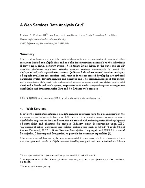
A Web Services Data Analysis Grid*William A. Watson III†‡, Ian Bird, Jie Chen, Bryan Hess, Andy Kowalski, Ying Chen Thomas Jefferson National Accelerator Facility12000 Jefferson Av, Newport News, VA 23606, USASummaryThe trend in large-scale scientific data analysis is to exploit compute, storage and other resources located at multiple sites, and to make those resources accessible to the scientist as if they were a single, coherent system. Web technologies driven by the huge and rapidly growing electronic commerce industry provide valuable components to speed the deployment of such sophisticated systems. Jefferson Lab, where several hundred terabytes of experimental data are acquired each year, is in the process of developing a web-based distributed system for data analysis and management. The essential aspects of this system are a distributed data grid (site independent access to experiment, simulation and model data) and a distributed batch system, augmented with various supervisory and management capabilities, and integrated using Java and XML-based web services.KEY WORDS: web services, XML, grid, data grid, meta-center, portal1. Web ServicesMost of the distributed activities in a data analysis enterprise have their counterparts in the e-commerce or business-to-business (b2b) world. One must discover resources, query capabilities, request services, and have some means of authenticating users for the purposes of authorizing and charging for services. Industry today is converging upon XML (eXtensible Markup Language) and related technologies such as SOAP (Simple Object Access Protocol), WSDL (Web Services Description Language), and UDDI (Universal Description, Discovery and Integration) to provide the necessary capabilities [1].The advantages of leveraging (where appropriate) this enormous industry investment are obvious: powerful tools, multiple vendors (healthy competition), and a trained workforce* Work supported by the Department of Energy, contract DE-AC05-84ER40150.† Correspondence to: William Watson, Jefferson Laboratory MS 16A, 12000 Jefferson Av, Newport News, VA 23606.‡ Email: Chip.Watson@.(reusable skill sets). One example of this type of reuse is in exploiting web browsers for graphical user interfaces. The browser is familiar, easy to use, and provides simple access to widely distributed resources and capabilities, ranging from simple views to applets, including audio and video streams, and even custom data streams (via plug-ins).Web services are very much like dynamic web pages in that they accept user-specified data as part of the query, and produce formatted output as the response. The main difference is that the input and output are expressed in XML (which focuses upon the data structure and content) instead of HTML (which focuses upon presentation). The self-describing nature of XML (nested tag name + value sets) facilitates interoperability across multiple languages, and across multiple releases of software packages. Fields (new tags) can be added with no impact on previous software.In a distributed data analysis environment, the essential infrastructure capabilities include: · Publish a data set, specifying global name and attributes· Locate a data set by global name or by data set attributes· Submit / monitor / control a batch job against aggregated resources· Move a data set to / from the compute resource, including to and from the desktop · Authenticate / authorize use of resources (security, quotas)· Track resource usage (accounting)· Monitor and control the aggregate system (system administration, user views)· (for some applications) Advance reservation of resourcesMost of these capabilities can be easily mapped onto calls to web services. These web services may be implemented in any language, with Java servlets being favored by Jefferson Lab (described below).It is helpful to characterize each of these capabilities based upon the style of the interaction and the bandwidth required, with most operations dividing into low data volume information and control services (request + response), and high volume data transport services (long-lived data flow).In the traditional web world, these two types of services have as analogs web pages (static or dynamic) retrieved via http, and file transfers via ftp. A similar split can be made to map a data analysis activity onto XML based information and control services (request + response), and a high bandwidth data transport mechanism such as a parallel ftp program, for example bbftp [2]. Other non-file-based high bandwidth I/O requirements could be met by application specific parallel streams, analogous to today’s various video and audio stream formats.The use of web services leads to a traditional three tier architecture, with the application or browser as the first tier. Web services, the second tier, are the integration point, providing access to a wide range of capabilities in a third tier, including databases, compute and file resources, and even entire grids implemented using such toolkits as Condor [3], Legion[4], Globus[5] (see Figure 1).As an example, in a simple grid portal, one uses a single web server (the portal) to gain access to a grid of resources “behind” the portal. We are proposing a flexible extension of this architecture in which there may be a large number of web servers, each providing access to local resources or even remote services, either by using remote site web services or by using a non-web grid protocol.All operations requiring privileges use X.509 certificate based authentication and secure sockets, as is already widely used for e-commerce. Certificates are currently issued by a simple certificate authority implemented as a java servlet plus OpenSSL scripts and username + password authentication. These certificates are then installed in the user’s web browser, and exported for use by other applications to achieve the goal of “single sign-on”. In the future, this prototype certificate authority will be replaced by a more robust solution to be provided by another DOE project. For web browsing, this certificate is used directly. For applications, a temporary certificate (currently 24 hours) is created as needed and used for authentication. Early versions of 3rd party file transfers supports credential forwarding of these temporary certificates.2. Implementation: Data Analysis RequirementsThe Thomas Jefferson National Accelerator Facility (Jefferson Lab) is a premier nuclear physics research laboratory engaged in probing the fundamental interactions of quarks andgluons inside the nucleus. The 5.7 GeV continuous electron beam accelerator provides a high quality tool for up to three experimental halls simultaneously. Experiments undertaken by a user community of over eight hundred scientists from roughly 150 institutions from around the world acquire as much as a terabyte of data per day, with data written to a 12000 slot StorageTek silo installation capable of holding a year’s worth of raw, processed, and simulation data.First pass data analysis (the most I/O intensive) takes place on a farm of 175 dual processor Linux machines. Java-based tools (JASMine and JOBS, described below) provide a productive user environment for file migration, disk space management, and batch job control at the laboratory. Subsequent stages of analysis take place either at the Lab or at university centers, with off-site analysis steadily increasing. The Lab is currently evolving towards a more distributed, web-based data analysis environment which will wrap the existing tools into web services, and add additional tools aimed at a distributed environment.Within a few years, the energy of the accelerator will be increased to 12 GeV, and a fourth experimental hall (Hall D) will be added to house experiments which will have ten times the data rate and analysis requirements of the current experiments. At that point, the laboratory will require a multi-tiered simulation and analysis model, integrating compute and storage resources situated at a number of large university partners, with raw and processed data flowing out from Jefferson Lab, and simulation and analysis results flowing into the lab.Theory calculations are also taking a multi-site approach – prototype clusters are currently located at Jefferson Lab and MIT for lattice QCD calculations. MIT has a cluster of 12 quad-processor alpha machines (ES40s), and will add a cluster of Intel machines in FY02. Jefferson Lab plans to have a cluster of 128 dual Xeons (1.7+ GHz) by mid FY02, doubling to 256 duals by the end of the year. Other university partners are planning additional smaller clusters for lattice QCD. As part of a 5 year long range national lattice computing plan, Jefferson Lab plans to upgrade the 0.5 teraflops capacity of this first cluster to 10 teraflops, with similar capacity systems being installed at Fermilab and Brookhaven, and smaller systems planned for a number of universities.For both experiment data analysis and theory calculations the distributed resources will be presented to the users as a single resource, managing data sets and providing interactive and batch capabilities in a domain specific meta-facility.3. The Lattice PortalWeb portals for science mimic their commercial counterparts by providing a convenient starting point for accessing a wide range of services. Jefferson Lab and its collaborators at MIT are in the process of developing a web portal for the Lattice Hadron Physics Collaboration. This portal will eventually provide access to Linux clusters, disk caches, and tertiary storage located at Jefferson Lab, MIT, and other universities. The Lattice Portal is being used as a prototype for a similar system to serve the needs of the larger Jefferson Labexperimental physics community, where FSU is taking a leading role in prototyping activities.The two main focuses of this portal effort are (1) a distributed batch system, and (2) a data grid. The MIT and JLab lattice clusters run the open source Portable Batch System (PBS) [6]. A web interface to this system [7][8] has been developed which replaces much of the functionality of the tcl/tk based gui included with openPBS. Users can view the state of batch queues and nodes without authentication, and can submit and manipulate jobs using X.509 certificate based authentication.The batch interface is implemented as Java servlets using the Apache web server and the associated Tomcat servlet engine [9]. One servlet periodically obtains the state of the PBS batch system, and makes that available to clients as an XML data structure. For web browsing, a second servlet applies a style sheet to this XML document to produce a nicely formatted web page, one frame within a multi-frame page of the Lattice Portal. Applications may also attach directly to the XML servlet to obtain the full system description (or any subset) or to submit a new job (supporting, in the future, wide area batch queues or meta-scheduling).Because XML is used to hold the system description, much of this portal software can be ported to an additional batch system simply by replacing the interface to PBS. Jefferson Lab’s JOBS [9] software provides an extensible interface to the LSF batch system. In the future, the portal software will be integrated with an upgraded version of JOBS, allowing support for either of these back end systems (PBS or LSF).The portal’s data management interface is similarly implemented as XML servlets plus servlets that apply style sheets to the XML structures for web browsing (Figure 2.).The replica catalog service tracks the current locations of all globally accessible data sets. The back end for this service is an SQL database, accessed via JDBC. The replica catalog is organized like a conventional file-system, with recursive directories, data sets, and links. From this service one can obtain directory listings, and the URL’s of hosts holding a particular data set. Recursive searching from a starting directory for a particular file is supported now, and more sophisticated searches are envisaged.A second service in the data grid (the grid node) acts as a front end to one or more disk caches and optionally to tertiary storage. One can request files to be staged into or out of tertiary storage, and can add new files to the cache. Pinning and un-pinning of files is also supported. For high bandwidth data set transfers, the grid node translates a global data set name into the URL of a file server capable of providing (or receiving) the specified file. Access will also be provided to a queued file transfer system that automatically updates the replica catalog.While the web services can be directly invoked, a client library is being developed to wrap the data grid services into a convenient form (including client-side caching of some results, a significant performance boost). Both applet and stand-alone applications are being developed above this library to provide easy-to-use interfaces for data management, while also testing the API and underlying system.The back end services ( JASMine [11] disk and silo management) used by the data web services are likewise written in Java. Using Java servlets and web services allowed a re-use of this existing infrastructure and corresponding Java skills. The following is a brief description of this java infrastructure that is being extended from the laboratory into the wide area web by means of the web services described above.4. Java Infrastructure4.1. JASMineJASMine is a distributed and modular mass storage system developed at Jefferson Lab to manage the data generated by the experimental physics program. Originally intended to manage the process of staging data to and from tape, it is now also being applied for user accessible disk pools, populated by user’s requests, and managed with automatic deletion policies.JASMine was designed using object-oriented software engineering and was written in Java. This language choice facilitated the creation of rapid prototypes, the creation of a component based architecture, and the ability to quickly port the software to new platforms.Java’s performance was never a bottleneck since disk subsystems, network connectivity, and tape drive bandwidth have always been the limiting factors with respect to performance. The added benefits of garbage collection, multithreading, and the JDBC layer for database connectivity have made Java an excellent choice.The central point of management in JASMine is a group of relational databases that store file-related meta-data and system configurations. MySQL is currently being used because of its speed and reliability; however, other SQL databases with JDBC drivers could be used.JASMine uses a hierarchy of objects to represent and organize the data stored on tape. A single logical instance of JASMine is called a store. Within a store there may be many storage groups. A storage group is a collection of other storage groups or volume sets. A volume set is a collection of one or more tape volumes. A volume represents a physical tape and contains a collection of bitfiles. A bitfile represents an actual file on tape as well as its meta-data. When a file is written to tape, the tape chosen comes from the volume set of the destination directory or the volume set of a parent directory. This allows for the grouping of similar data files onto a common set of tapes. It also provides an easy way to identify tape volumes that can be removed from the tape silo when the data files they contain are no longer required.JASMine is composed of many components that are replicated to avoid single points of failure: Request Manager handles all client requests, including status queries as well as requests for files. A Library Manager manages the tape. A Data Mover manages the movement of data to and from tape.Each Data Mover has a Dispatcher that searches the job queue for work, selecting a job based on resource requirements and availability. A Volume Manager tracks tape usage and availability, and assures that the Data Mover will not sit idle waiting for a tape in use by another Data Mover. A Drive Manager keeps track of tape drive usage and availability, and is responsible for verifying and unloading tapes.The Cache Manager keeps track of the files on the stage disks that are not yet flushed to tape and automatically removes unused files when additional disk space is needed to satisfy requests for files. This same Cache Manager component is also used to manage the user accessible cache disks for the Lattice Portal. For a site with multiple disk caches, the Cache Managers work collaboratively to satisfy requests for cached files, working essentially like a local version of the replica catalog, tracking where each file is stored on disk (Figure 3). The Cache Manager can organize disks into disk groups or pools. These disk groups allow experiments to be given a set amount of disk space for user disk cache – a simple quota system. Different disk groups can be assigned different management (deletion) policies. The management policy used most often is the least recently used policy. However, the policies are not hard coded, and additional management policies can be added by implementing the policy interface.The Jefferson Lab Offline Batch System (JOBS, or just “the JobServer”) is a generic user interface to one or more batch queuing systems. The JobServer provides a job submission API and a set of user commands for starting and monitoring jobs independent of the underlying system. The JobServer currently interfaces with Load Sharing Facility (LSF). Support for other batch queuing systems can be accomplished by creating a class that interfaces with the batch queuing system and implements the batch system interface of the JobServer.The JobServer has a defined set of keywords that users use to create a job command file. This command file is submitted to the JobServer, where it is parsed into one or more batch jobs. These batch jobs are then converted to the format required by the underlying batch system and submitted. The JobServer also provides a set of utilities to gather information on submitted jobs. These utilities simply interface to the tools or APIs of the batch system and return the results.Batch jobs that require input data files are started in such a way as to assure that the data is pre-staged to a set of dedicated cache disks before the job itself acquires a run slot and is started. With LSF, this is done by creating multiple jobs with dependencies. If an underlying batch system does not support job dependencies, the JobServer can pre-stage the data before submitting the job.5. Current Status and Future DevelopmentsThe development of the data analysis web services will proceed on two fronts: (1) extending the capabilities that are accessible via the web services, and (2) evolving the web services to use additional web technology.On the first front, the batch web services interface will be extended to include support for LSF through the JOBS interface described above, allowing the use of the automatic staging of data sets which JOBS provides (current web services support only PBS). For the data grid, policy based file migration will be added above a queued (third party) file transfer capability, using remote web services (web server to web server) to negotiate transfer protocols and target file daemon URL’s.On the second front, prototypes of these web services will be migrated to SOAP (current system uses bare XML). Investigations of WSDL and UDDI will focus on building more dynamic ensembles of web-based systems, moving towards the multi-site data analysis systems planned for the laboratory.6. Relationship to Other ProjectsThe web services approach being pursued by Jefferson Lab has some overlap with the grid projects in the Globus and Legion toolkits, Condor, and with the Unicore product [12]. Each seeks to present a set of distributed resources to client applications (and users) as a single integrated resource. The most significant difference between Jefferson Lab’s work and these other products is the use of web technologies to make the system open, robust and extensible. Like Unicore, the new software is developed almost entirely in Java, facilitating easy integration with the Lab’s existing infrastructure. However, the use of XML and HTTP as the primary application protocol makes the web services approach inherently multi-language and open, whereas Unicore uses a Java-only protocol. At this early stage, the new system does not cover as wide a range of capabilities (such as the graphical complex job creation tool in Unicore or the resource mapping flexibility in Condor-G), but is rapidly covering the functionality needed by the laboratory. In particular, details it contains capabilities considered essential by the laboratory and not yet present in some of the alternatives (for example, the Globus Replica Catalog does not yet have recursive directories, which are now planned for a future release). In cases where needed functionality can be better provided by one of these existing packages, the services of these systems can be easily wrapped into an appropriate web service. This possibility also points towards the use of web service interfaces as a way of tying together different grid systems. In that spirit, Jefferson Lab is collaborating with the Storage Resource Broker [13] team at SDSC to define common web service interfaces to data grids. SRB is likewise developing XML and web based interfaces to their very mature data management product. ACKNOWLEDGEMENTSPortions of the Lattice Portal software is being developed as part of Jefferson Lab’s work within the Particle Physics Data Grid Collaboratory [14], a part of the DOE’s Scientific Discovery Through Advanced Computing initiative.REFERENCES[1] For additional information on web services technologies, see (July 9, 2001)/TR/2000/REC-xml-20001006Extensible Markup Language (XML)1.0 (Second Edition) W3C Recommendation 6 October 2000;/TR/SOAP/Simple Object Access Protocol (SOAP) 1.1 W3C Note08 May 2000; /TR/wsdl Web Services Description Language(WSDL) 1.1 W3C Note, 15 March 2001; /[2] See http://doc.in2p3.fr/bbftp/ (July 9, 2001). bbftp was developed by Gilles Farrache(farrache@cc.in2p3.fr) from IN2P3 Computing Center, Villeurbanne (FRANCE) to support the BaBar high energy physics experiment.[3] Michael Litzkow, Miron Livny, and Matt Mutka, Condor - A Hunter of IdleWorkstations Proceedings of the 8th International Conference of Distributed Computing Systems, June, 1988; see also /condor/[4] Michael J. Lewis, Andrew Grimshaw. The Core Legion Object Model Proceedings ofthe Fifth IEEE International Symposium on High Performance Distributed Computing, August 1996.[5] I. Foster and C. Kesselman. Globus: A Metacomputing Infrastructure Toolkit.International Journal of Supercomputing Application s. 11(2):115-128, 1997[6] See: /. (July 9, 2001) The Portable Batch System (PBS) is aflexible batch queueing and workload management system originally developed by Veridian Systems for NASA.[7] See /. (July 9, 2001)[8] P. Dreher, MIT W. Akers, J. Chen, Y. Chen, C. Watson, Development of Web-basedTools for Use in Hardware Clusters Doing Lattice Physics Proceedings of the Lattice 2001 Conference, to be published (2002) Nuclear Physics B.[9] See /tomcat/ (July 9, 2001)[10] I Bird, R Chambers, M Davis, A Kowalski, S Philpott, D Rackley, R Whitney,Database Driven Scheduling for Batch Systems, Computing in High Energy Physics Conference 1997.[11] Building the Mass Storage System at Jefferson Lab Proceedings of the 18th IEEESymposium on Mass Storage Systems (2001).[12] See http://www.unicore.de/ (July 9, 2001)[13] See /DICE/SRB/[14] See /. (July 9, 2001)。

关于电视机来历的英语作文Title: The Evolution of Television: A Journey Through History。
Television, an invention that has become an indispensable part of our daily lives, has a rich and fascinating history that spans over a century. Its evolution from simple mechanical devices to sophisticated digital screens mirrors the advancements in technology and the changing preferences of society. In this essay, we will delve into the origins and development of television, tracing its journey from its inception to the modern age.The concept of television can be traced back to thelate 19th century when inventors and scientists began experimenting with the transmission of images over long distances. One of the pioneers in this field was Scottish engineer John Logie Baird, who is credited with demonstrating the first working television system in 1925. Baird's system used mechanical rotating disks to captureand display images, laying the groundwork for future advancements in the field.However, it was not until the 1930s that television began to gain widespread popularity, thanks to the development of electronic television systems. In 1936, the BBC commenced regular television broadcasts in the United Kingdom, marking the beginning of the television era. These early television sets were bulky and expensive, making them accessible only to a wealthy few. Nevertheless, they captured the imagination of the public and soon became a staple in households around the world.The years following World War II saw significant advancements in television technology, with theintroduction of color television and improvements inpicture quality. In 1954, RCA introduced the first mass-produced color television set, revolutionizing the way people experienced television. The 1960s and 1970s witnessed further innovations, including the introduction of remote controls, cable television, and satellite broadcasting, expanding the reach and capabilities oftelevision.The latter half of the 20th century saw the transition from analog to digital television, ushering in a new era of high-definition programming and interactive features.Digital television offered superior image and sound quality, as well as additional channels and services, making it the preferred choice for consumers. The proliferation of flat-screen LCD and plasma displays further transformed the television landscape, making large, high-definition screens more affordable and accessible to the masses.In recent years, the rise of internet streamingservices and smart TVs has revolutionized the way we consume television content. With platforms like Netflix, Hulu, and Amazon Prime Video, viewers have unprecedented access to a vast library of movies, TV shows, and original programming, anytime and anywhere. Smart TVs, equipped with internet connectivity and built-in streaming apps, have become the centerpiece of modern living rooms, offering a seamless and immersive entertainment experience.Looking ahead, the future of television promises even more exciting developments, with advancements in technology such as 8K resolution, virtual reality, and augmented reality poised to redefine the viewing experience once again. As television continues to evolve and adapt to the changing needs and preferences of consumers, one thing remains certain: its enduring appeal as a powerful medium for entertainment, information, and communication.In conclusion, the history of television is a testament to human ingenuity and innovation, from its humble beginnings as a mechanical curiosity to its current status as a ubiquitous presence in our lives. As we celebrate the achievements of the past and look forward to the possibilities of the future, let us never forget the transformative impact of this remarkable invention on society and culture.。

2020-2021学年哈尔滨市第九中学高三英语期中考试试卷及参考答案第一部分阅读(共两节,满分40分)第一节(共15小题;每小题2分,满分30分)阅读下列短文,从每题所给的A、B、C、D四个选项中选出最佳选项ANo one knows when the first printing press was invented or who invented it. but the oldest known printed text originated in China during the first millennium (千年) AD.The Diamond Sutra (《金刚经》), a Buddhist book from Dunhuang, China during the Tang Dynasty, is said to be the oldest known printed book.The Diamond Sutrawas created with a method known as block printing (雕版印刷), which used boards of hand-carved wood blocks in reverse.It was said that the moveable type was developed by Bi Sheng. He was fromYingshan,Hubei,China, living from 970 to 1051 AD. His method replaced panels of printing blocks with moveable individual Chinese characters that could be reused. The first moveable Chinese Characters were carved into clay and baked into hard blocks that were then arranged onto an iron frame that was pressed against an iron plate.The earliest mention of Bi Sheng’s printing press is in the bookDream Pool Essays, written in 1086 by Shen Kuo, who noted that his nephews came into possession of Bi Sheng’s typefaces (字体) after his death. Shen Kuo explained that Bi Sheng did not use wood because the texture is inconsistent (不一致的) and absorbs wetness too easily.By the time of the Southern Song Dynasty, which ruled from 1127 to 1279 AD, books had become popular in society and helped create a scholarly class of citizens who had the capabilities to become civil servants. Large printed book collections also became a status symbol for the wealthy class.1. When was Bi Sheng’s printing press first introduced in history?A. After Bi Sheng died and his nephews owned his typefaces.B. When books became popular in the Southern Song Dynasty.C. After the block printing was replaced by the moveable type printing.D. WhenThe Diamond Sutrawas printed into a book.2. What can we infer from the passage?A. Shen Kuo made great contributions to printing.B. The moveable type printing was invented earlier than block printing.C. Printed books were hard to get in the Song Dynasty.D. By the Southern Song Dynasty, books had helped people get to higher social positions.3. Why does the author write this passage?A. To show that Buddhism was popular in the Tang Dynasty.B. To introduce the early history of printing.C. To memorize Bi Sheng, developing the moveable type printing.D. To indicate the advantages of moveable type printing.BDengue is a very painful illness spread by mosquitoes. In severe cases, dengue can even be deadly. Dengue is a serious disease affecting people in around 120 countries. It can cause high fevers, headaches, and severe pain. It’s caused by a virus spread by bites from mosquitoes. Therefore, dengue is more common in warm areas. Every year, roughly 390 million people get dengue, and as many as 25,000 die from it.Now scientists seem to have found a way to protect humans from dengue by first protecting mosquitoes. Dengue fever is caused by a virus. Though it may seem strange to think of it this way, the mosquitoes that spread the dengue virus are also infected with it. But the virus doesn’t seem to hurt the mosquitoes.Wolbachia is a kind of bacteria commonly found in many insects. In some insects, Wolbachia can keep some viruses fromduplicatingthemselves, which is how viruses grow inside a body. Wolbachia isn’t naturally found in mosquitoes. But by infecting these mosquitoes with Wolbachia, scientists can keep the mosquitoes from catching the dengue virus. Even better, the young mosquitoes coming from the eggs of the infected mosquitoes also carry Wolbachia.Researchers working with the World Mosquito Program (WMP) ran a 27-month study in Yogyakarta, Indonesia. They split a 10-square-mile area up into 24 smaller areas. In half of the areas, the scientists did nothing. In the other half, they set out containers of eggs from mosquitoes that had Wolbachia. They did this every two weeks for just 4 to 6 months.Ten months later, 80% of the mosquitoes in the treated areas carried Wolbachia. The researchers report the number of dengue cases in the treated areas was reduced by 77% and that the number of people needing hospital care for dengue dropped by 86%.Because the results of the experiment were so good, the WHO has placed Wolbachia-infected mosquito eggs in all parts of Yogyakarta and surrounding areas. The WHO says that within a year, their efforts will protect 2.5 million people against dengue and that their efforts will be turned into a program that can be repeated worldwide.4. What kind of disease is dengue?A. It is likely to cause death.B. It causes no pain but fevers.C. It happens less often in hot areas.D. It hurts both people and mosquitoes.5. The underlined word “duplicating” in paragraph 3 most probably means “________”.A. worsening the harm ofB. expanding the size ofC. increasing forces ofD. making copies of6. What can be inferred about the method from the figures listed in paragraph 5?A. Its wide use.B. Its effectiveness.C. Its complexity.D.Its easy operation.7. What’s the WHO’s attitude towards the method?A. Ambiguous.B. Positive.C. Tolerant.D. Skeptical.CSummer heat can be dangerous, and heat leads to tragedy far toooften. According to kidsandcars, org, an average of 37 young children per year die of car heat in the US, when they are accidentally left in a hot vehicle.For Bishop Curry, a fifth grader from Mckinney, Texas, one such incident hit close to home. A six-month-old baby from his neighborhood died after hours in a hot car. After hearing about her death, Curry decided that something needed to be done. Young Curry, who turned 11 this year, has always had a knack for inventing things, and he drew up a sketch (草图) of a device he called “Oasis.”The device would attach to carseats and watch the temperature inside the car. If it reached a certain temperature in the car, and the device sensed a child in the carseat, it would begin to circulate cool air. Curry alsodesigns the device using GPS and Wi-Fi technology, which would alarm the child’s parents and, if there was no response from them, the police.Curry’s father believes that the invention has potential. “The cool thing about Bishop’s thinking is none of this technology is new,” he said. “We feel like the way he’s thinking and combining all these technologies will get to production faster.” His father even introduced the device to Toyota, where he works as an engineer. The company was so impressed that they sent Curry and his father to a car safety conference in Michigan.In January, Curry’s father launched a campaign for the invention. They hope to raise money to finalize the patent, build models, and find a manufacturer. Their goal was $20,000, but so many people believed in Oasis’ potential that they have raised more than twice that — over $46,000.Curry’s father remembers the first time he saw his son’s sketch. “I was so proud of him for thinking of a solution,” he said. “We always just complain about things and rarely offer solutions.”8. What inspired Curry to invent Oasis?A. His narrow escape from death after being locked in a car.B. His knowledge of many children’s death because of car heat.C. The death of his neighbor’s baby after being left in a hot car.D. The injury of 37 children in his school in a car accident.9. What would Oasis do if it was hot in a car with a child?A. It would inform the parents or even the police.B. It would pump out the hot air in the car.C. It would sound the alarm attached to the car.D. It would get the window open to save the child.10. What does Curry’s father think is cool about Curry’s invention?A. It used some of the most advanced technology.B. It simply combined technologies that existed.C. It could accelerate production of new technology.D. It is the most advanced among similar products.11. Why did Curry’s father start a campaign to raise money?A. To conduct experiments to test the invention.B. To get other children devoted to inventions.C. To support a charity of medical aid for children.D. To get the patent and bring it to production.DThereare two days that set you on your path in life: the day you’re born, and the day you realize why you were born.Growing up south of Chicago in Harvey, Illinois, most people just had their heads down trying to make it from point A to point B. I was the same way, just going with the flow. I played basketball in high school because I was good at it and because other people thought I should until I discovered my talent.I give up basketball and started doing speeches. It wasn’t a popular decision but my grandfather told me to do what made me happy. I fell in love with comedy and performing. And when I discovered the passion, I realized why I was born.I knew I had something to offer —I knew that not only am I powerful, but I can make a difference.I realized a long time ago that my dream is not to be famous or rich. My talent is to entertain. But it’s more than that. I have the chance to reach people, to brighten days, to bring laughter and positive energy into lives and inspire. And I am grateful forit.Acting putting myself out there and having doors closed on me time and time again has taught me a lot about myself. I have learned to trust what I have to offer the world over momentary doubt. I’ve learned to put my faith over my feelings. And I've grown a tough skin. More importantly, I have learned there is a long way towards our goals and that when we put our talents and passion to work, we determine our value.Like a lot of places across the country, there’s poverty, crime, violence and unemployment in Harvey. And growing up there, a lot of people have tragically low expectations for life. But I know that with the right opportunity and with help along the way, everyone can find their passion and go after it. My life is proof.12. What was the author born to do according to the text?A. Be a basketball player.B. Act and perform.C. Make speeches.D. Teach people.13. What does the underlined word “it” in Paragraph 5 refer to?A. Chance.B. Energy.C. Days.D. Laughter.14. What is the author’s purpose of writing this text?A. To help others find their talents.B. To prove his decision was right.C. To inspire people to follow their dreams.D. To encourage people to set a goal.15. What can be the best tile for the text?A. Success Lies in Hard Work.B. How to Achieve the Dream Is Important.C. The Two Important Days in Life.D. The Day I Realized What I Was Born to Do.第二节(共5小题;每小题2分,满分10分)阅读下面短文,从短文后的选项中选出可以填入空白处的最佳选项。

临床检验诊断学专业英语The Importance of Clinical Laboratory Diagnostics in Modern Medicine.In the ever-evolving landscape of modern medicine, clinical laboratory diagnostics play a pivotal role in ensuring accurate and timely patient care. This field,often referred to as clinical pathology or laboratory medicine, involves the examination of biological samples such as blood, urine, and tissue specimens to aid in the diagnosis, prevention, and treatment of diseases.The foundation of clinical laboratory diagnostics liesin the principles of biochemistry, hematology, microbiology, immunology, and molecular biology. These disciplinesprovide the framework for understanding the normal and abnormal functions of the human body at the cellular and molecular levels. By analyzing samples obtained from patients, clinicians can gain insights into the presence, type, and progression of diseases.One of the most significant applications of clinical laboratory diagnostics is in the field of personalized medicine. By examining genetic markers, molecular signatures, and other biomarkers, doctors can tailor treatment plans to the individual needs of patients. This approach has revolutionized healthcare, leading to improved outcomes and reduced side effects.Moreover, the advancement of technology hassignificantly transformed clinical laboratory diagnostics. Automation, robotics, and artificial intelligence have enabled laboratories to process and analyze larger volumes of samples with greater precision and efficiency. This technological boom has also led to the development of novel diagnostic tests and methods, further expanding the capabilities of clinical laboratories.However, the importance of clinical laboratory diagnostics extends beyond the laboratory itself. Effective communication between laboratorians and clinicians is crucial for ensuring accurate diagnosis and treatment.Laboratorians must provide clear and concise reports that are easy to understand, highlighting any abnormal findings and recommending appropriate follow-up actions.In addition, the ethical and regulatory framework governing clinical laboratory diagnostics is paramount. Laboratories must adhere to strict quality control measures to ensure the accuracy and reliability of their test results. They must also comply with privacy laws to protect the confidentiality of patient information.In conclusion, clinical laboratory diagnostics are integral to the provision of high-quality healthcare. They provide clinicians with critical information about the health status of their patients, enabling them to make informed decisions about diagnosis, treatment, and prevention. As medicine continues to evolve, so must the field of clinical laboratory diagnostics, embracing new technologies and approaches to better serve the needs of patients and the healthcare community at large.。

中国2021年度重要医学进展英文Important Medical Advancements in China in 2021In 2021, China made significant advancements in the field of medicine. These achievements have the potential to revolutionize the healthcare landscape not only in China but also globally. Below are some of the notable medical advancements made in China in 2021:1. COVID-19 Vaccines: China developed multiple COVID-19 vaccines, including Sinopharm, Sinovac, and CanSinoBIO. These vaccines have been widely distributed both domestically and internationally, leading to the successful containment and mitigation of the COVID-19 pandemic.2. Gene Therapy Breakthrough: Chinese scientists made groundbreaking progress in gene therapy, particularly in the treatment of genetic diseases. They successfully used CRISPR technology to cure a woman with β-thalassemia, a hereditary blood disorder. This achievement opened up new possibilities for treating genetic diseases effectively.3. Artificial Intelligence in Healthcare: China continued to lead in the integration of artificial intelligence (AI) in healthcare. AI technology has been used in diagnosing diseases, predicting patient outcomes, and drug discovery. China's advancements in AI have shown promising results in improving patient care and expanding the capabilities of the medical field.4. 5G-enabled Smart Hospitals: China introduced 5G technology inhospitals, enabling faster and more stable data transfer and communication. This development has revolutionized telemedicine, remote monitoring, and real-time healthcare services, especially in rural areas, where access to medical care is limited.5. Organ Transplantation Advances: China made significant progress in organ transplantation, increasing the number of successful organ transplants and improving the success rates. Improved techniques and protocols have enhanced patient outcomes and saved numerous lives.6. Precision Medicine: China accelerated its efforts in the field of precision medicine, aiming to tailor medical treatments to individual patients based on their genetic makeup, lifestyle, and environmental factors. Precision medicine has the potential to provide more targeted and effective therapies, minimizing side effects and improving patient outcomes.7. Traditional Chinese Medicine (TCM) Research: China continued its research and development in traditional Chinese medicine, exploring its potential in treating various diseases. Several studies have shown the effectiveness of TCM in improving symptoms and quality of life, especially for chronic conditions. These advancements collectively demonstrate China's commitment to pushing the boundaries of medical science and improving healthcare for its population and beyond. These breakthroughs will likely continue to have a lasting impact on the medical field in the years to come.。

人工智能体验中心英语作文Artificial Intelligence Experience Centre.In the heart of the bustling metropolis, a beacon of technological marvel stands tall—the Artificial Intelligence Experience Centre. This immersive sanctuary invites visitors into a realm where the boundaries of human ingenuity and machine intelligence blur. Step through its portals and embark on a journey that will redefine your perception of the future.Interactive Exhibits: A Symphony of Learning.Upon entering the hallowed halls of the centre, your senses are greeted by an array of interactive exhibits that ignite curiosity and inspire wonder. Engage with chatbots that possess uncanny conversational abilities, powered by sophisticated natural language processing algorithms. Marvel at facial recognition technology that reads emotions with unparalleled accuracy. Immerse yourself in virtualreality simulations that transport you to otherworldly realms.Each exhibit is a testament to the boundless potential of AI, showcasing its applications in diverse domains. From healthcare to transportation, education to entertainment, the centre demonstrates how AI is transforming our world in myriad ways.Demonstrations: Unveiling the Magic Behind the Machine.Complementing the interactive exhibits are live demonstrations that unveil the inner workings of AI algorithms. Witness firsthand how neural networks analyze vast datasets, identifying patterns and making predictions with astonishing accuracy. Observe how robots navigate complex environments, guided by advanced machine learning techniques.These demonstrations provide a glimpse into theintricate tapestry of AI, empowering visitors with a deeper understanding of its capabilities and limitations.Educational Programs: Igniting Passion for Innovation.Recognizing the transformative power of AI, the experience centre offers a comprehensive range of educational programs tailored to all ages and skill levels. Hands-on workshops introduce children to the fundamentals of AI through age-appropriate activities, fostering their interest in STEM fields.Specialized courses cater to industry professionals, providing them with the knowledge and skills required to harness AI's potential in their respective domains. The centre also hosts conferences and thought leadership events that bring together experts from academia, industry, and government to discuss the latest advancements and challenges in AI.Research and Innovation Hub: Pushing the Frontiers of AI.Beyond its educational and experiential offerings, theexperience centre serves as a hub for cutting-edge research and innovation in AI. Scientists and engineers collaborate within its walls, exploring uncharted territories and pushing the boundaries of human knowledge.State-of-the-art laboratories equipped with advanced computational resources enable researchers to develop and test novel AI algorithms, expanding the capabilities ofthis transformative technology. The centre's commitment to innovation ensures that visitors remain at the forefront of AI advancements, witnessing firsthand the genesis of groundbreaking ideas.A Catalyst for Societal Transformation.The Artificial Intelligence Experience Centre transcends its role as a technological showcase. It serves as a catalyst for societal transformation, fostering discussions on the ethical implications of AI and its impact on humanity.Through public forums and workshops, the centre engagesthe community in dialogue about the future of AI and the values that should guide its development and deployment. By promoting responsible and ethical AI practices, the centre empowers society to shape the trajectory of this transformative technology.A Gateway to the Future.As visitors depart from the Artificial Intelligence Experience Centre, they carry with them not only a deeper understanding of AI's capabilities, but also a profound sense of aspiration and optimism for the future. The centre serves as a gateway to a world where human ingenuity and machine intelligence intertwine, creating boundless possibilities and empowering humanity to address the challenges and seize the opportunities of the 21st century.。

DPI 610/615 Series is a Druck product. Druck has joined other GE high–technology sensing businesses under a new name–GE Industrial, Sensing.g•Ranges -14.7 to 10,000 psi•Accuracy 0.025% full scale (FS) all ranges •Integral combined pressure/vacuum pump •Dual readout: input and output•4 to 20 mA loop test: auto step and ramp •Intrinsically safe (IS) version•RS232 interface and fully documenting version •Remote pressure sensorsFeaturesDruck PortablePressure CalibratorsDPI 610/615 SeriesThe technically advanced Druck DPI 610 and DPI 615portable calibrators are the culmination of many years of field experience with the company’s DPI 600 series.These self-contained, battery powered packages contain a pressure generator, fine pressure control, device energizing (not IS version) and output measurement capabilities, as well as facilities for 4 to 20 mA loop testing and data storage. The rugged weatherproof design is styled such that the pressure pump can be operated and test leads connected withoutcompromising the visibility of the large dual parameter display. The mA step and ramp outputs and a built-in continuity tester extend the capabilities to include the commissioning and maintenance of control loops.Setting the Standard for PortablePressure CalibratorsA highly accurate and easy to use calibrator is only part of the solution for improving overall data quality and working efficiency. The DPI 610 and DPI 615, with data storage and RS232 interface, reduce calibration times and eliminate data recording errors. The DPI 615 also provides error analysis for field reporting of calibration errors and pass/fail status. In addition, procedures downloaded from a PC automatically configure theDPI 615 to pre-defined calibration and test routines. Improved performanceThe DPI 610/615 Series combine practical design with state-of-the-art performance, summarized as follows: Accuracy0.025% FS for ranges 1 to 10,000 psiRanges 1 psi to 10,000 psi including gauge, absolute anddifferential versionsIntegral Pneumatic–22 inHg to 300 psiPressure SourceIntegral Hydraulic0 to 6000 psiPressure SourceMeasure Pressure, mA, V, switch state (open/closed) andambient temperatureOutput: Pressure, mA step, mA ramp, mA value Energizing Supplies10 and 24 VDC (not IS version)Data Storage92 KbytesDocumenting (DPI 615 only)Error analysis with pass/fail status and graphs.two-way PC communication for transferringprocedures and resultsRemote pressure sensors Up to 10 digitally characterized sensors percalibratorSimplified OperationGE’s knowledge of customer needs, combined with innovative design, results in high performance,multi-functional calibrators which are simple to use. The key to simple operation is the Task Menu. Specific operating modes such as P-I, switch test and leak test are configured at the touch of a button by menu selection.Featuring highly reliable pneumatic and hydraulic assemblies and self-test routines, the DPI 610/615 Series can be relied upon time and time again for field calibration in the most extreme conditions.The DPI 610 and DPI 615 have been designed for ease of use while meeting a wide range of application needs including calibration, maintenance and commissioning. The Intrinsically Safe versions, certified to European and North American standards for use in hazardous areas,reduce response times to breakdowns and emergencies by removing the need for ’Hot Permits‘ and gas detection equipment. This gives peace of mind to all those responsible for safety within hazardous areas.The dual parameter display shows the Input and Output values in large clear digits. A unique built-in handle provides a secure grip for on-site use in addition to a shoulder strap which is also designed to allow the instrument to be suspended for hands-free operation.Any technician can use these calibrators without formal training, such as a novice on an emergency call out, or those familiar with the DPI 601. By selecting basic mode the calibrator is configured to source pressure and measure mA or V, with all non-essential keys disabled.Dedicated Task MenuThe dedicated task key gives direct access to the task menu. Select the required test, for example P-I for a pressure transmitter, and with a single key press, the calibrator is ready.Use the advanced mode for custom tasks and add to the user task menu for future use.Some of the CapabilitiesP mA V10 V*24 V*Switch°FMeasure __Source _ __P = PressureF = Local ambient temperature* = Not ISPressure Transmitter CalibrationThe P-I task configures the DPI 610/615 Series to simultaneously display the output pressure and the input current. The pressure unit can be chosen to suit the transmitter and a 24 V supply is available forloop-power (not IS version).For process transmitters reading in percentage use % span to scale the pressure accordingly.The DPI 610/615 Series pneumatic calibrator hand-pump can generate pressure from -12 to 300 psi. The volume adjuster gives fine pressure setting and the release valve also allows gradual venting for falling calibration points.Reduce the burden imposed by quality systems such as ISO 9000, simply store results in memory and leave bothpen and calibration sheet back at the office. Pressure Switch Testing and LeakTestingFor switch set-up and fault finding, the display shows the output pressure and switch state open or closed. Continuity is declared by an audible signal.Verify pressure switch performance using the automatic procedure. The DPI 610/615 Series displays the switch points and the contact hysteresis.Leak test will check for pressure leaks prior to calibration or during routine maintenance. Define the test times or use the defaults and wait… The DPI 610/615 Series will report the start and stop pressures, the pressure change and the leak rate.Take a ‘snapshot’ of the working display, all details are stored in a numbered location for later recall.Loop Testing and Fault FindingThe DPI 610/615 Series can generate a continuous mA step or mA ramp output, allowing a single technician to commission control loops.Feed the loop using mA step or mA ramp and at the control room, check the instrumentation.Use mA value E for alarm and trip circuit tests. Any mA output can be set and adjusted from the keypad.Comprehensive process features aid flow and level measurement and help with trouble shooting. Select tare, maximum/minimum, filter, flow or %span and the function will be applied to the input parameter.Save time fault finding, by leaving the DPI 610/615 Series to monitor system parameters. Use periodic data log or the maximum/minimum process function to captureintermittent events.Remote Pressure SensorsBy adding up to ten external sensors (one at a time) the working ranges of the DPI 610 and DPI 615 can be extended. Modules from 1 inH2O to 10,000 psi are available to suit most applications.As a leading manufacturer of pressure sensors GE has applied the latest silicon technology and digital compensation techniques to develop these sensors.Remote sensors offer a cost-effective means of expanding the capabilities of the DPI 610 and DPI 615, for example in the following applications:•Low pressure•Pressure-to-pressure•Differential pressure•Wide range, high-accuracy•Test-point monitoring•To prevent cross contamination•To configure pneumatic calibrators for high pressure hydraulic systems•To configure hydraulic calibrators for low pressurepneumatic systemsDPI 615 Portable Documenting Pressure CalibratorThe DPI 615 adds powerful time saving and error eliminating features to the comprehensive functionality of the DPI 610. These include field error calculations with PASS/FAIL analysis and two way PC communications for downloading procedures and uploading results. Reporting Errors in the FieldThe DPI 615 calculates errors and reports the pass/fail status during field tests. Problems and failures can be analyzed graphically for immediate assessment and correction. This simple to use feature reduces calibration and maintenance times and eliminates human pleting the Paper TrailIt takes longer to fill out a calibration report, calculate the errors and assess the results than it does to calibrate the transmitter. With the DPI 615, documents can be quickly completed either on site or, at a more convenient time and location, by recalling the information from theDPI 615’s memory.Calibration Management SystemsWhen used in conjunction with calibration management software the DPI 615 greatly reduces the financial and resource burden imposed by quality systems such as ISO 9000. As work orders are issued, object lists and procedures are downloaded to the DPI 615. In the field these procedures configure the instrument for the tests. The errors and pass/fail status are reported and recorded in memory (as found or as left results) for later upload to the software. Calibration certificates can then be printed and plant maintenance systems updated. The whole documenting process is completed in a fraction of the time it takes using manual systems and without human error.For information on Intecal calibration software please visit . The DPI 615 is also compatiblewith many third party software systems.DPI 610/615PC Pneumatic CalibratorHand-Pump-22 inHg to 300 psi capability Volume AdjusterFine pressure adjustment Release ValveVent and controlled release Pressure Port 1/8 NPT female MediaMost common gasesDPI 610/615LP Low Pressure CalibratorVolume AdjusterDual piston for coarse/fine pressure setting Release ValveVent and controlled release Pressure Ports 1/8 NPT female MediaNo corrosive gasesPlease refer to DPI 610/615 LP Series datasheet for full specification.DPI 610/615SpecificationsDPI 610/615HC Hydraulic CalibratorPriming PumpFeeds from external source Shut-off ValveOpen for system priming Screw Press0 to 6000 psi capability Pressure Port 1/8 NPT femaleMediaDimineralized water and most hydraulic oilsDPI 610/615I IndicatorRelease ValveVent and controlled release Pressure Port 1/8 NPT femaleMediaMost common fluids compatible with stainless steelPressure RangesThe DPI 610/615 PC, HC,LP and I include an integral sensor, the range of which should be specified from the list below. Up to 10 remote sensors (option B1) may also be ordered per calibrator.Span Shift0.5%/500 psi of line pressure for differential ranges.Temperature Effects±0.002% reading/°F averaged over –15°F to 105°F and w.r.t. 68°F.Remote Sensor MediaStainless steel and hastelloy compatibility.Negative Differential: Stainless steel and quartz compatibility.Overpressure Safe to 2 x FSexcept (1) 500 psi maximum, (2) 9000 psi maximum,(3) 5000 psi maximum(1), (2) and (3) refer to pressure range tablePressure Pneumatic HydraulicIndicator Remote Accuracy Range DPI 610PC/DPI 610HC/DPI 610I/Option % FS DPI 615PCDPI 615HC DPI 615I (B1)1 psi (-1) G —G G or D 0.0052.5 psi (-2.5) G —G G or D 0.0255 psi (-5) G or A —G or A G, A or D 0.02510 psi (-10) G or A —G or A G, A or D 0.02515 psi (-15) G or A —G or A G, A or D 0.02530 psi (-15) G or A —G or A G, A or D 0.02550 psi (-15) G or A —G or A G, A or D 0.025100 psi (-15) G or A —G or A G, A or D 0.025150 psi (-15) G or A —G or A G, A or D 0.025300 psi (-15) G orA (1)—G or A G, A or D 0.025500 psi (-15) ——G or A G,A or D 0.0251000 psi (-15) ——G or A G or A 0.0251500 psi ——SG or A SG or A 0.0252000 psi ——SG or A SG or A 0.0253000 psi —SG or A SG or A SG or A 0.0255000 psi —SG or A SG or A (3)SG or A 0.0256000 psi —SG or A (2)——0.02510000 psi ———SG or A0.025•Values in ( ) indicate negative calibration for gauge and differential ranges•A = Absolute, D = Differential (500 psi) line pressure, G = Gauge, SG = Sealed Gauge •(1), (2) and (3) refer to over pressure.•Accuracy is defined as non-linearity, hysteresis and repeatabilitySpecial FeaturesPressure Units25 scale units plus one user-defined mA stepContinuous cycle at 10 sec intervalsmA rampContinuous cycle with configurable end values and 60 second travel timeData logMulti-parameter with internal memory for 10,000 values.Variable sample period or log on key pressElectrical InputsInput Range AccuracyResolution RemarksVoltage*±50 VDC±0.05% reading 100 :V Autoranging, > ±0.004% FSmaximum10 M S±30 VDC(IS version)Current*±55 mA±0.05% reading 0.001 mA10 S , 50 V ±0.004% FSmaximum(30 V maximum IS version)Temperature 15°F to 105°F ±2°F 0.2°FLocal ambient SwitchOpen/closed ____5 mA whetting*Temperature coefficient ±0.004% reading/°F wrt 68°FElectrical OutputsOutput Range Accuracy ResolutionRemarks Voltage 10 VDC±0.1%__Maximum (Not IS load 10 mA version)24 VDC ±5%__Maximum load 26 mACurrent*0 to 24 mA±0.05% reading 0.001 mA__±0.1% FS*Temperature coefficient ±0.004% reading/°F wrt 68°FFor IS version Ui = 30 V maximum, Ii = 100 mA maximum, Pi = 1 W maximum and Uo = 7.9 V maximum.ElectricalFunctionmA Output4 to 20 mA linear 48121620____0 to 20 mA linear 05101520____4 to 20 mA flow 4581320____0 to 20 mA flow 0 1.25511.2520____4 to 20 mA valve3.844.212192021Power supply•Six 1.5 V 'C' cells, alkaline (up to 65 hours nominal use at 68°F. Rechargeable battery pack and charger are supplied as standard (20 hours nominal use)•Rechargeable batteries and charger/power supply not available for the IS version which uses alkaline batteries only.Options(A)Rechargeable Batteries and ChargerRechargeable battery pack (P/N 191-A022) and 110 VAC charger/power supply (P/N 191-A023). A 220 VAC charger/power supply is also available (P/N 191-129). (Not available for IS version)(B1)Remote Pressure SensorThe DPI 610/615 have a second pressure channel which can be configured with up to 10 remote sensors (one at a time). For ease of use the sensors are fitted with an electrical connector and 1/4 NPT female pressure port.Please refer to specifications for ranges and associated accuracy.At least one mating cable is required per DPI 610 when ordering remote pressure sensors _see Option (B2).(B2)Mating Cable for Remote SensorsA 6 ft mating cable for connecting remote sensors to the calibrator. At least one cable should be ordered when ordering Option (B1).(B3)Calibration of Special Remote Pressure Sensor(150 mV maximum) (Not available on IS version)(C)1/8 NPT Female AdaptorA stainless steel adaptor and bonded seal toconvert the standard G 1/8 female pressure port to 1/8 NPT female.(D1)Intecal for Industry (P/N Intecal-Ind)Developed to meet the growing demand on industry to comply with quality systems and calibration documentation. Test procedures are created in a Windows ®based application and devices into work orders for transfer to the DPI 325, DPI 335, DPI 605, DPI 615, TRX II and MCX II. Calibration results, are uploaded to the PC for analysis and to print calibration certificates.SnapshotPaperless notepad. Stores up to 20 complete displays Computer interface RS232Process functionsTare, maximum/minimum, filter, flow, % spanLanguageEnglish, French, German, Italian, Portuguese and Spanish Power managementAuto power off, auto backlight off, battery low indicator and status on key pressDisplayPanel2.36 in to 2.36 in graphic LCD with backlight. (Backlight not available on IS version)Readout± 99999 capability, two readings per secondEnvironmentalTemperature•Operating: 15°F to 120°F •Calibrated: 15°F to 105°F Humidity0 to 90%, non-condensing SealingGenerally to Type 12/IP54ConformityEN61010, EN50081-1, EN50082-1, CE marked Intrinsically safe version: Supplied certified for use in hazardous areasEEx ia IIC T4 certificate 2000.1003130To CAN/CSA-E79-11-95 and CAN/CSA E79-0-95 (Class 1,Division I, Groups A,B,C&D)PhysicalWeight: 6.6 lb, size: 11.8 in x 6.7 in x 5.5 ing©2006 GE. All rights reserved.920-107AAll specifications are subject to change for product improvement without notice.GE ®is a registered trademark of General Electric Co. Windows ®is a registered trademark of Microsoft Corporation, which is not affiliated with GE, in the U.S. and other countries. Other company or product names mentioned in this document may be trademarks or registered trademarks of their respective companies, which are not affiliated with GE.(D2)Intecal Calibration Management Software(P/N 7000-Intecal)Builds on the concept of Intecal for industry supporting both portable calibrators and on-line workshop instruments. Intecal is a simple-to-use calibration management software, which enables a high productivity of scheduling, calibration and documentation.Visit for more information and free download.(E1)Dirt/Moisture TrapWhere a clean/dry pressure media cannot beguaranteed the IDT 600 dirt/moisture trap prevents contamination of the DPI 610/615 pneumatic system and eliminates cross-contamination from one device under test to another.AccessoriesThe DPI 610 is supplied with carrying case, test leads,user guide and calibration certificate with data, asstandard. The DPI 610HC also has a 8 oz polypropylene fluid container and priming tube. (Alkaline batteries supplied for the IS version).Calibration StandardsInstruments manufactured by Druck are calibrated against precision equipment traceable to the National Institute of Standards and Technology (NIST).Related Products•Portable field calibrators•Laboratory and workshop instruments •Pressure transducers and transmittersOrdering InformationStandard complete packages are available for ranges 5,30, 100 and 300 psig. These include user guide, test leads, pressure/vacuum pump, volume adjuster, release valve, carrying case, rechargeable battery pack and charger. When ordering, please state type, pressure range and “complete”, e.g. DPI 610 PC, range 30 psig complete.For other ranges please state the following (where applicable):1.DPI 610 type number i.e. DPI 610 PC. For IS version use the suffix 'S' after the basic model number, e.g. DPI 610S PC or DPI 610S I. (Intrinsically safe hydraulic version not available)2.Built-in pressure range; gauge or absolute.3.Options, including range for remote sensors.Options B1 and D should be ordered as separate line items .。

3d打印英语术语3D printing, also known as additive manufacturing, has revolutionized the way products are designed and produced. This technology allows for the creation of complex and customized objects by building up layers of material to form a three-dimensional shape. As 3D printing has become more widespread, a set of specific terms and vocabulary has emerged to describe the various processes, materials, and tools used in this field. In this article, we will explore some common 3D printing English terms and their meanings.1. Additive Manufacturing: This is another term for 3D printing, as it refers to the process of adding material layer by layer to build up a 3D object.2. Filament: The material used in Fused Deposition Modeling (FDM) printers, typically made of thermoplastics such as ABS or PLA.3. Slicing Software: This software takes a 3D model and slices it into layers that the 3D printer can then build up one by one.4. Build Plate: The surface on which the 3D object is built. It may be heated to help with adhesion of the printed material.5. Nozzle: The part of the 3D printer that extrudes the material onto the build plate. It heats up the material to make it melt and then deposits it in thin layers.6. Resolution: Refers to the level of detail that can be achieved in a 3D printed object. Higher resolution means finer details can be reproduced.7. Support Structures: These are temporary structures added to a 3D model to provide support for overhanging or complex geometries during the printing process.8. Infill: The internal structure of a 3D printed object, which can be adjusted to make the object more or less dense.9. Extruder: The component of a 3D printer that pushes the filament through the nozzle to create the final object.10. Bed Leveling: The process of adjusting the build plate to ensure that it is level and at the right distance from the nozzle for proper printing.11. Stereolithography (SLA): A type of 3D printing technology that uses a liquid resin that is solidified by a laser to create a 3D object.12. Binder Jetting: A 3D printing process that uses a liquid binder to selectively bind powder particles together to create an object layer by layer.13. Selective Laser Sintering (SLS): A 3D printing process that uses a laser to sinter powdered material, typically metal or plastic, to create a solid object.14. Direct Metal Laser Sintering (DMLS): Similar to SLS, but specifically used for metal 3D printing by sintering metal powder with a laser.15. Heated Chamber: Some 3D printers have a heated chamber to maintain a stable temperature during printing, especially for materials that require high temperatures.16. Overhang: An area of a 3D model that extends beyond the previous layer, requiring support structures to prevent drooping or collapsing during printing.17. Print Speed: The speed at which the 3D printer moves and deposits material to create the final object. Faster speeds can reduce printing time but may sacrifice quality.18. Ultimaker: A popular brand of 3D printers known for their high-quality construction and reliable performance.19. Build Volume: The maximum size of the object that can be printed in a single job on a 3D printer, typically measured in cubic millimeters.20. Dual Extrusion: A feature that allows a 3D printer to use two different materials or colors in the same print job, expanding the possibilities for creating complex objects.These are just a few of the many terms used in the world of 3D printing. As technology continues to advance, new techniques and materials will undoubtedly emerge, expanding the capabilities of this exciting field. Whether you are a hobbyist, designer, engineer, or manufacturer, understanding these terms will help you navigate the world of 3D printing and unlock its full potential.。

英语作文自己发明的东西Here is an English essay about an invention of my own, with the content exceeding 1000 words as requested. The title is not included in the word count.I have always been fascinated by the world of innovation and technology. From a young age, I have been constantly dreaming up new ideas and concepts, imagining how I could create something that would make a difference in people's lives. It is this innate curiosity and drive to problem-solve that has led me to develop my own invention, one that I believe has the potential to revolutionize a particular industry.The inspiration for my invention came from a personal experience I had a few years ago. I was traveling abroad and found myself in a remote village with limited access to essential resources. As I navigated the challenges of daily life in this unfamiliar environment, I couldn't help but notice the significant disparities in access to basic necessities that many people in the developing world face on a regular basis. This experience truly opened my eyes to the pressing need for innovative solutions that could address these global inequities.After returning home, I began to meticulously research and brainstorm ideas that could potentially alleviate some of the problems I had witnessed. I spent countless hours poring over academic papers, industry reports, and expert interviews, trying to identify a specific area where my skills and expertise could make a meaningful impact. It was during this extensive research phase that the concept for my invention began to take shape.The core of my invention is a portable, self-sustaining water purification system that can be easily deployed in remote or resource-constrained regions. The system utilizes a combination of cutting-edge filtration technologies and renewable energy sources to provide clean, safe drinking water to communities in need. Unlike traditional water purification methods that often rely on centralized infrastructure and constant access to electricity, my invention is designed to be highly versatile and adaptable to a wide range of environmental conditions.At the heart of the system is a compact, lightweight filtration unit that can remove a vast array of contaminants, including bacteria, viruses, heavy metals, and even harmful chemicals. This filtration unit is powered by a integrated solar panel and battery system, ensuring that the device can operate independently of traditional power sources. The system also features a built-in water storage tank,allowing it to provide a continuous supply of clean water even in areas with limited access to surface water or groundwater.One of the key innovations of my invention is its modular design, which allows for easy customization and scalability. The filtration unit, solar panel, and water storage components can be easily assembled and configured to meet the specific needs of a given community or region. This modularity not only simplifies the installation process but also enables the system to be easily maintained and repaired by local users, reducing the need for specialized technical support.To further enhance the accessibility and affordability of my invention, I have designed it to be manufactured using readily available, low-cost materials. By leveraging local supply chains and production capabilities, I aim to ensure that the system can be produced and distributed at a price point that is within reach of the communities that need it most.In addition to its practical applications, my invention also incorporates a robust educational component. The system is accompanied by a comprehensive user manual and training materials, empowering local communities to understand the technology, maintain the system, and ultimately take ownership of their water security. This educational aspect is crucial in fostering long-term sustainability and ensuring that the benefits of the inventioncontinue to be realized long after its initial deployment.As I continue to refine and develop my invention, I have also been actively seeking partnerships with non-governmental organizations, government agencies, and private sector entities that share my vision of improving access to clean water globally. These collaborations have not only provided valuable feedback and resources but have also opened up new avenues for testing, deployment, and scaling of the technology.One such partnership has been with a leading international development organization that has expressed interest in piloting my invention in several remote communities in sub-Saharan Africa. Through this collaboration, we have been able to gather valuable data on the real-world performance and impact of the system, as well as refine the design based on user feedback and local environmental conditions.As I look to the future, I am filled with a sense of optimism and determination. I believe that my invention has the potential to make a tangible difference in the lives of millions of people around the world who currently lack access to clean, safe drinking water. By continuing to innovate, collaborate, and advocate for this technology, I am confident that we can work towards a future where clean water is a basic human right, rather than a privilege.Of course, the journey of bringing an invention to life is not without its challenges. I have faced numerous setbacks and obstacles along the way, from securing funding and navigating complex regulatory environments to overcoming technical hurdles and garnering buy-in from skeptical stakeholders. However, I have remained steadfast in my commitment, driven by the knowledge that the impact of my invention could be truly transformative.As I reflect on the process of developing my invention, I am struck by the immense power of human ingenuity and the ability of individuals to create solutions that can positively shape the world around them. This experience has reinforced my belief that innovation, when coupled with a deep understanding of societal needs and a genuine desire to make a difference, can be a powerful force for good.Moving forward, I am excited to continue refining and expanding the capabilities of my invention, exploring new applications and partnerships that can further amplify its impact. I am also committed to sharing my story and inspiring others, particularly young aspiring inventors and engineers, to pursue their own dreams of creating transformative technologies that can improve the human condition.In conclusion, the development of my invention has been a deeply rewarding and humbling journey. It has challenged me to thinkcreatively, to problem-solve in the face of adversity, and to relentlessly pursue a vision that I believe can make a tangible difference in the world. As I look ahead, I am filled with a sense of purpose and a deep conviction that the power of innovation can indeed change lives, one community at a time.。
电力电子英文作文Electric power electronics is a fascinating field that deals with the conversion and control of electrical power. It involves the use of electronic devices to convert and control the flow of electrical energy, which is essentialin various applications such as power supplies, renewable energy systems, electric vehicles, and industrial automation.One of the key components in power electronics is the power semiconductor devices, such as diodes, transistors, and thyristors. These devices are used to switch, regulate, and control the flow of electrical energy in different electronic circuits. They play a crucial role in the efficiency and performance of power electronic systems.Power electronic systems are widely used in modern society, from everyday appliances like refrigerators andair conditioners to industrial equipment and renewable energy systems. They are essential for converting andcontrolling electrical power to meet the diverse needs of different applications.The development of power electronics has led to significant advancements in energy efficiency and renewable energy integration. It has enabled the efficient conversion of electrical power from renewable sources such as solar and wind, making them more viable alternatives totraditional fossil fuels.The future of power electronics looks promising, with ongoing research and development aimed at improving efficiency, reducing costs, and expanding the capabilities of power electronic systems. As technology continues to evolve, power electronics will play an increasingly important role in shaping the future of energy management and sustainability.。
zemax软件学习计划IntroductionZemax is a powerful software tool used in the field of optics and photonics for designing and analyzing optical systems. With its comprehensive capabilities, Zemax helps in optimizing the performance of optical systems and allows for efficient simulation and analysis. This learning plan is designed to provide a structured approach to mastering Zemax, covering its various functionalities and applications. By following this plan, individuals can develop a strong foundation in using Zemax for optical system design and simulation.Learning ObjectivesThe primary objectives of this Zemax Software Learning Plan are as follows:1. Understand the fundamentals of Zemax software2. Learn about optical system design and analysis using Zemax3. Gain proficiency in using Zemax for simulation and optimization4. Explore advanced features and applications of Zemax5. Develop practical skills through hands-on exercises and projectsLearning Plan OverviewThe learning plan will be divided into several key modules, each covering specific aspects of Zemax software. The modules are designed to progressively build upon the foundational knowledge and skills required to effectively use Zemax for optical system design and analysis. It is important to note that the learning plan will involve a combination of theoretical learning, practical exercises, and real-world applications to ensure comprehensive understanding and skill development.Module 1: Introduction to ZemaxThis module will provide a comprehensive introduction to Zemax, covering its features, interface, and basic functionalities. Topics to be covered include:- Overview of Zemax software and its applications in optics- Understanding the user interface and workspace in Zemax- Introduction to Zemax terminology and workflow- Basic tools and operations in Zemax for creating optical systemsModule 2: Optical System Design FundamentalsThis module will focus on the fundamentals of optical system design and how Zemax facilitates the process. Key topics to be covered include:- Principles of optical system design and components- Creating and configuring optical components in Zemax- Optical properties and material selection in Zemax- System layout and configuration in ZemaxModule 3: Analysis and Simulation in ZemaxIn this module, participants will learn about the analysis and simulation capabilities of Zemax. Key topics include:- Performing ray tracing and optical analysis in Zemax- Understanding wavefront analysis and aberrations- Optimization techniques and tools in Zemax- Generating performance reports and data analysis in ZemaxModule 4: Advanced Features of ZemaxThis module will delve into advanced features and functionalities of Zemax, expanding on the capabilities of the software. Topics to be covered will include:- Advanced optical modeling and design considerations- Non-sequential ray tracing and its applications- Customization and scripting in Zemax- Integration of Zemax with other optical design tools and softwareModule 5: Practical Applications and ProjectsThe final module of the learning plan will focus on real-world applications of Zemax through practical projects and case studies. Participants will work on designing and analyzing optical systems and components using Zemax, integrating all the knowledge and skills gained throughout the learning plan.ConclusionThis Zemax Software Learning Plan is designed to provide a structured and comprehensive approach to mastering the capabilities of Zemax for optical system design and analysis. By successfully completing this learning plan, individuals can gain the knowledge and skills required to effectively utilize Zemax in their professional work, whether in academicresearch, industry, or any other field related to optics and photonics. Through theoretical learning, practical exercises, and real-world applications, participants can develop a strong proficiency in Zemax and its applications.References:- Zemax User Guide and Tutorials- Optical System Design Using Zemax: a Practical Guide (Book)- Online resources and tutorials provided by Zemax companyThis learning plan is intended to serve as a guide for individuals and institutions interested in developing expertise in Zemax software. It can be adapted and customized according to specific learning needs and objectives. With a structured approach to learning, individuals can maximize the potential of Zemax for optical system design and analysis, contributing to advancements in the field of optics and photonics.。
天和核心舱英语作文Title: The Tianhe Core Module: A Gateway to China's Space Ambitions。
China's ambitious space program has reached a significant milestone with the launch of the Tianhe Core Module, a crucial component of the country's space station. This module serves as the foundation for China's long-term presence in space and marks a new chapter in its space exploration endeavors.The Tianhe Core Module, also known as Harmony of the Heavens, was launched on April 29, 2021, aboard a Long March 5B rocket from the Wenchang Spacecraft Launch Site. It represents the first piece of the Chinese Space Station (CSS), which China aims to complete and make fully operational by 2022. This module serves as the living quarters for astronauts, providing them with living space, life support systems, and control centers for the entire station.One of the key features of the Tianhe module is its ability to support three astronauts for extended periods, showcasing China's capability to sustain human presence in space independently. The module's living quarters include sleeping areas, exercise equipment, and sanitary facilities, ensuring the well-being and productivity of astronauts during their missions.Moreover, the Tianhe Core Module serves as the central hub of the CSS, connecting other modules, laboratories, and cargo spacecraft. Its docking ports allow for additional modules to be attached, expanding the capabilities and functionalities of the space station over time. Thismodular approach enables China to adapt and upgrade the CSS according to future needs and technological advancements.In addition to providing a platform for scientific research and technological experiments, the Tianhe module plays a crucial role in international cooperation in space exploration. China has expressed its willingness to collaborate with other countries and internationalorganizations, offering opportunities for joint research projects and astronaut exchanges aboard the CSS.Furthermore, the successful launch and operation of the Tianhe Core Module demonstrate China's growing expertise in space technology and its commitment to peaceful exploration of outer space. As a major spacefaring nation, China's achievements in space contribute to the global efforts in understanding the universe, advancing scientific knowledge, and fostering international cooperation.Looking ahead, the Tianhe Core Module sets the stagefor China's ambitious plans for space exploration,including lunar missions, Mars exploration, and beyond. It symbolizes China's determination to become a leading player in space exploration and underscores the country's long-term vision for the peaceful use of outer space.In conclusion, the Tianhe Core Module represents a significant achievement for China's space program, laying the groundwork for the country's future endeavors in space exploration. As a key component of the Chinese SpaceStation, the module showcases China's technological capabilities, commitment to international cooperation, and vision for the peaceful exploration of outer space. With the successful launch of the Tianhe module, China embarks on a new era of space exploration, shaping the future of humanity's presence beyond Earth.。
人机对话的流程初中英语The development of artificial intelligence and natural language processing has enabled the creation of human-machine dialogue systems that can engage in meaningful conversations. These systems, often referred to as chatbots or virtual assistants, are designed to understand and respond to natural language inputs, allowing users to interact with them in a conversational manner. The process of human-machine dialogue in intermediate English involves several key steps, including input processing, intent recognition, response generation, and output delivery.The first step in the human-machine dialogue process is input processing. When a user provides a spoken or written input, the system must first convert the raw data into a format that can be analyzed and understood. For speech-based systems, this typically involves speech recognition, where the audio input is converted into text. For text-based systems, the input is simply the written text provided by the user.Once the input has been processed, the system must then recognizethe intent behind the user's message. This involves analyzing the semantic and contextual meaning of the input to determine the user's goal or desired action. This can be a complex task, as natural language can be ambiguous and context-dependent. Advanced natural language processing techniques, such as named entity recognition, sentiment analysis, and intent classification, are often employed to accurately identify the user's intent.After the intent has been recognized, the system must then generate an appropriate response. This response generation process involves several steps, including retrieving relevant information from knowledge bases or databases, applying natural language generation techniques to formulate a coherent and contextually relevant response, and ensuring that the response adheres to the user's language proficiency level (in this case, intermediate English).One of the key challenges in human-machine dialogue for intermediate English is ensuring that the language used in the system's responses is appropriate for the user's level of proficiency. This may involve simplifying complex vocabulary, using common idioms and expressions, and structuring sentences in a way that is easy to understand. Additionally, the system must be able to handle common mistakes or errors made by intermediate English speakers, such as grammatical errors or misuse of vocabulary.Another important aspect of human-machine dialogue in intermediate English is the ability to engage in natural, conversational interactions. This involves not only understanding the user's intent and responding accordingly, but also maintaining a coherent and contextually appropriate dialogue flow. This may include the ability to ask clarifying questions, provide relevant follow-up information, and handle unexpected or off-topic inputs.To achieve this level of natural dialogue, advanced natural language processing and dialogue management techniques are often employed. These include the use of dialogue state tracking, which maintains a model of the current state of the conversation, and dialogue policy learning, which allows the system to learn and optimize its conversational strategies over time.Furthermore, the human-machine dialogue process in intermediate English must also consider the user's emotional and social needs. This may involve the use of empathetic language, the ability to recognize and respond to the user's emotional state, and the incorporation of social norms and conventions into the system's responses.Overall, the process of human-machine dialogue in intermediate English is a complex and multifaceted endeavor that requires the integration of various technologies and techniques. From inputprocessing and intent recognition to response generation and output delivery, each step of the process must be carefully designed and implemented to ensure a seamless and effective interaction between the user and the system.As artificial intelligence and natural language processing continue to advance, the potential for more sophisticated and engaging human-machine dialogue systems in intermediate English is vast. By leveraging the latest research and innovations in these fields, developers can create virtual assistants and chatbots that can truly understand and respond to users in a natural and contextually appropriate manner, ultimately enhancing the user experience and expanding the capabilities of language learning and communication.。
介绍自己创建的公司英语作文In the realm of business, where innovation and ambition converge, I embarked on a transformative journey to establish a company that would harness technology and empower individuals to connect, collaborate, and achieve their aspirations. I am thrilled to present the genesis and evolution of our enterprise, a brainchild that has blossomed into a beacon of progress in the digital landscape.Our company, aptly named "Synergy", embodies the seamless fusion of human ingenuity and cutting-edge technology. Driven by the belief that collaboration breeds innovation and success, we set out to craft a platform that would bridge the gap between disparate individuals, fostering a vibrant community of like-minded professionals. Through the power of a sophisticated digital ecosystem, Synergy connects experts from diverse fields, enabling them to share knowledge, resources, and ideas that ignite the spark of creativity and propel groundbreaking advancements.At the heart of Synergy lies a groundbreaking technological framework that seamlessly integrates AI-powered algorithms with user-centric design principles. Our platform leverages advanced machine learning techniques to analyze user profiles, preferences, and past interactions. This enables us to tailor the user experience, providing each member with personalized recommendations for collaborations, networking opportunities, and industry insights. By harnessing the collective intelligence of our community, Synergy transforms the traditional networking paradigm, fostering meaningful connections that transcend geographical and professional boundaries.One of the defining characteristics of Synergy is its unwavering commitment to diversity and inclusion. We recognize that true innovation thrives in an environment where perspectives collide and unique voices are celebrated. Our platform actively promotes the participation of individuals from all backgrounds, regardless of gender, race, ethnicity, or professional affiliation. By creating a truly inclusive space, Synergy fosters a culture of respect,appreciation, and open-mindedness, where every member feels valued and empowered to contribute.Our mission extends beyond providing a platform for networking and collaboration. We are actively engaged in initiatives that promote digital literacy, entrepreneurship, and career development. Through strategic partnerships with educational institutions, industry leaders, and non-profit organizations, we aim to bridge the digital divide and empower individuals with the skills and knowledge they need to succeed in the rapidly evolving digital economy.One of our most impactful initiatives is the Synergy Academy, an online learning platform that offers a comprehensive curriculum tailored to the needs of our members. The Academy provides access to expert-led webinars, tutorials, and interactive courses that cover a wide rangeof topics, from digital marketing and data analysis to leadership and personal development. By equipping our members with in-demand skills and industry best practices, we empower them to stay ahead of the curve and unlock their full potential.Another key aspect of our company is our unwavering commitment to ethical practices and data security. We understand the importance of protecting our members'privacy and securing their sensitive information. Synergy employs robust security measures and adheres to the highest standards of data protection regulations to ensure thatuser data remains confidential and secure.As we look towards the future, we are excited to continue expanding the capabilities of our platform and introducing new features that will further enhance the user experience. Our roadmap includes the integration of virtual reality and augmented reality technologies to create immersive networking experiences and foster even deeper connections between our members. We are also exploring the potential of blockchain technology to enhance data security, transparency, and collaboration within our community.Synergy's journey is a testament to the transformative power of technology and the boundless potential of human collaboration. By harnessing innovation and fostering adiverse and inclusive environment, we are creating a platform that empowers individuals to connect, collaborate, and achieve their aspirations. As we continue to grow and evolve, we remain committed to our mission of fostering innovation, promoting digital literacy, and empowering individuals to make a meaningful impact in the world.。
wps 表格翻译WPS 表格翻译•翻译: WPS Spreadsheets Translation•例句:我在翻译工作中使用WPS表格进行数据整理和翻译。
•翻译: I use WPS Spreadsheets for data organization and translation in my work.什么是 WPS 表格?•翻译: WPS表格是一种功能强大的电子表格软件,与Microsoft Excel类似,可用于数据处理、计算、分析和可视化。
•翻译: WPS Spreadsheets is a powerful spreadsheet software similar to Microsoft Excel, used for dataprocessing, calculations, analysis, and visualization. 为什么选择 WPS 表格进行翻译?•翻译:在翻译工作中,选择WPS表格有以下几个原因:1.用户友好性:WPS表格具有直观的用户界面和简单易用的功能,使得翻译工作更加高效。
2.大容量支持:WPS表格可以处理大量数据,并提供各种数据分析和处理功能。
3.文件兼容性:WPS表格能够与其他常见电子表格软件无缝兼容,方便与客户和团队进行文件交换和共享。
•翻译: There are several reasons to choose WPS Spreadsheets for translation work:er-friendly interface: WPS Spreadsheets has anintuitive user interface and easy-to-use features,making translation work more efficient.2.Handling large datasets: WPS Spreadsheets canhandle large amounts of data and provides variousdata analysis and processing capabilities.3.File compatibility: WPS Spreadsheets seamlesslysupports file compatibility with other commonlyused spreadsheet software, facilitating fileexchange and collaboration with clients and teams. WPS 表格的基本功能•翻译: WPS表格具有丰富的功能,包括但不限于以下几点:–数据输入和编辑:可以轻松输入和编辑数据,进行格式设置和数据验证。
598which cannot actually be measured but which produce more acceptable estimated strengths.) When first proposed, the Ten-Percent Rule was limited to fibre-dominated strengths of well-designed laminates with fibre patterns confined to the widely used 0°/±45°/90° family of balanced laminates. Within these two restrictions, the method was so simple that the factors to be applied to the measured reference strengths and stiffnesses of unidirectional laminae could be evaluated mentally. (A companion theory, with no simplifying assumptions to complicate its encoding for computers, was developed in parallel by the author who, therefore, had seen no reason1to consider a computer-coded version of the Ten-Percent Rule.)Over the years, the Ten-Percent Rule has been refined, to reduce the number of measured properties needed to only the lamina modulus parallel to the fibres and the tensile and compressive strengths in the same direction.This paper represents an effort to extend the applicability of the theory to other fibre angles and to permit it to be encoded for use on computers. The lamina failure envelope implied by the Ten-Percent Rule was identified and, on the basis of hand solutions for the 0°/±45°/90°quasi-isotropic laminate, a simple modification of the prescribed transverse strain-to-failure was deduced to eliminate compatibility-of-deformations problems. The solution of the remaining problems in the exercise conducted by Mike Hinton, Peter Soden, and Sam Kaddour [3], for the ±55° and 90°/±30° glass epoxy laminates, has confirmed that no further modifications were necessary.1At the end of the 1970s, the first Lear Fan (see Ref [2]) was sized by this method alone, by Brian Spencer (an experienced analyst of composite structures), because the computer program used to size the subsequent airframes was not yet operational. Years later, an exDouglas colleague at Boeing, Adrian Barraclough, was so impressed by the simplicity and reliability of the method that he suggested it should always be used as a sanity check on the output of the many computer-predicted laminate strengths. More recently, the capabilities of this model were illustrated for the one problem it should be capable of solving as part of a comparison between various composite failure theories [3]. This was for a (0°/±45°/90°)quasi-isotropic carbonepoxy laminate. The agreement with the author’s other analysesswas excellent. Indeed, the agreement was so good as to cause one of the contest organizers, Sam Kaddour, to remark that it was a shame the model could not be extended to the other two sets of test data also. Surely there had to be an embedded failure criterion within the model that could be applied more widely? This was an intnguing suggestion; only two weeks earlier, at a lecture on this subject at the University of California at Santa Barbara, Prof. Keith Kedward had questioned why a different theory was needed merely to permit its encoding. Without this encouragement, particular by Sam, the author would still be convinced that a theory as simple and approximate as his Ten-Percent Rule could not be transformed into a quasi-scientific method for predicting the strength of fibre polymer composite laminates. Yet, if the Ten-Percent Rule could be expanded in the manner suggested, it would open up the possibility of reliable simple, one-shot analyses needing only half the experimental data called for by conventional composite failure theories. Better yet, since these predicted strengths did not involve any measured matrix-dependent properties, it might put an end, for once and for all, to one of the worst legacies of traditional interactive composite failure theories the myth that a change in resin, for common fibre reinforcement, created a new composite material requiring millions of dollars in qualification and characterization testing before it could be used in production or for repairs.(Any difference between tL and cLmust necessarily be associated with brittle fracture orcompressive instability of the fibres, neither of which would affect the matrix. This is why the higher of these two strains is adopted rather than the lower one.)The corresponding lamina failure envelope, on the stress plane, is shown in Fig. 1.The failure envelope is presented with cut-offs in the 2nd and 4th quadrants for carbon-fibre reinforced laminates and without them for glass-fibre reinforcements. This relatively new distinction, since the preparation of Ref. [1], is explained in Ref. [5]. It is needed to account for differences between the transverse strains in the lamina and in the fibres. The slope of the shear cut-offs in the 2nd and 4th quadrants of the lamina-level strain plane equivalent to the stress plane in Fig. 1 is only about 30°, rather than the 45° in the generalized maximum-shear-stress failure model. This slope becomes very much closer to the latter value after the theory is modified in the manner described later.The effect of the cut-offs is most pronounced for fibre-dominated in-plane-shear strengths. With the cut-off, per the original mental-arithmetic formulation of the Ten-Percent Rule, the fibre-dominated in-plane-shear strength of an all ±45° laminate would beF s±45=12ͩ1+0.12ͪF L=0.275F L(with shear cut-offs)(11)Fig.1.Stress-based failure envelope for unidirectional lamina when F tL >F cLL, according to the originalTen-Percent Rule.12ͭ=The co-ordinates of all of these points are as follows, in terms of the tensile reference strainϪv LT10t L,2=t Lͩͯc Lt Lͯ+v LT10ͪt L,2=ͩ1+v LTͯc Lt Lͯͪt Lͫͯc Lt Lͯ+v LT10ͩ1Ϫͯc Lt Lͯͪͬt L,2=ͫv LTͯc Lt Lͯ+ͩ1Ϫͯc Lt Lͯͪͬͯc Lt Lͯt L,2=v LTͯc Lt Lͯt Lͩͯc Lt LͯϪv LT10ͪt L,2=Ϫͩ1Ϫv LTͯc Lt Lͯͪt Lt L,2=Ϫt L1+v LT10ͬt L,2=Ϫ(1+v LT)t L.Strain-based failure envelope for unidirectional lamina when F tL >F cL, according to the Ten-Percent Rule.604constant-strain lines for longitudinal loads in fibre–polymer composites is quite insignifi-icant.In contrast with the corresponding failure envelope for the truncated maximum-strain failure model [5], the various lines in Fig. 2 are not quite horizontal, not quite vertical, and not sloping at 45°. Nevertheless, strong similarities to both of the composite failure theories assessed in Refs. [5] and [9] are quite clear. It should be noted that the corner points B and J in the 1st and 3rd quadrants of Fig. 2 lie off the equal-biaxial-strain axis.3.Test problem No. 9A: biaxial (x؊y) failure envelopes for (0°/±45°/90°)s carbon-epoxy laminate, according to the original formulation of the Ten-Percent RuleThis problem is particularly simple to solve because the laminate strengths are entirely fibre dominated. This is precisely the kind of laminate for which the analysis method was always intended to be applied. The analysis is included here to enable an assessment to be made of how much the new approach changes the predicted answers.According to Eqs. (4)–(7), the uniaxial strengths of this laminate are (1ϫ1.0+3ϫ0.1)/4=0.325 times as strong as the unidirectional plies under uniaxial tension and compression stresses, and are (1ϫ1.0+2ϫ0.55+1ϫ0.1)/4=0.55 as strong as the uniaxial plies under equal biaxial tension and compression stresses of the same sign. The factor 0.55 for the contribution of the ±45° plies derives from the fact that it must be the same as for an equal mixture of 0° and 90° plies, i.e. (1ϫ1.0+1ϫ0.1)/2=0.55. Differences are permitted between the tensile and compressive reference properties of the unidirectional lamina which, of course, can be expected to vary with the operating environment as well. The Ten-Percent Rule merely establishes factors to be applied to these lamina reference strengths.Given the tensile and compressive unidirectional strengths of 1950 and 1480 MPa supplied in Ref. [3] for the reference lamina, the extremities of the failure envelope for a quasi-isotropic laminate made from this carbon-epoxy material are associated with the following stresses.Tensile uniaxial strength, 0.325ϫ1950=633.8 MPaCompressive uniaxial strength, 0.325ϫ1480=481.0 MPaTensile biaxial strength, 0.55ϫ1950=1072.5 MPaCompressive biaxial strength, 0.55ϫ1480=814.0 MPaIn-plane shear strength, 633.8/2=316.9 MPaBelieve it or not, this is the complete set of calculations needed to construct the entire failure envelope when using the original formulation. (It is only slightly more complicated, as described in Ref. [1], when the numbers of 0° and 90° plies differ.) The method really is incredibly simple. The failure envelope is completely fibre dominated, being described in three-dimensional form in Fig. 3. The height of the shear-stress plateau is half of the uniaxial tension strength, or 0.1625 times as strong as a unidirectional lamina under a 0° tensile load. [This same factor could alternatively have been calculated as the average shear strength of ±45° and 0°/90° laminates, i.e. (0.275+0.5)/2/2=0.1625. The original version of the Ten-Percent Rule is very consistent, even if it does not pay proper attention to compatibility of deformations.]The failure envelope is entirely flat faceted, rectangular in cross section, and pointed at its ends. The lines in the 2nd and 4th quadrants of the plan view (xy =0) are shown as non-parallel joining the uniaxial tensile and compressive strengths together, as the author did in Ref. [10] before he learned how to formulate his generalization of the maximum-shear-stress failure criterion on the strain, rather than stress, plane. This is consistent with the original formulation of the model, but it is now known that these two lines should be drawn at 45°,parallel to each other, which would result in the kinks in the envelope lying off the stress axes for compression-dominated loads. This improvement is introduced later in this section.5Had this been a failure envelope for a glass-fibre-reinforced laminate rather than one made from carbon fibres, the (roughly) 45° cut-offs for shear (tension/compression) loads would have been omitted and the failure envelope completed by projecting from the equal-biaxial strengths through the uniaxial strengths until the lines crossed. The shear-strength plateau would have been omitted for the same reason, being replaced by a ridge running orthogonal to the equal-biaxial-stress line. The ridge would be offset from the vertical axis through the origin whenever the tensile and compressive lamina (and laminate) strengths differed.Fig.3.Three-dimensional drawing of stress-based failure envelope for carbon-epoxy laminate,according to the original forrnulation of the Ten-Percent Rule.␥xy =cossin2␥12␥12=cossin–␥xy.On the base plane of the failure envelopes, there is zero shear strainparallel planes, =constant. It follows from the last of these equations, then, that the in-plane shear strain acting on the␥12)].Sign convention and identification of lamina and laminate coordinate systems.ͬ12␥, for which the denominator would be zero in both equations.xy=laminate plane constant in the lamina reference system. According to the1212=QQ066␥12,v12=EQ66Gxy xy =QQQ162666␥xy,For balanced symmetric laminates, containing an equal number of plies in each of the directions, certain simple relationships follow from these and the inverse relations given by Jones. The key to the derivation of these expressions is that in-plane-shear stresses are developed within each lamina in order that there be no in-plane shear strain when stresses aredirections. (In contrast with this, the corresponding formulae forbres in only one of the two directions is associated with the absence of shear stress and the presence of shear strain whenever the lamina is loaded in only the, Eq. (38) yields thats moduli; one from Eq. (39) and the other from the inverse relations cited in [8]. The set to be used here is the former, withϫ4ͬ. With the further standard assumption thatEA similar calculation verifying that rm only the absence of errors in the algebraic manipulations, but the ratio predetermined. Consequently, agreement almost within half a percent provides very real validation for the initial simplifying assumptions and assurance that the new formulation of the Ten-PercentConstruction of the failure envelope using the new process follows standard practices, except for complications due to the singularity in Eqs. (19) and (20) for =±45°. The following relations are used in their place. For =±45°,␥12=yϪx regardless of the value of ␥xy,␥xy=1Ϫ2regardless of the value of ␥12, and x+y=1+2.(56) Prior solutions of this problem have revealed that the 0° and 90° plies define most of the failure envelope, with the only likely involvement of the ±45° plies being in the form of a matrix-shear cut-off. (Any matrix shear cut-offs for the 0° and 90° plies are perpendicular to the xyaxis, off the base plane of the failure envelope.) Symmetry of the failure envelope with respect to the equal-biaxial-strain diagonal reduces the number of points for which actual calculations are needed to only A, B, C, K, J and F in Fig. 1, which are the same as A, B, C, K, J and F in Fig. 2. The numerical values of the co-ordinates of these points are unchanged between lamina and laminate strain planes for 0° plies, so the process is particularly simple.Thus, since tL =0.0138 and cL=–0.01175, and vLT=0.28 per the data supplied in Ref. [3],=0.992 so that, for the 0° plies,Point A:x =+0.01380,y=–0.003864Point B:x =+0.01341,y=+0.009936Point C:x =–0.0003964,y=+0.01380Point K:x =–0.01181,y=+0.005340Point J:x =–0.01136,y=–0.01051Point F:x =+0.0003864,y=–0.01380.The corresponding values for the 90° plies are established by interchanging the x and yvalues. The ±45° plies are critical only for equal-biaxial strains, unless in-plane shear loads are applied. In addition, there are two 45°-sloping lines associated with possible matrix shear failures in the ±45° plies, intercepting the axes in accordance with the first of Eq. (43) when ␥12=1.8t L=±0.02484.The corresponding strain-based laminate failure envelope is shown in Fig. 5. The matrix-shear limits clearly lie well outside those set by the fibres, and can henceforth be neglected. However, it is also apparent that this failure envelope predicts that absolutely no fibres will fail under tensile lamina loads aligned with the fibres except for minute areas near the positive strain axes. In the jargon of the interactive failure theories of which the author disapproves, the analysis would apparently predict almost universal “first-ply” failures in the matrix under transverse loads throughout the tension–tension (lst) quadrant. This is quite at odds with the solution shown in Fig. 3. One is forced to conclude that the failure model in Figs. 1 and 2 does NOT represent the Ten-Percent Rule, after all. (This finally explains the need for the empirically increased transverse strengths in the author’s stress-based failure model in Ref.[11]. Without them, the BLACKART computer code would have been just as unreliable as the theories it was intended to replace. However, the current work has revealed that the entire failure envelope should have been expanded – and by a precise amount – not merely by any minimum amount to render fibre and matrix failures non-interactive in the 1st and 3rd quadrants.)611The kind of abnormality evident in Fig. 5 is one reason why the author had not previously tried to develop a computer-code version of the Ten-Percent Rule and had, instead, tried to develop a scienti fically more precise model for that purpose, as in Refs. [6] and [7]. As originally envisaged, the Ten-Percent Rule derived its simplicity without unnecessary loss of accuracy by avoiding any equations requiring the satisfaction of compatibility of deformations.Fortunately, a very simple modi fication of the present graphical model can make it consistent with the original rule-of-mixtures formulation. If the strains due to transverse loads increased by the factor (1+v LT ), leaving the transverse modulus unchanged, Fig. 5would become totally fibre dominated. Figs. 1 and 2 are therefore replaced by Figs. 6 and 7.Because none of the stiffnesses are being changed, this modi fication does not constitute a replacement of the original formulation. It may be looked upon as addressing the issue of compatibility of deformations, which could not be considered in the original formulation.in transverse plies are still assigned to be ten percent of those in the longitudinal plies,common longitudinal and transverse strains, even though the transverse fibre strengths a higher transverse strain beyond the capacity of transverse fibres) are increased in the ratio ). (The transverse and in-plane matrix strengths are unchanged.) The transverse-failure points on the fibre-failure envelope are identi fied by primes. The corresponding matrix-failure points in Figs. 6 and 7 are identi fied by the same letters without primes, as in Figs. 1 and 2.All that this modi fication ensures is that failure can continue to be predicted by the strain in longitudinal plies, when the fibres fail, and need not be undercut by predictions of earlier matrix failures in transverse plies, because it is now possible to distinguish between the two.Failure envelope for quasi-isotropic (0°/±45°/90°)s carbon-epoxy laminate, on the laminatestrain plane.Admittedly, it is still necessary to differentiate between possibly real matrix failures, along the line BCH, and real fiber failures along the lines B ЈC ЈH Јor B ЈC ЈD, for example.6Subject to 6An attempt was made to remove any ambiguity by consistently de fining the primed failure points in Figs. 6 and 7 as being applicable to both fibre and matrix failures. However, a comparison with the solutions made using the other models (Refs. [5] and [9]) indicated that the matrix failures so predicted would then be excessive. In addition, such a change could be perceived as a fundamental change in the TenPercent Rule, rather than as merely a minor modi fication to overcome some numerical problems in applying it.Fig.6.Modi fied stress-based failure envelope for unidirectional lamina when F t L >F c L , corrected tooverride premature predictions of transverse failures.Fig.7.Modi fied strain-based failure envelope for unidirectional lamina when F t L >F c L , corrected tooverride premature predictions of transverse.614the obvious limitations of the Ten-Percent Rule in regard to predicting all real matrix failures, the choice between one or other failure mechanism is normally quite clear in the laminate-level failure envelope. Whenever there is a fibre-failure segment inside or barely outside the corresponding matrix-failure prediction, one should assume that the fibre-failure prediction governs and ignore the predicted matrix failures. Conversely, when there are fibres in the laminate in so few directions that predictions of matrix failures by this method lie well inside the predictions of fiber failures, for at least some portion(s) of the failure envelope, one should accept these predicted matrix failures as being more reliable than simply ignoring them completely.Point BЈin Fig. 7 now lies beyond Point BЉ, which governs for equal biaxial strains, solving the problem of ensuring the prediction of fibre failures for biaxial loads. The line CЈDЈ, when transposed for a 90° ply, now passes imperceptibly outside Point A for a 0° ply, ensuring that the estimated transverse ply strengths for this model do not undercut the fibre-dominated uniaxial strength predictions, either. This is the reason for selecting this particular amplification factor (1+v), to permit equal longitudinal and transverse strains, with failureLTin the fibres, at the equal-biaxial-strain points BЉand EЉin Fig. 2, instead of predicting that only matrix failures were possible there, as Fig. 5 would suggest. Any lesser amplification factor would restrict the transverse strain at those points below the longitudinal strain. This, in turn, would impose a limit on the longitudinal strain in transverse fibres, for those stress states, which was contrary to the basis of the original Ten-Percent Rule.The failure envelopes in Figs. 1 and 2 must be discarded, despite their apparent plausibility. All of the remaining analyses will be based on the failure model depicted in Figs. 6 and 7 that permits two distinct possible failure mechanisms under transverse loads.This arbitrary increase in transverse strains-to-failure may seem to some as justifying the corresponding techniques used to enhance strength predictions with existing composite failure models by use of progressive-failure or ply-discounting techniques. On the contrary, although the effects are similar, the contexts are very different. The advocates of progressive-failure analyses with interactive failure models have justified their approach by maintaining that such matrix failures actually do occur –at the stress levels they predict. (Otherwise their theories would be inevitably invalidated. It is the author’s view that none of those predicted first-ply failures, as they are customarily called, has ever been validated experimentally. The fact that there can be subsequent real matrix failures in no way validates these premature predictions.) Here, the reason for this modification of the assumed transverse strain at failure is to createa failure model making predictions as close as possible to those predicted on the basis of Eqs.(4)–(7), which do not actually imply that the matrix must fail immediately after the fibres fail. All they stipulate is that the amount of transverse load which is carried without matrix failure is one tenth of the longitudinal load in each ply – all the way to failure of the fibres. (This is why only the strains-to-failure, and the associated strengths, were increased here, leaving the transverse moduli unchanged.) The modification of Figs. 1 and 2 into Figs. 6 and 7 is no more or less scientific than the original Ten-Percent Rule, which has never been portrayed as anything but a valuable approximate analysis method.Whether or not these changes to the transverse, and in-plane-shear, fibre strengths are scientifically valid is immaterial. They represent the minimum changes needed to ensure that this new representation of the TenPercent Rule predicts essentially the same strengths as the original formulation for fibre patterns which are known (or believed to be) totally fibre dominated.The slope of the cut-offs in the 2nd and 4th quadrants is not exactly 45°, as it is in the author’sgeneralization of the maximum-shear-stress failure criterion in Ref. [5]. It would be, if the transverse Poisson’s ratio vTLwere absolutely zero. However, the slope is very much closer to 45° on the lamina strain plane than for the model shown in Fig. 2. For conventional carbon-fibre-polymer composites, therefore, the slope is now only minutely steeper than 45°. It would be almost precisely 90° for glass-fibre laminates, for which there should be no cut-off.It is also necessary to confirm that there are no implied changes to the matrix-dominated in-plane-shear strength that might result from the increase in transverse fibre strength introduced above. It should be noted that none of the lamina or laminate stiffnesses, whether fibre- or matrix-dominated, has been changed by this modification. Not even the fibre-dominated in-plane-shear strength of a ±45° laminate is affected, because the strain at failure is still restricted by the longitudinal strain in the fibres. The greater transverse strain capability simply cannot be exercised in a fibre-dominated laminate. On the other hand, if the matrix-dominated strength of 90° and ±45° laminates were increased by the factor (1+vLT), one would need to implement the same increase in the in-plane shear strength of 0° or 90° laminae with respect to Eq. (9).The selectively modified corner-point strains for the 0° ply in the 0°, ±45°, 90° quasi-isotropic laminate are then as follows.Point A:x =+0.01380,y=–0.003836Point BЉ:x =+0.01332,y=+0.01332Point BЈ:x =+0.01331,y=+0.01380Point CЈ:x =–0.0004903,y=+0.01764Point KЈ:x =–0.01182,y=–0.005886Point EЉ:x =–0.01134,y=–0.01134Point JЈ:x =–0.01126,y=–0.01437Point FЈ:x =+0.0004946,y=–0.01766Point GЈ:x =+0.01429,y=–0.02147Point IЈ:x =–0.01224,y=+0.02090.Henceforth, the specific values of the Poisson’s ratios given by the organizers for unidirectional laminae have been used (in this case 0.28), to facilitate comparisons between the theories, even though the author normally uses the value 0.3 as a standard. The strain-based laminate failure envelope for these 0° plies, and those in the 90° direction, is plotted in Fig. 8.It is clear that, unlike Fig. 5, all predictions for these two fibre directions are for fibre failures. Figure 8 also includes the predictions for failure of the ±45° plies, a rectangular box defined by fibre-failure lines through the same Points BЉand EЉas for the 0° and 90° plies in conjunction with sides defined by the same matrix shear failures as calculated earlier, crossing the axes at strains of +0.02484. The ±45° ply failure envelope clearly plays no part in this laminate failure envelope, at least not on the base plane. Naturally, these fibres would eventually become critical under in-plane-shear loads. The fiber-dominated in-plane-shear strength of the laminate is most easily assessed in terms of the –45° sloping line, for equal and opposite strains, through the origin in Fig. 8, at the point where it crosses the 0°/90° failure envelope at ±Point HЈin Fig. 7.616=1tAA066xy␥xy,cients can be evaluated by using Eqs. (44) and (39). In this case, for a laminate,111ELGLT3]Improved failure envelope for quasi-isotropic (0°/±45°/90°)scarbon-epoxy laminate, on thelaminate strain plane.Given that the unidirectional lamina modulus for this carbon-epoxy material is given as 126strain transformations for this case, equivalent to Eq. (71), are The stresses corresponding with the strains in the table above can now be computed. Thus, forply in the quasi-isotropic laminate,41.01 MPa977.7 MPa1003.9 MPa962.9 MPa108.1 MPa832.4 MPa997.8 MPa962.9 MPa.ply are established by interchanging the stresses for each point in turn. The combination of these strength limits is plotted in Fig. 9, along with the two predictions from the original analysis method. The lines projected from thethrough the uniaxial compression points intersect the108.1,108.1) MPa, respectively. An indication of how close the sloping shear cut-off is to 45327.0 MPa with the valueslope. The inoperative failurebre-dominated this laminateplies pass through the equal-biaxial strain points Bplies cut the axes at stresses, per Eqs. (35) and (70). The corner points forplies are at (1432.8, 522.5) MPa and (。