5外文文献原文
- 格式:pdf
- 大小:346.56 KB
- 文档页数:6
外文文献原稿和译文原稿Intelligent vehicle is a use of computer, sensor, information, communication, navigation, artificial intelligence and automatic control technology to realize the environment awareness, planning decision and automatic drive of high and new technology. It in aspects such as military, civil and scientific research has received application, to solve the traffic safety provides a new way.With the rapid development of automobile industry, the research about the car is becoming more and more attention by people. Contest of national competition and the province of electronic intelligent car almost every time this aspect of the topic, the national various universities are also attaches great importance to research on the topic, many countries have put the electronic design competition as a strategic means of innovative education. Electronic design involving multiple disciplines, machinery and electronics, sensor technology, automatic control technology, artificial intelligent control, computer and communication technology, etc., is a high-tech in the field of many. Electronic design technology, it is a national high-tech instance is one of the most important standard, its research significance is greatThe design though just a demo model, but is full of scientific and practical. First we according to the complex situation of road traffic, in accordance with the appropriate author to make a road model, including bend, straight and pavement set obstacles, etc. On curved and straight, the car along the orbit free exercise, when the small car meet obstacles, pulse modulation infrared sensors to detect the signal sent to the microcontroller, a corresponding control signal according to the program MCU control cars automatically avoid obstacles, to carry on the back, forward, turn left, turn rightSubject partsIntelligent vehicle is a concentration of environment awareness, planning decision, multi-scale auxiliary driving, and other functions in an integrated system, isan important part of intelligent transportation system. In military, civilian, space exploration and other fields has a broad application prospect. The design of smart car control system are studied, based on path planning is a process of the intelligent car control system2.1 theory is put forwardThe progress of science and technology of intelligent led products, but also accelerated the pace of development, MCU application scope of its application is increasingly wide, has gone far beyond the field of computer science. Small to toys, credit CARDS, big to the space shuttle, robots, from data acquisition, remote control and fuzzy control, intelligent systems with the human daily life, everywhere is dependent on the single chip microcomputer, this design is a typical application of single chip microcomputer. This design by implementing the driverless car, on the tests, by the reaction of the single chip microcomputer to control the car, make its become intelligent, automatic forward, turn and stop function, after continuing the perfection of this system also can be applied to road testing, security patrol, can meet the needs of society.In design, the use of the sensors to detect road surface condition, sensor central sea are faint and adopts a comparing amplifier amplification, and the signal input to the controller, the controlled end using stepper motor, because of the step motor is controlled electrical pulse, as long as the output from the controller to satisfy stepper motor merits of fixed control word. In operation of stepping motor and a driving circuit, it also to join a drive circuit in the circuit, each function module is different to the requirement of power supply current, the power supply part set up conversion circuit, so as to meet the needs of the various parts. After comparison choice element, design the circuit principle diagram and the circuit board, and do the debugging of hardware, system software and hardware is often the combination of organic whole. Software, on the use of the 51 single-chip timer interrupt to control pavement test interval and the car movement and speed. Due to take that road is simple, it is using more traditional assembly language for programming. For the correctness of the program design, using a commonly used keil c51 simulation software simulation validation, the last is integrated debugging of software and hardware, and prove thecorrectness and feasibility of the design scheme.2.2 electronic intelligent car design requirements(1) electric vehicles can be able to according to the course to run all the way; (2) electric vehicles can store and display the number of detected metal and sheet metal to the starting line in the distance; (3) are accurately electric cars after exercising all the way to the display of the electric vehicle the entire exercise time; (4) electric cars can't collisions with obstacles in the process of exercise.2.3 the general conception of computer network teaching websiteUsing 89 c51 as the car's control unit, sensor eight-way from outside, in the front of the car, as a black belt in the process of the car into the garage detecting element, at the rear end of the car when connected to eight-channel infrared sensors as the car pulled out of the garage of a black belt in detecting element, the LJ18A3-8 - Z/BX inductive proximity switch as garage iron detecting element, the microcontroller after receiving sensor detects the signal through the corresponding procedures to control the car forward, backward, turn, so that the car's performance indicators meet the requirements of the design.Intelligent car is a branch of intelligent vehicle research. It with the wheel as mobile mechanism, to realize the autonomous driving, so we call it the smart car. Smart car with the basic characteristics of the robot, easy to programming. It with remote control car the difference is that the latter requires the operator to control the steering, start-stop and in a more advanced remote control car can also control the speed (common model car belong to this type of remote control car); The smart car Is to be implemented by computer programming for the car stop, driving direction and speed control, without human intervention. Operator the smart car can be changed by a computer program or some data to change its drive type. This change can be controlled through programming, the characteristics of the car driving way is the biggest characteristic of smart car. The control system of smart car research purpose is to make the car driving with higher autonomy. If any given car a path, through the system, the car can get system for path after image processing of data moving and Angle (a), and can be scheduled path, according to the displacement and Angle information.The control system structure analysisAccording to the above design idea, the structure of the intelligent car control system can be divided into two layers1, the planning layerPC control system, the planning layer provides the information of the whole car driving, including path processing module and communication module. It has to solve the basic problem(1) using what tools to deal with the car path graph;(2) the car movement model is established, the data to calculate the car driving;(3) set up the car's motion model, the data to calculate the car driving;Layer 2, behaviorLower machine control system, the behavior is the underlying structure of a smart car control system, realize the real-time control of the car driving, it includes communication module, motor control module and data acquisition module. It to solve the basic problems are:(1) receiving, processing, PC sends data information;(2) the design of stepping motor control system;(3) information collection and the displacement and Angle of the car, car positioning posture, analysis system control error;The total design schemeSmart car control system are obtained by system structure, order process:(1) start AutoCAD, create or select a closed curve as the cart path, pick up the car starting $path graph(2) to choose the path of the graphics processing, make the car turning exist outside the minimum turning radius of edges and corners with circular arc transition(3) to generate a new path to simulate the motion process of car;(4) to calculate the displacement of the car driving need and wheel Angle, and then sends the data to the machine(5) under the machine after receiving data, through software programming control the rotation speed and Angle of the car wheels and make it according to the predetermined path A complete control system requirements closely linked to eachfunction module in the system, according to the order process and the relationship between them, the total design scheme of the system is available.Design of basically has the following several modulesPart 1, the information acquisition module, data collection is composed of photoelectric detection and operation amplifier module, photoelectric detection were tracing test and speed test of two parts. To detect the signal after budget amplifier module lm324 amplifier plastic to single chip, its core part is several photoelectric sensor.2, control processing module: control processing module is a stc89c52 MCU as the core, the microcontroller will be collected from the information after the judgement, in accordance with a predetermined algorithm processing, and the handling results to the motor drive and a liquid crystal display module, makes the corresponding action.3, perform module: executable module consists of liquid crystal display (LCD), motor drive and motor, buzzer of three parts. LCD is mainly based on the results of single chip real-time display, convenient and timely users understand the current state of the system, motor driver based on single chip microcomputer instruction for two motor movements, can according to need to make the corresponding acceleration, deceleration, turning, parking and other movements, in order to achieve the desired purpose. Buzzer is mainly according to the requirements in a particular position to make a response to the report.译文一、引言智能车辆是一个运用计算机、传感、信息、通信、导航、人工智能及自动控制等技术来实现环境感知、规划决策和自动行驶为一体的高新技术综合体。

北京联合大学毕业论文外文原文及译文题目:网络口碑营销策略研究专业:工商管理指导教师:吴印玲学院:管理学院学号: 2010110404332 班级: 20101104043 姓名:杨倩一、外文原文Traditional media and word of mouth is always intertwined——Sanofi Wizz, (U.S.) The past, often produced media advertising professionals, these elements arewritten by the reporter, edited revision last beautifully packaged and then. Now, wehave moved away from the presentation of this refined and processed. Now, we havelost the patience to watch the beautiful advertising audience, after all, the advertisingsales media, exhibition, broadcast, very difficult to have as in the past, forcing theaudience had watched.Now, people can search engines and blog, like la carte as on-demand news. Peopledo not always read the story of the original, on the contrary, people can go deep intothe intermediate links, links, reading these stories. You are free to enter into a certainperson's blog, the three of you search the contents of the things this person involved inthe blog, but for such content, you know nothing about this person's blog, you canalso link more blog to other content. Now posted on the website's content is often raw,authentic things, the search engine provided by the consumer to capture thisinformation, these unrestrained, not veiled, to the point of thinking they unfoldedbefore our front. Bloggers have become a thinking experts, they are full-text excerpts,after re-arrangement and combination, and then offer to the general audience,dedicated to those willing to receive such information.Even the norms of the kind of news articles, can not get rid of the threat of thevoice of the customer. Now, many traditional media have chosen a new way, theirstories and popular blog title link to completely break the news editor of the shacklesof the wall and the ring caught. Although the official news story is statically publishedon a web page, however, the side of the page link will automatically displayinformation from the blog - the content is no editorial filter. Soon, we will be from thehand of the newspaper to see the contents of this form.Let us look at the work in public relations representative. The public relations onbehalf of young, hard-working, newspapers high in a gesture to see a fictional story,the story with his client. So he give colleagues sent an e-mail related things to tellthem, and then turned around and walked into the boss's office, told the boss the news. However, when he reach the boss's office, when his boss to remove the page, the story has long been endemic - the next in the story, already appeared threatening the blog title.Therefore, you have to do is: to ensure a true, reliable reputation. We can not control the customer comments, so be sure to keep in mind, the finished article, does not mean the end of the public relations. Our goal is to continue to win the good reputation on the basis for sustainable development.For those who do not keep their promise to businesses, the search engines so that they feel especially frightened. Let us take a look, if you spend a lot of money, engine marketing activities, there will be what kind of situation. Designed some very fine small ads on the bottom of the page that says: "click here, great." Of course, web pages, more links are from real consumers, you'd better is to make consumers happy, satisfied, otherwise, they released post will overwhelm any other paid advertising posts.We take a look at the practice and suffered a large cable company, not to mention its name, the companies often do not fulfill their service contract, the customer service very poor quality, often offensive to customers, so repeatedly, so that customersvery angry. If you have online access to this company, you will see what kind of information? We see expensive advertising, news stories from the official reports - as well as messages posted by thousands of angry customers. We are pleased to see that this company do a little hands and feet, and consumer reviews changes to their advertising and they put together, they are never likely to again spend money on online advertising.Why is there such a result? Blog written by those who complain, blame or words of praise, how will have a big impact, far more than the influence of the "Times" or "Newsweek"? The reason is that the blogger is a member of our team - and the team search for the information, the team members concerned about them through word of mouth to share these views and opinions. If certain members of the team rant, saying that a piece of software suddenly, inexplicably, on the hard drive removed, his criticism and scolding will be hundreds of other sites excerpt, and every one website has its own followers. In this way, everyone, whenever you see one such comments will immediately Click to view details - so they can know in the end destroy that personal computer which software company.Each of a traditional newspaper or magazine, has 1 000 sites corresponding to In today's media than traditional media have more freedom and an independent voice. Moreover, it can be more convenient, fast and cheap to see some new comments, so these remarks spread more widely.Must learn to adapt to such a complex, chaotic world. Must know, people have been talking about you, their words positive and profound content of the speech, and everywhere.Marketing staff ignored these remarks will be seen as cold and incompetent, and will not be able to attract attention and attention. Marketers learned how to interact with clients, learn how to participate in customer reviews, learn how to make people's comments play an active role in the learning will flourish.二、译文传统媒体和口碑永远交织在一起——(美)塞诺威兹过去,往往是专业人员为我们制作媒体广告,这些内容都是由记者撰写、经过编辑校订,最后经过精美包装而后提供的。
外文文献原稿和译文原稿1. IntroductionOver the past two decades, organizations of all types have increasingly acknowledged the importance of customer satisfaction and loyalty. The marketing literature suggests that the long term success of a firm is clearly based on its ability to rapidly respond to changing customer needs and preferences (Narver &Slater, 1990; Webster, 1992). A key motivation for the increasing emphasis on customer satisfaction is that higher customer satisfaction can lead to have a stronger competitive position resulting in higher market share and profitability (Fornell, 1992), reduced price elasticity, lower business cost, reduced failure cost, and mitigated cost of attracting new customers (Chien, Chang, & Su, 2003).The principal focus of this study is on evaluating the efficiency of customer satisfaction and loyalty (CS&L) for existing mobile phone brands in Turkish mobile phone sector. Since the early1990s, with the launch of the mobile phones, there has been a remarkable development both in their product sophistication and their rapid and widespread adoption. With more than three billion subscribers around the world, the extent of mobile phone diffusion in emerging markets has been increasingly larger than that in developed countries (Kalba, 2008). Turkey, being one of the fastest emerging market economies in the world, adopted mobile phone technology in 1994. Since then, there has been a considerable increase in the level of mobile phone ownership, where the number of mobile phone users in the country is expected to reach around70 million by the end of 2013, representing a penetration rate of over 90% (RNCOS, 2010). The significant rise in mobile phone usage can partially be attributed to the fact that Turkey has the youngest population in Western Europe. Turkey currently has the 6th largest young mobile phone user base in the world, with more than 11million subscribers underthe age of 25, providing a very lucrative market for mobile phone companies (Euro monitor International,2010). It should however be noted that the penetration in this market at present is still below the EU average, indicating that the mobile phone sector is not saturated yet, and there is still space for new investors. Currently, there exist nearly more than 10 major mobile phone companies operating in the Turkish mobile phone sector, each having a relatively large product line. As of 2010, the top five mobile phone brands were Nokia, Samsung, LG, Motorola and Sony Ericsson and together they account for nearly 75% of overall market sales. As a new comer, phone is rapidly increasing its market share, but as of the start of this study, did not have a significantly large presence. In terms of market share, Nokia has been undisputedly the market leader (36.4% of sales) with Samsung featuring second (19.5%) and LG ranking third (10.1%) (Patron Turk,2010).Commensurate to its widespread diffusion globally, there has been a growing worldwide academic interest in mobile phone usage which focuses mainly on examining its contribution to social life, user preferences and its ergonomic features (Bag chi, Kirs, & Lopez, 2008). A number of empirical studies were also conducted within the context of Turkish mobile phone sector. The topics of these studies ranged from examining motivation of use (Dedeoglu,2004; Oscan & Kodak, 2003) to mobile phone selection (Isiklar &Buyukozkan, 2007), from customer satisfaction (Turkyilmaz &Ozkan, 2007) to brand loyalty (Simsek & Noyan, 2009).The methodology used in study to evaluate the relative CS&Lefficiency of mobile phone brands is based on data envelopment analysis (DEA). The traditional DEA technique has long been utilized as an invaluable tool in the field of operations research and management science to solve problems in wide range of industries(Hu, Lai, & Huang, 2009; Lee, 2009; Lin, Lee, & Chiu, 2009) as well as in not-for-profit organizations (Mahajan, 1991; Wu, Liang, &Chen, 2009; Zhang, Huang, Lin, & Yu, 2009); but its diffusion into the field of marketing and related disciplines has been relatively slow. For instance, in the marketing field, DEA has recently been employed as a powerful tool for data analysis in measuring efficiency in retailing sector (Charnes, Cooper, Learner, & Phillips,1985; Donthu & Yoo, 1998; Keh, 2000; Keh & Chu, 2003; Thomas,Barr, Cron, &Slocum, 1998), evaluating website marketing efficiency(Shuai & Wu, 2011), benchmarking marketing productivity(Donthu, Hershberger, & Osmonbekov, 2005; Kamakura, Ratchford,& Agrawal, 1988), and measuring relative market efficiency(Murthi, Srinivasan, & Kalyanaram, 1996) or service quality(Athanassopoulos, 1997; Soteriou & Staurinides, 1997). The assessment of CS&L has always been a major research item on the agenda of researchers in the marketing and related fields, because the issue of how efficiently a firm manages its marketing processes and their relationship with their customers is central to its ability to gain competitive edge vis-à-vis its rivals. The DEA approach adopted in this study illustrates how differences in CS&L efficiency between various mobile phone brands can be ascertained empirically, and thus helps management determine proper policies and courses of action.The rest of the paper is organized as follows. Section 2 reviews the recent literature on customer satisfaction and customer loyalty studies. Section 3 provides an in-depth description of our research methodology. Section 4 presents the results of our analysis. The last section (Section 5) summarizes our findings, describes managerial implications of the study and provides the concluding remarks.2. Background literatureWhile customer satisfaction has been defined in various ways, the high-level conceptualization that appears to have gained the widest acceptance states that satisfaction is a customer’s post purchase evaluation of a product or service (Cronin & Taylor,1992; Westbrook & Oliver, 1991). Customer satisfaction is also generally assumed to be a significant determinant of repeat sales, positive word-of-mouth, and customer loyalty. It has also long been considered as one of the key antecedents of creating brand loyalty (Cronin, Brady, & Hult, 2000; Dick & Basu, 1994; Fornell,Michael, Eugene, Jaesung, & Barbara, 1996; Syzmanski & Henard,2001). Satisfied customers return and buy more, and they tell other people about their experiences, both positive and negative (Fornellet al., 1996).Building on Hirschman’s (1970) exit-voice theory, weakly dissatisfied consumers would be of primary importance to a firm. While strongly dissatisfied consumers generally choose the exit option (i.e., they leave the firm), the weakly dissatisfied customers tendto stay loyal to the firm and rather employ the voice option, which implies overt complaints as an attempt to change the firm’practices or offerings (Fornell &Wernerfelt, 1988). Thereby, proper handling of customer complaints may ensure that weakly dissatisfied consumers remain loyal, and serve as an exit barrier (Fornell,1992; Halstead & Page, 1992). The impact of loyal customers is considerable; for many industries the profitability of a firm increases proportionally with the number of loyal customers and up to 60% of sales to new customers can be attributed to the word of mouth referrals (Reichheld & Sasser, 1990).Within the existing literature on customer satisfaction research, various customer satisfaction models were developed based on a cumulative view of satisfaction. To this end, a number of customer satisfaction indices (CSIs) were designed with most prominent of those being Swedish Customer Satisfaction Barometer (SCSB), the American Customer Satisfaction Index (ACSI) and European Customer Satisfaction Index (ECSI). Of these CSIs, we employed the ECSI model as the backbone of our CS&L efficiency model in this study due to its recent popularity in the literature and its comprehensiveness in CS&L coverage. The ECSI is a structural model based on the assumptions that customer satisfaction is derived by a number of factors such as perceived quality, perceived value, expectations of customers, and image of a firm. These factors are the antecedents of overall customer satisfaction (Turkyilmaz &Ozkan, 2007). The model also estimates the results when a customer is satisfied or not. The four antecedents of customer satisfaction may also have direct effects on customer loyalty(Johnson, Gustafson, Andreessen, Lervik, & Cha, 2001). Each construct in the ECSI model is a latent construct which is operational zed by multiple indicators (Chien et al., 2003; Fornell,1992). The underlying constructs of the ECSI model are explained as follows:The image construct evaluates the underlying image of the company. Image refers to the brand name and the kind of associations customers obtain from the product/company (Andreassen &Lindestad, 1998). Martensen, Kristiansen, and Rosholt (2000)argue that image is an important dimension of the customer satisfaction model. Image is a consequence of being reliable,professional and innovative, having contributions to society, and adding prestige to its user. It is anticipated that image has a positive effecton customer satisfaction, customer expectations and customer loyalty.Customer expectations are the consequences of prior experience with the company’s products (Rotondaro, 2002). This construct evaluates customer expectations for overall quality, for product and service quality, and for fulfillment of personal needs. The customer expectations construct is expected to have a direct and positive relationship with customer satisfaction (Anderson, Fornell, &Lehmann, 1994).Perceived quality is evaluation of recent consumption experience by the market served. This construct evaluates customization and reliability of a given product or service. Customization is the degree to which a product or service meets a customer’s requirements, and reliability is the degree to which firm’s offering is reliable, standardized, and free from deficiencies. Perceived quality is expected to have a positive effect on customer satisfaction (Fornellet al., 1996).Perceived value is the perceived level of product quality relative to the price paid by customers. Perceived value is the rating of the price paid for the quality perceived and a rating of the quality perceived for the price paid (Fornell et al., 1996). Perceived value structure provides an opportunity for comparison of the firms according their price-value ratio (Anderson et al., 1994). In the model, perceived value is expected to have a positive impact on satisfaction.Customer satisfaction construct indicates how much customers are satisfied, and how well their expectations are fulfilled. This construct evaluates overall satisfaction level of customers, fulfillment of their expectations, and company’s performance versus the ideal provider.Customer loyalty is the ultimate factor in the ECSI model. Loyalty is measured by repurchase intention, price tolerance and intention to recommend products or services to others. It is expected that better image and higher customer satisfaction should increase customer loyalty.3. MethodologyThis section presents the research methodology adopted in this study. The following subsections explain the survey instrument, the data collection procedure, and the DEA model.3.1. Survey instrumentThe DEA model of CS&L, which is shown in Fig. 1, consists of the aforementioned constructs which are based on previous research and prominent theories in the field of consumer behavior. The constructs of the CS&L model are unobservable (latent) variables indirectly described by a set of observable variables which are called manifest variables or indicators. The constructs and their constituent items are shown in Table 1. The use of multiple measures for each construct increases the precision of the estimate as compared to an approach of relying on a single measure. In our CS&L efficiency model, all four antecedents of customer satisfaction and loyalty which include image, customer expectations, perceived quality and perceived value were treated as input variables, while the two constructs, namely customer satisfaction and customer loyalty were considered as output variables.The survey questionnaire was designed using a three-step process. First, the consumer behavior literature was extensively reviewed for the manifest variables. Secondly, the questionnaire items were prepared in Turkish and refined through a series of discussions with two senior marketing managers of a prominent mobile phone company and a number of experienced academics in the field of consumer behavior. Finally, the survey questionnaire was subjected to extensive pre-testing and refinement based on a pilot study of 30 mobile phone users. Feedback from this pilot study indicated that some questions were ambiguous, difficult to understand,or irrelevant for mobile phone sector. This pilot study also served as a practical exercise for interviewers. The final questionnaire contained a total of 23 items pertaining to the CS&L. These23 items appeared to have face validity as to what should be measured. All the items were measured on 10-point scales, with anchors ranging from 1 denoting a very negative view and 10indicating a very positive view. Relying on 10-point scales enables customers to make better discriminations (Andrews, 1984).译文1.介绍在过去的二十年中,所有类型的组织都越来越多地承认了客户满意度和忠诚度的重要性。

外文文献原稿和译文原稿The water level control circuit designWater source total ranks sixth in the world, per capita water resources is only a quarter of the world per capita consumption, and geographical distribution is very uneven, the vast region north of the Yangtze River, northin most parts of the medium-sized cities in the dry state, water shortage has become an important factor restricting China's economic development. Reasonable use of water resources has become an important issue for China is now facing. In order to achieve the rational use of water resources, in addition to in beefing water conservancy projects and enhance the people's awareness of water conservation efforts to improve. But more important is the application of new technical information, real-time to accurately understand and master a variety of hydrological information in order to make the right water scheduling and management, so that preventive measures to minimize water wastage . Coupled with long-standing water level measurement of water level has been an important issue in hydrology, water resources department. For the timely detection of the signs of the accident, precautionary measures in the future, economical and practical, reliable water level wireless monitoring systems will play a major role. The water level of dam safety, one of the important parameters for water drainage and irrigation scheduling, water storage, flood discharge.Provides a good foundation for the automation of monitoring, transmission and processing of the water level reservoir modernization. Need to monitor the water level in many areas of industrial and agricultural production. The site may not be able to close without the manpower to monitor, we can RMON, sitting in the control room facing the instrument can be monitored on-site, convenient and save manpower. In order to ensure the safe production of hydroelectric power station to improve power generation efficiency,Hydropower production process need to monitor the water level in the reservoir, trash rack, pressure drop and the tail water level. However, due to the different power plants with a different factual situations, have different technical requirements, and the measurement methods and location of the water level parameters and also the requirements of the monitoring equipment. This often results in the monitoring system equipment of a high degree of variety, interchangeability is not conducive to the maintenance of equipment will increase the equipment design, production, installation complexity. Therefore, on the basis of the actual situation and characteristics of the comprehensive study of hydropower water level monitoring, the use of modern electronic technology, especially single-chip technology and non-volatile memory technology, designed to develop a versatile, high reliability, easy maintenance, the applicable a variety of monitoring the environment, multi-mode automatic water level monitoring system has important practical significance. The subject according to the reservoir water level measurement needs, design a remote microcontroller water level monitoring system, the system automatically detects the water level, time processing, Data GPRS remote upload function. The design of the monitoring system will be significant savings in manpower and resources, low-power 24 hours of continuous monitoring and upload real-time control reservoir water level, to better adapt to the needs of the modern water level measurement, the safety of the dam reservoir, impoundment spillway to provide a basis.Microcontroller embedded microcontrollers are widely used in industrial measurement and control systems, intelligent instruments and household appliances. In real-time detection and automatic control of microcomputer application system, the microcontroller is often as a core component to use. The basic requirements of the water tower water level control system in the case of unattended automatic limit automatically start the motor to reach the water level in the water level in the water tower to the water tower water supply; water tower water level reached the water level upper limit is automatically off the motor to stop water supply. And unusual time to sound the alarm and troubleshooting in the water supply system at any time to ensure that the towers of the external normal water supply role. The water tower is often seen in daily life and industrial applications, water storage devices, external water supply through the control of its water level to meet the needs of its waterlevel control is universal. Regardless of socio-economic rapid water plays an important role in people's normal life and production. Once off the water, ranging from great inconvenience to the people's living standards, weight is likely to cause serious accidents and losses, and thus a higher demand of water supply system to meet the timely, accurate, safe and adequate water supply. If you still use the artificial way, the labor-intensive, low efficiency, safety is hard to guarantee the transformation of the automated control system, which must be carried out. In order to achieve sufficient amount of water, smooth water pressure, water towers, water level automatic control design low-cost, high practical value of the controller. The design uses a separate circuit to achieve high and low warning level processing, and automatic control, save energy, improve the quality of the water supply system.SCM is an integrated circuit chip, VLSI technology with data processing capability of the central processing unit CPU random access memory RAM, read only memory ROM, and a variety of I / O port and interrupt system, timers / timer other functions (which may also include a display driver circuit, pulse width modulation circuit, analog multi-channel converter, A / D converter and other circuit) integrated into a silicon constitute a small computer system. The basic features are as follows: the chip is small, but complete, SCM is one of the main features. Its internal program memory, data memory, a variety of interface circuit. Large processor speed is higher, the median more of the arithmetic unit, processing ability, but need to be configured in the external interface circuit; microcontroller clocked generally 100MHZ less suitable for small products for independent work, cited pin number from a few hundred. The application is simple, flexible, and free assembly language and C language development of SCM products. The working process of the microcontroller: microcontroller automatically complete the tasks entrusted to it, that is, single-chip implementation of the procedure for a section of the instruction execution process, the so-called directive requirements for single-chip implementation of the various operations used in the form of the command is to write down , which corresponds to a basic operation of designers assigned to it by the instruction set, an instruction; Full instructions can be executed by the microcontroller, the microcontroller instruction set, the different types of single-chip, and its instruction set is also different. So that the microcontroller canautomatically complete a specific task, the problem to be solved must be compiled into a series of instructions (these instructions must be selected microcontroller to the identification and implementation of the Directive), a collection of this series of instructions to become the program, the program need to pre- stored in the components - memory storage capabilities. Memory is composed by a number of storage units (the smallest unit of storage), like a large building has many rooms composed of the same, the instructions stored in these units, the instruction fetch unit and perform like the rooms of large buildings, each assigned to only a room number, each memory cell must be assigned to a unique address number, the address is known as the address of the storage unit, so as long as you know the address of the storage unit, you can find the storage unit that stores instructions can be removed, and then be executed. Programs are usually executed in the order, instruction program is a sequential storage, single-chip in the implementation of the program to be able to a section of these instructions out and be implemented, there must be a component to track the address of instruction where this part the program counter PC (included in the CPU), the start of program execution, endowed the address where the first instruction of the program to the PC, and then made for each command to be executed, the PC in the content will automatically increase, increase The amount is determined by the instruction length of this article may be 2 or 3, to point to the starting address of the next instruction to ensure the implementation of the instruction sequence.Microcontroller tower water level control system is the basic design requirements: inside the tower, we have designed a simple water level detection sensor used to detect the three water level, the low water level, the normal water level, water level. Low water to give a high single-chip, driven pumps and water, the red light; water level in the normal range, the pump add water, the green light; high water when the pump without water, the yellow light. The design process using the sensor technology, microcomputer technology, and light alarm technology and weak control the strong power of technology. Technical parameters and design tasks: 1, the use of the MCU to control the water level on the tower;, the water level in the water level detection sensor probe was the tower to give the microcontroller in order to achieve the water pump and water system and display system control; 3, the light alarm display system circuit, pumps and hydropower route relaycontrol;, analysis is drawn on the working principle of the system structure and a system block diagram using the microcontroller as a control chip, the main work process when the water in the tower low water level, water level detection sensor gave a high microcontroller, microcontroller-driven pump to add water and display system so that the red light lit; pump add water when the water level within the normal range, the green light, when the water level in the high-water mark, The microcontroller can not drive the water pump to add water, the yellow light. Light alarm circuit, the relay control circuit it works: When the water level in the low water, low water level detection sensor line is not +5 V power supply guide pass into the regulator circuit is treated in the output of the voltage regulator circuit has a high level, into the P1.0 port of the microcontroller, another high voltage circuit output of the microcontroller P1.1 port SCM After analysis, the P1.2 port outputs a low red light, drive, P1. 5 out a signal so that the optocoupler GDOUHE guide through so that the relay is closed, so that the water pump to add water; when the water level in the normal range, water pump plus P1.3 pin to a low level, so that the green light; when the water level in the high-water zone, the sensor of the two detection lines are conduction, are +5 power conduction into the SCM, SCM After analysis, the P1.4 pin out of a low yellow light, The optocoupler guide a low out of the P1.5-side can not pass, so that the relay can not be closed, the pump can not add water; failure when three flashing light indicates the system.译文水位控制电路设计中国水之源总量居世界第六位,人均占有水资源量仅为世界人均占有量的四分之一,并且在地域上分布很不平衡,长江以北的广大地区,特别是北方大、中城市大部分地区处于缺水状态,水资源短缺已成为制约我国经济发展的一个重要因素。

华北电力大学毕业设计(论文)附件外文文献翻译学号: 200701000324 姓名:杨曦所在院系:电力工程系专业班级:电气化0707指导教师:安勃原文标题: Research on Smart Grid in China2011年06月20日对中国智能电网的研究1摘要——智能电网是电力系统的未来发展的新方向。
在本文中,首先是智能电网的背景,意义,以及概念和结构。
典型的智能电网图如下所示.然后,在美国和欧洲智能电网的发展现状进行了描述,并对这些国家未来发展思路的趋势进行了总结和比较及分析。
此外,分析了中国智能电网发展的必要性,详细介绍了在目前与中国与有关项目,并对特高压电网和智能电网之间的的关系进行了讨论。
最后,对智能电网在未来在中国电网的潜在作用进行了展望和并为中国的智能电网发展指明新方向.索引词,智能电网,特高压电网,规划,经营,管理一导言随着世界经济全球化的推广,石油价格一直维持在一个上升的趋势。
还值得注意的是世界范围内的的能源供应短缺,对资源和环境的压力越来越大,同时,由于目前电网的低效率,在能源输送过程中损失了巨大的电力。
此外,由于不断增长的电力需求和用户对电力可靠性和质量日益增长的要求,电力工业正面临着前所未有的挑战和机遇。
因此,一个有环境友好,经济,高性能,低投资,安全性,可靠性和灵活性特点的的电力系统一直是电力工程师的目标。
尽管如此,基础设施和先进的仪表出现互联网更广泛地的使用加速了这个过程[1]。
自1990年以来随着分布式发电越来越多地使用,已经对对电网的强度提出更多的需求和要求[2][3]。
对于这些问题,为了找出最佳的解决方案,电力公司应接受新的思路,采用新技术,对现有的能源系统进行潜力挖掘,对技术和应用加以改进。
来自不同国家的学者和专家已经达成共识:未来电网的必须能够满足不同的需求及能源发电,高度市场化的电力交易的需求,由此可以满足客户的自我选择。
所有这些都将成为未来智能电网的发展方向。

英文文献全文翻译全文共四篇示例,供读者参考第一篇示例:LeGuin, Ursula K. (December 18, 2002). "Dancing at the Edge of the World: Thoughts on Words, Women, Places".《世界边缘的舞蹈:关于语言、女性和地方的思考》Introduction:In "Dancing at the Edge of the World," Ursula K. LeGuin explores the intersection of language, women, and places. She writes about the power of words, the role of women in society, and the importance of our connection to the places we inhabit. Through a series of essays, LeGuin invites readers to think critically about these topics and consider how they shape our understanding of the world.Chapter 1: LanguageConclusion:第二篇示例:IntroductionEnglish literature translation is an important field in the study of language and culture. The translation of English literature involves not only the linguistic translation of words or sentences but also the transfer of cultural meaning and emotional resonance. This article will discuss the challenges and techniques of translating English literature, as well as the importance of preserving the original author's voice and style in the translated text.Challenges in translating English literature第三篇示例:Title: The Importance of Translation of Full English TextsTranslation plays a crucial role in bringing different languages and cultures together. More specifically, translating full English texts into different languages allows for access to valuable information and insights that may otherwise be inaccessible to those who do not speak English. In this article, we will explore the importance of translating full English texts and the benefits it brings.第四篇示例:Abstract: This article discusses the importance of translating English literature and the challenges translators face when putting together a full-text translation. It highlights the skills and knowledge needed to accurately convey the meaning and tone of the original text while preserving its cultural and literary nuances. Through a detailed analysis of the translation process, this article emphasizes the crucial role translators play in bridging the gap between languages and making English literature accessible to a global audience.IntroductionEnglish literature is a rich and diverse field encompassing a wide range of genres, styles, and themes. From classic works by Shakespeare and Dickens to contemporary novels by authors like J.K. Rowling and Philip Pullman, English literature offers something for everyone. However, for non-English speakers, accessing and understanding these works can be a challenge. This is where translation comes in.Translation is the process of rendering a text from one language into another, while striving to preserve the original meaning, tone, and style of the original work. Translating afull-length English text requires a deep understanding of both languages, as well as a keen awareness of the cultural andhistorical context in which the work was written. Additionally, translators must possess strong writing skills in order to convey the beauty and complexity of the original text in a new language.Challenges of Full-text TranslationTranslating a full-length English text poses several challenges for translators. One of the most significant challenges is capturing the nuances and subtleties of the original work. English literature is known for its rich and layered language, with intricate wordplay, metaphors, and symbolism that can be difficult to convey in another language. Translators must carefully consider each word and phrase in order to accurately convey the author's intended meaning.Another challenge of full-text translation is maintaining the author's unique voice and style. Each writer has a distinct way of expressing themselves, and a good translator must be able to replicate this voice in the translated text. This requires a deep understanding of the author's writing style, as well as the ability to adapt it to the conventions of the target language.Additionally, translators must be mindful of the cultural and historical context of the original work. English literature is deeply rooted in the history and traditions of the English-speaking world, and translators must be aware of these influences in orderto accurately convey the author's intended message. This requires thorough research and a nuanced understanding of the social, political, and economic factors that shaped the work.Skills and Knowledge RequiredTo successfully translate a full-length English text, translators must possess a wide range of skills and knowledge. First and foremost, translators must be fluent in both the source language (English) and the target language. This includes a strong grasp of grammar, syntax, and vocabulary in both languages, as well as an understanding of the cultural and historical context of the works being translated.Translators must also have a keen eye for detail and a meticulous approach to their work. Every word, sentence, and paragraph must be carefully considered and translated with precision in order to accurately convey the meaning of the original text. This requires strong analytical skills and a deep understanding of the nuances and complexities of language.Furthermore, translators must possess strong writing skills in order to craft a compelling and engaging translation. Translating a full-length English text is not simply a matter of substituting one word for another; it requires creativity, imagination, and a deep appreciation for the beauty of language. Translators mustbe able to capture the rhythm, cadence, and tone of the original work in their translation, while also adapting it to the conventions of the target language.ConclusionIn conclusion, translating a full-length English text is a complex and challenging task that requires a high level of skill, knowledge, and creativity. Translators must possess a deep understanding of both the source and target languages, as well as the cultural and historical context of the work being translated. Through their careful and meticulous work, translators play a crucial role in making English literature accessible to a global audience, bridging the gap between languages and cultures. By preserving the beauty and complexity of the original text in their translations, translators enrich our understanding of literature and bring the works of English authors to readers around the world.。
广东工业大学华立学院本科毕业设计(论文)外文参考文献译文及原文系部城建学部专业土木工程年级 2011级班级名称 11土木工程9班学号 23031109000学生姓名刘林指导教师卢集富2015 年5 月目录一、项目成本管理与控制 0二、Project Budget Monitor and Control (1)三、施工阶段承包商在控制施工成本方面所扮演的作用 (2)四、The Contractor's Role in Building Cost Reduction After Design (4)一、外文文献译文(1)项目成本管理与控制随着市场竞争的激烈性越来越大,在每一个项目中,进行成本控制越发重要。
本文论述了在施工阶段,项目经理如何成功地控制项目预算成本。
本文讨论了很多方法。
它表明,要取得成功,项目经理必须关注这些成功的方法。
1.简介调查显示,大多数项目会碰到超出预算的问……功控制预算成本。
2.项目控制和监测的概念和目的Erel and Raz (2000)指出项目控制周期包括测量成……原因以及决定纠偏措施并采取行动。
监控的目的就是纠偏措施的...标范围内。
3.建立一个有效的控制体系为了实现预算成本的目标,项目管理者需要建立一……被监测和控制是非常有帮助的。
项目成功与良好的沟通密...决( Diallo and Thuillier, 2005)。
4.成本费用的检测和控制4.1对检测的优先顺序进行排序在施工阶段,很多施工活动是基于原来的计……用完了。
第四,项目管理者应该检测高风险活动,高风险活动最有...重要(Cotterell and Hughes, 1995)。
4.2成本控制的方法一个项目的主要费用包括员工成本、材料成本以及工期延误的成本。
为了控制这些成本费用,项目管理者首先应该建立一个成本控制系统:a)为财务数据的管理和分析工作落实责任人员b)确保按照项目的结构来合理分配所有的……它的变化--在成本控制线上准确地记录所有恰...围、变更、进度、质量)相结合由于一个工程项目......虑时间价值影响后的结果。
外文文献原文Development of China’s Film Industry――文章来自《国家广电总局关于加快电影产业发展的若干意见》(2004年1月8日)Some Opinions of the State Administration of Radio, Film and Television on Expediting the Development of the Film Industry(January 8th, 2004)With a view to fully implementing the spirit of the 16th CPC National Congress as well as the 3rd Session of the 16th CPC Central Committee, satisfying the requirements for reform and development of the socialist market economy, addressing the characteristics and law of the socialist spiritual construction, and carrying out the overall planning for deepening cultural reform, the following opinions are hereby put forward on expediting the development of the film industry in the light of the practical situation concerning films.Th e Situation and Tasks Concerning the Development of China’s Film Industry1. The importance and urgency of developing the film industry. Films are one of the cultural and entertaining forms popular with the general public. As one of the industries backed by new and hightechnologies and featuring high intelligence, high input and high output, the film industry has become an important and vigorous component part of, and played a significant role in, the cultural industry as a whole. To develop the film industry can be active and important in propelling the socialist spiritual construction, carrying forward the national culture and the national spirit and promoting the restructuring of the national economy. At present, the film industry reform and development are urgently required to be compatible with the institutional environment that China is improving for its socialist market economy, the growing spiritual and cultural demand of the people in the context of a well-off society, the pattern of all-round ope ning to the outside world after China’s entry into the WTO, and the new situation of rapid development of science and technology and of fierce competition in multimedia around the globe. We must establish a new concept of film development and remove all ideological and institutional obstacles and other practices against the film industry development. We must come to the full understanding that problems do exist such as neglect of the industrial nature of films, lack of market and business awareness, irrational structure of the film industry, undiversified ownership pattern, relatively low marketization level, undersupply of products, lack of vigor and competitiveness among enterprises, etc. We must fully understand that the only approach in solving all these problems lies in the acceleration of reform, innovationand development. We must be fully aware of the significant opportunities and challenges brought by the ongoing economic development and social progress to the film industry and as soon as possible, come up with a new path that satisfies the requirements of developing the socialist advanced culture and the socialist market economy.2.The guidelines and principles in developing the film industry. We must hold high the great banner of Deng Xiaoping Theory and the important thought of the "Three Represents", fully implement the spirit of the 16th CPC National Congress as well as the 3rd Session of the 16th CPC Central Committee, keep moving in the direction of advanced culture, uphold the principle of "Two Serves" (serve the people and serve socialism) and the policy of "Two Hundreds" (let a hundred flowers blossom and let a hundred schools of thought contend), carry forward the leading melody and advocate diversification. We must strengthen and improve the leadership of the Party over films. We must emancipate our minds, seek truth from facts, keep pace with the times, and make pioneering efforts in innovation. We must uphold the principle of coordinated development between the film industry and the film undertakings and between the film culture and the film economics. We must orient films towards the general public and the market, take development acceleration as the theme, innovative reform as the driving force and institutional innovation as the focal point, actively explorediverse forms in realizing the public ownership of the film industry, strengthen the macro-control, and activate the competition mechanism at the micro level. We must bring into full play the leading role of the market and the progress in science and technology, fully tap into the initiatives of the film industry forces as well as other social forces in operating films, closely follow the law of the film art and of the film market, strike a balance between social benefits and economic returns and produce more excellent works and talents, so as to continuously satisfy the spiritual and cultural demand of the general public and propel the all-round modernization of the Chinese-characterized socialist film industry.3.The goals and tasks of developing the film industry. The first two decades of the 21st Century are an important period of strategic opportunities for film industry development. We must expedite the institutional reform and innovation in the film industry and establish as soon as possible a film industry operating pattern featuring the leading role of market forces, enterprise autonomy in operation, and statutory administration by the government. We must establish a national film market system characterized by uniformity, openness, fair competition, regulation, orderliness and legal operation. We must establish a film production and operation system characterized by multiple sources of investment, diversified operation, production in diverse forms,distribution through diverse channels and development at diverse levels. We must establish a policy and legal framework and a government supervision and administration system characterized by the rule of law in public administration, scientific regulation, forceful guarantee and effective administration. It is our goal through five to ten years of development to form several large modern film enterprise groups with prominent principal businesses, quality brands, leading market roles and international competitiveness, foster and remold a vigorous and competitive group of new film market players, therefore greatly improving the film production and operation capacity, diversifying film products, upgrading film projection facilities in both urban and rural areas, securing a continuous increase of the film audience, keeping a good cycle of input and output, making the film culture flourish at large, seeing to it that the film box office revenue and the gross film production value become a new growth point in the national economy, and making China’s film industry stronger and bigger and China one of the world film powerhouses.II. Remolding the Market Players and Activating the Micro-level Operating Mechanism4. Accelerating the transformation of the state-owned film organizations. Organizations engaged in the production, distribution and projection of films are businesses in nature; they are operating entities in the filmmarket as well as important forces in developing the film industry. The state-owned film organizations should accelerate transformation, implement company-oriented reform in the light of the modern enterprise system, and through institutional innovation, perfect the corporate governance, establish market-oriented operating patterns, create name brands, revitalize their assets, improve returns and upgrade competitiveness, so as to develop into the market players that make business decisions on their own, assume sole responsibility for their profits or losses and apply self-development and self-restraint. However, during the transformation, active and steady efforts must be made to handle well the old-age insurance and medicare guarantee for the retired as well as the repositioning of the redundant personnel.5.Actively propelling the joint-stock system. We should accelerate the establishment of the modern property rights system, separate ownership from management, clarify the property rights and management responsibilities, expand financing channels, multiply the sources of investment and actively explore a mixed ownership pattern with the participation of state-owned capital, collective capital, non-public-owned capital, etc. We will encourage state-owned, private and foreign capital from outside the film industry to participate in the joint-stock transformation of film enterprises, so as to enable them to establish a modern enterprise system, increase input, adopt better management,increase the output and open new markets. We will encourage resources reorganization and capital restructuring through such forms as merger, acquisition, regrouping, alliance, etc. among film enterprise; those qualified should try to get listed in stock exchanges. However, during the transformation, we must improve the assets appraisal system to preserve and increase the value of state property.6.Expanding the intensive operation of films. We should use the market mechanism to rationally allocate film resources, promote scale and intensive operation, do away with isolated operating patterns within certain regions or the guild and form a diversified operating structure featuring the use of multimedia such as film, television, tape-recording, CDs and the Internet. We will encourage film enterprises to build large capital-connected film groups that operate across different regions, industries and ownership patterns, in a way to make the film industry stronger and bigger.7.Deepening the institutional reform within enterprises. We should deepen the institutional reform within film enterprises, accelerate institutional innovation, establish and perfect orderly and efficient mechanisms in decision-making, management and evaluation, improve the mechanism in competition incentives and restraints, and adopt the responsibility system for management goals and position targets. We should do away with the mentality of "doing nothing but wait, rely on orask for exterior support all the time", remove the concept of egalitarianism in distribution, practice the position appointment system and the labor contract system, enhance the reform of the three systems, namely the labor employment system, the cadres and personnel system and the salary and distribution system, and see to it that there are qualification-disqualification mechanism for employees, promotion-demotion mechanism for cadres, and the linking of economic returns to social distribution (or pay to performance). We should improve the systems in finance and cost management and reduce costs in production, management and expansion, so as to improve economic returns. We should actively promote effective operating systems such as the system of film producers, the system of brokers, and the project responsibility system, in a way to continuously elevate film operations. III. Readjusting the Industrial Structure and Tapping the Market Through Diversification8.Establishing a film products pattern with profit coming from multiple sources. We should fully exert the advantage of films as a content-based industry in stimulating the development of the relevant industries, change the single operating pattern under which box office is the only source of revenue for film products, and use digitized, networked and computerized technologies to spread through multimedia, develop in multi-layers, and sell through multi-channels the film originals, duplicates, derivatives andimage products, in a way to realize the multi-profit-source pattern of the industrial chain of films and tap into the overall returns of film products.9.Developing the film market in multi-levels. We should propel the rebuilding of multi-hall cinemas in urban areas, enliven the cinema market, tap the diversified mobile cinema market, expand film projection scale in both urban and rural areas, expand the TV-connected film market, operate well film channels, and use TV-based media to broaden the coverage of films. We should develop the audiovisual film market and regulate operating activities involving the issue of copyright. We should tap the Internet film market and ensure film products to gain reasonable profit on the Internet. We should cultivate the digital film market and use high and new techs to create new platforms for film production, transmission and projection, so as to bring about new market growth point. We should develop film image products and derivative products and expand brand operation of films.IV. Deepening the Reform in the Circulating System and Establishing a Modern Market System10. Introducing a competitive and open market. To enhance the unification and opening of the film market is an important task for building a modern film market system. We must abrogate all marketsegmentation provisions in the film circulating system that obstruct fair competition, set up administrative blockade or exclude non-local products and services. We must break up regional blockade and trade monopoly, actively promote the inward and outward opening of the film market, and see to it that film products and all factors can move freely and compete orderly within the whole country.11. Deepening the reform in the cinema-chain system. We should actively promote modern film circulating methods such as the cinema-chain system which features uniformity in brand as well as in film supply, operation and management. We should change the current situation wherein chained cinemas form a large number but each has a small scale, trans-provincial chain cinemas are anything but strong in terms of their extension capacity, and provincial chain cinemas are retarded by regional blockade. We should expedite the integration of chained cinemas and expand their scale. We will encourage trans-provincial chained cinemas to play the leading role, to practice close integration by assets or covenant alliances, widen financing channels, expand scale operations and conduct capital restructuring in different forms. We will encourage state-owned and private capital from both within and outside the film industry to help the formation of chained cinemas by holding or controlling their stock or by sole proprietorship, while cinemas may select chain partnership on their own. We will encourage fair competition between different cinemachains and promote prosperity and development of the film market through competition. We should actively explore the operating law, marketing methods and management experiment of chained cinemas, take close partnership as the major form of chain establishment, and uphold the goal of reducing staff and improving efficiency, conducting scale operations, increasing sci-tech content and providing quality services, in a way to create superb chains.12. Improving the operation and management of cinemas. We should actively develop modern multi-hall cinemas, accelerate the upgrading and renovation of cinema infrastructure and film projection equipment, enhance the networking and application of computerized ticket sales systems, promote star-rating management of cinemas, regulate cinema projection and services standards, strengthen guild discipline and strictly prohibit any kind of violations such as dishonest reporting or pirate projection, so as to ensure that cinema operation and management can give first place to man, be services-based and highlight trustworthiness.13. Actively cultivating market intermediary organizations. We should actively cultivate professional distribution companies whose operation is standardized, introduce modern advertising and marketing concepts, expand distribution channels, increase the impact and radiation capacity of these companies on the market, and promote the distribution and projection of homemade movies, cross-regional scale operation as well asinstitutional innovation in the circulation sector. We should perfect sales service networks and film supply outlets oriented towards urban and rural markets, make broad use of media such as broadcasting, TV, newspapers, magazines and the Internet to advertise films, improve the operating methods of the film trading market, and accelerate the circulation of new products on the market.V. Transforming Government Functions and Improving the Macro-control System14. Transforming the administrative functions of government. The administrative departments in charge of films at all levels should separate the functions of government from enterprise management and from those of institutions. These departments shall simplify their administrative procedures, transfer power to lower levels, conduct public administration in accordance with the law, and make a transition from operation to administration of films, from direct to indirect administration and from industry-inward looking to whole-society orientation. We should bring into full play the guiding and controlling role of government departments in promoting industrial development and make full use of the respective functions of the Central and local government departments in orientation guidance, policy regulation, market supervision and administration, social administration and public services, so as to conduct public administration in accordance with the law and make a honest, clean, efficient, open andtransparent government. The government departments may relax control where necessary and shall enhance administration if required.15. Formulating a long and medium-term planning for film industry development. The administrative departments in charge of films at all levels shall focus on the current situation while having the future in view, study new issues, explore new ideas, and earnestly work out the by-phase goals of as well as the long and medium-term planning for film industry development after allowing for the local and departmental situation, so as to ensure at a strategic height the sustainable development of China’s film industry.。
本科毕业论文外文参考文献译文及原文学院经济与贸易学院专业经济学(贸易方向)年级班别2007级 1 班学号3207004154学生姓名欧阳倩指导教师童雪晖2010 年 6 月 3 日目录1 外文文献译文(一)中国银行业的改革和盈利能力(第1、2、4部分) (1)2 外文文献原文(一)CHINA’S BANKING REFORM AND PROFITABILITY(Part 1、2、4) (9)1概述世界银行(1997年)曾声称,中国的金融业是其经济的软肋。
当一国的经济增长的可持续性岌岌可危的时候,金融业的改革一直被认为是提高资金使用效率和消费型经济增长重新走向平衡的必要(Lardy,1998年,Prasad,2007年)。
事实上,不久前,中国的国有银行被视为“技术上破产”,它们的生存需要依靠充裕的国家流动资金。
但是,在银行改革开展以来,最近,强劲的盈利能力已恢复到国有商业银行的水平。
但自从中国的国有银行在不久之前已经走上了改革的道路,它可能过早宣布银行业的改革尚未取得完全的胜利。
此外,其坚实的财务表现虽然强劲,但不可持续增长。
随着经济增长在2008年全球经济衰退得带动下已经开始软化,银行预计将在一个比以前更加困难的经济形势下探索。
本文的目的不是要评价银行业改革对银行业绩的影响,这在一个完整的信贷周期后更好解决。
相反,我们的目标是通过审查改革的进展和银行改革战略,并分析其近期改革后的强劲的财务表现,但是这不能完全从迄今所进行的改革努力分离。
本文有三个部分。
在第二节中,我们回顾了中国的大型国有银行改革的战略,以及其执行情况,这是中国银行业改革的主要目标。
第三节中分析了2007年的财务表现集中在那些在市场上拥有浮动股份的四大国有商业银行:中国工商银行(工商银行),中国建设银行(建行),对中国银行(中银)和交通银行(交通银行)。
引人注目的是中国农业银行,它仍然处于重组上市过程中得适当时候的后期。
第四节总结一个对银行绩效评估。
PPI和H2RA对于长期服用阿司匹林的胃溃疡患者的疗效比较摘要目的:对比研究质子泵抑制剂(PPI)和H2-受体拮抗剂(H2RA)对于长期服用小剂量阿司匹林的胃溃疡患者的疗效。
方法:将60例经过内窥镜检查患有胃溃疡并被要求持续使用小剂量阿司匹林的患者随机分为两组,一组接受PPI治疗(兰索拉唑30mg,n=30),一组接受H2RA治疗(法莫替丁40mg;如果法莫替丁在分配之前就被控制,就用雷尼替丁300mg,n=30)。
在治疗8周后对所有患者进行胃镜复查,以评判各组疗效。
幽门螺杆菌(Hp菌)的存在与否是由治疗之前的尿素呼气试验所决定的。
治疗之前和之后都要对腹部症状自评量表问卷调查和胃肠症状评估量表(GSRS)问卷调查进行比较。
结果:除了中途退出者,PPI组和H2RA组各有26位患者接受了治疗。
两组患者在年龄中位数,性别,潜在疾病,吸烟状况,幽门螺杆菌感染程度,治疗前的溃疡患病率以及病变部位这些方面并不存在明显的差别。
通过胃镜复查得出两组治疗法的不同疗效结果:PPI组中有23位患者被治愈(治愈率为88.5%),未被治愈的患者有3位;而在H2RA组中,有22位患者被治愈(治愈率为84.6%),未被治愈的患者有4位。
两组患者在治疗前的腹部症状是不一样的。
与治疗前的分值相比,治疗后的胃肠症状评估量表(GSRS)得分并没有明显的降低。
结论:PPI组和H2RA组中长期服用小剂量阿司匹林的胃溃疡患者的治愈率都超过80%,两组在疗效上并不存在明显的差距。
关键词:小剂量阿司匹林,质子泵抑制剂,H2-受体拮抗剂,胃溃疡引言随着日本人口老龄化,人们不断地增加对小剂量阿司匹林的使用来防止大脑与心肌梗塞。
日本和海外其他国家都发布了许多关于小剂量阿司匹林能预防血栓的报道。
但是,小剂量阿司匹林的使用也引起了人们对其副作用的关注,比如说会导致胃肠黏膜损害[1,2]。
据报道,口服小剂量阿司匹林(300mg或更少)会使得胃溃疡发病率增加2.6-3倍[3],胃肠道出血发病率增加1.59倍[4]。
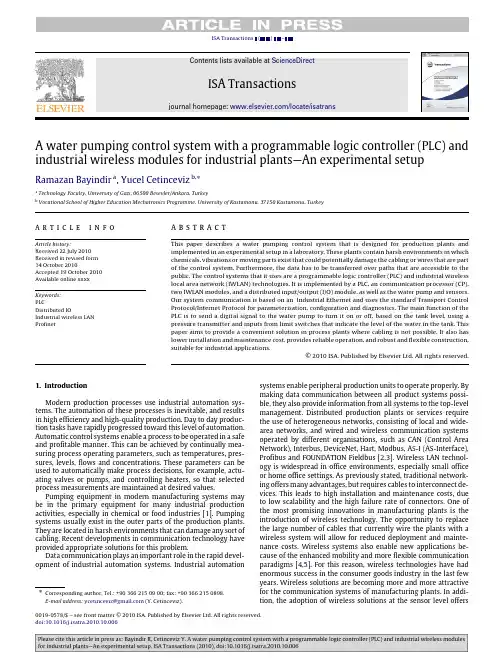
ISA Transactions()–Contents lists available at ScienceDirectISA Transactions journal homepage:/locate/isatransA water pumping control system with a programmable logic controller(PLC)and industrial wireless modules for industrial plants—An experimental setup Ramazan Bayindir a,Yucel Cetinceviz b,∗a Technology Faculty,University of Gazi,06500Besevler/Ankara,Turkeyb Vocational School of Higher Education Mechatronics Programme,University of Kastamonu,37150Kastamonu,Turkeya r t i c l e i n f o Article history:Received22July2010 Received in revised form14October2010Accepted19October2010 Available online xxxx Keywords:PLCDistributed IOIndustrial wireless LAN Profinet a b s t r a c tThis paper describes a water pumping control system that is designed for production plants and implemented in an experimental setup in a laboratory.These plants contain harsh environments in which chemicals,vibrations or moving parts exist that could potentially damage the cabling or wires that are part of the control system.Furthermore,the data has to be transferred over paths that are accessible to the public.The control systems that it uses are a programmable logic controller(PLC)and industrial wireless local area network(IWLAN)technologies.It is implemented by a PLC,an communication processor(CP), two IWLAN modules,and a distributed input/output(I/O)module,as well as the water pump and sensors. Our system communication is based on an Industrial Ethernet and uses the standard Transport Control Protocol/Internet Protocol for parameterisation,configuration and diagnostics.The main function of the PLC is to send a digital signal to the water pump to turn it on or off,based on the tank level,using a pressure transmitter and inputs from limit switches that indicate the level of the water in the tank.This paper aims to provide a convenient solution in process plants where cabling is not possible.It also has lower installation and maintenance cost,provides reliable operation,and robust and flexible construction, suitable for industrial applications.©2010ISA.Published by Elsevier Ltd.All rights reserved.1.IntroductionModern production processes use industrial automation sys-tems.The automation of these processes is inevitable,and results in high efficiency and high-quality production.Day to day produc-tion tasks have rapidly progressed toward this level of automation. Automatic control systems enable a process to be operated in a safe and profitable manner.This can be achieved by continually mea-suring process operating parameters,such as temperatures,pres-sures,levels,flows and concentrations.These parameters can be used to automatically make process decisions,for example,actu-ating valves or pumps,and controlling heaters,so that selected process measurements are maintained at desired values.Pumping equipment in modern manufacturing systems may be in the primary equipment for many industrial production activities,especially in chemical or food industries[1].Pumping systems usually exist in the outer parts of the production plants. They are located in harsh environments that can damage any sort of cabling.Recent developments in communication technology have provided appropriate solutions for this problem.Data communication plays an important role in the rapid devel-opment of industrial automation systems.Industrial automation∗Corresponding author.Tel.:+903662150900;fax:+903662150898.E-mail address:ycetinceviz@(Y.Cetinceviz).systems enable peripheral production units to operate properly.By making data communication between all product systems possi-ble,they also provide information from all systems to the top-level management.Distributed production plants or services require the use of heterogeneous networks,consisting of local and wide-area networks,and wired and wireless communication systems operated by different organisations,such as CAN(Control Area Network),Interbus,DeviceNet,Hart,Modbus,AS-I(AS-Interface), Profibus and FOUNDATION Fieldbus[2,3].Wireless LAN technol-ogy is widespread in office environments,especially small office or home office settings.As previously stated,traditional network-ing offers many advantages,but requires cables to interconnect de-vices.This leads to high installation and maintenance costs,due to low scalability and the high failure rate of connectors.One of the most promising innovations in manufacturing plants is the introduction of wireless technology.The opportunity to replace the large number of cables that currently wire the plants with a wireless system will allow for reduced deployment and mainte-nance costs.Wireless systems also enable new applications be-cause of the enhanced mobility and more flexible communication paradigms[4,5].For this reason,wireless technologies have had enormous success in the consumer goods industry in the last few years.Wireless solutions are becoming more and more attractive for the communication systems of manufacturing plants.In addi-tion,the adoption of wireless solutions at the sensor level offers0019-0578/$–see front matter©2010ISA.Published by Elsevier Ltd.All rights reserved.doi:10.1016/j.isatra.2010.10.0062R.Bayindir,Y.Cetinceviz /ISA Transactions ()–other advantages:continuous,high-resolution,ubiquitous sens-ing;support for mobility;redundancy;and compactness [6].To be able to use wireless communication technology in an industrial area,it is advisable to use products specially designed for such an environment.Wireless solutions are being used increasingly in process plants to meet the needs of modern work practices.Wireless technologies may have considerable savings installa-tion cost and a degree of flexibility not possible in wired systems.Wired control systems require trenching to lay new wire;repairing old wire or replacing stolen copper wire can be extremely expen-sive.Lower installation and maintenance costs,less interference from physical barrier problems,incongruity between standards be-ing minimised and the transmission bit rate being increased to 54Mbps are some of the specific profitable features of wireless net-working [7].There are several restrictions when using wireless systems that should be carefully taken into consideration,for instance,security issues,reliability,coverage area and fault tolerance.Insufficient information about these problems and their solutions can use away,despite the advantages of wireless networks [7].Several parameters must be considered for industrial wireless communication.In [8],all relevant parameters which might influence the timing behaviour and failure modes of industrial wireless communication systems were defined and described,as well as a model approach for industrial wireless transfer tests.Several studies have already been published on the use of wireless communication in industrial plants:in [7],one of the most notable analyses was carried out.In that work,a thorough survey of all industrial requirements was presented:scalability,cost-effectiveness,reliability,flexibility,high availability,immunity to interference,security,and many other factors.These issues are critical in hazardous and noisy environments.The existing wireless solution was reviewed,and the work explored potential matches between industry needs and existing wireless standards.A remote Automatic Meter Reading (AMR)system was developed for water supply organisations in [9].In that work,for implementing the system,an MR (magnetic resistance)sensor,Reed switch and CYBLE sensor type modules were used,and for installing for system communication,RF and Zigbee modules were used.In [10],the authors surveyed issues and appropriate solutions for wireless communication in industrial applications:fundamental problems,the usage of existing wireless technologies for this specific field of applications,and the creation of hybrid systems.In [4],wireless sensor networks are described in detail.In [11],the implementation of a multi-interface module (I2M)for drilling and ratifying processes was described.The work simulated a system with an Industrial Hydraulic Module (MHI-01),based on the IEEE1451standard.Wireless industrial sensors have been studied in a number of other works [12–16].In the studies reported in [17–20],wireless sensor modules were used for home automation.A servomotor remote control was carried out with a personal digital assistant (PDA),a PLC,a wireless device server and its driver in [21].The system communication was established by the wireless network card of the PDA,wireless device server,and RS-232port of the PLC.In [1],a small-capacity water pumping system was designed,constructed and tested using a PLC and frequency control.In that work,the system communication was established by cables.In other works,some examples of process control using a PLC and traditional cabling systems at the field level were carried out [1,22–30].PLCs are usually a main part of automatic control systems in industry.They are used for the internal storage of instructions to implement control functions,such as logic,sequencing,timing,counting and arithmetic.They control various types of machines and processes through digital or analogue input/output modules.PLCs are also used to monitor and control plants or equipment inFig.1.Block diagram of controlledprocess.Fig.2.Block diagram of water pump control system.industries such as telecommunications,water and waste control,energy,oil and gas refining,and transportation [23].This paper aims to provide a convenient solution in process plants where cabling is not possible.The proposed solution should lower the installation and maintenance costs,provide reliable operation,and be of robust and flexible construction for industrial applications.In this study,we used Siemens SCALANCE W IWLAN modules,which are different from the wireless sensor network (WSN)and WLAN systems used in previous reported studies.2.System designSystem design was carried out with consideration of environ-mental conditions and process details.Fig.1is an illustration of the controlled process.In this process,the Process Variable (PV)[31,32]is the water level in a tank.It is measured by a pressure transmit-ter and two limit switches (maximum and minimum water level)on the tank,and these values are the input into an automatic con-troller that actuates a pump based on the water levels.As shown in Fig.1,an open tank is supplied with an inflow of water,Q 1,from a water pump that can be controlled.The outflow from the tank,Q 2,is controlled by a manual valve according to the user’sneeds.The level of water in the tank is controlled according to the pressure and inputs to the controller from the two limit switches.Thus,the process control mode is on–off control.This is a discontinuous form of control action and is also referred to as two-position control.In this process,the on–off controller turns ‘on’when the water level is measured at its minimum value.The controller turns ‘off’when the water level reaches its maximum.The system block diagram,designed according to environmental conditions and the desired process control,is shown in Fig.2.2.1.Hardware structureAs shown in Fig.3,the whole system consists of three different units.The first unit is the PC.The PC runs a program called SIMATIC MANAGER,which is used to configure the hardware,the software package (STEP 7)as shown in Fig.5,and write a control program for the PLC.This control program is downloaded to the PLC through the MPI (Multi Point Interface)PC Adapter communication cable.R.Bayindir,Y.Cetinceviz /ISA Transactions ()–3Fig.3.System configuration diagram.Fig.4.Basic structure of a PLC.The second unit is the master node,and it consists of three parts:a PLC with digital and analogue modules,a CP (Communication Processor),and a Wireless Access Point.The last unit is on the client node side.This unit is located on the outer part of the control centre and is connected directly to the device to be controlled.The Wireless Client module,Distributed I/O Interface module and motor protection package (MPP)constitute the client node.•The Programmable Logic Controller (PLC).Typically,the basic functional components of a PLC system [33]are a processor unit,memory,power supply unit,input/output interface section,communications interface,and programming device.Fig.4shows the basic arrangement.•The processor unit or central processing unit (CPU)is the unit containing the microprocessor.This interprets the input signals and carries out the control actions,according to the program stored in its memory,communicating the decisions as action signals to the outputs.•The power supply unit is needed to convert the mains ACvoltage to the low DC voltage necessary for the processor and the circuits in the input and output interface modules.•The programming device is used to enter the required program into the memory of the processor.The program is developed in the device and then transferred to the memory unit of the PLC.•The memory unit is where the program for the microprocessor is stored.The memory unit also stores input data from for processing and buffers data for output.•The input and output sections are where the processor receives information from external devices and communicates information to external devices.The inputs might be from switches or sensors such as photo-electric cells,temperature sensors,or flow sensors.The outputs might be connected to motor starter coils,solenoid valves,or other actuators.Input and output devices can be classified by signal type,such as digital or analogue.4R.Bayindir,Y.Cetinceviz/ISA Transactions()–•The communications interface is used to receive and transmit data on communication networks.It manages device verifica-tion,data acquisition,synchronisation between user applica-tions,and connection management.In this study we used a Siemens S7313C Compact PLC which has 24DIs(Digital Inputs),16DOs(Digital Outputs),5AIs(Analogue Inputs),2AOs(Analogue Outputs),and a power supply(120/230V AC,24V DC,5A).•Communication Processor(CP).The PLC system Ethernet mod-ule is a communication processor for the S7family that con-nects the PLC to the network[29].An additional communication processor is used to allow communication between the PLC and IWLAN over TCP/IP.The CP343-1communications processor in our work is designed for operation in an S7-300programmable logic controller.It allows the S7-300to be attached to the In-dustrial Ethernet and supports PROFINET IO.•IWLAN modules.Wireless networking solves the physical bar-rier problems that are inherent to wiring,decreases installa-tion costs,improves flexibility when reconfiguring systems,and speeds up the deployment of the network[7].Industrial Wire-less LAN is a generic term covering functions and mechanisms that represent an enhancement of the IEEE802.11standard.Even the standard mechanisms of802.11provide a good degree of ruggedness for use in industrial applications.IWLAN,how-ever,also supports demanding applications and provides a par-ticularly high degree of real-time and deterministic scheduling, as required in PROFINET[34].•In this study,an IWLAN network was created using the new SCALANCE W generation components from Siemens.The radio network was set up using a SCALANCE W788-1PRO access point,and an Ethernet client module W744-1PRO was used to connect a node to an IWLAN.•Distributed I/O module.When a system is configured,the I/O to and from the process is often integrated centrally in the automation system.The ET200S distributed I/O system is a discrete modular,highly flexible DP slave for connection to process signals on a central controller or a field bus.ET200S supports field bus types PROFIBUS DP and PROFINET IO.This study used the ET200S-IM151-3PN standard with4DIs,2DOs, 4AIs and two24V power modules for the PROFINET IO bus[35].•Motor protection package.The motor protection package consists of a classical contactor,thermic switch,current measuring transducer(CMT),and voltage measuring transducer (VMT).The CMT is used for measuring sinusoidal and non-sinusoidal alternating currents,input current0to100A,and loop-powered output of4to20mA.The VMT is used for alternating current voltages from0.20to0.440V,and output signal0.10V/0(4).20mA.2.2.Software structureThe software for the control system was developed in the SIMATIC Manager.This is the central window which becomes active when the software package(STEP7)is started.The default setting starts the STEP7Wizard,which assists the programmer to create a STEP7project.Programmers can select the programming mode:ladder diagram(LAD),function block diagram(FBD),and instruction list(STL)[36].The project structure is used to store and arrange all the data and programs in order.The system software was completed in four steps.Step1 designs the solution to the automation task.Step2configures the hardware and the network[37],as shown in Fig.5.Step3creates the program in ladder diagram form.Step4transfers the program to the CPU.Finally,the software is tested for input status,program execution,and outputstatus.Fig.5.Hardware configuration in SIMATIC Manager.3.System implementationThis water pumping control system was designed as an on–off controller,operated by a stored program in the PLC.Data transmission to control the water pump was provided by the PLC and the Distributed I/O via IWLAN modules,as shown in Fig.6.The distributed I/O was connected to a SIMATIC CPU over an IWLAN wireless network.A Scalance W788-1PRO access point connected to the SIMATIC CPU via an Ethernet module over PROFINET services the cell.On the client side,a Scalance W744-1PRO client module and distributed I/O ET200S are used.Downstream from each IWLAN is a distributed I/O ET200S with4DIs,2DOs,and4 AIs,supplied with PROFINET.The cycle time(load caused by the program)is specified as50ms,which results in a typical reaction time of approximately140ms at an update time of32ms.3.1.System communicationSystem communication is formed of three main parts:the PC side,the access node,and the client side.The PC is connected to the master node via an MPI interface.The communication be-tween the access and client nodes is established through RF in IEEE 802.11[6–8]standard for industrial applications.The RF com-munication is performed using IWLAN modules operating on the 802.11b/g and802.11a standard with up to54Mbps speed and2.5 GHz frequency[38,39].Fig.7shows the minimal transaction times for32Byte data on the802.11a/b/g standard.The minimal transaction time to be reached for small packets in Wireless LANs lies between 120µs using802.11a or802.11g,each with54Mbit/s,and well over1000µs using802.11b.The requirements of many industrialsystems can be provided by these WLAN components[40].The client nodes,as shown in Fig.6,are connected directly to the device to be controlled via conventional command components.The communication is established over a PROFINET field bus during the network configuration part of the software package (STEP7).PROFINET enables distributed field devices(I/O devices such as signal modules)to be integrated directly in the Industrial Ethernet.During configuration with STEP7,these field devices are assigned to a central controller(I/O Controller).Existing modules or devices can continue to be used with PROFINET-compatible interfaces or links.PROFINET provides new functions and applications for wireless communication with an Industrial Wireless LAN.The functions implemented here are based on a PROFINET network via a Wireless LAN[6].The following functions are available for the data traffic between the user program of the S7-300CPU and the PROFINET IO devices via a CP as a PROFINET IO controller,as shown in Fig.8.R.Bayindir,Y.Cetinceviz/ISA Transactions()–5 Fig.6.A photograph of the designedsystem.Fig.7.Minimal transaction times for32Byte data[40].•PNIO_SEND(FC11)•PNIO_RECV(FC12).In addition,the following function blocks are available for diagnostics:•PNIO_RW_REC(FB52)(not used in this application)•PNIO_ALARM(FB54)(not used in this application).The blocks are included in the SIMATIC_NET_CP library.Block FC11(PNIO_SEND)is used for transferring process data and is called cyclically in the user program.The process data are made available in memory,accessible as a data block.The FC11 transfers these process data(outputs)to the CP to forward them to the PROFINET IO devices.Block FC12(PNIO_RECIEVE)is used to accept the process data from PROFINET IO devices(inputs of the controller)and transfers the IO provider status(IOPS)from the PROFINET IO devices to the specified input areas[38].3.2.System operationPumping equipment may be a major part of modern manufac-turing and industrial production systems for chemical,food,and other industries[1].Pumping systems usually exist in the outer parts of the production plants and are found in harsh environments that could damage any sort of cabling.Therefore,this system was designed to be wireless,using IWLAN modules for communication and a PLC for control.Where a number of plants are supplied with water from one set of pumps,a very effective plan is through a ring-main,which supplies water to all the feeders.Control systems for these systems operate by monitoring the water level.In this study,the water level is measured by a pressure transmitter and for precaution by maximum and minimum limit switches.Level measuring with the pressure method:the heights of liquids are directly proportional to their pressure on the base.If base pressure of the liquid formulation had been doneP=d×g×h.(1) d water=1000kg/m3(constant value).g=9.81N/kg(constantvalue).6R.Bayindir,Y.Cetinceviz/ISA Transactions()–Fig.8.Typical sequence of FC11and FC12calls in the CPU cycle.Fig.9.Flow chart of pump control.R.Bayindir,Y.Cetinceviz/ISA Transactions()–7Fig.10.Program structure of the system:(a)subordinate blocks;(b)data block variables;(c)Scaling block for pressure;(d)LAD view of pump control function block. Here d is the density of the liquid.This is a constant value,accordingto the liquid used.g is the acceleration due to gravity.P=1000×9.81×h N/m2(1pascal=105bar).(2)Using the above formulation,the values reported in Table1can beobtained.SIMATIC Step7V5.4software has been used for programmingthe system.After a flow chart of operation had been formed,asshown in Fig.9,the program structure of the system was createdwith organisation blocks,a function block,and data blocks,andthen the call for subordinate blocks as shown in Fig.10a with adata block as shown in Fig.10b was programmed in the hierar-chy.The application function block contains application-relatedsignal processing,such as scaling,alarm detection or control andTable1calculation[41].Symbolic names are given in the symbol table(for example,Pressure=level and controldb).To scale values of8R.Bayindir,Y.Cetinceviz/ISA Transactions()–pressure,current and voltage converting block as shown Fig.10c was used from the standard library in STEP7.Fig.10d shows the LAD view of the system program.The system program was config-ured to switch the pump on when the water level drops and switch it off when the tank is full.When the tank is full,the control system signals the pump to switch off,via wireless IWLAN modules.The tank is closed above its maximum fill level,preventing overflow. The pump system operates as follows.The water outflow from the tank passes through a manually controlled valve,operated by the user.When the water level triggers the low-level limit switch,a contact closes and the transmitter sends a digital signal and the pressure transmitter,VMT and CMT send a4–20mA signal to the controller via the wireless client module and access point.If the pump current value is not>1A and the pump voltage value is not<220V,the PLC’s main function is to send a digital signal to the pump,which turns on and fills the water tank.When the water tank is full,the pressure transmitter sends the relevant value which has been scaled,being the high level,or for precaution the capaci-tance switch opens a contact at the transmitter,and the transmitter sends an‘‘off’’signal to the controller.The PLC then sends a digital output to the water pump to turn it off.4.ConclusionIWLAN modules and PLC controllers are the natural technol-ogy choice for process automation and control.[7,8]Wireless net-working provides the needed flexibility,low maintenance cost,and scalability in the design and control of a plant.In this work,we discussed the design and implementation of a water pumping pro-cess.The proposed architecture and results demonstrate the fea-sibility of using IWLAN protocols to communicate effectively with PLCs.The system was tested using an industrial application and it had a very satisfactory performance.Conventional,wired control systems require trenching to lay new wire;repairing old wire or replacing stolen copper wire can be extremely expensive.In this study,wireless communication for the water pump control solved these problems and provided a clear advantage over wired control systems.AcknowledgementThis study was supported from the Scientific Research Project Commission of the Gazi University,under grant07/2009-06. References[1]Ali A,Al_Soud M,Abdallah E,Addallah S.Water pumping system with PLC andfrequency control.Jordan Journal of Mechanical and Industrial Engineering 2009;3:216–21.[2]Mossin EA,Pantoni RP,Brandão D.A fieldbus simulator for training purposes.ISA Transactions2009;48:132–41.[3]Neumann munication in industrial automation—what is going on?Control Engineering Practice2007;15:1332–47.[4]Gungor VC,Lambert FC.A survey on communication networks for electricsystem puter Networks2006;50:877–97.[5]Brevi D,Mazzocchi D,Scopigno R,Bonivento A,Calcagno R,Rusina F.Amethodology for the analysis of802.11a links in industrial environments.In:Proc.of the7th IEEE international workshop on factory communication systems.2006.p.165–74.[6]Flammini A,Ferrari P,Marioli D,Sisinni E,Taroni A.Wired and wirelesssensor networks for industrial applications.Microelectronics Journal2009;40: 1322–36.[7]Egea-Lopez E,Martinez-Sala A,Vales-Alonso J,Haro JG,Malgosa-Sanahuja J.Wireless communications deployment in industry:a view of issues,options and puters in Industry2005;56:29–53.[8]Gnad A,Krätzig M,Rauchhaupt L,Trikaliotis S.Relevant influences in wirelessautomation.In:Proc.of the7th IEEE international workshop on factory communication systems.2008p.341–8.[9]Kim H,Ayurzana O.Improvement of data receive ratio in remote water metersystem by upgrading sensor.International Journal of Control,Automation,and Systems2009;7:145–50.[10]Swıllıg A,Matheus K,Wolisz A.Wireless technology in industrial networks.Proceedings of the IEEE2005;1130–51.[11]Batista EA,Silva ACR,Gonda L,Pereira MC,da Silva I,Ferreira WM.et al.IEEE1451-based Multi-Interface Module(I2M)for industrial processes au-tomation.In:IEEE sensors applications symposium.2008.p.220–4.[12]Howitt I,Manges WW,Kuruganti PT,Allgood G,Gutierrez JA,Conrad JM.Wireless industrial sensor networks:framework for QoS assessment and QoS management.ISA Transactions2006;45:347–59.[13]Ramamurthy H,Prabhu BS,Gadh R,Madni AM.Wireless industrial monitoringand control using a smart sensor platform.IEEE Sensors Journal2007;7:611–8.[14]Gaderer G,Loschmidt P,Mahmood A.A novel approach for flexible wirelessautomationin real-time environments.In:IEEE international workshop on factory communication systems.2008.p.81–4.[15]Liu X,Goldsmith A.Wireless network design for distributed control.In:IEEEconference on decision and control.2004.p.2823–9.[16]Zhuang LQ,Goh KM,Zhang JB.The wireless sensor networks for factory au-tomation:issues and challenges.Emerging Technologies&Factory Automa-tion2007;141–8.[17]Yuksekkaya B,Kayalar AA,Tosun MB,Ozcan MK,Alkar AZ.A GSM.In:IEEEtransactions on internet and speech controlled wireless interactive home automation system,consumer electronics,vol.52.2006.p.837–43.[18]Chung WY,JuOh S.Remote monitoring system with wireless sensors modulefor room environment.Sensors and Actuators B:Chemical2006;113:64–70.[19]Alkar AZ,Buhur U.IEEE transactions on an internet based wireless homeautomation system for multifunctional devices,consumer electronics,vol.51.2005.p.1169–74.[20]Oksa P,Soini M,Sydanheimo L,Kivikoski M.Kilavi platform for wirelessbuilding automation.Energy and Buildings2008;40(9):1721–30.[21]Wu RC,Wu HC,Teng JH,Huang CC.The realization of PLC wireless remotegraphic control by PDA.In:IEEE region10conference.2007.p.1–4.[22]Ogawa M,Henmi Y.Recent developments on pc+plc based control systems forbeer brewery process automation applications.In:SICE–ICASE international joint conference.2006.p.18–21.[23]Shankar KG.Control of boiler operation using PLC-SCADA.In:Proc.of theinternational multi conference of engineers and computer scientists.2008.p.19–21.[24]Honda A,Okano F,Ooshima K,Akino N,Kikuchi K,Tanai Y,et al.Applicationof PLC to dynamic control system for liquid Hecryogenic pumping facility on JT-60U NBI system.Fusion Engineering and Design2008;83:276–9.[25]Bradu B,Gayet P,Niculescu SI.A process and control simulator for large scalecryogenic plants.Control Engineering Practice2009;17:1388–97.[26]Behary M,Ah King RTF,Rughooputh HCS.Automation of sugar boiling processin batch vacuum pans using ABB-freelance PLC(AC800F)and conductor NT SCADA.In:IEEE international conference on industrial technology.2004.p.853–8.[27]Abdallah S,Nijmeh S.Two axes sun tracking system with PLC control.JordanJournal of Mechanical and Industrial Engineering2009;3:216–21.[28]Abdallah S,Abu-Mallouh R.Heating systems with PLC and frequency control.Energy Conversion and Management2008;49:3356–61.[29]Da’na S,Sagahyroon A,Elrayes A,Al-Ali AR,Al-Aydi R.Development ofa monitoring and control platform for PLC-based puterStandards&Interfaces2008;30:157–66.[30]Ozdemir E,Karacor M.Mobile phone based SCADA for industrial automation.ISA Transactions2006;45:67–75.[31]Medida S.Pocket guide on industrial automation.first ed.Perth(Australia).2008.[32]Parr EA.Programmable controllers an engineer’s guide.third ed.Burlington:Oxford;2003.[33]Bolton W.Programmable logic controllers.fourth ed.Burlington:Oxford;2006.[34]Industrial wireless LAN-industrial features and current standards.Nuernberg,Germany.2006..[35]ET200S.Distributed I/O system operating instructions.2008./WW/view/en/1144348.[36]STEP7Getting Started..[37]Fadaei A,Salahshoor K.Design and implementation of a new fuzzy PIDcontroller for networked control systems.ISA Transactions2008;47:351–61.[38]Quality of Service with Scalance W Simatic Net.November2008..[39]Lugli AB,Santos MMD,Franco LRHR.A computer tool to support in design ofindustrial Ethernet.ISA Transactions2009;48:228–36.[40]Winter CH.Industrial wireless LANs with Siemens SCALANCE W.Aachen,Germany.2004.[41]Diedrich C,Russo F,Winkel L,Blevins T.Function block applications in controlsystems based on IEC61804.ISA Transactions2004;43:123–31.Ramazan Bayindir is an Associate Professor Dr.at the Technical Education Faculty,Department of Electrical Education,Gazi University,Ankara,Turkey.He graduated from the Electrical Education Department,Technical Education Faculty in Gazi University,Ankara,Turkey,in1992.He holds M.Sc.and Ph.D.degrees from Gazi University,Ankara,received in1998and2002,respectively.His main interests include power electronics,electrical machines,power factor correction, microcontroller programming.Yucel Cetinceviz is an Instructor at the Kastamonu Vocational High School, Mechatronics Department of Kastamonu University,Kastamonu,Turkey.He graduated from the Electrical Education Department in Gazi University,Ankara, Turkey,in2006.He has been performing his M.Sc.studies on Internet-based industrial automation.His main interests include programmable logic controllers, process control,and Supervisory Control and Data Acquisition(Scada).。
外文文献(一)原文DUAL FULL BRIDGE PROTECTED MOTOR DRIVER(A3976)The A3976 is designed to drive both windings of a bipolar stepper motor or bidirectionally control two DC Motors. Both H-Bridges are capable of continuous output currents of up to+/- 500 mA and operating voltages to 30V. Free wheeling, substrate isolated diodes are included for output transient suppression when switching motors or other inductive loads. For each bridge the PHASE input controls load current polarity by selecting the appropriate source and sink driver pair. The ENABLE input, when held high, enables the respective output H-bridge. When both ENABLE pins are held low the device will enter SLEEP mode and consume less than 100mA. The 3976 is protected to ensure safe operation in harsh operating environments and was designed specifically for automotive applications. Protection circuitry will check for open or shorted load, motor lead short to ground or supply, VBB overvoltage, VCC undervoltage, and thermal shutdown. If any of these conditions are detected the outputs will be disabled and fault information will be output to diagnostic pins FAULT1 and FAULT2. The 3976 is supplied in a choice of two power packages, a 16-lead plastic DIP with a copper batwing tab (suffix ‘B’), and a 24-lead plastic SOIC with a copper batwing tab (suffix ‘LB’). In both cases, the power tab is at ground potential and needs no electrical isolation.FEATURES(1)30 V , ±500 mA Continuous Output Rating(2)35V Load Dump Survival(3)Output Short Circuit Protection(4)Coded Fault Diagnostic Outputs(5)Low Current Standby Mode(6)Open Load Monitor(7)Low Current Standby Mode(8)VBB Over Voltage Shutdown(9)Internal Thermal Shutdown Circuitry(10)Internal Low Parasitic Free Wheeling Diodes(11)Crossover Current ProtectionABSOLUTE MAXIMUM RATINGSat TA = +25°COperating Supply Voltage, VBB .................... 30 VNon-Operating Supply Voltage..................... 35 V Output Current, IOUT ............................±500 mA* Logic Supply Voltage, VCC.......................... 7.0 V Fault Output Voltage ................................... 7.0 VLogic Input Voltage Range, VIN.......................... -0.3 V to VCC + 0.3 VPackage Power Dissipation (TA = +25°C), PDA3976KLB..................................2.2 WA3976KB ....................................2.9 WOperating Temperature Range,TA ..............................-40°C to +125°CJunction Temperature, TJ .........................+150°C Storage Temperature Range, TS...............................-55°C to +150°C* Output current rating may be limited by duty cycle, ambient temperature, and heat sinking. Under any set of conditions, do not exceed the specified current rating or ajunction temperature of 150°C.PART NUMBER PACKAGE RØJA RØJTA3976KLB24 Lead SOIC56︒C/W6︒C/WA3973KB16 Lead DIP43︒C/W6︒C/WInput LogicPHASE ENABLE OUTA OUTBX 0 OFF OFF0 1 LOW HIGH1 1 HIGH LOWFault LogicFault Condition FAULT1FAULT2Thermal Shutdown LOW LOWShort to Battery or Open Load LOW HIGHShort to Ground HIGH LOWNormal Operation HIGH HIGHAPPLICATION NOTESOpen Lead Protection. During normal PWM operation diagnostic circuitry will look for a minimum source current level after a bridge is signalled on. Additionally, the diode flyback is monitored on the proper output. The logic will signal a fault and disable the outputs if it determines that the current is below the minimum level AND no flyback is occurring. If the inductive load is too large, the current would take too long to reach the minimal level and afalse open load would be reported. It is recommended that the inductive load be less than38mH.Short Circuit Protection. Internal sense resistors in series with VBB and ground willtrip the fault circuitry if greater than 1.1A is detected. To prevent false overcurrent events due to reverse recovery spikes of the clamp diodes, the current monitor is blanked for 5us after a high side is signalled to turn on. If an additional input command follows after the initial fault, the selected pair of drivers will pulse on for the 5us blanking duration. The short circuit fault will remember the input state where the fault occurred and will wait for that particular logic state after the short has been removed before normal operation is allowed to resume.Thermal Protection. Circuitry turns OFF all drivers when the junction temperaturereaches 170°C typically. It is intended only to protect the device from failures due to excessive junction temperatures and has a hysteresis of approximately 15°C.Layout. The printed wiring board should use a heavy ground plane. For optimum electricaland thermal performance, the driver should be soldered directly onto the board. The load supply pin, VBB, should be decoupled with an electrolytic capacitor (> 47 μF is recommended) placed as close to the device as possibleEnengy or Solar EnegryEnergy means the power which does work and drives machines. All living things (including humans) rely on the sun as a source of energy. Coal, petroleum, and natural gas are energy sources available today because organisms in the past captured sunlight energy and stored it in the complex organic molecules that made up their bodies, which were then compressed and concentrated. With the development of society, a large of energy sources have been used,such as coal, petroleum, natural gas, geothermal energy, nuclear fission power, nuclear fusion power, solar energy, and Hydrogen gas. however, under the circumstances, the quantity of energy source is limited. unlimited usage of energy source results in energy crisis. At present, most of the energy consumed by humans is produced from fossil fuels. The greatest recoverable fossil is in the form of coal and lignite. Although world coal resources are enomous and potentially can fill energy needs for a century or two, their utilization is limited by environmental disruption from mining and emissions of carbon dioxide and sulfur dioxide. These would become intolerable long before coal resources were exhausted. Only a small percentage of coal and lignite has been utilized to date, whereas much of the recoverable petroleum and natural gas has already been consumed. Petroleum has several characteristics that make it superior to coal as a source of energy. Its extraction causes less environmental damage than does coal mining. It is a more concentrated source of energy than coal, and it burns with less pollution, and it can be moved easily through pipes. These characteristics make it an ideal fuel for automobiles.Since first commercial oil well in 1859, somewhat more than 100 million barrels of oil have been produced in the United States, most of it in recent years. In 1990 world petroleumconsumption was at a rate of about 65 million barrels per day. Projected use of petroleum and natural gas indicates rapid depletion. Alaskan oil can help the petroleum supply only temporarily. Peak world petroleum resources production will be reached within a few years. Since the first "energy crisis" of 1973-1974, some concrete actions have even taken place. However, the several-fold increase in crude oil prices since 1973 has extacted a toll. In the U.S. and other industrialized nations, the economy has been plagued by inflation, recession, unemployment, and obsolescence of industrial equipment. The economies of some petroleum-deficient developing countries have been devastated by energy prices.Energy crisis was accompanied by worldwide shortages of some foods and minerals, followed in some cases by surpluses, such as the surplus wheat resulting from increased planting and a copper surplus resulting from the efforts of copper-producing nations to acpuire foreign currency by copper export.As known to all,the availability and cost of energy has become dominant factors in society today. Obviously, solving the "energy crisis" makes good sense. Many schemes has been proposed for conserving present energy resources and for developing new ones. It is always possible to use less energy in any process. Therefore, energy engineer is created and developed. The first goal of energy engineer is to determine the methods by which energy utilization is reduced but the output remains the same, or even increases.The second goal is to determine which methods of using less energy are cost effective.Conventional engineering techniques are used to evaluated the mechanisms of energy use. Economic considerations are of equal importance and life cycle cost and saving techniques are used to determine cost-effective measures. The evaluation focuses on those uses which are significant in the overall picture and attempts to determine those technical measures that can reduce usage and save money.Meanwhile, looking for ideal energy sources is also very important to solve energy crisis. The recipe for an ideal energy source calls for one that is unlimited in supply, widely available, and inexpensive; it should not add to the earth's total heat burden or produce chemical air and water pollutants. Solar energy fulfills all of these criteria. Solar energy does not add excess heat to that which must be radiated from the earth. On a global basis, utilization of only a small fraction of solar energy reaching the earth could provide for all energy needs.Solar energy is unlimited in supply, but its exploitation and utilization are limited owing to the limitation of technology and conditions. Solar energy utilization needs an enormous amount of land, and there are economic and environmental problems related to the use of even a fraction of this amount of land for solar energy collection. Certainly, many residents of Arizona would not be pleased at having so much of the state devoted to solar collectors, and some environmental groups would protest the resultant shading of rattlesnake habitat. Solar power cells for the direct conversion of sunlight to electricity have been developed and are widely used for energy in space vehicles. With present technology, however, they remain too expensive for large-scale generation of electricity. Therefore, most schemes for the utilization of solar power depend upon the collection of thermal energy, followed by conversion to electrical energy. The simplest such approach involves focusing sunlight on a steam-generating bioler. Parabolic refkectors can be used to focus sunlight on pipescontaining heat-transporting fluids. Selective coatings on these pipes can be used so that only a small percentage of incident energy is reradiated from the pipes.(二)翻译全双桥电机保护驱动器(A3976)A3759是一种用来驱动双极性步进电机双绕组的单片集成电路,也可以用来双向控制两台电动机。
外文文献翻译(附原文)外文译文一:产业集群的竞争优势——以中国大连软件工业园为例Weilin Zhao,Chihiro Watanabe,Charla-Griffy-Brown[J]. Marketing Science,2009(2):123-125.摘要:本文本着为促进工业的发展的初衷探讨了中国软件公园的竞争优势。
产业集群深植于当地的制度系统,因此拥有特殊的竞争优势。
根据波特的“钻石”模型、SWOT模型的测试结果对中国大连软件园的案例进行了定性的分析。
产业集群是包括一系列在指定地理上集聚的公司,它扎根于当地政府、行业和学术的当地制度系统,以此获得大量的资源,从而获得产业经济发展的竞争优势。
为了成功驾驭中国经济范式从批量生产到开发新产品的转换,持续加强产业集群的竞争优势,促进工业和区域的经济发展是非常有必要的。
关键词:竞争优势;产业集群;当地制度系统;大连软件工业园;中国;科技园区;创新;区域发展产业集群产业集群是波特[1]也推而广之的一个经济发展的前沿概念。
作为一个在全球经济战略公认的专家,他指出了产业集群在促进区域经济发展中的作用。
他写道:集群的概念,“或出现在特定的地理位置与产业相关联的公司、供应商和机构,已成为了公司和政府思考和评估当地竞争优势和制定公共决策的一种新的要素。
但是,他至今也没有对产业集群做出准确的定义。
最近根据德瑞克、泰克拉[2]和李维[3]检查的关于产业集群和识别为“地理浓度的行业优势的文献取得了进展”。
“地理集中”定义了产业集群的一个关键而鲜明的基本性质。
产业由地区上特定的众多公司集聚而成,他们通常有共同市场、,有着共同的供应商,交易对象,教育机构和其它像知识及信息一样无形的东西,同样地,他们也面临相似的机会和威胁。
在全球产业集群有许多种发展模式。
比如美国加州的硅谷和马萨诸塞州的128鲁特都是知名的产业集群。
前者以微电子、生物技术、和风险资本市场而闻名,而后者则是以软件、计算机和通讯硬件享誉天下[4]。
Application of Fuzzy Logic Control to the Design ofSemi-Active Suspension SystemsC.F. Nicolhst, J. Landaluzet, E. Castrillot, M. Gast6nS and R. ReyerotTIKERLAN Technological Research $QUINTON HAZELL SPAINCenter 01400 Llodio, SpainControl Engineering DepartmentP.O. Box 146, 20500 Mondragh, Spaincfnicolas @ ikerlan.esAbstractThis paper describes the practical application of fuzzy logic to the design of semi-active suspension systems control strategies. The intelligent suspension systems are based on a continuously adjustable shock absorber and an Electronic Control Unit. Two different fuzzy approaches are described: the first strategy is based on the actions of the driver and the second is based on the vehicle dynamics. Both simulation and experimental on-road remits are presented. The system was tested in a number of vehicles and the results are compared with those obtained with other conventional control strategies based on selection amongst several discrete damping settings. The main advantage of the proposed fumy strategies is the smelt number of required sensors, achieving similar performances than other control algorithms with less cost. Due to the simplicity of the sensitization, the described fuzzy control systems can be easily adapted to any vehicle.1. IntroductionRecently, fuzzy logic control has been applied successfully in some automotive vehicle sub-systems, including engine idle speed, automatic transmission, cruise controller and others [1], [4]. Amongst them active and semi-active suspensions havebeen attracted an increased number of practical applications. The fuzzy logic enables the heuristic rule-based techniques commonly applied to discretely variable damping systems to be extended for use in the continuously variable damping situation, without significantly increasing the size of the rule-base [4]. These techniques are well suited for dealing with the nonlinear behavior of the suspension elements, for instance, of the continuously adjustable shock absorbers. The fuzz y methods have been employed it: suspension designs based in both driver actions [3] and vehicle dynamics [2].In the last few years, IKERLAN has applied fuzzy logic in many areas: domestic appliances (microwave ovens, washing machines, etc.), robotics (autonomous robot guidance, position control) and industrial control (climatic controllers, multimode temperature regulators). In the field of the automotive, IKERLAN has been working on semi active suspensions and has developed and tuned up several prototypes, based on both the actions of the driver and vehicle dynamics [7]. Between the different controllers designed and implemented the intelligent systems based on fuzzy logic have an important place [SI, [9]. A basic element of the suspension systems carried out is the continuously adjustable shock absorber developed by Quinton Hazel. This enables the design of high performance suspension systems.After mentioning the components of the whole system, this paper firstly describes the application of the fuzzy logic to the development of a semi-active suspension system based on the driver actions. The system was developed and firstly implemented in both a Renault R- 11and the Land Rover Discovery vehicles [SI, and recently it was improved, implemented and tested in a SEAT-VW Cordoba GTI vehicle [9]. The system is simple, although from the point of view of results, the performance is similar to that obtained from other much more costly and complex systems based on vehicle dynamics. The controller structures as well as the fuzzy rule base are specially described.Next, the paper explores the application of fuzzy logic to the design of semi-active suspensions based on vehicle dynamics. As a basis, the reasoning of the classic “skyhook” algorithm was consid ered, but trying to obtain similar results with muchless sensors, which is one of the drawbacks of these systems, a design based on the minimizing of the sprung mass acceleration was carried out. This kind of designs was treated only in simulation.The experimental results obtained with the first type of intelligent controllers are presented and compared with those obtained with other conventional control strategies implemented in some popular commercial vehicles. The results obtained in simulation with the policies based on vehicle dynamics are presented as well.2. Description of the system2.1. System componentsAs usual, the electronic suspension systems consist of the following basic elements: four continuously adjustable shock absorbers, an Electronic Control Unit and the sensors required. The sensor system depends on the control policy to be implemented and it is different for algorithms based on driver actions than for those based on vehicle dynamics.2.2. Continuously adjustable shock absorbersThe continuously adjustable shock absorbers are the main elements of the suspension systems and they determine, to a great extent, the specifications to be obtained by a semi-active suspension system. The distances between the hardest and softest damping positions must be as big as possible, and the responses time as short as possible. The Quinton Hazel1 variable shock absorber integrates an electro valve, and depending on the current applied to it, the oil flow between the compression chamber and the reverse chamber of the shock absorber is adjustable and controlled. This enables the damping forces to be varied continuously in both expansion and compression.The electro valve can be fitted without major modifications in a single ortwin-tube shock absorber and be located at the top of the rod, in the low frequencypart. So, externally the adjustable damper is similar to a standard one, passing the oil through a counter-rod. The electric signal fed to the control electro valve comes in through the hollow piston rod.Figure 1 presents the working foundation of the continuously adjustable shock absorber, in both expansion and compression. Depending on the intensity passing through the electro valve, between 0 and 0.8 A, a variable section way though is opened and it causes a pressure drop, and therefore, a change in the force acting on the piston rod. The response time is 10 ms, which is very important to obtain a minimal phase shift between the damping force required and the force obtained, especially when semi-active control algorithms based on vehicle dynamics are introduced. Figure 2 shows the non-linear mathematical model achieved from the experimental force velocity curves corresponding to the rear damper in theSEAT-VW Cordoba GTI vehicle. The response obtained with the standard shock absorber is shown as well.2.3. Control unitA preindustrial Electronic Control Unit was developed for general and modular purposes. It enables all types of algorithms to be implemented, from the simplest ones based on the actions of the driver to the most complicated ones based on vehicle dynamics.Figure 1.Working basis of the shock absorber with the electro valve. Above:compression. Below: expansionFigure2. Shock absorber simulation modelSMD technology was used and the latest recommendations at EMC level for car equipment have been taken into account. It includes a CAN bus as a standard feature, which can be used for configuration, diagnostics or integration with other Control Units.The most important specifications of the ECU can be summarized as follows: based on the SAB80C166 micro controller, it has 32K of RAM, 32K of EPROM and16x16 bits of EEPROM. 10 analog channels and 10 digital channels are available as inputs, as well as 4 independent current outputs for the shock absorbers, a RS-232-C serial communications port, CAN bus and digital channels for information LEDs as outputs. This hardware allows the control loop to be closed every 10 ms for the type of algorithms described in this paper.2.4. Sensor systemsThe sensor required depends on the kind of semi-active controller designed. On the one hand, for the control strategies based on the driver actions, only one or two sensors have to be specifically installed: one to determine the: steering wheel angle and another to determine the throttle valve position (or alternatively the position of the accelerator pedal). It is supposed that the vehicle supplies a digital signal proportional to the speed, which is what happens in most vehicles nowadays. Moreover, the system uses the brake pedal switch, as well as an accelerometer integrated in the Electronic Control Unit circuit to measure the vertical accelerations of the sprung mass. For the steering wheel angle both potentiometer and relative optical encoders have been used.On the other hand, due that for the design of semi-active intelligent controllers a quarter-vehicle model was used, it is common to need two sensors for everyquarter-car: two accelerometers, one accelerometer and a displacement sensor, etc. Anyway, the fuzzy logic was applied to minimize the number of sensors required and only one accelerometer on the sprung mass for every quarter-car has to be installed.From the sensors installed the variables observed and estimated taken into account by the driver actions based algorithms are as follows: the speed of the vehicle, the steering wheel angle, the speed of the steering wheel, the throttle valve position, brake pedal pressure and the vertical acceleration of the sprung mass. The variable taken into account by the vehicle dynamics based controller is the acceleration of the sprung mass of every quarter-car.3. Controller based on driver actions3.1. Controller designIn this case the fuzzy controller works like a "feed forward" system, selecting a suitable operating point for the shock absorbers according to the actions taken by the vehicle driver. The knowledge base of the fuzzy controller relates to the level of damping with specific driving conditions according to observations from a set of sensors installed in the vehicle.The following are used as control system inputs: steering wheel position, steering wheel rotation speed, vertical acceleration of the vehicle, degree of longitudinal acceleration of the vehicle (accelerator pedal position or throttle valve position), and longitudinal speed of the vehicle and brake contact.The variable damping level is calculated in a continuous range, in order to obtain optimum operation of the semi active damping system. A priori, this system can be relatively robust compared to the operation of the shock absorbers, achieving suboptimum operation even when the precision and repeatability in fixing the damping level of the shock absorber are not very high.The rules take comfort as .the control objective only when safety is not severely diminished, with the shock absorbers operating in the softest areas, although from the variables considered harder values are reached when required, i.e. giving more weight to safety over comfort in the course of abrupt maneuvers.Figure3. Fuzzy selection criteriaWhen designing a rule-bowed inference system, theoretically a general formulation depends on rules with as many antecedents as considered inputs. In practice this leads to a cumbersome system that needs a powerful CPU to compute the results in a restricted real-time environment. Due to the fact that the more restrictive conclusion is the one preferred (safety preservation), then a more simple solution may be conceived. The finally implemented solution is based on a modular approach that allows many input variables and criteria for suspension operation to be incorporated (see Figure 3).Due to the problems involved in incorporating negative reasoning in fuzzy logic and the complexity of system tuning when the knowledge base incorporates rules with a large number of antecedents, the controller was designed as a hybrid system, with a fuzzy knowledge base and a non-fuzzy heuristic selection algorithm: From the observation of different driving parameters multiple choices for the damping level are inferred. The actual value is determined by means of a selection algorithm choosing the option that guarantees the higher level of safety.When ON/OFF signals (brake) require a hard level of damping, and then some softening delay may be introduced for prevention of undesirable softening when asuccession of abrupt maneuvers is performed.3.2. Controller structure and rule baseThe controller basically consists of 3 parts:● Input pre-processing:Antecedents are established for use in the definition of the rules for the fuzzy system. It includes all the filtering and sensor signal processing required by the system.●F u z y inference system:Depending on the inference system required, a choice has to be made between an implementation procedure which provides a lot of flexibility in reprogramming the system (possibility of changing the rules and functions used in the fuzzy system on line), and a system which requires a higher level of information pre-processing, but considerably reducing the number of operations to be carried out in real time (based on LUT -Look-Up Tables).●Post processing (selection algorithm): This determines the damping value to be applied at each moment, bearing in mind the different values inferred.The fuzzy system consists of 4 different kinds of knowledge bases. Each rule base considers 2 antecedents and 1consequent as follows:●Vehicle velocity vs. Steering Angle.●Vehicle velocity vs. Steering Speed.●Vehicle velocity vs. Longitudinal Acceleration.●Vehicle velocity vs. Longitudinal Deceleration.●Vehicle velocity vs. Vertical acceleration.One of the antecedents is always the longitudinal speed of the vehicle, and the consequent is the damping level mapped to input current to the shock absorber electro valve (in the described controller the same current was applied at the front and rear shock absorbers simultaneously).Different linguistic variables are defined for the inputs, depending on the working ranges of the variables, in order to obtain a proper characterization of the driving conditions. But for the outputs only three linguistic terms are considered: SPORT, NORMAL and COMFORT, which refer to the hardest, an intermediate and the softestvalue respectively.Although only three values are considered for the output, selecting Centre of Area method for fuzzy makes the working range of the output values continuous. Alternatively, a system with only a discrete set of output values can be obtained by means of simply changing the fuzzy (i.e. using a maximum criterion).For each of the variables processed, and mentioned previously, a characteristic surface has been generated (rated in relation to the speed of the vehicle and the variable processed). For example, Figure 4 shows the characteristic surface created for the steering wheel position (corresponding to the SEAT-VW Cordoba GTI vehicle), in which an auxiliary antecedent is really being considered; centripetal acceleration, which depends on the steering wheel position; longitudinal speed and other parameters characteristic of the vehicle.As pointed out earlier, due to the characteristics of fuzzy logic, it is complicated to design a system with negative reasoning, which is precisely what is required when, due to the driving circumstances, the system has to maintain operational safety.As mentioned earlier, the formulation of the system gives priority to safety over comfort in the driving conditions. By default, the state of the suspension will be that which guarantees a high level of comfort, although when driving circumstances require harder damping, to ensure the safety and stability of the vehicle during man oeuvres, then safety shall have priority over comfort.Figure4. Steering angle characteristic surface.3.3. ImplementationOnce tuned, the proposed fuzzy control system works with a fixed knowledge base (adaptive characteristics have not been implemented yet). The recomputed result of the fuzzy inference for a discrete set of values for the antecedents is stored in table form in the ECU EPROM. In real time, this look-up table (LUT) is used for the computation of the fuzzy output by means of multiline interpolation using integer arithmetic to ensure a high calculation speed.Using a fine enough mesh in the input values the obtained inference is practically identical to that which would be obtained by carrying out the fuzzy inference with a fuzzy environment like fuzzy-TECH, Cubical, or RT-Fuzzy.4. Controller based on vehicle dynamics41. Control objectiveThe fuzzy controller based on the vehicle dynamics was designed from a different point of view. In this case the objective of the controller is to minimize the car body acceleration, let us say, maximize the ride comfort taking into account the actual characteristics of the shock absorbers.At the submission date of this paper this work was tested in simulations andon-road experiments were pending.4.2. Fuzzy Logic ControllerThe basic idea of this design is derived from the nonlinear characteristics of the shock absorbers and some simulation tests.The FLC was designed considering the information of the sprung mass acceleration, and its derivative. The rule base definition is mainly heuristic and was based on the expertise gained while doing the setup of other algorithms.Figure 9 shows the sprung mass acceleration when the vehicle finds a step in the road, using different control currents for the electro valves. The smaller peak cones ponds to a 0.6A current (soft level of damping), and the best stabilizing response corresponds to the 0 A case (hardest level of damping). Trying to maximize the passengers comfort means that the controller should behave as the 0.6A shock absorber for the first acceleration peak, and as a hard shock: absorber when stabilizing .Respectively, when the perturbation is a negative step, the smaller acceleration peak corresponds to the 0.8 A case, and the best stabilizing behavior again corresponds to the 0 A. This characteristic can be stated by observation of the variable shock absorber behavior when using different fixed current values.The best response is obtained with the hardest damping when the acceleration is small, but still increasing. Also, it‟s desirable to have the softest level of damping as the default state of the system, in order to prese.rve comfort when the vertical acceleration is small. Dealing with both statements implies that a finer partition of the linguistic values for the vertical acceleration is required in order to avoid unstably around the steady-state of the system (null acceleration and null jerk).Triangular membership functions with regular distribution were selected for the fuzzy i nputs sets, using 9 linguistic terms for the variable “vertical acceleration‟‟(N4, N3, N2, N1, ZERO, Pl, P2, P3, P4)and 7 for the jerk (ZNNN, ZNN, ZNN, Z, ZP, ZPP, ZPPP). The fuzzy output sets were defined as singletons, using 9 linguistic terms (I0, I l…I8, where I3 represents a singleton at 0.3 A, I7 at0.7 A, and so on).The LIPMESA-QH shock absorber has a highly nonlinear behavior, asymmetrical when working in compression and extension. This intrinsic characteristic determines the design of the rule base.4.3. SimulationsThe behavior of the system was analyzed both in the frequency and time domains. Attending to the frequency response of the FLC, the system behaves as a soft damping system in the e high frequency range, and shows a hard-like behavior for the lower frequencies. This is a suboptimal behavior, and the results are quite similar to those obtained with “sky-hook‟-type algorithms, but employing fewer sensors.5. ResultsRelated to the performance of the first type of fuzzy logic controllers presented, and as example of the tests carried out on the road, Figures 5, 6 and 7 show the results obtained experimentally for the transfer function of the acceleration of the sprung mass with respect to the road input acceleration. These results correspond to driving at cruising speed on a dual carriage way, at an average speed of 120 Km/h. The acceleration of the sprung mass was measured in the copilot position and the road input was approximated by measuring the acceleration in the axle of the corresponding wheel, being the spectral density of this signal very similar in all cases.Figure 5 shows the results obtained with the shock absorber operating with three discrete values of damping coefficient and with a control strategy based on threshold values, very similar to some implemented in commercial vehicles. They correspond to a Renault R-11 vehicle. The figure shows that greater priority to safety over comfort is given.TRANSFER FUNCTION SPRUNG MASSIROADFrequency (Hz)Figure5. Experimental frequency response of system based on threshold values (RenaultR-11)TRANSFER FUNCTION SPRUNG MASSIROADFrequency (Hz)Figure6. Experimental frequency response of system based on fuzz logic (Renault R-11)Figure 6 shows the characteristics achieved with the fuzzy controller implemented in the same vehicle, with the shock absorber functioning as continuously variable. It can be seen that up to 2 Hz it practically behaves like a hard suspension system, and that from that frequency like a soft suspension system. Big improvements in the levelof safety and comfort compared to conventional suspension systems are shown.Figure 7 shows the experimental results obtained in a similar test with the implementation carried out in the SEAT-VW Cordoba GTI vehicle. The same performance features as mentioned earlier can be observed. These results have been corroborated by other types of tests made, and are similar to those achieved with semi-active suspension systems based on vehicle dynamics, which, in addition, require much more expensive sensors.As examples of the results obtained in simulation with the second type of fuzzy logic controllers developed, Figure 8 shows the frequency response obtained for the sprung mass acceleration, compared with the result obtained with the classical continuously variable “skyhook”algorithm.TRANSFER FUNCTION SPRUNG MASSIROADFrequency (Hz)Figure7. Experimental frequency response of system based on fuzzy logic(SEAT-WV CordobaGTI)As examples of the results obtained in simulation with the second type of fuzzy logic controllers developed, Figure 8 shows the frequency response obtained for the sprung mass acceleration, compared with the result obtained with the classical continuously variable “skyhook”algorithm.The design and the simulation were based on a quarter car model, being the values considered as follows: 250 Kg the sprung mass, 50 Kg the unstrung mass and 11 100 and 150000 N/m the springs. For the continuously adjustable shock absorber, thenon-linear model represented in Figure2was used. The performances are very similar in both algorithms, but fewer sensors are needed to implement the fuzzy logic controller.Finally, Figure 9 shows the step responses of the sprung mass vertical acceleration, with the softest damping, hardest damping and fuzzy controlled damping. The fuzzy controlled system has lower oscillation and setting time than the softest case, but achieves greater passenger comfort than the hard case.TRANSFER FUNCTION SPRUNG MASSIROADFrequency (Hz)Figure8. Frequency response of the FLC based in vehicle dynamics (simulation)SPRUNG MASS ACCELERATION (STEP INPUT)(t/s)Figure9. Sprung mass vertical acceleration response of the FLC based in vehicle dynamics(road step input).6. ConclusionsThe semi-active suspension control problem is a well suited problem for taking advantage of the fuzzy logic features: it is highly non-linear, it is difficult to simulate adequately, the control improvements are quite subjective, and controllers should deal with a compromise between opposite properties (ride safety and passenger comfort), and it is very difficult to define a performance index based only on objective criteria (the performances of the system are usually judged by an expert pilot).Analyzing the results presented in this paper we conclude that the fuzzy controller based on the driver actions shows excellent performances with a low cost sensor system. The behavior of the controller is close to the theoretical optimum for a semi active suspension system: behaves like a hard shock absorber for the low- frequency range, avoiding the 1Hz car body resonance, and as a soft shock absorber for higher frequencies, lowering the effects on the car body.The fuzzy controller based on vehicle dynamics can achieve similar performances to tho se obtained with “skyhook” type algorithms, but using a far less expensive sensitizationIn both developments, fuzzy logic allows a quick implementation of the controlheuristics, and the system tuning can be done in an intuitive way, attending at the meaning of the fuzzy rules.References[1] Bovary, S., Demaya, B., Le Quellec, J.M. and Titli, A. Contribution of Fuzzy Logic Control to the Improvement of Modem Car Performances. Control Engineering Practice, vol. 1, no. 2. (1993).[2] Cay. B. and Konk, D. Intelligent Vehicle Active Suspension Control Using Fuzzy Logic. IFAC 12th Triennial World Congress, Sydney, Australia. (1993). [3] Cherry, A.S. and Jones, R.P. Fuzzy Logic Control of an Automotive Suspension System. IEE Proc.-Control Theory Apply., vol. 142, no. 2. (1995).[4] Farrell, S.D.: Cherry, A.S. and Jones, R.P. Fuzzy Control Applied to Automotive Vehicles. The Institution of the Electrical Engineers. (1993).[5] Haggle, K.H., Engelsdrof, K., Meitner, M., Panther, M. and Tran, Q.H. Continuously Adjustable Shock Absorbers for Rapid-Acting Ride Control Systems (RCS). SAE. No.905125. (1990).[6] Matsudo, T., Hiraiwa, N., Dior, S . and Yasuda, E. Improvement of Ride Comfort by Continuously Controlled Damper. SAE, No. 920276. (1992).[7] Landaluze, J., Calzada, M.and Reyero. R. Aspectos de Control Para Suspensiones Activas y Semiactivas. AutomAtica e Instrumentacion NO .203. (1990).[8] Nicolas, C.F., Landaluze, J.,Sabalza, X., Gastbn, M. and Reyero, R. AFuzzy-Logic Based Intelligent Suspension with Continuously Variable Damping. IFAC Workshop on Intelligent Components for Autonomous and Semi-Autonomous Vehicles (ICAS.AVPS), Toulouse, France.(1995).[9] Nicolis, C.F., Landaluze, J.,Sabalza, X., Gastbn, M. andReyero, R. An Intelligent Suspension System Based on aContinuously Variable Shock Absorber. AVEC…96, Aachen,Germany. (1 996).。
附件1:外文资料翻译译文改进型智能机器人的语音识别方法2、语音识别概述最近,由于其重大的理论意义和实用价值,语音识别已经受到越来越多的关注。
到现在为止,多数的语音识别是基于传统的线性系统理论,例如隐马尔可夫模型和动态时间规整技术。
随着语音识别的深度研究,研究者发现,语音信号是一个复杂的非线性过程,如果语音识别研究想要获得突破,那么就必须引进非线性系统理论方法。
最近,随着非线性系统理论的发展,如人工神经网络,混沌与分形,可能应用这些理论到语音识别中。
因此,本文的研究是在神经网络和混沌与分形理论的基础上介绍了语音识别的过程。
语音识别可以划分为独立发声式和非独立发声式两种。
非独立发声式是指发音模式是由单个人来进行训练,其对训练人命令的识别速度很快,但它对与其他人的指令识别速度很慢,或者不能识别。
独立发声式是指其发音模式是由不同年龄,不同性别,不同地域的人来进行训练,它能识别一个群体的指令。
一般地,由于用户不需要操作训练,独立发声式系统得到了更广泛的应用。
所以,在独立发声式系统中,从语音信号中提取语音特征是语音识别系统的一个基本问题。
语音识别包括训练和识别,我们可以把它看做一种模式化的识别任务。
通常地,语音信号可以看作为一段通过隐马尔可夫模型来表征的时间序列。
通过这些特征提取,语音信号被转化为特征向量并把它作为一种意见,在训练程序中,这些意见将反馈到HMM的模型参数估计中。
这些参数包括意见和他们响应状态所对应的概率密度函数,状态间的转移概率,等等。
经过参数估计以后,这个已训练模式就可以应用到识别任务当中。
输入信号将会被确认为造成词,其精确度是可以评估的。
整个过程如图一所示。
图1 语音识别系统的模块图3、理论与方法从语音信号中进行独立扬声器的特征提取是语音识别系统中的一个基本问题。
解决这个问题的最流行方法是应用线性预测倒谱系数和Mel频率倒谱系数。
这两种方法都是基于一种假设的线形程序,该假设认为说话者所拥有的语音特性是由于声道共振造成的。
外文文献原稿和译文原稿About Programmable Logiccontrollers(PLCs)PLCs (programmable controller) is used in a variety of automatic control system and process control hub.They contain multiple input and output, input and output is used to transistors and other circuit, analog switch and relay to control the equipment.PLC software interface, standard calculator interface, specialized language programming and network equipment.Programmable logic controller I/O channel rules including all input output contact and contact, to expand capacity and the largest number of channels.Contact number is the sum of input and output points.PLC can specify any combination of these values.Extension units can be stack or connected to each other to increase the total control.The largest number of channels are in an extension system, the total number of maximum input and output channels.PLC system rules include scanning time, number of instructions, data storage and storage program.Scan time is used to monitor input and output module of PLC need time.Standard operation instruction is used in PLC software.Data storage is the ability to store data.Program memory is the ability to control software.Used for programmable controller input devices including DC, AC, intermediate relay, thermocouple, RTD, frequency or pulse, transistors and interrupt signal input;Output devices include DC, AC, intermediate relay, frequency or pulse, transistor, three-terminal two-way thyristor switch components;PLC programming equipment including control panel, handle and computer.Programmable control is used to control a variety of software programming language.These languages including iec61131-3, sequential table (SFC), action block diagram (FBD), ladder diagram (LD), and the structure of the text (ST), instruction sequences (IL), relay ladder diagram (RIL), flow charts, C language and Basic language.Iec61131-3 programming environment can support five languages, with international standards to regulate, SFC, respectively, FBD, LD, ST and IL.This allows more vendor compatibility and a variety of languages.SFC is a kind of graphlanguage, it provides the programming in order to cooperate, can support the order selection and tied for choice, to choose between them.Runtime FBD with a big, established the complicated process, in the form of graphs.Standard mathematical and logical operation can be combined with user interaction and interface operation.LD is suitable for discrete control and interlock logic diagram language.It is fully compatible with FBD on discrete control.ST is a kind of text language, used for complex mathematical and computational process, language is not applicable to chart.IL is similar to the combination of coding low-level languages.It is used in relatively simple logical instructions.Relay ladder diagram and ladder diagram is used for programmable controller is an important programming dder diagram programming is designed to relay logic diagram representation of the program.Flow chart is a graphic language, for use in a controller or operations described in the order of application software, it is used to establish a standard component of recycled runtime.C language is a high-level programming language, suitable for processing the most complicated calculation, a continuous data acquisition task.It typically run in PC debugging.BASIC language is used to handle the number of consecutive data acquisition and interface operation of high-level language.Programmable controller also specification of many computer interface equipment, network rules and characteristics.PLC energy equipment and running environment is also very important.The development history of programmable controllerIn 1968, general motors (GM), according to the needs of the development of the market situation and put forward the "many varieties, small batch, new car brand model" strategy.To implement this strategy, relying on the original industrial control device obviously not, and there must be a kind of new industrial control device, it can be with the change of the products, flexible and easily change control scheme to difficult to meet the different requirements of control.In 1969, the famous American digital equipment corporation (DEC) according to the function requirements of GM, developed the new industrial control device, and the GM of a vehicle to run automated production line for the first time to succeed.According to this new type of industrial control devices can be programmedto change control scheme this characteristic, and the situation of the specialized for Logic control, says the new industrial control device for the Programmable control (Programmable Logic Controller), hereinafter referred to as PLC.From 1968 to now, the PLC has experienced four generation: most of the first generation of PLC with a machine development, with the core memory storage, only the logic control function.In the second generation of PLC products for 8-bit microprocessor and semiconductor memory, PLC product seriation.The third generation of PLC product with high performance microprocessor and chip is used in great quantities in the PLC CPU, PLC speed greatly improved, thus enabling it to develop in the direction of multi-function communications and networking.The fourth generation of PLC products not only comprehensive use 16-bit and 32-bithigh-performance microprocessors, high-performance slice microcontroller processor, RISC (Reduced instruction set computer) Reduced instruction system CPU and other advanced CPU, and more than one processor in a PLC configuration, multi-channel processing.Also produced a large number of embedded microprocessor module, only makes the fourth generation of PLC product has the function of logical control, process control, motion control, data control, networked control functions really worthy of the name of multi-functional controller.At the same time, the PLC network composed of PLC has also been rapid development.PLC and industrial control of PLC network in factory enterprises become the preferred device, composed of PLCmulti-stage distributed PLC network become indispensable fundamental part of CIMS system.People spoke highly of the importance of PLC and its network, it is one of the three pillars of modern.Selecting machine modelMarket popular PLC products manufacturer in China with the following companies:(1) schneider company, including the introduction of early from Modicon company by the tianjin instrument instrument and meter plant products, products are now Quantum, Premium and Momentum;(2) rockwell company (including AB company) PLC products, products are now SLC and Micro Logix Control Logix etc.(3) of Siemens PLC products, products are now 400/300 / S7-200 series;(4) ge PLC products;(5) the company's products such as omron, mitsubishi, Fuji, panasonic, one of the most popular is the mitsubishi FX series.The basic principle of PLC selection is: in the input/output quantity meet the requirements under the premise of should choose the most reliable, maintenance, and use the most convenient and cost-effective optimal products.Selecting I/OPLC is an industrial control system, the control object is industrial production equipment or the production process of industrial products, working environment is the industrial production field.It connects the industrial production process is achieved by I/O interface module.PLC has a lot of I/O interface module including switch input module, the switch output module, analog input module and analog output module and special module, we should use according to the characteristics of their implementation options.(1) determine the number of input/outputAccording to the requirements of the control system, determine the number of input/output required, should increase the spare quantity of 10% 20%, in order to increase control function in any time.(2) the switch quantity input/outputSwitch input/output interface and can take the signals from the sensors and switches and control equipment.A typical 24-240 - v ac input/output signals, 5-240 - v dc input/output signals.(3) the analog input/outputAnalog input/output inte rface can accept the signal generated by thesensor.These interfaces can be used to measure turnover rate, temperature and pressure, and thus to control the voltage or current output device.Range for these interfaces - 10-10 v, + 0 to 10 v, 4-20 ma, or 10 to 50 ma.Some manufacturers on the PLC design special dedicated analog interface, so it can receive low level signal.In general, this interface module can be used to receive different types of thermocouple and RTD mixed signal.(4) special function input/outputWhen selecting a PLC, user may faced some special types of input/output and some because of the location of the limited input/output and fast response and frequency problem caused by the non standard input/output.Now, the user should consider whether to accept by the market or manufacturers to provide a special module, through a dedicated part of the module and dispose data, so as to reduce the use of the CPU, improve the efficiency of the task processing, to minimize failure caused by high limit control.PLC statusIn a PLC, the lack of keyboard and other input and output devices is a very worthy of attention.In PLC front usually have a certain amount of status ually indicates that:The start-up - as long as the PLC charged, it will be started.Program is running - this will indicate whether running or if no program is running. Error display - when PLC has a large hardware or software errors, it will be displayed. These lights are usually used for debugging.A certain number of button will also be provided to the PLC hardware.The most common button is a run/programming selection switch, when in keeping the state, it will be transferred to the programming;When the production status, it will be transferred to the operation.A PLC system almost no start closing switch or reset switch at the front.It needs to be designed into the system the rest.The state of the PLC can also be ladder logic diagram.Test whether the program implemented is very common for the first time.'first scan input in ladder diagram by scanning for the first time, will is right, and in the rest of the time when the scanning is wrong.In this case, the PLC - 5 'first scan' address is' S2:1/14 '.According to the example of the logical relationship, the first scan will seal the 'light' until the 'clear' is started.So the light will be start brighter in the PLC, but after the "clear" is launched, it will shut down and remain in the closed position.'first scan module is mentioned in the "first pass" module.PLC application domainAt home and abroad at present, the PLC has been widely used in steel, petroleum, chemical, electric power, building materials, machinery manufacturing, automobile, textile, transportation, environmental protection and cultural industries with happiness and usage can be roughly divided into the following categories:(1) the switch quantity logic controlThis is the most basic, the most widely PLC applications, it replaces the traditional relay circuit, realize logic control, sequence control, can be used for control of single equipment, also can be used in many machines and automatic assembly line.Such as injection molding machine, printing machine, stapler machinery, combined machine tool, grinding machine, packaging production line, plating production line, etc.(2) analog controlIn the process of industrial production, there are a lot of continuous change, such as temperature, pressure, flow, liquid level and speed and so on are all analog.In order to make the programmable controller to deal with analog, must implement the analog quantity and digital quantity between A/D and D/A conversion module, the programmable controller for analog control.(3) motion controlPLC can be used in circular motion and linear motion control.From control mechanism configuration, early applied directly to switch the I/O module connection position sensors and actuators, now in general use special motion controlmodule.Such as driving a stepper motor or servo motor of uniaxial or multi-axis position control module.The world's major products almost all have motion control function of PLC manufacturers, widely used in all kinds of machinery, machine tools, robots, elevators, etc.(4) process controlProcess control is to point to the analog quantities such as temperature, pressure, flow rate of the closed loop control.As industrial control computer, PLC can prepare the all kinds of control algorithm procedures, complete the closed-loop control.PID control is generally be applied closed loop control system of the control rge and medium-sized PLC has PID module, at present many small PLC also has thefunction module.PID processing is generally run special PID subroutine.The process control in metallurgy, chemical industry, heat treatment, boiler control occasions has wide application, etc.(5) the data processingModern PLC with mathematical operation, data transmission, data conversion, sorting, look-up table, a function, such as the operation can complete data collection, analysis, and processing.These data can be compared with the reference value of memory, accomplish a certain number of control operation, also can send to other intelligent device, the use of communication function or printing them tabulation.Data processing is generally used in a large control system, such as unmanned control of flexible manufacturing systems;Can also be used to process control system, such as paper making, metallurgy, food industry, some of the large control system.(6) communications and networkingPLC communication with the communication between PLC and the communication between PLC and other smart devices.With the development of computer control, factory automation network is growing fast, the PLC manufacturers have attached great importance to PLC communications functions, have launched their own network systems.The newly production PLC has a communication interface, communication is very convenient.PLC application field is still in the extension, in Japan, the application of PLC has been from the traditional industrial automatic control equipment and machinery, extended to the following areas of application: small and medium-sized process control system, remote maintenance service system, the energy conservation monitoring control system, and of the relation of living machines, relationship with the environment, and all have rapidly rising trend.It is important to note that with PLC, DSC mutual penetration, both the boundaries of an increasingly fuzzy, PLC applied to discrete manufacturing industry from the traditional to the applied to the continuous process industries to expand.译文PLC介绍PLC(可编程控制器)是用于各种自动控制系统和过程的可控网络集线器。
MEASUREMENT OF TEMPERATURE AND HUMIDITY USINGSHT11/71 INTELLIGENT SENSORAssist. Prof. Grisha Spasov, PhD, BSc Nikolay Kakanakov Department of Computer Systems, Technical University – branch Plovdiv, 25, “TzankoDjustabanov” Str., 4000 Plovdiv, Bulgaria, +359 32 659 576, e-mail: gvs@tu-plovdiv.bg,kakanak@tu-plovdiv.bgKeywords: temperature and humidity measurements, intelligent sensors, distributed automation and controlThe paper discusses the advantages of intelligent sensors. It presents an SHT11/71 temperature and humidity combined sensor from Sensirion. This sensor is ideal for developing distributed embedded systems for monitoring environmental parameters.An example application using this sensor is added to present SHT11/71 in real working condition. The application is distributed system for monitoring temperature and humidity. It uses a microcontroller with integrated web server to organize the communication and management of sensors. This application is realized and tested.1. INTRODUCTIONMeasurement and control of temperature and relative humidity has significant appliance in industry, science, healthcare agriculture and controlling technological processes. These two environmental parameters strongly influence each other and it is critical in some application to measure them in parallel. Using modern technologies it is possible to combine temperature measurement element, humidity measurement element, amplifier, ADC, digital interface, calibration memory and CRC calculation logic in a single chip with very small size [1,3].Using intelligent sensors of this kind can shorten the development time and cost. Integrating ADC and amplifier into sensor’s chip allow developers to optimize sensor elements for accuracy and long-term stability. And that is not all – integrating digital interface logic simplifies connectivity and management of sensors. These advantages can reduce whole time-to-market time and even price [1,3].In presented paper we use SHT11/71 intelligent sensor from Sensirion as an example and present its advantages and measurement procedures. An example application is also presented to demonstrate its work in real conditions. This application is realized and tested.2. INTELIGENT SENSORS – SHT11/71SHT11/71 is a single chip relative humidity and temperature multi sensor module comprising a calibrated digital output. The device includes a capacitive polymer sensing element for relative humidity and a bandgap temperature sensor. Both are seamlessly coupled to a 14bit ADC and a serial interface circuit on the same chip. This results in high signal quality, a fast response time and insensitivity to external disturbances (EMC). Each SHT11/71 is individually calibrated and calibration coefficients are programmed into the OTP memory. The 2-wire serial interface and internal voltage regulation allow easy and fast system integration [1].The SHT11/71 is shown on fig. 1 [1].Combining temperature and humidity sensing elements in single unit enables precise determination of dewpoint, without incurring errors due to temperature gradients between elements. The signal amplification near the sensor allows the polymer layers to be optimized not for signal strengths, but rather for long-term stability. Performing analog-to-digital conversion “in place” makes the signal extremely insensitive to noise. A checksum generated by the chip itself is used for additional reliability. The calibration data loaded on the chip memory guarantees that humidity sensors have identical specifications and thus they are 100% replaceable [1].Some of the advanced functions of the SHT11/71 are available trough the status register. Some of them are: internal heating element; regulation of measurement resolution to optimize for precision or for fast response; End-Of-Battery (EOB) detection (low voltage detection). Status register size is 8 bits but only four of them are used [1].SHT11/71 can be connected directly to any microcontroller by means of the digital 2-wire interface. This interface is optimized for sensor readout and power consumption and is not compatible with I2C interfaces [1]. (See fig. 2)Two wires are used to transfer serial clock (SCK) and data (DATA). The SCK is used to synchronize the communication between a microcontroller and the SHT11/71. Since the interface consists of fully static logic there is no minimum frequency. The DATA tristate pin is used to transfer data in and out of the module. It changes after the falling edge and is valid on the rising edge of the SCK. During the transmission the DATA line must remain stable while SCK is high [1].Signals over the two lines during an example transmission are shown on fig. 3 [1].3. MEASUREMENT OF TEMPERATURE AND RELATIVE HUMIDITYA measurement using SHT11/71 is a two-step procedure. First, it is necessary to send command for measurement to the sensor and get the data through the digital interface. Second, it is necessary to convert data from sensor to real physical values and to calculate the temperature compensation of the humidity data [1].3.1 Sending a command and receiving dataTo initiate a transmission, a “transmission start” sequence has to be issued. It consists of a lowering of the DATA line while SCK is high, followed by a low pulse on SCK and raising DATA again while SCK is still high [1].The subsequent command consists of three address bits (only .000. is currently supported) and five command bits. The SHT11/71 indicates the proper reception of a command by pulling the DATA pin low (ACK bit) after the falling edge of the 8th SCK clock. The DATA line is released (and goes high) after the falling edge of the 9th SCK clock. Two bytes of measurement data and one byte of CRC checksum are transmitted. The µC must acknowledge each byte by pulling the DATA line low. All values are MSB first, right justified. Possible commands are: “get temperature”, “get humidity”, “change measurement resolution”, “get status register value”, “set status register value” [1].Communication terminates after the acknowledge bit of the CRC data. If CRC-8 checksum is not used the controller may terminate the communication after the measurement data LSB by keeping ACK high. The device automatically returns to sleep mode after the measurement and communication have ended. [1]3.2 Converting Output to Physical ValuesTo compensate for non-linearity of humidity sensing element and to obtain the full accuracy it is recommended to convert the readout with the following formula [1,3]:RH linear = c1 + c2 + c3.SO RH2.Coefficients c1, c2 and c3 depend only on measurement resolution. For 12bit resolution: c1= – 4, c2= 0.0405 and c3= – 2.8*10-6. For 8bit resolution: c1= – 4, c2= 0.648 and c3= – 7.2*10-4.For temperatures significantly different from 25°C the temperature coefficient of the humidity sensor should be considered [1,3]:RH true = (T°C – 25).(t1 + t2 + SO RH) + RH linear ,where t1 = 0.01 and t2 = 0.00008 for 14bit and t2 = 0.00128 for 8bit resolution [1].The bandgap PTAT (Proportional To Absolute Temperature) temperature sensor is very linear by design. Use the following formula to convert from digital readout to temperature [1,3]:Temperature = d1 + d2.SO T.Since humidity and temperature are both measured on the same monolithic chip, the SHT11/71 allows superb dewpoint measurement.4. DISTRIBUTED SYSTEM FOR MONITORING TEMPERATURE AND HUMIDITYOn the figure 4 below a functional scheme of distributed system for monitoring temperature and humidity, based on IPC@Chip is shown [2,4].The functions of the system are separated between the four main blocks, as follows [2,5]:−The internet browser assures that the system has a familiar user interface.The visualization of the monitored parameters is placed here.−The integrated Web server in conjunction with the CGI deals with the control of the remote processes and the transfer of dynamic HTML pages to the client. The real-time operating system (RTOS) of the IPC@Chip manages with the Web server’s tasks, TCP/IP communication, local peripherals, user tasks and interconnection between them.−Users’ applications and tasks, running on the controller, are used for automation purposes. In our case, this is the sensor driving and management of the SMS communication.The software of this system consists of several blocks. One block is for temperature and humidity measurement, one – for communication with the GSM gateway and sending SMS and one is for generating dynamic HTML documents with the data from the sensor.Before every measurement a software restarting of the sensor’s interface take place. After that an initialization command is sent and controller waits 11ms. After this procedure a real measurement can start. The measurement block consists of two identical parts, one – for temperature measurement and one – for humidity measurement. The microcontroller sends a command to the sensor to get data. After getting data µC normalizes and stores it in the operating memory. The two identical parts are executed sequentially and are repeated together. Between every two iterations of this cycle the task “sleeps” for about one minute to free the processor for tasks with low priority (like FTP, Web, Telnet).The communication between the controller and the sensor is trough 2-line interface (data and synchronization). A C-library based on the software interrupts of the RTOS is made for this communication. This library has the following functions:−shttransstart() – starts a transmission;−shtreset() – for restarting of the sensor;−shtinit() – initializes the sensor interface;−shtsend() – sends a command;−shtrecv() – receives data from sensor.These functions are used to control the sensor’s work trough the 2-wire interface and to get temperature and humidity data. This data is stored in the controller memory and then converted using formulas for non-linearity and temperature compensation.To see the results of the measurement the client sends a HTTP request to the web server and the server sends a HTML document as a reply. CGI is the instrument that connects the web server with the internal data on the controller. It runs as a task and do not use data received from the client, but rather uses data from the measurement block. This transfer of data is carried out with a block of shared memory. The measurement block writes data in this memory and the CGI task reads and use this data. It generates a short HTML document containing the temperature and humidity values from the last measurement.Example web document sent as a reply from the integrated web server with the results is shown on figure 5.For controlling the parallel execution of these tasks a small program is written. This program read initialization data from files on the controller memory, installs and uninstalls the CGI processes, declares a semaphore from RTOS and frees it, releases the unused memory and stops the unneeded tasks. The other purpose of this program is to allow adding a security to the project using identification and authorization [2].5. CONCLUSIONS AND FUTURE WORKIntelligent sensors with their advantages like combining temperature and humidity sensing elements, integrating ADC, amplifiers and serial interface make development of measurement systems easier. These advantages also decrease development time and cost and the size of the product. One application where these sensors find place are distributed measurement and monitoring systems like meteorological stations, HVAC systems, automotive temperature control and many others.The SHT11/71 has an address of 3bits, which in present sensors cannot be changed from “000”. This address can be used for future applications like sensor networks and adhoc sensor networks which are leading tendencies in automation and control technologies.6. REFERENCES[1] /sensors/humidity/ – SHT71 datasheets and info.[2] Spasov G., Kakanakov N. – CGI-based applications for distributed embedded systems for monitoring temperature and humidity, CompSysTech’04, 17-18 June 2004, Rousse, Bulgaria[3] /sensors/ – measurement technology.[4] – IPC@Chip info and applications.[5] Djiev, S. – Communication Networks in controlling systems, Automation and Informatics, No.2, pp 13-17, 2003.。