The Twentieth Century was a period of active development of welding. Many new welding processes have been developed – from welding with carbon and with metallic electrodes to electron beam, laser, and hybrid laser – arc welding. Nevertheless, arc welding is still the main type of welding in the large group of fusion welding processes.The range of welding materials is extremely large: low-carbon and alloy steels, alloys based on titanium,aluminium, molybdenum, tungsten, intermetallic compounds, ceramic materials, etc. Experts throughout the world claim with full justification that as previously,steel will be the main structural material, at least in the first quarter of the twenty first century.
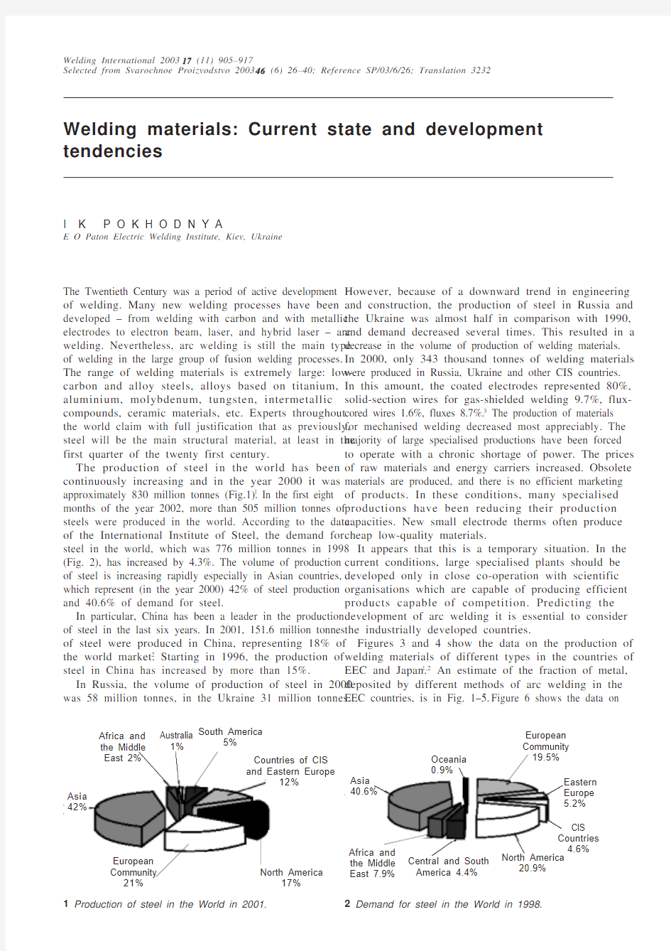
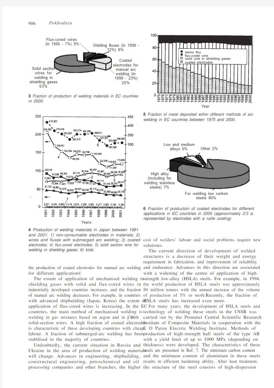
The production of steel in the world has been continuously increasing and in the year 2000 it was approximately 830 million tonnes (Fig.1).1 In the first eight months of the year 2002, more than 505 million tonnes of steels were produced in the world. According to the data of the International Institute of Steel, the demand for steel in the world, which was 776 million tonnes in 1998(Fig. 2), has increased by 4.3%. The volume of production of steel is increasing rapidly especially in Asian countries,which represent (in the year 2000) 42% of steel production and 40.6% of demand for steel.
In particular, China has been a leader in the production of steel in the last six years. In 2001, 151.6 million tonnes of steel were produced in China, representing 18% of the world market.2 Starting in 1996, the production of steel in China has increased by more than 15%.
In Russia, the volume of production of steel in 2000was 58 million tonnes, in the Ukraine 31 million tonnes.
However, because of a downward trend in engineering and construction, the production of steel in Russia and the Ukraine was almost half in comparison with 1990,and demand decreased several times. This resulted in a decrease in the volume of production of welding materials.In 2000, only 343 thousand tonnes of welding materials were produced in Russia, Ukraine and other CIS countries.In this amount, the coated electrodes represented 80%,solid-section wires for gas-shielded welding 9.7%, flux-cored wires 1.6%, fluxes 8.7%.3 The production of materials for mechanised welding decreased most appreciably. The majority of large specialised productions have been forced to operate with a chronic shortage of power. The prices of raw materials and energy carriers increased. Obsolete materials are produced, and there is no efficient marketing of products. In these conditions, many specialised productions have been reducing their production capacities. New small electrode therms often produce cheap low-quality materials.
It appears that this is a temporary situation. In the current conditions, large specialised plants should be developed only in close co-operation with scientific organisations which are capable of producing efficient products capable of competition. Predicting the development of arc welding it is essential to consider the industrially developed countries.
Figures 3 and 4 show the data on the production of welding materials of different types in the countries of EEC and Japan.1,2 An estimate of the fraction of metal,deposited by different methods of arc welding in the EEC countries, is in Fig. 1–5.1 Figure 6 shows the data on
Welding International 2003 17 (11) 905–917
Selected from Svarochnoe Proizvodstvo 2003 46 (6) 26–40; Reference SP/03/6/26; Translation 3232
Welding materials: Current state and development tendencies
I K P O K H O D N Y A
E O Paton Electric Welding Institute, Kiev, Ukraine
1 Production of steel in the World in 2001.
2 Demand for steel in the World in 1998.
European Asia 42%
Asia 40.6%
Oceania 0.9%
CIS Countries 4.6%
North America
20.9%
906Pokhodnya
the production of coated electrodes for manual arc welding for different applications.4
The extent of application of mechanised welding in shielding gases with solid and flux-cored wires in industrially developed countries increases, and the fraction of manual arc welding decreases. For example, in countries with advanced shipbuilding (Japan, Korea) the extent of application of flux-cored wires is increasing. In the EC countries, the main method of mechanised welding is welding in gas mixtures based on argon and in CO 2 with solid-section wires. A high fraction of coated electrodes is characteristic of these developing countries with cheap labour. A fraction of submerged-arc welding has been stabilised in the majority of countries.
Undoubtedly, the current situation in Russia and Ukraine in the area of production of welding materials will change. Advances in engineering, shipbuilding,constructural engineering, petrochemical and oil processing companies and other branches, the higher
cost of welders’ labour and social problems require new solutions.
The current direction of development of welded structures is a decrease of their weight and energy requirement in fabrication, and improvement of reliability and endurance. Advances in this direction are associated with a widening of the centre of application of high-strength low-alloy (HSLA) steels. For example, in 1994,the world production of HSLA steels was approximately 80 million tonnes with the annual increase of the volume of production of 5% or more.6 Recently, the fraction of HSLA steels has increased even more.
For many years, the development of HSLA steels and technology of welding these steels in the USSR was carried out by the Prometei Central Scientific Research Institute of Composite Materials in cooperation with the E O Paton Electric Welding Institute. Methods of production of high-strength hull steels of the type AB with a yield limit of up to 1000 MPa (depending on thickness) were developed. The characteristics of these steels are presented in Ref. 7. The minimum carbon content and the minimum content of aluminium in these steels results in efficient hardening ability. After heat treatment,the structure of the steel consists of high-dispersion
3
in 2000.
Solid section wires for welding in shielding gases
63%
Flux-cored wires (in 1998 - 7%) 9%
12%) 8%
4 Production of welding materials in Japan between 1991and 2001: 1) non-consumable electrodes in materials; 2)wires and fluxes with submerged arc welding; 3) coated electrodes; 4) flux-cored electrodes; 5) solid section wire for welding in shielding gases; 6) total.
electrodes for Years
P r o d u c t i o n o f w e l d i n g m a t e r i a l s , 103 t
applications in EC countries in 2000 (approximately 2/3 is represented by electrodes with a rutile coating).
High alloy (including for welding stainless
steels) 7%
907
Welding materials sorbie with solid-solution hardening of the ferritic matrix.This results in high strength, ductility and good weldability. Figures 7 and 8 generalise the data of advances in the metallurgy and technology of welding HSLA steels.In the USSR and subsequently in Russia and the Ukraine,the content of hydrogen, sulphur and oxygen in the metal of welded joints was greatly reduced, mechanical properties improved, weldability was increased and preheat temperatures reduced.
The data on the content of impurities in the currently produced HSLA steels are presented in Table 1.
The main tendencies of the optimisation of properties of HSLA steels are a decrease in the content of alloying elements; an increase in the number of combinations of microalloying elements; a decrease in the content of carbon, hydrogen, nitrogen, oxygen, residual elements,sulphur and phosphorus; improvement of the homogeneity and the level of mechanical properties and
improvement of the formability, weldability and toughness of welded joints.
These tendencies must be taken into account in the development of welding materials and welding technologies.
Welding of HSLA steels
The most important problem in welding HSLA steels is to prevent brittle fracture of welded joints. Brittle fracture is caused by structural transformations in the welded joint and the heat-affected zone (HAZ) and also by the embrittling effect of impurities dissolved in the metal, in particular hydrogen, manifested in the form of hydrogen-induced cracks and delayed fracture of welded joints.To prevent these phenomena, the advanced welding technologies used for steels of this type are based on preheating of components and heating during welding.These operations are energy- and labour-intensive (Fig.9), require high technological culture of production and are not really efficient. Because of the high temperature of the structures, resulting from preheating, the operating conditions of workers working in assembling operations and of welders are greatly impaired.
The fabrication of structures from HSLA steels without preheating is one of the main problems of arc welding at present. The results of investigations into the problem of hydrogen welded joints have been generalised in Refs.8–17. It should be stressed that when this problem, which is very important for all methods of consumable-electrode arc welding, must be taken into account when developing welding materials.
The preheat temperature of structures depends on the content of diffusible hydrogen in the weld metal, carbon equivalent P st and heat input in welding (Fig. 10).
7 Mechanical properties of welded joints in HSLA steels.
I m p a c t t o u g h n e s s , J /c m 2
Years
(prediction)
M a x i m u m y i e l d l i m i t , M P a
8 Content of impurities in welded joints in HSLA steels.
[H], cm 3/100 g
Years (prediction)
l e v e L S P N O H
H d n a O ,N )
l a t o t (%
.
m .p .p y
t i l a u q l a m r o N )t n e i c i f f e y l l a c i m o n o c e (s l e e t s n a e l C <500.0<200.0<010.0<500.00604040121<052<0
21Table 1
Years
908Pokhodnya
In steels and welded joints, the transfer of hydrogen is determined by its diffusion in fields of the gradient of concentrations and stresses, thermal diffusion, surface diffusion, diffusion through structural defects, and dislocations. The distribution of hydrogen in the welded joint in the presence of a stress concentrator were carried out by N. Yurioka (Fig. 11). It may be seen that the distribution of hydrogen in the welded joint is not uniform,and its content in the HAZ and at the fusion line is higher.
9 Required preheat temperature of the parent metal and the cost of welding operations (dark-grey – welding with preheating;grey – baking at 40–50 °C; light – welding without preheating 7).
10 Dependence of preheat temperature required for preventing cracking in welding steel with a yield limit of 460MPa on the diffusable hydrogen content in the weld metal:1) welding under a flux with a heat input of 3.0 kJ/mm, P st =0.235; 2,3) welding with coated electrodes with heat input of 1.7 kJ/mm, P st = 0.235 and 1.7 kJ/mm, P st = 0.212,respectively.8
Comment: Diffusible hydrogen content should not be higher than 2 cm 3 per 100 g of deposited metal
C r i t i c a l p r e h e a t t e m p e r a t u r e , °C
11 Distribution of hydrogen concentration in the weld metal at HAZ 5 hours after welding without preheating.8
12 Distribution of hydrogen across the joint line for weld metal at HAZ of different chemical composition.
Diffusible hydrogen content in
weld metal, ml/100 g
Distance from weld axis, cm
a
b
Welded joint
Hydrogen concentration, mm/100 g · atm 1/2
Welded joint
Fusion line
Fusion line
Hydrogen concentration, mm/100 g · atm 1/2
Distance from weld axis, cm
Yield limit,MPa Temperature of parent metal, °C at a thickness of
welded component, mm
C o s t o f w e l d i n g o p e r a t i o n s , %
909
Welding materials
The nature of distribution of hydrogen depends on the ratio of the temperatures of the start of martensitic transformation in the metal of the welded joint Ms wm and Ms HAZ (Fig. 12).
At Ms wm > Ms HAZ martensite forms earlier in the weld metal than in the HAZ, and the latter becomes a barrier for the transport of hydrogen and is characterised by a high concentration of diffusible hydrogen and by the development of potential conditions for crack formation (Fig. 12a ).
At Ms wm < Ms HAZ , martensite forms earlier in the HAZ than in the weld metal (Fig. 12b ) where the concentration of diffusible hydrogen is higher and is characterised by the formation of potential conditions for cracking.10
Diffusion of hydrogen in the weld metal depends on its chemical composition, structure, the presence of defects in the form of pores and non-metallic inclusions. The data on the mass transfer of hydrogen in the weld metal is presented in Fig. 13.
The rate of mass transfer of hydrogen in the welded joint produced with electrodes with a basic coating is several times higher than when welding with rutile-coated electrodes. This is associated with the presence of a large number of the so-called hydrogen traps – non-metallic inclusions and small pores in welded joints, welded with rutile electrodes.
Hydrogen ‘traps’ may also form in metal during its deformation. With an increase in the number of defects in the metal, the rate of mass transfer decreases.11
The content of diffusible hydrogen in the weld metal may be reduced as a result of microalloying with rare-earth metals (REM) and hydride-forming elements. Figure 14 shows the data on the effect of REM and yttrium on
the diffusible hydrogen content. The introduction of REM is accompanied by the redistribution of oxygen in the welded joint – the content of diffusible hydrogen decreases whereas that of residual hydrogen increases.Oxysulphides, formed during microalloying the weld with REM, accumulate hydrogen.
The redistribution of hydrogen in the weld metal may take place during phase transformations and depends on the cooling rate. The role of ‘traps’ is played by retained austenite in the weld metal (Fig. 15).18
Capture of hydrogen in ‘traps’ is explained by the low rate of mass transfer of hydrogen in retained austenite.In the presence of retained austenite in the welded joint,
13 Temperature dependence of the diffusion coefficient of hydrogen in the metal, deposited with basic (1) and rutile (2)electrodes, and the constants of the rate of generation of hydrogen from traps a metal deposited with rutile electrodes
Temperature, °C
Hydrogen diffusion coefficient, 10–5 cm 2/s
1000/Temperature, K –1
14 Dependence of the content of diffusable hydrogen in the weld metal on the content of REM (a ) and yttrium (b )10,11:b (welding in a temperature of 0.1% H 2+ Ar).
b
a
Basic variant
(0%)
D i f f u s a b l e h y d r o g e n c o n t e n t m l /100 g
[H], ml/100 g
[H]diff
Total REM content in electrode
coating, %
[H]res
15 Thermal desorption analysis of the redistribution of hydrogen in the metal of welded joints in HSLA steels in various transformations:18 1,2) cooling in air and in liquid nitrogen, respectively.
Peak of retained
austenite
Temperature, °C
G e n e r a t i o n o f h y d r o g e n ,p .p .m .
.
2.2 2.3 2.4 2.5 2.6
2.7 2.8 2.93
910Pokhodnya
standard measurements of the diffusible hydrogen content at a temperature of up to 250 °C show that the amount of hydrogen is lower. This must be taken into account when predicting the formation of hydrogen-induced cracks in welded joints.
The hydrogen content of welded joints depends mainly on the content of moisture and hydrogen-containing substances in electrode coatings, fluxes, cores of flux-cored wires, etc. In the development of welding materials with an ultra low hydrogen content it is important to consider the hydrogen content in wires and parent metal. To decrease the hydrogen content of initial and completed welding materials, it is recommended to apply heat treatment of electrodes and fluxes, with drying of shielding gases. Methods of decreasing the hydroscopic complicity of coatings and vacuum packing of electrodes have been developed. In materials for welding high strength steels, the content of potential hydrogen must be minimised. The baking temperature of electrodes is restricted at 450°C. A further increase of temperature results in the dissociation of components of the coating. In mixtures of minerals, the temperatures of the start of dissociation may be lower than in the initial minerals.
The minerals and impurities in them, and slags may bring in large quantities of hydrogen. The dry residue of water glass is an important source of hydrogen. Regulating the modulus and viscosity of water glass, it is possible to greatly reduce the potential content of hydrogen in the electrode coating (flux). A large amount of hydrogen is released from minerals at temperatures exceeding the baking temperature of electrodes and fluxes. In these cases, to reduce the hydrogen content of the welded joint, it is necessary to use metallurgical methods based on the bonding of hydrogen in the arc atmosphere into hydroxide OH and hydrogen fluoride HF, insoluble in liquid steel. Calculations show that the introduction of carbon tetrafluoride SiF
4
into the gas phase is more efficient than the introduction of molecular oxygen. SiF
4 forms in introduction series of CaF
2
with SiO
2
. Calculated values of the partial pressure SiF
4
for the CF
2
–SiO
2
system and experimental values of the hydrogen content in the metal, deposited with electrodes with different amounts of CaF
2
and SiO
2
in the coating are shown in Fig. 16. The correlation between the partial pressure of SiF
4
and the hydrogen content is good. The hydrogen content may be reduced even more efficiently by introducing silicon fluorides into the coating (flux) and the core of the flux-cored wire.
Calculations of the degree of association of OH and HF groups in arc discharges show that the efficient bonding of hydrogen by fluoride and oxygen makes it possible only at relatively low temperatures at the periphery of the arc column (Fig. 17). The effective temperatures for HF were not higher than 3000 K, and for OH they did not exceed 2500 K. The HF and OH were completely dissociated in a large part of the cross-section of the arc column.
Materials for welding HSLA steels
The elemental composition of the weld metal is usually selected on the basis of the requirements to produce full strength welded joints. The most important task is to ensure high cold resistance of weld metals at temperatures of up to –60 °C. Several alloying systems of the weld metal have been developed: Cr–Ni–Mn–Cu–Mo; Mn–Ni–Ti and Mn–Ni–Mo–Ti. The concentrations of these elements depend on the required strength and ductility
16 Calculated values of the partial pressure of silicon tetrafluoride in the arc atmosphere and the experimental values of the hydrogen content in the deposited metal: 1)
4% SiO
2; 2) 11%.
P
SiF4
, kPa
17 Dependence of the degree of dissociation with HF and
OH on the radius of the arc column r at a increased and b
lower temperature at the arc axis.
[H], cm3/100 g
b
a
911 Welding materials
of the welded joint. The materials are microalloyed with boron and titanium. A welding wire with very low sulphur and hydrogen contents has been developed: 0.01–0.02% S and P, 0.04–0.08% C. The content of alloying elements and deoxidation agents, and also the welding conditions must be selected to ensure that the oxygen content of the weld metal is in the range 0.02–0.04%. The titanium oxides, formed during this process, for example, TiO, are the centres of nucleation of ferrite needles.19 The structure with a secure ferrite is favourable from the viewpoint of producing weld metals with sufficiently high toughness at low temperatures.
The relationship of the chemical composition, structure and properties of weld metals in HSLA steels has been studied in detail in Ref. 20 and 21. The characteristics of several electrodes were published in Ref. 22, 39–43.
Welding is carried out using high-basicity agglomerated fluxes and electrodes with basic coatings. In welding HSLA steels with a carbon content of 0.1–0.2% components must be preheated. In both cases, hydrogen-induced cracks are found in the HAZ. The problem of production of welded joints with no cracking has been tackled by developing steels with very low carbon content (up to 0.02%) and with higher alloying degrees. In welding structures made of these steels, hydrogen-induced cold cracks form in the weld metal. The solution of these problems is associated with the development of reliable methods of controlling the hydrogen content of welded joints.
The results of fundamental investigations of reversible hydrogen brittleness (RHB) were carried out recently at the E O Paton Electric Welding Institute15–17 and were used in determining the mechanism of RHB on the atomic level.
The directions of further investigations may be formulated as follows:
?examination of heterophase interactions taking place during heating and melting of electrodes, fluxes, flux-cored wires;
? a decrease in the hydrogen content of welded joints as
a result of decreasing the content of hydrogen com-
pounds in flux systems and control of plasma chemical reactions in the arc atmosphere;
?increasing the hydrogen embrittlement resistance of the weld metal and the HAZ;
?physical and mathematical modelling of the behaviour of hydrogen in welded joints;
?determination of the parameters of the state of welded joints, preventing the formation of cold cracks, includ-ing the formation of hydrogen ‘traps’ in the weld metal for decreasing the diffusible hydrogen content and re-stricting its mass transfer from the weld metal into HAZ;?development of scientific fundamentals of producing welded joints and in welds with high strength, plastic-ity and impact toughness;
?improvement of equipment and technology of the pro-duction of high quality welding materials for general and special applications.General purpose electrodes
The main bulk of steels used in industry and engineering of the CIS countries is represented by the low carbon and low-alloy steels and the proportion of general purpose electrodes with rutile and ilmenit coatings is approximately 80% of produced electrodes. It should be mentioned that the mechanical properties of welded joints, produced with these electrodes, satisfy in most cases the requirements of domestic European and American standards. They should be improved in the direction of increasing the stability of arcing, weld formation, separation of the slag skin, and preventing the formation of pores and hot cracks. These problems have been studied in detail in Ref. 23. The introduction of easily ionised elements into the coatings increases the concentration of positive ions in the peripheral region of the arc and decreases arc constriction and the work function of electrodes from the cathode. In this case, the required density of the electron flux may be achieved at lower values of the strength of the electric field and the cathode.
Separation of the slag crust is controlled by the process of interaction of the slag with the solidified metal of the weld pool. The metal-slag boundary is characterised by the formation of a thin interlayer consisting of non-stoichiometric oxides or spinals. If the parameters of the crystal lattice of these compounds are close to the parameters of the metal lattice, the chemical bonding and epitaxial growth of the flux phase take place and the separation of the slag is impaired. This process can be regulated by changing the activity of oxygen in the slag. In the case of pore formation of the welded joint and presence of undercutting, mechanical wedging of the slag takes place and its separation efficiency is reduced.
The problems of porosity have been examined in detail in Ref. 24. It has been shown that the porosity of weld metals in welding with electrodes of this type is caused by the hydrogen dissolved in the weld pool. The concentration of hydrogen in the weld pool is considerably higher than the equilibrium value. Therefore, the formation of pores can be prevented in this case only by regulating the interfacial tension at the metal–gas boundary. It is efficient to increase the oxidation potential of the metal. It is thus possible to reduce the probability of nucleation of gas bubbles. The second method is the controlled rate of growth of hydrogen bubbles as a result of decreasing the silicon content of the weld pool.
In most cases, the formation of hot (solidification) cracks in the welded joints is associated with an increase of the carbon and sulphur content of the weld pool.25 A source of sulphur is the parent metal, welding wire and coating components. Domestic standard steels contain a considerably higher sulphur content than foreign ones. This also relates to welding wires. The formation of hot cracks in the welded joints can be prevented by increasing the manganese content of the deposited metal to 0.6–0.8%.
The electrodes with a basic coating are used for welding important structures made of steel of different type. The problems of improving the welding and technological
912Pokhodnya
properties of electrodes and mechanical properties of welded joints have been examined previously.
The ‘starting’ porosity of welded joints is one of the serious defects in welding with basic-coated electrodes.The experimental results show that it is associated with the absorption of nitrogen by electrode metal droplets and by the weld pool. In welding under basic slags,containing fluorine compounds, the molten metal of the droplet in the pool is inefficiently protected by the slag and is in direct contact with the arc discharge plasma. In the thermodynamic equilibrium conditions, the dissociation of gas molecules at the metal surface is a limiting member of the absorption process. In absorption of gases from arc discharge plasma the degree of dissociation of gases is determined by the plasma temperature. It has been shown that the heat content of the electrode metal droplets depends on current and its polarity (Fig. 18). In many cases, the droplet temperature exceeds the temperature of maximum solubility of gases in iron.
Therefore, the difference in the temperatures of the droplets of 200–300 K in consumable electrodes welding with straight and reverse polarity may have a significant effect on gas absorption. The higher concentration of gases in the metal in welding with straight polarity and alternating current, observed in practice, confirm this assumption.
The absorption of nitrogen depends on arc length. A decrease in arc length as a result of the deposition of electrically conducting compositions on the end of the electrode, and sharpening of the electrode tip make it possible to reduce the arc length in separation of the
electrode during its ignition. A decrease in the degree of nitrogen absorbing may be achieved by reducing the interfacial tension at the slag–metal boundary in order to improve the efficiency of slag shielding in the molten metal in the droplet and pool stages, increase the droplet temperature and ensure fine-droplet or spray transfer of metal as a result of transition from the arc discharge gases to vapour–gas discharges. The same phenomena were observed in the interaction of metal with hydrogen. The physico–chemical aspects of this process were examined previously.
The most important problems, requiring solution in the development of electrodes with a basic coating, are the improvement of the welding and technological properties; increase of the impact toughness of welded joints as a result of decreasing the content of harmful impurities and microalloying and a decrease in the hydrogen content in the weld metal by preventing the aborption of moisture as a result of the application of non-hygroscopic types of starting material, the use of high-modulus low-viscosity water glass, optimisation of baking temperature and ensuring uniform temperature and moisture content in drying–baking systems.18 Dependence of the content of electrode metal droplets on current in welding with 1 straight 2 reversed polarity with Sv-08A wire, diameter 2 mm, in the atmosphere of a He+N 2and b Ar+N 2 (cross-hatched areas are the regions of temperature current resulting in the maximum solubility of nitrogen and low carbon steel).24
a
b
S k , cal/g
S k , cal/g
I w , %
I w , %
Labour hygiene characteristics of electrodes Investigations aimed at improving the hygiene characteristics of electrodes are very important. The studies contacted at the E O Paton Electric Welding Institute in cooperation with labour hygiene experts,toxicologists, chemists and biophysicists have been generalised in Ref. 26. The main results of these investigations may be formulated as follows:27
?the main toxic ingredient in fusion welding is the solid component of welding fumes (SCWF);
?SCWF forms as a result of the evaporation of metallic slag melts, with elements with high vapour elasticity characterised by a very high evaporation rate;
?in melting electrodes with rutile or ilmenit coatings, the evaporation of manganese from the metallic melt is more intensive than from the slag melt;
?
evaporation of elements and compounds from the slag depends on its basicity and with increasing basicity the rate of evaporation of compounds of alkaline and alkaline-earth metals rapidly increases;
?
the labour hygiene characteristics of electrodes with rutile or ilemenit coatings may be improved by decreas-ing the basicity of the slag and interfacial tension of the metal–slag interface;
?
superjating of the droplets of the electrode metal, the weld pool and the slag increases the amount of the SCWF, and the temperature of the molten metal and slag may be reduced by increasing the coefficient with the mass of the coating and by introducing a large amount of iron powder into the coating;
?
in melting electrodes with a basic coating, in addition to the evaporation of manganese (chromium), the gas component of the welding fume is also very important.
913
Welding materials
This component consists of fluorine compounds of al-
kaline and alkaline-earth metals and also HF and SiF
4;
the generation of these gases can be regulated by con-trolling the activity of silicon oxide in the slag and the content of moisture in the coating;
?maximum threshold values for SCWF were determined disregarding the special features of the structure, com-position and size of the particles of the SCWF; the com-bined effect on the organism of the group of elements or complex compounds may weaken or enhance the ef-fect of the most toxic components of the welding fumes;?it is necessary to continue and intensify work in the modelling and prediction of the biological effect of SCWF on the human organism taking into account the results of detailed investigations carried out in the Eighties and Nineties.
Welding wires
Solid-section wires
Steel welding wires are used for the production of coated electrodes, mechanised arc welding in shielding gases and submerged-arc welding, electroslag welding and as filler rods in TIG welding.
Steel for wires is melted in oxygen converters, open-hearth and electric arc furnaces, and cast either into ingots or billets. The steel for producing wires is often subjected to special treatments to decrease the content of harmful impurities, non-metallic inclusions and for degassing the metal. The ingots (billets) are ruled by conventional technology. Rolled wire is cold-deformed by drawing. The requirements on wire are controlled by the GOST 2246-70 standard which is now quite obsolete.
To improve the composition of solid-section wires in order to improve welding, technological and metallurgical characteristics of the welding process and improve the properties of welded joints, it is essential to reduce the content of harmful impurities (S, P, As, Sb, etc.): carry out microalloying with Ti, Zr, B, REM and other elements; decrease the carbon content in a number of grades of high-alloy wires, optimise the alloying system, reduce the gas content of the wire, improve the homogeneity of the billets and reduce the permissible deviations of the content of elements of phenomenal composition. It is preferred to use billets produced from converter steel in continuous casting installations. It is essential to improve the technology of melting steel and of its further treatment.
It is important to ensure high plasticity of components for increasing the reliability of the drawing process, the required mechanical properties of wires, high quality and clean surfaces without tears or scratches, absence of ovality and the minimum deviation of the dimensions from the given nominal value.quantities in a number of industrial and engineering companies.
The level of development has been sufficiently high, as indicated by a large number of author’s certificates and patents, and also by the sales of licences and organisation of production in a number of countries: USA, Germany, France, Japan, Hungary, Bulgaria, Czechoslovakia, etc. The characteristics of these wires and special features of welding technology are presented in a catalogue in Ref. 28.
The downward trend in the economy in the Nineties resulted in a decrease in the volume of production. At present, flux-cored wires are produced in obsolete systems in companies Severstal’ in Russia and Dneprometiz in the Ukraine. This equipment is used with progressive wear. Wires developed in the Seventies and Eighties are produced. At the same time, this efficient direction of welding technology is successfully being developed in the USA, Japan, France, Germany, South Korea, Sweden, Holland, Austria, etc. New grades of wires have been developed, ranges of application expanded, and equipment and technology improved. For example, the companies Lincoln Electric, Hobart, ESAB, S.A.F.-Oerlikon, Thyssen-Bohler, Kobelko, Elga, etc. produce and advertise flux-cored wires of tens of grades for welding in CO
2
and Ar + CO
2
mixtures, and also self-shielding wires for submerged-arc welding. These are wires for welding low carbon, low-alloy, heat resistant, high strength, creep resisting and corrosion resisting steels, used in shipbuilding, engineering, power engineering, mining industry, constructional engineering and other branches.29–33
It should be mentioned that in these years the flux-cored wires were developed in a number of organisations in the Ukraine and Russia, in particular, E O Paton Electric Welding Institute – flux-cored wires of a new generation in accordance with European standards EN 758 and GOST 26271.34
The wires developed for welding carbon and low alloy steels for mass applications include wires PP-AN59, PP-AN3, PP-AN69, and also welding low-alloy steels PP-AN61 and PP-AN67. These wires are of tubular design with a diameter from 1.2 to 2 mm. The mechanical properties of the weld metal, produced with these flux-cored wires, are presented in Table 2, the mechanical composition of the weld metal is in Table 3.
Welding with new wires is characterised by efficient weld formation and a small amount of splashes and welding film. Melting of PP-AN59 and PP-AN63 wires with a rutile coating is characterised by the formation of rapidly hardening short slag. The wires are suitable for welding in all spatial positions. PP-AN70 wire with a metallic core has been developed for alternated and robotised welding in shipbuilding and engineering. Its productivity is 20% higher than that of solid section wires of the same diameter. The shielding gas is SO
2
or a mixture of Ar + CO
2
. The welding and processing properties of the PP-AN70 wires are considerably higher than those of Sv-08G2S wire.
The E O Paton Electric Welding Institute has developed self-shielding flux-cored wires with a fluoride-basic core.35
Flux-cored wires
The industrial production of flux-cored wires in the USSR started in the Fifties and Sixties and has been developed rapidly since then. Flux-cored wires are used in large
914
Pokhodnya
The composition of the core makes it possible to reduce the silicon and aluminium content of the weld metal and ensure the required impact toughness of welded joints at lower temperatures.
At present, the Prometei Central Scientific Research Institute of Composite Materials is working on the development of gas-shielding flux-cored wire 48-PP-8N,48-PP-11R and 48-PP-12R with a diameter of 1.2–1.6 mm for welding low carbon HSLA steel with a yield limit from 400 to 620 MPa.36 Experimental–industrial verification of technology of welding these wires in shipbuilding plants is being carried out. Work is being conducted to improve the technology of production of wires.
The Central Scientific Research Institute of Assembling Operations have developed self-shielding flux-cored wires for welding in all spatial positions with a yield limit of the weld metal of up to 490 MPa.37
Advanced hyperactivity equipment and production technologies are very important in the development and production of small diameter flux-cored wires.
Recently, a method of production of flux-cored wires by the rolling-drawing methods has been recommended.The thin layer of drawing lubricant, remaining on the surface of the wires, does not introduce large quantities of hydrogen into the arc atmosphere and results in efficient feed of the wires with flexible hoses in mechanised welding.
The E O Paton Electric Welding Institute together with OZSM IES and the heavy engineering works (Almaty)have developed advanced equipment and technology for the fabrication of flux-cored small diameter wires.Equipment for basic operations is fitted with advanced means of objective control, documentation and diagnostics.38 New equipment has been supplied to
Chinese companies. The design productivity of a single line is 1000 t per annum. In Chinese companies, the productivity limit has been exceeded 1.5 times.
Technology and equipment have been developed for the production of flux-cored wires with a diameter of 9–13 mm for injection metallurgy. Industrial production of these wires has been set up at the Arksel Company and at the E O Paton Electric Welding Institute. In recent years, this technology has been used at Azovstal’Company and other plants to process millions of tonnes of steels for different applications. This has resulted in a large improvement of quality. The majority of steel grades have been certified.
Thus, the plants in the Ukraine and Russia have the required facilities for producing advanced flux-cored wires.What is required is the serious analysis of the market and appropriate financing of this project.Welding fluxes
Submerged-arc welding, developed at the E O Paton Electric Welding Institute is used widely in shipbuilding,engineering, in bridge construction, fabrication of engineering metal structures and in many other applications. A higher level of scientific investigations,efficient solutions, efficiently organised industrial production, and also the low cost of energy carriers have resulted in the mass production of cheap high quality fused fluxes. As regards to the volume of production of fused fluxes, the USSR occupied the leading position in the world. The application of submerged-arc welding resulted in mass transformations in many areas of industry and construction.
The production of welding fluxes in developed countries
e
r i W ,t i m i l d l e i Y a P M e l i s n e t e t a m i t l U a P M ,h t g n e r t s e
v i t a l e R %,n o i t a g n o l e e
r u t a r e p m e T t c a p m i n i g n i t l u s e r f o l e v e l s s e n h g u o t m /J 74(2C °)s
c i t s i r e t c a r a h c g a l S 95N A –P P 36N A –P P 96N A –P P 16N A –P P 76N A –P P 0240240240640
65006–055065–025045–015036–0550
67–00782–4292–5233–8252–320
2–8102–02–03–04–0
3–)R (e s a b e l i t u r g n i y f i d i l o s y l d i p a R e v o b a s A )
B (c i s a B )R (e s a b e l i t u R )
B (c i s a B e
r i W %
,l a t e m d e t i s o p e d n i s t n e m e l e f o t n e t n o C ,t n e t n o c n e g o r d y H n i g 001/l m l a t e m d e t i s o p e d C
n M i S i N r C o M 95N A –P P 36N A –P P 96N A –P P 16N A –P P 7
6N A –P P 80.0–50.070.0–40.090.0–70.070.0–30.09
0.0–40.05.1–1.16.1–2.15.1–3.15.1–1.13
.1–1.16.0–3.05.0–3.04.0–3.05.0–3.04
.0–3.06.0–4.0––
7.1–3.13
.1–1.1––––
4
.0–2.0––––
4
.0–2.08–58–57–45–35
–3Table 2
Table 3
915 Welding materials
has now been stabilised. The production of materials for submerged-arc welding represents 5–10% of the total volume of production of welding. The metallurgical and technological special features of submerged-arc welding have been described in many specialised publicat-ions.25,44–48
A decrease in the demand for steel resulted in a large reduction in the volume of production of fused fluxes, mainly in electric furnaces.
Studies carried out in recent years have been concerned with a decrease of the content of harmful impurities in fluxes, the search for advanced flux–wire systems resulting in the required mechanical properties of welded joints, and in a decrease of the level of hydrogen content in fluxes.48–50
As mentioned, the volume of production of HSLA steels is increasing throughout the world. Stringent requirements of the mechanical properties of welded joints are difficult to satisfy using used fluxes. The results of investigations show that, when welding HSLA steel of the type 12KhN2MDF with a alloyed wire produced by vacuum induction melting under a fused flux FIMS-20P (this steel is used for producing important structures operating in offshore platforms), the required level of impact toughness is obtained only at –20 °C, and when welding under an agglomerated flux at –60 °C.54 In Western European countries fused fluxes have been gradually replaced in the last couple of decades with agglomerated fluxes which now represent 95% of the volume of welding fluxes used.53
This is determined by the metallurgical possibilities of agglomerated fluxes (regulation of the silicon-reduction process, refining and microalloying of the weld pool, high strength and impact toughness of welded joints), by a large decrease of the energy requirement of production, and also by smaller harmful emission of toxic dust and gas into the atmosphere. Information on the currently available agglomerated fluxes and also on technology of producing these fluxes have been published in Ref. 55–56.
Because of the development of production of advanced pipes, shipbuilding, energy and chemical engineering, and the construction of bridges in the Ukraine, the volume of application of HSLA steels will undoubtedly increase. It is already necessary to develop prototypes of equipment and technology of production of these fluxes, certify the products, carry out marketing and organised export of the products.
Welding belongs to special technological processes in which the quality of production cannot be reliably confirmed by direct tests in final (despatch–reception) inspection and must be ensured in accordance with the requirements of the currently valid international standards in the process of fabrication by adhering to the required conditions, applications of prescribed materials and the employment of highly qualified personnel. Thus, the efforts of investigators and developers must be concentrated to finding new types of starting materials and the development of new welding materials:?general purpose electrodes with rutile and ilmenit coat-
ings with excellent welding–processing and labour safety properties;
?electrodes of a new generation for welding HSLA steels for shipbuilding, engineering and construction indus-tries;
?general purpose electrodes with basic coatings ensur-ing impact toughness of welded joints not lower than
60 J/m2 at a test temperature of –60 °C;?electrodes for welding assembling joints in transmis-sion pipelines;
?wires and laminated fluxes for welding high strength low alloy steels with a yield limit of up to 800 MPa;?flux-cored wires with rutile and basic cores and wires with a metallic small diameter core for gas shielding welding in all spatial positions;
?universal self-shielding flux-cored wire;
?special welding materials for different applications.
Preference should be given to investigations and development of new hyperactivity equipment and technologies for producing welding materials, systems of analytical control and regulation of the quality of products.
Tendency in the development of welding production and welding materials
In the first decade of the Twenty First Century, steel will remain the main structural material. As previously, low carbon and low alloy steels will be used on a large scale. Their quality, mechanical properties and weldability will be improved as a result of decreasing the content of harmful impurities, finding new alloying systems, heat treatment, increasing corrosion resistance in different media. Special attention will be given to the development of new types of high strength low alloy steels, including those with a very low carbon content, heat resisting steels, steels of structures operating at low climatic temperatures, cryogenic applications and high alloy steels for different purposes.
Further work will be carried on the development of aluminium high strength alloys, alloyed titanium alloys and other types of new structural materials.
As previously, arc welding will occupy the most important position in the group of fusion welding processes. The advances in the development and production of welding materials will be closely linked to the tendencies in the development of structural materials. Main solutions in the area of development of new welding materials will be associated with optimisation of the systems of alloying the weld metal in relation to the structure and properties of the parent metal, methods of decreasing the high content of hydrogen, nitrogen and other harmful impurities in the weld metal, the development of effective technologies and materials for increasing the strength and ductility of welded joints, decreasing preheat temperature, preventing the formation of different cracks, including those induced by hydrogen. New slag
916Pokhodnya
systems of the cores of flux-cored wires, electrode coatings and fluxes will be developed.
Further work will be carried out in improvement of the metallurgical and welding–technological properties of electrodes, fluxes, solid section wires and flux-cored wires, shielding gases in order to decrease porosity, to prevent hot cracking, improve penetration, the shape of welded joints, separation of the slag crust, the stability of arcing and decrease the degree of splashing.
The mathematical and physical method of modelling the main metallurgical processes of arc welding will be developed further. Computerised databases and knowledge bases and expert systems for welding materials will be developed.
In industrially developed countries, work will be carried out to decrease the fraction of coated electrodes in the general volume of the production of welding materials and the fraction of wire for welding in solid gases with a solid section and, in particular, flux-cored wires (with flux and metallic cores) will be decreased, whereas the fraction of production of welding fluxes is expected to remain unchanged.
As previously, coated-electrode arc welding will be used on an increasing scale in the developing countries.
One priority will be a decrease in the material and energy requirement of welding materials both in the process of production and application. Special attention will be given to the development of production of universal gas shielding flux-cored wires of small diameter and agglomerated fluxes, efficient in welding very important structures, and also electrodes, fluxes and wires in absorption of moisture ensuring efficient reignition of the arc, easy supply in automatic and semi-automatic welding equipment, and minimum penetration of welding fume.
It is important to mention the improvement and increase of the reliability of equipment and production technology of welding materials, the supply of starting materials with stable quality, automation of analytical inspection and technological facilities of production. The quality of welding materials and their appearance, packing and transport will be improved. The preparation of experts of different specialisations will be improved, i.e. investigators and developers of welding materials, and also technologies-production engineering, highly qualified experts and personnel.
Improvement of the economic system and increased competition between Western and Eastern countries will greatly increase the rate of economic and technical transformations and will support the increase of the volume of production of welded structures and welding materials. References
1Doria J G: ‘Welding consumables: Market Trends’. European Welding Association Istanbul 20 2001.
2Tikhonov A: ‘World war of steel makers’. Izvestiya 2002 (169) 6.
3Ignatchenko P V and Bugai A I: ‘Current state of production of welding materials at the threshold of a new millenium: Arc welding. Materials and quality at the start of the 21st Cen-tury’. Publ Orel 2001 81–83.
4Nassau L V: ‘Export report stick electrodes 2000’. Stick elec-
trodes. European Welding Association Istanbul 2001 9.
5The Japan Welding News for the World. Autumn issue. 2001 5
(17) 10.
6Morrison W B: ‘Past and future development of HSLA steels’.
The 4th Int. Conf. HSLA’ steels 2001'’. Metallurgical Industry Press Xi’an 2000 11–19.
7Gorynin I V et al: ‘Prospects and problems of material science in the development of materials and welding technologies in the construction of unique ice-resistant platforms’. In: ‘Cur-rent material science, 21st Century,’. Pokhodin I K (ed). Publ Naukova dumka Kiev 1998 84–94.
8Yurioka N: ‘Hydrogen assisted cracking in C–Mn and low al-loy steel weldments’. International Materials Reviews 1990
35 (4) 217–249.
9Yurioka N: ‘Predictive methods for prevention and control of hydrogen assisted cold cracking’. IIW Doc. IX-1938-99 16. 10Maroef I et al: ‘Hydrogen cracking of welded components of high strength steel’. In: 'Welding and allied technologies in the 21st Century'. Publ E O Paton Electric Welding Institute Kiev 1998 166–176.
11Pokhodnya I K: ‘Problems of welding high strength low alloy steels’. In:‘Current material science, 21st Century,’. Publ Naukova dumka Kiev 1998 31–69.
12Shvachko V I et al: ‘The evaluation methods of HLSA steels susceptibility to hydrogen embrittlement’. HSLA Steels’ 2000.
Publ Metallurgy Industry Press Beijing 2000 453–458.
13Gedeon S A and Eagar T W: ‘Assessing hydrogen-assisted crack-ing fracture modes in high-strength steel weldments’. Welding Journal 1990 (6) 213.
14Gedeon S A and Eagar T W: ‘Thermomechanical analysis of hydrogen absorption in welding’. Welding Journal 1990 (7) 264.
15Pokhodnya I K et al: ‘Role of temperature in hydrogen crack-ing of structural steels and welded joints’. Avt Svarka 2000 (2) 3–8.
16Shvachko V I: ‘Hydrogen embrittlement of welded joints in structural steels’. Author's abstract of a dissertation for the title of doctor of physico–mathematical sciences, Khar'kov Physico–Technical Insitute of Khar'kov 2002 35.
17Stepanyuk S M: ‘Hydrogen embrittleness in welding high chro-mium low alloy steels’. Author's abstract of a dissertation for the title of doctor of physico–mathematical sciences, E O Paton Kiev 2001 18.
18Park Y D et al: ‘Retained austenite as a hydrogen trap in steels welds’. Welding Journal 2002 (2) 19–35.
19Abson D J: ‘Microstructure and mechanical properties of ver-tical-up C-Mn-Ni steel semi-automatic weld metal’. Welding Int. Research Report 1987 (7) 1–30.
20 Baryshnikov A P et al: ‘Welding of high strength cold resisting
steels in shielding gases with copper electrodes’. Advanced Materials and Technologies 1996 (2) 207–220.
21Malyshevsky V A et al: ‘Welding materials and technology of welding high strength steels’. V oprosy Materialovedeniya 1999
(3) 69–77.
22Gezha V V et al: ‘Methods of increasing welding and techno-logical characteristics of electrodes with basic coatings de-signed for welding high strength and cold resisting steels’.
Voprosy Materialovedeniya 2000 (1) 69–77.
23Pokhodnya I K: ‘Metallurgiya of welding, current state and problems’. In: 'Welding and allied technologies in the 21st Century'. E O Paton Electric Welding Institute Kiev 1998 227–245.
24Pokhodnya I K: 'Gases in welding joints’. Publ Mashinostroenie Moscow 1972 256.
25Frumin I I: ‘Automatic hard facing’. Publ Metallurgizdat Khar’kov 1961 421.
26Voitkevich V: ‘Welding Fumes’. Abington Publishing Special Report. Abington Publishing 1995 110.
27Yavdoshchin I R and Pokhodnya I K: ‘Formation of welding fumes in fusion welding and its labour safety evaluation’. In: 'Protection of the environment, health and safety in welding production'. Publ Astroprint Odessa 2002 38–56.
28Pokhodin I K (ed): ‘Flux-cored wires for electric arc welding',
a catalogue-handbook. Publ Naukova dumka Kiev 1980 180. 29Altemuhle B: ‘The use of rutile cored wires for welding high strength steel in crane fabrication’. Svetsaren 2000 (1) 33–
36.
30Ferree S E and Sierdzinski M S: ‘Stainless steel metal cored wires for welding automotive exhaust systems’. Svetsaren 2000
(3) 15–18.
31Blome K: ‘Filarc PZ 6105R. The robot-friendly cored wire’.
917 Welding materials
Svetsaren 2000 (1) 22–24.
32Farrow N and Studholme S: ‘Submerged arc welding with fused flux and basic cored wire for low-temperature applications’.
Svetsaren 2000 (1) 33–36.
33‘Fabshield 2125’. Welding Journal 1990 (7) 45–46.
34Shlepakov V N et al: 'Flux-cored wires with a new generation for welding in shielding gases’. In: 'Arc welding. Materials and quality at the start of the 21st Century'. Publ Orel 2001 57–
59.
35Naumeiko S M: ‘Regulating the welding and technological prop-erties of flux-cored wires using the results of physico-chemi-cal properties of slags’. In: 'Arc welding. materials and quality at the start of the 21st Century'. Publ Orel 2001 102–106. 36Baranov A V: ‘Problems of production and experience with the application into production of conditons of flux-cored wires of small diameter’. In: Arc welding. materials and qual-ity at the start of the 21st Century'. Publ Orel 2001 62–63. 37Moisov L P and Isaenko P R: ‘PPT-13 self-shielding flux-cored wire’. In: Arc welding. materials and quality at the start of the 21st Century'. Publ Orel 2001 61.
38Shlepakov V N: ‘Automated equipment for production of flux-cored wires’. In: Arc welding. materials and quality at the start of the 21st Century'. Publ Orel 2001 64–67.
39Pokhodnya I K et al: ‘ANO-TM electrodes for welding off-shore stationary platforms’. Tekhnologiya Sudostroeniya 1990
(9) 77–79.
40Yavdoshchin I R: ‘New electrodes developed at the E O Paton Electric Welding Institute for welding structures of low carbon and low alloy steels’. In: 'Current state and prospects of devel-opment of welding steels in CRS countries'. Publ Moscow 1998 135–137.
41Marchenko A E and Skorina N V: ‘E70-E85 type electrodes for welding high strength cold resistant steels’. In: 'Current state and prospects of development of welding steels in CRS countries'. Publ Moscow 1998 28–33.
42 Lobanov L M et al: ‘Economically alloyed electrodes E70-
E85 for welding high strength cold resistant steels’. In: 'Cur-rent state and prospects of development of welding steels in CRS countries'. Publ Moscow 1998 28–29.
43Malyshevsky V A et al: ‘Electrodes for welding structures operating at low temperatures, and the need for improvement of their technological properties’. In: 'Current state and pros-pects of development of welding steels in CRS countries'. Publ Moscow 1998 175–176.44Frumin I I et al: ‘Low silicon fluxes for automatic welding and surfacing’. Avt Svarka 1956 (1) 10–12.
45Lyubavsky K V: ‘Metallurgy of fusion welding, a welding hand-book’. Sokolova E V (ed). Publ Mashgiz Moscow 1960 1 51–138.
46 B E Paton (ed): ‘Welding fluxes and slags’. Publ Naukova
dumka Kiev 1974 164.
47Podgaetsky V V and Kuz’menko V G: ‘Welding slags’. Publ Naukova dumka Kiev 1988 252.
48Potapov N N: ‘Current state and prospects of development of flux production’. Svar Proiz 1997 (9) 34–36.
49Goncharov I A et al: ‘A flux restricting the hydrogen content of welded joints’. In: 'Current state and prospects of develop-ment of welding steels in CRS countries'. Publ Moscow 1988 164–167.
50Goncharov I A et al: ‘A new approach to preventing porosity in welding under fused fluxes’. In: 'Current state and prospects of development of welding steels in CRS countries'. Publ Mos-cow 1988 191.
51Kuz’menko V G: ‘Thermodynamic and structural assets of the composition of fluxes for electric welding’. Author's abstract of the dissertation for the title of candidate of doctor of tech-nical sciences, E O Paton Electric Welding Institute Kiev 2002 33.
52Goncharov I A: ‘Development of low-hydrogen welding fluxes of magnesium-silicate type’. Author's abstract of the disserta-tion for the title of candidate of doctor of sciences, E O Paton Electric Welding Institute Kiev 2002 18.
53Pokhodnya I K: ‘Welding and light processes at the Essen Exhibition. Welding materials’. Avt Svarka 2002 (1) 29–32. 54Pokhodnya I K et al: ‘The results of comparative tests of fused and ceramic fluxes using in welding 12KhN2MDF steel’.
Avt Svarka 1987 (11) 61–64,68.
55Pokhodnya I K and Golovko V V: ‘Fluxes for welding low alloy high strength steels developed at E O Paton Electric Welding Institute’. Svarshchik 1999 (1) 8–9.
56Baranov A V et al: ‘Agglomerated fluxes for automatic weld-ing of high strength and cold resistant steel and technology of production developed by Prometei at the Scientific Research Institute of Composite Materials: Arc welding, materials and quality at the start of the 21st Century’. Publ Orel 2001 109–110.
57Lakomsky V I: ‘Plasma arc remelting’. B E Paton (ed) Publ Tekhnika Kiev 1974 336.
激励机制设计的五个原则 建立激励机制必须要研究员工的需求,依照各种激励理论将不同的激励方法加以适当组合。只有对不同的情况区别对待,使用相应的激励手段,才能对企业团队和员工个人实施有效地激励。因此,民营企业要建立良好的人才激励机制,必须遵循物质激励与精神激励相结合、正激励与负激励相结合、长期激励与短期激励相结合、绩效原则、公平原则等基本原则,并且有所侧重,必须想方设法了解并满足员工多元化的个人心理需求,采取多种形式的激励手段,充分激发员工潜能,确保激励机制的合理性和实效性。 一、物质激励与精神激励相结合原则 从管理学上说,激励可分为两类:一类是物质激励,也叫薪酬激励;另一类是精神激励,又叫成长激励。物质激励与精神激励作为激励的两种不同类型,是相辅相承、缺一不可的,只强调物质激励而忽视精神激励或只强调精神激励而忽视物质激励都是片面和错误的。 在实际工作中,一些人总以为有钱才会有干劲,有实惠才能有热情,精神激励是水中月、镜中影,好看却不中用。正是这种片面的理解,致使一部分人斤斤计较、唯利是图,甚至弄虚作假、违法乱纪,给组织环境和社会风气都带来极大危害。另有一些人总爱把大道理挂在嘴边,只讲贡献不讲需要,只讲觉悟不讲利益,以为大家靠喝西北风也能有干劲,这些人恰恰忘了:“思想一旦离开利益,就一定会使自己出丑”。为了避免以上两种片面性的发生,防止“单打”现象的出现,在激励中一定要坚持物质激励与精神激励相结合的方针。 强调物质激励与精神激励相结合,并不是说不需要有所侧重,物质激励与精神激励是对人们物质需要和精神需要的满足,而人们的物质需要和精神需要在层次与程度上受多种因素的制约,并随主客观条件的发展而不断有所变化.从社会角度来看,一般来说,社会经济文化发展水平比较低,人们的物质需求就会比较强烈,而在社会经济文件发展水平比较高的条件下,人们的精神需要则会占主导地位。从个人角度来看,一个人受教育的程度、所从事的工作性质及其自身的品德修养也会对需要产生很大程度的影响。所以,不论从个人发展还是从社会发展
虚拟演播室是视频技术于计算机技术结合的产物,把计算机图形图像处理技术与传统的色键技术集合起来形成的。是一种新颖的独特的电视节目制作技术。 虚拟演播室技术原理:虚拟演播室技术与色键技术十分相像,他是由前景主持人为主的画面和背景画面,采用色键的方法构成一个整体,产生人物置身于背景中的组合画面。 虚拟演播室工作原理 虚拟演播室装修的总体要求: 建立一个功能完善的虚拟演播室,需要做到如下基本要求: 1、要求演播室的拾音空间首先具有较好的语言清晰度、可懂度,其次是要有良好的声音丰满度, 2、要求演播室内各处要有合适的响度和均匀度,具有相应的满足拾音要求的混响频率特性。 3、抑制影响听、拾音音质的声缺陷,防止出现声聚焦、驻波、颤动回声、低频嗡声等。 4、演播室内墙面的声学装饰考虑在装饰大方美观、造型新颖的基础上对于高中低各频段的声学处理方式,特别是低频段的声学处理方式方法。 演播室的建声指标:混响时间≤0.6S±0.05S;噪声评价曲线NR-30---NR-35。 设计的隔声门隔声量大于35dB并具有好的密封性。 5、演播室声学建声装饰所选用的材料符合国家相应的强制消防要求,要求采用达到B1、B2级标准的材料。 6、演播室声学建声装饰所选用的材料符合国家相应的强制环保要求,特别是要求甲醛的释放量为<0。1mg/m3。墙面装饰层内禁止使用不安全和危害性较高的吸声材料。 7、装饰踢脚线兼做视音频线槽并做屏蔽处理。 8、演播室配置录制指示灯和紧急逃生指示灯。 9、装饰层内的综合布线按要求做穿管处理。 10、演播室现有的位置南边部分为玻璃幕墙,不利于演播室的隔声,所以要对原幕墙部分进行隔断,制作隔声封闭处理,在保证整体装饰的美观性和隔声性的同时,还应保证演播室正常的通风换气。 11、导控室地面用防静电地板,装修过程中做好设备布线(强电,弱电),做好防雷,接地各类设施的设计施工。 12、装修预留好空调位置,并配合本台做好空调,配电等设备的安装施工。
促销活动中激励机制如何设置您的激励措施达到了激励目的了吗? 现今,很多商场在做大型促销活动的时候,均设置了动员与激励环节,以期望最大限度地调动活动参与人员的积极性,提高活动的接单量。大量的事实也证明,好的激励方案对活动的成功开展的确起到了积极的作用,值得肯定。但是,也出现了不少“无效激励”的现象,需要进行改良。 问题的关键是激励机制如何制定才能真正实现激发个人或团队斗志,提高团队协同作战能力、营造良好的分享氛围、提高活动接单量等,而不至于出现激励后遗症,这是管理者在制定激励方案时需要仔细斟酌和考量的。 激励措施的分类 激励按性质划分,一般分为正激励与负激励两种;按方式划分,一般分为物质奖励与精神奖励两种;按形式划分,一般分为团队激励与个人激励两种;按周期划分,一般分为短期激励与长期激励两种等等,形式多种多样,在此就不一一赘述。 仔细看了很多商场提交的活动方案,相当一部分的商场在活动期间的激励方案如下: 个人奖励:1—5单以上,奖励20元/单;6—10单以上,奖励30元/单;10—20单以上,奖励45元/单;21—30单以上,奖励60元/单;31—40单以上,奖励80元/单 集体奖励:完成目标180单,奖励集体漂流或旅游一次。 这种做法的好处是简单、易操作,但存在的弊端是过于简单,同时还存在很多漏洞,不一定能达到激励的目的。 制定激励方案 在制定激励方案时,须综合考虑目标可实现性、团队氛围、个人接单能力、活动力度(与自己以往比、与对手比)、活动宣传面、活动开展时间(淡季还是旺季)、以往所采用过的方式方法等因素,同时切忌简单的复制商场的激励方案,否则,就会出现有激励无动力的局面,达不到激励的目的。 总体目标的制定建议分三级设置:确保级(及格线)、力争级(成功线),冲击级(非常成功线),这样的好处是可望又可及。如:保60单、争80单、冲100单,再设置相应的奖励。 团队目标和个人目标的设定上,同样也采用三级别设置,这样的好处是能将总目标分解到具体的每个人,真正实现千斤重担人人挑,人人头上有指标。
VS-VSCENE 虚拟演播室系统方案建议书北京华视恒通系统技术有限公司
北京华视恒通系统技术有限公司 目栩 公司简介................................................................................................................................................................... 3.. . 惊)前悅........................................................................................................................................................................................ 4.. . . 二)系统方案设计.................................................................................................................................................. 4.. . 1、设计原则........................................................................................................................................... 4.. . 2、设计方案........................................................................................................................................... 5.. . 3、系统结构原枞图............................................................................................................................. 7.. . 4、系统功能特点 ................................................................................................................................ 1..0. 5、TOPACK-C抠K 像卡................................................................................................................ 1..2 6、TOPACK-CG/AUD旓IO幕混愃卡 ................................................................................ 1..3 三)软件系统功能................................................................................................................................................. 1..5. 1、系统参数设敢 ................................................................................................................................ 1..5. 2、抠像参数设敢 ................................................................................................................................ 1..7. 3、场景编排.......................................................................................................................................... 1..8. 4、实时控敥.......................................................................................................................................... 2..0. 5、远程旓幕客户端............................................................................................................................ 2..2. 四)设备悪本及效果图........................................................................................................................................ 2..3. 五)系统配敢........................................................................................................................................................................................ 2..4 . 售后服务措施及承诺 ............................................................................................................................................. 2..6.
封面 作者:ZHANGJIAN 仅供个人学习,勿做商业用途
员工激励机制方案 人力资源是现代企业的战略性资源,也是企业发展的最关键的因素,而激励开发是人力资源的重要手段。企业实行激励机制的最根本的目的是正确地诱导员工的工作动机,使他们在实现组织目标的同时实现自身的需要,增加其满意度,从而使他们的积极性和创造性保持和发扬到最佳状态。建立一套科学有效的激励机制直接关系企业的生存和发展。在企业激励机制的创建中,不能忽视人的需要的作用,只有建立以人为本的激励机制,才能使其在企业的生存和发展中发挥巨大的作用。 一、员工的基本需要(本中心的工资激励制度) 激励来源于需要。作为企业的经营者首先应该了解员工除了薪酬和福利待遇等最基本的需要之外还存在着如安全的需要、归属的需要、社会的需要、自我价值实现的需要等多方面的需求。物质需要仅仅是员工基本需要的一个方面。实际上员工的需要是多种多样的,不同的人有不同的需要,员工共同的需要就是企业的需要。人们有了需求才会有动力,当然员工的需求必须是他经过努力后才能达到的,这样才能起到激励的作用。因此,建立合理有效的激励机制,就必须根据员工的需要对激励的目标和方法进行具体的研究,采取多方面的激励途径和方法与之相适应,在“以人为本”的员工管理模式基础上建立企业的激励机制。从本中心的激励模式来分析,员工的满意度达不到理想的程度,难以留住人才。 二、激励的基本方式 一般来说,根据需求的不同,可将激励分为四大类;成就激励、能力激励、环境激励和物质激励。 (一)成就激励 近代著名管理学家麦克利兰明确的将人在基本需求(生理一安全)之上的部分分为社会交往——权力欲望——成就欲望等三个不同的层次。在人的需求层次中,成就需要是人的一个相对较多的需求层次。成就激励的基本出发点是随着社会的发展、人们的生活水平逐渐提高,越来越多的人在选择工作时不仅仅是为了生存,更多的是为了获得一种成就感,从实际意义上来说,成就激励是员工激励
思考:如何设计一个组织的激励制度? 什么是激励?美国管理学家贝雷尔森(Berelson)和斯坦尼尔(Steiner)给激励下了如下定义:“一切内心要争取的条件、希望、愿望、动力都构成了对人的激励。——它是人类活动的一种内心状态。”人的一切行动都是由某种动机引起的,动机是一种精神状态,它对人的行动起激发、推动、加强的作用。 如何在工作上调动员工的积极性,激发全体员工的创造力,是开发人力资源的最高层次目标。作为企业,需要塑造激发员工创造力的环境和机制:一是创造一个鼓励员工开拓创新精神和冒险精神的宽松环境以及思想活跃和倡导自由探索的氛围;二是建立正确的评价和激励机制,重奖重用有突出业绩的开拓创新者;三是强化企业内的竞争机制,激励人们去研究新动向、新问题,并明确规定适应时代要求的技术创新和管理创新的具体目标;四是要求企业必须组织员工不断学习以更新知识,并好好的引导他们面对现实去研究技术的新动向。同时做到在员工心里,使他们知道工作行为的实际效果,产生员工高效工作、高满足的结果。 对于激励的方式现在学术界有很多种理论和方法,有著名的马斯洛需求层次理论、激励—保健双因素理论,其中激励因素为满意因素,有了它便会得到满意和激励。保健因素为不满意因素,没有它会产生意见和消极行为。其实诸多模式中都不外乎两个方式:正面激励与反面激励。 对此我们可以从上述两个方面入手建立一个适合、有效的激励模式。 薪酬层面: 企业的人力资源管理系统中,薪酬问题无疑是最为敏感的问题之一。长期以来,分配制度上存在的问题一直困扰着众多企业管理系统运行效率与效果。目前,众多国内企业分配制度上都不同程度地存在两个问题,一是分配中的平均主义,这在国企尤为突出;二是薪资支付的随机性,这是众多民营企业的通病。我在公司实践调查中发现,公司老总总是热衷于绩效管理系统的建设,而不愿意对薪酬系统进行相应的变革。他们的理由很简单:进行薪酬系统变革可能对企业绩效没有直接的影响,况且一旦变革,也许就得加工资,这是多数老板们不情愿看到的,因此也就不会搞这个既发精力又增加人力成本的事。所以在激励员工方面是没有到位的。 从总体管理流程来看,薪酬管理属于企业人力资源管理的一个末端环节,特别是在企业最底层的员工,对于他们这个薪酬的激励作用可以说是整个企业中最大的。前面已提到他们大多是从经济水平低的农村来的,所以物质的满足即是他们工作最重要的目的了。针对员工我们可以采用以下方法建立薪酬机制: 其一是废除官僚的行政级别制度建立以市场为导向的薪酬机制 在薪酬制度上企业一般采用行政级别制,在这种制度下员工的发展是极为单向的,要想多赚钱只有“熬”级别,通过对制造企业的岗位分析,其车间员工占一个相当大的比例,余下的或做技术的员工,或做销售的员工,他们不可能都安排担任行政的级别,在这种现状下,上至高层领导、中至车间领导、下至基层员工,三者继续倚老卖老、抱残守缺、继续维系个人利益、裙带利益和派系利益。要想清除这种不良的现象,必须废除官僚的行政级别制建立以市场为导向的薪酬机制,在这种机制下,薪酬不再以行政级别为标准,而是以员工对企业
建立健全激励机制深化国有企业改革(上) ——四川建立健全国企经营管理者激励机制的探索与启示随着改革的深入,四川省委、省政府进一步认识到:国企要摆脱困境,必须建立起一套符合社会主义市场经济要求的企业制度、管理体制和管理模式。在建立现代企业制度进程中,由于出资者缺位等国情特点,搞活国有企业更有赖于高素质的企业经营管理者,尤其是高素质的职业企业家阶层。而要调动他们的积极性和创造性,必须要有一套适应社会主义市场经济体制要求的激励约束机制。由于四川省委、省政府高度重视,大胆改革,使四川国企经营管理者激励机制的探索建立有较大突破,取得了实质性进展。 一、四川探索国有企业经营管理者激励机制的作法及成效 (一)四川对国企经营管理者的主要激励方式 1、物质激励 四川采取的物质激励形式,归纳起来,主要有六种: (1)业绩计提 报酬结构:基薪+业绩计提 对省属公司制企业的董事长、总经理或非公司制企业的厂长(经理)主要采用这种激励形式,部分市、县也参照这种形式制定国企经营管理者的报酬方案。其基薪主要根据企业规模、本地区和本企业职工平均工资收入水平确定,其公式为: 基薪=(本企业职工上年度平均工资+本地区职工上年度平均工资)÷2×系数 公式中“系数”根据企业资产规模等具体情况,确定在2.0-10.0的范围内。业绩计提以基薪为基础,根据其经营实绩确定。赢利企业、亏损企业的考核指标及计算办法有所区别。赢利企业主要考核指标为净资产增值率、净资产收益率和社会贡献率:净资产增值率每增加1%,按基薪的15%计提业绩收入;净资产收益率每增加1%,按基薪的10%计提业绩收入;社会贡献率每增加1%,按基薪的6%计提业绩收入。亏损企业经营管理者业绩收入主要按减亏增盈指标考核,实行分档递减计提的办法,按减亏额的1-2%计提业绩收入。税收指标是计提业绩收入的否定指标,亏损企业的社会贡献率指标也是计提业绩收入的否定指标。各项考核指标基数原则上以上年实际完成数为基础并参考行业和区域内经济效益水平合理确定,考核指标基数一年一定。同时建立国企经营管理者专用帐户,将其业绩收入的50%存入专户,作为经营管理者任期风险保证金,用于抵补经营管理者以后年度可能形成的亏损。经营管理者调动、解聘或退休时,经离任审计一年后,方能兑现余额。 (2)奖售股权 报酬结构:基薪+股权或股票期权等 对股份制企业,尤其是上市公司的总经理或董事长采用这种激励形式,其他领导班子成员按照小于1的系数进行折算,通过给予不同数量的股权、股票期权来体现其差别。奖售股权分四种情况:一是奖励股。有些市专门设了两种形式的奖励股份:一种是将经营管理者年薪中的部分奖金折算成普通股份;另一种是凡任期内经济效益连续3年上升及做出其他突出贡献的,按企业净资产的含量折算为股份予以奖励。二是出资购买和送配股。长虹集团改制时,要求经营管理人员购买股份,根据职位和工龄,最多8000多股,最少3000多股。其中董事长兼总经理期初持股7900股,逐年送配后现在达65227股。在任期间,这些股票均被“锁定”,不能出售。三是岗位股。南充、眉山等地在国企股份制改造时,对总经理设岗位股,经理班子其他成员按经理的0.5-0.8比例设置。这种岗位股实际上是一种干股,只享有红利分配权。四是股票期权和分配权期权,目前四川正在积极探索试行这种激励方式。 (3)目标定酬 报酬结构:A目标薪金+B目标薪金等 这种形式没有基薪。对国有宾馆、饭店、旅游公司以及部分商贸企业,尤其是特殊困难亟待解决的企业总经理或兼职董事长一般采用这种激励形式。1999年,绵阳药业集团外聘一位营销部经理,年薪28万元(没有基薪),交30万元股金并作为风险抵押金,确定销售、利润两项目标:完成销售目标任务3200万元,领取销售部分底薪8万元;完成利润目标400万元,领取利润部分底薪20万元。实现销售的超差部分则按同比例增减销售底薪(增加销售薪金的前提是必须完成利润指标)。利润指标完成额未达到400万元,则按比例扣减利润底薪,利润低于274万元,则按未完成额的26.8%扣减收入和风险金;利润超出400万元的部分则按所得税后剩余部分的40%提成,年总收入的25%留在公司作为本人风险抵押金。目标定酬的激励约束作用很大,1-9月,该营销部实现利润470万元,是上年同期利润的8倍,净资产收益率已达71.2%。 (4)准公务员报酬 报酬结构:工资+津贴、奖金等 对承担政策目标的水、电、气、电信、邮政及对国民经济和国家安全具有特殊战略意义的大型集团
虚拟演播室技术说明 由于虚拟演播室系统不同于传统演播室的抠像,它允许几台摄象机在不同的角度分做推、拉、摇、移等动作。为了保证摄象机在蓝箱中拍摄的人物与计算机制作的虚拟场景通过色键组合成系统准确合成,要求虚拟演播室系统中人物的活动空间(蓝箱)要有非常均匀和柔和的照明,不能有硬的影子出现,所以首先应用柔光灯把蓝箱铺满打匀,形成一个基本光。 根据贵台的实际情况,设计方案如下: 1.篮箱立面墙的布光:在灯具的选择上,虽然近年来国内一些灯 光企业相继推出了虚拟演播室专用灯光设备,但是由于大多数 电视台虚拟演播室是在原有传统演播室中设置的,所以虚拟演 播室的布光可利用传统演播室的灯具进行布光。布光时,我们 首先考虑选用冷光源——4×55W三基色柔光灯9台,由于它是 散射型光源,布光面积大,容易将墙体的光布匀。 2.篮箱地面布光:在虚拟演播室节目制作时,画面如果出人物的 全景,出现虚拟的地面时,这时不但主持人身后和两侧的蓝墙 要有均匀的布光,而且蓝箱的地面也要有非常均匀的照明。本 方案我们采用4×55W三基色柔光灯6台,作为地面布光,使 篮箱地面光线均匀; 3.人物布光:虚拟演播室人物的布光基本方法和对光比的要求, 仍采用传统演播室的三点式布光和对光比的要求,但同时要考 虑到虚拟演播室的特点。灯光人员在布光前要使人物的主光方
向与虚拟场景中的主光方向一致,同时使光的强弱、硬柔、色彩也都要与虚拟场景中的主光方向一致。使人和景在画面上融为一体,看起来真实。方案采用冷热光源混合式布光,用2台6×55W三基色柔光灯作为侧光,4×55W、6×55W三基色柔光灯各2台,1KW透射式聚光灯2台,作为人物的主面光和辅助面光,使拍摄人物更加丰满圆润; 4.吊挂系统采用格珊架式悬挂,充分利用室内空间高度,避免拍 摄全景时发生“穿帮”现象; 5.整个虚拟演播室采用冷热混合光源布光,总功率为9KW、色温 3200k、中心照度900Lux,满足贵台的虚拟演播室拍摄需求。
SUNUR-VS三维虚拟演播室系统集成方案 一、系统综述 如何在有限的时间内,不用花费大量的精力和财力,就能轻松地搭建出富有创意的演播室,制作出精彩新颖又充满无限魅力的节目?如何在现有的标清环境下选择面向未来的高清系统而不浪费投资?福州索普电子科技有限公司推出的面向未来创新虚拟演播室系统——SUNUR-VS,一个先进的、实用的、高度集成的、真三维、全场景的虚拟演播室完整解决方案,可以轻而易举地让您的梦想成真。 SUNUR VS三维虚拟场景解决方案使虚拟演播室系统去除了烦琐的硬件配置和大规模的数据运算,凭借简单的设置和直观的用户界面,使之成为一套功能强大的广播电视节目制作工具。只要利用摄影棚中的一小部分空间搭配绿色或蓝色背景,加上摄影灯光,把人物拍下,通过系统集成的色键器,对摄像机获得的信号与虚拟演播室系统信号进行处理,即可实现演播主体与虚拟场景的合成。从此,不再受狭小空间和景物的限制,使用SUNUR VS三维虚拟演播室系统,充分发挥您的想象力和创造力,便可满足任何电视节目现场直播、后期制作及应用的需要。并且,SUNUR VS 无三维虚拟演播室系统具有颠覆传统的业界最优的性价比。通过极快速的启动时间和极低的成本,SUNUR VS三维虚拟演播室系统能为新闻电视广播、体育、财经、现场访谈、气象、远程教育、娱乐节目、广告、游戏秀以及许多其他应用领域提供理想的硬件和软件解决方案。 二、系统方案设计原则 随着电视业和计算机技术的极速发展,高清制作和播出的要求也离我们越来越
近,虚拟演播室的更新步伐不断加快,大家对节目的制作水平和信号质量要求不断提高,SUNUR VS三维虚拟演播室系统本着"简捷至上"的设计宗旨,充分体现系统的技术先进性、功能完整性、经济实用性、运行可靠性、操作灵活性及系统扩展性,不仅能满足现阶段的需要,同时确保系统在今后相当长一段时间内具有先进性并留有扩展余地。在设计方案的过程中,首先考虑到系统要满足演播室现行技术要求,及其应用领域,同时又符合当今虚拟化的趋势,我们遵循以下几个原则: 1、技术的先进性 SUNUR VS三维虚拟演播室系统是福州索普公司在国外虚拟现实软件的基础上开发而来的真三维虚拟演播室系统,该系统是针对市场反馈,专为广电和电教系统应用量身定做和特别优化设计。 SUNUR VS三维虚拟演播室系统,采用革命性的独特设计,无需传感器,采用独有的虚拟摄像机结构,使得产品的安装、初始调试、使用极其方便,省却了繁琐的安装调试过程,真正作到随架随用,一开就用,迅速快捷。一人即可实现多机位的节目演播操作工作,并且真实人像与实时渲染的三维虚拟背景同步运行。如果用户习惯使用传感器系统时可通过增加传感器实现传统虚拟演播室功能。 SUNUR VS三维虚拟演播室系统一开始设计就采用HDSDI高清输入,并能兼容标清输入。在用户预算可能的情况下可以直接使用高清设备,并实现高清、标清、N制、P制混合输入。并在此基础上开发出基于模拟及HDMI接口输入的配套产品,以满足不同经济条件的用户的不同个性化需求。 2、功能完整性 SUNUR VS三维虚拟演播室系统功能完善。 系统集成了色键器、切换台等多种功能。 您无需使用昂贵的摄像机动作传感器,系统采用独有的虚拟摄像机结构。能够轻松的在3D场景中设置和改变8个不同的虚拟摄像机位置(模拟配置),还可方便地编辑3D场景中摄像机的运动速度和运动轨迹。通过与3D虚拟场景进行实时地无缝结合,可进行多重虚拟摄像机的显示与切换。 在系统配置的动作设计模块中,可以生成实时的镜像反射效果,增强了场景的真实感。
激励机制的设计 所谓激励机制的设计是指组织为实现其目标,根据其成员的个人需要,制定适当的行为规范和分配制度,以实现人力资源的最优配置,达到组织利益和个人利益的一致。 激励机制的设计的实质是要求管理者抱着人性的观念,通过理性化的制度来规范员工的行为,调动员工的工作积极性,谋求管理的人性化和制度化之间的平衡,以达到有序管理和有效管理。这正是管理者孜孜以求的。 激励机制设计包括以下几个方面的内容: 第一,激励机制设计的出发点是满足员工个人需要。设计各种各样的外在行奖酬形式,并设计具有激励特性的工作,从而形成一个诱导因素集合,以满足员工个人的外在性需要和内在性需要。 第二,激励机制的直接目的是为了调动员工的积极性。其最终目的是为了实现组织目标, 谋求组织利益和个人利益的一致,因此要一个组织目标体系来指引个人的努力方向。 第三,激励机制的设计的核心是分配制度和行为规范。分配制度将诱导因素集合与目标体系连接起来,即达到特定的组织目标将会得到相应的奖酬。行为规范将员工的性格、能力、素质等个性因素与组织目标体系连接起来。行为规范规定了个人以一定的行为方式来达到一定的目标。 第四,激励机制设计的效率标准是使激励机制的运行富有效率。效率准则要求在费用相同的两个备选方案当中,选择目标实现程度较好的一个方案;在目标实现程度相同的两个方案中,选用费用较低的一个方案。而决定机制运行成本的是机制运行所需的信息。信息沟通贯穿于激励机制运行的始末,特别是组织在构造诱导因素集合时,对员工个人真实需要的了解,必须充分进行信息沟通。通过信息沟通,将个人需要与诱导因素连接起来。随着信息技术在企业中的广泛运用,可以大大降低激励机制运行过程中很多环节的信息处理成本。但是,连接诱导因素集合与个人需要之间的信息沟通是无法省略的。 第五,激励机制运行的最佳效果是在较低成本的条件下达到激励相容,即同时实现了员工个人目标和组织目标,使员工个人利益组织利益达到一致。 激励机制设计模型如下图
VR虚拟演播室系统建设方案Make your dream magic ,make your life magic
目录 1.建设背景 (3) 2.设计原则 (4) 3.需求分析 (8) 4.VR情景互动虚拟演播室系统 (10) 方案概述 (10) 系统拓扑图 (11) 核心设备及功能 (11) VStage情景互动虚拟演播室系统 (11) 摄像采集设备 (25) 快速编辑模块 (25) 5.方案优势 (30) 6.售后服务与技术支持 (33) VR虚拟演播室系统建设方案
1.建设背景 虚拟演播室系统(The Virtual Studio System,简称VSS)是近年发展起来的一种独特的电视节目制作技术。它的实质是将计算机制作的虚拟三维场景与摄像机现场拍摄的人物活动图像进行数字化的实时合成,使人物与虚拟背景能够同步变化,从而实现两者天衣无缝的融合,以获得完美的合成画面。采用虚拟演播室技术,可以制作出任何想象中的布景和道具。无论是静态的,还是动态的,无论是现实存在的,还是虚拟的。这只依赖于设计者的想象力和三维软件设计者的水平。许多真实演播室无法实现的效果,对于虚拟演播室来说,却是“小菜一碟”。 从跟踪方式的区分,虚拟演播室分为有轨虚拟演播室和无轨虚拟演播室。有轨跟踪虚拟演播室系统应用摄像机跟踪技术,获得真实摄像机数据,并与计算机生成的背景结合在一起,背景成像依据的是真实的摄像机拍摄所得到的镜头参数,因而和主持人的三维透视关系完全一致,避免了不真实、不自然的感觉。虚拟演播室的跟踪技术有4种方式可以实现,网格跟踪技术、传感器跟踪技术、红外跟踪技术、超声波跟踪技术,其基本原理都是采用图形或者机械的方法,获得摄像机的参数,包括摄像机的X、Y、Z、(位置参数)Pan、Till、(云台参数)Zoom、Focus(镜头参数)由于每一帧虚拟背景只有20ms的绘制时间,所以要求图形工作站实时渲染能力非常强大,对摄像机的运动没有更多的限制,一般适合专业电视台,对节目制作要求较高的用户使用。但调试非常复杂,耗时长,需要专业人士才能操控。无轨虚拟演播室相对比较简单,它是预生成三维背景,即首先要制作好背景的三维模型,然后预先定义好虚拟摄像机的机位和镜头参数,根据这些数据生成每台虚拟摄像机的视图画面,最
绩效激励管理方法 1 目标设置法 1.运用须知 目标设置指的是在特定时间内,按数量或质量标准对需要实现的结果所进行的陈述。一般来说,目标的设置依据来源于公司的战略目标、部门目标、所在岗位的工作职责、内部或外部的客户需求等。 2.运用程序分析 目标设置法的运用程序包含组织目标的设置、组织目标的分解、部门目标的设置、部门目标的分解和个人目标的设置五个阶段。 (1)组织目标的设置 组织目标的设定是目标设定的起点,各部门和个人的目标设定与分解都是在组织目标的基础上进行的,组织目标的设置程序如下。 ①进行环境分析。组织所处的环境,包括组织所处的宏观环境、中观环境及微观环境。公司在制定战略目标时必须对公司内外部的环境进行充分的分析。 宏观环境的分析主要包括政治法律环境、经济环境、社会文化环境及技术环境,常用工具是PEST(Policy、Economic、Society、Tecnology)模型。具体分析内容如下表所示。 宏观环境分析 中观环境分析即分析组织所处的产业环境,常用工具是波特的五力模型。具
体分析内容如下图所示。 中观环境分析 微观环境的分析即对企业自身的条件进行分析,常用工具是SWOT 分析方法。根据SWOT 分析方法,组织战略目标设定的微观环境分析具体如下表所示。 微观环境分析 优势(S ) 劣势(W ) 1.擅长什么 2.组织有什么新技术 3.能做什么别人做不到的 4.和别人有什么不同 5.顾客为什么来…… 1.什么做不来 2.缺乏什么技术 3.别人有什么比我们好 4.不能够满足何种顾客 5.最近因何失败…… 供应商的议价能力 供方主要通过其提高投入要素价格与降低单位价值质量的能力,来影响行业中现有企业的盈利能力与产品竞争 购买者的议价能力 购买者主要通过其压价与要求提供较高的产品或服务质量的能力,来影响行业中现有企业的盈利能力 替代品的威胁 替代品价格越低、质量越好、用户转换成本越低,其所能产生的竞争压力就强;而这种来自替代品生产者的竞争压力的强度,可以具体通过考察替代品销售增长率、替代品厂家生产能力与盈利扩张情况来加以描述 新进入者的威胁 新企业进入一个行业的可能性大小,取决于进入者主观估计进入所能带来的潜在利益、所需花费的代价与所要承担的风险这三者的相对大小情况。新进入者的威胁程度取决于进入新领域的障碍大小与预期现有企业对于进入者的反应情况 行业竞争者的竞争 行业中的企业的利益都是紧密联系的,各企业竞争战略的目的是使自己的企业获得更加优越的优势,这些构成了 行业竞争者的竞争
SUNUR-VS虚拟演播室界面说明导入场景 1、点击导入场景按钮,选择D盘下所要应用的场景; 2、场景载入。
场景管理 视频:点击视频,显示select live and mic操作界面,选择视频decklink video capture(2),选择音频decklink audio capture(2),选择select完成,选择1280*720 50帧(与来自摄像机信号相匹配),出现来自摄像机信号。
文件:点击文件,选择来自计算机的视频文件,导入完成。 物体:物体是对视频活文件的一个赋予(可以将文件或视频赋予给大屏或主持人) 物体控制:点击此按钮,可对主持人、LOGO或物体,对其进行大小、位置进行改变。 隐藏:对当前选中的对象进行隐藏和显示操作。(一般当前操作的对象会在下方显示) 定向、跟随:在被选对象的旋转操作时,进行定向或跟随操作(建议一般在旋转场景时不要使用跟随)。 16:9:点击按钮,进行4:3和16:9的切换。 抠像设置 应用抠像:对当前对象进行抠像操作应用。
取消抠像:对当前对象取消抠像操作应用。 网格背景:对当前所选对象进行网格背景和黑色背景的切换。黑色背景:对当前所选对象进行网格背景和黑色背景的切换。ALPHA:对所选视频进行alpha通道的抠像。(使要被保留的对象全部变成白色,要去掉的对象全部变成黑色。即黑透白不透)COLOR:对所选视频进行彩色通道的抠像。 黑色通道:对所选视频进行黑色通道抠像的参数调整(不要的对象如背景通过此按钮全部调成黑色) 白色通道:对所选视频进行白色通道抠像的参数调整(要保留的对象如主持人通过此按钮全部调成白色) 边缘色溢:对所选视频进行色溢参数调整(其实是对住要扣的对象进行实际色彩的调整,类似于条白平衡)。 色阀调节:对所选视频进行色阀参数调整(可以理解为对一开始的取色进行色彩饱和度的调整)。另外通过此按钮和白色通道的调整可对要抠对象的边缘进行更加完美的调整。 上边裁边:对所选视频进行上裁边操作。 下边裁边:对所选视频进行下裁边操作。 左边裁边:对所选视频进行左裁边操作。 右边裁边:对所选视频进行右裁边操作。 人物反射:对人物在地面上的反射进行参数调整。 地面反射:对虚拟背景进行在地面上反射参数的调整。
激励机制设计的五个原 则 Document number:PBGCG-0857-BTDO-0089-PTT1998
激励机制设计的五个原则 建立激励机制必须要研究员工的需求,依照各种激励理论将不同的激励方法加以适当组合。只有对不同的情况区别对待,使用相应的激励手段,才能对企业团队和员工个人实施有效地激励。因此,民营企业要建立良好的人才激励机制,必须遵循物质激励与精神激励相结合、正激励与负激励相结合、长期激励与短期激励相结合、绩效原则、公平原则等基本原则,并且有所侧重,必须想方设法了解并满足员工多元化的个人心理需求,采取多种形式的激励手段,充分激发员工潜能,确保激励机制的合理性和实效性。 一、物质激励与精神激励相结合原则 从管理学上说,激励可分为两类:一类是物质激励,也叫薪酬激励;另一类是精神激励,又叫成长激励。物质激励与精神激励作为激励的两种不同类型,是相辅相承、缺一不可的,只强调物质激励而忽视精神激励或只强调精神激励而忽视物质激励都是片面和错误的。 在实际工作中,一些人总以为有钱才会有干劲,有实惠才能有热情,精神激励是水中月、镜中影,好看却不中用。正是这种片面的理解,致使一部分人斤斤计较、唯利是图,甚至弄虚作假、违法乱纪,给组织环境和社会风气都带来极大危害。另有一些人总爱把大道理挂在嘴边,只讲贡献不讲需要,只讲觉悟不讲利益,以为大家靠喝西北风也能有干劲,这些人恰恰忘了:“思想一旦离开利益,就一定会使自己出丑”。为了避免以上两种片面性的发生,防止“单打”现象的出现,在激励中一定要坚持物质激励与精神激励相结合的方针。
强调物质激励与精神激励相结合,并不是说不需要有所侧重,物质激励与精神激励是对人们物质需要和精神需要的满足,而人们的物质需要和精神需要在层次与程度上受多种因素的制约,并随主客观条件的发展而不断有所变化.从社会角度来看,一般来说,社会经济文化发展水平比较低,人们的物质需求就会比较强烈,而在社会经济文件发展水平比较高的条件下,人们的精神需要则会占主导地位。从个人角度来看,一个人受教育的程度、所从事的工作性质及其自身的品德修养也会对需要产生很大程度的影响。所以,不论从个人发展还是从社会发展角度来看,精神激励应该逐渐占据主导地位,人的追求将被引向更高的精神。 所以,只有坚持物质激励和精神激励相结合的原则,才能更好地管理企业,更好地调动员工的积极性,这样企业才能够按着自己的计划顺利的发展下去。 二、正激励与负激励相结合原则 说到激励,很多人都会很自然地认为激励就是给员工加薪、升职、搞好福利等等,其实,激励还包括两个方面的,那就是正激励和负激励。 正激励是从正方向予以鼓励,如发放工资、奖金、津贴、福利等;负激励是从反方向予以刺激,如罚款、扣奖金、减薪等,它们是激励中不可缺少的两个方面。俗话说:“小功不奖则大功不立,小过不戒则大过必生”讲的就是这个道理。在实际工作中,只有做到奖功罚过、奖优罚劣、奖勤罚徽,才能使先进受到奖励、后进受到鞭策,真正调动起人们的工作热情,形成人人争先的竞争局面。如果良莠不分、是非不明,势必造成“干多干少一个样、干与不干一个样”
新媒体公司机构设置薪 酬方案及激励机制 Document number【SA80SAB-SAA9SYT-SAATC-SA6UT-SA18】
公司机构设置及薪酬方案 为了充分调动公司员工的积极性,增强公司的凝聚力,体现“责、权、利”一致的原则,特拟定该机构设置和薪酬方案:一、公司机构设置 公司拟设置行政部、技术部、编辑部和市场部四个部门。 其中公司设总经理、副总经理两个高管职位,工作职责由董事会决定后授权;行政部下设行政总监等4个岗位,主要负责公司的后勤保障、综合文秘、会务安排、财务管理、人力资源等事务;技术部下设技术总监等5个岗位,主要负责公司“两微一端”及频道技术维护、产品设计和开发、交互设计、运维测试、网络安全等事务;编辑部下设内容总监等3个岗位,主要负责公司“两微一端”及频道内容生产、信息更新、稿件编审、话题策划及版面维护等事务;市场部下设市场总监、频道总监等4个岗位,主要负责频道和项目运营、社群管理、活动策划、项目执行等事务。 二、公司岗位薪酬方案 (一)公司高管及中干 总经理:全面主持公司内容和运营工作。 薪酬:月薪万,根据董事会考核发放年终奖 副总经理:协助总经理以及分管相关工作。 薪酬:底薪万加提成(提成办法见附件),年底公司根据业绩考核发放年终奖。
技术总监:对公司新媒体产品进行研发、设计、制作。 薪酬:年薪20-30万,基本年薪为年薪的70%,余下部分公司考核后发放全额或者部分。 市场总监:带领运营团队全面开展公司的运营工作。 薪酬:底薪分别为1万、万加提成,年底公司根据业绩发放年终奖。 频道总监:带领社群运营团队开展公司的社群运营工作。 薪酬:底薪分别为1万、万加提成,年底公司根据业绩发放年终奖。 内容总监:带领内容团队对公司的两微一端进行内容建设工作。薪酬:底薪分别为1万、万,年底公司根据业绩发放年终奖。 行政总监:统筹管理公司政务、事务、安全保卫、内部服务与对外联络工作。 薪酬:底薪分别为万、1万,年底公司根据业绩发放年终奖。 财务总监:在董事会和总经理的领导下,总管公司会计、报表、公司预算体系建立、经营计划、预算编制、执行与控制工作。薪酬:底薪分别为1万、万,年底公司根据业绩发放年终奖。(二)部门岗位 1、技术部 技术人员:(助理工程师、工程师、高级工程师、首席工程师)
激励机制设计 (一)激励机制的含义 激励机制的含义是由激励和机制两个含义的有机合成。所谓机制,是指系统内各子系统,各要素之间相互作用、相互联系、相互制约的形式和运动原理以及内在的、本质的工作方式。它包含下几层含义:①机制按照一定的规律自动发生作用并导致一定的结果。②机制不是最终结果,也不是起始原因,它是把期望转化为行动、原因转化为结果的中介。③机制制约并决定着某一事物功能的发挥。 ④在一定的系统中,机制是客观存在的,它所反映的是事物内在的、本质的作用方式和规律,是系统各组成部分之间相互作用的动态关系。⑤机制的优劣是以其作用于系统而导致的系统机能的强弱来评价的。这样,我们就可以把激励机制定义为:在组织系统中,激励主体与激励客体之间通过激励因素相互作用的方式。 (二)激励机制的内容 根据激励的定义,激励机制应包括五个方面的内容。 ⒈诱导因素集合 诱导因素就是用于调动员工积极性的各种奖酬资源。 ⒉行为导向制度 它是组织对其员工所期望的努力方向、行为方式和应遵循的价值观的规定。 ⒊行为幅度制度 它是指对由诱导因素所激发的行为在强度方面的控制规则。通过行为幅度制度,可以将个人的努力水平调整在一定范围之内,以防止一定奖酬对员工的激励效率的快速下降。 ⒋行为时空制度 它是指奖酬制度在时间和空间方面的规定。这方面的规定包括特定的外在性奖酬与特定的绩效相关联的时间限制,员工与一定的工作相结合的时间限制,以及有效行为的空间范围。这样的规定可以防止员工的短期行为和地理无限性,从而使所期望的行为具有一定的持续性,并在一定的时期和空间范围内发生。 ⒌行为归化制度 行为归化是指对成员进行组织同化和对违反行为规范或达不到要求的处罚和教育。组织同化实质上是组织成员不断学习的过程,对组织具有十分重要的意