- 1 -
Rev. 1.7 (Jan. 2003)
128M GDDR2 SDRAM
K4N26323AE-GC 128Mbit GDDR2 SDRAM
Revision 1.7January 2003
1M x 32Bit x 4 Banks with Differential Data Strobe and DLL
GDDR2 SDRAM
Samsung Electronics reserves the right to change products or specification without notice.
128M GDDR2 SDRAM K4N26323AE-GC
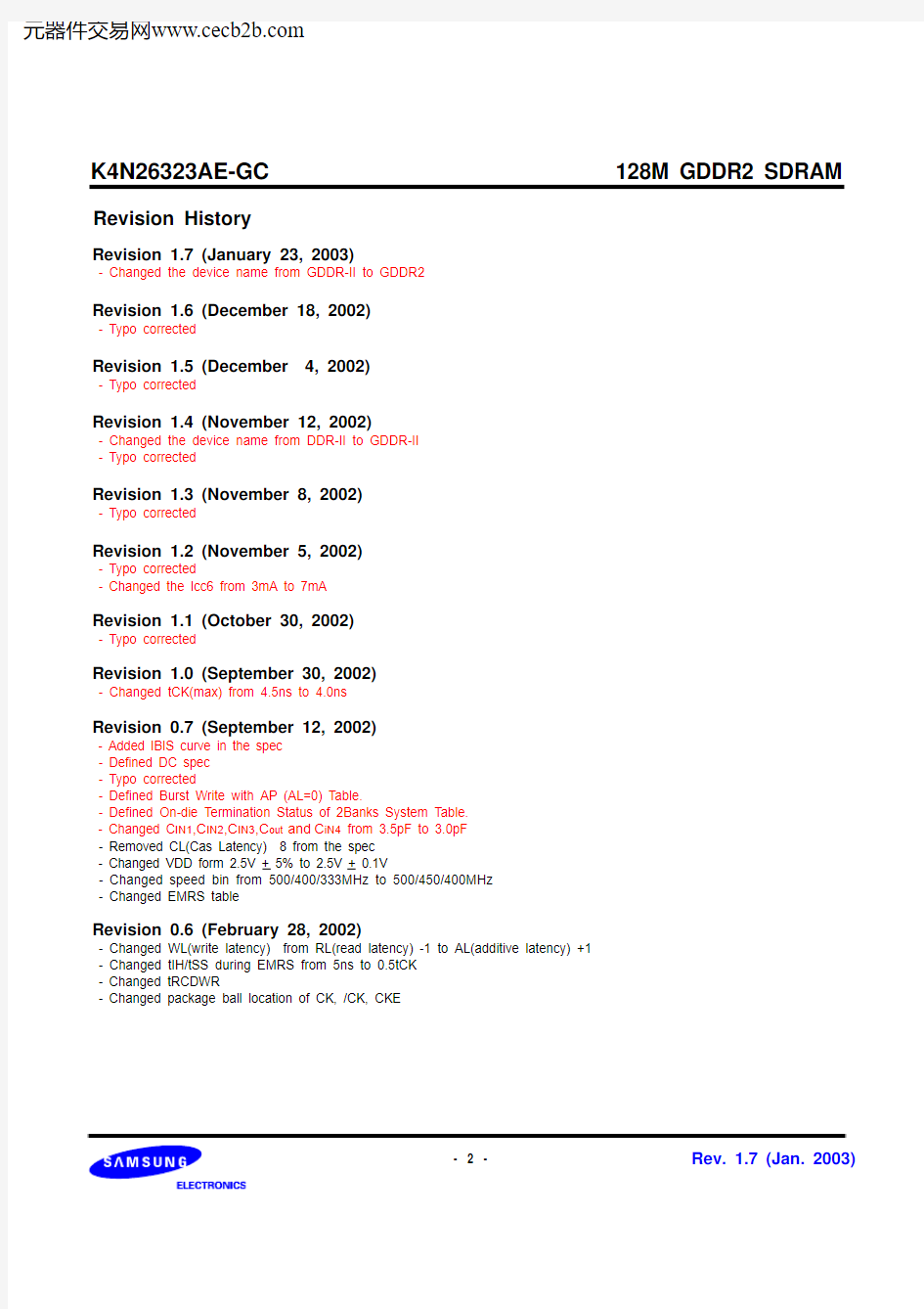
Revision History
Revision 1.7 (January 23, 2003)
- Changed the device name from GDDR-II to GDDR2
Revision 1.6 (December 18, 2002)
- Typo corrected
Revision 1.5 (December 4, 2002)
- Typo corrected
Revision 1.4 (November 12, 2002)
- Changed the device name from DDR-II to GDDR-II
- Typo corrected
Revision 1.3 (November 8, 2002)
- Typo corrected
Revision 1.2 (November 5, 2002)
- Typo corrected
- Changed the Icc6 from 3mA to 7mA
Revision 1.1 (October 30, 2002)
- Typo corrected
Revision 1.0 (September 30, 2002)
- Changed tCK(max) from 4.5ns to 4.0ns
Revision 0.7 (September 12, 2002)
- Added IBIS curve in the spec
- Defined DC spec
- Typo corrected
- Defined Burst Write with AP (AL=0) Table.
- Defined On-die Termination Status of 2Banks System Table.
- Changed C IN1,C IN2,C IN3,C out and C iN4 from 3.5pF to 3.0pF
- Removed CL(Cas Latency) 8 from the spec
- Changed VDD form 2.5V + 5% to 2.5V + 0.1V
- Changed speed bin from 500/400/333MHz to 500/450/400MHz
- Changed EMRS table
Revision 0.6 (February 28, 2002)
- Changed WL(write latency) from RL(read latency) -1 to AL(additive latency) +1
- Changed tIH/tSS during EMRS from 5ns to 0.5tCK
- Changed tRCDWR
- Changed package ball location of CK, /CK, CKE
- 2 -Rev. 1.7 (Jan. 2003)
128M GDDR2 SDRAM K4N26323AE-GC
Revision 0.5 (January 2002)
- Eliminated DLLEN pin
- Power-up sequence
Revision 0.4 (January 2002)
- Changed EMRS Table
- Changed Self-Refresh exit mode
- Changed On-die Termination Control
- Changed OCD Control method
- Power-up sequence
Revision 0.3 (December 2001)
- Noted the ball names changed from DDR-1 and exchanged DQS and /DQS ball location.
- Added On-die termination control
- Changed OCD align mode entry / exit timing
- Added target value of Data & DQS input/output capacitance(DQ0~DQ31)
- Added Table for auto precharge control
- Typo corrected.
Revision 0.2 (November 2001)
- Data Strobe Scheme is changed from DQS separation of Read DQS, Write DQS to Differential and Bi-directional DQS - OCD adjustment
- Controlled DQ is changed from DQ0, WDQS2 to DQ23, DQS2 and /DQS2
Revision 0.1 (October 2001)
- Data Strobe Scheme is changed from Bi-directional DQS to DQS separation to Read DQS, Write DQS
- Package Ball layout is changed for mirror package.
- OCD adjustment
Controlled DQ is changed from DQ0, DQS0 to DQ23, WDQS2
- Added DM descriptions
- 1bank, 2bank system
- Added System Selection mode in EMRS table.
Revision 0.0 (August 2001)
- 3 -Rev. 1.7 (Jan. 2003)
- 4 -
Rev. 1.7 (Jan. 2003)
128M GDDR2 SDRAM
K4N26323AE-GC
? 2.5V + 0.1V power supply for device operation ? 1.8V + 0.1V power supply for I/O interface ? On-Die Termination for all inputs except CKE,ZQ ? Output Driver Strength adjustment by EMRS ? SSTL_18 compatible inputs/outputs ? 4 banks operation
? MRS cycle with address key programs - CAS latency : 5, 6, 7 (clock) - Burst length : 4 only - Burst type : sequential only ? Additive latency (AL): 0,1(clock)? Read latency(RL) : CL+AL ? Write latency(WL) : AL+1
GENERAL DESCRIPTION
FEATURES
? Differential Data Strobes for Data-in, Date out ; - 4 DQS and /DQS(one differential strobe per byte) - Single Data Strobes by EMRS.? Edge aligned data & data strobe output ? Center aligned data & data strobe input ? DM for write masking only ? Auto & Self refresh
? 32ms refresh period (4K cycle)
(16ms is under consideration)
? 144 Ball FBGA
? Maximum clock frequency up to 500MHz ? Maximum data rate up to 1Gbps/pin ? DLL for Address, CMD and outputs
1M x 32Bit x 4 Banks GDDR2 Synchronous DRAM with Differential Data Strobe ORDERING INFORMATION
Part NO.Max Freq.Max Data Rate Interface
Package
K4N26323AE-GC20500MHz 1000Mbps/pin SSTL_18
144 Ball FBGA
K4N26323AE-GC22450MHz 900Mbps/pin K4N26323AE-GC25
400MHz
800Mbps/pin
The 4Mx32 GDDR2 is 134,217,728 bits of hyper synchronous data rate Dynamic RAM organized as 4 x 1,048,976 words by 32 bits, fabricated with SAMSUNG ’s high performance CMOS technology. Synchronous features with Data Strobe allow extremely high performance up to 4GB/s/chip. I/O transactions are possible on both edges of the clock cycle. Range of operating frequencies, and programmable latencies allow the device to be useful for a variety of high performance memory system applications.
FOR 1M x 32Bit x 4 Bank GDDR2 SDRAM
- 5 -
Rev. 1.7 (Jan. 2003)
128M GDDR2 SDRAM
K4N26323AE-GC
PIN CONFIGURATION
NOTE :
1. RFU1 is reserved for A12
2. RFU2 is reserved for BA2
3. (M,13) VREF for CMD and ADDRESS
4. (M,2) VREF for Data input
DQ23A3VDD VSS RFU 2VDD VDD RFU 1VSS VDD A4DQ8VREF A2A10/RAS NC CKE NC ZQ /CS A9A5VREF A0
A1
A11
BA0
/CAS
CK
/CK
/WE
BA1
A8/AP
A6
A7
2345678910111213B C D E F G H J K L M N
DQS0/DQS0VSSQ DQ3DQ2DQ0DQ31DQ29DQ28VSSQ /DQS3DQS3DQ4DM0VDDQ VDDQ DQ1VDDQ VDDQ DQ30VDDQ VDDQ DM3DQ27DQ6DQ5VSSQ VSSQ VSSQ VDD VDD VSSQ VSSQ VSSQ DQ26DQ25DQ7VDDQ VDD VSS VSSQ VSS VSS VSSQ VSS VDD VDDQ DQ24DQ17DQ16VDDQ VSSQ VSSQ VDDQ DQ15DQ14NC,VSS NC,VSS NC,VSS NC,VSS DQ19DQ18VDDQ VSSQ VSSQ VDDQ DQ13DQ12NC,VSS NC,VSS NC,VSS NC,VSS DQS2/DQS2NC VSSQ VSSQ NC /DQS1DQS1NC,VSS NC,VSS NC,VSS NC,VSS DQ20DM2VDDQ VSSQ VSSQ VDDQ DM1DQ11NC,VSS NC,VSS NC,VSS NC,VSS DQ21DQ22VDDQ VSSQ VSS VSS VSS VSS VSSQ VDDQ DQ9DQ10Normal Package (Top View)
- 6 -
Rev. 1.7 (Jan. 2003)
128M GDDR2 SDRAM
K4N26323AE-GC
PIN CONFIGURATION
Mirror Package (Top View)
DQ23A3VDD VSS RFU 2VDD VDD RFU 1VSS VDD A4DQ8VREF A2A10/RAS NC CKE NC ZQ /CS A9A5VREF A0
A1
A11
BA0
/CAS
CK
/CK
/WE
BA1
A8/AP
A6
A7
2345678910111213B C D E F G H J K L M N
DQS0/DQS0VSSQ DQ3DQ2DQ0DQ31DQ29DQ28VSSQ /DQS3DQS3DQ4DM0VDDQ VDDQ DQ1VDDQ VDDQ DQ30VDDQ VDDQ DM3DQ27DQ6DQ5VSSQ VSSQ VSSQ VDD VDD VSSQ VSSQ VSSQ DQ26DQ25DQ7VDDQ VDD VSS VSSQ VSS VSS VSSQ VSS VDD VDDQ DQ24DQ17DQ16VDDQ VSSQ VSSQ VDDQ DQ15DQ14NC,VSS NC,VSS NC,VSS NC,VSS DQ19DQ18VDDQ VSSQ VSSQ VDDQ DQ13DQ12NC,VSS NC,VSS NC,VSS NC,VSS DQS2/DQS2NC VSSQ VSSQ NC /DQS1DQS1NC,VSS NC,VSS NC,VSS NC,VSS DQ20DM2VDDQ VSSQ VSSQ VDDQ DM1DQ11NC,VSS NC,VSS NC,VSS NC,VSS DQ21DQ22VDDQ VSSQ VSS VSS VSS VSS VSSQ VDDQ DQ9DQ10* Under consideration
128M GDDR2 SDRAM K4N26323AE-GC
INPUT/OUTPUT FUNCTIONAL DESCRIPTION
Symbol Type Function
CK, CK Input Clock:CK and CK are differential clock inputs. CMD, ADD inputs are sampled on the crossing of the positive edge of CK and negative edge of CK. Output (read) data is referenced to the crossings of CK and CK (both direc-tions of crossing).
CKE Input Clock Enable: CKE HIGH activates, and CKE Low deactivates, internal clock signals and device input buffers and output drivers. Taking CKE Low provides Precharge Power-Down and Self Refresh operation (all banks idle), or Active Power-Down (row Active in any bank). CKE is synchronous for power down entry and exit, and for self refresh entry. CKE is asynchronous for self refresh exit. CKE must be maintained high throughout read and write accesses. Input buffers, excluding CK, CK and CKE are disabled during power-down. Input buffers, excluding CKE, are disabled during self refresh.
CS Input Chip Select: All commands are masked when CS is registered HIGH. CS provides for external bank selection on systems with multiple banks. CS is considered part of the command code.
RAS,
CAS,
WE
Input Command Inputs: RAS, CAS and WE (along with CS) define the command being entered.
DM0
~DM3Input Input Data Mask: DM is an input mask signal for write data. Input data is masked when DM is sampled HIGH coincident with that input data during a Write access. DM is sampled on both edges of clock. Although DM pins are input only, the DM loading matches the DQ and DQS loading.
BA0,
BA1Input Bank Address Inputs: BA0 and BA1 define to which bank an Active, Read, Write or Precharge command is being applied. BA0 also determines if the mode register or extended mode register is to be accessed during a MRS or EMRS cycle.
A0 -
A11Input Address Inputs: Provided the row address for Active commands and the column address and Auto Precharge bit for Read/Write commands to select one location out of the memory array in the respective bank. A8 is sampled during a Precharge command to determine whether the Precharge applies to one bank (A8 LOW) or all banks (A8 HIGH). If only one bank is to be precharged, the bank is selected by BA0, BA1. The address inputs also provide the op-code during Mode Register Set commands.
DQ Input/
Output Data Input/ Output: Bi-directional data bus. DQS0~
DQS3 DQS0~ DQS3Input/
Output
Data Strobe: output with read data, input with write data for source synchronous operation.Edge-aligned with read data, centered in write data.
DQS Scheme Differential DQS per byte
DQS0, DQS0DQS0 for DQ0-DQ7
DQS1, DQS1DQS1 for DQ8-DQ15
DQS2, DQS2DQS2 for DQ16-DQ23
DQS3, DQS3DQS3 for DQ24-DQ31
NC/
RFU No Connect: No internal electrical connection is present.
V DDQ Supply DQ Power Supply: 1.8V ± 0.1V
V SSQ Supply DQ Ground
V DD Supply Power Supply: 2.5V ± 0.1V
V SS Supply Ground
V REF Supply Reference voltage: half Vddq ,
2 Pins : (M,2) for Data input , (M,13) for CMD and ADDRESS
ZQ input Resistor connection pin for On-die termination.
The value of Resistor = 2 X (target value (Rterm) of termination resistance of DQ pin of each chip)
- 7 -Rev. 1.7 (Jan. 2003)
128M GDDR2 SDRAM K4N26323AE-GC
- 8 -Rev. 1.7 (Jan. 2003)
- 9 -
Rev. 1.7 (Jan. 2003)
128M GDDR2 SDRAM
K4N26323AE-GC
Self Auto Idle
MRS EMRS
Row Precharge Power Write Power ACT
Read A
Read
REFS
REFSX
REFA
CKEL
MRS
CKEH
CKEH
CKEL
Write
Power Applied
Automatic Sequence Command Sequence
Read A Write A
Read
PRE
PRE
PRE
PRE
Refresh
Refresh
Down
Power Down
Active
On
A
Read A Read A
Write A
PREALL
Active Precharge Precharge PREALL
Read
Write
PREALL = Precharge All Banks MRS = Mode Register Set
EMRS = Extended Mode Register Set REFS = Enter Self Refresh REFSX = Exit Self Refresh REFA = Auto Refresh CKEL = Enter Power Down CKEH = Exit Power Down ACT = Active
Write A = Write with Autoprecharge Read A = Read with Autoprecharge PRE = Precharge
FUNTIONAL DESCRIPTION Simplified State Diagram
DLL Enable
Write
- 10 -
Rev. 1.7 (Jan. 2003)
128M GDDR2 SDRAM
K4N26323AE-GC
Power-Up Sequence
GDDR2 SDRAMs must be powered up and initialized in a predefined manner to prevent undefined operations. 1. Power Up Sequence
- Apply Power and Keep CKE at low state. (All other inputs may be undefined) - Apply VDD before VDDQ. - Apply VDDQ before VREF.
- Start low frequency clock (100MHz) and maintain stable condition for minimum 200us.
- The minimum of 200us after stable power and clock (CK, /CK), apply NOP and take CKE to be high. - Issue precharge command for all banks of the device ( tS/tH =0.5tCK).
- Issue EMRS command to initialize DRAM with DLL OFF and On-die Termination OFF( tS/tH=0.5tCK) .
- Issue EMRS command to control DLL and decide on-die termination state.
Within 100 clocks after issuing EMRS command for DLL on, stable high frequency clock should be supplied to DRAM.
(V=Valid value)
- The additional 1ms clock cycles are required to lock the DLL and determine value of on-die termination after issuing EMRS command or supplying stable clock from a controller. Apply NOP during Locking DLL to protect invalid command. - Issue precharge command for all banks of the device. - Issue EMRS command
- Issue at least 10 or more Auto refresh command to update the value of on-die termination. - Issue a MRS command to initialize the mode register. - Issue any command.
Power up & Initialization Sequence
CMD
tRP
CK,CK
~
CKE
Precharge
NOP
1st Auto
Refresh 10th Auto Refresh
tRFC MRS
4 Clock min.
Any
Command
1ms
200 us
EMRS 2< 100tCK
all banks
stable high freq.
NOP
* Minimum setup/hold time tIS, tIHmin = 0.5tCK at the Low frequency without DLL * Within 100 tCK after issuing EMRS2, PLL(DLL) of controller should be enabled.
* During changing clock frequency, the changing rate should be smaller than 100ps/30tCK
low freq. (> 100Mhz)
EMRS 1NOP NOP EMRS Precharge all banks tRP tMRD Address Bus
BA 1BA 0A 11A 10A 9A 8A 7A 6A 5A 4A 3A 2A 1A 00
1
0X
X
X
X
Extended Mode Register
Address Bus
BA 1BA 0A 11A 10A 9A 8A 7A 6A 5A 4A 3A 2A 1A 00
1
V
V
1
V
V
V
V
Extended Mode Register
tRFC
128M GDDR2 SDRAM K4N26323AE-GC
The mode register stores the data for controlling the various operating modes of GDDR2 SDRAM. It programs CAS latency, addressing mode, test mode and various vendor specific options to make GDDR2 SDRAM useful for variety of dif-ferent applications. The default value of the mode register is not defined, therefore the mode register must be written after EMRS setting for proper operation. The mode register is written by asserting low on CS, RAS, CAS and WE (The GDDR2 SDRAM should be in active mode with CKE already high prior to writing into the mode register). The state of address pins A0 ~ A11 and BA0, BA1 in the same cycle as CS, RAS, CAS and WE going low is written in the mode register. Minimum four clock cycles are requested to complete the write operation in the mode register. The mode register contents can be changed using the same command and clock cycle requirements during operation as long as all banks are in the idle state. The mode register is divided into various fields depending on functionality. The burst length uses A0 ~ A2, addressing mode uses A3, CAS latency (read latency from column address) uses A4 ~ A6. A7 is used for test mode. A9 ~ A11 are used for tWR. Refer to the table for specific codes for various addressing modes and CAS latencies.
MODE REGISTER SET(MRS)
Address Bus
Mode Register
CAS Latency
A6A5A4Latency
000Reserved
001Reserved
010Reserved
011Reserved
100Reserved
1015
1106
1117
tWR
A11A10A9MRS Select
000Reserved
001Reserved
0103
0114
1005
101Reserved
110Reserved
111Reserved
*1. BL 4, Sequential Only
BA1BA0A11A10A9A8A7A6A5A4A3A2A1A0
00tWR0TM CAS Latency BT Burst Length
Test Mode
A7mode
0Normal
1Test
Burst Length
A2A1A0Burst Length
0104
Burst Type
A3Burst Type
0Sequential
BA0A n ~ A0
0MRS
1EMRS
*
*1
- 11 -Rev. 1.7 (Jan. 2003)
- 12 -
Rev. 1.7 (Jan. 2003)
128M GDDR2 SDRAM
K4N26323AE-GC
Output Driver Strength Option A 9A 8A 7Ron[ohm]000600015501050011451004010135110301
1
1
25
The extended mode register stores the data output driver strength and on-die termination options. The extended mode register is written by asserting low on CS, RAS, CAS, WE and high on BA0(The GDDR2SDRAM should be in all bank precharge with CKE already high prior to writing into the extended mode regis-ter). The state of address pins A0 ~ A11 and BA0 in the same cycle as CS, RAS, CAS and WE going low are written in the extended mode register. Four clock cycles are required to complete the write operation in the extended mode register. 8 kinds of the output driver strength are supported by EMRS (A9, A8, A7) code. The mode register contents can be changed using the same command and clock cycle requirements during opera-tion as long as all banks are in the idle state. "High" on BA0 is used for EMRS. Refer to the table for specific codes.
DLL A 6 DLL 0DLLOFF 1
DLLON
EXTENDED MODE REGISTER SET(EMRS)
Address Bus Extended
BA 1
BA 0
A 11
A 10
A 9A 8A 7A 6
A 5
A 4
A 3A 2A 1A 00
1
ODT.R
Output driver strength DLL
DQS
A.L
ODT control
ODT option Mode Register
OFF : On-die Termination of CMD and ADDR pins on DRAM is off X1 : On-die Termination value of CMD and ADD pins are same as the value of DQ
X2 : 2 times of the value of DQ X4 : 4 times of the value of DQ
On-die Termination option
for CMD & ADDR A 1A 0Value 00OFF 01X110X21
1
X4
ODT of DQs @ RD A 10mode 0ON 1
OFF
BA 0A n ~ A 00MRS 1
EMRS
On-Die Termination Mode
A 3A 2 Value 00 ODT OFF 01 ODT Cal. ON 10 Rterm=601
1
Rterm=120
*1. DLL control,ODT control,and ODT option command should be issued at low frequency clock(<100Mhz) with tIS/tIH=0.5tCK
*1
*1
Additive Latency A 4Latency
001
1
*2
*2. When single DQS is selected, 4 /DQS pins should be connected to VREF.
*1DQS
A 5
DQS 0Differential 1
Single
128M GDDR2 SDRAM K4N26323AE-GC
- 13 -Rev. 1.7 (Jan. 2003)
128M GDDR2 SDRAM K4N26323AE-GC
- 14 -Rev. 1.7 (Jan. 2003)
128M GDDR2 SDRAM K4N26323AE-GC
- 15 -Rev. 1.7 (Jan. 2003)
128M GDDR2 SDRAM K4N26323AE-GC
- 16 -Rev. 1.7 (Jan. 2003)
128M GDDR2 SDRAM K4N26323AE-GC
- 17 -Rev. 1.7 (Jan. 2003)
128M GDDR2 SDRAM K4N26323AE-GC
- 18 -Rev. 1.7 (Jan. 2003)
128M GDDR2 SDRAM K4N26323AE-GC
- 19 -Rev. 1.7 (Jan. 2003)
128M GDDR2 SDRAM K4N26323AE-GC
- 20 -Rev. 1.7 (Jan. 2003)