Dynamic Replier Active Reliable Multicast (DyRAM)
- 格式:pdf
- 大小:226.62 KB
- 文档页数:8
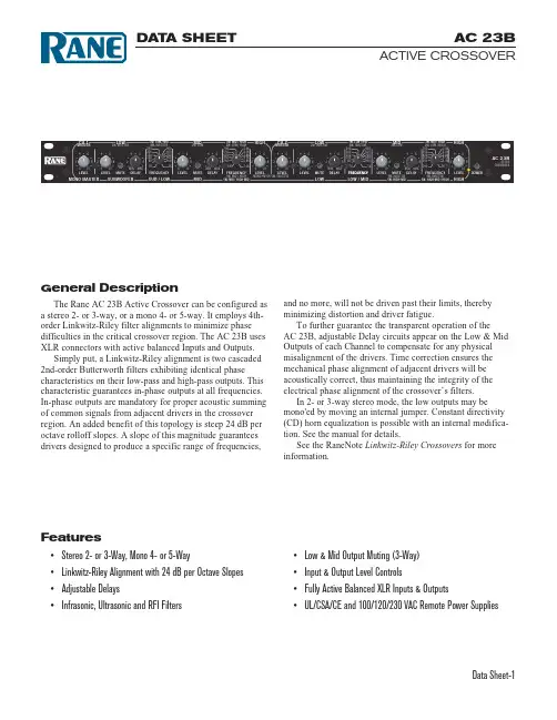
AC 23BACTIVE CROSSOVERData Sheet-1Features• Stereo 2- or 3-Way, Mono 4- or 5-Way• Linkwitz-Riley Alignment with 24 dB per Octave Slopes • Adjustable Delays• Infrasonic, Ultrasonic and RFI FiltersGeneral DescriptionThe Rane AC 23B Active Crossover can be configured asa stereo 2- or 3-way, or a mono 4- or 5-way. It employs 4th-order Linkwitz-Riley filter alignments to minimize phase difficulties in the critical crossover region. The AC 23B uses XLR connectors with active balanced Inputs and Outputs.Simply put, a Linkwitz-Riley alignment is two cascaded 2nd-order Butterworth filters exhibiting identical phasecharacteristics on their low-pass and high-pass outputs. This characteristic guarantees in-phase outputs at all frequencies.In-phase outputs are mandatory for proper acoustic summing of common signals from adjacent drivers in the crossover region. An added benefit of this topology is steep 24 dB per octave rolloff slopes. A slope of this magnitude guarantees drivers designed to produce a specific range of frequencies,and no more, will not be driven past their limits, thereby minimizing distortion and driver fatigue.To further guarantee the transparent operation of the AC 23B, adjustable Delay circuits appear on the Low & Mid Outputs of each Channel to compensate for any physical misalignment of the drivers. Time correction ensures the mechanical phase alignment of adjacent drivers will be acoustically correct, thus maintaining the integrity of the electrical phase alignment of the crossover’s filters.In 2- or 3-way stereo mode, the low outputs may be mono'ed by moving an internal jumper. Constant directivity (CD) horn equalization is possible with an internal modifica-tion. See the manual for details.See the RaneNote Linkwitz-Riley Crossovers for more information.DA T A SHEET • Low & Mid Output Muting (3-Way)• Input & Output Level Controls• Fully Active Balanced XLR Inputs & Outputs• UL/CSA/CE and 100/120/230 VAC Remote Power SuppliesAC 23BACTIVE CROSSOVERData Sheet-2re t e m a r a P n o i t a c if i c e p S ti m i L st i n U st n e m m o C /s n o i t i d n o C t n e m n g i l A :r e v o s s o r C y e l i R -z t i w k n i L e l b a i r a v -e t a t s r e d r o -h t 4y r a t e i r p o r P se p o l S ..........ev a t c O /B d 42)y a w -3(e g n a R ..........d i M o t w o L z H k 1-07t o p e l b a i r a v y l s u o u n i t n o c t n e t e d -14)y a w -3(e g n a R ..........h g i H o t d i M z H k 7-091e v o b a s a )y a w -2(e g n a R ..........h g i H o t w o L z H k 7-091ev o b a s a e g n a R t s u j d A y a l e D e m i T 2+o t f f O %5sm y l n o s t u p t u O d i M &w o L e p y T :s t u p n I d e c n a l a B e v i t c A sr o t c e n n o C ..........R L X sd r a d n a t s S E A r e p t o h 2n i P l e v e L m u m i x a M (1)2+1u B d e g n a R n i a G ..........6+o t f f O 4+/0-B d e c n a d e p m I ..........k021Ωe p y T :s t u p t u O d e c n a l a B e v i t c A s r o t c e n n o C ..........R L X sd r a d n a t s S E A re p t o h 2n i P ec n a d e p m I ..........002%1Ωl e v e L m u m i x a M . 02+1u B d 006Ωr e t a e r g r o eg n a R n i a G ..........21+o t f f O 4+/0-Bd se h c t i w S g n i t u M d n a B s e Y yl n o s t u p t u O d i M &w o L sr e t l i F I F R se Y r e t l i F c i n o s a rf n I h t r o w r e t t u B ,.t c o /B d 81,z H 02%3z H r e t l i F c i n o s a r t l U l e s s e B ,.t c o /B d 81,z H k 04%3z H es a h p r a e n i L e s n o p s e R y c n e u q e r F z H k 04-023-/0+B d es i o N +D H T 20.010.%zH k 02-02,u B d 4+)E T P M S (n o i t r o t s i D M I 20.010.%uB d 4+,1:4,z H k 7/z H 06o i t a R e s i o N -o t -l a n g i S 292Bd h t d i w d n a be s i o n z H k 02,u B d 4+e r g n i t s i L y c n e g A :t i n U l e d o m C A V 021..........t n e m p i u q E 2s s a l C e d o C l a c i r t c e l E l a n o i t a N A S C &L U 2s s a l C le d o m C A V 032..........V L E S ,E D V e g a t l o V w o L a r t x E y t ef a S C M E -E C CE E /633/98e v i t c e r i d C M E yt e f a S -E C C E E /32/37D V L ,1.t r A r e p t p m e x E g n i t s i L y c n e g A :y l p p u S r e w o P l e d o m C A V 021..........L U 16288E .o n e l i F A S C 84985R L .o n e l i F l e d o m C A V 032..........C M E -E C C E E /633/98e v i t c e r i d C M E y t e f a S -E C C E E /32/37e v i t c e r i d V L l e d o m C A V 001..........SI J o t t l i u B y l n o n a p a J t n e m r i u q e R y l p p u S r e w o P p a t r e t n e c /w C A V 811.0s m r V 1S R l e d o M t n e r r u C m u m i x a M 057Am y l p p u S e t o m e R m o r f t n e r r u C S M R n o i t c u r t s n o C :t i n U le e t S l l A e z i S ..........)U 1(D "3.5x W "91x H "57.1)m c 3.31x m c 3.84x m c 4.4(t h g i e W ..........bl 5)g k 3.2(e z i S :g n i p p i h S "57.31x "3.02x "52.4)m c 53x m c 25x m c 5.11(th g i e W ..........bl 9)g k 1.4(sm r V 577.0=u B d 0:e t o N Features and SpecificationsAC 23BACTIVE CROSSOVERData Sheet-3Block DiagramAC 23BACTIVE CROSSOVERData Sheet-4All features & specifications subject to change without notice. DOC 107496©Rane Corporation 10802 47th Ave. W., Mukilteo WA 98275-5098 USA T EL 425-355-6000 FAX 425-347-7757 WEB References1. S.H. Linkwitz, “Active Crossover Networks for Noncoincident Drivers,” J. Audio Eng. Soc ., vol. 24, pp. 2-8 (Jan/Feb 1976).2. D. Bohn, “A Fourth-Order State-Variable Filter for Linkwitz-Riley Active Crossover Designs,” presented at the 74th Convention of the Audio Engineering Society, New York, Oct. 9-12, 1983, preprint no. 2011.3. D. Bohn, “Linkwitz-Riley Crossovers,” RaneNote , (1983).4. D. Bohn, “Why Not Wye?” RaneNote , (1984).5. D. Bohn, “Linkwitz-Riley Active Crossovers Up To 8th-Order: An Overview,” RaneNote, (1989).Rear PanelAvailable Accessories • SC 1.7 Security Cover Architectural SpecificationsThe active crossover shall contain 4th-order Linkwitz-Riley filters. Provisions shall exist to correct for driver misalignment by adding time delay to the low and mid frequency outputs.The crossover frequency shall be controlled by a continu-ously variable control with 41 detents to allow mechanical reference of crossover setting.Signal inputs and outputs shall be of active balanceddesign terminated with XLR connectors. RFI, infrasonic, and ultrasonic filters shall be built-in.The active crossover shall afford an input level range of Off to +6 dB. The output level controls shall afford a level range of from Off to +12 dB with muting capability on the low and mid frequency outputs. The crossover shall supply two independent channels.The unit shall be exempt from agency safety requirements and powered from a UL listed, CSA certified remote power supply (120 VAC) or CE approved (230 VAC) via a rear panel modular plug input. The unit shall be constructedentirely from cold-rolled steel, and mount into a standard 1U EIA rack.The unit shall be a Rane Corporation AC 23B Active Crossover.Choosing the Right Configuration:Mono, Dual Mono, or Stereo?Very few systems indeed will utilize a two channel crossover for the purpose of true stereo imaging. Discrete stereo channels which are run from the mixing board are usually used for panning effects and/or for separate equaliza-tion of left and right speaker stacks. Different sides of the room often require significantly different equalization due to varying room acoustics, dimensions, positioning of speaker stacks near walls, curtains and the like.Even though you may not plan to use stereo equalization or panning effects, it is recommended that your system utilize discrete crossover channels for each stack of speakers to ensure flexibility and control for consistent, optimum sound quality. For example, if you plan to run a multi-stack system mono three-way, use the AC 23B rather than the AC 22B for separate control over each set of speakers—especially since phase alignment may differ with each stack requiring separate time delay adjustments. Even with only a single system equalizer, the AC 23B can deliver the extra independent control which can make a difference in sound throughout the listening area. If all drivers are built into a single cabinet, or you are running bi-amped monitors, then the AC 22B is the one for you.。
Protecting business-critical data stored in Oracle databases while keepingthat data online and available is easier when you have a solution with a plug-in specifically designed for Oracle. With Quest® NetVault Backup, you’ll be able to take full advantage of the world’s leading relational database management system. NetVault Backup gives you confidence that you can recover your Oracle environments, including Oracle Real Application Clusters (RAC) and Data Guard, while eliminating the need for complex scripting. Through an intuitive user interface and automated workflow processes, NetVault Backup offers a centralized console to help you set up, configure and define backup and restore policies for all your Oracle databases. Plus, you have the flexibility to select your preferred backup method without having to learn Oracle database internals, thanks to support for online backups via simple user-managed or full-featured Recovery Manager (RMAN) backups. NetVault Backup also offers granular control that minimizes downtime, providing youwith faster and more reliable backups and restores of complete databases, individual tablespaces or individual datafiles. Through automatic integration with a wide range of backup devices, you can be confident that your Oracle data is protected and safely stored off site to meet your disaster recovery and business continuity goals.NetVault Backup supports important features such as Oracle RAC, Data Guard, Automated Storage Management (ASM), Flashback Database and Transparent Data Encryption, and offers you advanced backup and recovery options in case of hardware failure or data loss. Protect your business-critical Oracle data with confidence and agility.NetVault Backup for OracleAward-winning protection for business-critical data stored in Oracle databasesBENEFITS:• User-managed or RMAN-basedonline backups• Support for RMAN compression• Protection for single-instance,multi-instance RAC and DataGuard environments• Protection for Oracle datain third-party (non-RAC)clustered environments• Backup Parameter, Control,Archived Redo Log Files andExternal Configuration Files• Protection down to datafile levels• Automatic instance configuration• Point-and-click graphic userinterface (GUI)KEY BENEFITSReduce risk with flexible backup and recovery — NetVault Backup gives you tools to simplify backup and recovery of business-critical Oracle databases. With NetVault Backup, you can create a comprehensive and flexible backup policy without the need to understand Oracle database internals. You have the flexibility to choose between simple user-managed or full-featured RMAN-based backups. Through point-and-click automated options, NetVault Backup reduces reliance on human interaction, which eliminates syntax errors caused by manual intervention.Minimize downtime by speeding uprestores (restore only what is needed) — NetVault Backup ensures databases remain online and fully accessible during backup operations, ensuring no user downtime. Integration withOracle’s Flashback Database maximizes availability by enabling you to rewind to a previous time to correct problems caused by logical data corruptions or user errors without restoring physical datafiles. When needed, you can perform full, incremental, and time-, SCN- and log sequence number-based, point-in-time restores. NetVault Backup is designedfor granular recoveries, enabling you to recover complete databases, individual tablespaces or individual datafiles.Increase business continuity through automatic integration with a widerange of backup devices — With off-site backups being an important part of the data protection plan for business-critical applications, NetVault Backup integrates with a wide range of storage devices, enabling you to store backup data on disk, in a virtual tape library (VTL) or on tape.ABOUT QUESTQuest helps our customers reducetedious administration tasks so they can focus on the innovation necessary for their businesses to grow. Quest® solutions are scalable, affordable and simple-to-use, and they deliver unmatched efficiency and productivity. Combined with Quest’s invitation to the global community to be a part of its innovation, as well as our firm commitment to ensuring customer satisfaction, Quest will continue to accelerate the delivery of the mostcomprehensive solutions for Azure cloud management, SaaS, security, workforcemobility and data-driven insight.Quest, NetVault and the Quest logo are trademarks and registered trademarks of Quest Software Inc. For a complete list of Quest marks, visit /legal/trademark-information.aspx. All other trademarks and registered trademarks are property of their respective owners.© 2017 Quest Software Inc. ALL RIGHTS RESERVED.DataSheet-NVBU4Oracle-US-KS-25712Quest4 Polaris Way, Aliso Viejo, CA 92656 | If you are located outside North America, you can find local office information on our Web site.。
OBJECTIVESOLIDWORKS® Flow Simulation is a powerful Computational Fluid Dynamics (CFD) solution fully embedded within SOLIDWORKS. It enables designers and engineers to quickly and easily simulate the effect of fluid flow, heat transfer and fluid forces that are critical to the success of their designs.OVERVIEWSOLIDWORKS Flow Simulation enables designers to simulate liquid and gas flow in real-world conditions, run “what if” scenarios and efficiently analyze the effects of fluid flow, heat transfer and related forces on or through components. Design variations can quickly be compared to make better decisions, resulting in products with superior performance. SOL IDWORKS Flow Simulation offers two flow modules that encompass industry specific tools, practices and simulation methodologies—a Heating, Ventilation and Air Conditioning (HVAC) module and an Electronic Cooling module. These modules are add-ons to a SOLIDWORKS Flow Simulation license. BENEFITS• Evaluates product performance while changing multiple variables at a rapid pace.• Reduces time-to-market by quickly determining optimal design solutions and reducing physical prototypes.• Enables better cost control through reduced rework and higher quality.• Delivers more accurate proposals.CAPABILITIESSOLIDWORKS Flow SimulationSOLIDWORKS Flow Simulation is a general-purpose fluid flow and heat transfer simulation tool integrated with SOLIDWORKS 3D CAD. Capable of simulating both low-speed and supersonic flows, this powerful 3D design simulation tool enables true concurrent engineering and brings the critical impact of fluid flow analysis and heat transfer into the hands of every designer. In addition to SOL IDWORKS Flow Simulation, designers can simulate the effects of fans and rotating components on the fluid flow and well as component heating and cooling. HVAC ModuleThis module offers dedicated simulation tools for HVAC designers and engineers who need to simulate advanced radiation phenomena. It enables engineers to tackle the tough challenges of designing efficient cooling systems, lighting systems or contaminant dispersion systems. Electronic Cooling ModuleThis module includes dedicated simulation tools for thermal management studies. It is ideal for companies facing thermal challenges with their products and companies that require very accurate thermal analysis of their PCB and enclosure designs.SOLIDWORKS Flow Simulation can be used to:• Dimension air conditioning and heating ducts with confidence, taking into account materials, isolation and thermal comfort.• Investigate and visualize airflow to optimize systems and air distribution.• Test products in an environment that is as realistic as possible.• Produce Predicted Mean Vote (PMV) and Predicted Percent Dissatisfied (PPD) HVAC results for supplying schools and government institutes.• Design better incubators by keeping specific comfort levels for the infant and simulating where support equipment should be placed.• Design better air conditioning installation kits for medical customers.• Simulate electronic cooling for LED lighting.• Validate and optimize designs using a multi-parametric Department of Energy (DOE) method.SOLIDWORKS FLOW SIMULATIONOur 3D EXPERIENCE® platform powers our brand applications, serving 12 industries, and provides a rich portfolio of industry solution experiences.Dassault Syst èmes, t he 3D EXPERIENCE® Company, provides business and people wit h virt ual universes t o imagine sust ainable innovat ions. It s world-leading solutions transform the way products are designed, produced, and supported. Dassault Systèmes’ collaborative solutions foster social innovation, expanding possibilities for the virtual world to improve the real world. The group brings value to over 220,000 customers of all sizes in all industries in more than 140 countries. For more information, visit .Europe/Middle East/Africa Dassault Systèmes10, rue Marcel Dassault CS 4050178946 Vélizy-Villacoublay Cedex France AmericasDassault Systèmes 175 Wyman StreetWaltham, Massachusetts 02451-1223USA Asia-PacificDassault Systèmes K.K.ThinkPark Tower2-1-1 Osaki, Shinagawa-ku,Tokyo 141-6020Japan©2018 D a s s a u l t S y s t èm e s . A l l r i g h t s r e s e r v e d . 3D E X P E R I E N C E ®, t h e C o m p a s s i c o n , t h e 3D S l o g o , C A T I A , S O L I D W O R K S , E N O V I A , D E L M I A , S I M U L I A , G E O V I A , E X A L E A D , 3D V I A , B I O V I A , N E T V I B E S , I F W E a n d 3D E X C I T E a r e c o m m e r c i a l t r a d e m a r k s o r r e g i s t e r e d t r a d e m a r k s o f D a s s a u l t S y s t èm e s , a F r e n c h “s o c i ét é e u r o p ée n n e ” (V e r s a i l l e s C o m m e r c i a l R e g i s t e r # B 322 306 440), o r i t s s u b s i d i a r i e s i n t h e U n i t e d S t a t e s a n d /o r o t h e r c o u n t r i e s . A l l o t h e r t r a d e m a r k s a r e o w n e d b y t h e i r r e s p e c t i v e o w n e r s . U s e o f a n y D a s s a u l t S y s t èm e s o r i t s s u b s i d i a r i e s t r a d e m a r k s i s s u b j e c t t o t h e i r e x p r e s s w r i t t e n a p p r o v a l .• Free, forced and mixed convection• Fluid flows with boundary layers, including wall roughness effects• Laminar and turbulent fluid flows • Laminar only flow• Multi-species fluids and multi-component solids• Fluid flows in models with moving/rotating surfaces and/or parts• Heat conduction in fluid, solid and porous media with/without conjugate heat transfer and/or contact heat resistance between solids• Heat conduction in solids only • Gravitational effectsAdvanced Capabilities• Noise Prediction (Steady State and Transient)• Free Surface• Radiation Heat Transfer Between Solids • Heat sources due to Peltier effect• Radiant flux on surfaces of semi-transparent bodies• Joule heating due to direct electric current in electrically conducting solids• Various types of thermal conductivity in solid medium • Cavitation in incompressible water flows• Equilibrium volume condensation of water from steam and its influence on fluid flow and heat transfer• Relative humidity in gases and mixtures of gases • Two-phase (fluid + particles) flows • Periodic boundary conditions.• Tracer Study• Comfort Parameters • Heat Pipes • Thermal Joints• Two-resistor Components • PCBs•Thermoelectric Coolers• Test the heat exchange on AC and DC power converters.• Simulate internal temperature control to reduce overheating issues.• Better position fans and optimize air flux inside a design.• Predict noise generated by your designed system.Some capabilities above need the HVAC or Electronic Cooling Module.SOLIDWORK Design Support• Fully embedded in SOLIDWORKS 3D CAD• Support SOLIDWORKS configurations and materials • Help Documentation • Knowledge base• Engineering database• eDrawings ® of SOLIDWORKS Simulation results General Fluid Flow Analysis• 2D flow • 3D flow • Symmetry• Sector Periodicity • Internal fluid flows • External fluid flowsAnalysis Types• Steady state and transient fluid flows • Liquids • Gases• Non-Newtonian liquids • Mixed flows• Compressible gas and incompressible fluid flows •Subsonic, transonic and supersonic gas flowsMesher• Global Mesh Automatic and Manual settings • Local mesh refinementGeneral Capabilities• Fluid flows and heat transfer in porous media • Flows of non-Newtonian liquids • Flows of compressible liquids •Real gases。

存储HCIP模考试题与答案一、单选题(共38题,每题1分,共38分)1.某应用的数据初始容量是 500GB.,备份频率是每周 1 次全备,6 次增备,全备和增备的数据保存周期均为 4 周,冗余比为 20%。
则 4 周的后端存储容量为:A、3320GB.B、3504GB.C、4380GB.D、5256GB.正确答案:D2.以下哪个不是 NAS 系统的体系结构中必须包含的组件?A、可访问的磁盘阵列B、文件系统C、访问文件系统的接口D、访问文件系统的业务接口正确答案:D3.华为主备容灾方案信息调研三要素不包括哪一项?A、项目背景B、客户需求与提炼C、项目实施计划D、现网环境确认正确答案:C4.以下哪个不是华为 WushanFS 文件系统的特点A、性能和容量可单独扩展B、全对称分布式架构,有元数据节点C、元数据均匀分散,消除了元数据节点性能瓶颈D、支持 40PB 单一文件系统正确答案:B5.站点 A 需要的存储容量为 2543GB.,站点 B 需要的存储容量为3000GB.,站点 B 的备份数据远程复制到站点 A保存。
考虑复制压缩的情况,压缩比为 3,计算站点 A 需要的后端存储容量是多大?A、3543GB.B、4644GB.C、3865GB.D、4549GB.正确答案:A6.关于华为 Oceanstor 9000 各种类型节点下硬盘的性能,由高到低的排序正确的是哪一项?A、P25 Node SSD 硬盘-〉P25 Node SAS 硬盘-〉P12 SATA 硬盘-〉P36 Node SATA 硬盘-〉C36 SATA 硬盘B、P25 Node SSD 硬盘-〉P25 Node SAS 硬盘-〉P12 SATA 硬盘-〉C36 SATA 硬盘C、P25 Node SSD 硬盘-〉P25 Node SAS 硬盘-〉P36 Node SATA 硬盘-〉P12 SATA 硬盘-〉C36 SATA 硬盘D、P25 Node SSD 硬盘-〉P25 Node SAS 硬盘-〉P36 Node SATA 硬盘-〉C36 SATA 硬盘-〉P12 SATA 硬盘正确答案:C7.关于华为 Oceanstor 9000 软件模块的描述不正确的事哪一项?A、OBS(Object-Based Store)为文件系统元数据和文件数据提供可靠性的对象存储功能B、CA(Chent Agent)负责 NFS/CIFS/FTP 等应用协议的语义解析,并发送给底层模块处理C、快照、分级存储、远程复制等多种增值特性功能是由 PVS 模块提供的D、MDS(MetaData Service)管理文件系统的元数据,系统的每一个节点存储可所以元数据正确答案:D8.下面属于华为存储 danger 类型的高危命令的时哪个命令?A、reboot systemB、import configuration_dataC、show alarmD、chang alarm clear sequence list=3424正确答案:A9.华为 Oceanstor 9000 系统提供的文件共享借口不包括以下哪个选项?A、ObjectB、NFSC、CIFSD、FTP正确答案:A10.以下哪个选项不属于 oceanstor toolkit 工具的功能?A、数据迁移功能B、升级功能C、部署功能D、维护功能正确答案:A11.某用户用 Systemreporter 分析其生产设备 Oceanstor 9000 时发现某分区的部分节点 CPU 利用率超过 80%,但平均CPU 利用率约为 50%,另外发现某个节点的读写带宽始终保持在性能规格的 80%以上,其他节点则均在 60%以下,该场景下,推荐使用如下哪种负载均衡策略?A、轮循方式B、按 CPU 利用率C、按节点吞吐量D、按节点综合负致正确答案:D12.下列选项中关于对象存储服务(兼容 OpenStack Swift 接口) 概念描述错误的是:A、Account 就是资源的所有者和管理者,使用Account 可以对Container 进行增、删、查、配置属性等操作,也可以对 Object 进行上传、下载、查询等操作。

Purpose-built for transportation and logistics applications, the Honeywell Dolphin™ 99GX mobile computer with an integrated handle provides user-friendly ergonomics, cutting-edge wireless technology, multi-functional data capture and extreme durability for frontline workers operating in a variety of locations ranging from loading docks to retail.The reliable and intuitive Dolphin 99GX mobile computer delivers an outstanding feature set that enables improved productivity for mobile workers. Integrated Shift-PLUS™ technology provides all-day battery life, minimizing the time and expense incurred when batteries need to be charged or replaced. The Dolphin 99GX mobile computer is IP64-rated and can withstand multiple 1.8 meter (6 feet) drops to concrete, ensuring years of trouble-free operation.The Dolphin 99GX mobile computer features the latest in wireless technology, including a software-definable radio that allows on-the-fly switching between GSM and CDMA networks, leading to improved network coverage and lower costs related to device provisioning and deployment. Additionally, built-in Wi-Fi provides workers with access to critical data using the new, lightning-fast 802.11n standard while still supporting legacy a/b/g protocols. Integrated motion, light and proximity sensors help conserve battery life and improve ease of use by automatically optimizing the device for the current environment. Similarly, multiple keypadDolphin 99GXMobile ComputerFE AT U R ES & B EN EFI TSIncorporates anIP64-rated design that withstands multiple 1.8 meter (6 feet) drops to concrete and 2,000 1 meter tumbles, resulting in a lower total cost of ownership for enterprises.Enhances productivity by providing full-shift battery life, eliminating the need for employees to carry spare batteries or chargers.Enables multi-functional data capture byproviding fast scanning of linear and 2Dbarcodes with excellent motion tolerance, as well as seamless image capture.Delivers full wireless coverage forapplications inside and outside of the four walls, allowing real-time access to critical data.Comprehensive,hassle-free protection on the deviceinvestment – for up to five years after purchase – extends the product life expectancy beyond the norm for consumer-grade devices.options are available to ensure that the device is configured to meet diverse data input needs. With additional features such as an ultra-bright 94-millimeter (3.7-inch) display that can be read even in direct sunlight, the Dolphin 99GX mobile computer offers superior usability.Designed with input from leading companies in the transportation and logistics sector, the Dolphin 99GX mobile computer provides a rugged solution that increases productivity by connecting enterprises, frontline workers and customers using real-time wireless communication.The Dolphin 99GX mobile computer increases productivity by connecting enterprises, frontline workers and customers.Honeywell Sensing and Productivity Solutions 9680 Old Bailes Road Fort Mill, SC 99GX-DS Rev F 02/16© 2016 Honeywell International Inc.Microsoft and Windows are registered trademarks or trademarks of Microsoft Corporation.The Bluetooth trademark is owned by Bluetooth SIG, Inc. U.S.A. and licensed to Honeywell International Inc.Dolphin 99GX Technical SpecificationsMECHANICAL/ENVIRONMENTALDimensions: 215 mm L x 69 mm W (keypad) x 39 mm (standard battery)/45mm (extended battery); 8.5 in L x 2.7 in W (keypad) x 1.5 in (standard battery)/1.8 in (extended battery)Weight: Standard battery: 621 g (21.9 oz); Extended battery: 700 g (24.7 oz)Operating Temperature: -4°F to 122°F (-20°C to 50°C)Storage Temperature: -13°F to 158°F (-25°C to 70°C)Humidity: 95% humidity, non-condensing Drop: Withstands multiple 1.8 m (6 ft) drops to concrete, all axis, and across operating temperature rangeTumble: Up to 2,000 (1 m) tumbles per IEC 60068-2-32 specificationEnvironmental Sealing: Independently certified to meet IP64 standards for moisture and particle resistanceESD: Air: ±15 KV; Contact: ±8 KVSYSTEM ARCHITECTUREProcessor: Texas Instruments ® OMAP3715 1.0 GHz processorOperating System: Microsoft ® Windows ®Embedded Handheld 6.5 Professional and Classic Memory: 1 GB discrete NAND flash x 512 MB RAMDisplay: Chemically strengthened 94 mm (3.7 in) transflective active matrix glass display, VGA (480 x 640), 333 nitsTouch Panel: Industrial touch panel with resistive touch and support for finger touch and stylus Keypad: Backlit 55-key alphanumeric, 43-key alpha shifted numeric, 34-key numeric shifted alpha (phone or calculator style)Audio: Speaker, microphoneI/O Ports: RS-232/USB 2.0/audio out/charging connector, integrated IrDA port with support for SIR modeStorage Expansion: User-accessible Micro SDHC memory card slot. Please check current price guide for available qualified card options Battery: Standard: Li-ion, 3.7V, 3060mAh; Extended: Li-ion, 3.7V, 5000mAhBattery Life: Standard/Extended: 9 hours/15.5 hours (scanning and sending data over WLAN every 9 seconds)Standard/Extended: 8 hours/14.75 hours(scanning and sending data over WWAN every 15 seconds)Imager/Scanner: N5600/5603 Standard Range (SR), Extended Range (ER) and High Density (HD) imagers with high-visibility laser or green LED aimer. All imagers have 25° angle and come equipped with Adaptus™ 6.0 Imaging Technology Decode Capabilities: Reads standard 1D and 2D symbologiesDevelopment Environment: Honeywell SDK for Windows EmbeddedWarranty: One-year factory warrantyService Plans: Optional three- and five-year Honeywell Service Repair programs offer worry-free mobile computingWIRELESS CONNECTIVITYWWAN: GSM (Voice and Data): 3.9G - HSPA+ (800/850/900/1700/2100 MHz), GSM/GPRS/EDGE (850/900/1800/1900 MHz)Software-definable radio: 3.9G - HSPA+/UMTS (800/850/1900/2100 MHz),GSM GPRS/EDGE (850/900/1800/1900 MHz), EVDO Rev A – 1xRTT/EVDO (800/1900 MHz) support for dual SIM cardWLAN: 802.11a/b/g/n, Wi-Fi certifiedWLAN Security: WPA, WPA2 (Personal and Enterprise), 802.1x, EAP-TLS, EAP-TTLS/MSCHAPv2, PEAPv0/EAP-MSCHAPv2,PEAPv1/EAP-GTC, WMM, CWG-RF Profile, CCX v.4, WAPIWPAN: Bluetooth ® V2.1, support for enhanced data rate 2.0 Mbps and 3.0 Mbps rates class IIFor a complete listing of all compliance approvals and certifications, please visit /compliance . For a complete listing of all supported barcode symbologies, please visit /symbologies .。

《基于多样性SAT求解器和新颖性搜索的软件产品线测试》篇一一、引言随着软件工程领域的快速发展,软件产品线测试已成为确保软件质量和性能的关键环节。
在软件产品线测试中,求解器技术和搜索策略的选用显得尤为重要。
本文将探讨基于多样性SAT求解器和新颖性搜索的软件产品线测试,分析其优势及实施过程,以期为软件工程领域提供新的思路和方法。
二、SAT求解器在软件产品线测试中的应用SAT(Satisfiability Problem)求解器是一种用于解决逻辑满足性问题的工具。
在软件产品线测试中,SAT求解器可用于验证软件系统的逻辑正确性。
通过构建满足特定需求的逻辑表达式,SAT求解器能够快速找出满足条件的解,从而提高测试效率。
多样性SAT求解器是针对传统SAT求解器的局限性而提出的一种新型求解器。
它能够在搜索过程中生成多种解,从而提供更全面的测试覆盖。
在软件产品线测试中,多样性SAT求解器可以生成多种测试用例,以确保软件在不同场景下的稳定性和性能。
三、新颖性搜索在软件产品线测试中的重要性新颖性搜索是指在海量数据中寻找具有创新性和独特性的信息。
在软件产品线测试中,新颖性搜索对于发现潜在问题和提高测试质量具有重要意义。
通过新颖性搜索,测试人员可以快速定位到尚未被测试的代码区域和潜在风险点,从而提高测试的针对性和有效性。
四、基于多样性SAT求解器和新颖性搜索的软件产品线测试实施1. 确定测试目标:明确软件产品线测试的目标和需求,为后续的SAT求解器和新颖性搜索提供指导。
2. 构建逻辑表达式:利用SAT求解器构建满足测试需求的逻辑表达式,为生成测试用例提供基础。
3. 多样性SAT求解:运用多样性SAT求解器生成多种测试用例,确保软件在不同场景下的稳定性和性能。
4. 新颖性搜索:在海量数据中通过新颖性搜索寻找潜在的问题和风险点,提高测试的针对性和有效性。
5. 执行测试:根据生成的测试用例和搜索结果执行测试,记录测试数据和结果。

SmartLineTechnical InformationSTT850 SmartLine Temperature Transmitter Specification34-TT-03-14, September 2017IntroductionPart of the SmartLine® family of products, the SmartLine STT850 is a high-performance temperature transmitter offering high accuracy and stability over a wide range of process and ambient temperatures. The SmartLine family is also fully tested and compliant with Experion ® PKS providing the highest level of compatibility assurance and integration capabilities. SmartLine easily meets the most demanding needs for temperature measurement applications.Best in Class Features:Industry leading performanceo Digital Accuracy up to +/- 0.10 Deg C for RTD oStability up to +/- 0.01% of URL per year for ten years o 125 mSec update time for single input models o250 mSec update time for dual input modelsReliable measuremento Built in Galvanic IsolationoDifferential/Averaging/Redundant/Split Range measurements o Dual Compartment Housing o Sensor Break detectiono Comprehensive on-board diagnostic capabilities o Full compliance to SIL 2/3 requirements. o Available with 15 year warrantyo Supports Namur 107 Extended Diagnostics o Supports Namur 89 Wire breakoDirect entry of Callendar-Van Dusen coefficients R 0, α, δ and β for calibrated RTD sensors (not available on DE units)Figure 1– Smartline STT850 Temperature transmitterLower Cost of Ownershipo Universal input o Dual sensor optiono Multiple local display capabilities o Modular constructiono External zero, span, & configuration capability o Polarity insensitive loop wiringoDigital Output Option (only available with HART)Communications/Output Options:o 4-20 mA dco Honeywell Digitally Enhanced (DE) o HART ® (version 7.0)oFOUNDATION™ Fieldbus compliant to ITK 6.1.2All transmitters are available with the above listed communications protocols.DescriptionThe SmartLine Temperature Transmitter is designed and manufactured to deliver very high performance across varying ambient temperature. The total accuracy of the transmitter including the ambient temperature effect in harsh industrial environments, allows the STT850 to replace virtually any competitive transmitter available today.Unique Indication/Display OptionsThe STT850 modular design accommodates a basic alphanumeric LCD display or a unique advanced graphics LCD display with many unparalleled features.Basic Alphanumeric LCD Display Featureso Modular (may be added or removed in the field)o0, 90,180, & 270 degree position adjustmentso Deg C , F, R and Kelvin measurement unitso 2 Lines 16 Characters (4.13H x 1.83W mm)o Up to 8 display screens with similar formatso Configurable screen rotation timing (3 to 30 sec)o Auto/Manual selection for screen rotationo Displays up to 9 Datapoints - Loop PV, CJTemperature, Sensor 1, Sensor 2, Sensor Delta,RTD 1 Resistance, RTD 2 Resistance,Loop output, Percent Loop.o Out of Range Indicationo PV Status and critical fault indicationAdvanced Graphics LCD Display Featureso Modular (may be added or removed in the field)o0, 90, 180, & 270 degree position adjustmentso Up to eight display screens with 3 formats are possible (Large PV with Bar Graph or PV with Trend Graph)o Configurable screen rotation timing (3 to 30 sec)o Provides instant visibility for diagnosticso Multiple language capability. (EN, GE, FR, IT, SP, RU, TR, CN & JP)Configuration ToolsIntegral Three Button Configuration OptionSuitable for all electrical and environmental requirements, SmartLine offers the ability to configure the transmitter and display via three externally accessible buttons when either display option is selected. Zero or span capabilities are also optionally available via these buttons with or without selection of a display option.Hand Held ConfigurationSmartLine transmitters feature two-way communication and configuration capability between the operator and the transmitter. This is accomplished via Honeywell’s field-rated Multiple Communication Configuration tool.The Honeywell Handheld MC Toolkit is capable of field configuring DE and HART Devices and can also be ordered for use in intrinsically safe environments. All Honeywell transmitters are designed and tested for compliance with the offered communication protocols and are designed to operate with any properly validated hand held configuration device.Personal Computer ConfigurationHoneywell’s SCT 3000 Configuration Toolkit provides an easy way to configure Digitally Enhanced (DE) instruments using a personal computer as the configuration interface.Field Device Manager (FDM) Software and FDM Express are also available for managing HART & Fieldbus device configurations.DiagnosticsSmartLine transmitters all offer digitally accessible diagnostics which aid in providing advanced warning of possible failure events minimizing unplanned shutdowns, providing lower overall operational costsSystem Integrationo SmartLine communications protocols all meet the most current published standards for HART/DE/Fieldbus.o Integration with Honeywell’s Experion PKS offers the following unique advantages.o Transmitter messagingo Maintenance mode indicationo Tamper reporting (HART only)o FDM Plant Area Views with Health summarieso All STT850 units are Experion tested to provide the highest level of compatibility assuranceModular DesignTo help contain maintenance & inventory costs, all STT850 transmitters are modular in design supporting the user’s ability to replace temperature boards, add indicators or change electronic modules without affecting overall performance or approval body certifications. Each temperature board is uniquely characterized to provide in-tolerance performance over a wide range of application variations in temperature and due to the Honeywell advanced interface, electronic modules may be swapped with any electronics module without losing in-tolerance performance characteristicsModular Featureso Replace Temperature/Terminal board/Lightning protection*o Exchange/replace electronics/comms modules*o Add or remove integral indicators*o Add or remove external configuration buttons* Field replaceable in all electrical environments (including IS) except flameproof without violating agency approvals.With no performance effects, Honeywell’s unique modularity results in lower inventory needs and lower overall operating costs.Digital Output OptionAn optional Digital Output (open collector type) is available on HART transmitters which can be used to activate external equipment when preset Alarm Setpoints are reached. The Digital Output can be set to monitor two independent setpoints based upon the analog value of the PV or upon device status.The following Alarm Types are available:· PV High· PV Low· Critical Diagnostic Active· Redundant Input Active**· PV Rate of Change Alarm *· PV Deviation Alarm *Alarms can be configured as latching or non-latching. Alarm Blocking is also available which allows start-up without the alarm energizing until it first reaches the operating region.Alarm Hysteresis is configurable from 0 to 100% of PV range.The Digital Output functionality and status is also available over the HART communications link.* These Alarm Types are available as part of the Advanced Diagnostics option. Rate of Change monitors the rate at which the PV is changing, configurable as either increasing or decreasing. Deviation monitors the PV delta from a separately configurable Setpoint value.** Available only via Communications StatusSee the Wiring Diagramsfor further information.Performance Specifications1,322. Total analog accuracy is the sum of digital accuracy and output D/A Accuracy3. Output D/A Accuracy is applicable to the 4 to 20 mA Signal output4. For TC inputs, CJ accuracy shall be added to digital accuracy to calculate the total digital accuracy5. These input types are not available on DE units6. Custom Callendar-van Dusen not available for Pt25 sensorsDifferential Temperature MeasurementSmartLine Temperature supports differential temperature measurements between any two types of sensors.When the loop current mode is set to "Differential" then the input range is from A to B for sensor 1 & 2 whereA = Sensor 1 Minimum - Sensor 2 MaximumB = Sensor 1 Maximum - Sensor 2 MinimumCallendar - van Dusen Algorithm (CVD)The easy to use Callendar - van Dusen (CVD) algorithm allows the use of calibrated Platinum RTD sensors to increase the overall system accuracy. Simply enable the algorithm and then enter the four CVD coefficients supplied with the calibrated RTD sensor into the transmitter.Digital Accuracy for differential temperature measurementIf both the inputs are similar the digital accuracy equals 1.5 times the worst case accuracy of either sensor type.For mixed input types, the digital accuracy is the sum of sensor 1 and sensor 2 digital accuracies.Performance under Rated Conditions – All Models (continued)Parameter DescriptionEMC Compliance EN 61326-1 and EN 61326-3-1 (SIL)Lightning Protection Option Leakage Current: *****************°CImpulse rating: 8/20 uS 5000 A (>10 strikes) 10000 A (1 strike min.)10/1000 uS 200 A (> 300 strikes)Operating Conditions – All ModelsParameter ReferenceConditionRated Condition Operative Limits Transportation andStorage︒C ︒F ︒C ︒F ︒C ︒F ︒C ︒FAmbient Temperature1STT850 25±1 77±2 -40 to 85 -40 to 185 -40 to 85 -40 to 185 -55 to 120 -67 to 248 Humidity %RH 10 to 55 0 to 100 0 to 100 0 to 100Supply Voltage Load Resistance HART Models: 11.8 to 42.4 Vdc at terminals (IS versions limited to 30 Vdc) 0 to 1,400 ohms (as shown in Figure 2)DE Models: 13.8 to 42.4 Vdc at terminals (IS versions limited to 30 Vdc)0 to 1,300 ohms (as shown in Figure 2)FF Models: 9.0 to 32.0 Vdc at terminals1 LCD Display operating temperature -20︒C to +70︒C . Storage temperature -30︒C to 80︒C.Figure 2 - Supply voltage and loop resistance chart & calculations(not applicable for Fieldbus)Communications Protocols & DiagnosticsHART ProtocolVersion:HART 7Power SupplyVoltage: 11.8 to 42.4Vdc at terminalsLoad: Maximum 1400 ohms See figure 2Minimum Load: 0 ohms. (For handheld communications a minimum load of 250 ohms is required)IEC 61508 Safety Certified SIL 2 and SIL 3Honeywell Digitally Enhanced (DE)DE is a Honeywell proprietary protocol which provides digital communications between Honeywell DE enabled field devices and Hosts.Power SupplyVoltage: 13.8 to 42.4Vdc at terminalsLoad: Maximum 1300 ohms See figure 2Foundation Fieldbus (FF)Power Supply RequirementsVoltage: 9.0 to 32.0 Vdc at terminalsSteady State Current: 17.6 mASoftware Download Current: 27.6 mAP = PermanentI = InstantiableThe AI function block allows the user to configure the alarms to HIGH-HIGH, HIGH, LOW, or LOW-LOW with a variety of priority levels and hysteresis settings.All available function blocks adhere to FOUNDATION Fieldbus standards. PID blocks support ideal & robust PID algorithms with full implementation of Auto-tuning. Link Active SchedulerTransmitters can perform as a backup Link Active Scheduler (LAS) and take over when the host is disconnected. Acting as a LAS, the device ensures scheduled data transfers typically used for the regular, cyclic transfer of control loop data between devices on the Fieldbus.Number of Devices/SegmentEntity IS model: 15 devices/segmentSchedule Entries45 maximum schedule entries50 maximum LinksNumber of VCR’s: 50 maxCompliance Testing: Tested according to ITK 6.1.2Software DownloadUtilizes Class-3 of the Common Software Download procedure as per FF-883 which allows any field devices to receive software upgrades from any host.8 STT850 Smart TemperatureStandard DiagnosticsSTT850 top level diagnostics are reported as eithercritical or non-critical as listed below. All diagnostics arereadable via the DD/DTM tools. All critical diagnosticswill appear on the Basic and Advanced integral displays,non-critical diagnostics will appear on the Advancedintegral display.Critical Diagnostics- Sensor Module Fault- Communications Module Fault- Sensor Communications Fault- Input 1 Fault- Input 2 FaultNon Critical Diagnostics (for Advanced Display only)- Cal 1 Correct- Cal 2 Correct- Sensor Temperature- Sensor 1 Health- Sensor 2 Health- Input 1 Range- Input 2 Range- CJ Range- Input 1- Input 2- Input 1 TB5 (For RTD and Ohm types only)- Input 1 TB6 (for RTD and Ohm types only)- Input TB7 (Input 1 or 2, for RTD and Ohm types only)- Input 1 TB8 (for 4-Wire RTD and Ohm types only)- Input 2 TB8 (for RTD and Ohm types only)- Input 2 TB9 (for RTD and Ohm types only)- Factory Calibration- Loop Supply Voltage (not available on Fieldbus)- Communications Module Temperature- DAC Temperature Compensation (not available onFieldbus)- Sensor Communications- Display Setup (not for Fieldbus)- Excess Delta AlertSTT850 Smart Temperature 9 Approval Certifications:10 STT850 Smart Temperature1.Operating Parameters:4-20 mA/DE/HART (Loop Terminal)Voltage= 11 to 42 V Current= 4-20 mA Normal (3.8 – 23 mA Faults)FF (Loop Terminal)Voltage= 9 to 32 V Current= 25 mA2. Intrinsically Safe Entity ParametersTerminals 1 and 2- LOOP: Ui = 30 Vdc, Ii = 225 mA, Pi = 900 mW, Ci = 4 nF, Li = 0 µH Terminals 5, 6, 7, 8, 9- SENSOR: Ci = 4 nF, Li = 0 µHDIGITAL OUTPUT OPTION:Terminals 1 and 2- LOOP: Ui = 30 Vdc, Ii = 225 mA, Pi = 900 mW, Ci = 4 nF, Li = 0 µH Terminals 4 and 9, DO OPTION: Ui = 30 Vdc, Ii = 40 mA, Pi = 500 mW, Ci = 4 nF, Li = 0 µH Terminals 5, 6,7, 8 - SENSOR: Ci = 4 nF, Li = 0 µHSIL 2/3 Certification IEC 61508 SIL 2 for non-redundant use and SIL 3 for redundant use according to EXIDA and TÜV Nord Sys Tec GmbH & Co. KG under the following standards: IEC61508-1: 2010; IEC 61508-2: 2010; IEC61508-3: 2010.MID Approval Issued by NMi Certin B.V. in accordance with WELMEC guide 8.8, OIML R117.1 Edition 2007(E), and EN 12405-1+A2 Edition 2006. Applicable to Pt100 sensor only.MARINE TYPE APPROVAL Lloyd’s Register Certificate Number: 16/60011Environmental categories ENV1, ENV2, ENV3 and ENV5 as defined in Lloyd’s Register Test Specification No. 1, February 2015Wiring DiagramsDE- Single InputWiring DiagramRTD Thermocouple,mV and OhmConnectionsDE- Dual Input WiringDiagram1Thermocouple andRTD Connections1 Not applicable forsingle input sensorHART/FF – Single Input Wiring Diagram RTD Thermocouple, mV and Ohm ConnectionsHART/FF – Dual Input Wiring DiagramRTD Thermocouple, mV and Ohm ConnectionsHART/FF Dual Input Wiring Diagram Remote C/J and Mixed Sensors ConnectionsDigital Output Connections for mA Load (HART only)Digital Output Connections for PLC Counting Input (HART only)Mounting & Dimensional DrawingsTRANSMITTER ENCLOSURE CAN BE ROTATED A TOTAL OF 90O FROM THE STANDARD MOUNTING POSITION Figure 3 – STT850 with adapter housing - Horizontal Wall MountingFigure 4 – STT850 No-Adapter Horizontal Wall MountingFigure 5 – STT850 Pipe Mount with adapter housing - Horizontal & VerticalFigure 6 - STT850 Pipe Mount, Vertical*Note 1: Figures 5 and 6. The housing adapter may not be present on all transmitter models. If the housing adapter is not present, subtract 24,5mm (0,96 inches) from the dimension specified.Mounting & Dimensional DrawingsReference Dimensions:millimetersinchesFigure 7 – STT850 with adapter housing - DimensionsFigure 8 – STT850 no adapter housing dimensionsModel STT850Smart Temperature TransmitterModel Selection Guide:34-44-16-14 Issue 9The Model Selection Guide is subject to change and is inserted into the specification as guidance only.Prior to specifying or ordering a model check for the latest revision Model Selection Guide which is published at: /en-US/pages/default.aspxModel Selection Guide3 NAMUR Output Limits 3.8 - 20.5mAdc can be configured by the customer or select custom configuration Table VcSTT850 Smart Temperature 21For more informationTo learn more about SmartLine Temperature, visit Or contact your Honeywell Account ManagerProcess Solutions Honeywell1250 W Sam Houston Pkwy S Houston, TX 77042Honeywell Control Systems LtdHoneywell House, Skimped Hill Lane Bracknell, England, RG12 1EB34-TT-03-14 September 20172017 Honeywell International Inc.Shanghai City Centre, 100 Jungi Road Shanghai, China 20061Sales and ServiceFor application assistance, current specifications, pricing, or name of the nearest Authorized Distributor, contact one of the offices below.ASIA PACIFICHoneywell Process Solutions, (TAC) hfs-tac-*********************AustraliaHoneywell LimitedPhone: +(61) 7-3846 1255 FAX: +(61) 7-3840 6481 Toll Free 1300-36-39-36 Toll Free Fax: 1300-36-04-70China – PRC - Shanghai Honeywell China Inc.Phone: (86-21) 5257-4568 Fax: (86-21) 6237-2826SingaporeHoneywell Pte Ltd.Phone: +(65) 6580 3278 Fax: +(65) 6445-3033South KoreaHoneywell Korea Co Ltd Phone: +(822) 799 6114 Fax: +(822) 792 9015EMEAHoneywell Process Solutions, Phone: + 80012026455 or +44 (0)1202645583Email: (Sales)***************************or (TAC)*****************************AMERICA’SHoneywell Process Solutions, Phone: (TAC) 1-800-423-9883 or 215/641-3610(Sales) 1-800-343-0228Email: (Sales)*************************** or (TAC)*****************************Specifications are subject to change without notice.。
Data Sheet: Messaging SecuritySymantec™ Mail Security for Microsoft® Exchange Real-time Protection Backed by the Largest Investment in Security InfrastructureOverviewSymantec Mail Security for Microsoft Exchange provides real-time protection for email against viruses, spam, spyware, phishing, and other attacks while enforcing content policies on Microsoft Exchange Server 2003, 2007 and 2010. Powered by Brightmail technology, Symantec stops 99 percent of spam while making fewer than 1 mistake per million messages.It supports 64 bit Windows and Virtualized Exchange server environment with easy installation and simple administration.Symantec Mail Security complements other layers of protection by preventing the spread of email borne threats internally and by serving as a first line of defense in case of perimeter non-compliance or failure.New Features•Exchange Server 2010 Support•VMware and Hyper-V Virtualization Support •Enhanced installation error dialogue with web links •Quarantine Notification enhancements•24% reduction in install package size•Customizable logging enables disk I/O reductions •Premium AntiSpam Enhancements:–Memory and CPU throttling reduces impact to server –Fastpass expedites processing for good senders, improving throughput by up to 15%–Local Reputation collection adapts protection to local conditionsKey BenefitsSuperior Protection•Provides real-time protection against viruses, mass-mailer worms, Trojan horses, spam, spyware, phishing,and denial of service attacks while enforcing contentpolicies•Powered by Brightmail technology, stopping 99 percent of spam while making fewer than 1 mistake per million messages•Rapid release definitions and pro-active signature-independent technologies provide immediate protection •Advanced Content Filtering protects sensitive information using pre-defined policies, regularexpressions, attachment criteria, True File typing, and more. Active Directory based enforcement simplifiespolicy management•Supported by the largest investment in infrastructure with a security R&D team that is 50% larger than theclosest competitor1Flexible and Easy to Use Management•Initial setup can be completed within 10 minutes, with no requirements for tuning, allow listing, or block listing •Management console provides centralized server group policy configuration, notifications, alerts, and reporting •Support for Database Availability Group, along with Microsoft and Veritas Cluster servers, minimizesdowntime and simplifies maintenance•Integration with Microsoft Operations Manager and Systems Center Operations Manager enables end-to-end monitoring of your IT environmentOptimized for Exchange•Flexible real-time, scheduled, and manual scanning provides efficient protection•In-memory scanning and effective multi-threading provides superior performance1.Source: Technology Business Research, Inc. Security and Corporate Infrastructure Vendor Benchmark, May 2009Page1of2•Edge and Hub focused scanning leverages AV Stamping to eliminate redundant scanning and minimize impact to Mail Store•Supports Exchange 2003, 2007 and 2010, 64 bit Windows, VMware and Hyper-V Virtualized environments System Requirements Server Operating Systems•Microsoft Windows Server 2008 R2/SP2 Standard/Enterprise (64-bit)•Microsoft Windows Server 2003 R2/SP2 Standard/Enterprise (32-bit or 64-bit)Exchange Platforms•Microsoft Exchange Server 2010•Microsoft Exchange Server 2007•Microsoft Exchange Server 2003Management Console Operating Systems •Windows 7•Windows Vista •Windows XP•Microsoft Windows Server 2008 R2/SP2 Standard/Enterprise (64-bit)•Microsoft Windows Server 2003 R2/SP2 Standard/Enterprise (32-bit or 64-bit)Hardware•1GB RAM, 352MBB available disk space Hardware Virtualization •VMware ESXi 3.5., 4.0•VMware vSphere ESXi 4.0•Microsoft Hyper-V Server 2008•Windows Server 2008 with Hyper-V technologyMore information Visit our website/business/mail-security-for-microsoft-exchangeTo speak with a Product Specialist in the U.S.Call toll-free 1 (800) 745 6054To speak with a Product Specialist outside the U.S.For specific country offices and contact numbers, please visit our website.About SymantecSymantec is a global leader in providing security, storage and systems management solutions to help consumers and organizations secure and manage their information-driven world. Our software and services protect against more risks at more points, more completely and efficiently, enabling confidence wherever information is used or stored.Symantec World Headquarters 350 Ellis St.Mountain View, CA 94043 USA +1 (650) 527 80001 (800) 721 Copyright © 2010 Symantec Corporation. All rights reserved. Symantec and the Symantec logo are trademarks or registered trademarks of Symantec Corporation or its affiliates in the U.S. and other countries.Other names may be trademarks of their respective owners.1207718-303/10Symantec helps organizations secure and manage their information-driven world with high availability , and disaster recovery solutions.Data Sheet: Messaging SecuritySymantec™ Mail Security for Microsoft® ExchangePage 2of2。


May be covered by one or more of the following: U.S. Patents #4538297, 4647876, 4696044, 4745309, 4881047, 4893099, 5124657, 5263091, 5268527, 5319713, 5333201, 5402498 and 5493617.Other patents pending. Foreign patents pending.Instruction ManualYour Reaction Dynamic Filter pedal has been tested and complies with the following Standards and Directives as set forth by the European Union:Council Directive(s): 89/336/EEC ElectromagneticCompatibilityStandard(s): EN55013, EN50082-1This means that this product has been designed to meet stringent guidelines on how much RF energy it can emit, and that it should be immune from other sources of interference when properly used. Improper use of this equipment could result in increased RF emissions, which may or may not interfere with other electronic products.To insure against this possibility, always use good shielded cables for all audio input and output connections. This will help insure compliance with the Directive(s).For more information about other Rocktron products, please see your local dealer or one of our importers closest to you (listed on the Rocktron website ().Read all instructions contained in this manual.Keep these instructions Heed all warnings Follow all instructions.Do not use this apparatus near water.Clean with dry clothCopyright © 2009 GHS Corporation All Rights Reserved.ComplianceDo not block any ventilation openings (if applicable). Install in accordance with the manufacturer’s instructions.Do not install near any heat sources such as radiators, heat registers, stoves or other ap-paratus (including amplifiers) that produce heat. This product is not equipped with a plug or cable. This pedal runs on a 9 V olt Battery, if a 9V olt DC adapter is the used please follow adapter manufacturer’s operation instructions.Only used attachments/accessories specified by the manufacturer.Do not use this product with any case, stand tripod, bracket or table that is not specified by the manufacturer. Insure that the case, stand, tripod, bracket etc. is properly adjusted and setup (follow all instructions). Extra care and caution should be taken to avoid tip over and injury.Unplug this apparatus during lightening storms or when unused during long periods of time.Refer all service to qualified service personnel. Servicing is required when the apparatus has been damaged in any way, such as power supply or plug is damaged, liquid has been spilled or objects have fallen into the apparatus or if the apparatus has been exposed to rain or moisture, does not operate normally or has been dropped.DO NOT ATTEMPT TO SERVICE THIS EQUIPMENT. QUALIFIED PERSONNEL SHOULD SERVICE THIS EQUIPMENT ONLY . DO NOT MAKE ANY INTERNAL ADJUSTMENTS OR ADDITIONS TO THIS EQUIPMENT AT ANY TIME OR TAMPER WITH INTERNAL ELECTRONIC COMPONENTS AT ANY TIME. FAILURE TO FOL-LOW THESE INSTRUCTIONS MAY VOID THE WARRANTY OF THIS EQUIPMENT AS WELL AS CAUSING A SHOCK HAZARD.OPERATING TEMPERATUREDo not expose this unit to excessive heat. This unit is designed to operate between 32 F and 104 F (0 C and 40 C). This unit may not function properly under extreme temperatures.PrecautionsIntroduction:Are you searching for something new to add to your setup and spice things up? Are you a guitar player who wants to add a crazy, phasey and downright out of sight twisted effect to your pedal arsenal. Maybe you are a bass player searching for something that will give you that funk with lots of punch? Rocktron aims to please that eclectic wild streak deep inside every musician with the Reaction Dynamic Filter.The Reaction Dynamic Filter utilizes harmonic phase shifting effect that sweeps the frequency spectrum from high to low providing a unique one of a kind sound. Since a dynamic filter is triggered by your pick attack, the harder you pick the string, the higher the resonant frequencies become. The SENSITIVITY control determines the frequency at which the filter will begin its phase shifting.For bass players, lower SENSITIVITY settings provide a funky walking talking swanky arpeggio effect tracking your pick dynamics to produce a smooth and cool feel. Turn on the DISTORTION to make it growl.For guitar players higher SENSITIVITY settings provide a more expressive “zipper” effect that is ideally suited for lead breaks. Play around with it and you will find that there are a lot of possibilities, all the way to a searing razor edge off the hook vibe controlled by your pick attack!Introduction continued....:LEVEL control determines the output level of the effect. We have also included a DISTORTION button to give you a little more “dirt” when playing.Rocktron’s Reaction Series pedals are built into a rugged metal slim form factor chassis, taking up as little space as possible on your pedal board. The Reaction Dynamic Filter is a TRUE BYPASS pedal: when you turn it off…it is out of your signal path!The Reaction Dynamic Filter can be placed in the signal chain before or after a distortion. We recommend placing it after. If using multiple pedals such as delays and other modulation effects, try the Reaction Dynamic Filter in different parts of the signal chain until you find the sound you personally prefer.Rocktron’s Reaction Series pedals are built into a rugged metal slim form factor chassis, taking up as little space as possible on your pedal board. The Reaction Dynamic Filter is a TRUE BYPASS pedal: when you turn it off…it is out of your signal path!The footswitch on the Reaction Dynamic Filter controls On/Off status as shown by the LED indicator. Reaction stomp boxes run on a 9V Alkaline battery, or may also be powered by Rocktron’s DC OnTap Universal Power Supply adaptor.DescriptionsSENSITIVITY Control - This control determines level of attack to cause the effect to activate.DISTORTION Switch - This switch adds distortion to the effect. When the switch is in the distortion is on. When out, the distortion is off.9VDC Input - This input jack provides 9VDC power to the pedal from the Rocktron DC OnTap 9V power supply (sold seperately).LEVEL Control - This control determines the volume of the effect summed to the output.ON/OFF Leds - These LEDs shows if the pedal is on or off. When the LED is lit the pedal is on. When the LED is not lit the pedal is off.BATTERY COMPARTMENT and COVER The 9V battery can be found in this compartment.123456INPUT Jack - Using a standard 1/4” guitar cable, plug your guitar into this jack.THUMB SCREWS for Battery Compartment. Unscrew these thunb screws to access the bat-tery compartment.FOOTSWITCH - Use this switch to turn on or off the pedal. The On/Off Led will show you if the pedal is on or off.OUTPUT Jack - Using a standard 1/4” guitar cable you can plug in another pedal from this jack or plug directly into your amplifier.78910Typical ConnectionSpecificationsHow to change the battery:To change the battery, remove the thumb screws on the top of the pedal and remove the battery com-partment cover. Remove the old battery and replace it with a new 9V Alkaline battery. Replace battery in the same area as the old battery was located. Place the battery compartment cover on the pedal and re-insert the thumb screws.Save yourself tons of money in batteries by using the Rocktron DC OnTap Universal Power Supply to power this pedal (sold seperately). The Rock-tron DC OnTap provides a constant flow of power to the pedal, unlike a battery that will degrade over time. The Rocktron DC OnTap Univeral Power Supply can also power up to 20 pedals and can be used with both 110V and 220V power sources.Check, for more information on the DC OnTap and where to purchase.Rocktron - A Division of GHS Corporation 2813 Wilber AveBattle Creek MI 49037USA*****************tel: 1-269-968-3351rev. 7-27-092009.1。
DiskStation DX513Volume Expansion & Backup When running out of hard drive capacity on the Synology DiskStation, Synology DX513 provides an easy way to immediately scale capacity by additional 5 hard drives. The RAID volume on the Synology DiskStation can be expanded directly without having to reformat the existing hard drives, ensuring the Synology DiskStation continues its service during the capacity expansion.Synology DX513 can be used as a dedicated local backup solution for the Synology DiskStation. When created as a separate volume, the Synology DX513 provides a great backup solution to its local hard disks in case of system failure.Reliable Plug-n-use DesignThe Synology DX513 is connected to the Synology DiskStation using an expansion cable with custom-designed connectors on both ends, ensuring a reliable connection and maximum throughput. The 3.0 Gb/sec connection speed allows the hard drives in the connected Synology DX513 to operate as the internal ones of Synology DiskStation.Green & Easy to ManageDeep Sleep can be manually configured to take effect automatically when the system has been inactive for a period of time. This not only saves energy but also extends the lifespan of the hard disk. The DX513 will also smartly power on/off with the attached DiskStation, so no userintervention is needed to keep this system running smartly and efficiently.●Online Volume Expansion ●Dedicated Local Backup Solution ●Reliable Plug-n-use Design ●Hot-swappable HDD Design ●Auto power on/off withDiskStation Models HighlightsSynology ® DX513 delivers an effortless solution for volume expansion and data backup for selected Synology DiskStation models. The DX513 seamlessly scales up the storage capacity of the DiskStation by additional 5 hard drives on-the-fly whenconnected directly to an expansion cable.Technical Specifications HardwareInternal HDD/SSD 3.5” or 2.5” SATA(II) X 5 (hard drives not included)Expansion PortX 1Hot Swappable HDDYes Volume TypeSynology Hybrid RAID, Basic, JBOD, RAID 0, RAID 1, RAID 10, RAID 5, RAID 5+Spare, RAID 6Size (HxWxD)157mm X 248mm X 233mm Weight3.91KG System Fan80x80mm X 2Noise Level 130dB(A)Power RecoverySync with the connected DiskStation (Default Mode)AC Input Power Voltage100V to 240V Power Frequency50Hz to 60Hz, Single Phase Operating Temperature5°C to 35°C (40°F to 95°F)Storage Temperature-10°C to 70°C (15°F to 155°F)Relative Humidity 5% to 95%RH Power Consumption 245.1W (Access), 2W (Deep Sleep)Supported Models 3DS710+, DS712+, DS1010+, DS1511+, DS1512+, DS1812+ Use as independent volume: DS112, DS112+, DS212+, DS213+, DS412+, DS413Environment and PackagingEnvironmentRoHS Compliant Package ContentDX513 Main Unit, User’s Guide, Assembling Kit, AC Power Cord, Expansion Cable CertificationFCC: Class B, CE: Class B, BSMI: Class B Warranty 3 years*Specifications are subject to change without notice. Please refer to for the latest information.1. Fully loaded with Seagate ® ST31000520AS hard drive(s) in operation; Two G.R.A.S. Type 40AE microphones, each set up at 1 meter away from the DiskStation front and rear; Background noise: 17.1 dB(A); Temperature: 24.2˚C; Humidity: 63%.2. Measured with 5 Western Digital ® 3TB WD30EZRS hard drive. The figures could vary on different environments.3. For info about newest supported models, please visit for the latest information.Connections & ButtonsFans Power PortPower ButtonSYNOLOGY INC.Synology is dedicated to taking full advantage of the latest technologies to bring businesses and home users reliable and affordable ways to centralize data storage, simplify data backup, share and sync files across different platforms, and access data on-the-go. Synology aims to deliver products with forward-thinking features and the best in class customer services.Copyright © 2012, Synology Inc. All rights reserved. Synology, the Synology logo are trademarks or registered trademarks of Synology Inc. Other product and company names mentioned herein may be trademarks of their respective companies. Synology may make changes to specification and product descriptions at anytime, without notice. Printed in Taiwan.DX513-2012-ENU-REV005Headquarters Synology Inc.3F-3, No. 106, Chang An W. Rd., Taipei, Taiwan Tel: +886 2 2552 1814 Fax: +886 2 2552 1824UK Synology UK Ltd.Etheridge Avenue, Brinklow, Milton Keynes, MK10 0BP, UK Tel: +44 1908 587422Germany Synology GmbH Königsallee 92a 40212 Düsseldorf, Germany Tel: +49 (0)211 5403 9658North & South America Synology America Corp.13343 NE Bel-Red Road, Bellevue, WA 98005, USA Tel: +1 425 818 1587Expansion PortLED indicatorsRESETHDD TrayDefault/Manual Switch。
P r o d u c t N o t eFT-IR MicroscopyThe MultiScope ™ FT-IR system is an attractively priced yet fully featured, manual IR microscope. It offers the sampling flexibility and performance required by laboratories performing single-point infrared spectroscopy, whether academic research and teaching, forensic, or industrial and pharmaceutical troubleshooting. Its intuitive controls and ease of use ensure that high quality results are obtained by experienced and occasional users alike.Flexible samplingNo other microscope in its class offers all three modes of IR sampling:• Transmission – for films, laminates, fibers and crystals• Reflectance – for sample surfaces and thin films on reflective surfaces• Micro-ATR – for highly absorbing samples such as black rubbers, filled polymers and paperFor added sampling flexibility, the lower cassegrain can be removed and the stage lowered to handle larger samples requiring reflective or micro-ATR analysis.The variable glass-coated apertures in the MultiScope system allow small areas of large samples to be isolated for analysis. Samples can be measured down to the accepted diffraction limit of 10 x 10 µm.Easy operationA few simple controls, based on those used in a familiar laboratory microscope, make the MultiScope one of the easiest precision instruments to operate. An advanced viewing system with video camera and multimedia software provides on-screen viewing and archiving of visible images.Ready to upgrade when you areA MultiScope will instantly add a powerful yet simple and reliable new dimension to your analytical work, and you can expand the system to do more when you are ready. A variety of upgrade options are available, including a purge capability, IR and visible polarizers for molecular structure studies, a heated sample holder and a micro-sampling accessory kit.Key Features• E conomical yet full-featured FT-IR microscope•Operates in transmission, reflectance and micro-ATR modes for sampling versatility •Rapid setup, easy viewing and familiar controls•Purpose built FT-IR microscope optics for the highest sensitivity•View through apertures for easy sample locationMultiScope FT-IR Microscope SystemFor a complete listing of our global offices, visit /ContactUsCopyright ©1999-2009, PerkinElmer, Inc. All rights reserved. PerkinElmer ® is a registered trademark of PerkinElmer, Inc. All other trademarks are the property of their respective owners.008574_01 Printed in USAPerkinElmer, Inc. 940 Winter StreetWaltham, MA 02451 USA P: (800) 762-4000 or (+1) 203-925-4602Library search result for a transmission spectrum from a 10 µm EVOH layer of a polymer laminate.MultiScope FT-IR Microscope SpecificationsPrinciple High-performance FT-IR microscope with permanently aligned cassegrain optics (NA 0.6). Compatible withSpectrum 100 and Spectrum 400 FT-IR spectrometers as well as older models Spectrum One and Spectrum GX.IR performance Typically better than 9000/1 p-p, 45,000/1 rms signal-to-noise, measured using a 100-µm diameter aperture, 4 cm -1 resolution, 2 minutes collection time, 2200 - 2000 cm -1, and medium-band MCT detector. A narrow-band detector is available for greater sensitivity, and a wide-band detector is available formeasurements down to 450 cm -1.Sampling modes Transmission and reflectance modes are standard.Multimode Micro- Optional multimode cassegrain objective with 100 μm germanium or silicon crystal are available. These crystals have ATR Objective a unique, spring-loaded mounting to ensure optimum crystal/sample contact and protect the crystal when not in use. Micro-ATR, transmission, reflectance and visible viewing modes of operation are standard without the need to changeobjectives or realignment.Viewing system System includes video camera and PC frame-grabber board for on-screen viewing. Optional TV monitor available. Visible images can be archived and printed.Apertures HighLight ™ whole field of view apertures keep the sample in view while masking an area of interest. Can measuresamples down to 10 x 10 µm.Illumination Built-in tungsten/halogen illuminator. Variable power up to 35 W.Microscope Side-mounted focus with coarse and fine adjustment. Single switch changeover between IR/visible andcontrols transmission/reflection.Polarizers Visible and IR polarizers available.Sample access Open-throat design allows access from three sides. Working distance is greater than 20 mm. Lower cassegrain canbe removed to allow samples up to 35 mm thick to be measured.AccessoriesCompression cell, diamond anvil cell, heated sample holder, microsampling tool kits and purge kit.Micro-ATR spectrum of green pigment on paper.。
English中文absolute prediction error(s) (APE)绝对预测误差absorption, distribution, metabolism, elimination (ADME)吸收、分布、代谢、消除active transport主动转运adaptive design自适应性设计additive error加和性误差adherence依从性administration给药affinity亲和力agonist激动剂allometric scaling异速生长antagonist拮抗剂area under curve (AUC)曲线下面积assumptions假设auto-induction自诱导backward elimination逆向剔除法base model基础模型baseline基线below the limit of quantification (BLQ)低于定量下限between-subject variability (BSV)个体间变异bias偏差biliary clearance胆汁清除率bioavailability生物利用度bioequivalence生物等效性biomarker生物标志物biopharmaceutics classification system (BCS)生物药剂学分类系统blood血body mass index (BMI)体质指数body surface area (BSA)体表面积bolus推注bootstrap自举法bottom-up appraoch自下而上的模式capacity-limited metabolism能力限制型代谢categorical data分类数据catenary compartment model链式模型causality因果chi-square test卡方检验clearance清除率Clinical trial simulation临床试验模拟clinical utility index临床效用指数Cmax峰浓度coefficient of variation (CV)变异系数Compartmental analysis房室模型分析competitive inhibition竞争性抑制compliance依从性concomitant medication effect联合用药效应condition number条件数conditional probability条件概率conditional weighted residuals (CWRES)条件加权残差confidence interval置信区间constitutive model本构模型continuous data连续数据convergence收敛correlation相关correlation coefficient相关系数correlation matrix相关矩阵count data计数数据covariacne matrix协方差矩阵covariance协方差covariate evaluation协变量评价covariate model协变量模型creatinine clearance肌酐清除率cross-over design交叉设计data analysis plan数据分析计划dataset assembly/construction数据集建立dataset specification file数据库规范文件degrees of freedom自由度dependent variable (DV)因变量determinant行列式deterministic identifiability确定性可识别性deterministic simulation确定性模拟diagonal matrix对角矩阵dichotomous二分类direct-effect model直接效应模型discrete离散disease progression疾病进程disease-modifying effect疾病缓解效应dose dependence剂量依赖性dose-normalized concentrations剂量归一化浓度double-blind双盲drug accumulation药物蓄积drug-drug interaction药物-药物相互作用duration of infusion输注持续时间efficacy功效eigenvalues特征值empirical Bayesian estimates (EBEs)经验贝叶斯估计endogenous内源性enterhepatic circulation肝肠循环estimate估计值estimation求参exogenous外源性exploratory data analysis (EDA)探索性数据分析exponential指数型external validation外部验证extrapolation外推extravascular administration血管外给药fasted禁食fed进食first in human (FIH) trial首次人体试验first-order absorption一级吸收first-order conditional estimation method (FOCE)一阶条件估计法first-order method (FO)一阶评估法first-pass effect首过效应Fisher information matrix Fisher信息矩阵fixed effect固定效应flip-flop翻转forward selection前向选择fraction of unbound (fu)游离分数full agonist完全激动剂gastric emptying胃排空generic products仿制药genetic polymorphism遗传多态性genome-wide association study (GWAS)全基因组关联研究genotype基因型global minimum全局最小值global sensitivity analysis全局敏感性分析glomerular filtration rate (GFR)肾小球滤过率goodness of fit拟合优度gradient梯度half maximal inhibitory concentration (IC50)半数抑制浓度half-life半衰期hepatic clearance肝清除率hierarchical层级homeostasis稳态homoscedasticity方差齐性hysteresis滞后identity matrix单位矩阵ill-conditioned matrix病态矩阵immunogenicity免疫原性in silico经由电脑模拟in situ原位in vitro体外in vivo体内independent variable自变量indirect response model间接反应模型individual parameter estimates个体参数估计individual prediction (IPRED)个体预测值individual residuals (IRES)个体残差individual weighted residuals (IWRES)个体加权残差infusion输注initial estimate起始参数估计inter-individual variability (IIV)个体间变异internal validation内部验证inter-occasion variability场合间变异interpolation插值intestinal absorption肠道吸收intra-individual variability个体内变异intramuscular administration (i.m.)肌肉注射intravenous administration (i.v.)静脉给药intrinsic clearance内在清除率inverse agonist反向激动剂inverse of matrix逆矩阵isobologram等效线图Jacobian matrix雅可比矩阵lag time滞后时间large-scale systems model大型系统模型lean body weight瘦体重level 1 random effect (L1)一级随机效应level 2 random effect (L2)二级随机效应ligand-receptor binding配体-受体结合likelihood ratio test似然比检验linear models线性模型linear pharmacokinetics线性药物动力学local minimum局部最小值local sensitivity analysis局部敏感性分析locally weighted scatterplot smoothing (LOWESS)局部加权散点平滑法logistic regression Logistic回归logit transform Logit变换log-normal distribution对数正态分布log-transformation对数变换maintenance dose维持剂量marginal probability边际概率mean均值mean absolute prediction error percent (MAPE)平均绝对预测误差百分比mean prediction error (MPE)平均预测误差mean residence time (MRT)平均滞留时间mean squared error (MSE)均方误差mechanism-based inhibition基于机制的抑制median中位数Michaelis-Menten constant米氏常数Michaelis-Menten kinetics米氏动力学missing dependent variable (MDV)缺失应变量mixed effect混合效应mixture models混合模型model diagnostic plots模型诊断图model evaluation模型评价model misspecification模型错配model specification file (MSF)模型规范文件model validation模型验证Model-based drug development基于模型的药物研发moment矩Monte Carlo simulation蒙特卡洛模拟multivariate linear regression多元线性回归negative feedback负反馈nested嵌套Non-compartmental analysis非房室模型分析noncompetitive inhibition非竞争性抑制nonlinear mixed effect models (NONMEM)非线性混合效应模型nonlinear pharmacokinetics非线性药物动力学normal distribution正态分布normalized prediction distribution errors (NPDE)归一化预测分布误差numerical predictive check (NPC)数值预测性能检查objective function value (OFV)目标函数值observation观测occupancy占有occupational model受体占有模型one-/two-compartment model一/二室模型onset of effect起效operational model操作模型optimal sampling最优采样Optimal study design优化试验设计oral口服ordered data有序数据outlier离群值parallel design 平行设计partial agonist部分激动剂peak concentration峰浓度perfusion灌注permeability渗透性Pharmacodynamics药效动力学Pharmacogenomics药物基因组学Pharmacokinetics 药物动力学Pharmacometrics定量药理学phase I reaction第一相反应phase II reaction第二相反应phenotype表型Physiologically based pharmacokinetics (PBPK)生理药物动力学piecewise linear models分段线性模型placebo安慰剂plasma血浆Poisson distribution泊松分布Poisson regression泊松回归population pharmacokinetics群体药物动力学positive feedback正反馈post hoc事后posterior distribution后验分布posterior predictive check (PPC)后验预测性能检查posterior probability后验概率potency效价强度power function幂函数precision精密度pre-clinical study临床前研究prediction (PRED)群体预测值prediction error (PE)预测误差prior distribution先验分布prodrug前药proof of concept study概念验证研究proportional error比例型误差Q-Q plot分位图quality assurance (QA)质量保证quality control (QC)质量控制random effect随机效应randomisation 随机化rate constant速率常数rate-limiting step限速步骤reference group对照组relative bioavailability相对生物利用度relative standard deviation (RSD)相对标准偏差relative standard error (RSE)相对标准误renal clearance肾清除率reparameterization重新参数化repeat dose重复剂量resampling重采样residual (RES)残差residual unexplained variability (RUV)残留不明原因的变异·rich sampling密集采样robust鲁棒性root mean square error (RMSE)均方根误差rounding errors舍入误差saturable可饱和的semi-logarithmic plot半对数图shirinkage收缩signalling transduction信号转导simulation模拟single dose单剂量singular奇异sparse sampling稀疏采样standard error (SE)标准误steady state (SS)稳态stochastic simulation随机模拟stratification分层structural identifiability结构可识别性subcutaneous administration (s.c.)皮下注射superposition叠加surrogate endpoint替代终点survival analysis生存分析symptomatic effect对症疗效synergism协同作用Systems pharmacology系统药理学target-mediated drug disposition靶点介导的药物处置therapeutic drug monitoring (TDM)治疗药物监测therapeutic index治疗指数time after dose (TAD)给药后时间time varying时间变化time-to-event analysis事件史分析tissue组织titration design滴定式设计tmax达峰时间tolerance耐受性top-down approach自上而下的模式total body weight总体重transit compartment model中转室模型transporter转运体transpose转置trough concentration谷浓度tubular reabsorption肾小管重吸收tubular secretion肾小管分泌turnover置换typical value paramters参数的群体典型值uncompetitive inhibition反竞争性抑制variance-covariance matrix方差协方差矩阵visual predictive check (VPC)可视化预测性能检查volume of distribution表观分布容积weighted residuals (WRES)加权残差well-stirred model充分搅拌模型within-subject variability个体内变异zero-order absorption零级吸收。
presto中去年的写法 -回复「Presto中去年的写法」作为一种快速且高效的分布式SQL查询引擎,Presto在去年经历了许多重要的发展和更新。
本文将回顾一些Presto在去年的主要特性和改进,并深入探讨了这些改变对于Presto 用户和生态系统的影响。
首先,Presto的去年版本中最引人注目的改变之一是引入了动态过滤(DynamicF i l t e r i n g)功能。
动态过滤是一种优化技术,能够在查询过程中动态地将查询结果的一部分传递给下一个步骤,以减少数据传输和处理的开销。
这项功能的引入使得Presto在处理大规模数据集时的性能得到了明显的提升。
在这个新特性中,Presto将查询结果分为两个部分:过滤谓词和推送谓词。
过滤谓词是在源节点上执行的,用于剔除不满足条件的数据。
推送谓词则用于在源节点和目标节点之间传递数据。
通过使用动态过滤,Presto能够极大地减少数据传输和处理的开销,提高查询的执行速度。
这对于需要处理大规模数据集的分析工作负载来说是一个巨大的好处。
除了动态过滤之外,Presto还在去年版本中引入了许多其他的特性和改进。
例如,支持多个连接器(Connectors)的动态剪枝(Dynamic Pruning)功能被广泛应用于Presto 生态系统中的各种数据源。
这一功能通过在查询过程中自动剪除不满足条件的数据分区,有效地减少了查询的数据处理量,提高了查询的性能。
这项技术的引入使得Presto能够更好地与其他存储系统和工具进行集成,并扩展了Presto的应用范围。
此外,Presto还对其查询优化器(Query Optimizer)进行了改进,以提高查询性能和资源利用率。
去年,Presto引入了基于统计数据的查询优化器,通过分析和利用数据的分布信息,优化查询计划生成过程。
这项改进使得Presto能够更好地理解查询的数据访问模式,并生成更优化的执行计划。
同时,Presto还在去年引入了基于机器学习的查询优化器。
DATASHEETWeb ApplicationFirewall (WAF) GatewayImperva WAF Gateway - Datasheetimperva .comProtect your critical web applicationsWeb Applications are a prime target of cyber-attacks because they are readily accessible and offer an easy entry point to valuable data. Organizations need to protect web applications from existing and emerging cyber-threats without affecting performance, time to market, or uptime. The rapid pace of application changes can make it very difficult for security teams to keep up with updating rules that properly secure web assets. This can create security gaps and vulnerabilities that cybercriminals can exploit, leading to costly data breaches. Additionally, organizations look to deploy security solutions that can scale with their applications to match growth in user demand, ensuring that web assets are properly secured while preserving the end-user experience.Imperva WAF GatewayThe market-leading Imperva WAF Gateway empowers organizations to protect their applications through automated web security and flexible deployment. WAF Gateway provides comprehensive protection and granular capabilities, making it the ideal solution to secure valuable web assets, achieve PCI compliance and provide iron-clad protection against OWASP Top Ten security attacks.KEY CAPABILITIES:Dynamic profiling learns protected applications and user behavior, automatically applying a positive security modelFlexible deployment tosupport hybrid to cloud-native environmentsCan be deployed in-band and as a listener with support for Envoy and NginxUpdates web defenses with research-driven intelligence on current threatsCorrelates security violations to detect sophisticated, multi-stage attacks Automated virtual patching High performance; transparent, drop-in deployment Fully PCI compliantSimplified event investigation with Attack AnalyticsFigure 1: Imperva WAF Gateway protects applications from web based attacks leveraging researchdriven intelligence.Legit TrafficMalicious TrafficAnalytics & InsightsNG Firewall IPS/IDSImperva Management Server (MX)Imperva ThreatRadarWAF GatewayWeb ServersGood TrafficDataCopyright © 2020 Imperva. All rights reservedimperva .com+1.866.926.4678Imperva WAF Gateway - DatasheetImperva is ananalyst-recognized, cybersecurity leader championing the fight to secure data and applications wherever they reside.Protect critical web applications and dataImperva WAF Gateway can identify and act on dangers maliciously woven into seemingly innocuous website traffic – traffic that slips through other layers of defense – preventing application vulnerability attacks such as SQL injection, cross-site scripting and remote file inclusion or business logic attacks such as site scraping or comment spam.Automated application learningWAF Gateway uses patented Dynamic Profiling technology to automate the process of profiling applications and building a baseline or “whitelist” of acceptable user behavior. This positive security model approach is benefited by automatic incorporation of valid changes on the application profile over time. Dynamic Profiling eliminates the need to manually configure and update countless application URLs, parameters, cookies and methods in your security rules.DevOps automationA robust set of APIs enables DevOps and Security teams to integrate WAF Gateway deployment and day-to-day tuning activities into existing DevOps processes.Flexible deployment optionsWAF Gateway can be deployed as a physical appliance, a virtual appliance or in the cloud via Amazon Web Services or the Azure marketplace. Additionally, WAF Gateway can be deployed transparently, requiring virtually no changes to the network. Granular policy controls enable superior accuracy and unequaled control to match eachorganization’s specific protection requirements.Figure 2: Imperva WAF Gateway can be deployed as a physical appliance, virtual appliance or in the cloud.DatacenterWeb Servers。
Arc Fusion Splicers & Cleaver and AccessoriesCopyrightⓒ2019 UCLSWIFT Co., Ltd. All rights reserved.LSINTECH (SHANGHAI) CO., LTD.Tel. 86-21-5836-0950 Fax. 86-21-5836-0951 sh0923@INDIAIlsintech Trading India PVT. LTD.Ilsintech Trading India Pvt.ltd 621, Devika Tower, Nehru Place New Delhi 110019, India Tel. (+91) 011 40555954, 40567229************************************Europe Branch (Czech)Zirovnicka 2/2389 106 00 Prague 10, Czech Tel. (+420) 725 001 757devin@RUSSIAOOO ILSINTECH RUS (Moscow)Office 401(Kotra) 4F Hotel "Korston" 15 st. Kosygina Moscow, 119334, Russia Tel. (+7) 985 997 7185david@ / tech-rus@INDONESIA FACTORY PT. SWIFT ILSIN OTS INDO Dusun 02 Blok Babakan RT01/Rw03, Desa Sukaraja Wetan, Jatiwangi, Majalengka, Jawa Barat – INDONESIA Tel. (0233)8281 - 222/223 Fax. (0233)8281 - 224dhlee@INDONESIA PT. ILSIN OTS INDONESIA Jl. Sukapura Barat C03 Jakarta Utara 14140 West Java – INDONESIATel. 62-21-4090-0266, 62-818-882-666will@Data Center SolutionCable AssembliesFTTH Total SolutionFSOC & MPO FSOCbased on In-house Manufacture of Core Components;Ferrule, Splitter Array Chip, Injection Molding, and CableProvide Total Solution of Optical System1 UCLSWIFT Co., Ltd.Arc Fusion Splicer Connectivity 32579111315Multi-Pack F Arc Fusion Splicer Products Lineup 17Cleavers19Stand-Alone Devices Contents20Accessories 21FSOC, MPO FSOC 22Cable Assemblies 24Optical Splitters25Fiber optic closure and Accessories 27Data Center Solution 29FTTH Total SolutionK11 S5 KR7 KR12AKF4KF4AProducts Lineup 2KF4ACore AlignmentActive Clad AlignmentSpecificationsStandard PackageOption PackageIPAAS Core AlignmentBenefits and FeaturesLowest Splice Loss ever in the IndustryWide 5.0-inch Color LCD Monitor with Touch Screen & Bidirectional Operation System Optical Fiber Recognition Capability and LED Lamp in HeaterPowerful Lithium Polymer Battery with Large CapacityStandard PackageOption Package Stripping Cleaning Cleaving: Integrated 5 functions in one unitBenefits and FeaturesIntegrated 5 Functions in One Unit (Stripping, Cleaning, Cleaving, Splicing and Protecting)4.3-inch Color LCD Monitor with T ouch Screen & Bidirectional Operation SystemPowerful Lithium Polymer Battery with Large CapacityBuilt-in Dual Sleeve HeaterIPAAS T echnology based Core AlignmentCompatible with SWIFT Fusion Splice-On Connector (FSOC) which is fully compliant with the industrialstandards, allowing convenient field termination and assembly with minimum loss rate and maximumtensile force once assembled.IPAAS Core Alignment- No scratches from heated stripping.- Easy operation.-SpecificationsThermal Manual StripperDust Water ShockBenefits and Features4.3-inch Color LCD Monitor with Touch Screen & Bidirectional Operation SystemUser-friendly GUIPowerful Lithium Polymer Battery with Large CapacityPortable thermal manual stripper, No scratches on ribbon fibers : IHS-12Equipped with Sleeve Loader to handle fiber conveniently for ribbon fiberRibbonIHS-12MPO HolderRibbonizing HolderStandard Package Option PackageSpecificationsMPO HolderRibbonizing HolderStripping Cleaning CleavingBenefits and FeaturesRibbonRemote Maintenance via InternetIntegrated 5 Functions in One Unit (Stripping, Cleaning, Cleaving, Splicing and Protecting)The fusion splicer with All-IN-ONE system provides the best workability.No scratches on fiber for heated stripping5-inch Color LCD Monitor with Touch Screen & Bidirectional Operation System Powerful Lithium Polymer Battery with Large Capacity Resistance to Shock, Dust and Water Equipped with Sleeve LoaderStandard PackageOption Package: Integrated 5 functions in one unit - No scratches from heated stripping.- Easy operation.-SpecificationsWork BeltOptional · Active V-Groove Alignment· Metro, Access Network and FTTH· Universal Fiber Holders· World’s Most Compact Active V-Groove Fusion Splicer· The best quality, budget priced · Make your every penny count!Versatility MAXIMUMEconomy OPTIMUMSize & Weight MINIMUMBenefits and FeaturesActive V-Groove AlignmentStandard PackageOption PackageSpecificationsKF4A+: Including OPM and V.F.L (Optical module)Benefits and FeaturesActive V-Groove AlignmentStrippingCleavingSOC/PigtailOn a Telephone poleCleaningUp to 75,000Blade life: Integrated 5 functions in one unit - No scratches from heated stripping.- Easy operation.-Active V-Groove Alignment : Clad to clad with maximum accuracy in alignment. Remote maintenance via Internet.Integrated 7 functions in one unit. (Stripping, Cleaning, Cleaving, Splicing and Protecting) + (Power meter and Visual Fault Locator-OPTION)The fusion splicer with ALLINONE system provides the best workability on the pole and also in the limited work space.No scratches on fiber by the thermal stripper.Compatible with Fusion Splice-On Connector(FSOC) in accordance with the industrial standard.Broadband and FTTH network applicationsStandard PackageOption PackageSpecificationsMulti-pack F1615 Multi-pack FDesign, standard/optional package and specification shown* SpecificationCATEGORYDESCRIPTIONSpecification (Visual Fault Locator)Specification (Optical Power Meter)Relative humidity0% to 85% non-condensing: Integrated 6 function in one unit{stripping, cleaning, cleaving and sleeving+ Optical power meter and V.F.L(Visual Fault Locator)}Stripping (No scratches on Fiber)CleaningCleavingBenefits and FeaturesIntegrated 6 Function in One Unit.Built-in Optical Power Meter and Visual Fault Locator. (PCT/KR2013/001243)Compatible with Fusion Splice-On Connector(FSOC) in accordance with the Industrial Standard.The Integrated FTTH Installation ToolFiber Cleavers1817 Fiber Cleavers- Economical Price - Compact DesignFiber CleaversCS-01AT- Single Action (Fully Automatic) for changing channel, cleaving & collecting fiber chips - Blade life up to 75,000 fibers (No setup is required when replacing blade)- Oil Damper SystemCS-01BTCI-03RTAuto Rotation Blade CleaversCI-03BTBare fiber diameter Coating diameter 125㎛250 ~ 900㎛CI-01CI-03CI-03BCI-08CI-06- Typical Cleaving Angle Deviation: 6° ~ 9°- Just one touch for tension, twisting and cleaving - Oil Damper System(With Chipbox)CI-03A(Without Chipbox)* Blade life is not guaranteed. It may vary depending on the operating environment.▪Specifications are subject to change without prior notice.Blade life Up to 75,00019 Stand-Alone Devices Stand-Alone Devices 20- High Quality - High Productivity - More ConvenienceAuto Stripper- No Fiber Crack & Keep High Tensile Strength- Chemical Strip Draw-backs ResolvedWindow StripperFiber coating materialWeightApplicable fiberStripping timeDimensionsUV Coated Fiber 800g250㎛20mm / sec 190x64x76mmPowerDC 12V - V-groove fiber alignment toolElectrodes- Long-last lifespan, superior and stable performance - Compatible with various fusion splicersApplicable fibersVGI seriesCleaver Blades- Maximum durability, superior cleaving quality - Compatible with other cleaversRibbon Stripper- Designed to strip the coating of ribbon fiber up to 12fibers.Fiber Holders- Variable fiber Holders for single, ribbon fiber, SOC and etc.- Compatible with fusion splicer, cleaver, multipack and etc.Ribbon Separator- Compact ribbon fiber separatorRibbonizing Holder Kit- A holder can have a termination after Ribbonizing fibers directly on the holder.- By Shortening the separate Ribonize tool process.- Complete work with fast fiber clustering time(Average 5~6 minutes)IHS-12Ribbonizing HolderCable Assembly 22FSOC (Fusion Splice-On Connector)FSOC(Fusion Splice-On Connector)Cable AssembiesEnd face of the Fusion splicing pointSplicing protection with heat shrinkable tubeSpecificationsConnector Types Polishing Types Typical Insertion Loss (dB)Max. InsertionLoss (dB)Return Loss(dB)*MPO Splice-on-ConnectorSpecificationsConnector Types Polishing Types Typical Insertion Loss (dB)Max. InsertionLoss (dB)Return Loss(dB)SpecificationsConnector Types Polishing Types Typical Insertion Loss (dB)Max. InsertionLoss (dB)Return Loss(dB)SC Patch CordsLC Patch CordsPatented Fusion Splice-On ConnectorIn accordance with IEC61754-4, KS C6974(F04), JIS C5973(F04)T elcordia GR-326-core certificated (Mar. 2012)Possible to directly splice with drop cable & Indoor cableSplice point is inside of Connector, no need for extra splice fixtures.Enhanced high quality with improved optical features (Insertion Loss & Return Loss)Enhanced & improved high T ensile Strength (exceeding 60N)Four parts can easily be assembled after splicing by one-touch push-pull system Satisfy Vertical Burning T est. Materials Compliant with UL94V-0SC, Drop cable 2x3mmSpecificationsFiber Insertion Loss Item UPCReturn Loss SM 9/125≤average 0.2dB (≤max 0.3dB)≥50dBAPC≥60dB SpecificationsFiberInsertion Loss Item UPCSM 9/125≤average 0.2dB (≤max 0.3dB)APCSC, 0.9mm buffered fiberMPO Patch CablesMPO Trunk Fanout Cables21 FSOCSpecificationsConnectorTypesPolishingTypesTypical InsertionLoss (dB)Max. InsertionLoss (dB)Return Loss(dB)SpecificationsConnectorTypesPolishingTypesTypical InsertionLoss (dB)Max. InsertionLoss (dB)Return Loss(dB)MPO Patch CablesMPO Trunk Fanout CablesMPO Cable Assembies SplittersSFF type, SC connectorized PLC SplitterOptical Splitter- Very low insertion loss- Broadband operation- Low PDL- Excellent Uniformity- Compact Package- Great optical performance in harsh(outdoor) environmentsParameter(1) Measured at room temperature, and wavelength of 1.31 & 1.55μm.(2) Coupling losses at the interfaces between the splitter chip and I/O fibers are included.(3) Connector loss is excluded.(4) See Appendix A for details.SFF type 1X2SFF type 1X8ABS type 1X8Splitters24 23 MPO Cable AssemblyFiber Optic Closure and AccessoriesFDH Drop CablePre-connectorizeddrop cableApplicable Cables : SCPT Aerial, Duct Cable/Drop CableOTB (Optical Terminal Box)SpecificationsInvisible Fiber SolutionsInvisible installation of Home Drop Solution provides faster and virtually invisible 900um Drop Fiber with U-BIF(G.657B3).The Invisible Drop Fiber is easy to install onto a variety of walls by using simplified fiber clips.Key Features- Virtually invisible installation- Easily installation onto a variety of walls - Fast installation - Cost-effective - Eco-friendlyThe fiber clip can be separated for individual useBreakout cable Invisible fiberAerial ClosureApplicable Cables : SSW Aerial Cable/SCPT Aerial Cable/Drop CableApplicable Cables : Feeder/Distribution CableDome ClosureSpecificationsSpecificationsFiber Optic Closure and Accessories2625Fiber Optic Closure and AccessoriesThe Home Termination Box (HTB) is designed for FTTH to terminate the drop cable and connect the ONT with the optical patch cord. It has provision to implement fiber splicing, protect fiber from the bending and provide optical ports for connecting subscriber. The HTB is usually mounted on the wall in the subscribers’ house. The box allows 2 incoming cables and 2 connector ports for the fiber optic adapter.HTB (Home Termination Box)SC Type, 2 ports availableSpecificationsFusion Splice-on-connectors provide the best solutionBreakout CableSC/SOC TerminationPatch Panel LC SOCARC FUSION SPLICERSC SOCInvisible Fiber SolutionsOPTION 1SplitterFSOCDrop cableSFF type, SC connectorizedPole and Wall Mountable,OPTION 2Aerial ClosureHTBFSOC FSOCInvisible OTBOptical Terminal BoxOPTION 3Dome Closure。
Dynamic Replier Active Reliable Multicast(DyRAM)M.Maimour and C.D.PhamRESAM,Lyon1ENS,46all´e e d’Italie69364Lyon Cedex07-Francetel:(0033)72728504,fax:(0033)72728080.email:mmaimour,cpham@ens-lyon.frAbstractDesirable features of reliable multicast include low end-to-end delays,high throughput and scalability,and meeting these objectives is not an easy task.We propose a receiver-based(replier)local recovery multicast protocol with dy-namic repliers elected on a per-packet basis.Designed to provide an efficient reliable multicast service without any cache facilities in the multicast tree,our approach,noted DyRAM,uses low-overhead active services in routers.Af-ter presenting the protocol and some designed and imple-mentation issues the paper compares DyRAM to ARM,the nearest active reliable multicast protocol in term of func-tionalities proposed in the active multicast community.Sim-ulation results show that DyRAM performs much better than an ARM-like protocol which needs a significant amount of cache to exhibit performances.Additionally,in case some cache is available for DyRAM and ARM,the study shows that DyRAM always performs better than ARM.1.IntroductionThe problem of reliability in multicast protocols has been quite widely covered during the last10years.Early reliable multicast protocols use an end-to-end solution to perform the loss recovery.Most of them fall into one of the following classes:sender-initiated,receiver-initiated and receiver-initiated with local recovery protocols.In sender-initiated protocols,the sender is responsible for both the loss detection and the recovery(XTP[10]for instance). These protocols usually do not scale well to a large number of receivers due to the ACK implosion problem.Receiver-initiated protocols move the loss detection responsibility to the receivers.They use NACKs instead of ACKs.However they still suffer from the NACK implosion problem when a large number of receivers have subscribed to the multi-cast session.In receiver-initiated protocols with local re-covery,the retransmission of a lost packet can be performed by some other nodes in the multicast tree[2,8,13,7,9,3].Recently,the use of active network concepts[11]where routers themselves could contribute to enhance the network services by customized functionalities have been proposed in the multicast research community.Contributing mainly on feedback implosion problems,retransmission scoping and cache of data,active reliable multicast offer a gen-eral andflexible framework for customized functionalities in network protocols(although many problems regarding deployment and security remains).ARM(Active Reliable Multicast)[5]and AER(Active Error Recovery)[4]are two protocols that were recently proposed in the research com-munity and that use active services within routers.They differ in the strategy adopted for solving the NACK implo-sion problem.In ARM,a receiver experiencing a packet loss sends immediately a NACK to the source.Active ser-vices in routers then consist in the aggregation of the multi-ple NACKs.In contrast,AER uses a strategy similar to the one used by SRM and based on local timers at the receivers: prior to send a NACK packet,a receiver initiates a timer and waits for a random amount of time.In addition,an active router in ARM would send the repair packet only to the set of receivers that have sent a NACK packet(subcast).In AER,the active router simply multicasts the repair packet to all its associated receivers.In both protocols,the cache of data packets is performed within the network(at the routers in ARM and in servers co-located with the routers in AER) to permit local recoveries.Local recoveries can dramatically decrease the recovery latency.There are basically2possibilities for enabling lo-cal recoveries:()use some receivers or dedicated servers as repliers,or()use network elements such as routers.For instance,the replier could be any receiver in the neighbor-hood(SRM[2]),a designated receiver(RMTP[8],TMTP[13],LMS[7],PGM[9])or a logging server(LBRM[3])ina hierarchical ing a replier has the main advan-tage of requiring a memory usage as low as possible withinnetwork elements and is potentially more scalable.Now,the choice of the replier can be done in several ways.Protocols that use some kind of router assistance are LMS and PGM. LMS consists in adding more topology information with lit-tle help from routers.With some specific forwarding func-tions within routers,the protocol elects a designated replier (leader)for each subtree to respond to the requests made by the end hosts.Routers in this case help in the process of electing a replier for each subtree and perform specific routing in order to forward requests to the elected replier. PGM described in[9]is another protocol that uses some router assitance(not active router,as described previously, but rather PGM router)to discover and elect Designed Lo-cal Retransmitters(DLR must be on the path towards the source).The approach we propose use local recoveries performed by repliers elected amongst a sub-set of receivers.Instead of an approximate solution based on timers as in SRM,or a complex DLR discovery as in PGM,the elected replier in our case is dynamically determined at each lost packet (without much overhead as it will be described later on),and not determined at the beginning of the multicast session, thus justifying the“dynamic replier”property of our active reliable multicast protocol(noted DyRAM).Since a specific replier can be chosen for each lost packet,it is therefore pos-sible to have several logical subtrees at the same time for the recovery process.In addition,this very dynamic choice of the replier provide load balance features that decreases the end-to-end latency and reduce the receiver overhead. As opposed to LMS and PGM,DyRAM uses the concept of active networking with active services within routers for implementing several advanced mechanisms including the replier election.This choice of active networking is mo-tivated by the fact that,although difficult,the deployment on-the-fly of customized services appears to be more gen-eral andflexible than a solution based on a dedicated,static router(PGM routers for example).However,this choice leads to some design constraints where the active services must incur as low as possible execution/memory overhead within routers since the service will mainly be executed in software(dedicated routers can take the ASIC solution for achieving performance).Therefore we can summarize the motivations behind DyRAM with the following design goals:()to minimize active routers load in order to make them supporting more sessions(mainly in unloading them from the function of data caching),()to perform a more efficient replier link election procedure with active services,()to dynami-cally distribute the recovery task among the downstream re-ceivers to not overload one replier and()to incur as low as possible execution/memory overheads.The purpose of the paper is to present the DyRAM ap-proach and comparisons with ARM,the nearest truely ac-tive reliable multicast protocol in term of functionalities (global NACK suppression and subcasting)proposed in the active multicast community.We show that the dynamic replier election successes in providing high-bandwidth, low-latency and low-overhead for the local recovery proce-dure.The rest of the paper is organized as follows.Section 2describes the protocol.Section3presents the simulation results and section4concludes with some future directions.2.Protocol descriptionDyRAM is a reliable multicast protocol with a recov-ery strategy based on a tree structure constructed on a per-packet basis with the assistance of routers.It is an in-cremental step from the existing propositions but it has been designed to provide low-overhead active functionali-ties with a dynamic replier election on a per-packet basis. The protocol uses a NACK-based scheme with receiver-based local recoveries where receivers are responsible for both the loss detection and the retransmission of repair packets.Routers play an active role in DyRAM which con-sists in the following active services:the NACK suppression of duplicate NACKs in order to limit the NACK implosion problem.the subcast of the repair packets only to the relevant set of receivers that have experienced a loss.This helps to limit the scope of the repairs to the affected subtree.the replier election which consists in choosing a link as a replier one to perform local recoveries from the receivers instead of caching data packets at the routers.2.1.DyRAM general featuresPacket structure.In order for DyRAM to work correctly, we will assume that data packets are labelled uniquely by a sequence number and also that it is possible to distin-guish between an original transmission from a repair(dedi-catedfield in the packet at the IP-multicast level for exam-ple).Additionally,a NACK packet contains in its header the source address,the affected receiver address,the multicast group address and the sequence number of the requested data packet.The NACK-based strategy.In DyRAM,the source sends data packets to the multicast address subscribed to by all the receivers.The core functionalities of IP multicast are assumed to deliver the packets to the receivers,as best as possible.The receivers are responsible for detecting,re-questing and in most cases,retransmitting a lost data packet.A receiver detects a loss by sequence gaps and upon the de-tection of a loss,a receiver immediately sends a NACK to-ward the source and sets a timer.Since NACKs and repairs may also be lost,a receiver will re-send a similar NACK when the requested repair has not been received within the timeout interval.Practically,the timeout must be set to at least the estimated round trip time(RTT)to the source.In order to detect the lost of the last packets(no gap in se-quence number in this case),a receiver will request them if no data has been received within a pre-defined receiving time window.Upon reception of a NACK packet,the source sends the repair packet to the multicast address.In order to limit the processing overheads of duplicate NACKs and to avoid the corresponding retransmissions, the source,the active routers and the receivers(remember that DyRAM uses repliers among receivers)ignore similar NACKs for a certain period of time.According to this rule, a NACK will be said“valid”if it is received for thefirst time or no similar NACKs are received during the discard time window.As the receivers contribute in the recovery process,a receiver that receives a valid NACK will check if the re-quested packet has already been received.If so it will send a repair for this packet toward the source otherwise it will send a similar NACK instead.This NACK will help the upstream active router to correctly perform another replier election.2.2.Routers’contributionsAt the active routers side,the NACK suppression,the subcast and the replier election services can be imple-mented simply by maintaining information about the re-ceived NACKs.This set of information is uniquely iden-tified by the multicast address.For each received NACK, the router creates or simply updates an existing NACK state (NS)structure which has a given life time.Such a structure contains during its life time,the following information: :the sequence number of the requested packet,:initially set to0,is increased for each NACK packet received.Is reset to0after the election.:a subcast list that contains the list of links (downstream or upstream)on which NACKs for this packet have arrived.NACK suppression.On receipt of thefirst NACK packet for a data packet,a router would create a corresponding NS structure,initialize a timer noted DTD(Delay To Decide) that will trigger the election of a replier to whom thisfirst NACK will be sent.All subsequent NACK packets received during the timeout interval are used to properly update the NS structure(rank and subcast list)and are dropped after-ward.We use the rank information in some cases to be sure that all downstream receivers have sent a NACK packet. Subcast functionality.The subcast list in the NS struc-ture is an important component for the subcast functionality. This list contains the set of links(downstream or upstream) from which a NACK has been received.When a data packet arrives at an active router it will simply be forwarded on all the downstream links if it is an original transmission.If the data packet is a repair packet the router searches for a cor-responding NS structure and will send the repair on all the links that appear in the subcast list.An NS is created as soon as a valid NACK arrived for which no previous NS was created,and can be replaced only on receipt of the corresponding repair.An NS struc-ture can be freed also when all the downstream links have lost the corresponding data packet.This is the case when the active router receives similar NACK packets from all the downstream receivers or routers.As we expect to only free an NS when the corresponding repair is received,when a repair arrives at the router andfinds the corresponding NS structure,the subList is used to perform the subcast func-tionality.Nevertheless,if such NS structure is not found, this means that it was not possible to perform the subcast at all and the repair is multicast on all the links downstream. Replier election.The set of information contained in a NS structure for each received NACK can be used to per-form an other key functionality of our approach in addition to the NACK suppression and the subcast features.This key functionality is the“replier election”and is specific to DyRAM.On reception of a valid NACK,the router initializes a timer noted DTD(Delay To Decide)in order to collect dur-ing this time window as much information as possible about the links affected by a loss(updates of the subcast list).On expiration of the DTD timer,the router is able to choose a replier link among those that are not in the subcast list.This link may end up to be the upstream one if all the down-stream links appear to be in the subcast list.In some cases, an active router could decide to send the NACK on the up-stream link even before the expiration of the DTD timer. This mainly happens when similar NACK packets are re-ceived from all the downstream links.In an attempt to avoid for the overloading of a particular downstream link, the router always try to choose a different link from the pre-viously elected one(if available)by respecting a ring order among them,thus realizing when possible a load balance (in addition to provide robustness to replier and link fail-ure).The replier would then send back the repair packet to the DyRAM router which would in turn subcast the repair packet on all the links in the subcast list.Figure 1.Replier election process.Figure 1shows the replier election procedure wherehave lost the data packet number 2.The NACKwill be issued on link 0,will go through some regular router,arrives at the local DyRAM router ()which will select the link 1as a replier.For more details about the election procedure refer to [6].In some cases,a non up-to-date subcast list may impact on the decision of the router in the replier election process.Such a situation may happen due to the fact that receivers detect losses primarily by sequence gaps in the data packets.This is why receivers with a shorter latency to the source are likely to detect losses before receivers farther away.One consequence may be the election of a replier which has it-self lost the requested data packet (and has not issued the NACK before the expiration of the DTD timer).In this case,this receiver will simply return a NACK back to the source and the router will update its subcast list and choose another replier link.Reducing the “Delay To Decide”timer overhead.In or-der to decrease the overhead (longer recovery latency)intro-duced by the DTD,we propose to keep track within a router of the received data packets in order to quickly detect packet losses occurring from upstream and affecting all its subtree.This can be done simply by maintaining a track list struc-ture (TL)for each multicast session handled by the router.A TL has three components:is the sequence number of the last datapacket received in order.All packets with a sequencenumber less or equal tohave definitely been received by the router.is the sequence number of the last re-ceived data packet.000000111111000111Multicast sourceFigure work Model.contains the list of data packets not re-ceived by the router with sequence number greater thanand less than .This list isempty when ()and contains at least one element otherwise.A router maintaining such a track list (TL)structure is able to decide to forward the NACK immediately toward the source instead of waiting for the expiration of the DTD timer when the requested data packet sequence number is greater than and contained in the .3.Simulationswork modelWe implemented a simulation model of DyRAM (in the PARSEC language developed at UCLA [1])and evaluated its performances on a network model.The network model considers one source that multicasts data packets to re-ceivers through a packet network composed of a fast core network and several slower edge access networks.We will call source link the set of point-to-point links and traditional routers that connects the source to the core network.Sim-ilarly,a tail link is composed of point-to-point links and routers connecting a receiver to the core network (see Fig.2).We only consider active routers at the edge of the core network.This is due to the fact that the core network is reliable and a very high-speed network.Adding complex processing functions inside the core network will certainly slow down the packet forwarding functions.Each active routeris responsible of receivers noted forming a local group.We assume that thereis backbone links between the source and every active router .-0.2-0.15-0.1-0.0500.050.10.150.200.10.20.30.40.50.60.70.80.91e r r o rloss probability(a)2040608010012014000.10.20.30.40.50.60.70.80.91n u m b e r o f b u r s t sloss probabilitynumber of bursts longuest burst length(b)Figure 3.The temporal correlation.In our loss model,we consider both the spatial and the temporal correlation of data packet losses.The spatial cor-relation is introduced by considering a per-link loss rate.The core network is considered reliable as mentioned pre-viously.For the other links (the source link or the tail links),the loss probability is noted .Therefore,the end-to-end probability of a packet loss perceived by a receiveris.The losses at the tail links are as-sumed to be mutually independent.To take into considera-tion the temporal correlation of losses,we use the Markov chain model proposed in [12].Let be the transition ma-trixwhere is the probability to be in state knowing that the current state is .Our simulations showed that using the matrix proposed in [12],is ofabout.In order to be able to perform simulations with different values of ,we introduced the matrix defined by:where and .Fig.3(a)shows that with this loss model,we achieve in most cases the targeted loss rate.Moreover the losses occur in bursts whose length increases with the loss probability as shown in fig.3(b).3.2.MetricsTo evaluate our protocol we have defined a set of met-rics.Firstly,is defined as the number of retransmissions from the source per packet and gives an idea on the load at the source.where and are respectively the band-width consumed by the NACK packets and the data packets during the multicast session:where and are respectively the number of links crossed by the th NACK packet and the th data packet.The third metric is the completion time per packet which is the required time to successfully receive the packet by all the receivers (can be seen as the latency).3.3.Simulation resultsFor all the simulations,we set .A NACK and a data packet are considered to be of 32and 1024bytes respectively.All simulation model values are normalized to the NACK transmission time (e.g.the time required to send or receive a NACK is set to 1,for a data packet this time is set to 32).For the processing overheads at the routers,we assume that both NACKs and data packets are processed in 32time units.In our simulation models,we have taken into consideration the fact that the repairs may also be lost.We verified that the three metrics defined above behave in the same manner and are dependent on each other.First we will show the benefit of performing the local recover-ies from the receivers.Then a comparison between our approach(no cache in routers)and ARM(with cache in routers,no repliers)will be presented.Finally,we will con-sider the case when DyRAM also benefits from some cache amount in routers in the multicast tree.Local recovery from the receivers.Figure4plots forDyRAM the number of retransmissions()from the source as a function of number the receivers,with and with-out local recovery,for5%and25%loss rates.These results have been obtained from simulations of a multicast session with48receivers distributed among12local groups.The curves show that the local recovery introduces less load at the source as the number of receivers increases,especially for high loss rates.Even not shown,the consumed band-width and the completion time are reduced in about the same proportions.Putting the recovery process in the receivers requires at least2receivers per active router otherwise local recoveries can not be realized.Therefore the local group size()is an important parameter.In order to study the impact of sim-ulations are performed with48receivers distributed among groups of different sizes.Figure5compares the per-link consumed bandwidth ratio of DyRAM to an other approach without any local recovery facilities as the group size is var-ied.As the receivers number per group increases,the con-sumed bandwidth is reduced with larger ratios for large loss rates.In fact when the group size is larger,there are more chances that the members of the group can recover from each other.For instance,figure5shows that with only6 receivers per group and local recovery we achieve a gain of 80%.DyRAM vs.ARM.In this section,we compare our ap-proach to ARM.Figure6shows for different loss rates,the ratio of the consumed bandwidth(),the load at the source in term of number of retransmissions and the com-pletion time for ARM and DyRAM.We took into consid-eration the percentage of the available cache at the ARM routers.Without any cache at the routers,DyRAM al-ways performs better than ARM.When ARM benefits from caching at the routers,it performs better only for very low loss rates or large cache size at the routers.However for large loss rates(e.g.25%),ARM requires more than50% of cache at the routers to perform better than DyRAM. Our approach is more promising because even without any caching overhead at the routers DyRAM still has better per-formances than ARM when the latter can use more than 50%of cache.1020304050607080902030405060708090100 Msnumber of receiverswithout local recoverywith local recovery(a)204060801001201401601802002030405060708090100 Msnumber of receiverswithout local recoverywith local recovery(b)Figure4.Load at the source in DRARM withand without local recovery(a),(b).DyRAM combined with cache at the routers.Designed to provide an efficient reliable multicast service without any cache within active routers,the results presented so far show that DyRAM does not provide better performances than an ARM-like protocol when the loss rate is small.However DyRAM performs much better for large loss rates without requiring higher overheads.The results we present now assume that some cache memory are available in routers in addition to the DyRAM native local recovery strategy.One interesting question is: of how much DyRAM’s performances can be enhanced?To answer this question,figure7plots for different loss rates the gain in consumed bandwidth achieved by ARM and DyRAM when the cache size is varied over a simple ARM without caching in routers.The main results are that with cache facilities at the routers for both protocols,ARM never performs better than DyRAM even for low loss rates.When11.21.41.61.822.20510152025B W r a t i onumber of receivers per groupp=0.25p=0.05Figure 5.Consumed bandwidth ratio in DyRAM with and without local recovery as a function of the group size.no cache is available at the routers,DyRAM outperforms ARM and this for any loss rate.As increases,DyRAM performs better and better.In fact for 25%loss rate,ARM needs more than 50%of cache to achieve the same level of performances than DyRAM without any caching at the routers.To obtain a gain of 20%,ARM must benefit from 40%of cache.Instead,DyRAM without any cache already performs 40%better and with 40%of cache,it performs 60%better.One different way to look at the figures is that if DyRAM has only 40%of cache available then it already performs better than ARM with more than 60%of cache (for 1%and 5%loss rate).With 80%of cache,DyRAM has the same level of performances than ARM with 100%of cache available.Stated differently,about 80%of cache at the routers gives DyRAM the same features than a protocol with an infinite storage capacity.4.ConclusionsDyRAM is a reliable multicast protocol that uses on a per-packet basis a replier chosen among the receivers to per-form the recoveries.DyRAM uses active services within routers to perform NACK suppression,subcasting facili-ties and the dynamic election of replier.When comparing DyRAM with ARM,a very similar protocol in term of func-tionalities (NACK suppression and subcasting),we found that DyRAM performs better in a large range of loss proba-bilities.One of our main concerns while designing DyRAM was to propose low-overhead (in terms of processing and memory requirements)and easy to implement solutions for the active services to be put in routers.Based on small data structures we believe that NACK suppression,subcast-0.50.60.70.80.911.11.21.31.41.5020406080100B Wcache sizep=0.01p=0.05p=0.25(a)0.50.60.70.80.911.11.21.31.41.5020406080100M scache sizep=0.01p=0.05p=0.25(b)0.40.60.811.21.41.61.822.2020406080100C o m p l e t i o n t i m ecache sizep=0.01p=0.05p=0.25(c)Figure 6.DyRAM vs.ARM (a)Consumed bandwidth,(b)Load at the source,(c)Com-pletion time.11.051.11.151.21.251.31.351.4020406080100B Wcache sizeARM DRARM(a)11.051.11.151.21.251.31.351.4020406080100B Wcache sizeARM DRARM(b)0.811.21.41.61.822.22.42.62.8020406080100B Wcache sizeARM DRARM(c)Figure 7.Gain obtained by DyRAM and ARM when both benefit from cache in the routers (a)(b),(c).ing and replier link election introduce only low overheads in routers and that implementations without much perfor-mance degradation on the routing and forwarding functions are possible.We are currently in the process of prototyping DyRAM on an active network test-bed in order to verify the simplicity of our proposed solution.References[1]R.B.et al.Parsec:A parallel simulation environment forcomplex p.Mag.[2]S.Floyd,V .Jacobson,C.Liu,S.McCanne,and L.Zhang.Areliable multicast framework for light-weight sessions and application level framing.IEEE/ACM ToN ,5(6):784–803,1997.[3]H.Holbrook,S.Singhal,and D.Cheriton.Log-basedreceiver-reliable multicast for distributed interactive simu-lation.In SIGCOMM ,volume 25,pages 328–341,October 1995.[4]S.Kasera and S.Bhattacharya.Scalabe fair reliable multi-cast using active services.IEEE Network Magazine’s Spe-cial Issue on Multicast ,2000.[5]L.Lehman,S.Garland,and D.Tennehouse.Active reliablemulticast.In Proc.of the IEEE INFOCOM,San Francisco,CA ,March 1998.[6]M.Maimour and C. D.Pham.Dynamic replier ac-tive reliable multicast (drarm).Technical report,RE-SAM,http://www.ens-lyon.fr/˜mmaimour/Paper/TR/TR02-2001.ps.gz,July 2001.[7] C.Papadopoulos,G.Parulkar,and G.Varghese.An errorcontrol scheme for large-scale multicast applications.In Proc.of the IEEE INFOCOM ,pages 1188–1996,March 1998.[8]S.Paul and K.Sabnani.Reliable multicast transport pro-tocol (RMTP).IEEE journal of Selected Areas in Commu-nication,Special Issue on Network Support for Multipoint Communications ,15(3):407–421,April 1997.[9]T.Speakman et al.Pgm reliable transport protocol specifi-cation.internet draft,1998.[10]T.Strayer, B.Dempsey,and A.Weaver.XTP –THEXPRESS TRANSFER PROTOCOL.Addison-Wesley Pub-lishing Company ,1992.[11] D.L.Tennehouse,J.M.Smith,W.D.Sincoskie,D.J.Wetherall,and G.J.Winden.A survey of active network research.IEEE Com.Mag.,pages 80–86,January 1997.[12]M.Yajnick,J.Kurose,and D.Tosley.Packet loss correlationin the mbone multicast network.In Proc.of Global Internet conference ,Nov 1996.[13]R.Yavatkar,J.Griffoen,and M.Sudan.A reliable dissemi-nation protocol for interactive collaborative applications.In ACM Multimedia ,pages 333–344,1995.。