A33_lichee使用手册
- 格式:pdf
- 大小:876.23 KB
- 文档页数:14
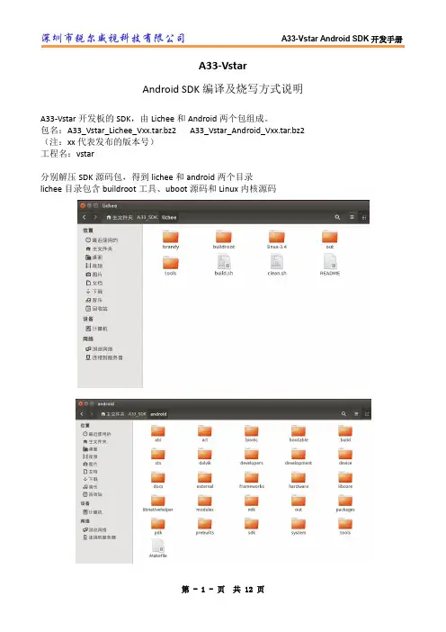
A33-VstarAndroid SDK编译及烧写方式说明A33-Vstar开发板的SDK,由Lichee和Android两个包组成。
包名:A33_Vstar_Lichee_Vxx.tar.bz2 A33_Vstar_Android_Vxx.tar.bz2 (注:xx代表发布的版本号)工程名:vstar分别解压SDK源码包,得到lichee和android两个目录lichee目录包含buildroot工具、uboot源码和Linux内核源码系统配置文件路径:lichee/tools/pack/chips/sun8iw5p1/configs/vstar/sys_config.fexAndroid工程路径:android/devices/softwinner/vstarlichee源码编译进入lichee目录,执行$ ./build.sh config依次选择:0 0 3首次编译,需要导入vstar方案的内核配置,进入linux3.4目录,执行:$ cp a33_vstar_defconfig .config退回到lichee目录,再执行$ ./build.sh即完成一次编译编译完成:Android源码编译编译完lichee源码后,新建一个终端,切换至android目录,执行$ . build/envsetup.sh#导入环境变量$ lunch#选择工程,这里选择15$ extract-bsp#拷贝内核和模块到android中$ make -j8 #多线程编译编译完成后,在android/out/target/product/vstar/目录下生成boot.img recovery.img system.img编译完成后,打包固件$ pack固件位置:lichee/tools/pack/sun8iw5p1_android_vstar.img在Linux系统烧写固件按照LiveSuit_For_Linux安装包中的教程安装LiveSuit,根据本机的系统位数选择安装32位或64位版本。
深圳市锐尔威视科技有限公司A33-Vstar串口使用说明串口复用说明:由于UART0的2根线和TF卡的其中2根线是复用的(是A33芯片决定的),所以在开发过程中,UART0的Debug和模式和TF卡只能2选一,默认是关闭UART0调试,使用TF卡。
打开UART0调试模式:Android系统:打包时使用pack -d 命令,生成的固件名为:sun8iw5p1_android_vstar_card0.img此时不能使用TF卡Linux系统:修改lichee/tools/pack/chip/sun8iw5p1/config/vstar/sys_config.fex,搜索“mmc0”将sdc_used = 1 改为sdc_used = 0,重新打包固件此时不能使用TF卡修改Debug的级别修改lichee/tools/pack/chip/sun8iw5p1/config/vstar/default/env.cfg将loglevel=4 改为loglevel=7 或9数值越低,表示打印的log越少;数值越高,表示打印的log越多重新打包固件即可更改调试串口为UART2:Android系统:修改lichee/tools/pack/chip/sun8iw5p1/config/vstar/default/env.cfg将console=ttyS0,115200 改为console=ttyS2,115200重新打包固件Linux系统:修改lichee/tools/pack/chip/sun8iw5p1/config/vstar/default/env.cfg将console=ttyS0,115200 改为console=ttyS2,115200进入文件系统目录buildroot/target/dragonboard/rootfs修改/etc/inittab文件将ttyS0::respawn:/sbin/getty -n -l/bin/autologin -L ttyS0 115200 vt100 # GENERIC_SERIAL改成ttyS2::respawn:/sbin/getty -n -l/bin/autologin -L ttyS2 115200 vt100 # GENERIC_SERIAL重新编译dragonboard、打包固件第 - 1 - 页共 1 页。

目录产品简介 (1)产品特性 (2)规格 (3)APP功能介绍 (4)4.1界面简介 (4)4.2功能介绍 (5)4.2.1设置 (5)4.2.2超温告警 (6)4.2.3界面重置 (7)4.2.4拍照 (7)4.2.5录像 (8)4.2.6图库 (8)4.2.7色板 (9)4.2.8区域测温 (11)4.2.9显示模式 (11)4.2.10融合偏移调整 (14)4.2.11图像锁定和镜像 (14)4.2.12高温速查 (15)4.2.13温度锁定 (15)使用注意事项 (17)双视场手机红外热成像仪仪采用像元间距小、高分辨率的工业级红外探测器,搭配3.2mm 镜头,是一款高精度快响应的便携红外热成像分析仪,同时应用了一款可见光的相机用以辅助红外成像,相比较单红外的产品可以更加清晰的显示出被测物体。
产品轻巧便携、即插即用,配合定制专业级热像分析APP,可以连接安卓手机对目标物体进行红外观测及测温。
∙优质光学镜头搭配高分辨率红外热成像,可见光数字相机采用640x480辅助成像,成像效果出色;∙相比较传统的手机热像仪,更多支持可见光模式、多种可见光和红外融合模式的测温,图像效果更加清晰细腻;∙轻巧便携,配合手机APP使用,随时随地进行专业热成像分析;∙测温范围广:-15℃~600℃;∙支持高温警报,自定义警报门限值;∙支持显示自定义温度区间画面,高温区域显示使用场景众多;∙支持高低温追踪;∙支持添加点、线、矩形框进行区域测温,线和矩形框支持高低温追踪和高温报警;∙铝合金外壳,坚固耐用。
规格红外热成像分辨率256x192160x120工作波长8~14μm帧率25HzNETD<50mK@25℃镜头 3.2mm视场角56°x42°35°x27°测温范围-15℃~600℃测温精度±2℃或读数的±2%可见光分辨率640x480帧率25Hz软件功能(APP)温度测量支持高低温自动追踪、中心点测温、点测温、区域测温、线测温,温度范围查看图像显示模式支持可见光模式,多种可见光和红外融合模式,单红外模式显示。

USER ’S INSTRUCTIONS使用说明书使用产品前请仔细阅读本使用说明书,并请妥善保管数显折射仪目录前言 (1)一、概述 (2)二、产品结构 (2)三、产品特点 (2)四、技术参数 (3)五、仪器安装 (3)六、使用说明 (3)1、清洁棱镜 (3)2、校准 (3)3、测量 (3)4、关机 (3)5、清洗 (4)七、维护保养 (4)九、保修声明 (4)十、开箱检查 (4)十一、装箱清单 (5)前言感谢您选择力辰科技数显折射仪,为获得更好的使用体验,请认真阅读本使用说明书,并遵守安全操作规范!请妥善保管本使用说明书以便需要时查阅!注意事项:请确保只有受过相关训练的人员才能操作使用本仪器。
请遵守安全规范、人身安全和事故防止等相关规范。
每次使用前请注意检查仪器和配件确保无损。
高温、低温待测液进行测量时,先放入棱镜座中,等待约20秒,使棱镜座充分导热后再测量,防止出现误差。
每一种溶液测试完以后,请用蒸馏水洗净样品槽,并用绒布擦拭干净,请勿使用硬质材料擦拭样品槽,以免划伤棱镜表面。
请根据处理介质的种类,选择合适的防护装置。
处理有毒、易挥发介质时,请在合适的通风橱中进行。
如待测液体具有腐蚀性,请在测量完成后,请立即进行清洗,避免腐蚀性溶液对棱镜和金属表面的持续损伤。
避免使产品接触过多的灰尘、强大的震动以及温度骤变。
请保持取液管和擦镜布的清洁干燥。
如长时间不用,请取出电池,将折射仪放置在干燥、无尘、无腐蚀性气体环境中保存。
一、概述数显折射仪,也称为数显糖度仪,数显浓度仪,水果糖度计。
具有广泛的衡量范围,适用于测量各类果汁、食品、饮料以及某些化学品或工业溶剂如切削油、清洗液和防冻剂等。
二、产品结构:1、LCD显示:显示测量值Brix(%),电量及温度。
2、样品槽:样品槽为新型合金,底部是玻璃棱镜。
3、“开始”键:按此键开始测量,长按两秒关机。
4、“归零”键:用于测量前调零。
5、“背光”键:用于开关液晶背光。
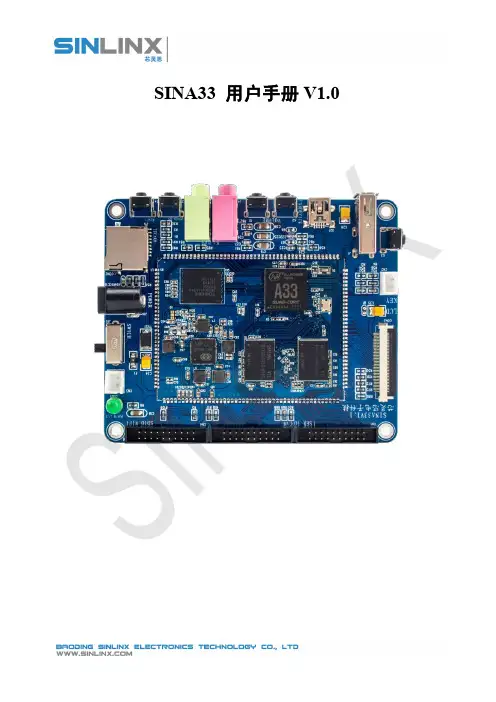
SINA33用户手册V1.0目录SINA33用户手册V1.0 (1)一、前言 (5)二、烧写指南 (6)(一)烧写介绍 (6)(二)通过USB烧写到EMMC (6)1.将开发板的USB OTG与PC相连 (6)2.打开烧写软件PhoenixSuit (6)3.按住开发板的vol按键后,打开电源开关,快速并多次点击power按键,直到出现下图所示为止 (7)三、编译环境搭建 (8)(一)PC上的操作系统 (8)(二)安装编译环境 (8)1.安装相应的库支持 (8)2.安装JAV A6-JDK (8)四、编译Android系统 (10)(一)解压Android源码 (10)(二)编译lichee目录 (11)(三)编译android目录 (12)五、系统的订制 (18)(一)系统配置文件 (18)(二)系统配置文件说明 (18)1.配置文件说明 (18)2.配置文件修改后的编译 (18)六、系统(System) (19)(一)[platform] (19)(二)[target] (19)(三)[pm_para] (19)(四)[card_boot] (20)(五)[card_boot0_para] (20)(六)[card_boot2_para] (20)(七)[twi_para] (21)(八)[uart_para] (21)(九)[jtag_para] (22)(十)[clock] (22)七、I2C总线 (23)(一)[twi0_para] (23)(二)[twi1_para] (23)(三)[twi2_para] (23)(四)[twi3_para] (24)八、串口(UART) (25)(一)[uart_para0] (25)(二)[uart_para1] (25)(三)[uart_para2] (26)(四)[uart_para3] (26)(五)[uart_para4] (27)(六)[uart_para5] (27)(七)[uart_para6] (27)(八)[uart_para7] (28)九、SPI总线 (29)(一)[spi0_para] (29)(二)[spi1_para] (29)(三)[spi2_para] (30)(四)[spi3_para] (30)(五)[spi_devices] (30)(六)[spi_board0] (31)十、电容屏(capacitor tp) (32)(一)[ctp_para] (32)十一、触摸按键(touch key) (33)(一)[tkey_para] (33)十二、马达(motor) (34)(一)[motor_para] (34)十三、显示初始化(disp init) (35)(一)[disp_init] (35)十四、LCD屏0 (37)(一)[lcd0_para] (37)十五、LCD屏1 (41)(一)[lcd1_para] (41)十六、HDMI (42)(一)[hdmi_para] (42)十七、摄像头(CSI) (43)(一)[csi0_para] (43)(二)[csi1_para] (43)十八、SD/MMC (48)(一)[mmc0_para] (48)(二)[mmc1_para] (49)(三)[mmc2_para] (49)(四)[mmc3_para] (50)十九、SIM卡 (52)(一)[smc_para] (52)二十、USB控制标志 (53)(一)[usbc0] (53)(二)[usbc1] (54)(三)[usbc2] (55)二十一、USB Device (56)(一)[usb_feature] (56)(二)[msc_feature] (56)二十二、重力感应(G Sensor) (57)(一)[gsensor_para] (57)二十三、WIFI (58)(一)[wifi_para] (58)(二)sdio接口wifi rtl8723as demo (58)(三)usb接口wifi rtl8188eu demo (59)二十四、3G (60)(一)[3g_para] (60)二十五、gyroscope (61)(一)[gy_para] (61)二十六、光感(light sensor) (62)(一)[ls_para] (62)二十七、罗盘Compass (63)(一)[compass_para] (63)二十八、蓝牙(blueteeth) (64)(一)[bt_para] (64)二十九、数字音频总线(I2S) (65)(一)[i2s_para] (65)三十、数字音频总线(pcm) (66)(一)[pcm_para] (66)三十一、数字音频总线(S/PDIF) (67)(一)[spdif_para] (67)三十二、喇叭控制 (68)(一)[audio_para] (68)三十三、红外(ir) (69)(一)[ir_para] (69)三十四、PMU电源 (70)(一)[pmu_para] (70)一、前言A33是珠海全志科技最新推出的四核处理器。

目录1、概述2、注意事项及安全保养4、性能指标5、产品描述5.1、结构介绍6、常规操作说明8、“图像”子菜单介绍9、“调色板”子菜单介绍10、“发射率”子菜单介绍11、“设置”子菜单介绍1234468910135.2、显示内容说明55.3、按键描述68.1、查看图像89.1、调色板说明910.1、发射率说明1010.2、发射率设置1110.3、普通材料的发射率值1211.1、时间设置1411.2、最高/最低温度光标的开启与关闭158.2、删除图像81.概述本产品是表面温度测量和实时热图像相结合的红外热成像仪。
传统的红外测温仪需要逐一测量每个部件,而红外热成像仪则无需如此,从而节省了时间。
潜在问题可清晰地显示在彩色显示屏上,而且通过中心点测量光标能快速准确地定位并测量目标物体的温度。
为了增加辨识度,该产品还配有一个可见光摄像机。
热图像和可见光图像都可以保存到本设备中,通过USB读取图像或将其保存至电脑用于生成报告和打印。
该产品广泛应用于医疗、消防、考古、交通、农业、地质、能源、治炼、电子制造等领域,是电工和维护技术人员的理想之选,可用于快速找到问题区域。
以下几大功能增加了产品的测量准确性和可用性:可以调节辐射系数来提高半反射表面物体测量的准确性。
最高温度和最低温度光标可将用户引导至热图像温度最高和最低的区域。
具有可选调色板。
9.2、调色板应用103、读取图像27、“图像重合”菜单介绍74.性能指标2.注意事项及安全保养为确保正确的使用本产品,请仔细阅读使用说明:切勿私自拆卸和改装本产品。
不要在易燃易爆、潮湿或腐蚀性环境下使用本产品。
本产品含有精密电子和敏感光学器件,请勿撞击和跌落,以免造成损坏。
本产品的外壳用湿布或弱肥皂清洁,不要使用研磨剂、异丙醇或溶剂清洁,镜头和屏幕使用专业的光学镜片清洗剂。
本产品工作时每隔几秒会有轻微的咔咔声,这是镜头捕捉图像的正常现象。
内置可充电1800mAh电池3.2英寸全视角TFT显示屏220×160固定调焦方式9Hz彩虹/铁红/冷色/白热/黑热内置3G(可存储图像2万张以上)JPG可选择:5分钟/20分钟/不自动关机Micro USB 2.0显示屏型号VICTOR 326红外热图像分辨率可见光图像分辨率视场角最短焦距热灵敏度温度测量范围测量精度发射率热图像帧率波长范围调色板储存介质图像格式自动关机时间产品尺寸(长×宽×高)工作温度存储温度相对湿度640×480(30万像素)LCD分辨率320×24027°x35°0.15米0.07℃-20℃至300℃(-4°F至572°F)0.01至1.00可调8μm至14μm 140mm×80mm×28mm 208g0℃至45℃-20℃至60℃<85%RH开机稳定测温时间0分钟工作时间2-3小时产品重量电池类型USB±2℃或±2% 3.读取图像使用USB线连接电脑,可读取图像或将其保存至电脑中。

PISO-P32C32/P32A32User ManualWarrantyAll products manufactured by ICP DAS are warranted against defective materials for a period of one year from the date of delivery to the original purchaser.WarningICP DAS assume no liability for damages consequent to the use of this product. ICP DAS reserves the right to change this manual at any time without notice. The information furnished by ICP DAS is believed to be accurate and reliable. However, no responsibility is assumed by ICP DAS for its use, nor for any infringements of patents or other rights of third parties resulting from its use.CopyrightCopyright 1999 by ICP DAS. All rights are reserved. TrademarkThe names used for identification only may be registered trademarks of their respective companies.Tables of Contents1.Linux Software Installation (3)1.1 L INUX D RIVER I NSTALLING P ROCEDURE (3)1.2 L INUX D RIVER U NINSTALLING P ROCEDURE (3)2.Static Libary Function Description (4)2.1T ABLE OF E RROR C ODE AND E RROR S TRING (5)2.2F UNCTION D ESCRIPTIONS (5)2.3D IGITAL I/O FUNCTIONS (5)2.3.1 PIODA_GetDriverVersion (5)2.3.2 PIODA_GetLibaryVersion (6)2.3.3 PIODA_Open (6)2.3.4 PIODA_Close (6)2.3.5 PIODA_DriverInit (7)2.3.6 PIODA_Digital_Output (7)2.3.7 PIODA_Digital_Input (8)3.PISO-P32C32/P32A32 Demo Programs (9)3.1 D EMO CODE “PORT.C” (9)3.2 D EMO CODE “PORT_A.C” (9)1.Linux Software InstallationThe PISO-P32C32/P32A32 can be used in linux kernel 2.4.X and 2.6.X. For Linux O.S, the recommended installation and uninstall steps are given in Sec 1.1 ~ 1.21.1 Linux Driver Installing ProcedureStep 1: Copy the linux driver “ixpio-0.20.4.tar.gz”(or the later driver version) in the directory “NAPDOS\Linux” of the companion CD to the linuxhost that you want to install driver.Step 2: Decompress the tarball “ixpio-0.20.4.tar.gz”.Step 3: Type `cd' to the directory containing the package's source code and type ./configure' to configure the package for your system.Step 4: Type `make' to compile the package.Step 5: Type `./ixpio.inst' to install the PIO/PISO driver module and build the device file “ixpioX” in the device directory “/dev” automatically.1.2 Linux Driver Uninstalling ProcedureStep 1: Type `cd' to the directory containing the package's source code.Step 2: Type `./ixpio.remove' to remove the PIO/PISO driver module.2. Static Libary Function DescriptionThe static libary is the collection of function calls of the PIO-DIO cards for linux kernel 2.4.x and 2.6.x system. The application structure is presented as following figure. The user application program developed by C(C++) language can call library “libpio.a” in user mode. And then static libary will call the module ixpio to access the hardware system.Figure 2.12.1 Table of ErrorCode and ErrorStringTable 2.1ErrorCode Error ID Error String0 PIODA_NOERROR OK ( No error !)1 PIODA_MODULE_NAME_GET_ERROR Module name can't getfrom file /proc/ixpio/ixpio5 PIODA_DIGITAL_OUTPUT_ERROR Digital output error6 PIODA_DIGITAL_INPUT_ERROR Digital input error2.2 Function DescriptionsTable 2.2Function DefinitionWORD PIODA_GetDriverVersion(void);WORD PIODA_GetLibaryVersion(void);int PIODA_Open(char *dev_file);WORD PIODA_Close(WORD fd);WORD PIODA_DriverInit(WORD);WORD PIODA_Digital_Output(WORD, WORD, byte);WORD PIODA_Digital_Input(WORD, WORD, WORD *);2.3 Digital I/O FUNCTIONS2.3.1 PIODA_GetDriverVersion•Description:To show the version number of PIO/PISO linux driver.•Syntax:WORD PIODIO_GetDriverVersion(Void)•Parameter:None•Return:The code “PIODA_NOERROR”(Please refer to "Section 2.1 Error Code")2.3.2 PIODA_GetLibaryVersion•Description:To show the version number of PIO/PISO linux static libary..•Syntax:WORD PIODIO_GetLibaryVersion(void)•Parameter:None•Return:The code “PIODA_NOERROR”(Please refer to "Section 2.1 Error Code")2.3.3 PIODA_Open•Description:To open device file.•Syntax:int PIODIO_Open(char *dev_file)•Parameter:dev_file : The path of device file•Return:The file descriptor of device file. If the file descriptor < 0, it means thatopen device file failure.2.3.4 PIODA_Close•Description :To close device file.•Syntax :Word PIODIO_Close(WORD fd)•Parameter :fd : The file descriptor of device file that get from function PIODIO_Open •Return:The code “PIODA_NOERROR”(Please refer to "Section 2.1 ErrorCode").•Description :To allocates the computer resource for the device. This function must be called once before applying other PIODA functions.•Syntax :WORD PIODA_DriverInit(WORD fd)•Parameter :fd : The file descriptor of device file that get from function PIODIO_Open •Return:The code “PIODA_MODULE_NAME_GET_ERROR” or“PIODA_NOERROR”(Please refer to "Section 2.1 Error Code").2.3.6 PIODA_Digital_Output•Description :This subroutine sends the 8 bits data to the specified I/O port.•Syntax :WORD PIODA_Digital_Output(WORD fd, WORD port, byte data);•Parameter :fd : The file descriptor of device file that get from functionPIODIO_Open.port : The value of DO port . Please refer to “Table 2.3” DI/O port ID.Table 2.3PISO-P32C32 Port ID PISO-P32A32 Port ID DI/O PortPISOP32C32_DIOA PISOP32A32_DIOA DI/O 0 ~ DI/O 7 PISOP32C32_DIOB PISOP32A32_DIOB DI/O 8 ~ DI/O 15 PISOP32C32_DIOC PISOP32A32_DIOC DI/O 16 ~ DI/O 23 PISOP32C32_DIOD PISOP32A32_DIOD DI/O 24 ~ DI/O 31 PISOP32C32_DIO_ALL PISOP32A32_DIO_ALL DI/O 0 ~ DI/O 31data : 8 bits data.•Return:If returned value = PIODA_NOERROR, it means that sending data toI/O port successfully. Otherwise, please refer to "Section 2.1 ErrorCode".2.3.7 PIODA_Digital_Input•Description :This subroutine reads the 8 bits data from the specified I/O port.•Syntax :WORD PIODA_Digital_Input(WORD fd, WORD port, WORD *di_data);•Parameter :fd : The file descriptor of device file that get from functionPIODIO_Open.port : The value of DI port. Please refer to “Table 2.3” DI/O port ID.di_data : A variable address used to storage the 8 bits input data.•Return:If returned value = PIODA_NOERROR, it means that reading data fromDI port successfully. Otherwise, please refer to "Section 2.1 Error Code".3. PISO-P32C32/P32A32 Demo ProgramsAll of demo programs will not work normally if PIO/PISO linux driver would not be installed correctly. During the installation process of PIO/PISO linux driver, the install-scripts “ixpio.inst” will setup the correct kernel driver. After driver(version 0.20.4 or the later driver version) compiled and installation, the related demo programs, development library and declaration header files for different development environments are presented as follows.Table 3.1Driver Name Directory PathFileNameDescription Include piodio.h PIO/PISO library header Lib libpio.a PIO/PISO static libaryport.cDigital input and outputdemoixpio-0.20.4Examples/pisop32c32Examples/pisop32a32port_a.c DI and DO demo with libary 3.1 Demo code “port.c”This demo program is used to output digital from DO 0 ~ 31, input digital data from DI 0 ~ 31.3.2 Demo code “port_a.c”This demo program coded by using the static library “libpio.a”. It is used to output digital from DO 0 ~ 31 , input digital data from DI 0 ~ 31.。
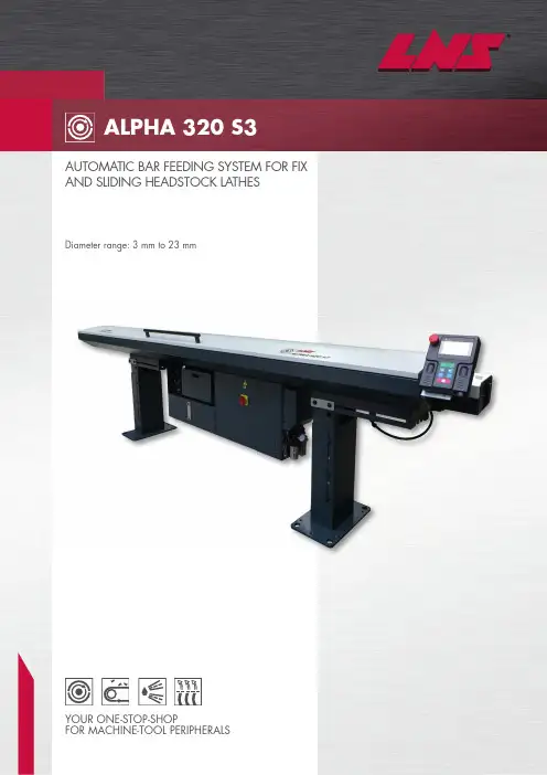
Diameter range: 3 mm to 23 mmAUTOMATIC BAR FEEDING SYSTEM FOR FIX AND SLIDING HEADSTOCK LATHESYOUR ONE-STOP-SHOP FOR MACHINE-TOOL PERIPHERALS2INCREASE YOUR PRODUCTIVITYWith the Alpha 320 S3, LNS is offering a cost-effective solution for feeding bar material for fix and sliding headstock. The Alpha 320 S3 is designed to withstand any production process at optimum speeds. High-quality guidance, low noise emissions and effective vibration dampening are ensured by wear-resistant guide channels. In terms of its price-performance ratio, the Alpha 320 S3 is an ideal bar feeding system for the diameter range from 3 mm to 23 mm. MOBILE REMOTE CONTROL WITH TOUCHSCREENThe remote control with a colour, operator-friendly touchscreen (HMI) allows an easy setting and interface via menu-controlled icons, the bar feeder and the lathe. This ensures that the production process can be performed reliably and efficiently.The HMI is impressive due to its simple layout and ease of operation. It displays setting parame-ters, alarm descriptions and operating faults.SIMPLE AND RAPID CONVERSIONBar diameters on the side load rack of the bar feeder are changed over by a centrally controlled, manual setting using an adjusting lever.A position scale enables clear visualisation of the setting and prevents setting errors.• Two minutes for a diameter changeover in the area of the guide channels• Ten minutes for a diameter changeover of all guiding elementsPERFECT BAR GUIDANCEThe guide channels made from cast polyurethane are essential components for achieving opti-mum performance and withstanding the highest loads.The housings for the Alpha 320 S3's guide channels consist of a solid steel structure in order to dampen vibrations during the production processes. Combined with the servo-controlled drive, the bar material is guided through the entire machining process accurately and reliably.The quick-change guiding elements are secured in place by fixing pins. For a full diameter change-over, the elements can be replaced quickly and easily without needing to use any tools. The pusher can be released simply and quickly by unlocking the manual levers.Settings can be easily configured in less than one minute.The operator simply enters theparameters for the material into the HMI:• Bar diameter• Size of guide channel• Feeding lengthThe HMI automatically sets thefollowing parameters:• Feed force• Feed rate• Feeding length3POWERFUL REMNANT EXTRACTION SYSTEM WITH SELF-CEN-TRING CLAMPING JAWSThe sturdy design of the system not only provides enough force to insert and remove the material, but also ensures that the material can be reliably detected thanks to the mon-itoring system. This prevents failure during insertion or when the remnant is withdrawn. To optimally clamp bars with smaller diameters, soft materials or thin-walled tubes, the clamping force of the self-centring clamping jaws can be set using a pressure regulator.INCREASED RELIABILIT Y DURING OPERAT ION AT OPT IMUM SPEEDS The tried-and-tested LNS connection with telescopic tube ensures improved bar guidance in the area between the bar feeder and the lathe's spindle entry point.This connection can be used to move the headstock forward to finish parts without the risk of the bar being able to swing out freely.The system is designed such that corresponding reduction tubes can be inserted into the telescopic tube. These tubes are used as spindle reduction tubes at the same time.The inside diameters of the reduction tubes are adapted to the diameter of the bar feeder's guide channels. Vibrations and oscillations of the bar are reduced in the critical area and for the area where there is usually no guidance.This allows the system to run at optimum speeds for improving tolerances, enables the surface quality to be improved and the life time of the tools to be extended.FRONT RESTPneumatically actuated, the oil-flooded, two-position front rest with V-shaped guiding elements dampens the residual vibrations of the rotating bar material.When closed, the front rest remains at the bar itself. When open, the front rest holds the pusher when plunging into the lathe's spindle.The blow-off ring supplied eliminates the residual oil on the bars.MAXIMUM CONVENIENCEAs standard, the Alpha 320 S3 is equipped with a longitudinal movement system which is moni-tored by a safety switch. This device facilitates access to the lathe for maintenance or repair work.For the lathes which operate with /without guide bush, an adjustable two-positions movement system can optionally be supplied.S ubjecttom o d i fi c a t i o n s / A l p h a 320 S 3 – E N / 11-2016FEATURES AND BENEFITS • Hydrobar ® technology, hydrodynamic guidance of the bar material • Two minutes for a diameter changeover in the area of the guide channels • Ten minutes for a full guiding element changeover • Guide channels and pusher with quick-change system• Ergonomic control panel with colour touchscreen for ease of operation • Capacity: Side load rack, 270 mm • Compact, sturdy design • Actuated via servomotor• A utomatic setting of the feed force and speed when the material diameter is input • Automatic, oil-flooded, two-position front rest • Remnant ejection system • Simple manual diameter setting for the bar selection• T ried-and-tested LNS connection with telescopic tube for machines with sliding headstock • Can be fitted to the right or left-hand side depending on the lathe model • Longitudinal movement system, 430 mm• T he following are available as an option for lathes which operate with or without guide bush 2-Positions longitudinal movement, adjustable up to 270 mm 2-Positions longitudinal movement 350 mm YOUR ONE-ST OP-SHOP FOR MACHINE-T OOL PERIPHERALS LNS provides a full range of bar feeders, chip conveyors, coolant manage-ment systems and air filtration systems which is second to none on the market. We are known in the industry for the solid expertise we have gained over several decades in an exceptionally wide range of applications, our excellent customer service and technical support. This support is ensured by highly qualified technicians who are available at key locations throughout2-Positions longitudinal movement 350 mm。

Ref.Qty Part No.Description BezeichnungDescription112665595No Hand Hold Decal Warnungsschild Auto collant 26679150No Step Decal WarnungsschildAuto collant31211274Eagle, 80 mm Cascade Adler, 80 mm Aigle Cascade, 80 mm 42211275Eagle, 160 mmCascade Adler, 160 mmAigle Cascade, 160 mmDecalsWarnungsschildAuto CollantBase Unit Group RahmengruppeCommon Parts / Einfache komponenten / Pièces communes Ref.Qty.Part No.Description BezeichnungDescription 624211689Capscrew, M12 x 3074q 209741Rod End88768303Capscrew, M10 x 35Kopfschraube, M12 x 30KolbenendeKopfschraube, M10 x 35Vis à tête, M12 x 30ChapeVis à tête, M10 x 359Buchse Bague 108q 210490Retainer Half Ring 4q 210489Rod End Anchor Anker Ancrage 114210140Bearing Retainer BuchseBague1241312787375Capscrew, M8 x 20211128Capscrew, M16 x 30Kopfschraube, M8 x 20Kopfschraube, M16 x 30Vis à tête, M8 x 20Vis à tête, M16 x 30q Included in kit 213856 / Enthalten im Dichtsatz 213856 / Inclus dans le kit de service 213856Cylinder T-bar Baseplate L.Basepl. R.Bearing kit Frame Zylinder Schiene Grundplatte L.Grundpl. R.Distanzsatz Rahmen Base Unit Group Rahmengruppe Groupe batiVérin Barre Pl. de base G.Pl. de base D.Kit de Entr.Bati 2138922139042170092173722173732291281050Ref.1Ref.2Ref. 3Ref. 4Ref.5II Frame Cylinder213904 ZylinderVérinCommon Parts / Einfache komponenten / Pièces communesRef Qty Partno.Description Bezeichnung Description11213905Cylinder Shell Zylinderrohr Tube de vérin214157-740Rod Kolbenstange Tige de vérin31213783End Cap Deckel Bague48768208Capscrew, M8 x 25Kopfschraube, M8 x 25Vis à tête, M8 x 2551v209809Bearing Lager Roulement61787375Capscrew, M8 x 20Kopfschraube, M8 x 20Vis à tête, M8 x 2071212452Retainer Buchse Bague82v643379O-ring O-Ring Joint torique92v210050Back-up ring Stutzring Joint de protection101v212477Seal Dichtung Joint111v209808Seal Dichtung Joint122v214053O-ring, durometer O-Ring Joint torique131v562131Wiper Abstreifer Racleurv Included in Service Kit 210090 / Enthalten im Dichtsatz 210090 / Inclus dans le kit de service 210090III Hydraulic Group212980 Hydraulikleistunggruppe212983Système HydrauliqueST AMPEDVALVERef.Qty Partno.Description Bezeichnung Description 11v212962Valve Assembly Ventilzusammenb.Ensemble de valve26768208Capscrew, M8 x 25Kopfschraube, M8 x 25Vis à tête, M8 x 2532768797Capscrew, M8 x 40Kopfschraube, M8 x 40Vis à tête, M8 x 4042768800Capscrew, M8 x 60Kopfschraube, M8 x 60Vis à tête, M8 x 60511214053O-Ring O-Ring Joint torique61212974Manifold Verteilerblock Bloc hydraulicv See Valve page for parts breakdown, part number stamped on valve.s Includes items 5,6 / Ref. 5,6 enthalten / Ref. 5,6 inclusv Includes items 1-5 / Ref. 1-5 enthalten / Ref. 1-5 inclusVariable components / Variable Komponenten / Pièces différentesRef.Qty.Part No.Description BezeichnungDescription 212980Hydraulic Group Hydraulik Gruppe Syst. Hydraulique 11214405Relief Valve Druckbegr. Ventil Valve de décharge 23215756Piston KolbenPistonCommon Parts / Einfache komponenten / Pièces communes Ref.Qty Part No.DescriptionBezeichnung Description 31214291Valve Body Ventil Gehause Corps de clapets 44682170Seal KitDichtsatz Kit de service 51210266Flow Divider/Combiner Mengenteiler Repart de débit 61679992Seal Kit DichtsatzKit de service 73209847Check Valve Rückschlagventil Valve anti-retour 81609234Fitting, 4Verschraubung, 4Raccord, 4Fitting groups / Hydraulische Verschraubungen / Raccords HydrauliqueRef.QtyPart No.Description Bezeichnung Description 212978Fitting group Verschr. Gruppe Groupe raccord 93604511Fitting Verschraubung Raccord 101605743Fitting Verschraubung Raccord 1AdaptorVerschraubungRaccordIncluded in Service Kit 211568 / Enthalten im Dichtsatz 211568 / Inclus dans le kit de service 211568Valve for Forkpositioners only / Ventil nur für Zinkenverstellgeräte / Valve pour les Ajusteurs de FourchesValve - Sideshifting , 212962Ventil - mit SeitenschubValve - avec Déplacement Lateral●☐☐☐●ForksGabelnFourchesRef.Qty Part No.Description Bezeichnung Description 114271-014-0736Arm, LH Arm, L.Bras, G.214272-014-0736Arm, RH Arm, R.Bras, D.Bolt-On Mounting Group , class 2211162Aufhängungsgruppe 211173Groupe d’ AccrochageRef.Qty Part No.DescriptionBezeichnungDescriptions 211162Upper Mounting Group Aufhängungsgr., oben Groupe d‘ Accrochage, sup. l 211173Lower Mounting Group Aufhängungsgr., unten Groupe d‘ Accrochage, inf.12210491Upper HookHaken, obenCrochet, supérieur 24768577Capscrew, M20 x 35Kopfschraube, M20 x 35Vis à tête, M20 x 3531212999Center KeyKeilClavette42211129Capscrew, M16 x 35Kopfschraube, M16 x 35Vis à tête, M16 x 3552675968Lower HookHaken, untenCrochet, inférieur 64211128Capscrew, M16 x 30Kopfschraube, M16 x 30Vis à tête, M16 x 3074211179Washer, M16UnterlegscheibeRondelles Includes items 1–4 / Ref. 1-4 enthalten / Ref. 1-4 inclus l Includes items 5–7 / Ref. 5-7 enthalten / Ref. 5-7 inclusCL0329.ill。
A33环境搭建编译手册A33环境搭建编译手册说明目录Ubuntu安装 4制作Ubuntu的USB启动盘 4安装Ubuntu 6配置ssh 15配置vim 15开启Ubuntu图形界面的root权限 16配置WINDOWS可用XRDP远程桌面 17 搭建安卓编译开发环境 18JAVA库下载、安装与配置 19编译器下载、安装与配置 19Uboot镜像制作工具下载安装 20安装编译环境需要的库 20编译指南 21编译内核 21编译lichee 22编译brandy 23编译Android 24Android打包 25Ubuntu安装制作Ubuntu的USB启动盘登陆,下载USB启动盘制作工具找到DOWNLOAD UUI,下载下载后,插入U盘运行(Universal-USB-Installer-1.9.5.9.exe 目前在技术部服务器有提供)同意协议,下一步如下图设置,Step1:选着Linux发行版Step2:选择ubuntu镜像所在的路径Step3:选择插入的U盘Step4:默认选项确认制作完成安装Ubuntu插入制作好的U盘到电脑,重启,按F12(根据实际情况)进入启动选项菜单,选择从U盘启动。
一路不用操作,默认的“Try Ubuntu without Installing”直至进入Ubuntu试用系统,双击Install Ubuntu图标开始安装,如下图选择中文勾选下载更新,勾选安装第三方软件询问安装类型,建议使用其他选项,可以更好的进行自定义选择要安装的硬盘进行分区,这里安排是:500G大小的硬盘分区挂载点容量第一个分区/(根分区)30G第二个分区SWAP4G第三个分区/opt466G(即剩余的容量)这么处理,考虑到以后开发相关的都放在opt上,如需重装、升级操作系统,无需破坏开发的资料操作如下,点击选择目标硬盘的空闲空间,点击添加如下图设置第一个分区重复上一步,再添加第二个分区重复上一步,再添加第三个分区选择安装启动引导器的设备为硬盘的引导区,点击现在安装接下来设置时区设置键盘布局设置账户信息和计算机信息等待安装完成直至提示安装完成,点击重启重启之后进入系统,弹出更新管理器,选择不升级为14.04,选择安装更新更新完重启系统配置sshCtrl+Alt+T打开终端自动下载配置sshsudo apt-get install ssh在Windows下使用PuTTY即可使用SSH远程登录配置vimvm是vi的升级版本自动下载配置vimsudo apt-get install vim开启Ubuntu图形界面的root权限快捷键打开终端Ctrl+Alt+T获取root权限输入sudo -s 输入普通用户登陆的密码,回车获得root权限修改配置文件/etc/lightdm/lightdm.conf试用vim打开或者试用gedit打开vim /etc/lightdm/lightdm.conf或:gdit /etc/lightdm/lightdm.conf编辑后文档内容如下(添加下面加底纹内容):[SeatDefaults]greeter-session=unity-greeteruser-session=Ubuntugreeter-show-manual-login=trueallow-guest=false设置root用户密码sudo passwd root重启后选择登陆root登陆帐号注:下文开始,如无特殊说明都是在root用户下进行操作配置WINDOWS可用XRDP远程桌面打开终端,自动配置安装xrdp和vncapt-get install xrdp vnc4server tightvncserver打开要远程登录用户的home目录,root用户即/rootcd ~创建.xsession文件echo "gnome-session --session=ubuntu-2d" > .xsession重启xrdp/etc/init.d/xrdp restart在Windows下使用远程桌面连接(请根据实际情况输入ip)输入账号密码即可登录搭建安卓编译开发环境JAVA库下载、安装与配置登陆:/technetwork/java/javase/downloads/jav a-archive-downloads-javase6-419409.html下载jdk-6u45-linux-x64.bin (技术部服务器上有保存)需要注意的是,现在官方网站上最新的版本的JDK7,但是这个这个版本是不能用于Android的编译的,一定要去下载JDK6下载后,修改权限chmod 777 jdk-6u45-linux-x64.bin./jdk-6u45-linux-x64.bin安装后产生jdk1.6.0_45目录,把它拷贝到/opt/lib/jvm/jdk6/下面设置环境变量vim /etc/environment添加上底纹部分内容PATH="/usr/local/sbin:/usr/local/bin:/usr/sbin:/usr/bin:/sbin :/bin:/usr/games:/opt/lib/jvm/jdk6/jdk1.6.0_45/bin:/opt/lib/jvm/ jdk6/jdk1.6.0_45/jre/bin"JAVA_HOME=/opt/lib/jvm/jdk6/jdk1.6.0_45CLASSPATH=/opt/lib/jvm/jdk6/jdk1.6.0_45/libSource环境变量source /etc/environment查看Java版本验证安装,若能看到版本信息则一般安装完成java -version版本信息如下java version "1.6.0_45"Java(TM) SE Runtime Environment (build 1.6.0_45-b06)Java HotSpot(TM) 64-Bit Server VM (build 20.45-b01, mixed mode)Uboot镜像制作工具下载安装apt-get install uboot-mkimage安装编译环境需要的库apt-get install Git gnupg flex bison gperf build-essential zip curl libc6-dev libncurses5-dev:i386 x11proto-core-dev libx11-dev:i386 libreadline6-dev:i386 libgl1-mesa-glx-lts-trusty:i386 libgl1-mesa-dev g++-multilib mingw32 tofrodos Python-markdown libxml2-utils xsltproc zlib1g-dev:i386ln -s /usr/lib/i386-linux-gnu/mesa/libGL.so.1 /usr/lib/i386-linux-gnu/libGL.so编译器下载、安装与配置编译器下载、替换4.4版本apt-get install gcc-4.4 g++-4.4 g++-4.4-multilibmv -f /usr/bin/gcc /usr/bin/bak_gccmv -f /usr/bin/g++ /usr/bin/bak_g++ln -s /usr/bin/gcc-4.4 /usr/bin/gccln -s /usr/bin/g++-4.4 /usr/bin/g++测试一下gcc版本号gcc -v版本信息如下Using built-in specs.Target: x86_64-linux-gnuConfigured with: ../src/configure -v --with-pkgversion='Ubuntu/Linaro 4.4.7-1ubuntu2' --with-bugurl=file:///usr/share/doc/gcc-4.4/README.Bugs --enable-languages=c,c++,fortran,objc,obj-c++ --prefix=/usr --program-suffix=-4.4 --enable-shared --enable-linker-build-id --with-system-zlib --libexecdir=/usr/lib --without-included-gettext --enable-threads=posix --with-gxx-include-dir=/usr/include/c++/4.4 --libdir=/usr/lib --enable-nls --with-sysroot=/ --enable-clocale=gnu --enable-libstdcxx-debug --enable-objc-gc --disable-werror --with-arch-32=i686 --with-tune=generic --enable-checking=release --build=x86_64-linux-gnu --host=x86_64-linux-gnu --target=x86_64-linux-gnu Thread model: posixgcc version 4.4.7 (Ubuntu/Linaro 4.4.7-1ubuntu2)编译指南创建项目文件夹mkdir /opt/item_A33解压lichee.tar.gz压缩包tar -zxvf lichee.tar.gz -C /opt/item_A33/解压android.tar.gz压缩包tar -zxvf android.tar.gz -C /opt/item_A33/进入lichee目录cd /opt/item_A33/lichee编译内核source buildroot/scripts/mksetup.sh出现以下设置选项,请依照设置Welcome to mkscript setup progressAll available chips:0. sun8iw5p1Choice: 0All available platforms:0. android1. dragonboard2. linuxChoice: 0All available kernel:0. linux-3.4Choice: 0All available boards:0. evb1. maple2. redwood3. y24. y3Choice: 4编译licheemklichee编译过程INFO: ---------------------------------------- INFO: build lichee ...INFO: chip: sun8iw5p1INFO: platform: androidINFO: kernel: linux-3.4INFO: board: y3INFO: output: out/sun8iw5p1/android/y3INFO: ----------------------------------------INFO: build buildroot ...external toolchain has been installedINFO: build buildroot OK.INFO: build kernel ...INFO: prepare toolchain ...Building kernelCHK include/linux/version.hCHK include/generated/utsrelease.hmake[1]: “include/generated/mach-types.h”是最新的。
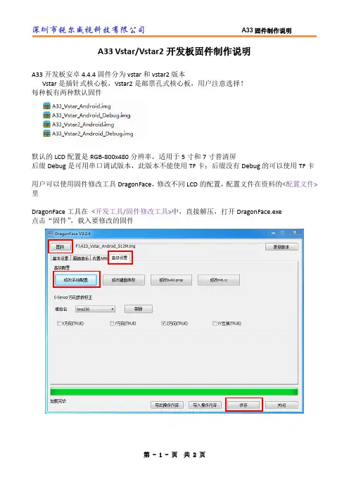
A33 Vstar/Vstar2开发板固件制作说明A33开发板安卓4.4.4固件分为vstar和vstar2版本Vstar是插针式核心板,Vstar2是邮票孔式核心板,用户注意选择!每种板有两种默认固件默认的LCD配置是RGB-800x480分辨率,适用于5寸和7寸普清屏后缀Debug是可用串口调试版本,此版本不能使用TF卡;后缀没有Debug的可以使用TF卡用户可以使用固件修改工具DragonFace,修改不同LCD的配置,配置文件在资料的<配置文件>里DragonFace工具在<开发工具/固件修改工具>中,直接解压,打开DragonFace.exe点击“固件”,载入要修改的固件等待载入完成,选择“高级设置”中的“修改系统配置”会弹出一个记事本文件,此文件就是sysconfig.fex将记事本文件的内容全部替换为相应LCD配置文件(sysconfig.fex)的内容,“保存”成新的固件,烧录到板上即可关于触摸屏:现有的CTP是5寸、7寸普清、7寸高清(RGB)、7寸高清(LVDS)、10.1寸其中5寸,7寸普清,7寸高清的IIC地址是0x3a,10.1寸的IIC地址是0x38用户编译SDK时,如要使用10.1寸,要修改lichee/linux3.4/drivers/input/touchscreen/ft5x/ft5x.c第149行,将0x3a,改成0x38重新编译lichee和android,打包固件2017.2月以前购买5寸屏的用户,也需要把地址改为0x38,之后购买的用户则不需要改关于1G内存配置:1G的内存是DDR3L类型,电压是1.35V(普通的DDR3是1.5V),只需改电压修改sysconf.fex的第58行dcdc5_vol = 1350。
A33System Configuration 说明书Co nf id e nt ia l文档履历版本号日期制/修订人制/修订记录V1.0 2013-04-03 初始版本V2.0 2014-05-30 updateC o n f i d en t i al目录A33.............................................................................................................................................. 1 1. 系统 . (6)1.1. [product] ................................................................................................................ 6 1.2. [platform] .............................................................................................................. 6 1.3. [target] ................................................................................................................... 6 1.4. [charging_type] ..................................................................................................... 6 1.5. [key_detect_en] ..................................................................................................... 6 1.6. [power_sply] .......................................................................................................... 7 1.7. [card_boot] ............................................................................................................ 7 1.8. [card_boot0_para] ................................................................................................. 7 1.9. [card_boot2_para] ................................................................................................. 8 1.10. [twi_para] .............................................................................................................. 9 1.11. [uart_para] ............................................................................................................. 9 1.12. [jtag_para] ............................................................................................................. 9 1.13. [clock] .................................................................................................................. 10 1.14. [pm_para] (10)2. SDRAM............................................................................................................................. 10 2.1. [dram_para] ......................................................................................................... 10 3. [wakeup_src_para] ............................................................................................................ 12 4. I2C 总线 . (13)4.1. [twi0_para] .......................................................................................................... 13 4.2. [twi1_para] .......................................................................................................... 13 4.3. [twi2_para] .......................................................................................................... 14 5. 串口(UART) . (14)5.1. [uart0] .................................................................................................................. 14 5.2. [uart1] .................................................................................................................. 14 5.3. [uart2] .................................................................................................................. 15 5.4. [uart3] .................................................................................................................. 15 5.5. [uart4] .................................................................................................................. 16 6. SPI 总线 . (16)6.1. [spi0_para] ........................................................................................................... 16 6.2. [spi1_para] ........................................................................................................... 17 6.3. [spi_devices] ........................................................................................................ 17 6.4. [spi_board0] ........................................................................................................ 17 7. 电容屏 . (18)7.1. [ctp_para] ............................................................................................................ 18 8. 触摸屏自动扫描配置 . (19)8.1. [ctp_list_para] ...................................................................................................... 19 9. 马达 .. (20)9.1. [motor_para] ........................................................................................................ 20 10. thermal configuration ................................................................................................. 20 11. cooler_table . (21)Co nf id e nt ia l12. 闪存 ............................................................................................................................ 21 12.1. [nand0_para] .. (21)13. 显示 ............................................................................................................................ 23 13.1. [disp_init] (23)14. LCD 屏0 .................................................................................................................... 25 14.1. [lcd0_para] . (25)15. 摄像头(CSI) ............................................................................................................... 27 15.1. [csi0_para] .. (27)16.SD / MMC .................................................................................................................. 31 16.1. [mmc0_para] ....................................................................................................... 31 16.2. [mmc1_para] ....................................................................................................... 32 16.3. [mmc2_para] . (33)17. SIM 卡 ........................................................................................................................ 34 17.1. [smc_para] .. (34)18.USB 控制标志 ........................................................................................................... 35 18.1. [usbc0] ................................................................................................................. 35 18.2. [usbc1] .. (36)19.USB Device ................................................................................................................ 37 19.1. [usb_feature] ........................................................................................................ 37 19.2. [msc_feature] . (37)20. serial_feature .............................................................................................................. 38 21. 重力感应(G Sensor) .................................................................................................. 38 21.1. [gsensor_para] .. (38)22. 重力感应(G Sensor)自动扫描配置 .......................................................................... 39 22.1. [gsensor_list_para] . (39)23.WiFi ............................................................................................................................ 40 23.1. [wifi_para] ........................................................................................................... 40 23.2. sdio 接口wifi rtl8723bs demo ............................................................................ 40 23.3. usb 接口wifi rtl8188eu demo .. (41)24. 3G ............................................................................................................................... 42 24.1. [3g_para] . (42)25. 光感(light sensor) ....................................................................................................... 43 25.1. [ls_para] (43)26. 罗盘Compass ............................................................................................................ 43 26.1. [compass_para] . (43)27. 蓝牙(blueteeth) ........................................................................................................... 44 27.1. [bt_para] .. (44)28. 数字音频总线(I2S ) .............................................................................................. 44 28.1. [i2s0] .. (44)29. 数字音频总线(pcm) .................................................................................................. 46 29.1. [pcm_para] . (46)30. 内置音频codec .......................................................................................................... 47 30.1. [audio_para] .. (47)31.PMU 电源 (48)Co nf id e nt ia l31.1.[pmu1_para] (48)31.2.[pmu2_para] (54)32.Recovery键配置 (54)33.DVFS (55)33.1.CPU DVFS (55)34.Pinctrl 测试 (57)35.[s_uart0] (57)36.[s_rsb0] (57)37.[s_jtag0] (58)38.[s_powchk] (58)39.[dram_dvfs_table] (59)40.[charging_type] (59)41.Declaration (60)C o n f i d en t i al1. 系统1.1. [product]配置项配置项含义 Version = "100" 配置的版本号 machine = "evb" 方案名字配置举例: [product]version = "100" machine = "evb"1.2. [platform]配置项 配置项含义eraseflag=1 量产时是否擦除。
日产防盗系统NATS3、按中控门按键UNLOCK 1次,再按LOCK键1次,然后再按另一个遥控器的LOCK 键。
4、重复3最多可以设定4个遥控器。
A33遥控设定如果丢失了遥控器或因更换电池等原因适成遥控器失效,必须进行遥控器重打新设定1、关闭所有车门2、在10秒插入并拔出点火钥匙6次以上,此时危险警告灯会闪烁2次。
每次应从点火开关锁芯完全拔出钥匙,并且执行程序不能太快,否则不能进入设定模式3、点火钥匙插入点火开关锁芯口,并将点火开关转到ACC位置,4、按下遥控器的任意按钮,此时危险警告灯会闪烁2次,表明新的识别码已输入同时删除旧的识别码5、如果要设定其它遥控器,按驾驶侧电动车窗主开关的开锁/闭锁按键闭锁车门,然后按新的遥控器任意按键,此时危险警告灯会闪烁2次,表明设定成功6,重复步骤5,最多可设定4个遥控器7、打开驾驶侧车门,结束程序。
日产风度A33轿车遥控器ID码的设定如果丢失了遥控器,丢失遥控器的ID码必须删除,以免被非法使用。
如果不知道丢失的ID码,应删除所有的ID码,然后登记所有未丢或新的遥控器ID 码。
要删除内存中所有的ID码,一个ID码(遥控器)登记4次既可日产防盗系统NATS一、车型:CEFIRO A32 欧规车种(U)二、系统组成原理1、点火钥匙:带防盗ID芯片。
储存密码。
2、天线放大器:点火开关附近,将钥匙密码信号放大。
3、防盗电脑IMMO:A32位于方向盘右下方,长方体,和闪光器固定同一支架,紫色标签,SIEMENS产品。
储存有ID密码,比较天线放大器送来的钥匙密码,如正确则送密码信号到发动机电脑ECM。
A33在点火开关上4、发动机电脑ECM:储存随机密码(OFF-ON后即改变),比较防盗电脑送来的密码信号,如正确则开通喷油器控制电路。
5、安全警告灯(红色)和发动机故障灯(黄色)三、防盗触发特征1、发动机警告灯不断闪烁。
2、没有喷油信号。
CLASSIC ®III & CLASSIC ®III DFor Machines with Code Numbers 10033, 10061, 10072 or 10156Supersedes IM482IM529-AOctober, 1999Safety Depends on YouLincoln arc welding equipment is designed and built with safety in mind. However, your overall safety can be increased by proper installation ... and thoughtful operation on your part.DO NOT INSTALL,OPERATE OR REPAIR THIS EQUIPMENT WITHOUT READING THIS MANUAL AND THE SAFETY PRECAUTIONS CONTAINED THROUGHOUT.And, most importantly, thinkbefore you act and be careful.Mar ‘95Mar. ‘93for selecting a QUALITY product by Lincoln Electric. We want you to take pride in operating this Lincoln Electric C ompany product ••• as much pride as we have in bringing this product to you!Read this Operators Manual completely before attempting to use this equipment. Save this manual and keep it handy for quick reference. Pay particular attention to the safety instructions we have provided for your protection.The level of seriousness to be applied to each is explained below:vvviTECHNICAL SPECIFICATIONS – CLASSIC III AND IIID Machine*Based on a 10 min. period.@Meets Canadian StandardsProduct Name Description Horsepower OperatingSpeedsDisplacement Ignition CapacitiesClassic III Classic III D4 Cylinder4 CycleWater-CooledGasoline EngineCast Iron Cylinder,Block/Crankcase4 Cylinder4 CycleWater-CooledDiesel EngineCast Iron Cylinder,Block/Crankcase45 HP@ 1700 RPM38.9 HP@ 1700 RPMFull Load:1725 RPMHigh Idle:1800 RPMLow Idle:1350 RPM164.7 Cu In(2.7 ltrs)Distributor TypeElectronicDieselFuel:15 Gals (57 Ltrs)Lubricating Oil:7.0 Qts (6.7 Ltrs)Coolant:9.3 Qts (8.8 Ltrs)EngineB AWire Feed Module (K623-1) - Provides constant voltage (C V) output with improved arc stability for Innershield welding. Excellent for MIG welding. Recommended wire feeders are the LN-7, LN-23P and LN-25. (Factory installed on the K1428-3 and K1433-2).NameplatesWhenever routine maintenance is performed on this machine - or at least yearly - inspect all nameplates and labels for legibility. Replace those which are no longer clear. Refer to the parts list for the replace-ment item number.I = Inspect C = Clean R = Replace NOTES:(1)Consult Engine Operators Manual for oil recommendations.(2)Or equivalent.(3)First inspection after 50 hours; every 500 thereafter.(4)Gasoline engine only.(5)Diesel engine only. (Welder Code Numbers 10061 and below)(6)Diesel engine only. (Welder Code Numbers above 10061)(7)Consult Engine Operators Manual for additional maintenance schedule information.5-6-94C S20919-1TROUBLESHOOTINGHave qualified personnel do the troubleshooting work. Turn the engine off before working inside the machine. In some cases, it may be neces-sary to remove safety guards to perform required maintenance. Remove guards only when necessary and replace them when the maintenance requiring their removal is com-plete. Always use the greatest care when work-ing near moving parts.Do not put your hands near the engine cooling blower fan. If a problem cannot be corrected by following the instructions, take the machine to the nearest Lincoln Field Service Shop.------------------------------------------------------------ELECTRIC SHOCK can kill.•Do not touch electrically live parts or electrode with skin or wet clothing.•Insulate yourself from work and ground• Always wear dry insulating gloves.EXHAUST can kill.Use in open, well ventilated areas or vent exhaust outside.------------------------------------------------------------------------MOVING PARTS can injure.•Do not operate with doors open or guards off.• Stop engine before servicing.• Keep away from moving parts.------------------------------------------------------------------------See additional warning information at the front of this operator’s manual------------------------------------------------------------(1)FLASHING THE FIELDS:1.Stop the engine welder and remove the cover from the exciter.2.Turn the “Fine Adjustment Control” (rheostat) to “100” on the dial.ing a 12 volt automotive battery, connect it’s negative terminal to the negative brushholder. Thenegative brushholder is the one nearest to the rotor lamination. See the wiring diagram. With theengine NOT running, touch the positive battery terminal to the positive brushholder. Remove thebattery from the circuit.4.Replace the exciter cover. Start the welder and the generator voltage should build up.ENGINE TROUBLESHOOTING - (TM27 Gasoline Engine Only)**See engine manual.L 9260C L A S S I C I I ID W I R I N G D I A G R A ME : T h i s d i a g r a m i s f o r r e f e r e n c e o n l y . I t m a y n o t b e a c c u r a t e f o r a l l m a c h i n e s c o v e r e d b y t h i s m a n u a l . T h e s p e c i f i c d i a g r a m f o r a p a r t i c u l a r c o d e i s p a s t e d i n s i d e a c h i n e o n o n e o f t h e e n c l o s u r e p a n e l s . I f t h e d i a g r a m i s i l l e g i b l e , w r i t e t o t h e S e r v i c e D e p a r t m e n t f o r a r e p l a c e m e n t . G i v e t h e e q u i p m e n t c o d e n u m b e r ..Now Available...12th EditionThe Procedure Handbook of Arc WeldingWith over 500,000 copies of previous editions published since 1933, the Procedure Handbook is considered by many to be the “Bible” of the arc welding industry.This printing will go fast so don’t delay. Place your order now using the coupon below.The hardbound book contains over 750 pages of welding information, techniques and procedures. Much of this material has never been included in any other book.A must for all welders, supervisors, engineers and designers. Many welding instructors will want to use the book as a reference for all students by taking advantage of the low quantity discount prices which include shipping by 4th class parcel post.$15.00postage paid U.S.A. MainlandHow To Read Shop DrawingsThe book contains the latest information and application data on the American Welding Society Standard Welding Symbols. Detailed discussion tells how engineers and draftsmen use the “short-cut” language of symbols to pass on assembly and welding information to shop personnel.Practical exercises and examples develop the reader’s ability to visualize mechanically drawn objects as they will appear in their assembled form.187 pages with more than 100 illustrations. Size 8-1/2” x 11”Durable, cloth-covered board binding.$4.50postage paid U.S.A. MainlandNew Lessons in Arc WeldingLessons, simply written, cover manipulatory techniques;machine and electrode characteristics; related subjects,such as distortion; and supplemental information on arc welding applications, speeds and costs. Practice materials,exercises, questions and answers are suggested for each lesson.528 pages, well illustrated, 6” x 9” size, bound in simulated,gold embossed leather.$5.00postage paid U.S.A. MainlandNeed Welding Training?The Lincoln Electric C ompany operates the oldest and most respected Arc Welding School in the United States at its corporate headquarters in C leveland, Ohio. Over 100,000stu-dents have graduated. Tuition is low and the training is “hands on”For details write:Lincoln Welding School 22801 St. Clair Ave.Cleveland, Ohio 44117-1199.and ask for bulletin ED-80 or call 216-383-2259 and ask for the Welding School Registrar.Lincoln Welding SchoolBASIC COURSE $700.005 weeks of fundamentalsThere is a 10%discount on all orders of $50.00 or more for shipment at one time to one location.Orders of $50 or less before discount or orders outside of North America must be prepaid with charge, check or money order in U.S. Funds Only.Prices include shipment by 4th Class Book Rate for U.S.A. Mainland Only.Please allow up to 4 weeks for delivery.UPS Shipping for North America Only.All prepaid orders that request UPS shipment please add:$5.00For order value up to $49.99$10.00For order value between $50.00 & $99.99$15.00For order value between $100.00 & $149.00For North America invoiced orders over $50.00 & credit card orders, if UPS is requested, it will be invoiced or charged to you at cost.Outside U.S.A. Mainland order must be prepaid in U.S. Funds. Please add $2.00 per book for surface mail or $15.00 per book for air parcel post shipment.METHOD OF PAYMENT:(Sorry, No C.O.D. Orders)CHECK ONE:Name:_______________________________________________Please Invoice (only if order is over $50.00)Address:_______________________________________________Check or Money Order Enclosed, U.S. Funds only _______________________________________________Credit Card - Telephone:_______________________________________________Signature as it appears on Charge Card:Account No.Exp Date|_|_||_|_|______________________Month YearUSE THIS FORM TO ORDER:Order from:BOOK DIVISION, The Lincoln Electric Company, 22801 St. Clair Avenue, Cleveland, Ohio 44117-1199BOOKS OR FREE INFORMATIVE CATALOGS Telephone: 216-383-2211 or, for fastest service, FAX this completed form to: 216-361-5901.Lincoln Welding School Titles:Price Code QuantityCost(ED-80)New Lessons in Arc Welding $5.00L Seminar Information Procedure Handbook “Twelfth Edition”$15.00PH (ED-45)How to Read Shop Drawings $4.50H Educational Video Information Incentive Management $5.00IM (ED-93) A New Approach to Industrial Economics $5.00NA James F. Lincoln Arc Welding The American Century of John C. Lincoln $5.00AC Foundation Book Information Welding Preheat Calculator $3.00WC-8(JFLF-515)Pipe Welding Charts $4.50ED-89SUB TOTALAdditional Shipping Costs if anyTOTAL COSTJapaneseChineseKoreanArabicREAD AND UNDERSTAND THE MANUFACTURER’S INSTRUCTION FOR THIS EQUIPMENT AND THE CONSUMABLES TO BE USED AND FOLLOW YOUR EMPLOYER’S SAFETY PRACTICES.SE RECOMIENDA LEER Y ENTENDER LAS INSTRUCCIONES DEL FABRICANTE PARA EL USO DE ESTE EQUIPO Y LOS CONSUMIBLES QUE VA A UTILIZAR, SIGA LAS MEDIDAS DE SEGURIDAD DE SU SUPERVISOR.LISEZ ET COMPRENEZ LES INSTRUCTIONS DU FABRICANT EN CE QUI REGARDE CET EQUIPMENT ET LES PRODUITS A ETRE EMPLOYES ET SUIVEZ LES PROCEDURES DE SECURITE DE VOTRE EMPLOYEUR.LESEN SIE UND BEFOLGEN SIE DIE BETRIEBSANLEITUNG DER ANLAGE UND DEN ELEKTRODENEINSATZ DES HER-STELLERS. DIE UNFALLVERHÜTUNGSVORSCHRIFTEN DES ARBEITGEBERS SIND EBENFALLS ZU BEACHTEN.JapaneseChineseKoreanArabicLEIA E COMPREENDA AS INSTRUÇÕES DO FABRICANTE PARA ESTE EQUIPAMENTO E AS PARTES DE USO, E SIGA AS PRÁTICAS DE SEGURANÇA DO EMPREGADOR.• Sales and Service through Subsidiaries and Distributors Worldwide •Cleveland, Ohio 44117-1199 U.S.A. TEL: 216.481.8100 FAX: 216.486.1751 WEB SITE: 。
www.sl amt eRPLIDAR S3Low Cost 360Degree Laser RangeScanner Development Kit User ManualModel :S3CONTENTS (1)OVERVIEW (3)I TEMS IN THE D EVELOPMENT K IT (3)RPLIDAR S3 (4)USB A DAPTER (4)CONNECTION AND USAGE (5)C ONNECTION (5)I NSTALL D RIVER FOR THE USB A DAPTER (5)R UN D EMO A PPLICATION (7)T ROUBLESHOOTING (10)M OTOR S PEED A DJUSTMENT (10)SDK INTRODUCTION AND USAGE (12)RPLIDAR S3P IN D EFINITION AND S PECIFICATION (12)P IN D EFINITION FOR THE USB A DAPTER (13)USB-DC POWER CORD INSTRUCTION (13)C ONFIGURE RPLIDAR S3S CAN F REQUENCY (13)SDK U SAGE (13)OPERATION RECOMMENDATION (14)P RE-H EATING FOR B EST P ERFORMANCE (14)A MBIENT T EMPERATURE (14)A MBIENT L IGHT (14)REVISION HISTORY (15)APPENDIX (16)I MAGE AND T ABLE I NDEX (16)RPLIDAR S3development kit includes the matched tools used for evaluating RPLIDAR ’s performance and initial development.After connecting the RPLIDAR S3with PC via USB cable and connecting the power adapter to the USB cable,users can observe the cloud map of the environment scanning point collected by the RPLIDAR in RoboStudio and start development based on the SDK.Items in the Development KitRPLIDAR S3Development Kit contains:o RPLIDAR S3(PWM motor driver embedded )o USB Adaptero Micro-USB cableo PowercableRPLIDAR S3USB adapterPower cableMicro-USB cableFigure 1-1Items in the RPLIDAR Development KitOverviewRPLIDAR S3Figure1-2The RPLIDAR S3The RPLIDAR S3development kit contains standard RPLIDAR S3unit.The RPLIDAR is embedded with logic IO drivable motor controller which can be used to configure the scan frequency by tuning motor speed.Developers can also choose to turn off the motor for power saving purpose.RPLIDAR usage and interface definition will be introduced in the coming sections. USB AdapterThe USB adapter supports a communication rate of1M baud.Figure1-3RPLIDAR AdapterConnectionRPLIDAR S3can be easily connected to PC according to the following steps.1)Connect RPLIDAR S3with the USBadapter.Figure 2-1Connect RPLIDAR S3and USB Adapter2)Connect the USB adapter to your PC via the Micro-USB cable.If the PC is on,after connecting the USB cable to your PC and connecting the power adapter to the USB cable,the indicator light of the USB will light up but the RPLIDAR will not startscanning.Figure 2-2Connect the USB Adapter to PC via Micro-USB CableInstall Driver for the USB AdapterThe USB adapter converts UART to USB by using CP2102chip.You need to install the device driver for the chip.The driver can be found in the provided SDK package or downloaded from Silicon Labs ’official website:/products/mcu/Pages/USBtoUARTBridgeVCPDrivers.aspxHere’s the installation steps in Windows:after connecting the RPLIDAR with PC, please find the driver file“CP210x VCP Windows”and choose correct operating system version accordingly:x86for32-bit OS and x64for64-bit OS.Figure2-3Choose USB Adapter Driver for InstallationFigure2-4Start Page of USB Adapter Driver InstallationAfter Installing the driver according to the above installation steps,you will see corresponding serial port name in the[Control Panel]->[Device and Printers]. Please refer to the below figure.Figure2-5Recognized Serial Port Name Matched with the USB Adapter Run Demo ApplicationSLAMTEC provides a Lidars plugin in RoboStudio for users in test and evaluation. You can view the scan result directly in the UI and save the scan result to files for further processing.This GUI demo can only run under Windows.For Linux and MacOS users,please refer to the other simple demo provided in the SDK.Please make sure you have connected RPLIDAR to PC by using USB adapter and installed the device driver correctly before running the demo application in unch RoboStudio and log in.Figure2-6RoboStudio Login PageIf the connection is ok,you shall see the user interface is shown as below.1.Click File->Lidars to open the lidar control panel in the left;2.Click Serial Ports to extend the lidar lists and you’ll find the RPLIDAR S3 previously connected to your PC;3.Click the RPLIDAR S3icon to extend the tool buttons below the icon:the left one is to adjust the motor speed while the right one is to open the tool bar in the major work area as shown in Figure2-7.Figure2-7The Lidar Plugin in RoboStudioThe serial number,version and model of the RPLIDAR S3will show next with its icon in the lidar control panel.The supported commands of RPLIDAR are showed in the tool bar.The descriptions are listed in the bellow table.ButtonPress the Start Scan button,the scan data will be displayed as below(by default,the motor rotating speed should be about10Hz.):Figure2-9The Scan Outline by RPLIDAR in RoboStudioRight click in the major working area to choose a range so as to zoom in or out the view.The scan frequency is also showed in the above interface. TroubleshootingWhen the scan core or the laser power works abnormally,the scan core will enter protection mode.This state can be retrieved via SDK API.If such scenariohappened,please send restart command to reset the scan core. Motor Speed AdjustmentDuring the running process,different motor rotating speed can be achieved bypressing the button,which can fit in different working environments or meet specific requirements.There will be a speed adjustment dialog box and dash board popped up for users to enter required speed.After entering a value,the motor will work as the settled rotating speed er can also drag the sliding handle to the required rotating speed.The current actual rotating speed will show in the upper left corner of the major work area.For instance,the actual rotating speed in the following screenshot is 10.31Hz.Figure2-10The Motor Speed Adjustment Dialogue of RPLIDAR in RoboStudioRPLIDAR S3Pin Definition and SpecificationThe RPLIDAR S3uses separate 5V DC power for powering the range scanner core and the motor system.And the standard RPLIDAR S3uses XH2.54-5P male socket.Detailed interface definition is shown in the following figure:红XH2.54-5PFigure 3-1RPLIDAR S3Pins Figure 3-2RPLIDAR S3Pin Definition and SpecificationRPLIDAR S3uses the one 5V DC power supply for powering the scan motor and the scan core at the same time.No extra power is required.With build-in and speed-adjustable motor driver,RPLIDAR S3can control the start,the stop and the rotating speed of the motor via the MOTOCTL signal.o Reference Design for RPLIDAR developmentSDK Introduction and UsageColorSignal Name Type Description Min Typical Max RedVCC Power Total Power 4.9V 5V 5.2V YellowTX Output Serial port input of the scanner core 0V / 3.5V GreenRX Input Serial port input of the scanner core 0V / 3.5V Black GND Power GND 0V 0V 0VV5.0 GNDTX RX Power(5V DC) UART MCU/DSPRPLIDARFigure3-3RPLIDAR S3Pins Reference DesignPin Definition for the USB AdapterThe USB adapter is also using XH2.54-5P specification socket,and it can be connected with RPLIDAR S3directly.The pin definition is the same as the RPLIDAR S3.USB-DC power cord instructionThe developer kit provides USB-DC power cord for the user to connect additional power to the USB adapter for additional power supply.For the output voltage and current requirements of the power supply,please refer to the datasheet of the corresponding lidar model.Configure RPLIDAR S3Scan FrequencyThe RPLIDAR S3’s scan frequency can be modified by invoking the related functions in the SDK to configure the motor speed.Please refer to the RPLIDAR protocol and application note for more information and the SDK for the sample code on RPLIDAR scan frequency.SDK UsageSLAMTEC provides RPLIDAR SDK support on both Windows and Linux platform. And users can embed the SDK source code to other operational system or embedded system quickly.Please refer to the SDK document for more information.Pre-Heating for Best PerformanceThe scan core will be heating when start working.We recommend pre-heating RPLIDAR(Start the scan mode and the scan motor is rotating)for more than2 minutes to get the best measurement accuracy.Ambient TemperatureRPLIDAR’s measurement resolution is sensitive to the ambient temperature. Improper use may even damage the sensor.Please avoid using RPLIDAR in extreme high temperature(>50℃)and too low temperature(<-10℃). Ambient LightCompared with RPLIDAR A series,RPLIDAR S3performs better to resist ambient light interference,which supports it to work properly in outdoor environment.Image and Table IndexF IGURE1-1I TEMS IN THE RPLIDAR D EVELOPMENT K IT (3)F IGURE1-2T HE RPLIDAR S3 (4)F IGURE1-3RPLIDAR A DAPTER (4)F IGURE2-1C ONNECT RPLIDAR S3AND USB A DAPTER (5)F IGURE2-2C ONNECT THE USB A DAPTER TO PC VIA M ICRO-USB C ABLE (5)F IGURE2-3C HOOSE USB A DAPTER D RIVER FOR I NSTALLATION (6)F IGURE2-4S TART P AGE OF USB A DAPTER D RIVER I NSTALLATION (6)F IGURE2-5R ECOGNIZED S ERIAL P ORT N AME M ATCHED WITH THE USB A DAPTER.7 F IGURE2-6R OBO S TUDIO L OGIN P AGE (8)F IGURE2-7T HE L IDAR P LUGIN IN R OBO S TUDIO (9)F IGURE2-8T HE S UPPORTED C OMMANDS OF RPLIDAR IN R OBO S TUDIO (9)F IGURE2-9T HE S CAN O UTLINE BY RPLIDAR IN R OBO S TUDIO (10)F IGURE2-10T HE M OTOR S PEED A DJUSTMENT D IALOGUE OF RPLIDAR INR OBO S TUDIO (11)F IGURE3-1RPLIDAR S3P INS (12)F IGURE3-2RPLIDAR S3P IN D EFINITION AND S PECIFICATION (12)F IGURE3-3RPLIDAR S3P INS R EFERENCE D ESIGN (13)。
A33lichee 使用手册 Co n f i d e n t i a l文档履历版本号日期制/修订人制/修订记录V1.02014-06-10初始版本C o n f i d en t i al目录A33 (1)1. 简介 (4)2. 目录结构 (4)2.1. brandy (4)2.2. buildroot (5)2.3. linux-3.4 (5)2.4. tools (6)3. 编译系统 (7)3.1. 使用说明 (7)3.2. 二次开发 (7)3.2.1. 指定配置文件 (7)3.2.2. 添加系统平台 (7)3.2.3. 打包脚本说明 (8)4. Lichee 定制 (8)4.1. 根文件系统定制 (8)4.2. 集成软件包 (9)4.2.1. 源代码包 (9)4.2.2. 二进制包 (11)4.2.3. 可执行文件 (12)5. 固件定制 (12)5.1. 分区属性 (12)5.2. 规划分区 (13)6. Declaration ............................................................................................................................................ 14 C o n f i d e n t i a l1. 简介本文档用于介绍A33芯片的Linux BSP 的目录结构,固件定制和Lichee 定制。
2. 目录结构 ├── brandy├── buildroot├── build.sh├── linux-3.4├── README└── tools2.1.brandy 存放boot0和u-boot 源码,其目录结构为├── basic_loader├── build.sh├── extern-libs├── gcc-linaro├── pack├── pack_tools├── u-boot-2011.09└── u-boot-2013.01baisc_loader :boot0源码,编译器使用arm-cc ,搭配cygwin 。
boot0代码体积必须控制在24K 以内。
编译命令:$ cd basic_loader$ make -f make_a67生成boot0_nand_sun8iw5p1.bin ,boot0_sdcard_sun8iw5p1.bin ,fes1_sun8iw5p1.bin 。
其中boot0_nand_sun8iw5p1.bin 是Nand 的boot0,boot0_sdcard_sun8iw5p1.bin 是eMMC 的boot0,fes1_sun8iw5p1.bin 是烧写引导程序。
gcc-linaro :u-boot 交叉编译工具链。
u-boot-2011.09:u-boot 源码,包括启动引导、量产烧写的代码。
编译器使用gcc-linaro ,编译命令:$ cd u-boot-2011.09$ make distclean$ make sun8iw5p1$ make -j C o n f i d e n t i a l生成的u-boot-sun8iw5p1.bin 会自动拷贝到lichee/tools/pack/chips/sun8iw5p1/bin 目录下。
2.2. buildrootbuildroot 的主要作用是 ● 管理编译脚本和交叉编译工具链 ● 定制开发DragonBoard 测试用例 ● 制作Linux 固件的根文件系统,可以包含strace, directfb, oprofile 等非常丰富的应用软件和测试软件。
目录结构如下├── board├── boot├── CHANGES├── Config.in├── configs├── COPYING├── dl├── docs├── external-packages├── fs├── linux├── Makefile├── package├── README├── scripts├── target└── toolchainscripts :Lichee 编译脚本,主要包含mkcmd.sh ,mkcommon.sh ,mkrule 和mksetup.sh 。
target/dragonboard :dragonboard 定制开发根目录。
2.3.linux-3.4 Linux 内核源码目录,结构如下├── android├── arch├── arisc_sun9iw1p1.bin├── block├── COPYING├── CREDITS├── crypto├── Documentation├── driversC o n f i d e n t i a l├── e_build.sh├── firmware├── fs├── include├── init├── ipc├── Kbuild├── Kconfig├── kernel├── lib├── MAINTAINERS├── Makefile├── mm ├── modules├── net├── output├── README├── REPORTING-BUGS├── rootfs.cpio.gz├── samples ├── scripts├── security├── sound├── tinyandroid.tar.gz├── tools├── usr└── virt以上目录结构跟标准的Linux 内核一致,除了modules 目录。
modules 目录是我们用来存放没有跟内核的menuconfig 集成的外部模块的地方。
我们目前放了aw_schw,mali ,rogue_km 和nand 这4个外部模块,其中aw_schw 是密钥模块:存储key ,rogue_km 和mali 是GPU 驱动,nand 是nand 驱动。
2.4. tools目录结构如下 ├── daily_build ├── doc ├── pack └── tools_win 该目录存放方案系统配置、打包脚本和工具,以及部分平台相关的工具。
用途 位置 方案配置 pack/common/C o n f i d e n t i a lpack/chips/sun8iw5p1/configs/打包脚本和工具pack/pack pack/pctools/ 平台相关的工具tools_win/3. 编译系统3.1.使用说明参考《A33_Tablet SDK Quick Start Guide 》。
3.2.二次开发Lichee 编译脚本目前支持编译buildroot 和linux 内核,主要包括以下文件,build.shbuildroot/scripts/mkcmd.shbuildroot/scripts/mkcommon.shbuildroot/scripts/mkrulebuildroot/scripts/mksetup.sh tools/pack/pack3.2.1.指定配置文件当开发新的平台或者方案时,需要指定buildroot 和内核的配置文件,修改buildroot/scripts/mkrule 文件,文件格式如下,<芯片编号>_<系统平台> <buildroot 配置文件> <内核配置文件>或者:<芯片编号>_<系统平台>_<方案> <buildroot 配置文件> <内核配置文件>芯片编号:例如sun9iw1p1系统平台:例如android方案:例如p1buildroot 配置文件:不需要用xxx 表示内核配置文件:例如sun9iw1p1smp_android_defconfig将新的芯片平台以上信息汇成一行添加到文件中即可。
3.2.2.添加系统平台目前默认支持3个系统平台,分别是android ,dragonboard ,linux 。
如需添加新的平台,修改buildroot/scripts/mkcmd.sh 文件的platforms 数组,例如添加firefox 平台:platforms=(C o n f i d e n t ia l"android""dragonboard""linux""firefox")3.2.3.打包脚本说明打包时需要拷贝若干文件到tools/pack/out 目前,目前脚本对其进行了分类,分别是tools_file_list ,configs_file_list ,boot_resource_list 和boot_file_list ,新增文件可以归入其中一类或者创建新类。
目前打包脚本分为4个阶段,分别是do_prepare ,do_common ,do_pack_<platform>和do_finish 。
do_prepare :完成文件拷贝和预处理动作。
do_common :完成所有系统平台通用的文件解析,分区打包。
do_pack_<platform>:完成当前系统平台特有的工作。
do_finish :完成打包。
4. Lichee 定制本章节主要介绍如何定制Linux 固件根文件系统。
4.1.根文件系统定制Linux 固件根文件系统由buildroot 制作,编译生成的文件和程序位于 out/sun8iw5p1/linux/common/buildroot/ 目录结构如下 ├── build├── external-toolchain├── host├── images├── Makefile├── staging -> host/usr/arm-unknown-linux-gnueabi/sysroot├── stamps├── target├── toolchain└── toolchainfile.cmaketarget 目录即rootfs 的内容。
添加应用软件步骤。
1.$ cd out/sun8iw5p1/linux/common/buildroot/ 2.$ make menuconfig 上面命令执行完会显示以下界面, C o n f i d e n t i a l3.根据需要配置应用软件 4.退出并保存 5.备份config$ cp out/sun8iw5p1/linux/common/buildroot/.config buildroot/configs/sun8i_defconfig可以参照3.2添加新的配置。