High-Resolution Image Processing Desktop Publishing
- 格式:pdf
- 大小:319.17 KB
- 文档页数:22
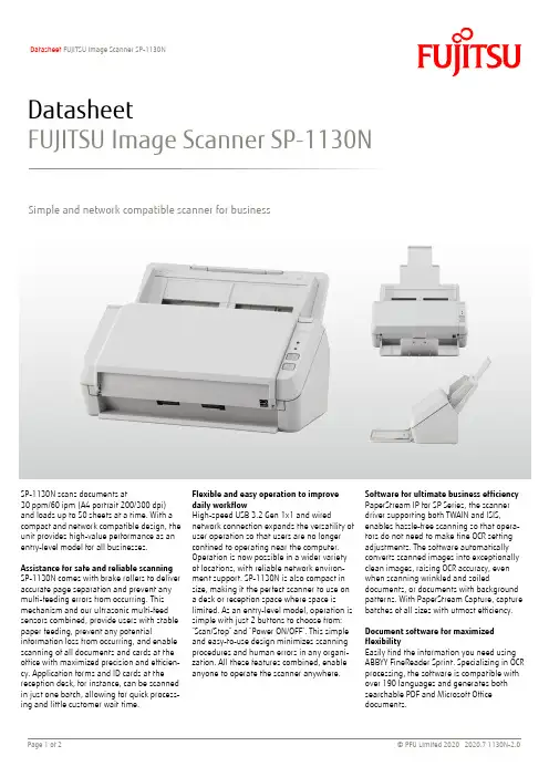
Software for ultimate business efficiency PaperStream IP for SP Series, the scanner driver supporting both TWAIN and ISIS, enables hassle-free scanning so that opera-tors do not need to make fine OCR setting adjustments. The software automatically converts scanned images into exceptionally clean images, raising OCR accuracy, even when scanning wrinkled and soileddocuments, or documents with background patterns. With PaperStream Capture, capture batches of all sizes with utmost efficiency. Document software for maximized flexibilityEasily find the information you need using ABBYY FineReader Sprint. Specializing in OCR processing, the software is compatible with over 190 languages and generates both searchable PDF and Microsoft Office documents.Flexible and easy operation to improve daily workflowHigh-speed USB 3.2 Gen 1x1 and wirednetwork connection expands the versatility of user operation so that users are no longer confined to operating near the computer. Operation is now possible in a wider variety of locations, with reliable network environ-ment support. SP-1130N is also compact in size, making it the perfect scanner to use on a desk or reception space where space is limited. As an entry-level model, operation is simple with just 2 buttons to choose from: “Scan/Stop” and “Power ON/OFF”. This simple and easy-to-use design minimizes scanning procedures and human errors in any organi-zation. All these features combined, enable anyone to operate the scanner anywhere.SP-1130N scans documents at30 ppm/60 ipm (A4 portrait 200/300 dpi) and loads up to 50 sheets at a time. With a compact and network compatible design, the unit provides high-value performance as an entry-level model for all businesses.Assistance for safe and reliable scanning SP-1130N comes with brake rollers to deliver accurate page separation and prevent any multi-feeding errors from occurring. This mechanism and our ultrasonic multi-feed sensors combined, provide users with stable paper feeding, prevent any potentialinformation loss from occurring, and enable scanning of all documents and cards at the office with maximized precision and efficien-cy. Application forms and ID cards at the reception desk, for instance, can be scanned in just one batch, allowing for quick process-ing and little customer wait time.Simple and network compatible scanner for businessDatasheetFUJITSU Image Scanner SP-1130NDatasheet FUJITSU Image Scanner SP-1130NTrademarksABBYY™ FineReader™ Engine © ABBYY. OCR by ABBYY. ABBYY and FineReader are trademarks of ABBYY Software, Ltd. which may be registered in some jurisdictions. ISIS is a trademark of Open Text. Microsoft, Windows, and Windows Server are either registered trademarks or trademarks of Microsoft Corporation in the United States and/or other countries. Any other products or company names appearing in this document are the trademarks or registered trademarks of the respective companies.Safety PrecautionsBe sure to carefully read all safety precautions prior to using this product and use this device as instructed. Do not place this device in wet, moist, steamy, dusty or oily areas. Using this product under such conditions may result in electrical shock, fire or damage to this product. Be sure to limit the use of this product to listed power ratings.ENERGY STAR®PFU Limited, a Fujitsu company, has determined that this product meets the ENERGY STAR® guidelines for energy efficiency. ENERGY STAR® is a registered trademark of the United States.Specifications are subject to change without notice. Visit the fi / SP Series website for more information. /*1 Actual scanning speeds are affected by data transmission and software processing times. *2 Indicated speeds are from using JPEG compression. *3 Indicated speeds are from using TIFF CCITT Group 4 compression. *4 Selectable maximum density may vary depending on the length of the scanned document. *5 Limitations may apply to the size of documents that can be scanned, depending on system environment, when scanning at high resolution (over 600 dpi). *6 Capable of scanning documents with dimensions exceeding that of Legal sizes. Resolutions are limited to 300 dpi or less when scanning documents 355.6 mm (14 in.) to 863 mm (34 in.), 200 dpi or less when scanning documents 863mm (34 in.) in length. *7 Thicknesses of up to 127 to 209 g/m² (34 to 56 lb) can be scanned for A8 (52 x 74 mm / 2.1 x 2.9 in.) sizes. *8 ISO7810 ID-1 type compliant. Capable of scanning embossed cards with total thicknesses of 1.24 mm (0.049 in.) or less. *9 Maximum capacity depends on paper weight and may vary. *10 Capable of setting additional documents while scanning.*11 Numbers are calculated using scanning speeds and typical hours of scanner use, and are not meant to guarantee daily volume or unit durability. *12 Scanning speeds slow down when using USB 1.1.*13 When using USB, device must be connected to the USB hub connected to the PC port. If using USB 3.2 Gen 1x1 (USB 3.0) / USB 2.0, USB port and hub compatibility is required. *14 Excludes the ADF paper chute and stacker. *15 Functions equivalent to those offered by PaperStream IP may not be available with the WIA Driver. *16 Refer to the SP Series Support Site for software downloads.Datasheet FUJITSU Image Scanner SP-1130NEvery 100,000 sheets or one yearBrake Roller Pick RollerPA03708-0001Roller SetConsumablesPA43404-A665 PaperStream Capture Pro optional license PaperStream Capture Pro Scan Station (WG)OptionsAC adapter, USB cable, Setup DVD-ROMIncluded Items Multi image output, Automatic color detection, Automatic page size detection, Blank page detection, Dynamicthreshold (iDTC), Advanced DTC, SDTC, Error diffusion, Dither, De-Screen, Emphasis, Dropout color (None/Red/Green/Blue/White/Saturation/Custom), sRGB output, Split image, De-Skew, Edge filler, Vertical streaks reduction, Digitalendorser, Background pattern removal, Character thickness, Character augmentation, Character extractionImage Processing FunctionsPaperStream IP for SP Series (TWAIN/TWAIN x64/ISIS), WIA Driver *¹⁵, PaperStream Capture, Software Operation Panel, Error Recovery Guide, ABBYY FineReader for ScanSnap *¹⁶, Scanner Central Admin, ABBYY™ FineReader Sprint™, Network Setup Tool for SP Series, SP Series Online UpdateIncluded Software / DriversWindows® 10, Windows® 8.1, Windows® 7, Windows Server® 2019, Windows Server® 2016, Windows Server® 2012 R2, Windows Server® 2012, Windows Server® 2008 R2Supported Operating System2.5 kg (5.5 lb)Weight298 x 135 x 133 mm (11.7 x 5.3 x 5.2 in.)Dimensions *¹⁴(Width x Depth x Height)ENERGY STAR®, RoHSEnvironmental Compliance 20 to 80% (non-condensing)Relative Humidity 5 to 35 °C (41 to 95 °F)Temperature Operating Environment 0.3 W or lessAuto Standby (Off) Mode2 W or less Power Saving Mode 18 W or less Operating Mode Power Consumption AC 100 to 240 V ±10 %Power Requirements 10BASE-T,100BASE-TX,1000BASE-T EthernetUSB 3.2 Gen 1x1 / USB 2.0 / USB 1.1USB *¹²*¹³Interface Overlap detection (Ultrasonic sensor)Multifeed Detection 4,500 sheetsExpected Daily Volume *¹¹50 sheets (A4 80 g/m² or Letter 20 lb)ADF Capacity *⁹*¹⁰50 to 209 g/m² (13.4 to 56 lb)*⁷Plastic Card 0.76 mm (0.0299 in.) or less *⁸Paper Paper Weight (Thickness)3,048 mm (120 in.)Long Page Scanning *⁶ (Maximum)52 x 74 mm (2.0 x 2.9 in.)Minimum216 x 355.6 mm (8.5 x 14 in.)Maximum Document Size WhiteBackground Colors Color: 24-bit, Grayscale: 8-bit, Monochrome: 1-bit Output Format 50 to 600 dpi (adjustable by 1 dpi increments)1,200 dpi (driver)*⁵Output Resolution *⁴(Color / Grayscale / Monochrome)600 dpiOptical ResolutionRGB LED x 2 (front x 1, back x 1)Light Source Single line CMOS-CIS x 2 (front x 1, back x 1)Image Sensor Type Simplex: 30 ppm (200/300 dpi)Duplex: 60 ipm (200/300 dpi)Scanning Speed *¹ (A4 Portrait)(Color *²/Grayscale *²/Monochrome *³)ADF (Automatic Document Feeder), DuplexScanner TypeTechnical InformationContactIndonesiaPT Fujitsu Indonesia Tel: +62 21 570 9330 *********************.com/id/scannersMalaysiaFujitsu (Malaysia) Sdn Bhd Tel: +603 8230 4188*********************.com/my/scannersPhilippinesFujitsu Philippines, Inc. Tel: +63 2 841 8488 ***************.com/ph/scannersSingaporeFujitsu Asia Pte Ltd Tel: +65 6512 7555******************.com/sg/scannersThailandFujitsu (Thailand) Co., Ltd. Tel: +66 2 302 1500 ***************.com/th/en/scannersVietnamFujitsu Vietnam Limited Tel: + 84 4 2220 3113 ****************.com/vn/en/scanners。
IntroductionThank you for purchasing the FUJIFILM Luminescent Image Ana-lyzer LAS-3000.This guide is used for explanation of the equipment. Therefore,this guide simply describes each function and usage. Please seethe Operation Manual for more detailed informations.Index1Features of the Luminescent Image Analyzer32System Configuration and Parts Identification33Preparation for Exposure61Activation62Setting of Samples64Exposure of Samples (Lite mode)71Setting of Mode72Method and Tray position Setting73Adjustment of Focus84Exposure Type and Exposure Time Setting85Setting of Sensitivity86Exposure97Saving the Exposed Image98Printing the Exposed Image109Termination105Exposure of Samples (Pro mode)116Cautions on Use121Sample Tray12Appendix12■Exposure Type12■Operation required to be carried out for exposure withgreen and red LED incident light sources (Optional)13■Detection Sensitivity and Number of Pixels14■Detection Reagents and Settings of LAS-300014∗In LAS-3000, the excitation light (incident/transmitted light), filter, lens, and the components of theanalytic part vary depending on the system you are using. Please confirm each system. The basicsystem of “LAS-3000” is described in this Operation Guide.23LAS-3000 OPERATION GUIDEIn LAS-3000, chemiluminescent and fluorescent samples can be detected in high sensitivity, Dark frame correction and Flat frame correction are equipped for the quantitative analysis of the images. A digitized image of stained gel, membrane or film can be obtained by white light illumination.●A super CCD camera of 3,200,000 pixels is employed. A high-resolution image of 6,300,000 pixels is obtained by the special image processing procedure.●A newly designed lens of F0.85 with remote focus and remote iris is mounted.Chemiluminescence can be detected in high sensitivity through use of a four-step pixel binning function.●Fluorescence can be detected in high sensitivity using a UV transmitted illuminator and incident blue LED.●Wider range of fluorescent reagents can be detected by the use of green and red incident LEDs in addition to the blue one (Optional).●The operability is remarkably improved by the newly designed Image Reader software.2System Configuration and Parts Identification< System configuration of LAS-3000: An Example >< Internal view of intelligent dark box (IDX) >NameDescriptionCamera headCCD cooling function and image data output USB port Intelligent dark box (IDX)Dark box Lens unitF0.85/43mmIncident light sourceBlue LED (460nm) incident light sources White LED incident light sourcesGreen LED (520nm) incident light sources (Optional)Red LED (630nm) incident light sources (Optional)Transmitted light source312nm UV light source or White transmitted light source1Features of the Luminescent Image Analyzer123544FilterY515Di (filter for blue LED)605DF40 (EtBr detecting filter)510DF10 (GFP detecting filter)575DF20 (filter for green LED) (Optional)R670 (filter for red LED) (Optional)Sample trayEPI tray (for chemiluminescence and incident light source)DIA tray (for transmitted light source)NP tray (for titer plate)DIA-UV tray (for UV transmitted light source)Computer Exposure operation and analysis work ●PictrographyHigh quality digital color printer6785LAS-3000 OPERATION GUIDEImage Reader SoftwareThe Image reader software consists of Lite and Pro modes. In the Lite mode, luminescence can be easily detected because a detection method has been set. In the Pro mode, advanced combination can be set.Method/Tray positionSets the detection method and tray position.FocusingAdjusts the focusing.StartStarts the exposure.MenuDarkbox option settingSets the light source, filter, and tray position.Lite mode selector buttonPress this button to switch to the Lite mode.FocusingAdjusts the focusing.StartStarts the exposure.Please use the Pro mode, in case of using green LED or red LED incident light source. Please use the Litemode for imaging of chemiluminescence, digitizing, EtBr detection by UV light source, fluorescence detec-tion by blue LED, using the preset conditions.63Preparation for Exposure1Activation2Setting of Samples32Turn ON the power switches of IDX, computer and peripheral equipments.StepOperation1Confirm that the temperature setting state of the CCD is ready.< Not Ready state >< Ready state >Open the IDX door and set the tray.Set the EPI tray and the DIA tray with the holed side placed toward you.Position 1Position 2Position 3Position 4Start up reading software LAS-3000 ImageReader.➟A message is displayed until the LAS-3000 is prepared.7LAS-3000 OPERATION GUIDE4Exposure of Samples (Lite mode)∗See Page 14 of this Operation Guide.1Setting of Mode1Confirm that the state is in the Lite mode.StepOperation42(2)Select Tray Position according to the sampleused.(3)Click the OK button.The light source and filter are set by the pre-determined combination.2Method and Tray position SettingSelect the Method.DetectionMethodChemiluminescence and Chemiluminescence bioluminescenceFluorescence using the UV light Fluorescence:EtBrsource (of 312 nm)Fluorescence using blue LED Fluorescence:SYBRGreen,GFP l incident light source (of 460 nm)Digitization using white Digitize:EPI incident light source Digitization using white Digitize:DIAtransmitted light source∗Please use the Lite mode for imaging of chemiluminescence, digitizing, EtBr detection by UV lightsource, fluorescence detection by blue LED, using the preset conditions. Please use the Pro mode,in case of using green LED or red LED incident light source. (See Page 11 of this Operation Guide)8Select Precision for Exposure Type.Check Auto or Manual for Exposure Time.< For setting of Auto >< For setting of Manual >3Adjustment of FocusConfirm the sample position and focus.Click the Return button.The brightness of view-ing becomes dark.Adjusts the focus. Click these buttons to perform coarse adjustment.Performs precise focus adjustment.The sensitivity is improved by binning mul-tiple pixels into one big pixel. Smoothing bythe interpolation of pixels causes the num-bers of pixels to increase.The sensitivity becomes higher in the order of Standard, High, Super and Ultra.5Setting of SensitivitySensitivity Original pixels Standard High Super Ultra∗ See Page 14 of this Operation Guide.The brightness of view-ing becomes light.The adjustment of brightness does not influ-ence the actual exposure.4Exposure Type and Exposure Time Setting 45Automatic exposure is done after pre-expo-sure.∗ See Page 12 of this Operation Guide.Select an exposure time from the list or enter the exposure time using a numeric value.Only in the Chemiluminescence mode, Image acquire & Digitize function can be used. This function can expose chemiluminescence and digitize images consecutively at one click.9LAS-3000 OPERATION GUIDE6ExposureClick the Start button. Exposure is started.➟The orange Busy LED lights during exposure.77Saving the Exposed Image< Save function is also in the File menu >Set the folder for saving a file, the file name, and the file type then click the Save button.< For Windows ® >< For Macintosh TM >< File format >●Fuji Img/Inf formatThis is a file format developed exclusively by FUJIFILM.This format is suitable for the analysis in which the quantitative performance was maintained.●16 bit Linear TiffThis is 16-bit Tiff format.This format enables the analysis in other software.●8bit Color TiffThis is a Tiff format having eight-bit color gradation.The changed gradation can be saved as it is.The file name is automatically set,but it can also be changed.(Example)20021010_1300For FUJI Img/Inf format, you can enter a comment.Select the file for-mat.DateTime↑↑Save button10< Print function is also in the File menu >< For Windows ® >Select the output setting of a printer and the type (full-scale print or screen print) of a print to be output. Click the OK button.For the screen print, display the screen you wish to output.➟The image is printed.< For Macintosh TM >Select the type (full-scale print or screen print) of a print to be output. Click the OK button.For the screen print, display the screen you wish to output.Click the Print button.➟The image is printed.8Printing the Exposed Image42Select Quit from the File menu.Select whether to keep or stop the CCD cooling.Click the OK button.Terminate the personal computer.Turn OFF the IDX power switch.9TerminationStepOperation13Print buttonClick the Complete button.➟The current display returns to the initial screen.11LAS-3000 OPERATION GUIDE5Exposure of Samples (Pro mode)The desired light source and filters can be selected for exposure.Select the light source.Light:None (No light source provided)UV (312 nm transmitted light)Blue (460 nm incident light)Green (520 nm incident light) (Optional)Red (630 nm incident light) (Optional)EPI-White (White incident light)DIA-White (White transmitted light)Select the filter.Filter:1Through (No filter provided)2605DF40 (EtBr detection)3Y515Di (for blue LED) or 510DF10 (for GFP)4575DF20 (for green LED) (Optional)5R670 (for red LED) (Optional)∗The setting can be changed.Select the iris.Iris:F0.85 (For blue, green, red, white-EPI)F2.8 (For UV, white-DIA)(5)Click the Next button.Select the FlatFrame file made for the selected conditions.Click the OK button.(6)FlatFrame is a correction file required to cor-rect the characteristics of a lens. It can be created by FlatFrame Calibration in the Op-tion menu.∗Please use the Pro mode, in case of using green LED or red LED incident light source. Please usethe Lite mode for imaging of chemiluminescence, digitizing, EtBr detection by UV light source,fluorescence detection by blue LED, using the preset conditions.∗ *See Pages 133 and 134 of the Operation Manual.3See Page 8.3. Adjustment of Focus 3.4See Page 8.4. Exposure Type and Exposure Time Setting.See Page 8.4. Exposure Type and Exposure Time5.512■ Exposure TypePrecision .........Exposes for the entire time set in Exposure Time.Increment ........Exposes for each time set in Interval Time and accumulates the images.Repetition ........Exposes for each interval time set in Interval Time and displays images for each section.Program...........Exposure time and interval time can be set. Each image file and integrated image filescan be generated and saved.Appendix6Caution on Use1Sample Tray1.We recommend the use of a hybridization bag to prevent the membrane from being dried. In such a case, fix the portion, not covered with the membrane, to the tray using a seal so as to keep the membrane flat.A sharp image can be obtained.2.Wash the sample tray with water and dry it suf-ficiently before use when it is unclean.In the Pro mode, the detection of a binning image (High binning, Super binning, and Ul-tra binning) and High resolution image can also be selected in addition to Standard, High,Super, and Ultra. See Page 13 of this Opera-tion Guide for the relationship between the sensitivity and the number of pixels.See Page 9.6. Exposure 7.713LAS-3000 OPERATION GUIDE(2) Installing the incident light source2. Installing the optional filter.Select Filter Customization from Option menu with the IDX door closed.Click "Filter down" button.Open the IDX door after the filter changer has come down.Enter the name of the option filter in the box and press the OK button.■ Operation required to be carried out for exposure with green and red LED incident light sources (Optional)1. Changing the LED incident light sourcesThis operation should be carried out with Tray placed in position 4.The same procedure should be carried out respectively for the right and left sides.(1) Removing the incident light source ∗ See Page 7 of this Operation Guide 2 (2).123514■ Detection Reagents and Settings of LAS-3000■ Detection Sensitivity and Number of PixelsSensitivity Number of pixels (W ✕ H)Image file size High Resolution 3072 ✕ 204812.6 MB Standard 1536 ✕ 1024 3.15 MB High 1536 ✕ 1024 3.15 MB Super 1536 ✕ 1024 3.15 MB Ultra 1536 ✕ 1024 3.15 MB High Binning 768 ✕ 512786 KB Super Binning 384 ✕ 256197 KB Ultra Binning 192 ✕ 12849.2 KBSetting of LAS-3000ClassificationReagent name Lite mode Pro modeMethodLight Filter IrisECLChemiluminescence none Through 0.85ECL PlusChemiluminescence none Through 0.85Lumi-Light Plus Chemiluminescence none Through 0.85ChemiluminescenceRenaissance Chemiluminescence none Through 0.85Super Signal ®Chemiluminescence none Through 0.85Bright-Star Chemiluminescence none Through 0.85CDP-Star Chemiluminescence none Through 0.85CSPDChemiluminescencenone Through0.8515LAS-3000 OPERATION GUIDESetting of LAS-3000Classification Reagent name Lite mode Pro mode Method Light FilterIris SYBR ® Green I Fluorescence:SYBR Green Blue(460nmEPI)Y515-Di 0.85SYBR ® Green II Fluorescence:SYBR Green Blue(460nmEPI)Y515-Di 0.85IntercalateSYBR ® Gold Fluorescence:SYBR Green Blue(460nmEPI)Y515-Di 0.85EtBr Fluorescence:EtBr UV(312nmDIA)605DF402.8TOTO-3-Red(630nmEPI)R6700.85SYPRO ® Ruby Fluorescence:SYBR Green Blue(460nmEPI)Y515-Di 0.85SYPRO ® Orange Fluorescence:SYBR Green Blue(460nmEPI)Y515-Di 0.85Protein SYPRO ® tangerine Fluorescence:SYBR Green Blue(460nmEPI)Y515-Di0.85stainDeep Purple -Green(520nmEPI)605DF400.85SYPRO ® Red -Green(520nmEPI)605DF400.85Pro-Q Diamond -Green(520nmEPI)575DF200.85FITC Fluorescence:SYBR Green Blue(460nmEPI)Y515-Di 0.85FAM TMFluorescence:SYBR Green Blue(460nmEPI)Y515-Di 0.85Alexa ® 488Fluorescence:SYBR Green Blue(460nmEPI)Y515-Di 0.85Cy2TM Fluorescence:SYBR Green Blue(460nmEPI)Y515-Di0.85Cy3TM -Green(520nmEPI)575DF200.85HEX TM -Green(520nmEPI)575DF200.85NED-Green(520nmEPI)605DF400.85FluorescenceTetramethylrhodamine -Green(520nmEPI)575DF200.85dyeR-phycoerythrin -Green(520nmEPI)575DF200.85LabelingT AMRA TM-Green(520nmEPI)575DF200.85BODIPY 576/589-Green(520nmEPI)605DF400.85Rhodamine Red -Green(520nmEPI)605DF400.855-ROX TM-Green(520nmEPI)605DF400.85Alexa ® 514 532 546 555-Green(520nmEPI)575DF200.85Alexa ® 568 594-Green(520nmEPI)605DF400.85DiD-Red(630nmEPI)R6700.85BODIPY -Red(630nmEPI)R6700.85Cy5TM-Red(630nmEPI)R6700.85Alexa ® 633 635 647-Red(630nmEPI)R6700.85Alexa ® 660 680Fluorescent EGFP Fluorescence:GFP Blue(460nmEPI)510DF100.85proteinECFP Fluorescence:GFPBlue(460nmEPI)510DF100.85RFP-Green(520nmEPI)605DF400.85Attophos ∗1Fluorescence:SYBR Green Blue(460nmEPI)Y515-Di 0.85Chemifluo-ECL Plus Fluorescence:SYBR GreenBlue(460nmEPI)Y515-Di 0.85rescenceHNPP-Green(520nmEPI)575DF200.85DDAO phosphate ®-Blue(460nmEPI)R6700.85Silver stain Digitize:DIA White(DIA)Through 2.8DigitizeCBB stain Digitize:DIA White(DIA)Through 2.8X-ray film Digitize:DIA White(DIA)Through 2.8NBT/BCIPDigitize:DIAWhite(DIA)Through2.8∗1: Attophos cannot be used for detecting the nucleic acid on Nylon membrane.Note) The pre-label method detection by UV illumination is not licensed.Support services of LAS-3000 is provided by your local supplier.LIFE SCIENCE, INFORMA TION PRODUCTS MARKETING DIV.FUJI PHOTO FILM CO.,LTD.PHONE:+81-3-3406-2201FAX:+81-3-3406-2158e-mail:*********************.co.jpURL:/products/science/index.html。

IMPORTANT SAFETY INSTRUCTIONS:Please read user guide before using this product.Please keep user guide for future reference.Please read the cautions to prevent possible danger and loss of property.FEATURES:High resolution: 1920×1200;Wide voltage: DC 7-24V;High brightness: 500cd/㎡;High contrast: 1000:1;CAUTIONS:1. Please do not place the display screen towards the ground.2. Please avoid heavy impact or drop onto the ground.3. Please do not use chemical solutions to clean this product. Please wipewith a clean soft cloth to maintain the brightness of the surface.4.Please do not block any vent hole.5. Please follow the instructions and trouble-shootings to adjust theproduct. Other improper adjustment may result in damage. Any furtheradjustment must be performed or conducted by a qualified technician.6.Please unplug the power and remove the battery if long-term no-use,1or thunder weather.YP-01180328-1Contents1. PRODUCT DESCRIPTION (4)2. DV BATTERY MOUNT PLATE (5)3. MENU SETTING (6)4. ACCESSORIES (9)5. PARAMETERS (11)6. TROUBLE SHOOTING (11)2Confirm function: press to confirm after option selected.3.EXIT4.F1、F2、User-definable buttons.Default functions: (function customized to meet your needs)F1 Peaking F2 Level Meter5.INPUT: circularly switch among of SDI and HDMI.6. Cooling holes7.Speaker8.SDI input interface.9.SDI output interface.10.Earphone jack.11.USB input(Only for program upgrades, do NOT use if non-professionals) 12.HDMI output interface.13.HDMI input interface.14.DC 12V power input.2. DV BATTERY MOUNT PLATEStandard mounts process5DV Battery Mount Plate Specification:F970 for battery of SONY DV: DCR-TRV series, DCR-TRV E series, VX2100E PD P series, GV-A700, GV-D800 FD/CCD-SC/TR3/FX1E/HVR-AIC, HDR-FX1000E, HVR-Z1C, HVR-V1C, FX7E F330.3. MENU SETTINGBefore setting the functions, please make sure the device is connected correctly.3-1. F1~F2 User-definable function buttons:Select "MEMU -- SYSTEM -- F1 Configuration/F2 Configuration" to custom F1 / F2 shortcut settings. Then left or right sliding the dial to choose options.Select option via sliding to the left or right.Press to confirm option as default, then press EXIT to exit.Functions of F1-F2 buttons can also be customized: Center Marker, Aspect Marker, Check Filed, Underscan, Scan, Aspect, DSLR, Freeze, Peaking, False Color, Exposure, Histogram, Level Meter.F1-F2:2 user-definable function buttonsDefault function:F1:Peaking F2:Level Meter69 4. ACCESSORIESStandard:Peaking Color Red, Green, Blue, White, Black Peaking Level 0~100 False Color OFF, ON Exposure OFF, ON Exposure Level 0~100 Histogram OFF, ON Audio Volume0~100SDI Audio Channel Ch0&Ch1, Ch2&Ch3, Ch4&Ch5, Ch6&Ch7,Ch8&Ch9, ChH10&Ch11, Ch12&Ch13,Ch14&Ch15(available under SDI mode only.)Level Meter OFF, ON System Language English, Chinese OSD Timer 10s, 20s, 30s Image FlipOFF, H, V, H/V Back Light0~100F1 Configuration Peaking F2 Configuration Level Meter ResetPress to confirm after selected.1. 12V DC adapter 1 piece2. HDMI A/C cable 1 piece3. Shoe mount 1 piece4. Folding sun shade cover 1 piece5. VESA battery plate 1 piece6. Manual 1 copy10115. PARAMETERS6. TROUBLE SHOOTING1. Only black-and-white display:Check whether the color saturation is properly setup or not. 2. Power on but no pictures:Check whether the cables of HDMI are correctly connected or not. PleasePanel7” IPSPhysical Resolution1920×1200 (324ppi) Brightness 500 cd/㎡ Contrast 1000: 1 Viewing Angle 170°/ 170°(H/V) Input Voltage DC 7-24VInput Signal HDMI, SDI Output Signal HDMI, SDI4K HDMI 4096×2160 24p / 3840×2160 (23/24/25/29/30p) Power Consumption ≤12W Operating Temperature -20℃~60℃ Storage Temperature-30℃~70℃ Dimension (LWD)182×124×22mm Weight435guse the standard battery.3. Wrong or abnormal colors:Check whether the cables are correctly and properly connected or not.Broken or loose pins of the cables may cause a bad connection.4. When on the picture shows size error:Press “MENU →FUNCTION →Underscan” to zoom in/out pictures automatically when receiving HDMI signals5. Other problems:Please press dial button and choose “MENU→SYSTEM→ Reset →ON”Note: due to constant effort to improve products and product features, specifications may change without notice.12。
Broadening the possibilities of video expression 1920 x 1080 True HD 3CCD cameraPanasonic ,s 3CCD camera with true 16 x 9 multi format high definition delivers sharp, pure color images. The camera is an ideal solution for microscopy, industrial endoscopy, special effects, and many other applications.Conventional imageGP-US932 imageT r u e m u l t i -f o r m a t H D I n a d d i t i o n t o t h e 1080i (1920 x 1080) t r u e H D m o d e , 720p (1280 x 720), 480p a n d 480i (720x 480) m o d e s a r e se l e c t a b l ef o r s h ar p , h i g h r e s o l u t i o n f l i c k e r -f r e e i m a g e s .*The images are samples.E x p a n d e d d y n a m i c r a n g e D e t a i l i n t h e b r i g h t a r e a s a n d c o n t r as ti n t h e d a r k a r e a s a r e r e p r o d u c e da s a w e l l -b a l a nc ed i m a ge .(T h e t w o i m a ge s t o t he r i g h ta r e a c tua l p i c t u r e s u s i n gt he e x p a n d e d d y n a mi c r a n g e fu n c t i o n.)T r u e -t o -l i f e c o l o r s T w e l v e i n d e p e nd e n t l y a d j u s t a b l e a x i s I n p a r t i c u l a r , t h ee x c el l e n t r e d -c o l o rr e p r o d u c i b i l i t yi s s u i t e d f o r b i o l o g i c a l a n d m ed i ca l a p p l i c a t i o n s .*Recommended lenses are optionally available.The new 1/3-type progressive CCD features exceptionally high sensitivity with a large light-receiving area for each pixel. Balanced high resolution and S/N ratio is achieved from the combination of high-performance image processing technology implemented by a new digital signal processor (DSP).New high-sensitivity progressive CCDProgressive capture is followed by 14-bit A/D conversion and newly developed DSP for 19-bit internal processing. The result is extraordinary high-precision 1920 x 1080 true HD image output.Newly developed DSP with 14-bit A/D conversionand 19-bit processing functionsHigh-sensitivity 3CCDFujinon* HD lensFujinon* SD lensSpecifications of Recommend LensesRecommend LensesHAF4.8DA-1XA4x7.5DA-1TF2.8DA-8TF4DA-8TF8DA-8TF15DA-8Model No.Manufacturer Focal Length (mm)Zoom RatioMaximum Aperture RatioAngle of View (˚)HorizontalVerticalMinimum Object Distance (m / ft)Filter Thread Mount FocusIrisLength (from focal plane)(mm / inch)Full Aperture (mm / inch)Weight (g / lbs)HAF4.8DA-1Fujinon*4.8 2.2 57.07˚34.05˚0.1 / 0.33M55C Manual Manual 53.126 / 2.092(in air)ø42 / ø1.65495 / 0.21XA4x7.5DA-1Fujinon*7.5 – 304 2.8 38.38˚ – 9.94˚22.18˚ – 5.61˚0.45 / 1.48M52C Manual Manual 178.926 / 7.044(in air)ø54 / ø2.126500 / 1.1TF2.8DA-8 Fujinon*2.8 2.2 85.98˚55.40˚0.1 / 0.33 N/A C Manual Manual 64.025 / 2.521(in air)ø34 / ø1.33975 / 0.17TF4DA-8 Fujinon*4 2.2 66.25˚40.36˚0.1 / 0.33 M27 x 0.5C Manual Manual 63.025 / 2.481(in air)ø29 / ø1.14270 / 0.15TF8DA-8 Fujinon*8 2.2 36.14˚20.82˚0.1 / 0.33M25.5 x 0.5C Manual Manual 56.526 / 2.225(in air)ø29 / ø1.14260 / 0.13TF15DA-8 Fujinon*15 2.2 19.74˚11.19˚0.1 / 0.33M25.5 x 0.5C Manual Manual 56.526 / 2.225(in air)ø29 / ø1.14260 / 0.13HD LensesSD Lenses* Fujinon Lenses: Please contact to your distributorPanasonic technology enables high definition image quality covering a wide range of applicationsThe lineup includes HDMI output and HD-SDI/SD-SDI output models for different applications and purposes.HDMI output model lineupHDMI, HDMI logo, and High-Definition Multimedia Interface are trademarks orregistered trademarks of HDMI Licensing LLC.Beautiful, true-to-life colors are reproduced. Each of the 12 axis can be independently adjusted without affecting the adjacent color vector. The excellent red-color reproduction is ideal for biological and medical applications.Excellent color performanceA higher-level vertical resolution is obtained from P/I conversion, line conversion, and down conversion of native images with high vertical resolution from full-frame 59.94 fps progressive scanning. High image quality unparalleled by electronically interpolated interlace scanning is obtained.High-resolution native progressive scanConventional imageGP-US932 image*The images are samples.Simply select the appropriate functions from the list of camera functions displayed on the monitor screen to complete the setting.Images can be adjusted easily and efficiently while observing the images.Easy set-up menuThe functions provide high-precision true HD outputs.14-bit A/D conversion and 19-bit processing DSPThe new proprietary expanded dynamic range function expands the contrast of the dark areas while maintaining detail in the bright areas. Objects with high contrast can be represented as natural images.Proprietary expanded dynamic range functionConventional imageExpanded dynamic range image*Actual camera images<Parameters>Each of the three independent scene files has twelve parameters that can be customized to suit any applications.Three scene filesDetail Red detail Gamma KneeBlack stretch Dynamic range White clipFlare compensationDigital noise reduction Color matrix Chroma gain Total pedestalElectronic zoom up to 2.5xFreeze function White balanceElectronic shutter Gain control Electronic zoom up to 2.5x allows checking finer detail.Motionless video images can be displayed while capturing video.ATW (auto-tracking white balance) mode,AWC (automatic white balance) mode, or manual white balancemode can be selected according to the illumination of the scene.ELC mode (automatic shutter speed control accordingto the object`s amount of light), STEP mode (selection from 1/100, 1/250, 1/500, 1/1000, 1/2000, 1/4000, or 1/10000 to obtain the optimal setting), or select MANU mode.AUTO (automatic gain control) will provide automatic adjustment of sensitivity. Manual adjustment of sensitivity is also available.Other features。
声光超分辨率成像原理Super-resolution imaging is a technique that enhances the resolution of an image beyond the typical limit of a sensor or optical system. In the case of super-resolution acoustic imaging, the technique involves using multiple microphones to capture sound waves from different angles and distances in order to reconstruct a higher resolution image of the source of the sound.超分辨率成像是一种技术,它可以提高图像的分辨率,超越传感器或光学系统的典型极限。
在超分辨率声学成像的情况下,该技术涉及使用多个麦克风从不同角度和距离捕捉声波,以重构声源的更高分辨率图像。
The principle of super-resolution imaging involves taking multiple low-resolution images of a scene or object and then using computational algorithms to combine and enhance the details to create a single, high-resolution image. This can be achieved through various techniques such as interpolation, deconvolution, and deep learning-based super-resolution.超分辨率成像的原理涉及拍摄场景或物体的多个低分辨率图像,然后使用计算算法将这些图像合并并增强细节,以创建一张高分辨率图像。
high definition 和high resolution 概述及解释说明1. 引言1.1 概述高清晰度(High Definition)和高分辨率(High Resolution)是在现代科技快速发展的背景下,广泛应用于各个领域的概念。
随着技术的进步,从电视、摄影到计算机显示器等,人们对图像质量和精细度要求越来越高。
高清晰度和高分辨率成为满足这一需求的重要技术指标。
本文旨在全面介绍和解释高清晰度和高分辨率的概念、发展历程、应用领域以及优势,并探讨它们之间的相似之处、区别,以及彼此之间的影响与补充关系。
最后,文章将总结其重要性,并展望未来对于这两个概念在技术发展中可能带来的变化。
1.2 文章结构本文将按照以下章节进行介绍:- 引言:对文章主题进行概述,并简要介绍文章内容和目的。
- 高清晰度(High Definition):定义和解释该概念,回顾其技术发展历程,并探讨其应用领域和优势。
- 高分辨率(High Resolution):给出对该概念的定义和解释,追溯其技术发展历程,并讨论其应用领域和优势。
- 对比与联系:比较高清晰度和高分辨率之间的相似之处和区别,探究它们彼此之间的影响与补充关系。
- 结论:总结高清晰度和高分辨率在各个领域中的重要性,并展望对技术发展可能带来的影响。
1.3 目的本文旨在提供关于高清晰度和高分辨率概念的全面解释和说明。
通过讨论它们的定义、技术发展历程、应用领域和优势,读者将能够更好地理解这两个概念及其在现代科技中的重要性。
同时,文章将进一步比较它们之间的相似之处与区别,探究彼此之间的影响与补充关系,并探讨未来可能出现的趋势。
通过具体实例和详细解释,读者将更加深入地了解这两个概念以及它们对于不同领域的实际应用意义。
2. 高清晰度(High Definition)2.1 定义和解释高清晰度(High Definition,简称HD)是指图像或视频中能够呈现出更多细节和更真实的色彩的特征。
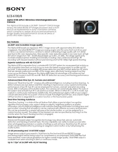
Key Features24.2MP 2 and incredible image qualityThe Alpha 6100 boasts an impressive APS-C image sensor with approximately 24.2 effective megapixels, the latest BIONZ X™ image processing engine and the same front end LSI as used on Sony’s acclaimed full-frame cameras to deliver outstanding image quality with rich detail and true-to-life color reproduction. Area specific noise reduction results in low noise even at high ISO which ranges from 100 – 32,000 (Expandable up to ISO – 51,200). The design significantly increases readout speed, enabling functionality including 11fps continuous shooting 5, 4K recording 3 with full pixel readout without pixel binning and Full HD 120fps high-speed shooting.Superior autofocus with 4D FOCUS™The Alpha 6100 incorporates Sony’s unrivaled 4D FOCUS™ system for unsurpassed fast autofocus (AF) acquisition time that can lock focus on even the fastest moving subject in as little as 0.02 seconds 1. It also boasts an incredible 425 phase detection and 425 contrast detection AF points that are densely positioned over 84% of the image area, effectively tracking subjects as they move across the frame. Moreover, the Alpha 6600 takes full advantage of its enhanced fast hybrid AF for movies in both HD and 4K 3. Both AF detection accuracy and tracking performance have been boosted.Advanced Real-time Eye AF, humans and animals 6Advanced “Real-time Eye AF 6” employs (Ai) artificial intelligence, including machine learning , to detect and process eye data in real time, resulting in improved accuracy, speed and tracking performance of Eye AF. Eye AF can be employed for humans, animals 6 and when recording movie. With a half press of the shutter button, the camera can automatically detect the eyes of the subject and activate Eye AF in all autofocus modes. When in either AF-C or AF-A mode, eye capture is continuously maintained. Additionally, the preferred eye (right or left) of your subject can be selected as the focus point. Choices include Auto/Right Eye/Left Eye, and a Switch Right/Left Eye function is assignable to a custom function or the touchscreen panel.Real-time Tracking Autofocus“Real-time Tracking” is a state-of-the-art feature that utilizes a special object recognition algorithm that processes color, subject distance (depth), brightness (pattern) as spatial information, plus AI (Artificial Intelligence with machine learning) information including face and eye location, ensuring that all subjects can be captured with extreme accuracy and precision. This can be activated by a simple half press of the shutter button, or can be assigned to a custom function as well. The subject to be tracked can also be specified by touching it on the monitor when the Touch Tracking function is engaged.Real-time Eye AF for animals 6Advanced AI-based subject recognition technology now allows fast, precise, automatic detection and tracking of animal 6 eyes. This new capability can vastly increase success rates when photographing animals in a variety of settings or pets at home. Real-time Eye AF animal mode can be initiated either by pressing an assigned custom button or by half-pressing the shutter button.16-bit processing and 14-bit RAW outputImage sensor output is processed in 16-bit form by the front-end LSI and BIONZ X image processing engine before being output as compressed or uncompressed 14-bit RAW files that have smoother, more natural gradations for higher overall image quality. 14-bit RAW output is available even when shooting in silent or continuous mode.Up to 11fps 5 at 24.2MP with AE/AF trackingILCE-6100/BAlpha 6100 APS-C Mirrorless Interchangeable-LensCameraThe Alpha 6100 include a 24.2MP 2 Exmor™ CMOS image sensor, the latest BIONZ X™ image processor and a front-end LSI as implemented in Sony’s full-frame cameras, which combine to deliver all-round enhancements in image quality and performance across all areas of photo and video capture.The Alpha 6100 has been designed to allow for high resolution, continuous shooting at high frame rates. It features a front-end LSI that works with the image sensor, BIONZ X image processing engine and a newly designed shutter mechanism with ‘braking feature’ to enable continuous shooting at impressive speeds up to 11fps5 with continuous autofocus and auto-exposure tracking at full 24.2MP resolution while utilizing the mechanical shutter, and up to 8 fps5 with full AF/AE tracking while silent shooting.4K movie3 w/ full pixel readout, no pixel binningThe Alpha 6100 offers internal 4K (QFHD: 3840 x 2160) recording3 in Super 35mm format with full pixel readout and no pixel binning at 2.4x oversampling4 (6K equivalent) for the ultimate 4K footage with exceptional detail and depth. Additional the Alpha 6100 has the ability to record Full HD at 120 fps for up to 5x slow motion HD video7 and a mic jack with XLR compatibility via the MI shoe, focus peaking, clean HDMI output and much more.Touch Tracking for moviesTouch Tracking is beneficial for movie recording. Touch the subject to be tracked on the monitor, and the Real-time Tracking function will then process color, pattern (brightness), distance (depth), and face information to precisely and smoothly track the selected subject at the specified sensitivity and speed. It is also possible to half-press the shutter button or press the AF ON button while shooting to achieve fast focus (AF-S). This can be an advantage for weddingsor documentaries, where there is only one chance to capture a scene. In such cases the focus area selected in advance is applied.180-degree tiltable LCD touch screen for self-recordingThe fully tiltable (180-degree), 3” (3.0-type) LCD flip screen with 921k-dots of high-resolution allows for simple and effective selfie-style shooting for both still image and video capture. Utilizing this capability, vloggers will be able to check and monitor composition throughout their entire creative process. The LCD screen is also equipped with touch functionality, with options for Touch Pad, Touch Focus, Touch Shutter and new Touch Tracking which quickly activates “Real-time Tracking” through the touch screen.Wi-Fi®/NFC™/QR code for easy file transfer and remote control8Easily connect with NFC or QR code (for non-NFC devices) to smartphones or tablets with the built-in Wi-Fi® and Sony’s PlayMemories Mobile™ application available for free on the Android™ and iOS platforms8. Control your camera or transfer files to your device for fast and easy sharing without the need of a computer. It also supports Sony’s growing range of PlayMemories Camera Apps™, which add a variety of creative capabilities to the camera. Then when you’re done, you can use the free software to sort and manage your stills and video with PlayMemories Home™ or edit your RAW file with either Sony’s Image Data Converter or Capture One Express (for Sony). Make it your own with easy button and dial customizationMake operation more intuitive, quick and easy. You can assign any of 89 functions to any of 8 custom buttons. Independent function sets can be assigned for stills, movies, and playback. “My Dial” allows for frequently-used functions to be assigned to the control dial and control wheel. The My Menu function allows up to 30 frequently-used menu items to be registered. They can be re-ordered by frequency of use, and little-used items can be deleted, allowing the user to create a menu that reflects their usage patterns.Interval Recording7 for time-lapseInterval shooting7 (continuous shooting with a set interval) is possible to create time-lapse movies, without requiring an app or external interferometer. Shooting interval can be set to anywhere between 1 second and 60 seconds, and the number of shots to anywhere from 1 to 9999. AE tracking sensitivity can be set to ”High”, “Mid” or “Low” during interval shooting to control your exposure and silent shooting can be activated to reduce shutter vibration. To extend shooting periods, a mobile battery can be used while the internal battery remains in the camera. Still images shot can be edited into a time-lapse movie on a computer with the latest version of Imaging Edge software (Remote/Viewer/Edit) and PlayMemories Home.Slow and quick motion7Slow and quick motion7 offers an almost endless variety of creative ways to express the passage of time. Frame rates from 1 fps to 120fps (100fps) can be selected in eight steps for full HD up to 50 Mbps; 60x quick motion/5x slow in NTSC and 50x quick motion/4x slow in PAL.4K movie transfer to smartphone8By using the newly introduced smartphone app Imaging Edge Mobile, high-bitrate movies including 4K can be transferred to smartphones (Probability of transfer / playback depends on the performance of the smartphone). Refer to the product information for Imaging Edge Mobile for detailsImaging Edge desktop applicationsTo support an efficient, high speed, connected professional workflow, Sony provides “Imaging Edge” desktop applications. Use "Remote" to control and monitor shooting live on your PC screen; "Viewer" to quickly preview, rate, and select photos from large image libraries; and "Edit" to develop RAW data into high-quality photos for delivery. Get the best from Sony RAW files, and manage your productions more efficiently. To maximize convenience in image transfer, when utilizing the latest version of Sony’s Imaging Edge Mobile™ application, the camera can now transfer images to a connected smartphone even if the camera’s power is set to OFF. Refer to the download page for details: /disoft/d/Specifications1. Based on Sony research, CIPA-guideline-compliant internal measurement with an E 18-135mm F3.5-5.6 OSS lens mounted, Pre-AF off and viewfinder in use.2. Approximately, effective megapixels3. 3840×2160 pixels. A Class 10 or higher SDHC/SDXC memory card is required to record movies in the XAVC S format. UHS-I (U3) SDHC/SDXC card is required for 100Mbps4. Standard ISO 100 up to ISO 32000 expandable to ISO 100 to ISO 51200for still images5. High-speed continuous shooting is available at up to approx. 11fps in “Hi+” continuous shooting mode and up to approx. 8fps in “Hi” continuous shooting mode. Maximum fps will depend on camera settings.6. Accurate focus may not be achieved with certain subjects in certain situations.. Real-time Eye AF for Animals supports still images only and cannot be used in combination with tracking. Does not work with some types of animal.7. Wi-Fi does not work during interval shooting8. Imaging Edge Mobile Ver. 7.2 or later is required© 2019 Sony Electronics Inc. All rights reserved. Reproduction in whole or in part without written permission is prohibited. Sony is not responsible for typographical and photographic errors. Features and specifications are subject to change without notice. Sony, G Master, the Alpha logo and the Sony logo are trademark of Sony Corporation. All other trademarks are trademarks of their respective owners.。
C H200H i g h-S p e e d S c a n n e rManualCONTENTSService information (2)Chapter I Introduction (3)1.1 Package contents (3)1.2 Appearance (3)1.3 Recommended configuration (3)1.4 Product functions, parameters and application (4)1.4.1 Functions (4)1.4.2 Parameters (5)1.4.3 Applications (5)Chapter II Installation (6)2.1 Structural drawing (6)2.2 Software CD (6)2.3 Driver Installation (7)2.4 Software Installation (13)Chapter III Software Interface Instruction (17)3.1 Application (17)3.2 Menu (18)3.2.1 File (18)3.2.2 Edit (20)3.2.3 View (21)3.2.4 Snapshot (22)3.2.5 Image (23)3.2.6 Effect (25)3.2.7 Tool (27)3.2.8 Help (28)3.3 Tool Information (28)Service informationNetwork servicesYou can get technique support and related information though our company website and telephone.After-sales insurance notes1、All the after-sales policy complies with the stipulation of "three packages".2、Maintenance service is non-freight, charge retails and overhauling programs by nextyear.3、When the products are sent to repaired, total package is demanded to ensure the qualityof maintenance.4、Non-warranty scope●The damage is made by irresistible disease such as natural disease.●Personal factors.●Improper use.●Problems and error made by other software of installation and design.●Computer virus.●One that tear original warranty serial number card or non-serial number card willcancel his rights of maintenance and not provide maintenance.5、If the adverse products are generated by factors of non-warranty scope, we'll chargeunder the standard required by company, which has nothing to do with warranty years.6、The warranty scope is only for the product itself without joint maintenance responsibilityfor supplies.7、During repairing, our company is not responsible for the interests of purchaser andpotential damage in foreseeing circumstances.Suggestion for useThe effect is better under the environment of adequate lighting.Chapter I Introduction1.1 Package contents(1)High-Speed Scanner(2)High-Speed Scanner Special manuscript desk(3)CD-ROM(including driver programs, operation instructions and application procedure)(4)Cable for USB 2.0(5)Instruction for user(6)YardstickIf above package accessories are incomplete, please contact with your dealer or company to ensure your interests.1.2 AppearanceFold Open1.3 Recommended configuration(1)Hardware:Pentium 4 or the level of CPU or higher, 512MB or higher memory, CD-ROM.(2)USB 2.0 connector.(3)Operation system: Windows 2003、Windows XP、Windows 7.1.4 Product functions, parameters and applicationHigh-Speed scanner is portable document photography facility. Whatever, such as paper files, color picture or three-dimensional objects, it can scan and store easily. It adopts special folding design, the appearance is simple, noble, generous and stable. When scanning, documents and objects will not touch with it, so that cardboard phenomenon found in traditional scanner is avoided, the high-definition display and storage of video files will meet the demand for document management. With it, you can get access to valuable video data at your own will. It provides more functions and has wider application than usual traditional scanner.1.4.1 Functions(1)D uplicatorIt can get quickly access to paper files, video files,etc,and can print at real time through black and white or colored duplicator, provide files video photocopy simultaneously .It's free to set the size and angle of rotation ,which can also copy books.(2)P hysical objects projectorDocuments photography is a vertical scanning design ,which can take place under lens, capture graphics at real time, and project to screen directly if harmony with software.(3)p hysical objects scannerScanning induct components with mechanical design, it’s convenient to scan objects, which can preserve data. At the same time, it can scan continuously, and time and space will be free.(4)V ideoBesides providing the function of scanning papers files and objects, it provide video at random, operate simply and time of video is free.(5)S canning and preserving for A4 filesDocuments photography adopt interface in USB2.0,transmission speed comes to 480Mbps,2 million pixels HD lens, provide high quality of scanning ,maximum size comes to A4,and provide cropping in dealing with pictures ,this way could save space of documents reserving.(6)E-mailThe video files scanned and reserved by documents photography are able to be sent anywhere.(7)I mage processingIt attaches powerful image processing software arbitrarily. which can add words to video files ,cut pictures, tilt correction ,rotate pictures at arbitrary angle, filtering can eliminate the stain and impurity, etc. It is able to make OCR identification to words and form, which can transform picture file into edited text file.1.4.2 Parameters1.4.3 Applications(1)As portable photography, it proceeds daftly digital scanning of paper file or other objects everywhere.(2)As camera, it proceeds video scanning.(3)Realize photocopying by combining computer and printer.(4)object scan function concert with projector to show videoChapter II Installation2.1 Structural drawing2.2 Software CDPut High-speed scanner software CD into the drive, it will read automatically, pop-up installation window with six buttons: Driver, Software, Fax, Infor, Scan, Exit, with Chinese and English language choices.2.3 Driver InstallationChoose “Driver”button to install driver for High-Speed Scanner, please confirm that High-Speed Scanner is connected with the computer before installing.Choose “next”:If appear with the follow form, please insert High-Speed Scanner to USB interface, and then choose “Yes”.If appear with the follow form, please choose “continue anyway”.If appear with the follow form, please choose “continue anyway”.Choose “finish” to finish installation. After installation, please remove the facility before pull in it again.Windows XP driver updateAfter driver installation, the follow hardware update form will pop up automatically.Choose “Install from a list or specific location (Advanced)”, choose “next”.Choose “Don’t search, I will choose the driver to install”, choose “next”.Choose “CH200” and “next”.If appear with the follow form, please choose “continue anyway”.The drive is update automatically.Choose “finish” to finish update driver.2.4 Software InstallationPress “Software” button to install software.Choose “next”.Input user information or with the default information, choose “next”.Choose install path or with the default path, choose “next”.Choose “next”.Prepare to install, “next” to continue.It is installing, please wait…Choose “finish” to finish installation.Chapter III Software Interface Instruction3.1 Application(1)Open application form,double-click the shortcut “CH200” on desktop, or click "Start-All programs- CH200- CH200 ".(2)Display the interface of software.This software interface are mainly divided into: the title bar, the menu , toolbar, image list view, video preview view, photo editing view, text views, the status bar, popup menu and view splitter.MenuAll the functions of the software can be found in the menuToolbarIt is the shortcut of the menu , user can enhance operational efficiency through using the icons displayed on the toolbar.Information clewClew the real-time operation and relative information.Image list viewDisplay all the pictures of the current Settings folder and user can open, or delete the pictures displayed in the image list view. The number of list can be operated by user.Video preview viewsPreview the video capture from the business scanner.Display the actual effect after editing the picture.Popup menuDisplayed partial menus witch can be used currentlyView splitterIt can adjust the size of the view.3.2 Menu3.2.1 FileFile menu usually use for existing file operations, including: new, open, save, save as, Send Email, print setup, print preview, printing (1:1), print and exit these functions.NewNew a blank document, in it image can be pasted and operated.OpenOpen the picture file existing in computer; it can precede several of format picture files which support this system, while others can not make it.SaveSave the image displayed on image view after editing, the filename, file formats, and the file path are same as the original ones.Save asSave the image displayed on image view after editing, the filename, file formats, and the file path can be modified.Send EmailOpen the web site which user use to send an E-mail. Remember to write the web site in the setting dialog.Print SetupChoose the printer that has been installed in the computer, it should be set up before printing or printing preview.Print previewLook over the image before printing. Different printers with different preview results, it has to print setup before preview. And the picture got from scanning needing to rotate 90 before preview and print.Print (1:1)Check the Print (1:1) menu item, and then print the image, the size that printed on the paper will be same as the object. This menu has up, mid and down three choices according to three scan heights. So to get the right print result, you must choose right menu and the print picture must be got with our facility.PrintPrint the image displayed on image view by the printer on the computer.ExitExit when user finishes using the software.3.2.2 EditIt includes Undo, Redo, Cut, Copy, Paste, Eraser, Text, Font, Cut Out, Delete, etc.UndoBack to the last step of edit operation.RedoGo to the next step of edit operation.CutRemove selected part of the picture.Copy a part or the whole picture.PastePaste the clipboard data.EraserRemove picture information with width 1, 5, 10 or 50.TextAdd text in the picture. At the location wanting text, press left-button to get one edit-box to input text. Press left-button out of the edit-box to finish this operation.FontSet text font for adding text to the picture.Cut OutRemove unselected part of the picture.DeleteDelete the opened picture.3.2.3 ViewIt includes Full Screen, Actual Size, Frame Size, Move, Dynamic or Static, Rearrangement, etc.Full ScreenOnly show Video preview views without menu, toolbar, status bar, information clew and image list view.Actual SizeShow the video and picture with their actual size.Frame SizeShow the video and picture with frame size and at the same time the proportion of image height and width is changeless.Move the image if user want to see the different part of the image.Dynamic or StaticShow the image view and hide the video view, or show the video view and hide the image view.RearrangementRestitute window to default state.3.2.4 SnapshotIt includes Snapshot Setting, Snapshot, Time Snapshot, Stop Snapshot, Digital Zoom, Video Capture, Stop Capture, etc.Snapshot SettingIt provides settings of picture size, picture state, picture format, picture naming, auto threshold, auto ground color removal, auto add snapshot time, auto gray scale, time internal of time snapshot, JPG quality, and save path, etc. And also auto threshold and auto ground color removal can be previewed. Choose this menu item, you will get the follow dialog.SnapshotScan an image for the video preview.Time SnapshotScan automatically according to the interval.Stop SnapshotStop the scan which make by the "Start Scan".Digital ZoomWith this, the video can be zoomed in, it has six steps.Video CaptureStart recording the video.Stop CaptureStop recording the video.3.2.5 ImageIt includes Rotate left 90, Rotate Right 90, Rotate, Larger, Smaller, Resample, Rect Select, Free Select, Reverse Select and Correction.Rotate Left 90Rotate the image for counter-clockwise with 90 degrees.Rotate Right 90Rotate the image for in clockwise with 90 degrees.RotateRotate the image for in clockwise or counter-clockwise with any degree.LargerDisplay the image with a smaller scale.SmallerDisplay the image with a bigger scale.ResampleChange the actual size of the image. Click the menu item, the resample dialog will be shown.User can choose to change the image size factor or change directly the image height or width, and choose different interpolation approach.Rect SelectSelect one rectangle area in the image.Free SelectSelect one un-regular area in the image.Reverse selectReverse select the unselected area by rect select or free select.GammaThough the gamma values may differ for input and output devices to accommodate the difference between scene lighting and lighting of the viewing environment.ColorizeAdds color to a grayscale image converted to RGB, or adds color to an RGB image-for example, to make it look like a duotone image by reducing its color values to one hue.3.2.6 EffectIt includes some operation to picture.NegativeImage displays dark areas as light and light areas as dark.EmbossMake increasing pattern on the surface of image.EdgeReserve the edge of the image.ThresholdThe Threshold effect converts grayscale or color images to high-contrast, black-and-white images. Specify a certain level as a threshold; all pixels lighter than the threshold convert to white and all pixels darker convert to black.Gray scaleMake the image into colors which mix the black and white, like the colors of ash.Ground Color RemovalRemove the ground color.Noise RemovalRemove the noise of image.Remove Red EyeRemove the red eye of the people in the image after select the eye.DilateTo make the edges in the image become bigger than before.ErodeTo make the edges in the image become smaller than before.BlurMake the image less clear in different part.SharpenEnhanced image edge effect, so it will has more obvious edges.SoftenTo make the whole image more gentle.LightenIncrease the value of a pixel in the image.DarkenReduce the value of a pixel in the image.More ContrastIncrease the contrast of the image.Less ContrastReduce the contrast of the image.More SaturationIncrease the saturation of the image.Less SaturationReduce the saturation of the image.3.2.7 ToolIt includes video format, video attribute, audio format, make PDF, make signature, insert signature and optical character recognition, etc.Video FormatTo choose the color space compress format,output image size and frame frequency.Video AttributeSet video light, contrast, saturation, etc.Audio FormatSet parameters of microphone.Make PDFConvert pictures to PDF document.Make SignatureMake signature picture and encode it.Insert SignatureDecode signature file and insert it to the right location.OCROptical Character Recognition, recognize the text in the image. Note: you must install OCR software to use the function.3.2.8 HelpAbout CH200Show information about this software.Troubleshootingopen the help file about troubleshooting,tips and othersUser ManualShow the user manual document.3.3 Tool Information1->Open 2->Save 3->Cut4->Copy 5->Paste 6->Undo7->Redo 8->Picture Size 9->Actual Size10->Actual Size 11->Frame Size 12->Full screen13->Rotate 14->Rotate Left 90 15->Rotate Right 90 16->Ground Color Removal 17->Gray Scale 18->Threshold19->Lighten 20->Darken 21->More Contrast 22->Less Contrast 23->OCR 24->Restoring default 25->Make PDF 26-> Insert Signature 27->Video Capture 28->Snapshot 29->Time Snapshot 30->Stop Capture31->Dynamic or Static 32->Rect Select 33->Free Select34->Cut Out 35->Text 36->Larger37->Smaller 38->Move 39->Eraser40->pen。
Ortho GenerationEssentials Dense MatchingAerial TriangulationRadiometryHighly advanced photogrammetric workflow system for UltraCam imagesMicrosoft UltraMap is a state-of-the-art, end-to-end, completephotogrammetric workflow system that provides highly automatedprocessing capabilities to allow organizations to rapidly generatequality data products from an UltraCam flight. UltraMap is designedto process huge amount of UltraCam data in the shortest possibletime with the highest degree of automatization, supported by guided manual interaction, quality control tools and powerful visualization. With version 3, UltraMap continues its innovation trend that has already delivered groundbreaking features such as monolithic stitching and automatic project-based color balancing for homogeneous image block color correction, but now also provides revolutionary, automated 3D data generation and ortho image processing features.UltraMap v3 now includes:• High-density 3D point cloud generation, with a point density of several hundred points per square meter, derived from an UltraCam photo mission• Highly accurate and detailed digital surface model (DSM) generation• Filtering of a DSM into a digital terrain model (DTM)• Generation of DSMOrtho (orthomosaic based on an automatically generated DSM) and DTMOrtho (traditional ortho mosaic) images UltraMap v3 delivers exceptional quality DSMOrthos and DTMOrthos athigh accuracies and without any manual interaction, since the UltraMapv3 ortho mosaicking approach takes into account all available inputs(i.e. a DSM and the automatically generated DTM). UltraMap v3 is able to generate seamlines at desired paths; remaining seamline editing for challenging regions is made using UltraMap’s DragonFly technology, a responsive visualization engine that allows users to conduct quality control on large image blocks in a quick and smooth fashion.UltraMap v3 is the first fully integrated and interactive photogrammetric workflow solution to provide premium UltraCam data processing from ingest of raw data to delivery of point clouds, DSMs and ortho imagery.ModulesUltraMap/Essentials | The UltraMap/Essentials module is responsible for converting the raw images taken by the UltraCam intostandard file formats that can be used by further processing steps in UltraMap and/or third party software systems. The UltraMap/Essentials module is divided into two processing steps:UltraMap/RawDataCenter | the UltraMap/RawDataCenter step is responsible for processing the UltraCamimagery from level-0 to level-2. By exploiting the distributed UltraMap Framework, processing tasks can be handled inparallel.UltraMap/Radiometry | the UltraMap/Radiometry step is responsible for defining the final color of thelevel-2 data. It also provides model-based radiometric correction to compensate for or remove hotspots, atmosphericeffects and haze, exploiting Dragonfly technology for image interaction and visualization of large image blocks.UltraMap/AT | the Aerial triangulation (AT) module provides an interactive workflow while calculating image correspondences in order to generate a precise exterior orientation for an entire image block by means of a least-squares bundle adjustment.UltraMap/DenseMatcher | the UltraMap/DenseMatcher module creates high-density point clouds and DSMs and DTMs from level-2 images, extrapolating precise exterior orientation data to generate per-pixel height values. The 3D point cloud and the DSM data can be exported in standard file formats for further 3rd party processing.UltraMap/OrthoPipeline | the UltraMap/OrthoPipeline module generates the final ortho mosaic from all available inputs such as level-2 imagery, AT results, radiometric settings, and the DSM/DTM. Two different ortho images can be generated:DSMOrthos and DTMOrthos.UltraMap/EssentialsThe UltraMap/RawDataCenter step of the UltraMap/Essentials module is responsible for downloading and processing of UltraCamimages from level-0 to level-2, including:• Geometrical corrections• Monolithic stitching• Radiometric corrections• Generation of the UltraMap project fileGeometrical corrections: UltraCam images are captured during aerial acquisition and stored in the RawData Format. Each shot position contains a number of sub-images. Each sub image corresponds to one single CCD sensor array and needs to be processed and converted by means of image stitching. This stitching process makes use of the overlapping footprint areas of the CCD sensor arrays. A larger number of points of interest are automatically detected and corresponding positions are computed by means of image correlation. The quality of this correlation process is at a 1/20 of a pixel magnitude, given that the image content of the analyzed region is very similar (no differences in the image content caused from perspective foreshortening and same lighting condition).Furthermore the Laboratory Calibration plays a significant role in this process and allows estimation of point positions to avoid mismatch and larger search areas. Metadata information, such as temperature readings, is included in order to describe the conditions of the camera for a distinct position at the moment of image capture. The image geometry is computed based on the stitching process (including panchromatic overlaps and color band information [cf. Monolithic Stitching]).The result of this process is the so-called level-2 image. It contains the high-resolution panchromatic image at the 16-bit per pixel data range and the 4-band multispectral image at 16-bit per band data format. The images are geometrically corrected and multispectral data are co-registered to the panchromatic image. It is worth noting that radiometric corrections are also applied to level-2 images based on the laboratory calibration (cf. radiometric corrections). As level-2 images are stored at 16-bit per band the radiometric domain is a linear domain without any logarithmic modification. Thus, one may call the level-2 image the “Digital transparency”.Stitching results are well documented by UltraMap. Thus one may study details of the level-2 processing and the stitching (left) or enjoy thecomprehensive overview with color-coded image frames (right).Monolithic stitching: The monolithic stitching generates one full frame PAN image out of the nine PAN sub-images taken by the camera. It uses information from the overlap between the nine sub-images as well as information from the full frame color cones to collect the tie points used for the stitching. This leads to a set of strong tie points between the sub-images even under critical conditions, such as images containing water bodies or images with unstructured terrain, such as sand desert. As a result, the full PAN frame of an UltraCam has a very robust and high accuracy literally as if it were collected by one large CCD through one lens. However the use of multiple smaller CCDs has significant benefits such as much higher image dynamic compared to single large CCDs. So, the monolithic stitching of UltraMap enables combining the benefits of image quality of smaller CCDs with the accuracy of large CCDs by avoiding the disadvantages of the latter. The overlap areas of CCD footprints and the resulting point distribution can be seen below. Stitching between panchromatic image areas allow collection of a large number of points at distinguished areas (left) and full frame distribution based on the color channel (right).Radiometric corrections: The radiometric correction is based on the radiometric parameters of the camera which are estimated during the Laboratory Calibration procedure. The parameters contain all information about the lenses, mechanical shutters and CCD detector arrays.Thus, the radiometric behavior of the camera is already known at a distinct quality level and can be adopted during the processing from raw images (level-0) to level-2. For this data, different F-stop settings are considered and the resulting vignetting masks are made available to the process.In a second step, the results from the radiometric analysis of CCD overlap areas is used to fine-tune the radiometric correction and remove any visible difference from adjacent image areas. Again the full frame color band contributes to this procedure and thus the monolithic stitching procedure also has an important benefit to the radiometric correction.A Vignetting Mask (left) and a shutter control diagram (right) are shown below as results from the radiometric laboratory calibration procedure.UltraMap Project File: This file is generated fully automatically during the first step of the processing. The file contains all important data and metadata of the distinct aerial project such as image file names, directory structure, camera parameters and initial exterior orientation data, as well as results from the ongoing processing. The UltraMap Project File has the extension .dfp and contains the basic information to allow any further automated processing of the entire photo mission. Below the Project File (e.g. UCEf80.dfp) can be recognized directly within the selected project folder listing.The Radiometry step of the UltraMap/Essentials module is responsible for defining the final color of the level-2 input data and togenerate level-3 output data. The step is fully automated and provides a rich feature set to adjust the color appearance of single images as well as the appearance of a whole block. However, deep manual interaction is possible to fine-tune the results to specific needs.Examples of the feature set are:• Automated, model-based radiometric correction to compensate for or remove hotspots and/or atmospheric effects such as haze• Project based color balancing (PBCB) for automated color correction of whole blocks. Effects such as different exposures, different illumination conditions and different flying time are corrected automatically• Smooth visualization and interaction of small and large blocks by the Dragonfly technology• Easy and intuitive user interface based on modern GUI technology and instant feedback• Full support of 16-bit workflow guarantees lossless computation of images• Various output formats for level-3 such as TIFF, 16bit TIFF, JPEG, single band, 3 band or 4 bandThe UltraMap/Essentials module is supported by the Dragonfly technology for the visualization and by the framework for distributed processing. This enables UltraMap to scale depending on throughput needs and IT infrastructure. Features such as distributed parallel processing (multi-core processing) with automated load balancing optimize throughput in heterogeneous networks without requiring any user interaction. The framework enables parallel processing on single computers as well as on small, medium and large multi-core systems.UltraMap/ATUltraMap/AT is the aerial triangulation module of UltraMap, optimized for UltraCam to deliver utmost quality. It provides an interactive workflow while calculating image correspondence to generate a precise exterior orientation for an entire image block. UltraMap/AT also focuses on a high degree of intelligent automatization. Wherever interaction is required, UltraMap/AT is designed to keep this interaction at a minimum, make it efficient and provides significant guidance for the interaction, such as the manual guided tie point improvement in the rare case that the automated tie-point collection did not provide the best possible results.Features of UltraMap/AT are:• Drag & Drop of GCPs• Uses in-flight GPS information for initial orientation• Single and multi-projection for ground control points• Initialization of project-based color balancing• Robust and automated tie point collection:• Guided manual point measurement (control points and tie points)• Auto-completion for manual point measurement• High accuracy due to a combination of feature-based and least-squares image matching• Sophisticated image-based tie point thinning for optimal coverage • Integrated photogrammetric bundle adjustment • Support for GPS/IMU data as a constraint for the bundle adjustment • Graphical overlays for AT results • Blunder detection, data snooping • Sub-block support • Visualized AT Report • Full support for all UltraCam cameras • Full support of 16-bit workflow • Supports scalable processing environments • Smooth visualization and interaction of small and large blocks by the Dragonfly technology• Easy and intuitive user interface•Full support of 16-bit workflowUltraMap/DenseMatcherA significant change in photogrammetry has been achieved by Multi-Ray Photogrammetry which became possible with the advent of the digital camera, such as the UltraCam, and a fully digital workflow by software systems such as UltraMap. This allows for significantly increased forward overlap as well as the ability to collect more images but virtually without increasing acquisition costs. However, Multi-Ray Photogrammetry as a first step is not a new technology; it is a specific flight pattern with a very high forward overlap (80%, even 90%) and an increased sidelap (up to 60%). The result is a highly redundant dataset that allows automated “dense matching” to generate high resolution, highly accurate point clouds from the imagery by matching the pixels of the overlapping images automatically.The UltraMap/DenseMatcher automatically generates point clouds from a set of overlapping UltraCam images. This is done by “pixel based matching” between all image pairs available for a given location on the ground. The precise exterior orientation is extrapolated and generates a height value (z-value) for a given pixel (for a given x, y, location). The redundancy of the image data set leads to multiple observations of z-values for a given location which will then be fused into one precise 3D measurement using sophisticated fusion algorithms. The remarkably high point density of the point cloud is typically of several hundred points per square meter.The achievable height accuracy of the point cloud is usually better than the GSD of the underlying images, thus a 10cm imagery leads to <10cm height accuracy of the resulting point cloud. This detailed and precise point cloud is used to generate a digital surface model (DSM). Thanks tothe high point density, this DSM has remarkably sharp edges and a very high level of detail.The next step after the DSM generation is the processing of a DTM. The DTM is processed out of the DSM using a hierarchical algorithm developed by Microsoft.Outputs of the UltraMap/DenseMatcher are:• considerably dense point clouds• Digital surface model (DSM)All outputs are available in standard formats for easy ingest into third party software systems. The digital terrain model (DTM) is currently onlybeing used internally in the UltraMap/OrthoPipeline for DTMOrtho image processing.UltraMap/OrthoPipelineMicrosoft UltraMap v3 introduces a fully automated processing pipeline for DSMOrtho and DTMOrtho generation.The DSMOrtho image is an ortho image which has been generated by rectifying the image, using the automatically generatedDSM. This leads to a special ortho image with no perspective view and no leaning objects, which has significant benefits in someapplications. Due to the consistent workflow, the DSMOrthos generated by UltraCam and UltraMap are of remarkably high-quality with very sharp edges, very detailed structures such as roof structures, and very little artifacts. That is because the dataset (DSM and images) comes from the same flight and no time difference has caused any changes on ground which could result in artifacts. Another reason for the high quality is theextremely sharp and precise DSM that has been processed from the point cloud, thanks to the high point density of the point cloud.The DTMOrtho is the traditional ortho image, processed by rectifying the images with a DTM that has also been generated automatically by the UltraMap/DenseMatcher. The seam lines have been generated automatically using information from the image content as well as from the heightfield. Manual editing tools support seamline optimization.RGB-DSMOrtho CIR-DSMOrthoThe UltraMap/OrthoPipeline consists of several steps which are performed in a sequence:Ortho rectification: the first step in the UltraMap/OrthoPipeline is called ortho rectification which re-projects the input images on a defined proxy geometry such as the DSM or the DTM. Depending on the type of the geometry used for the rectification, the result will be either a DSMOrtho or a DTMOrtho image.Seamline generation: after the ortho rectification process, the next step is the seamline computation between the rectified images. Seamscorrespond to transitions from an input image to the adjacent one.Ortho compositing: Once the initial ortho process is done, the software offers automated functionality to blend image content together in order to create a visually appealing result. All image bands (RGB and Near Infrared) are processed simultaneously in a consistent way.Processing EnvironmentThe UltraMap v3 processing pipeline is a highly scalable processing system that adapts flexibly to the IT environment.Key features and requirements are:• Use of mid-to-high-end standard Windows PCs is possible, allowing the use of existing infrastructure• Distributed processing in heterogeneous networks with automated load balancing ensure optimal usage of resources• Time guided machine allows to use of dedicated machines at dedicated time slots (e.g. using a workstation for UltraMap processing during night time).• Licensing scheme allows a wide spectrum of throughput needs. UltraMap can literally be executed on a laptop as well as on a processing system consisting of tens, or dozens or even hundreds of CPU cores and, as an option, additional GPU cores• Licensing scheme supports parallel setup of small field processing hubs (e.g. for immediate on-site quality checks after a flight) as well as setup of small, medium and large processing centers• GPU nodes deliver high-speed ups as the dense matching is ideal for a SIMD architecture such as graphics cards. Usage of CPU versus GPU can be configured to balance throughput• New V3 machines (resource intensive machines) provide high performance—an entire machine can be used to work on one task at a time. V3 machines can either be configured as CPU only or as GPU-enabled nodes.An UltraMap processing system usually consists of one or several front-end machines that are used to interact with the data and are not designed for processing. In addition, one or multiple processing machines are connected to the front end machine(s) and the data server(s). The processing machines handle data processing and may consist of multiple CPU and/or GPU nodes. The servers host the input, intermediate and final data. A very important part of the processing environment is the network required to transfer the data efficiently between front end, processing machines and servers.RGB-DTMOrtho CIR-DTMOrtho|*********************。
遥感技术在地质找矿中的应用及发展前景王昌宇安徽省核工业勘查技术总院,安徽 芜湖 241000摘 要:遥感技术在地质找矿中具有广域观测、多源数据整合、非侵入性和非接触性、高时间分辨率、快速、高效和经济性等优势。
它能帮助识别和定量化不同类型的矿物质,确定潜在的矿产资源。
在地质找矿中,遥感技术主要应用于矿物识别、构造特征分析、矿化带探测和环境监测。
未来,随着遥感技术的发展,地质找矿工作将进一步改进高分辨率图像获取、多光谱和高光谱遥感、雷达和LIDAR技术以及数据处理和分析技术,从而提高矿产勘探的效率和精度。
总体而言,遥感技术在地质找矿中有广阔的应用前景。
关键词:遥感技术;地质找矿;光谱分析;矿化带中图分类号:P627 文献标识码:A 文章编号:1002-5065(2024)02-0096-4Application and Development Prospect of remote Sensing Technology in Geological ProspectingWANG Chang-yuAnhui Nuclear Exploration Technology Central Institute, Wuhu 241000,ChinaAbstract: Remote sensing technology has the advantages of wide area observation, multi-source data integration, non-invasive and non-contact, high time resolution, fast, high efficiency and economy in geological prospecting. It can help identify and quantify different types of minerals and identify potential mineral resources. In geological prospecting, remote sensing technology is mainly used in mineral identification, structural feature analysis, mineralization zone detection and environmental monitoring. In the future, with the development of remote sensing technology, geological prospecting will further improve high-resolution image acquisition, multi-spectral and hyperspectral remote sensing, radar and LIDAR technology, as well as data processing and analysis technology, so as to improve the efficiency and accuracy of mineral exploration. Generally speaking, remote sensing technology has a broad application prospect in geological prospecting.Keywords: remote sensing technology; geological prospecting; spectral analysis; mineralization zone收稿日期:2023-11作者简介:王昌宇,男,生于1989年,安徽芜湖人,本科,地质调查与矿产勘查工程师,研究方向:高光谱遥感与遥感地质。
2023年全国甲卷英语试题(含答案)听力部分(30分)一、听力理解(共两节,满分30分)第一节(共5小题;每小题1.5分,满分7.5分)听下面5段对话。
每段对话后有一道小题,从题中所给的A、B、C三个选项中选出最佳选项。
听完每段对话后,你将有10秒钟的时间来回答有关小题和阅读下一小题。
每段对话仅读一遍。
1. What does the man want to buy?A. A camera.B. A mobile phone.C. A computer.2. Why does the woman feel tired?A. She has been working all day.B. She has a cold.C. She doesn't sleep well.3. Where is the woman going to spend her vacation?A. At the beach.B. In the mountains.C. At her grandparents' house.4. What time will the train leave?A. 9:00 a.m.B. 10:00 a.m.C. 11:00 a.m.5. Why doesn't the man like the movie?A. It's too long.B. The story is boring.C. The actors are not good.第二节(共15小题;每小题1.5分,满分22.5分)听下面5段对话或独白。
每段对话或独白后有几个小题,从题中所给的A、B、C三个选项中选出最佳选项。
听每段对话或独白前,你将有时间阅读各个小题,每小题5秒钟;听完后,各小题将给出5秒钟的作答时间。
每段对话或独白读两遍。
听第6段材料,回答第6、7题。
6. What is the relationship between the speakers?A. Teacher and student.B. Mother and son.C. Doctor and patient.7. Why does the man feel nervous?A. He has a test next week.B. He has to give a presentation.C. He is worried about his health.听第7段材料,回答第8、9题。
2 | ENGLISHCongratulations on your purchase of the Celestron NexImage Solar System imaging camera.Y our NexImage camera comes with the following:+ NexImage Camera + 1.25” nose piece+ CD including NexImage iCap and RegiStax processing software + USB Cable Recommended Minimum System requirements:+ Pentium IV, 2.0 GHz, 1GB RAM + Graphics card with 24 or 32 bit+ Windows XP, Windows Vista, Windows 7 (32 & 64 bit)+ DirectX 9.0c or higher1.25” Nose PieceUSB CableNexImage CameraNexImage iCap and Registax processingsoftwareFig 1ENGLISH | 3Quick Start1. P lace the CD into your computer’s CD-ROM drive.2. I nstall both the NexImage iCap and RegiStax software onto your computer.3. T hread the 1.25” nose piece into the body of the NexImage camera. See Fig 2.4. S lide the 1.25” nose piece of the camera into the eyepiece barrel of your telescope. See Fig 3.5. P lug the small end of the USB cable into the port on the back of the camera.6. P lug the other end of the USB cable into a USB port on your computer. Once connected, the Found NewHardware message will appear. Follow the Installation Wizard until the devicehas been successfully installed.Fig 2Fig 3Capturing Images1. D ouble-click the NexImage iCap iconon your computer’s desktop to start the program. See Fig 4.2. I f the NexImage camera is not already detected, select the camera and press OK. See Fig 5.3. S elect an easy target like the Moon to begin with. Center and focus your telescope on the specific feature you wish to image.4. Y ou should be able to see light displayed in the Preview window of the iCap software.5. U se the telescopes focuser to focus the image until the object is visible and sharp.See Fig 6.Fig 4Fig 5Fig 6BDC4 | ENGLISH6. U se the Gain (A) and Exposure (B) settings to make sure that the image is not underexposed or overexposed .7. S elect the video format (C). For the highest resolution, select 1280x960.8. S elect the frames per second (FPS) for your video. The FPS box (D) will always display the maximum frames per second for the selected resolution setting.9. P ress the Video File button (E) to bring up the Recording Setting box. See Fig 7 & 8. ROI SubframingIf the object you are imaging does not consume most of the field of view, you can select an ROI (region of interest) to increase the framerate and save disk space. Go to the Device menu and select ROI Specify, or mouse, then click inside the red box to set the ROI. The ROI can be reset any time by clicking the reset icon or going back to theDevice menu.Fig 7Fig 8ENGLISH|56 | ENGLISH10. P ress the Video File (E) to select thedestination location for your video. 11. C lick on the Advanced tab. Y ou can eitherselect the amount of time or number of frames you wish to record. See Fig 9.12. P ress the Record button (F) when readyto begin recording video. See Fig 10.13. O nce recording is complete, press thecheck video button (G) to view thecapture image.See the Help file (H) to learn more about the advanced features of iCap software.Now that your video is captured, you are ready to process it into one high-resolution image.Fig 9Fig 10ENGLISH | 7Processing Images1. D ouble-click the RegiStax icon on your computer’s desktop to start the program. See Fig 11.2. P ress the Select button (A) and select the video that was just recorded. See Fig 12.3. P ress the Set Alignment Points button (B) to have RegiStax automatically select the alignment positions over your image.4. P ress the Align button (C) to begin the alignment process.5. S elect the Best Frame option under the Limit Setup box (D) and enter a number that represents one-half of the number of image frames that were captured, i.e. if 300 frames were captured then enter 150. Press the Limit button (E).Fig 11Fig 128 | ENGLISH6. Y ou will automatically advance to the Stack screen. Accept the default settings and press the Stack button (F). See Fig 13.7. Nthe Wavelet tab (G). See Fig 14.8. O n the wavelet page, use the wavelet-sliders (H)This is a special filtering technique that is very good for enhancing details in images. Each wavelet layer carries part 9. Finally, press the Save Image button to save the final image.Fig 13Fig 14To explore the many other features of RegiStax and view helpful tutorials, visit the RegiStax homepage at: http://www.astronomie.be/registax/index.htmlHow NexImage WorksNexImage uses a light-sensitive imaging sensor to capture streaming video of any Solar System object. Using the included software, you can separate the video into hundreds of individual images (frames) and digitally stack them to significantly reduce the electric “noise” inherent in video chips and bring out the unseen fine detail (signal) hidden within your image. The NexImage camera takes advantage of the fact that the signal-to-noise ratio of your stacked composite image is proportional to the square root of the number of frames combined. This means that stacking as few as 16 frames will reduce the grainy noise of the composite image by 4 times. While stacking as many 900 frames will improve the image by 30 times! However, stacking the individual frames is only half the power of the NexImage imager. With the included software package, each individual frame is analyzed for quality to filter out those frames most affected (blurred) by poor atmospheric “seeing.” This form of after-the-fact adaptive optics leaves only the sharpest, clearest frames to be stacked and aligned into a high-quality image. Finally, powerful processing features automatically break the image up into individual unsharp mask layers that can be used to bring out tremendous detail and reveal final images that will rival those taken with astronomical CCD cameras costing thousands of dollars.The BasicsFocusingAs with all astrophotography, sharp focus is essential for high-quality results. Although there are many techniques and devices for focusing your telescope, the human eye still remains one of the best detectors of subtle changes in detail. One advantage that video imaging has over imaging with more sophisticated (and expensive) CCD cameras is the speed with which it can display an image. Focusing NexImage is more like focusing an eyepiece than focusing a CCD camera. Unlike long-exposure cameras, you don’t have to wait many seconds to see the effect of a focus change using NexImage.ENGLISH|9Focusing TipsT o achieve best focus, concentrate on a high contrast feature of the object you are imaging. Focusing on small features such as a moon’s shadow on Jupiter or Cassini’s division in the rings of Saturn will guarantee best focus across the entire image.Once the frames of your video are stacked, the overall brightness of the composite (stacked) image is usually brighter than its individual component frames. For this reason, it is best to keep the brightness of the video image seen on the screen dimmer than you would normally desire. It is important that no part of the image is overexposed to assure the maximum amount of detail in the final composite image.CollimationNo matter what type of telescope you image with, poor collimation (alignment of the optics) will ruin your chances for a good image. Before you begin imaging, always check the collimation of your instrument and make adjustments if necessary. Refer to your telescope’s owner’s manual for instruction in collimating the optics.Finding ObjectsAt first it can be difficult to locate individual planets due to their relative brightness. T o make it easier to initially find your object in the imaging window, increase the brightness and gain controls on the Exposure toolbar. This will allow you to better see the object as it passes through the imaging window. Once you have located and centered the object, you can adjust the setting until the object is at the desired brightness and contrast.How long to take Streaming VideoAt first you may think that the more frames you record, the better. However, there are some limitation to the duration of video and the amount of frames you can acquire. Resolution and file size can both limit the length of time of your video.10 | ENGLISHSince the NexImage will combine as many sharp frames as possible to achieve one high-quality image, you don’t want to take so many images that you start to detect the rotation of the planet, especially on Jupiter which makes one complete rotation in under 10 hours!Individual frames of a high-resolution video can have large file sizes. Hundreds of these frames can quickly consume an entire hard drive. We recommend saving your video data onto a CD-ROM. This way, you can have a library of files stored for processing without consuming hard disk space. AutoguidingY our NexImage can be used as an autoguiding camera when used in conjunction withan off-axis guider or piggyback guidescope. NexImage is compatible with many autoguiding software such as MetaGuide (/Bliss/MetaGuide), and a guider port interface such as GPUSB from Shoestring Astronomy ().|11CELESTRON, LLC. 2835 Columbia StreetTorrance, CA • 90503 U.S.A.Telephone: 800.421.9649 • FCC Note: This equipment has been tested and found to comply with the limits for a Class B digital device, pursuant to part 15 of the FCC Rules. These limits are designed to provide reasonable protection against harmful interference in a residential installation. This equipment generates, uses, and can radiate radio frequency energy and, if not installed and used in accordance with the instructions, may cause harmful interference to radio communications. However, there is no guarantee that interference will not occur in a particular installation. If this equipment does cause harmful interference to radio or television reception, which can be determined by turning the equipment off and on, the user is encouraged to try to correct the interference by one or more of the following measures:• Reorient or relocate the receiving antenna.• Increase the separation between the equipment and receiver.• Connect the equipment into an outlet on a circuit different from that to which the receiver is connected.• Consult the dealer or an experienced radio/TV technician for help.This product is designed and intended for use by those 14 years of age and older.©2016 Celestron. Celestron and Symbol are trademarks of Celestron, LLC. All rights reserved.。
手机拍照做笔记英语作文Smartphones have become an integral part of our daily lives and have revolutionized the way we communicate, access information, and even capture memories. One of the most versatile features of a smartphone is its camera, which has evolved significantly over the years, allowing us to capture high-quality images and videos with ease. Additionally, the note-taking capabilities of smartphones have made it easier to jot down thoughts, ideas, and important information on the go. In this essay, we will explore the benefits of using a smartphone for photography and note-taking, and how these features can enhance our personal and professional lives.Photography has always been a popular hobby, but with the advent of smartphones, it has become more accessible than ever before. The camera on a smartphone is always at our fingertips, ready to capture those spontaneous moments that we want to remember. Whetherit's a stunning sunset, a delicious meal, or a special event with friends and family, a smartphone camera allows us to immortalize these moments with just a tap of the screen. The image quality of smartphone cameras has improved significantly in recent years, withmany models now offering features such as high-resolution sensors, advanced image processing algorithms, and even professional-grade lenses and filters.One of the key advantages of using a smartphone for photography is the ability to instantly share our captured images with friends, family, and the world. Social media platforms such as Instagram, Facebook, and Twitter have become the go-to destinations for sharing our photographic experiences, allowing us to connect with others and inspire them with our visual storytelling. Additionally, many smartphone camera apps offer a wide range of editing tools, enabling us to enhance our images with filters, adjustments, and creative effects, further elevating the quality and impact of our photographs.Beyond the realm of personal photography, smartphones have also become an invaluable tool for professional and creative pursuits. Journalists, bloggers, and content creators often rely on their smartphone cameras to capture on-the-go footage and images, which can be quickly edited and shared with their audiences. Likewise, in the world of social media marketing, businesses and influencers leverage the power of smartphone photography to create engaging visual content that resonates with their followers.Another essential feature of smartphones that has proven to beincredibly useful is the note-taking capabilities. Whether it's jotting down a quick idea, taking meeting notes, or capturing important information, a smartphone's note-taking app can be a lifesaver. The ability to type or handwrite notes directly on the device, and even incorporate multimedia elements such as images, audio recordings, and drawings, makes the note-taking experience more dynamic and efficient.One of the key advantages of using a smartphone for note-taking is the ability to access and organize our notes from anywhere, at any time. With cloud-based note-taking apps, our notes are automatically synced across all our devices, allowing us to seamlessly transition between our smartphone, tablet, and computer. This ensures that our important information is always at our fingertips, whether we're on the go or sitting at our desk.Furthermore, the integration of voice-to-text functionality in many note-taking apps has made it even easier to capture our thoughts and ideas without the need for manual typing. This can be particularly useful in situations where we need to quickly jot down information, such as during a lecture, a brainstorming session, or an impromptu conversation.Beyond the personal benefits, the note-taking capabilities of smartphones have also found applications in various professionaland educational settings. Students can use their smartphones to take comprehensive notes during lectures, organize their study materials, and even collaborate with classmates on group projects. Professionals, on the other hand, can leverage their smartphone's note-taking features to streamline their workflow, take meeting notes, and capture important insights and action items.It's important to note that while the convenience and versatility of smartphone photography and note-taking are undeniable, it's crucial to strike a balance and not become overly reliant on these digital tools. It's still important to engage in active listening, be present in the moment, and not let our smartphones become a constant distraction. Nonetheless, the benefits of using a smartphone for photography and note-taking are undeniable and can significantly enhance our personal and professional lives.In conclusion, the camera and note-taking features of smartphones have become invaluable tools in our daily lives. From capturing special moments to organizing our thoughts and ideas, these smartphone functionalities have revolutionized the way we approach photography and note-taking. As technology continues to evolve, it's exciting to imagine the future advancements that will further enhance these capabilities and empower us to be more productive, creative, and connected than ever before.。
自拍的利弊英语作文The Pros and Cons of SelfiesIn the era of digital revolution, the selfie has become a ubiquitous phenomenon, captivating the hearts and minds of people across the globe. Defined as a photograph taken by oneself, often with a smartphone or webcam, and shared via social media, the selfie has transformed the way we document and share our lives. However, like any other technological advancement, the selfie also comes with its own set of advantages and disadvantages.On the positive side, the selfie is a powerful tool for self-expression and personal branding. It allows individuals to capture moments of their lives in a way that is authentic and personal, providing a window into their daily routines, hobbies, and interests. Through the selfie, people can create a unique narrative about themselves, showcasing their personality, style, and beliefs. This aspect of the selfie is particularly relevant in the age of social media, where personal branding and identity construction are crucial for building a personal following or professional reputation.Moreover, the selfie has also become a tool for social activism and awareness-raising. Many individuals and organizations use selfies to draw attention to important social issues, such as mental health, body positivity, and gender equality. By taking and sharing selfies with specific messages or hashtags, people can raise awareness about these issues and create a sense of community and solidarity.However, despite its many benefits, the selfie also has its downsides. One of the most significant drawbacks is the potential for narcissism and self-centeredness. The constant need to capture and share every moment of one's life can lead to an overemphasis on appearance and external validation. This, in turn, can foster a culture of superficiality and narcissism, where people become more focused on how they look and are perceived by others rather than on developing meaningful relationships or pursuing meaningful activities.Furthermore, the selfie can also contribute to issues of privacy and security. The sharing of personal photos on social media can make individuals vulnerable to privacy breaches, cyberbullying, and even identity theft. The casualness with which people share their personal information and images online can have serious consequences, especially for those who are not aware of the potential risks.Additionally, the selfie culture can sometimes promote unrealistic beauty standards and body image issues. The filtered and edited versions of selves that are often presented on social media can create a distorted perception of beauty and lead to feelings of inadequacy and dissatisfaction with one's appearance. This, in turn, can have negative psychological impacts, particularly among young people who are more vulnerable to the influence of social media.Moreover, the selfie phenomenon has also been criticized for its contribution tothe "look at me" culture, where individuals seek attention and validation through their appearance and online presence. This can lead to a society that is increasingly focused on surface-level achievements and appearances, rather than on substance and meaningful contributions.In conclusion, the selfie is a complex phenomenon that comes with both advantages and disadvantages. It provides a powerful tool for self-expression and social activism but also has the potential to foster narcissism, privacy issues, and unrealistic beauty standards. Therefore, it is important for individuals to use the selfie responsibly and with awareness of its potential impacts. By doing so, we can harness the positive aspects of the selfie while minimizing its negative effects on our society and individuals.In terms of professional nomenclature, the selfie can be seen as a manifestation of the "selfie culture," a term that encapsulates the social, psychological, and technological aspects of this phenomenon. The selfie culture is a reflection of our increasingly digitalized and visually-oriented society, where the image has become a powerful tool for communication and self-presentation.On the technological front, the selfie has driven innovation in camera technology and software algorithms. Smartphones now come equipped with high-resolution cameras and advanced image processing capabilities that enable users to capture and edit their selfies with ease. This has led to a proliferation of selfie-specific apps and filters that allow individuals to further customize and enhance their images. However, the technological advancements that have enabled the rise of the selfie have also contributed to some of its negative impacts. The ease with which selfies can be taken and shared has led to an oversaturation of images on social media, making it difficult for people to filter out meaningful content. This, in turn, can lead to a decrease in the quality and depth of online interactions.Furthermore, the selfie culture has also been criticized for its role in promoting shallow and superficial forms of communication. By focusing primarily on appearance and visual presentation, the selfie can encourage a form of communication that lacks depth and substance. This can lead to a decrease in meaningful dialogue and an increase in surface-level interactions.In conclusion, the selfie is a complex and multifaceted phenomenon that has both positive and negative impacts on our society and individuals. While it provides a powerful tool for self-expression and social activism, it also has the potential to foster narciss。
本栏目责任编辑:唐一东本期推荐图像超分辨率重建技术研究综述刘郭琦,刘进锋*(宁夏大学信息工程学院,宁夏银川750021)摘要:图像超分辨率重建技术一直是计算机视觉中一个十分受重视和关注的热点问题,在医疗、遥感、监控等领域都有着十分重要的研究价值。
近年来,伴随着深度学习技术的蓬勃发展,图像超分辨率重建技术被广泛开始应用于更多计算机视觉的相关领域。
本文首先梳理了图像超分辨率重建的发展与现状,然后对比总结了基于传统技术与基于深度学习技术的相同点与不同点。
最后讨论了目前图像超分辨率重建技术所面临的潜在问题,并对未来的发展方向做出了全新的展望。
关键词:深度学习;热点问题;图像超分辨率重建技术;传统技术;计算机视觉中图分类号:TP18文献标识码:A文章编号:1009-3044(2021)15-0014-03开放科学(资源服务)标识码(OSID ):Review of Research on Image Super-resolution Reconstruction Technology LIU Guo-qi,LIU Jin-feng *(School of Information Engineering,Ningxia University,Ningxia 750021,China)Abstract:Image super-resolution reconstruction technology has always been a hot issue that has received great attention and atten⁃tion in computer vision.It has very important research value in medical,remote sensing,surveillance and other fields.In recent years,with the vigorous development of deep learning technology,image super-resolution reconstruction technology has been wide⁃ly used in more computer vision related fields.This article first combs the development and current situation of image super-resolu⁃tion reconstruction,and then compares and summarizes the similarities and differences between traditional technology and deep learning technology.Finally,the potential problems faced by the current image super-resolution reconstruction technology are dis⁃cussed,and made a new outlook for the future development direction.Key words:Deep Learning;Hot issue;Image super-resolution reconstruction technology;Traditional technology;Computer vision0引言图像超分辨率重建技术是一种由低分辨率图像经过处理恢复为高分辨率图像的过程,该重建技术已经运用在很多领域。
光学层析成像的英文Optical Coherence Tomography: A Revolutionizing Imaging TechniqueOptical coherence tomography (OCT) is a non-invasive, high-resolution imaging technique that has revolutionized the field of medical diagnostics. This advanced technology utilizes the principles of light interference to produce detailed, cross-sectional images of biological tissues, allowing healthcare professionals to gain unprecedented insights into the internal structures of the human body.At the core of OCT is the concept of interferometry, a technique that measures the interference pattern of light waves to determine their properties. In an OCT system, a low-coherence light source, typically a near-infrared laser, is split into two separate beams. One beam is directed towards the target tissue, while the other serves as a reference beam. As the light interacts with the tissue, it is reflected back and recombined with the reference beam. The interference pattern created by the two beams is then analyzed to generate a high-resolution, three-dimensional image of the tissue's internal structure.The remarkable capabilities of OCT are rooted in its ability to capture images with micrometer-scale resolution, far surpassing the limitations of traditional imaging techniques such as ultrasound or X-ray. This precision allows healthcare professionals to detect and diagnose a wide range of medical conditions with unprecedented accuracy. From ophthalmology to cardiology, OCT has become an invaluable tool in the early detection and management of various diseases.In the field of ophthalmology, OCT has revolutionized the way eye diseases are diagnosed and treated. The technique's ability to produce detailed images of the retina, optic nerve, and other ocular structures has enabled clinicians to identify subtle changes and abnormalities that were previously undetectable. This has led to improved diagnosis and management of conditions such as age-related macular degeneration, glaucoma, and diabetic retinopathy, ultimately enhancing patient outcomes and preserving vision.Beyond ophthalmology, OCT has found applications in various other medical specialties. In cardiology, OCT is used to assess the integrity of coronary artery walls, identifying plaque buildup and potential areas of vulnerability. This information is crucial for the early detection and management of cardiovascular diseases, allowing clinicians to develop targeted treatment strategies and improvepatient outcomes.In the field of dermatology, OCT has become a valuable tool for the diagnosis and monitoring of skin conditions. The technique's ability to generate high-resolution images of the skin's layers, including the epidermis, dermis, and even the subcutaneous tissue, has enabled clinicians to identify and track the progression of skin cancers, inflammatory disorders, and other dermatological conditions with remarkable precision.The versatility of OCT extends beyond the medical field, as it has also found applications in materials science, engineering, and even art conservation. In materials science, OCT is used to analyze the internal structure and composition of various materials, from semiconductors to works of art. This information is crucial for understanding the properties and performance of these materials, as well as for the preservation and restoration of cultural heritage objects.As technology continues to advance, the potential of OCT continues to grow. Researchers are exploring the development of new light sources, detection methods, and image processing algorithms to further enhance the capabilities of this remarkable imaging technique. Additionally, the integration of OCT with other imaging modalities, such as fluorescence imaging or Raman spectroscopy, is opening up new avenues for multimodal imaging and advanceddiagnostics.In conclusion, optical coherence tomography is a transformative imaging technology that has had a profound impact on various fields, from medical diagnostics to materials science. Its ability to provide high-resolution, non-invasive imaging of internal structures has revolutionized the way healthcare professionals approach the detection, diagnosis, and management of a wide range of medical conditions. As the technology continues to evolve, the future of OCT holds immense promise, paving the way for even more groundbreaking advancements in the years to come.。
01002003004005006007008009001023 0100200300400500600
7008009001023
DAC Code
Figure 8. Static INL
0.6
1.2
1.7
2.3
2.9
3.4
4.0
Frequency (MHz)
4.5
5.1
5.7
6.2
6.8
7.3
7.9
8.5
9.0
9.6
10.1
Figure 9. Spectral Plot for 1.02 MHz Digital Sine Input at 80 MSPS
–25.0–22.2–19.4–16.6–13.8–11.0–8.2Time (ns)
DAC OUTPUT WAVEFORM
BLANK TO FULL-SCALE VIDEO OUTPUT (mV)
vs TIME (ns)
–5.4–2.60.2
3.0
5.88.611.414.217.019.822.6
Figure 10. DAC Output Waveform (rise/fall and settling times)
Table 5. DAC Output Amplitude Variation Over Varying F in at F clk = 80 MSPS
F in (kHz)F clk (MSPS)
SYNC DROOP (dB)
EXCESS DROOP (dB)
50080
00500080–0.056–0.021000080–0.22–0.082000080–0.91–0.293000080–2.11–0.3940000
80
–3.92
–0.40
IMPORTANT NOTICE
Texas Instruments and its subsidiaries (TI) reserve the right to make changes to their products or to discontinue any product or service without notice, and advise customers to obtain the latest version of relevant information to verify, before placing orders, that information being relied on is current and complete. All products are sold subject to the terms and conditions of sale supplied at the time of order acknowledgment, including those pertaining to warranty, patent infringement, and limitation of liability.
TI warrants performance of its semiconductor products to the specifications applicable at the time of sale in accordance with TI’s standard warranty. Testing and other quality control techniques are utilized to the extent TI deems necessary to support this warranty. Specific testing of all parameters of each device is not necessarily performed, except those mandated by government requirements.
Customers are responsible for their applications using TI components.
In order to minimize risks associated with the customer’s applications, adequate design and operating safeguards must be provided by the customer to minimize inherent or procedural hazards.
TI assumes no liability for applications assistance or customer product design. TI does not warrant or represent that any license, either express or implied, is granted under any patent right, copyright, mask work right, or other intellectual property right of TI covering or relating to any combination, machine, or process in which such semiconductor products or services might be or are used. TI’s publication of information regarding any third party’s products or services does not constitute TI’s approval, warranty or endorsement thereof.
Copyright © 2000, Texas Instruments Incorporated。