Magneto-driven Shock Waves in Core-Collapse Supernova
- 格式:pdf
- 大小:375.29 KB
- 文档页数:21
JOURNAL OF COMPUTATIONAL PHYSICS126,202–228(1996)ARTICLE NO.0130Efficient Implementation of Weighted ENO Schemes*G UANG-S HAN J IANG†AND C HI-W ANG S HUDi v ision of Applied Mathematics,Brown Uni v ersity,Pro v idence,Rhode Island02912Received August14,1995;revised January3,1996or perhaps with a forcing term g(u,x,t)on the right-handside.Here uϭ(u1,...,u m),fϭ(f1,...,f d),xϭ(x1,...,x d) In this paper,we further analyze,test,modify,and improve thehigh order WENO(weighted essentially non-oscillatory)finite differ-and tϾ0.ence schemes of Liu,Osher,and Chan.It was shown by Liu et al.WENO schemes are based on ENO(essentially non-that WENO schemes constructed from the r th order(in L1norm)oscillatory)schemes,which werefirst introduced by ENO schemes are(rϩ1)th order accurate.We propose a new wayHarten,Osher,Engquist,and Chakravarthy[5]in the form of measuring the smoothness of a numerical solution,emulatingthe idea of minimizing the total variation of the approximation,of cell averages.The key idea of ENO schemes is to use which results in afifth-order WENO scheme for the case rϭ3,the‘‘smoothest’’stencil among several candidates to ap-instead of the fourth-order with the original smoothness measure-proximate thefluxes at cell boundaries to a high order ment by Liu et al.Thisfifth-order WENO scheme is as fast as theaccuracy and at the same time to avoid spurious oscillations fourth-order WENO scheme of Liu et al.and both schemes arenear shocks.The cell-averaged version of ENO schemes about twice as fast as the fourth-order ENO schemes on vectorsupercomputers and as fast on serial and parallel computers.For involves a procedure of reconstructing point values from Euler systems of gas dynamics,we suggest computing the weights cell averages and could become complicated and costly for from pressure and entropy instead of the characteristic values to multi-dimensional ter,Shu and Osher[14,15] simplify the costly characteristic procedure.The resulting WENOdeveloped theflux version of ENO schemes which do not schemes are about twice as fast as the WENO schemes using thecharacteristic decompositions to compute weights and work well require such a reconstruction procedure.We will formulate for problems which do not contain strong shocks or strong reflected the WENO schemes based on thisflux version of ENO waves.We also prove that,for conservation laws with smooth solu-schemes.The WENO schemes of Liu et al.[9]are basedtions,all WENO schemes are convergent.Many numerical tests,on the cell-averaged version of ENO schemes.including the1D steady state nozzleflow problem and2D shockFor applications involving shocks,second-order schemes entropy wave interaction problem,are presented to demonstratethe remarkable capability of the WENO schemes,especially the are usually adequate if only relatively simple structures WENO scheme using the new smoothness measurement in resolv-are present in the smooth part of the solution(e.g.,the ing complicated shock andflow structures.We have also applied shock tube problem).However,if a problem contains rich Yang’s artificial compression method to the WENO schemes tostructures as well as shocks(e.g.,the shock entropy wave sharpen contact discontinuities.ᮊ1996Academic Press,Inc.interaction problem in Example4,Section8.3),high ordershock capturing schemes(order of at least three)are more1.INTRODUCTION efficient than low order schemes in terms of CPU time andmemory requirements.In this paper,we further analyze,test,modify,and im-ENO schemes are uniformly high order accurate rightprove the WENO(weighted essentially non-oscillatory)up to the shock and are very robust to use.However,theyfinite difference schemes of Liu,Osher,and Chan[9]for also have certain drawbacks.One problem is with the freelythe approximation of hyperbolic conservation laws of adaptive stencil,which could change even by a round-offthe type perturbation near zeroes of the solution and its derivatives.Also,this free adaptation of stencils is not necessary in u tϩdiv f(u)ϭ0,(1.1)regions where the solution is smooth.Another problem isthat ENO schemes are not cost effective on vector super-computers such as CRAY C-90because the stencil-choos-*Research supported by ARO Grant DAAH04-94-G-0205,NSFGrants ECS-9214488and DMS-9500814,NASA Langley Grant NAG-ing step involves heavy usage of logical statements,which 1-1145and Contract NAS1-19480while the second author was in resi-perform poorly on such machines.Thefirst problem could dence at ICASE,NASA Langley Research Center,Hampton,VA23681-reduce the accuracy of ENO schemes for certain functions 0001,and AFOSR Grant95-1-0074.[12];however,this can be remedied by embedding certain †Current address:Department of Mathematics,UCLA,Los Angeles,CA90024.parameters(e.g.,threshold and biasing factor)into the2020021-9991/96$18.00Copyright©1996by Academic Press,Inc.All rights of reproduction in any form reserved.WEIGHTED ENO SCHEMES203 stencil choosing step so that the preferred linearly stable the total variation of the approximations.This new mea-surement gives the optimalfifth-order accurate WENO stencil is used in regions away from discontinuities.See[1,3,13].scheme when rϭ3(the smoothness measurement in[9]gives a fourth-order accurate WENO scheme for rϭ3). The WENO scheme of Liu,Osher,and Chan[9]is an-other way to overcome these drawbacks while keeping the Although the WENO schemes are faster than ENOschemes on vector supercomputers,they are only as fast robustness and high order accuracy of ENO schemes.Theidea is the following:instead of approximating the numeri-as ENO schemes on serial computers.In Section4,wepresent a simpler way of computing the weights for the calflux using only one of the candidate stencils,one usesa con v ex combination of all the candidate stencils.Each approximation of Euler systems of gas dynamics.The sim-plification is aimed at reducing thefloating point opera-of the candidate stencils is assigned a weight which deter-mines the contribution of this stencil to thefinal approxi-tions in the costly but necessary characteristic procedureand is motivated by the following observation:the only mation of the numericalflux.The weights can be definedin such a way that in smooth regions it approaches certain nonlinearity of a WENO scheme is in the computation ofthe weights.We suggest using pressure and entropy to optimal weights to achieve a higher order of accuracy(anr th-order ENO scheme leads to a(2rϪ1)th-order WENO compute the weights,instead of the local characteristicquantities.In this way one can exploit the linearity of the scheme in the optical case),while in regions near disconti-nuities,the stencils which contain the discontinuities are rest of the scheme.The resulting WENO schemes(rϭ3)is about twice as fast as the original WENO scheme which assigned a nearly zero weight.Thus essentially non-oscilla-tory property is achieved by emulating ENO schemes uses local characteristic quantities to compute the weights(see Section7).The same idea can also be applied to the around discontinuities and a higher order of accuracy isobtained by emulating upstream central schemes with the original ENO ly,we can use the undivideddifferences of pressure and entropy to replace the local optimal weights away from the discontinuities.WENOschemes completely remove the logical statements that characteristic quantities to choose the ENO stencil.Thishas been tested numerically but the results are not included appear in the ENO stencil choosing step.As a result,theWENO schemes run at least twice as fast as ENO schemes in this paper since the main topic here is the WENOschemes.(see Section7)on vector machines(e.g.,CRAY C-90)andare not sensitive to round-off errors that arise in actual WENO schemes have the same smearing at contact dis-continuities as ENO schemes.There are mainly two tech-computation.Atkins[1]also has a version of ENO schemesusing a different weighted average of stencils.niques for sharpening the contact discontinuities for ENOschemes.One is Harten’s subcell resolution[4]and the Another advantage of WENO schemes is that itsflux issmoother than that of the ENO schemes.This smoothness other is Yang’s artificial compression(slope modification)[20].Both were introduced in the cell average context. enables us to prove convergence of WENO schemes forsmooth solutions using Strang’s technique[18];see Section Later,Shu and Osher[15]translated them into the pointvalue framework.In one-dimensional problems,the sub-6.According to our numerical tests,this smoothness alsohelps the steady state calculations,see Example4in Sec-cell resolution technique works slightly better than theartificial compression method.However,for two or higher tion8.2.In[9],the order of accuracy shown in the error tables dimensional problems,the latter is found to be more effec-tive and handy to use[15].We will highlight the key proce-(Table1–5in[9])seemed to suggest that the WENOschemes of Liu et al.are more accurate than what the dures of applying the artificial compression method to theWENO schemes in Section5.truncation error analysis indicated.In Section2,we carryout a more detailed error analysis for the WENO schemes In Section8,we test the WENO schemes(both theWENO schemes of Liu et al.and the modified WENO andfind that this‘‘super-convergence’’is indeed superfi-cial:the‘‘higher’’order is caused by larger error on the schemes)on several1D and2D model problems and com-pare them with ENO schemes to examine their capability coarser grids instead of smaller error on thefiner grids.Our error analysis also suggests that the WENO schemes in resolving shock and complicatedflow structures.We conclude this paper by a brief summary in Section can be made more accurate than those in[9].Since the weight on a candidate stencil has to vary ac-9.The time discretization of WENO schemes will be imple-mented by a class of high order TVD Runge–Kutta-type cording to the relative smoothness of this stencil to theother candidate stencils,the way of evaluating the smooth-methods developed by Shu and Osher[14].To solve theordinary differential equationness of a stencil is crucial in the definition of the weight.In Section3,we introduce a new way of measuring thesmoothness of the numerical solution which is based uponminimizing the L2norm of the derivatives of the recon-dudt ϭL(u),(1.2)struction polynomials,emulating the idea of minimizing204JIANG AND SHUTABLE I where L (u )is a discretization of the spatial operator,the third-order TVD Runge–Kutta is simplyCoefficients a r k ,lrk l ϭ0l ϭ1l ϭ2u (1)ϭu n ϩ⌬tL (u n )u (2)ϭ u n ϩ u (1)ϩ ⌬tL (u (1))(1.3)20Ϫ1/23/211/21/2u n ϩ1ϭ u n ϩ u (2)ϩ ⌬tL (u (2)).301/3Ϫ7/611/61Ϫ1/65/61/3Another useful,although not TVD,fourth-order Runge–21/35/6Ϫ1/6Kutta scheme isu (1)ϭu n ϩ ⌬tL (u n )f (u )ϭf ϩ(u )ϩf Ϫ(u ),(2.4)u(2)ϭu nϩ ⌬tL (u (1))(1.4)where df (u )ϩ/du Ն0and df (u )Ϫ/du Յ0.For example,u (3)ϭu n ϩ⌬tL (u (2))one can defineu n ϩ1ϭ (Ϫu n ϩu (1)ϩ2u (2)ϩu (3))ϩ ⌬tL (u (3)).f Ϯ(u )ϭ (f (u )ϮͰu ),(2.5)This fourth-order Runge–Kutta scheme can be made TVD by an increase of operation counts [14].We will mainly where Ͱϭmax ͉f Ј(u )͉and the maximum is taken over the use these two Runge–Kutta schemes in our numerical tests whole relevant range of u .This is the global Lax–Friedrichs in Section 8.The third-order TVD Runge–Kutta scheme (LF)flux splitting.For other flux splitting,especially the will be referred to as ‘‘RK-3’’while the fourth-order (non-Roe flux splitting with entropy fix (RF);see [15]for details.TVD)Runge–Kutta scheme will be referred to as ‘‘RK-4.’’Let f ˆϩj ϩ1/2and f Ϫj ϩ1/2be,resp.the numerical fluxes obtained from the positive and negative parts of f (u ),we then have2.THE WENO SCHEMES OF LIU,OSHER,AND CHANf ˆj ϩ1/2ϭf ˆϩj ϩ1/2ϩf ˆϪj ϩ1/2.(2.6)In this section,we use the flux version of ENO schemes Here we will only describe how f ˆϩj ϩ1/2is computed in [9]as our basis to formulate WENO schemes of Liu et al.and on the basis of flux version of ENO schemes.For simplicity,analyze their accuracy in a different way from that used we will drop the ‘‘ϩ’’sign in the superscript.The formulas in [9].We use one-dimensional scalar conservation laws for the negative part of the split flux are symmetric (with (i.e.,d ϭm ϭ1in (1.1))as an example:respect to x j ϩ1/2)and will not be shown.As we know,the r th-order (in L 1sense)ENO scheme u t ϩf (u )x ϭ0.(2.1)chooses one ‘‘smoothest’’stencil from r candidate stencils and uses only the chosen stencil to approximate the flux Let us discretize the space into uniform intervals of sizeh j ϩ1/2.Let’s denote the r candidate stencils by S k ,k ϭ0,⌬x and denote x j ϭj ⌬x .Various quantities at x j will be 1,...,r Ϫ1,whereidentified by the subscript j .The spatial operator of the WENO schemes,which approximates Ϫf (u )x at x j ,will S k ϭ(x j ϩk Ϫr ϩ1,x j ϩk Ϫr ϩ2,...,x j ϩk ).take the conservative formIf the stencil S k happens to be chosen as the ENO interpola-L ϭϪ1⌬x(f ˆj ϩ1/2Ϫf ˆj Ϫ1/2),(2.2)tion stencil,then the r th-order ENO approximation of h j ϩ1/2iswhere the numerical flux f ˆj ϩ1/2approximates h j ϩ1/2ϭf ˆj ϩ1/2ϭq r k (f j ϩk Ϫr ϩ1,...,f j ϩk ),(2.7)h (x j ϩ1/2)to a high order with h (x )implicitly defined by [15]wheref (u (x ))ϭ1⌬x͵x ϩ⌬x /2x Ϫ⌬x /2h ()d .(2.3)q r k (g 0,...,g r Ϫ1)ϭr Ϫ1l ϭ0ark ,l g l .(2.8)Here a r k ,l ,0Յk ,l Յr Ϫ1,are constant coefficients.For We can actually assume f Ј(u )Ն0for all u in the range of our interest.For a general flux,i.e.,f Ј(u )Ն͞0,one can later use,we provide these coefficients for r ϭ2,3,in Table I.split it into two parts either globally or locally,WEIGHTED ENO SCHEMES205TABLE II To just use the one smoothest stencil among the r candi-dates for the approximation of h j ϩ1/2,is very desirable nearOptimal Weights C r kdiscontinuities because it prohibits the usage of informa-C r k k ϭ0k ϭ1k ϭ2tion on discontinuous stencils.However,it is not so desir-able in smooth regions because all the candidate stencils r ϭ21/32/3—carry equally smooth information and thus can be used r ϭ31/106/103/10together to give a higher order (higher than r ,the order of the base ENO scheme)approximation to the flux h j ϩ1/2.In fact,one could use all the r candidate stencils,which all together contain (2r Ϫ1)grid values of f to give f ˆj ϩ1/2ϭq 2r Ϫ1r Ϫ1(f j Ϫr ϩ1,...,f j ϩr Ϫ1)(2.12)a (2r Ϫ1)th-order approximation of h j ϩ1/2:ϩr Ϫ1k ϭ0(ͶkϪC r k )q rk (f j ϩk Ϫr ϩ1,...,f j ϩk ).f ˆj ϩ1/2ϭq 2r Ϫ1r Ϫ1(f j Ϫr ϩ1,...,f j ϩr Ϫ1)(2.9)Recalling (2.9),we see that,the first term on the right-which is just the numerical flux of a (2r Ϫ1)th-order up-hand side of the above equation is a (2r Ϫ1)th-orderstream central scheme.As we know,high order upstreamapproximation of h j ϩ1/2.Since ͚r Ϫ1k ϭ0C r k ϭ1,if we require central schemes (in space),combined with high order ͚r Ϫ1k ϭ0Ͷk ϭ1,the last summation term can be written asRunge–Kutta methods (in time),are stable and dissipative under appropriate CFL numbers and thus are convergent,according to Strang’s convergence theory [18]when the r Ϫ1k ϭ0(ͶkϪC r k)(q r k(fj ϩk Ϫr ϩ1,...,f j ϩk )Ϫh j ϩ1/2).(2.13)solution of (1.1)is smooth (see Section 6).The above facts suggest that one could use the (2r Ϫ1)th-order upstream central scheme in smooth regions and only use the r th-Each term in the last summation can be made O (h 2r Ϫ1)iforder ENO scheme near discontinuities.As in (2.7),each of the stencils can render an approxima-Ͷk ϭC r k ϩO (hr Ϫ1)(2.14)tion of h j ϩ1/2.If the stencil is smooth,this approximation is r th-order accurate;otherwise,it is less accurate or even for k ϭ0,1,...,r Ϫ1.Here,h ϭ⌬x .Thus C r k will bearnot accurate at all if the stencil contains a discontinuity.the name of optimal weight.One could assign a weight Ͷk to each candidate stencil S k ,The question now is how to define the weight such that k ϭ0,1,...,r Ϫ1,and use these weights to combine the (2.14)is satisfied in smooth regions while essentially non-r different approximations to obtain the final approxima-oscillatory property is achieved.In [9],the weight Ͷk for tion of h j ϩ1/2asstencil S k is defined byͶk ϭͰk0r Ϫ1,(2.15)fˆj ϩ1/2ϭr Ϫ1k ϭ0Ͷk q r k (f j ϩk Ϫr ϩ1,...,f j ϩk ),(2.10)wherewhere q r k (f j ϩk Ϫr ϩ1,...,f j ϩk )is defined in (2.8).To achieveessentially non-oscillatory property,one then requires the weight to adapt to the relative smoothness of f on each Ͱk ϭC r k(ϩIS k )p,k ϭ0,1,...,r Ϫ1.(2.16)candidate stencil such that any discontinuous stencil is ef-fectively assigned a zero weight.In smooth regions,one Here is a positive real number number which is intro-can adjust the weight distribution such that the resultingduced to avoid the denominator becoming zero (in our approximation of the flux fˆj ϩ1/2is as close as possible to later tests,we will take ϭ10Ϫ6.Our numerical tests that given in (2.9).indicate that the result is not sensitive to the choice of ,Simple algebra gives the coefficients C r k such thatas long as it is in the range of 10Ϫ5to 10Ϫ7);the power p will be discussed in a moment;IS k in (2.16)is a smoothness measurement of the flux function on the k th candidate q 2r Ϫ1r Ϫ1(f j Ϫr ϩ1,...,f j ϩr Ϫ1)ϭr Ϫ1k ϭ0C r k q rk(fj ϩk Ϫr ϩ1,...,f j ϩk )(2.11)stencil.It is easy to see that ͚r Ϫ1k ϭ0Ͷk ϭ1.To satisfy (2.14),it suffices to have (through a Taylor expansion analysis)and ͚r Ϫ1k ϭ0C r k ϭ1for all r Ն2.For r ϭ2,3,these coefficients are given in Table II.Comparing (2.11)with (2.10),we getIS k ϭD (1ϩO (h r Ϫ1))(2.17)206JIANG AND SHUfor k ϭ0,1,...,r Ϫ1,where D is some non-zero quantity IS 1ϭ ((f Јh Ϫ f Љh 2)2ϩ(f Јh ϩ f Љh 2)2)independent of k .As we know,an ENO scheme chooses the ‘‘smoothest’’ϩ(f Љh 2)2ϩO (h 5)(2.24)ENO stencil by comparing a hierarchy of undivided differ-IS 2ϭ ((f Јh ϩ f Љh 2)2ϩ(f Јh ϩ f Љh 2)2)ences.This is because these undivided differences can be used to measure the smoothness of the numerical flux on ϩ(f Љh 2)2ϩO (h 5).(2.25)a stencil.In [9],IS k is defined asWe can see that the second-order terms are different from stencil to stencil.Thus (2.22)is no longer valid at critical IS k ϭr Ϫ1l ϭ1r Ϫli ϭ1(f [j ϩk ϩi Ϫr ,l ])2r Ϫl,(2.18)points of f (u (x ))which implies that the WENO scheme of Liu et al.for r ϭ3is only third-order accurate at these points.In fact,the weights computed from the smoothness where f [и,и]is the l th undivided difference:measurement (2.18)diverge far away from the optimal weights near critical points (see Fig.1in the next section)f [j ,0]ϭf jon coarse grids (10to 80grid points per wave).But on f [j ,l ]ϭf [j ϩ1,l Ϫ1]Ϫf [j ,l Ϫ1],k ϭ1,...,r Ϫ1.fine grids,since the smoothness measurements IS k for all k are relatively smaller than the non-zero constant in For example,when r ϭ2,we have(2.16),the weights become close to the optimal weights.Therefore the ‘‘super-convergence’’phenomena appeared IS k ϭ(f [j ϩk Ϫ1,1])2,k ϭ0,1.(2.19)in Tables 1–5in [9]are caused by large error commitment on coarse grids and less error commitment on finer grids When r ϭ3,(2.18)giveswhen using the errors of the fifth-order central scheme as reference (see Tables III and IV).IS k ϭ ((f [j ϩk Ϫ2,1])2ϩ(f [j ϩk Ϫ1,1])2)(2.20)At discontinuities,it is typical that one or more of the r candidate stencils reside in smooth regions of the numerical ϩ(f [j ϩk Ϫ2,2])2,k ϭ0,1,2.solution while other stencils contain the discontinuities.The size of the discontinuities is always O (1)and does not In smooth regions,Taylor expansion analysis of (2.18)change when the grid is refined.So we have for a smooth givesstencil S k ,IS k ϭ(f Јh )2(1ϩO (h )),k ϭ0,1,...,r Ϫ1,(2.21)IS k ϭO (h 2p )(2.26)where f Јϭf Ј(u j ).Note the O (h )term is not O (h r Ϫ1)that we and for a non-smooth stencil S l ,would want to have (see (2.17)).Thus in smooth monotone regions,i.e.,f Ј϶0,we haveIS l ϭO (1).(2.27)Ͷk ϭC r k ϩO (h ),k ϭ0,1,...,r Ϫ1.(2.22)From the definition of the weights (2.15),we can see that,for this non-smooth stencil S l ,the corresponding weight Recalling (2.12),we see that the WENO schemes with theͶl satisfiessmoothness measurement given by (2.18)is (r ϩ1)th-order accurate in smooth monotone regions of f (u (x )).This re-Ͷl ϭO (h 2p ).(2.28)sult was proven in [9]using a different approach.For r ϭ2,this is optimal in the sense that the third-order upstream Therefore for small h and any positive integer power p ,central scheme is approximated in most smooth regions.the weight assigned to the non-smooth stencil vanishes as However,this is not optimal for r ϭ3,for which this h Ǟ0.Note,if there is more than one smooth stencils in measurement can only give fourth-order accuracy while the r candidates,from the definition of the weights in (2.15),the optimal upstream central scheme is fifth-order accu-we expect each of the smooth stencils will get a weight rate.We will introduce a new measurement in the next which is O (1).In this case,the weights do not exactly section which will result in an optimal order accurate resemble the ‘‘ENO digital weights.’’However,if a stencil WENO scheme for the r ϭ3case.is smooth,the information that it contains is useful and When r ϭ3,Taylor expansion of (2.20)givesshould be utilized.In fact,in our extensive numerical ex-periments,we find the WENO schemes in [9]work very IS 0ϭ ((f Јh Ϫ f Љh 2)2ϩ(f Јh Ϫ f Љh 2)2)well at shocks.We also find that p ϭ2is adequate to obtain essentially non-oscillatory approximations at leastϩ(f Љh 2)2ϩO (h 5)(2.23)WEIGHTED ENO SCHEMES207for r ϭ2,3,although it is suggested in [9]that p should IS 1ϭ (f j Ϫ1Ϫ2f j ϩf j ϩ1)2ϩ (f j Ϫ1Ϫf j ϩ1)2(3.3)be taken as r ,the order of the base ENO schemes.We will use p ϭ2for all our numerical tests.Notice that,IS 2ϭ(f j Ϫ2f j ϩ1ϩf j ϩ2)2ϩ (3f j Ϫ4f j ϩ1ϩf j ϩ2)2.(3.4)in discussing accuracy near discontinuities,we are simply concerned with spatial approximation error.The error due In smooth regions.Taylor expansion of (3.2)–(3.4)gives,to time evolution is not considered.respectively,In summary,WENO schemes of Liu et al.defined by (2.10),(2.15),and (2.18)have the following properties:IS 0ϭ (f Љh 2)2ϩ (2f Јh Ϫ f ٞh 3)2ϩO (h 6)(3.5)1.They involve no logical statements which appear in IS 1ϭ(f Љh 2)2ϩ (2f Јh ϩ f ٞh 3)2ϩO (h 6)(3.6)the base ENO schemes.IS 2ϭ (f Љh 2)2ϩ (2f Јh Ϫ f ٞh 3)2ϩO (h 6),(3.7)2.The WENO scheme based on the r th-order ENO scheme is (r ϩ1)th-order accurate in smooth monotone where f ٞϭf ٞ(u j ).If f Ј϶0,thenregions,although this is still not as good as the optimal order (2r Ϫ1).IS k ϭ(f Јh )2(1ϩO (h 2)),k ϭ0,1,2,(3.8)3.They achieve essentially non-oscillatory property by emulating ENO schemes at discontinuities.which means the weights (see (2.15))resulting from thismeasurement satisfy (2.17)for r ϭ3;thus we obtain a 4.They are smooth in the sense that the numerical flux fifth-order (the optimal order for r ϭ3)accurate f ˆj ϩ1/2is a smooth function of all its arguments (for a general WENO scheme.flux,this is also true if a smooth flux splitting method is Moreover,this measurement is also more accurate at used,e.g.,global Lax–Friedrichs flux splitting).critical points of f (u (x )).When f Јϭ0,we have3.A NEW SMOOTHNESS MEASUREMENTIS k ϭ (f Љh 2)2(1ϩO (h 2)),k ϭ0,1,2,(3.9)In this section,we present a new way of measuring thesmoothness of the numerical solution on a stencil which which implies that the weights resulting from the measure-can be used to replace (2.18)to form a new weight.As we ment (3.1)is also fifth-order accurate at critical points.know,on each stencil S k ,we can construct a (r Ϫ1)th-To illustrate the different behavior of the two measure-order interpolation polynomial,which if evaluated at x ϭments (i.e.,(2.18)and (3.1))for r ϭ3in smooth monotone x j ϩ1/2,renders the approximation of h j ϩ1/2given in (2.7).regions,near critical points or near discontinuities,we com-Since total variation is a good measurement for smooth-pute the weights Ͷ0,Ͷ1,and Ͷ2for the functionness,it would be desirable to minimize the total variation for the approximation.Consideration for a smooth flux and for the role of higher order variations leads us to the f j ϭͭsin 2ȏx j if 0Յx j Յ0.5,1Ϫsin 2ȏx j if 0.5Ͻx j Յ1.(3.10)following measurement for smoothness:let the interpola-tion polynomial on stencil S k be q k (x );we defineat all half grid points x j ϩ1/2,where x j ϭj ⌬x ,x j ϩ1/2ϭx j ϩ⌬x /2,and ⌬x ϭ .We display the weights Ͷ0and Ͷ1in IS k ϭr Ϫ1l ϭ1͵x j ϩ1/2x j Ϫ1/2h 2l Ϫ1(q (l )k )2dx ,(3.1)Fig.1(Ͷ2ϭ1ϪͶ0ϪͶ1is omitted in the picture).Notethe optimal weight for Ͷ0is C 30ϭ0.1and for Ͷ1is C 31ϭ0.6.We can see that the weights computed with (2.18)where q (l )kis the l th-derivative of q k (x ).The right-hand side (referred to as the original measurement in Fig.1)are of (3.1)is just a sum of the L 2norms of all the derivatives far less optimal than those with the new measurement,of the interpolation polynomial q k (x )over the interval especially around the critical points x ϭ , .However,near (x j Ϫ1/2,x j ϩ1/2).The term h 2l Ϫ1is to remove h -dependent the discontinuity x ϭ ,the two measurements behave factors in the derivatives of the polynomials.This is similar similarly;the discontinuous stencil always gets an almost-to,but smoother than,the total variation measurement zero weight.Moreover,for the grid point immediately left based on the L 1norm.It also renders a more accurate to the discontinuity,Ͷ0Ȃ and Ͷ1Ȃ ,which means,when WENO scheme for the case r ϭ3,when used with (2.15)only one of the three stencils is non-smooth,the other two and (2.16).stencils get O (1)weights.Unfortunately,these weights do When r ϭ2,(3.1)gives the same measurement as (2.18).not approximate a fourth-order scheme at this point.A However,they become different for r Ն3.For r ϭ3,similar situation happens to the point just to the right of (3.1)givesthe discontinuity.For simplicity of notation,we use WENO-X-3to standIS 0ϭ (f j Ϫ2Ϫ2f j Ϫ1ϩf j )2ϩ (f j Ϫ2Ϫ4f j Ϫ1ϩ3f j )2(3.2)208JIANG AND SHUFIG.1.A comparison of the two smoothness measurements.for the third-order WENO scheme (i.e.,r ϭ2,for which u 0(x )ϭsin 4(ȏx ).Again we see that WENO-RF-4is more accurate than WENO-RF-5on the coarsest grid (N ϭ20)the original and new smoothness measurement coincide)but becomes less accurate than WENO-RF-5on finer grids.(where X ϭLF,Roe,RF refer,respectively,to the global The order of accuracy for WENO settles down later than Lax–Friedrichs flux splitting,Roe’s flux splitting,and Roe’s in the previous example.Notice that this is the example flux splitting with entropy fix).The accuracy of this scheme for which ENO schemes lose their accuracy [12].has been tested in [9].We will use WENO-X-4to represent the fourth-order WENO scheme of Liu et al.(i.e.,r ϭ3 4.A SIMPLE WAY FOR COMPUTING WEIGHTS FORwith the original smoothness measurement of Liu et al .)EULER SYSTEMSand WENO-X-5to stand for the fifth-order WENO scheme resulting from the new smoothness measurement.In later For system (1.1)with d Ͼ1,the derivatives d f i /dx i ,i ϭsections,we will also use ENO-X-Y to denote conventional 1,...,d ,are approximated dimension by dimension;forENO schemes of ‘‘Y’’th order with ‘‘X’’flux splitting.We caution the reader that the orders here are in L 1sense.So TABLE IIIENO-RF-4in our notation refers to the same scheme as ENO-RF-3in [15].Accuracy on u t ϩu x ϭ0with u 0(x )ϭsin(ȏx )In the following we test the accuracy of WENO schemes Method N L ȍerror L ȍorder L 1error L 1order on the linear equation:WENO-RF-410 1.31e-2—7.93e-3—u t ϩu x ϭ0,Ϫ1Յx Յ1,(3.11)20 3.00e-3 2.13 1.32e-3 2.5940 4.27e-4 2.81 1.56e-4 3.08u (x ,0)ϭu 0(x ),periodic.(3.12)80 5.17e-5 3.05 1.13e-5 3.79160 4.99e-6 3.37 6.88e-7 4.04320 3.44e-7 3.86 2.74e-8 4.65In Table III,we show the errors of the two schemes at t ϭ1for the initial condition u 0(x )ϭsin(ȏx )and compare WENO-RF-510 2.98e-2— 1.60e-2—them with the errors of the fifth-order upstream central 20 1.45e-3 4.367.41e-4 4.4340 4.58e-5 4.99 2.22e-5 5.06scheme (referred to as CENTRAL-5in the following ta-80 1.48e-6 4.95 6.91e-7 5.01bles).We can see that WENO-RF-4is more accurate than 160 4.41e-8 5.07 2.17e-8 4.99WENO-RF-5on the coarsest grid (N ϭ10)but becomes 320 1.35e-9 5.03 6.79e-10 5.00less accurate than WENO-RF-5on the finer grids.More-over,WENO-RF-5gives the expected order of accuracy CENTRAL-510 4.98e-3— 3.07e-3—20 1.60e-4 4.969.92e-5 4.95starting at about 40grid points.In this example and the 40 5.03e-6 4.99 3.14e-6 4.98one for Table IV,we have adjusted the time step to ⌬t ȁ80 1.57e-7 5.009.90e-8 4.99(⌬x )5/4so that the fourth-order Runge–Kutta in time is 160 4.91e-9 5.00 3.11e-9 4.99effectively fifth-order.3201.53e-105.009.73e-115.00In Table IV,we show errors for the initial condition。

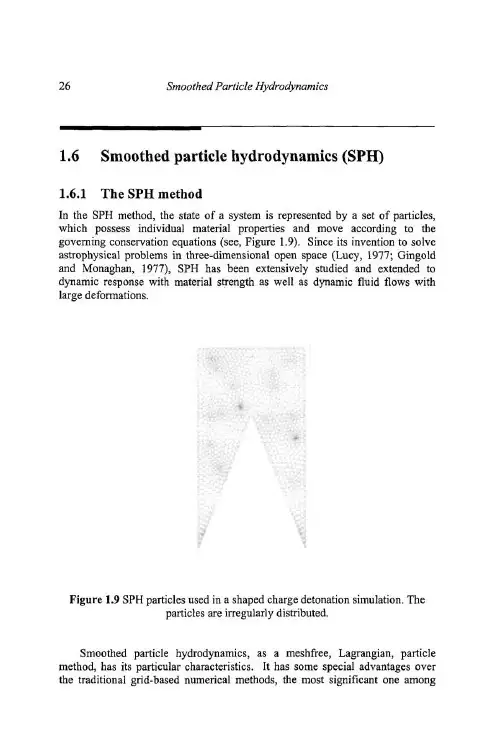
磁概念永磁材料:永磁材料被外加磁场磁化后磁性不消失,可对外部空间提供稳定磁场。
钕铁硼永磁体常用的衡量指标有以下四种:剩磁(Br)单位为特斯拉(T)和高斯(Gs) 1Gs =0.0001T将一个磁体在闭路环境下被外磁场充磁到技术饱和后撤消外磁场,此时磁体表现的磁感应强度我们称之为剩磁。
它表示磁体所能提供的最大的磁通值。
从退磁曲线上可见,它对应于气隙为零时的情况,故在实际磁路中磁体的磁感应强度都小于剩磁。
钕铁硼是现今发现的Br最高的实用永磁材料。
磁感矫顽力(Hcb)单位是安/米(A/m)和奥斯特(Oe)或1 Oe≈79.6A/m处于技术饱和磁化后的磁体在被反向充磁时,使磁感应强度降为零所需反向磁场强度的值称之为磁感矫顽力(Hcb)。
但此时磁体的磁化强度并不为零,只是所加的反向磁场与磁体的磁化强度作用相互抵消。
(对外磁感应强度表现为零)此时若撤消外磁场,磁体仍具有一定的磁性能。
钕铁硼的矫顽力一般是11000Oe以上。
内禀矫顽力(Hcj)单位是安/米(A/m)和奥斯特(Oe)1 Oe≈79.6A/m使磁体的磁化强度降为零所需施加的反向磁场强度,我们称之为内禀矫顽力。
内禀矫顽力是衡量磁体抗退磁能力的一个物理量,如果外加的磁场等于磁体的内禀矫顽力,磁体的磁性将会基本消除。
钕铁硼的Hcj会随着温度的升高而降低所以需要工作在高温环境下时应该选择高Hcj的牌号。
磁能积(BH)单位为焦/米3(J/m3)或高•奥(GOe) 1 MGOe≈7. 96k J/m3退磁曲线上任何一点的B和H的乘积既BH我们称为磁能积,而B×H的最大值称之为最大磁能积(BH)max。
磁能积是恒量磁体所储存能量大小的重要参数之一,(BH)max越大说明磁体蕴含的磁能量越大。
设计磁路时要尽可能使磁体的工作点处在最大磁能积所对应的B和H附近。
各向同性磁体:任何方向磁性能都相同的磁体。
各向异性磁体:不同方向上磁性能会有不同;且存在一个方向,在该方向取向时所得磁性能最高的磁体。


珊瑚礁地形上波浪传播变形的非静压数值模拟张其一;史宏达;高伟;李金峰【摘要】珊瑚礁广泛分布于我国南海等海域,具有重要的生态、旅游、港口和军事价值.波浪是珊瑚礁环境最重要的动力因素之一.基于非静压浅水方程波浪模型SWASH,模拟了典型岸礁地形上的波浪传播过程,并采用Demirbilek等的水槽实验数据分别对有效波高、波浪增水与爬高进行了验证,模拟结果与实测数据符合良好,展示了非静压模型在珊瑚礁地形上良好的适用性.通过波浪频率谱和波面小波谱,分析了波浪谱在该珊瑚礁地形上的演化规律,并揭示了礁坪上波浪能量从高频向低频转移的现象.本研究结果可为珊瑚礁环境动力研究以及相关的工程建设提供有益的参考依据.【期刊名称】《海岸工程》【年(卷),期】2017(036)004【总页数】9页(P1-9)【关键词】珊瑚礁;波浪传播;非静压模型;SWASH;小波分析【作者】张其一;史宏达;高伟;李金峰【作者单位】中国海洋大学工程学院 ,山东青岛266100;中国海洋大学工程学院 ,山东青岛266100;中交天津航道局有限公司 ,天津300450;中交天津航道局有限公司 ,天津300450【正文语种】中文【中图分类】P731.22珊瑚礁作为一种典型的海洋地貌形态,在深海和浅海区域均有分布。
根据其形式一般可以分为环礁、岸礁和堡礁。
珊瑚礁地形广泛分布于我国的台湾岛附近及南海海域,具有重要的港口、航运、生态、旅游、科研和军事价值。
近年来,随着国家对南海岛礁开发力度的提升,珊瑚礁动力环境的研究也逐步加深。
然而,由于珊瑚礁地形地貌特殊而复杂,其动力特点和形成机制尚待系统、深入地探究。
作为珊瑚礁环境的最主要动力,波浪在珊瑚礁地形上的传播和变形得到了国内外学者广泛的关注。
Gourlay[1]较早开展了规则波在珊瑚礁地形上传播变形的物理模型实验,并提出了非线性系数F co=来描述相对波高的变化规律:当非线性系数F co越小时,相对波高也越小。


摩托车术语整车类英文中文工具总汇Socket Wrench Double End Spanner PliersScrewdriverToolkitSocket Wrench Bar Service Bag Cutting Pliers Nipper Pliers Expansion Pliers Rubber Hammer Iron Hammer Copper Hammer 套筒扳手双头扳手钳子两用螺丝刀工具袋套筒杆资料袋钢丝钳尖嘴钳扩充钳橡皮锤铁锤铜锤Pawl Socket爪子套筒Feeler Gauge塞规Micrometer千分尺Dual-Meter百分表Cylinder Barometer缸压表Torque Wrench扭矩扳手Tire Barometer胎压表Vernier Caliper游标Motorized Gun电动枪整车设计参数Vehicle Category车辆类型Dimensional Drawing尺寸图Wheelbase轴距Unladen Mass空载质量Maximum Technically Permissible Mass最大技术同意质量MaximumTechnically Permissible Mass Declared by制造商申明的最大技术同意质量the ManufacturerGround Clearance 离地空隙车架ChassisLeft Decorative Plate Right Decorative Plate Hanger PivotEngine Hanger Finite Unit Model Stiffness车架左装修板右装修板吊架轴发动机吊架有限元模型刚度支架Main StandSide StandSide Stand Spring Side Stand Screw Side Stand Nut 主支架侧支架侧支架弹簧侧支架螺钉侧支架螺母Flange BoltMain Stand Bush Main Stand Spring凸缘螺栓主支架衬套主支架弹簧悬架SuspensionFront Shock Absorber Rear Shock Absorber Shock Absorber Sleeve悬架前减震后减震减震轴套转向系统Steering System Steering Angle Rake Angle Steering Axis TrailFront Ground Trail Rear Ground Trail 转向系统转向角倾斜角方向轴伸距前地面伸距后地面伸距True TrailSlip AngleReal TrailRight Handle ShieldLeft Handle ShieldFree Stroke of Throttle Handle Steering BearingThrottle ControlFront Light Cover Handlebar实质伸距滑动角实质伸距右手护套左手护套油门自由行程立管转向轴承油门控制前灯壳方向把灯具HeadlightHeadlight LensHigh BeamLow BeamFront/Rear Position Light 前大灯前大灯凸镜前大灯远光前大灯近光前/ 后地点灯Winker/Turn SignalFront/Rear Direction Indicator Winker CaseWinker BaseWinker CoverRear Registration Plate Lamp Tail LightTail Light CoverStop Light/LampBulbLight DiffusionLight DimmerHolderIlluminationMaximum IntensitySide Reflector 转向灯前/ 后转向灯转向灯后壳转向灯灯座转向灯罩后牌照灯尾灯尾灯罩制动灯灯泡光漫射灯光变换开关灯座照度最大照度侧反射器Rear Reflector 后反射器挡泥板Front/Rear FenderMud GuardWater GuardMounting Plate for Fender Rubber BushHexagon Bolt前/ 后挡泥板挡泥板挡水皮下挡泥定位板橡胶衬垫六角螺栓制动系统Disc Brake/Drum Brake Brake LeverBrake Pedal Hydraulic Reservoir Brake FluidBrake Shoe 盘式制动 / 鼓式制动制动杆制动踏板制动油缸制动液制动块Brake Spring CamBrake Rocker制动弹簧凸轮摇臂轮系Rear WheelFront WheelTireRimWheel HubAir NozzleTire ValveTire Valve CoreTire Valve ExtensionTire Valve Hole Misalignment Tire Valve Rubber PadTire Slip 后轮前轮轮胎轮辋轮毂气嘴轮胎气门嘴轮胎气门芯轮胎气门嘴伸出部分轮胎气门嘴孔地点未瞄准轮胎气门嘴胶垫轮胎同意滑动量Tire Slip ControlTire Slits=Tire SlotsTire SmokeTire SpinningTire SpreaderTire SqueakTire SquealTire StabilityTire Support PadTire Test Center=Tire Test Department Tire Testing EquipmentTire Test Rig=Tire Test StandTire Texture=Tire Belt CordCross PlyRadial Ply 轮胎滑差控制轮胎刀槽轮胎冒烟轮胎(打滑)空转轮胎张紧器轮胎行驶噪音轮胎转弯的声音。

Advanced Optical MaterialsIntroductionAdvanced optical materials are a class of materials that possess unique optical properties and are engineered to enhance light-matter interactions. These materials have revolutionized various fields such as photonics, optoelectronics, and nanotechnology. In this article, we will explore the different types of advanced optical materials, their applications, and the future prospects of this exciting field.Types of Advanced Optical MaterialsPhotonic CrystalsPhotonic crystals are periodic structures that can manipulate the propagation of light. They consist of a periodic arrangement ofdielectric or metallic components with alternating refractive indices. These structures can control the flow of light by creating energy bandgaps, which prohibit certain wavelengths from propagating through the material. Photonic crystals find applications in optical communication, sensing, and solar cells.MetamaterialsMetamaterials are artificially engineered materials that exhibit properties not found in nature. They are composed of subwavelength-sized building blocks arranged in a periodic or random manner. Metamaterials can manipulate electromagnetic waves by achieving negative refractive index, perfect absorption, and cloaking effects. These unique properties have led to applications in invisibility cloaks, super lenses, and efficient light harvesting.Plasmonic MaterialsPlasmonic materials exploit the interaction between light and free electrons at metal-dielectric interfaces to confine light at nanoscale dimensions. This confinement results in enhanced electromagnetic fields known as surface plasmon resonances. Plasmonic materials have diverse applications such as biosensing, photothermal therapy, and enhanced solar cells.Quantum DotsQuantum dots are nanoscale semiconductor crystals with unique optical properties due to quantum confinement effects. Their size-tunable bandgap enables them to emit different colors of light depending ontheir size. Quantum dots find applications in display technologies (e.g., QLED TVs), biological imaging, and photovoltaics.Organic Optoelectronic MaterialsOrganic optoelectronic materials are based on organic compounds that exhibit electrical conductivity and optical properties. These materials are lightweight, flexible, and can be processed at low cost. They find applications in organic light-emitting diodes (OLEDs), organic photovoltaics (OPVs), and organic field-effect transistors (OFETs).Applications of Advanced Optical MaterialsInformation TechnologyAdvanced optical materials play a crucial role in information technology. Photonic crystals enable the miniaturization of optical devices, leading to faster and more efficient data transmission. Metamaterials offer possibilities for creating ultra-compact photonic integrated circuits. Plasmonic materials enable the development of high-density data storage devices.Energy HarvestingAdvanced optical materials have revolutionized energy harvesting technologies. Quantum dots and organic optoelectronic materials are used in next-generation solar cells to enhance light absorption and efficiency. Plasmonic nanoparticles can concentrate light in solar cells, increasing their power output. These advancements contribute to the development of sustainable energy sources.Sensing and ImagingThe unique optical properties of advanced optical materials make them ideal for sensing and imaging applications. Quantum dots are used as fluorescent probes in biological imaging due to their bright emissionand excellent photostability. Metamaterial-based sensors offer high sensitivity for detecting minute changes in refractive index ormolecular interactions.Biomedical ApplicationsAdvanced optical materials have significant implications in biomedical research and healthcare. Plasmonic nanomaterials enable targeted drug delivery, photothermal therapy, and bioimaging with high spatial resolution. Organic optoelectronic materials find applications in wearable biosensors, smart bandages, and flexible medical devices.Future ProspectsThe field of advanced optical materials is rapidly evolving with continuous advancements being made in material synthesis, characterization techniques, and device fabrication processes. Thefuture prospects of this field are promising, with potential breakthroughs in areas such as:1.Quantum Optics: Integration of advanced optical materials withquantum technologies could lead to the development of quantumcomputers, secure communication networks, and ultra-precisesensors.2.Flexible and Wearable Electronics: Organic optoelectronicmaterials offer the potential for flexible and wearable electronic devices, such as flexible displays, electronic textiles, andimplantable medical devices.3.Optical Computing: Photonic crystals and metamaterials may pavethe way for all-optical computing, where photons replace electrons for faster and more energy-efficient data processing.4.Enhanced Optoelectronic Devices: Continued research on advancedoptical materials will lead to improved performance and efficiency of optoelectronic devices such as solar cells, LEDs, lasers, andphotodetectors.In conclusion, advanced optical materials have opened up newpossibilities in various fields by enabling unprecedented control over light-matter interactions. The ongoing research and development in this field promise exciting advancements in information technology, energy harvesting, sensing and imaging, as well as biomedical applications. The future looks bright for advanced optical materials as they continue to revolutionize technology and shape our world.。


十字形-维铁磁纳米结构中自旋波的动力学研究
自旋波是一种在铁磁材料中传播的磁激发,具有离散的能量和动量。
十字形-维铁磁纳米结构是一种具有十字形交叉结构的纳米磁体,它具有特殊的磁学行为和应用潜力。
在十字形-维铁磁纳米结构中研究自旋波的动力学可以通过多种实验和模拟方法来实现。
其中,动态磁力显微镜(MFM)是一种常用的实验手段,它可以通过在样品表面扫描探测自旋波的传播和耦合行为。
此外,通过谐振磁力光谱(FMR)和时间分辨磁光光谱(TRMOKE)等技术,也可以对自旋波的动力学特性进行研究。
在模拟方面,可以使用自旋动力学模拟方法,如蒙特卡洛法和微观动力学法等,来研究自旋波的动力学行为。
这些方法可以考虑晶格结构、相互作用强度和外部磁场等因素对自旋波的影响。
通过这些模拟方法,可以研究自旋波的传播速度、解析度和耦合行为等重要的动力学特性。
一维石墨烯超晶格上的氢吸附研究的开题报告
一维石墨烯超晶格是一种由一维石墨烯链的重复单元组成的周期性结构。
该结构有着良好的机械性能和导电性能,在能量存储和传输领域有着广泛的应用前景。
而氢气吸附材料则是清洁能源领域不可或缺的组成部分。
本文将研究一维石墨烯超晶格对氢气吸附的性能。
主要目的是通过计算模拟,研究超晶格结构对氢气吸附的影响,并探讨其吸附机理。
预计本文将从以下几个方面进行研究。
(1)建立一维石墨烯超晶格模型
通过建立一维石墨烯链的模型,通过周期性结构的重复单元,构建出一维石墨烯超晶格模型。
(2)计算氢气分子吸附能
采用第一性原理计算方法,对氢分子在超晶格结构上的吸附能进行计算,并探究吸附能与超晶格结构之间的关系。
(3)研究氢气吸附机理
通过分析氢分子在超晶格结构上的吸附状态和结构特征,探究氢气吸附的机理。
(4)对比分析不同超晶格结构
对比分析不同超晶格结构对氢气吸附的影响,探究不同结构之间的差异,为后续的实验研究提供理论基础。
通过对一维石墨烯超晶格上的氢吸附的研究,可以为新型清洁能源材料的设计提供理论基础和指导。
同时,该研究也有助于深入理解超晶格结构的特性和氢气的吸附机理,为相关领域的研究提供参考。
十字形-维铁磁纳米结构中自旋波的动力学研究
十字形-维铁磁纳米结构是近年来研究的热点之一,具有很好的应用
前景。
其中,自旋波的动力学行为是重要的研究内容之一。
首先,需要说明的是,自旋波是产生于铁磁性材料中的一种磁性激发,表示一种名为磁偏振量的矢量场的小幅振荡。
自旋波是一种具有波动性质
的自旋集体激发模式,能够在铁磁性材料中传递和传输磁矩。
对于十字形-维铁磁纳米结构,其自旋波的动力学行为与其他铁磁性
材料基本相同,但由于十字形-维铁磁纳米结构的几何形状不同,其自旋
波的传播和耗散行为则表现出明显的特征。
近几年的研究表明,十字形-维铁磁纳米结构中的自旋波具有非常低
的耗散率和非常高的波矢,因此可以用于高速磁信息传输等应用领域。
然而,由于其结构复杂性,目前对于自旋波在十字形-维铁磁纳米结构中的
行为和特性,还需要进一步的理论和实验研究。
PLEASE SCROLL DOWN FOR ARTICLEThis article was downloaded by: [Li, Qiang]On: 28 September 2008Access details: Access Details: [subscription number 903097187]Publisher Taylor & FrancisInforma Ltd Registered in England and Wales Registered Number: 1072954 Registered office: Mortimer House,37-41 Mortimer Street, London W1T 3JH, UKJournal of Experimental NanosciencePublication details, including instructions for authors and subscription information:/smpp/title~content=t716100757Study of coercive force for yZnFe 2O 4-(1 - y)CoFe 2O 4 magnetic nanoparticles systemQiang Li a ; Jian Li a ; Xianmin Chen a ; Shaona Han a ; Rongli Gao a aSchool of Physics, Southwest University, Chongqing, People's Republic of China Online Publication Date: 01 September 2008To cite this Article Li, Qiang, Li, Jian, Chen, Xianmin, Han, Shaona and Gao, Rongli(2008)'Study of coercive force for yZnFe 2O 4-(1 -y)CoFe 2O 4 magnetic nanoparticles system',Journal of Experimental Nanoscience,3:3,245 — 257To link to this Article: DOI: 10.1080/17458080802183635URL: /10.1080/17458080802183635Full terms and conditions of use: /terms-and-conditions-of-access.pdf This article may be used for research, teaching and private study purposes. Any substantial or systematic reproduction, re-distribution, re-selling, loan or sub-licensing, systematic supply or distribution in any form to anyone is expressly forbidden.The publisher does not give any warranty express or implied or make any representation that the contents will be complete or accurate or up to date. The accuracy of any instructions, formulae and drug doses should be independently verified with primary sources. The publisher shall not be liable for any loss,actions, claims, proceedings, demand or costs or damages whatsoever or howsoever caused arising directly or indirectly in connection with or arising out of the use of this material.Journal of Experimental Nanoscience Vol.3,No.3,September 2008,245–257Study of coercive force for y ZnFe 2O 4–(1Z y )CoFe 2O 4magnetic nanoparticles systemQiang Li,Jian Li *,Xianmin Chen,Shaona Han and Rongli GaoSchool of Physics,Southwest University,Chongqing,People’s Republic of China (Received 25June 2007;final version received 4May 2008)The coercive forces are taken out from the loops of magnetisation cycle for y ZnFe 2O 4–(1Ày )CoFe 2O 4mixed magnetic nanoparticles system (y is the volume fraction of ZnFe 2O 4particles in y ZnFe 2O 4–(1Ày )CoFe 2O 4magnetic nanopar-ticles mixed system).The results show that the coercive force of the system is increasing with the y decreasing and is interpreted by using particles chain model.The number of chains of particles under magnetic field is obtained by comparing the coercive force of the experiment and the theory of chain model.In y ZnFe 2O 4–(1Ày )CoFe 2O 4magnetic nanoparticles mixed system,the coercive force comes from ferrimagnetic CoFe 2O 4nanoparticles,and paramagnetic ZnFe 2O 4nano-particles make the chain length of the mixed magnetic system shorter than single CoFe 2O 4nanoparticles system.Keywords:magnetic nanoparticles;coercive force;interaction;chain1.IntroductionThe magnetic behaviour of magnetic orderly particles depends strongly on the particles’size.Small size effect of particles has influence not only on the macro-magnetic behaviour (such as saturation magnetisation),but also on the micro-interaction (reflected in the differences in magnetisation process).Ferrite nanoparticles MFe 2O 4(M ¼Co,Mn and Zn etc.two divalent metal ion)are relatively stable;they are the most important part of preparing ferrofluids,which can be regarded as extensions or branches of the ultrafine particles of the research field.The in-depth study on magnetic nanoparticles will promote the development of ferrofluids.The ferrite particles whose size is around 10nm are single domain particles,which can be regarded as a single magnetic moment.Under an external magnetic field,the magnetic moment of magnetic nanoparticles will tend to the external magnetic field direction,and with the strengthening of the external magnetic field,magnetisation gradually tends to saturation.This magnetisation process is closely related to the dipoles’interaction of inter-particles.In disperse systems (such as ferrofluids),the interaction of magnetic nanoparticles that affects magnetisation has been studied in both theory and experiment by many researchers and many models have been put forward,but*Corresponding author.Email:aizhong@ISSN 1745–8080print/ISSN 1745–8099online ß2008Taylor &FrancisDOI:10.1080/17458080802183635D o w n l o a d e d B y : [L i , Q i a n g ] A t : 02:42 28 S e p t e m b e r 2008a unified understanding of their mechanism has not yet been achieved [1–6].There is distribution of particles size in the real ferrofluids,and it is a polydispersed system [7].The properties of ferrofluids (magnetic property,microstructurer,viscosity and so on)are different from those of a monodispersed system,and there are many difficulties in discussing the mechanism on the properties.In recent years,there have been a few theoretical researches into bidispersed systems consisting of large and small size particles without size distribution [7–10],but such a system is hard to achieve in experiment.The magnetic moment m of single domain particles is proportional to volume V and the magnetic moment m of spherical particles can be expressed as:m ¼d 3M 6ð1Þwhere M is the particles’magnetisation and d is the particles’size.Therefore,the bi-system consisting of both large and small particles can also be regarded as a system consisting of stronger and weaker magnetic particles with different m from different d .Through the way that synthesising the system consisted of two different magnetic particles to study the bidispersed system,in other words,using the magnetic bidispersed system instead of the size bidispersed system,it is easier to discuss the property of nanoparticles system accurately by combining both experiments and theories.Bulk CoFe 2O 4is ferromagnetic,while bulk ZnFe 2O 4is anti-ferromagnetic.Fine particles of anti-ferromagnetic bulk materials may be paramagnetic [11].A mixture of two different magnetic nanoparticles is a kind of solid dispersed system,which is helpful to study the effect that interaction of particles has upon magnetic.In this article,the coercive force of y ZnFe 2O 4–(1Ày )CoFe 2O 4magnetic nanoparticles system (y ¼0,1,0.33,0.5,0.67,0.8)is measured and the role of weak magnetic particles in a system of magnetical bidispersion is studied.2.Experimental methods2.1.The preparation of the nanoparticlesWith FeCl 3Á6H 2O,ZnCl 2,Co(NO 3)2Á6H 2O,NaOH,HCl as raw materials,nanoparticles were prepared by chemical co-precipitation.The following procedure was used:(a)A proper proportion of NaOH solution was added to mixed solutions of ZnCl 2and FeCl 3by molar ratio 1:2and the solutions were then heated until boiling.The solutions were boiled for 10min and maintained at room temperature for 2h.Then by washing,acetone dehydration and drying process,ZnFe 2O 4powders were produced.(b)A proper proportion of NaOH solution was added to mixed solutions of Co(NO 3)2and FeCl 3by molar ratio 1:2and the solutions were then heated to boiling.The solutions were boiled for 3min and maintained at room temperature for 2h.Then by washing,acetone dehydration and drying process,CoFe 2O 4powders were produced.(c)0.5ZnFe 2O 4–0.5CoFe 2O 4(y ¼0.5)nanoparticles system was produced by fullymixing ZnFe 2O 4powders and CoFe 2O 4powders at volume ratio 1:1.246Q.Li et al.D o w n l o a d e d B y : [L i , Q i a n g ] A t : 02:42 28 S e p t e m b e r 20080.8ZnFe 2O 4–0.2CoFe 2O 4(y ¼0.8)nanoparticles system was produced by fully mixing ZnFe 2O 4powders and CoFe 2O 4powders at volume ratio 4:1.Similarly,we can obtain 0.33ZnFe 2O 4–0.67CoFe 2O 4(y ¼0.33)nanoparticles system and 0.67ZnFe 2O 4–0.33CoFe 2O 4(y ¼0.67)nanoparticles system.(d)X-ray diffraction (XRD,D/Max-RC)was used to analyse structures of the abovesamples,energy dispersive spectrometer of X-ray (EDX,Norton 8000)was used to analyse the atom ratio between M (Co,Zn)and Fe,and transmission electron microscopy (TEM,H-600)was used to observe the particle morphology and analyse/examine the particle size.2.2.The measurement of the magnetic propertiesHH-15vibrating sample magnetometer (VSM)was used to measure the specific magnetisation curves of the six samples at room temperature and the largest magnetic field was 0.95T.The specific saturation magnetisation of the CoFe 2O 4nanoparticles is estimated from the relation of s $1/H in high field [12].The magnetisation M is achieved byM ¼ Áð2Þwhere is the density of the nanoparticles.To the y ZnFe 2O 4–(1Ày )CoFe 2O 4particles system,the density is¼y  1þð1Ày Þ 2ð3Þwhere 1is the density of ZnFe 2O 4, 2is the density of CoFe 2O 4, 1¼5.32g cm À3and 2¼5.23g cm À3,respectively.3.Experimental results and analysis3.1.The XRD and EDX measurement of the particlesThe XRD spectra of ZnFe 2O 4and CoFe 2O 4particle samples are given in Figure 1.From Figure 1(a)and (b),it can be seen that the diffraction peak is broad while the particle size is very fine.By analysing XRD spectra of the two samples,it can be determined that the above two samples are ZnFe 2O 4and CoFe 2O 4particles,respectively.The crystallite size,D 311,was obtained,determined by the Scherr formula using the half-maximum width of the (311)X-ray diffraction line (Figure 1(a)and (b)):D XRDZnFe2O4¼4.05nm,D XRDCoFe2O4¼10.06nm.The atom ratio of about 1:2between M (Co,Zn)and Fe by EDX for both CoFe 2O 4and ZnFe 2O 4particles can be obtained.The quantitative results for the samples are listed in Table 1.3.2.The morphology and size of the particles from TEMTEM observation indicated that the morphologies of both the CoFe 2O 4and ZnFe 2O 4particles are basically spherical as shown in Figure 2.Journal of Experimental Nanoscience 247D o w n l o a d e d B y : [L i , Q i a n g ] A t : 02:42 28 S e p t e m b e r 2008Using statistical analysis from TEM photographs,the size distribution of CoFe 2O 4can be illustrated as particles shown in Figure 3(a).The median value of the particles’diameter is 12.76nm and the distribution function is as follows:f ðx ÞCoFe 2O 4¼1:1366xexp À4:06ðln x À2:55Þ2ÂÃ:ð4ÞThe size distribution of ZnFe 2O 4particles can be also illustrated as shown in Figure 3(b).The median value of the particles’diameter is 4.22nm and the distribution function is as follows:f ðx ÞZnFe 2O 4¼1:5341xexp À7:39ðln x À1:44Þ2ÂÃ:ð5ÞThe sizes from the TEM photographs measurements are larger than the X-ray measurements.3.3.Measurement of magnetisation curvesMeasurement results of the curves of magnetisation cycle for the six samples are shown in Figure 4.The coercive force H c is obtained from the magnetisation loops of the particles at room temperature,as shown in Table 2.Obviously,H c decreases as y increases.2030405060700408012016015422440511400311220c p s2θ(deg)20304050607004080120160200C P S440511422400311220111152θ(deg)(a)(b)Figure 1.(a)XRD spectra of ZnFe 2O 4particles and (b)XRD spectra of CoFe 2O 4particles.Table 1.The quantitative results of EDX.Element Atom%Atom%error Element Atom%Atom%error Fe 67.20þ/À1.19Fe 63.10þ/À1.14Co 32.80þ/À1.30Zn 36.90þ/À2.03Total100Total100248Q.Li et al.D o w n l o a d e d B y : [L i , Q i a n g ] A t : 02:42 28 S e p t e m b e r 2008The saturation magnetisation M s of CoFe 2O 4particles obtained by M $1/H relations at the high fields is 103A ÁM 2.ZnFe 2O 4particles are paramagnetic and M value is 103A ÁM 2at 0.95T.The critical diameter of the single-domain magnetic for cubic crystal system [13]:D c ¼9ffiffiffiffiffiffiffiAKp M s:ð6Þ012340.00.51.01.52.0f (l n x )(=d f )/d l n x )lnxFigure 3.The size distribution for the (a)CoFe 2O 4particles and (b)ZnFe 2O 4particles..experiment values of ZnFe 2O 4particles;.experiment values of CoFe 2O 4particles;(—)curves ofdistribution.(a)(b)Figure 2.TEM photographs of (a)CoFe 2O 4particle and (b)ZnFe 2O 4particle.Journal of Experimental Nanoscience 249D o w n l o a d e d B y : [L i , Q i a n g ] A t : 02:42 28 S e p t e m b e r 2008−1.0−0.50.00.51.0−400−300−200−1000100200300400M (k A /m )B(T)−1.0−0.50.00.51.0B(T)−1.0−0.50.00.51.0B(T)−1.0−0.50.00.51.0B(T)−1.0−0.50.00.51.0B(T)−1.0−0.50.00.51.0B(T)−15−10−5051015M (k A /m )−300−200−1000100200300M (K A /m )−200−150−100−50050100150200M (k A /m )−90−60−300306090M (K A /m )−80−60−40−20020406080M (k A /m )(a)(b)(c)(d)(a)(f)Figure 4.The magnetisation loops of y ZnFe 2O 4–(1Ày )CoFe 2O 4mixed magnetic nanoparticles system,(a)CoFe 2O 4particles,(b)ZnFe 2O 4particles,(c)0.33ZnFe 2O 4–0.67CoFe 2O 4particles,(d)0.5ZnFe 2O 4–0.5CoFe 2O 4particles,(e)0.67ZnFe 2O 4–0.33CoFe 2O 4particles and (f)0.8ZnFe 2O 4–0.2CoFe 2O 4particles.Table 2.The coercive force H c measured by VSM for y ZnFe 2O 4–(1Ày )CoFe 2O 4nanoparticles system mixed.y00.330.500.670.801H c (kA m À1)44.4743.7043.6539.3736.37250Q.Li et al.D o w n l o a d e d B y : [L i , Q i a n g ] A t : 02:42 28 S e p t e m b e r 2008where K is the anisotropy constant,M s is the saturation magnetisation,A is the exchange constant and can be estimated from A %k B T c /a ,where k B is the Boltzmann constant,T c is the Curie temperature,a is the crystal lattice constant.When the values of bulk CoFe 2O 4are substituted into Equation (6)(K ¼1.8Â106erg cm À3,M s ¼400Gs,T c ¼793K,a ¼0.838nm),we can obtain D c ¼274.513nm.At room temperature,the superparamagnetic critical size of CoFe 2O 4particles is about 14nm [14].The range of the size is 4.6–36.8nm for CoFe 2O 4particles diameter measured.Therefore,the CoFe 2O 4particles consist of ferromagnetic and superparamagnetic particles.The ratio of superparamagnetic particles in CoFe 2O 4particles number can be obtained asZ 140f ðx ÞCoFe 2O 4d x ¼Z 1401:1366x exp ½À4:06ðln x À2:55Þ2 d x ¼0:6:This shows that the CoFe 2O 4particles prepared are single domain ones.Thesuperparamagnetic particles number is 60%and the ferromagnetic particles number is 40%at room temperature.4.Discussion4.1.Interaction energy the particlesAccording to the diameter distribution function of CoFe 2O 4nanoparticles (4),the average magnetic moment is [15]m h i ¼ 6M s Z 1x 3f ðx Þd x¼6:89Â10À19ðA m 2Þ:ZnFe 2O 4particles are paramagnetic and the greatest average magnetic moment in themagnetic field ism h i ¼6M 0:95T Z 10x 3f ðx Þd xwhere M 0.95T is the magnetisation at 0.95T.Substituting M 0.95T and ZnFe 2O 4diameterdistribution function (5),thusm h i ¼7:61Â10À22ðA m 2Þ,obviously,the average magnetic moment between CoFe 2O 4particles is far bigger than the biggest magnetic moment of ZnFe 2O 4particles.The interaction of single-domain magnetic particles can be regarded as the interaction of magnetic dipole.Interaction energy between i and j magnetic dipole is expressed [16]by:w ¼ 0m i m j =4 r 3ij cos ð i À j ÞÀ3cos i cos j ÂÃð7Þwhere 0is the vacuum permeability,r ij is the particles’distance, i , j are the anglebetween magnetic moment and central connections line.When i ¼ j ¼0,the interactionJournal of Experimental Nanoscience 251D o w n l o a d e d B y : [L i , Q i a n g ] A t : 02:42 28 S e p t e m b e r 2008energy of two CoFe2O4dipole particles(diameter12.76nm)linked by head-to-tail(r ij¼a), can be calculated as about2.63Â10À20J.When the magnetic moment of ZnFe2O4is the largest of all,the interaction energy of two ZnFe2O4dipole particles(diameter4.22nm)is about1.14Â10À24J.While one CoFe2O4particle with m¼6.89Â10À19(A m2)and one ZnFe2O4particle with m¼7.61Â10À22(A m2)are linked by head-and-tail(r ij¼(diameter of CoFe2O4particlesþdiameter of ZnFe2O4particles)/2),the interaction energy is about 1.04Â10À22J.At room temperature,the thermal energy is about k B T¼4.14Â10À21J. Therefore,it can be known that only the dipole interaction of CoFe2O4particles would be larger than the thermal energy,so that the chain of CoFe2O4particles will form in the magnetisation process[17].So,a system mixed with both CoFe2O4and ZnFe2O4particles can be called a system of magnetical bidispersion.4.2.The coercive forceIf there is no interaction between particles,the magnetisation M of the mixture containing N types of particles can be expressed[18]byMðBÞ¼P Nn¼1M nðBÞÈVnP Nn¼1ÈVnð8Þwhere M n is the magnetisation,andÈVn is the volume fraction of the n particle.Here,ÈVn has the same meaning as y and(1Ày)for y ZnFe2O4–(1Ày)CoFe2O4nanoparticles system.Thus,the remanence of y ZnFe2O4–(1Ày)CoFe2O4nanoparticles system mixed isM0rðyÞ¼ð1ÀyÞM r,Coð9Þwhere M r,Co is the remanence of the CoFe2O4nanoparticles(i.e.y¼0in y ZnFe2O4–(1Ày)CoFe2O4system).So,the remanence for M0r of y ZnFe2O4–(1Ày)CoFe2O4nanoparticles system mixed can be calculated by Equation(9),as shown in Table3.For comparison,the experiment values are also shown in Table3.Obviously,with y increasing,and the CoFe2O4particle volume fraction deceasing,theexperiment value M r is much less than the calculation value M0r of the remanence.But,itshould be noticed that the coercive force decreases as y increases(Table2).So,it can be judged that there is interaction in y ZnFe2O4–(1Ày)CoFe2O4nanoparticles mixed system. The coercive force can be related to the aggregate of the CoFe2O4nanoparticles,and ZnFe2O4nanoparticles can prevent CoFe2O4nanoparticles from aggregating in the nanoparticles mixed system[19].Therefore,the coercive force can be discussed from the chain aggregate model.Table3.The calculation and experiment value of the remanence for y ZnFe2O4–(1Ày)CoFe2O4 nanoparticles system.Y0.000.330.500.670.80 1.00M0r (kA mÀ1)25668.7451.3033.0620.520M r(kA/m)25669.2047.4120.7313.340|M rÀM0r |Â100/M0r(%)00.677.5837.3035.010252Q.Li et al.DownloadedBy:[Li,Qiang]At:2:4228September20 8If there is no external magnetic field,the intrinsic magnetic moment of ferromagnetism or ferrimagnetism nanoparticles will be random in orientation.Under the magnetic field,the magnetic moment of the nanoparticles will have a tendency to link along the direction of the magnetic field.Because the interaction energy of CoFe 2O 4particles linked by head-and-tail is larger than the thermal energy,CoFe 2O 4particles form a chain-like aggregate structure.When the magnetic field increases towards the negative direction,the magnetic moment along the positive direction will reverse first until the magnetic moments are opposite to the negative direction;then the corresponding magnetic field is the coercive force of the system.The magnetic reversal of the chain of spheres may have two mechanisms.One is the magnetic moment parallel rotation mechanism;the other is the symmetric fanning mechanism [20],as shown in Figure 5.In the two models of Figure 5,the spheres are all isolated;no consideration of their magnetic anisotropy is taken and,if it is assumed the particles are idealistic contacts,there only exists the magnetic dipole interaction of particles.In order to calculate the coercive force of spheres’chain under the magnetic field,first of all the total energy of the chain should be taken into account.Disregarding magnetic anisotropy energy,the total energy of the chain is only composed of interaction energy of both the interdipoles and between the dipoles and magnetic field.The total energy is the function of angle between magnetic moment and external magnetic field.Coercive force can be obtained from the energy relationship [20].In order to simplify the discussion,assume the magnetic moment as the average magnetic moment.Let the number of particles in a chain be n .The total energy can be expressed in parallel rotating mechanism as:w n ¼ð 0m 2=4 a 3ÞnK n ð1À3cos 2 Þþn 0mH cosð10ÞH cH cHH(b)(a)Figure 5.Rotating magnetic moment parallel mechanism inversion (a)and symmetric magnetic moment of the fan inversion mechanism (b).Journal of Experimental Nanoscience 253D o w n l o a d e d B y : [L i , Q i a n g ] A t : 02:42 28 S e p t e m b e r 2008whereK n ¼P nj ¼1ðn Àj Þ3:In the magnetisation process,the magnetic moment will rotate as the magnetic field increases.The conditions of the balance are@w n@¼0:From Equation (10)we can obtain@w n@¼ð 0m 2=4 a 3ÞnK n ð6cos sin ÞÀn 0mH sin ¼0:Thus,H ¼ðm =4 a 3Þ6K n cos :ð11ÞWhen the magnetic moment of the chain of spheres is in complete reversal, ¼ ,the coercive force can be expressedH c,n ¼ðm =4 a 3Þ6K n :ð12ÞIn the symmetric fanning mechanism,the total energy can be expressed as:w n ¼ð 0m 2=4 a 3ÞnL n ðcos 2 À3cos 2 Þþð 0m 2=4 a 3ÞnM n ð1À3cos 2 Þþn 0mH cosð13ÞwhereL n ¼X12ðn À1Þj 12ðn þ1Þj ¼1n Àð2j À1Þ½ =n ð2j À1Þ3M n ¼X12ðn À2Þj 12nj ¼1ðn À2j Þ=n ð2j Þ3L n þM n ¼K n :Using the same method with the parallel rotating mechanism,we can obtain the coercive force of symmetric fanning reversal mechanism asH c,n ¼ðm =4 a 3Þð6K n À4L n Þ:ð14ÞFor single CoFe 2O 4particles,according to Equations (12)and (14),the relationship between particles number in a chain n and coercity H c can be calculated for two mechanisms respectively.The partial results calculated are listed in Table 4.From Table 4,it can be seen that,as the particles number in the chain increases,the coercive force becomes higher and higher.In the magnetic moment parallel reversal mechanism and the symmetry fanning reversal mechanism,the coercive force of the former is larger than the latter.The coercive force of CoFe 2O 4can be obtained as H C ¼44.47kA m À1from the paring the theory result of the above twoD o w n l o a d e d B y : [L i , Q i a n g ] A t : 02:42 28 S e p t e m b e r 2008models,it can be known that the experimental result is consistent with the symmetry fanning reversal mechanism and that the corresponding number of particles is about 64.In y ZnFe 2O 4–(1Ày )CoFe 2O 4magnetic nanoparticles mixed system,ZnFe 2O 4is weak magnetic particles and its coercive force is pared with the magnetic of0.00.20.40.60.81.0363840424446(1−y)nH c (k A /m )102030405060Figure 6.The relations of the coercive H c versus the CoFe 2O 4particle volume fraction (1Ày ),and versus CoFe 2O 4particles number in a chain n for the symmetry fanning reversal model of chain.–H c versus (1Ày ),*–H c versus n .Table 4.The relationship between the particles number in a chain n and coercive force H c .H c (kA m À1)n A B 100245.5115.17788.9435.51891.4036.70993.3337.641094.8938.4039105.6043.6964107.0844.42100107.9144.841000109.2645.5110,000109.3945.58100,000109.4045.58A –parallel reversal mechanism of magnetic moment;B –symmetry fanning reversal mechanism of magnetic moment.D o w n l o a d e d B y : [L i , Q i a n g ] A t : 02:42 28 S e p t e m b e r 2008CoFe 2O 4,the magnetic of ZnFe 2O 4can be neglected.For the bidispersed system constituted with strong and weak magnetic nanoparticles,strong magnetic CoFe 2O 4particles may form a chain of spheres aggregating which present in a ‘sea’of weak magnetic ZnFe 2O 4particles [21].Therefore,the coercive force of the y ZnFe 2O 4–(1Ày )CoFe 2O 4magnetic nanoparticles system is still produced by chains of CoFe 2O 4.According to the magnetic moment symmetry fanning reversal mechanism and the experimental results in Table 2,we can see that when the coercive force of 0.33ZnFe 2O 4–0.67CoFe 2O 4in experiment is 43.70kA m À1,the corresponding number of particles in the chain is 39;that when the coercive force of 0.5ZnFe 2O 4–0.5CoFe 2O 4in experiment is 43.65kA m À1,the corresponding number of particles in the chain is 29;that when the coercive force of 0.67ZnFe 2O 4–0.33CoFe 2O 4in experiment is 39.37kA m À1,the corresponding number of particles in chain is 20,and that when the coercive force of 0.8ZnFe 2O 4–0.2CoFe 2O 4in experiment is 36.37kA m À1,the corresponding number of particles in chain is only 8.In Figure 6,the relations of coercive force H c versus n and versus (1Ày )are shown.Clearly,both relations are similar and n has a linear relation with (1Ày ).This shows that the length of the CoFe 2O 4particles chains becomes shorter because of ZnFe 2O 4particles mixing in the y ZnFe 2O 4–(1Ày )CoFe 2O 4particles system.5.ConclusionsThe size of CoFe 2O 4nanoparticles prepared is about 12.76nm,while the particles size of prepared ZnFe 2O 4is about 4.22nm and the particles size of ZnFe 2O 4is only one-third of CoFe 2O 4.y ZnFe 2O 4–(1Ày )CoFe 2O 4nanoparticles mixed system is a typical system of magnetism bidispersed.In this system,the coercive force merely comes from strong magnetic CoFe 2O 4particles.From the characteristics of both the coercive force H c decreasing and the remanence M r deviating from the calculation value with the particle volume fraction of ZnFe 2O 4particles y increasing as well as the average interaction energy of between the CoFe 2O 4particles stronger than k B T ,it can be judged that the coercive force is in relation to CoFe 2O 4nanoparticles aggregating for the y ZnFe 2O 4–(1Ày )CoFe 2O 4(05y 51)nanoparticles system.Under the magnetic field,the strong magnetic particles would form a chain-like structure.The number of particles in a chain can be obtained from the coercive paring the CoFe 2O 4nanoparticles with y ZnFe 2O 4–(1Ày )CoFe 2O 4nanoparticles mixed system,we can know that weak magnetic particles make the chain length of particles shorter.This accords with the light transmission change law of ferrofluids made up of similar systems,which will be reported in another paper.Therefore,we can infer that speciality of ferrofluids of magnetism bidispersion may be different from one of magnetism monodispersion.This will be further researched.AcknowledgementsThe work is supported by Nature Science Foundation of Chongqing,China,and Development Foundation of Southwest of China Normal University,China.D o w n l o a d e d B y : [L i , Q i a n g ] A t : 02:42 28 S e p t e m b e r 2008。
椭圆纳米盘中磁涡旋结构的方位角自旋波模式∗吕刚;曹学成;秦羽丰;王林辉;厉桂华;高峰;孙丰伟;张红【期刊名称】《物理学报》【年(卷),期】2015(0)21【摘要】In comparison with uniformly magnetized states, vortex structures demonstrate a rich frequency spectrum of spin-wave (SW) excitations. However, a detailed theoretical description of the magnetic modes is generally still a challenge due to the difficulty of analytic calculation, except for the well-defined symmetric circular states. In contrast, the method of micromagnetic simulations combined with Fourier analysis is shown to be very powerful for gaining insight into the nature of magnetic excitation modes. Vortex excitation modes have been reported to be directly influenced by the geometric symmetry of the elements and/or the nature of the initial perturbation of pulse field. In order to understand how the reduced symmetry affects the vortex SW modes, we perform the micromagnetic simulations on vortex modes excited in a submicron-sized thin ellipse. In order to excite the spin-wave modes, a short in-plane Gaussian field pulse is applied along the short axis direction. After the pulse, the off-centered vortex core moves following an elliptical trajectory around its equilibrium position. Simulations provide the time evolution of the local magnetizations (at each discretization point) and dynamics of the spatially averaged magnetization. To determine the mode frequencies, thespectrum is obtained from the average magnetization through Fourier transformation from time domain the frequency domain. By means of Fourier analysis, a variety of azimuthal SW modes can be observed in the excitation spectrum. The ellipse in single vortex state has a twofold rotational symmetry with a rotation ofπaround the z-axis (out-of plane) and can be described by the C2 group. The observed azimuthal modes can be divided into two categories according to their symmetry. Two modes occur alternately with increasing azimuthal number, indicating that the magnetic excitation modes remain to keep the symmetry of the ellipse structure. Their frequencies are found to increase linearly with the azimuthal index number. An increase of the SW frequency with increasing number of nodal planes is rather well known, which results from the competition between exchange and dipolar energy terms. According to the temporal e volution of the ellipse’s spatially averaged energy densities, our micromagnetic simulation shows that the average exchange energy is significantly higher than the magnetostatic energy, suggesting that the exchange interaction plays a more important role in the excitation modes. The exchange energy density is mainly focused on the core origin while the largest contribution of the magnetostatic energy is distributed near the long axis. Thus, we can conclude that the exchange interaction provides the principal contribution to the vortex energy in such small ellipses with a single vortex state, resulting in the increasing frequency versus the azimuthal number, that is observed.【总页数】5页(P1-5)【作者】吕刚;曹学成;秦羽丰;王林辉;厉桂华;高峰;孙丰伟;张红【作者单位】山东农业大学,信息科学与工程学院,泰安271018;山东农业大学,信息科学与工程学院,泰安 271018;山东农业大学,信息科学与工程学院,泰安271018;山东农业大学,信息科学与工程学院,泰安 271018;山东农业大学,信息科学与工程学院,泰安 271018;山东农业大学,信息科学与工程学院,泰安271018;山东农业大学,信息科学与工程学院,泰安 271018;山东农业大学,信息科学与工程学院,泰安 271018【正文语种】中文【相关文献】1.椭圆纳米薄膜的自旋波本征特性研究 [J], 张光富;张学军;邓杨保2.末端形状对磁纳米薄膜自旋波模式特性的影响 [J], 张光富;张学军;蒋练军3.纳米盘中磁涡旋核极性反转机制的研究 [J], 李化南;李东飞4.自旋波在十字交叉形磁性纳米线中的微磁模拟研究 [J], 张佳超;王瑞方5.纳米磁多层结构中电流驱动自旋波发射 [J], 陈培毅;胡九宁;任敏;张磊;邓宁因版权原因,仅展示原文概要,查看原文内容请购买。
a r X i v :a s t r o -p h /0408388v 2 25 A u g 2004Magneto-driven Shock Waves in Core-Collapse Supernova Tomoya Takiwaki 1,Kei Kotake 1,Shigehiro Nagataki 2,and Katsuhiko Sato 1,31Department of Physics,School of Science,the University of Tokyo,7-3-1Hongo,Bunkyo-ku,Tokyo 113-0033,Japan2Yukawa Institute for Theoretical Physics,Kyoto University,Kyoto 606-8502,Japan 3Research Center for the Early Universe,School of Science,the University of Tokyo,7-3-1Hongo,Bunkyo-ku,Tokyo 113-0033,Japan takiwaki@utap.phys.s.u-tokyo.ac.jp ABSTRACT We perform a series of two-dimensional magnetohydrodynamic simulations of the rotational core-collapse of a magnetized massive star.We employ a realistic equation of state and take into account the neutrino cooling by the so-called leak-age scheme.In this study we systematically investigate how the strong magnetic field and the rapid rotation affect the propagation of the shock waves.Our results show that in the case of the strong initial poloidal magnetic field,the toroidal magnetic field amplified by the differential rotation,becomes strong enough to generate a tightly collimated shock wave along the rotational axis.On the other hand,in the case of the weak initial magnetic field,although the differential rotation amplifies toroidal magnetic field over the long rotational period,the launched shock wave is weak and the shape of it becomes wider.The former case is expected to be accompanied by the formation of the so-called magnetar.Our models with rapid rotation and strong magnetic field can create a nozzle formed by the collimated shock wave.This might be the analogous situation of the collapsar that is plausible for the central engine of the Gamma-Ray Bursts.Subject headings:supernovae:collapse,rotation —magnetars:pulsars,magnetic field —methods:numerical —MHD —gamma rays:bursts1.IntroductionThe study of collapse driven supernovae is important not only for itself but also for the understanding of other process of astrophysical relevance,such as nucleosynthesis of heavyelements and chemical evolutions in the universe(e.g.,Arnett1996),radiation of neutrinos in the universe(Raffelt2002),the gravitational waves(Andersson2003),and possibly gamma-ray bursts(GRB)and hypernovae(MacFadyen&Woosley1999).In spite of its importance and extensive investigations done so far,the explosion mechanism has not been clarified yet.Except for the special cases,the shock wave generated by the core bounce stalls and becomes an accreting shock in the core.Although neutrino heating are expected to revive the shock wave and lead to the successful explosion(Wilson1985),recent theoretical studies that elaborate the neutrino transport method and detailed microphysics and/or general relativity,failed to produce explosions(Rampp&Janka2000;Liebend¨o rfer,Mezzacappa,& Thielemann2001;Thompson,Burrows,&Pinto2003;Buras,Rampp,Janka,&Kifonidis 2003).However,it should be noted that most of them assume spherical symmetry(see, however,Buras et al.2003).On the other hand,there are convincing observations,which require the revision of the spherically symmetric stellar collapse.Rather common correlation between the asymmetry and the collapse-driven supernovae has been reported by the observation of the polarization (Wang et al.2002).It is also well known that SN1987A is globally asymmetric(Cropper et al.1988;Papaliolis et al.1989),which is directly confirmed by the images of the Hubble Space Telescope(Plait,Lundqvist,Chevalier,&Kirshner1995).The observed light curve also supports jet-like explosion(Nagataki,Hashimoto,Sato,&Yamada1997;Nagataki2000). The asymmetry is likely to have originated from the core dynamics(Khokhlov et al.1999). Provided the facts that the progenitors of the collapse-driven supernovae are a rapid rotator on the main sequence(Tassoul1978)and that the recent theoretical studies suggest a fast rotating core prior to the collapse,it is important to incorporate rotations in simulations of core collapse(Heger,Langer,&Woosley2000).In addition,after the discovery of pulsars,it was reasonable to explore the issue of whether or not the rotation and magneticfields associated with pulsars could be a signifi-cant factor in the explosion mechanism.So far there have been some works devoted to the understanding of the effect of rotation and magneticfield on the supernova explosion mech-anism(Leblanc&Wilson1970;Mueller&Hillebrandt1981;Bodenheimer&Woosley1983; Symbalisty1984;M¨o nchmeyer et al.1989;Yamada&Sato1994;Fryer&Heger2000;Ko-take,Yamada,&Sato2003).The magnetocentrifugal jets generated by the strong toroidal magneticfields in stellar collapse may explain why all core collapse supernovae are found to be substantially asymmetric and predominantly bipolar(Wheeler,Meier,&Wilson2002). With the typical dipolefields of1012G and rotation periods of several tens of milliseconds, however implying electro dynamic power of only≈1044−1045ergs−1,a strong robust explo-sion seemed unlikely.Several factors,such as observation of magnetar(Duncan&Thomp-son1992),may lead to a need to reexamine the conclusion.For analyzing the origin of the strong magneticfield,it is necessary to investigate the magnetohydrodynamic processes such as magnetorotational instability(MRI)and thefield line wrapping mechanism(Ostriker &Gunn1971;Bisnovatyi-Kogan1971;Bisnovatyi-Kogan&Ruzmaikin1976;Kundt1976; Balbus&Hawley1998;e.g.Meier,Epstein,Arnett,&Schramm1976;Akiyama,Wheeler, Meier,&Lichtenstadt2003).These processes strongly depend on the configuration and the strength of the magneticfields.We think that it’s still worth investigating the model of strong magneticfield and rapid rotation those have not been considered sufficiently so far.It should be mentioned that such models may be related to some theoretical models of GRBs and magnetar(Proga,MacFadyen,Armitage,&Begelman2003;Lyutikov,Pariev,& Blandford2003).By changing the strength of rotation and the poloidal magneticfields in a parametric manner,we investigate how the rapid rotation and the strong magneticfields affect the property of the shock waves and the explosion energy.By so doing,we hope to un-derstand the difference of the hydrodynamic behaviors between our models and the models for the canonical supernovae discussed so far.We describe the numerical method and the initial model in the next section.In the third section,we show the numerical results.The summary and some discussions are given in the last section.2.Method of Calculation2.1.Basic EquationsThe numerical method for magnetohydrodynamic(MHD)computations employed in this paper is based on the ZEUS-2D code(Stone,Mihalas,&Norman1992).The basic equations for the evolution are written as follows,DρD t =−∇P−ρ∇Φ+1D t e∂t=∇×(v×B),(4)△Φ=4πGρ,(5)whereρ,P,v,e,Φ,B,Lνare the mass density,the gas pressure including the radiation pres-sure from neutrino’s,thefluid velocity,the internal energy density,the gravitational po-tential,the magneticfield and the neutrino cooling rate,respectively.We denote Lagrange derivative,as DZ40X2+X20changing the total angular momentum and strength of magneticfield by varying the value ofΩ0and B0.The model parameters are given in Table1.The models are named after this combination,with thefirst letters,B12,B10.5,B9,B0,representing strength of initial magneticfield,the following letter,TW1,TW2,TW4representing the initial T/|W|.Here T/|W|indicates the ratio of rotational energy to absolute value of gravitational energy.3.Numerical Results3.1.The Hydrodynamic FeaturesWe willfirst summarize some important magnetohydrodynamic aspects which are com-mon to our models.The time evolution of our models can be specified by the three stages. Thefirst stage is between the onset of the core collapse and the core bounce.The matter falls to the center of the core everywhere.Therefore the magneticfields frozen into the matter are compressed in this stage.Next we call the epoch from the core bounce to the propagation of the shock waves as the second stage.Since the rotation prevents the matter from infalling around the equatorial plane,the matter near the rotational axis falls more quickly.The core bouncefirst occurs near the axis.High entropy regions are generated near the rotational axis,and they begin to propagate along the axis.The toroidal magneticfield is produced by the MHD processes in the shock wave.The amplification of the magnetic fields is discussed elaborately in subsection3.2.After the second stage,the shock wave is generated and propagates outward.We call this stage as the third stage.The properties of the shock waves are different among the models,however it is common that the toroidal magneticfield is transferred by the shock,see the top panels of Figure1.Especially in the models of the moderate magneticfield such as B10.5TW1,B10.5TW2and B10.5TW4,we found unique hydrodynamical features.The shock wave tends to stall in these models.After the stall the hydrodynamical features resemble to those in the second stage.The matter falls easily near the rotational axis,and the weaker shock wave is generated by the difference of the magnetic and the matter pressures between inside and outside of the shock wave.After the launch of the shock the epoch goes to the third epoch.The second stage and the third stage are repeated.The arguments of specific behaviors among models are starting in the following.We show the differences of each model in the three stages mentioned above.Some of thefinal profiles are presented in Figure2.It can be clearly seen in thefigure that there is a variety offinal state of shocks.We investigate the origin of this variety in the following.Since the rotation does not affect qualitative features in our computation so much,we mainly focus on the hydrodynamic features of each models caused by the initial strength of the magneticfield.In the strong magnetic models such as B12TW1,B12TW2,and B12TW4,tightly colli-mated jet-like shock waves are found at the third stage.Strong hoop stress is produced by thefield wrapping at the launch of the shock wave.The launched shock waves are pushed by the strong magnetic pressure,and propagate along the rotational axis,while keeping its shape collimated.The discussion for the collimation is given in the last of section3.2. The matter around the polar axis is expelled by the collimated jet-like shock waves.These dynamic behaviors are seen in Figure1in the case of B12TW4.In all stages there are no qualitative differences among these three models,such as shape of the jet and the remaining configuration of the matter.A major quantitative difference is the explosion energy discussed in section3.3.On the other hand,the shock waves become less collimated near the rotational axis in the weak magnetic models such as B9TW4,B9TW2,B9TW1,B0TW4,B0TW2and B0TW1. The prolate shock waves at the core bounce become rather spherical after the shock stalls. This is caused by the magnetic and the matter pressure.The difference among them is seen at a later stage rather.In the case of the weak rotation,the shock front revived by the magnetic and the matter pressure propagates rather spherically.On the other hand,in the case of the strong rotation the magnetic pressure produced by thefield wrapping pushes the matter along the rotational axis at the launch of the shock.However this weak prolate shock wave becomes spherical soon due to weak hoop stress.In the case of the moderate magneticfields such as B10.5TW4and B10.5TW2,the evolutions of the shock waves are rather complicated,see the right panels of Figure3.In these cases,jet-like shock waves are launched along polar axis,and stall very soon.20ms after the shock-stall,the shock wave is found to be revived due to the magnetic and the matter pressure and propagates along the rotational axis again(right top).However in this case,the hoop stress is not strong enough to keep the collimation of the prolate shock wave (right middle).Then the prolate shock wave becomes spherical.The shock front propagates repeating these behaviors(right bottom),the shape of shock wave becomes spherical in the end.On the other hand,in the case of B10.5TW1(see the left panels of Figure3),the stalled jet-like shock waves launched along polar axis are revived by the matter pressure (left top).The weak rotation makes the second bounce robust as the weak rotation makes first bounce robust.The jet-like shock propagates along the rotational axis strongly(left middle).After the shock propagates along rotational axis,this robust shock wave becomes wider(left bottom).The strength of the rotation rate makes these differences,i.e.in the case of weak rotational model,the strong shock wave is generated.This shock front propagates before the matter behind the shock wave expands.In the rapid rotating model the weakshock waves is likely to stall and expand due to the matter and magnetic pressures.For the analysis of these behaviors,we focus on the value of plasma beta which is ratio of the gas pressure to the magnetic pressure in the following section.3.2.Behavior of Magnetic Field and Degree of CollimationWe explain how the magneticfields affect the propagation of the shock waves in this subsection.First we briefly explain two MHD processes so-called magnetorotational insta-bility(MRI)andfield wrapping.We focus on one of the MRI of the vertical component of the magneticfield,because in our simulation initial magneticfield is vertical.It is noted that this MRI produces the X component of the magneticfield.This MRI is important because the onset of the MRI requires the differential rotation of the core,i.e.dΩ∂X −1(Balbus&Hawley1998).If this value is constant,the MRI process amplifies the X component of the magneticfield exponentially.As for thefield wrapping,it winds up poloidal magneticfield along axis,and generate toroidal magnetic field.This process also requires the differential rotation.It’s characteristic time scale is τWRAP=4π ∂BφBφ −1=4π B X∂X +B Z∂Z −1which is derived from induction equa-tion(e.g.Meier,Epstein,Arnett,&Schramm1976).The definition ofτWRAP shows that τWRAP becomes short if the poloidal magneticfield dominates toroidal component.It means that MRI can increase the seed poloidal component of magneticfield which amplifies the toroidal magneticfield due to thefield wrapping.It should be noted that since our simula-tion assumes axisymmetry,the poloidal component can not be produced from the instability of the toroidal component.We show how magneticfields are amplified in each stage by comparing the growth time-scale of MRI andfield wrapping(see Figure4).In thefirst stage,the typical time-scale for this stage is less than200ms after the onset of the gravitational collapse.Although the initial magneticfields are parallel to the rotational axis,the X component is found to be formed by the infall of the matter.See the left top panel of Figure4,the minimum values of τMRI at this stage is about300ms.Since the time-scale is much longer than the dynamical time-scale,thus the Z component of magneticfield is changed to the X component mainly due to the compression by the infalling material.SinceτWRAP is very short,the toroidal component of the magneticfield is rapidly amplified.In the second stage,we found that the toroidal magneticfield produced by thefield wrapping becomes to dominate over the poloidal component in the central region.Since theflow in this region is complicated by the convectiveflow,the magneticfields frozen into theflow become also complicated.Theseconvections produce the X component of the magneticfield from the initial Z component. In this stage,the MRI can grow in the center of core.See the left middle panel of Figure4, the characteristic time scale of instability is about10ms at the center of the core.Thus,MRI is likely to generate the X component from the Z component.It is also seen the middle right panel in Figure4that the time-scale of the wrapping is found to be shorter than that of the MRI.Therefore the toroidal magneticfield is predominantly generated by the wrapping in this stage.In the third stage,since the toroidal magneticfield dominates over the poloidal magneticfield behind the shock wave,the wrapping time scale becomes very long.In this era the main process offield amplification is the MRI.This means that toroidal magneticfield is not dominantly generated by thefield wrapping.This strong magneticfield is transferred by the propagation of the shock wave.Here it should be mentioned about the amplification of the magneticfield in the case of the weak initial magneticfield.Even if initial magneticfield is weak,long-time rotation increases strength of magneticfield.In this era dominant process offield amplification is MRI.We found the interesting example of these effects in our simulation.The differential rotation amplifies strong toroidal magneticfield even if the initial magneticfield is weak, see Figure5.Consequently the small weak jet pushed by the magnetic pressure is generated as seen in Figure5.This situation occurs in the only later stage(366ms from core bounce) because it takes long time to wind up the toroidal magneticfield if the initial poloidal magneticfield is weak.Finally we explain the magnetic effect on the collimated shock wave.First we show plasmaβwhich is the ratio of the magnetic pressure,P B=B·BX ,collimate shock wave,however the gradient of the magnetic pressure,1∂X,expandshock wave.Therefore we show the ratio of the hoop stress to the gradient of the magnetic pressure in the bottom panel of Figure6.Thisfigure demonstrates that the hoop stress work near the rotational axis and even if the case of the collimated shock wave magnetic pressure is dominant at the shock front.It means that even the collimated shock wave tend to expand parallel to the X axis.Therefore the degree of the collimation is not determined by the magneticfield only.The velocity of the shock front is another factor which governs the degree of the collimation.In the Figure6,left panels are of B12TW2and right panels are of B10.5TW1.In B12TW2the Z component of the velocity of the shock front near the rotational axis at the launch is4.0×109cm/s on the contrary,that of B10.5TW1is 1.5×109cm/s.Thisfigure shows that the high Z component of the velocity can make theshock front propagates before it expand to X direction.Such a strong collimated shock wave tends to propagate entirely through iron core.On the other hand,the weak widely expanding jet or prolate shock wave tends to stall.3.3.The Explosion EnergyIn this subsection,we discuss the relation between the explosion energy and the initial strength of the magneticfield and the rotation.We define the explosion energy as,E explosion= D d V 18πB·B .(8)Integrating region,D,represents the domain where the integrand is positive.This quantity is evaluated when shock wave arrives at the radius of1500km at the Z axis.We use this quantity as the measure of the strength of the explosion.The explosion energy for each model is summarized in Table2.There is a general ten-dency that the rapid rotation decreases the explosion energy.The centrifugal force prevents the matter near the equatorial plane from falling rapidly,therefore bounce occurs weakly.It is consistent to the previous work(Yamada&Sato1994;Yamada&Sawai2004).Further more it’s found that the explosion energy monotonically increases with the initial magnetic field strength.The magnetic pressure plays an important role in the explosion.The strong toroidal magneticfield collimates the shock wave.Thus it requires relatively low energy for shock wave to expel the matter near the rotational axis.As a result,the strong magnetic field is favorable to the robust explosion in the limited region.On the other hand,the weak magneticfields does not deviate the dynamics from pure rotation case until the core bounce. However it’s found that they affect the dynamics in the later phase.In fact,the model,which does not explode without magneticfields,explodes as a result of thefield amplification.To summarize,wefind that the slow rotation and the strong magneticfield increase the explosion energy,and that the even weak magneticfields can contribute to the explosion at the later stage.4.Summary and DiscussionWe have done a series of two-dimensional magnetohydrodynamic simulations of the rotational core collapse of a magnetized massive star.In this study,we have systematically investigated how the strong magneticfields and the rapid rotation affect the dynamics fromthe onset of the core-collapse to the shock propagation in the iron core.By analyzing the properties of the shock waves and estimating the explosion energies,we have obtained the results in the following.1.The explosion energy decreases with the initial rotation rates,on the other hand,increases with the initial strength of the magneticfields.As a result,it is found that the combination of the weak rotation and the strong magneticfield prior to core collapse makes the explosion energy largest.2.The toroidal magneticfields amplified by thefield wrapping push the matter outwardsas the magnetic pressure and collimate the shock wave near the axis as the hoop stress.On the other hand,the robust explosion near the rotational axis makes the shapes of the shock waves prolate.Thus it is found that the degree of the collimation of the shock waves is determined by the robustness of the asymmetric shock wave and the competition between the hoop stress and the magnetic and the matter pressure.3.In the models whose initial magneticfields and initial rotation rates are large,thecollimated shock waves are found to carry the strong magneticfields in the central regions to the outer regions along the rotational axis.In addition,the regions with a relatively low density are found to appear like a nozzle along the rotational axis after the shock wave propagates out of the iron core.4.Even if the initial poloidal magneticfield is very weak,the strength of the toroidalmagneticfield increases with time as a result of thefield wrapping over a long rotation periods.As a result,the dynamics in such models is found to be deviated significantly from the pure rotation case.We should note that there are three major imperfections in our computations.First of all,we did not include the neutrino heating.In addition to the difficulty that hampers us to include it in the multidimensional simulations,we intend here to study the magne-tohydrodynamic effects on the explosion mechanism as thefirst step.The combination of the neutrino heating and the results obtained here will be mentioned in the forthcoming paper(Kotake et al.2004;Yamada,Kotake,&Yamasaki2004).Secondly,we assume that the initial magneticfield is just parallel to the rotational axis.This assumption may not be so realistic because the pulsars seem to require the dipole magneticfields.We are also preparing to treat it as the next step.Finally our simulation does not allow all sorts of MRI.Since our simulations assume axisymmetry that prohibits gradient of vector potential in the toroidal direction,the growth of the poloidal magneticfield due to MRI should be suppressed(Balbus&Hawley1998).In order to investigate how the MRI contributes tothe amplification of the magneticfield,it is indispensable to perform the three dimensional MHD simulations(e.g.Sano,Inutsuka,Turner,&Stone2004;Fryer&Warren2004).In addition it is uncertain whether the number of the grid is enough to resolve the MRI of large wave number.The dependence of the growth rate on the number of grid will be mentioned forthcoming paper.Bearing these caveats in mind,we state some speculations based on our results.As stated earlier,the models with the strong magneticfields and the weak rotation initially have the largest explosion energy.It should be noted that the strength of the Z component of the magneticfields in the protoneutron star is about1015G in this model.Thus such model might be related to the formation of the so-called magnetars.It suggests that the explosion accompanied by the formation of the magnetars becomes highly jet-like.However we obtain this result in the initially very strong magneticfield which may seem to be astrophysically unlikely.It should be noted that more systematic parametric search is required.We do not search the initial condition whose|T/W|is less than1%.We expect that more slowly rotating core has more robust explosion energy although too slow rotation which prevents thefield amplification,should weaken the explosion energy.We have to search more relevant initial condition for magnetar.It should be also mentioned that the regions of low density with the strong toroidal magneticfields appear along the rotational axis in the models.Since the matter around equatorial plane still falls slowly after the shock waves propagates out of the iron core,there might be another possibility that the highly magnetized protoneutron star collapses to form a black hole in the later time.In the majority of the so-called collapsar models(MacFadyen&Woosley1999;Proga,MacFadyen,Armitage,&Begelman2003),the central black hole is assumed to be treated as an initial condition,and then the nozzle near the rotational axis is formed.The nozzle is considered to be the site for producing the gamma-ray bursts.On the other hand,it is expected in our models that the nozzle is likely to be formed before the formation of a black hole.We think that the model,in which the delayed collapse of the protoneutron star to the black hole triggers the gamma-ray bursts (Vietri&Stella1998),should be also explored by the numerical simulations in context of core-collapse supernovae.We are grateful to S.Yamada for the fruitful discussions.T.Takiwaki and K.Kotake are also grateful to S.Akiyama for the discussion of MRI.This study was partially supported by Grants-in-Aid for the Scientific Research from the Ministry of Education,Science and Culture of Japan through No.S1*******,No.14079202and No.16740134.REFERENCESAkiyama,S.,Wheeler,J.C.,Meier,D.L.,&Lichtenstadt,I.2003,ApJ,584,954 Andersson,N.2003,Classical Quantum Gravity,20,R105Arnett,D.1996,Supernovae and Nucleosynthesis(Princeton:Princeton Univ.Press) Balbus,S.A.&Hawley,J.F.1998,Reviews of Modern Physics,70,1Bisnovatyi-Kogan,G.S.1971,Soviet Astron.-AJ,14,652Bisnovatyi-Kogan,G.S.,&Ruzmaikin,A.A.1976,Ap&SS,42,401Bodenheimer,P.&Woosley,S.E.1983,ApJ,269,281Buras,R.,Rampp,M.,Janka,H.-T.,&Kifonidis,K.2003,Physical Review Letters,90, 241101Cropper,M.,Bailey,J.,McCowage,J.,Cannon,R.D.,&Couch,W.J.1988,MNRAS,231, 695Duncan,R.C.&Thompson,C.1992,ApJ,392,L9Epstein,R.I.&Pethick,C.J.1981,ApJ,243,1003Fryer,C.L.&Heger,A.2000,ApJ,541,1033Fryer,C.L.&Warren,M.S.2004,ApJ,601,391Heger,A.,Langer,N.,&Woosley,S.E.2000,ApJ,528,368Khokhlov,A.M.,H¨oflich,P.A.,Oran,E.S.,Wheeler,J.C.,Wang,L.,&Chtchelkanova,A.Y.1999,ApJ,524,L107Kotake,K.,Yamada,S.,&Sato,K.2003,ApJ,595,304Kotake,K.,Yamada,S.,&Sato,K.2003,Phys.Rev.D,68,044023Kotake,K.,Sawai,H.,Yamada,S.,&Sato,K.2004,ApJ in pressKundt,W.1976,Nature,261,673Leblanc,J.M.&Wilson,J.R.1970,ApJ,161,541Liebend¨o rfer,M.,Mezzacappa,A.,&Thielemann,F.2001,Phys.Rev.D,63,104003Lyutikov,M.,Pariev,V.I.,&Blandford,R.D.2003,ApJ,597,998MacFadyen A.I.&Woosley S.E.1999,ApJ,524,262Meier,D.L.,Epstein,R.I.,Arnett,W.D.,&Schramm,D.N.1976,ApJ,204,869M¨o nchmeyer,R.M.,&M¨u ller,E.1989,in Timing Neutron Stars,ed.H.¨O gelman&E.P.J van den Heuvel(NATO ASI Ser.C,262;Dordrecht:Kluwer),549Mueller,E.&Hillebrandt,W.1981,A&A,103,358Nagataki,S.,Hashimoto,M.,Sato,K.,&Yamada,S.1997,ApJ,486,1026Nagataki,S.2000,ApJS,127,141Ostriker,J.P.&Gunn,J.E.1971,ApJ,164,L95Papaliolis,C.,et al.1989,Nature,338,13Piran,T.1999,Phys.Rep.,314,575Plait,P.C.,Lundqvist,P.,Chevalier,R.A.,&Kirshner,R.P.1995,ApJ,439,730 Proga,D.,MacFadyen,A.I.,Armitage,P.J.,&Begelman,M.C.2003,ApJ,599,L5Raffelt,G.G.2002,in Proc.Int.School of Physics ee Enrico Fermi,ff CLII Course ee Neutrino Physics ffRampp,M.&Janka,H.-T.2000,ApJ,539,L33Sano,T.,Inutsuka,S.,Turner,N.J.,&Stone,J.M.2004,ApJ,605,321Shen,H.,Toki,H.,Oyamatsu,K.&Sumiyosi,K.1998Nuclear Physics,A637,43,109,301 Spruit,H.C.2002,A&A,381,923Stone,J.M.,Mihalas,D.,&Norman,M.L.1992,ApJS,80,819Symbalisty,E.M.D.1984,ApJ,285,729Tassoul,J.1978,Princeton Series in Astrophysics,Princeton:University Press,1978, Thompson,T.A.,Burrows,A.,&Pinto,P.A.2003,ApJ,592,434Vietri,M.&Stella,L.1998,ApJ,507,L45Wang,L.,et al.2002,ApJ,579,671。