Behavior in simulated body fluid of calcium phosphate coatings obtained by laser ablation
- 格式:pdf
- 大小:440.94 KB
- 文档页数:5
高性能多孔β-磷酸三钙骨组织工程支架的3D打印袁景;甄平;赵红斌【摘要】背景:虽然采用溶液浇铸/离子洗出法、原位成型法、静电纺丝法、相分离/冻干法、气体成孔法等制备骨组织工程支架可以获得比较满意的效果,但在精确性、孔隙均匀性、空间结构复杂性、支架个性化等方面略显不足。
<br> 目的:利用3D打印制备β-磷酸三钙骨组织工程支架。
<br> 方法:利用3D打印制备载药β-磷酸三钙支架,观察其结构,测量其孔隙率和力学强度。
将载药β-磷酸三钙支架置入模拟体液中15周,观察其质量变化。
将载药β-磷酸三钙支架与大鼠骨髓间充质干细胞共培养7 d,观察细胞黏附与形态变化。
分别采用载药β-磷酸三钙支架浸提液与含体积分数15%胎牛血清的低糖 DMEM培养基培养大鼠骨髓间充质干细胞,培养24,48,72 h检测细胞A值,并确定细胞毒性分级;同时成骨诱导培养1周,检测两组细胞碱性磷酸酶活性。
<br> 结果与结论:实验制备的支架微观孔隙呈不规则形,孔隙率高,孔隙分布均匀,孔隙连通率高,抗压强度大。
载药β-磷酸三钙支架在15周内基本降解完全,与松质骨缺损修复时间相当。
大鼠骨髓间充质干细胞黏附于载药β-磷酸三钙支架表面,并深入支架内部,生长良好,增殖活跃,细胞碱性磷酸酶活性有提高,说明载药β-磷酸三钙支架具有良好的细胞相容性。
%BACKGROUND:Although the preparation of bone tissue engineering scaffolds can achieve satisfactory results by solvent casting/particulate leaching, in situ molding method, electrospinning, phase seperation/freeze drying, gas foaming, there are stil some deficiencies in the accuracy, pore uniformity, spatial structure complexity, personalized stents. <br> OBJECTIVE:To prepareβ-tricalcium phosphate bone tissue engineering scaffolds using 3D printing. <br>METHODS:Drug-loadedβ-tricalcium phosphate scaffolds were prepared with 3D printing, and the structure was observed to measure its porosity and mechanical strength. The scaffold was immersed in simulated body fluid for 15 weeks to observe the quality change. The scaffold was co-cultured with rat bone marrow mesenchymal stem cells for 7 days to observe celladhesion and morphological changes. Rat bone marrow mesenchymal stem cells were cultured in extracts of drug-loadedβ-tricalcium phosphate scaffold and low-glucose Dulbecco's modified Eagle’s medium containing 15%fetal bovine serum for 24, 48, and 72 hours, to determine the absorbance values and cytotoxicity grading, respectively. Meanwhile, the cells were subjected to osteogenic culture for 1 week, and <br> the alkaline phosphatase activities in two groups were detected. <br> RESULTS AND CONCLUSION:The prepared scaffold showed irregular micropores, high porosity, uniform pore distribution, high pore connectivity rate, and large compressive strength. The drug-loadedβ-tricalcium phosphate scaffold degraded completely with 15 weeks, and cancellous bone defect repair was completed in the same period. Rat bone marrow mesenchymal stem cells adhered to the surface of drug-loadedβ-tricalcium phosphate scaffold and went deep into the scaffold, showing good growth and proliferation. The activity of alkaline phosphatase was also improved. These findings indicate that the drug-loadedβ-tricalcium phosphate scaffold has good biocompatibility.【期刊名称】《中国组织工程研究》【年(卷),期】2014(000)043【总页数】8页(P6914-6921)【关键词】生物材料;骨生物材料;孔隙率;抗压强度;细胞相容性;有限元分析;国家自然科学基金【作者】袁景;甄平;赵红斌【作者单位】解放军兰州军区总医院全军骨科中心,甘肃省兰州市 730050; 甘肃中医学院研究生院,甘肃省兰州市730030;解放军兰州军区总医院全军骨科中心,甘肃省兰州市 730050;解放军兰州军区总医院全军骨科中心,甘肃省兰州市730050【正文语种】中文【中图分类】R318文章亮点:1 制备骨组织工程支架以往常采用溶液浇铸/离子洗出法、原位成型法、静电纺丝法、相分离/冻干法、气体成孔法等,这些制备方法获得了比较满意的效果,但在精确性、孔隙均匀性、空间结构复杂性、支架个性化等方面不尽人意。
文章编号:1001-9731(2021)01-01022-04镁合金表面微弧氧化陶瓷涂层的制备及耐蚀性能*余灏勋,马廷霞(西南石油大学机电工程学院,成都610500)摘要:利用微弧氧化法,在微弧氧化反应电解质中加入氟钛酸钾和G R/T i O2粉末,在镁合金表面制备了MA O-G R/T i O2涂层㊂采用S E M和F T-I R分别对G R/T i O2粉末的表面形貌和结构进行了研究,用S E M㊁X R D 和元素线扫描对MA O-G R/T i O2涂层的表面形貌㊁相结构和元素分布进行了研究,用三电极技术对MA O-G R/T i O2涂层的耐腐蚀性能进行了研究㊂结果表明,通过溶胶-凝胶法可将纳米T i O2接枝到G O表面,生成G R/T i O2粉末;MA O-G R/T i O2涂层主要由M g2T i O4相㊁M g3(P O4)2相㊁M g和M g O相组成;以界面为分界线,涂层一侧T i㊁P和O元素高于基体一侧,基体一侧M g元素高于涂层一侧;MA O-G R/T i O2涂层的腐蚀电位为-0.723V,腐蚀电流密度为8.96ˑ10-8A/c m2,相比镁合金基体和MA O涂层,腐蚀电位提高了48.3%和36.7%,表明MA O-G R/T i O2涂层可以显著提高镁合金基体的耐蚀性能㊂关键词:镁合金;微弧氧化法;复合涂层;耐腐蚀性能中图分类号: T B332文献标识码:A D O I:10.3969/j.i s s n.1001-9731.2021.01.0040引言镁合金耐蚀性差严重限制了其在许多领域的应用[1-2]㊂目前为止,研究者广泛研究的耐腐蚀方法是在合金表面形成防腐涂层㊂微弧氧化技术(MA O)是在常规阳极氧化技术基础上发展起来的一种新型的镁合金表面处理技术,该技术可以制造高质量的涂层,具有高硬度值,强附着力,并可以大幅提高镁合金基体的耐腐蚀性[3]㊂因此,MA O已经成为提高镁合金耐蚀性研究最热门的技术之一[4-6]㊂MA O涂层的耐蚀性主要取决于涂层的厚度㊁成分和组织结构[7]㊂根据已有的研究,电解液的组成会影响涂层的微观结构㊁成分和性能,因为这些元素可以在氧化过程中掺杂入涂层中[8-9]㊂几种类型的电解质,如硅酸盐[10]㊁铬酸盐[11]和磷酸盐[12],已被用于制备MA O涂层㊂一般来说,在这些电解质中形成的MA O涂层主要由M g O相和其它一些与电解质有关的化合物组成[如M g O㊁M g3-(P O4)2㊁M g A l2O4或M g F2][13]㊂由于M g O在中性或酸性环境中不稳定,这些涂层不能提供足够的长期腐蚀保护㊂解决该问题最有效的办法是通过改变电解质的组成,在MA O涂层中加入稳定氧化物或其它稳定化合物,如N b2O5㊁Z r O2㊁T i O2㊁M g2Z r5O12㊁C e O2㊁M g F2或Z r F4㊂这些氧化物和化合物可以在氧化处理过程中嵌入到涂层中,以提高涂层的耐蚀性[14]㊂然而,在这些电解液中,有许多化合物不能长期使用(相对不稳定),因为在微弧氧化过程中,试样表面预先形成了小的火花,不能得到均匀的MA O涂层[15]㊂石墨烯(G R)和氧化石墨烯(G O)具有优异的力学和耐腐蚀性能,不仅力学强度高,而且耐磨性优异[16-17]㊂T i O2颗粒具有优异的耐腐蚀性能[18-20]㊂本文以氟钛酸钾(K2T i F6)㊁六偏磷酸钠[(N a P O3)6]㊁氢氧化钠(N a O H)和三乙胺(T E A)组成的合适电解质,制备了含有M g2T i O4和G R/T i O2的MA O-G R/T i O2涂层㊂采用X R D㊁S E M和元素线扫描等手段研究了涂层的相结构㊁表面形貌和元素组成,并采用电化学阻抗法评价了涂层的耐蚀性㊂1实验1.1 G R/T i O2粉末的制备采用加压氧化法合成G O,采用溶胶-凝胶法制备G R/T i O2粉末㊂由于G O的亲水性和静电斥力,在水中形成了稳定的溶胶㊂具体制备方法:取5m L钛酸丁酯,与10m L冰乙酸均匀混合,然后加入30m L无水酒精进行稀释,分散搅拌均匀30m i n后得到溶液A;将G O超声分散在15m L蒸馏水中,超声浴2h,随后加入15m L无水酒精,并用稀硝酸调节p H值至2,得到溶液B㊂将溶液B缓慢加入到溶液A中,并在室温下搅拌3h,并陈化得到凝胶,随后将凝胶转入水热反应釜中,210ħ下恒温反应10h后自然冷却至室温,用去离子水将所得产物洗涤至中性,并烘干,即得到G R/T i O2粉末㊂220102021年第1期(52)卷*基金项目:四川省科技计划资助项目(18F Z J C00734)收到初稿日期:2020-06-03收到修改稿日期:2020-09-23通讯作者:马廷霞,E-m a i l:1499893831@q q.c o m 作者简介:余灏勋(1994 )男,成都人,硕士,主要从事新型复合材料制备研究㊂1.2复合涂层的制备将A Z31合金(M g-3%(质量分数)A l-0.8%(质量分数)Z n)试样切割成10mmˑ10mmˑ5mm,用100~1000#的S i C砂纸打磨㊂然后分别在乙醇和去离子水中超声清洗20m i n,最后在空气中干燥㊂采用功率为2k W的恒流电源,通过MA O法制备涂料㊂分别以镁合金基体和不锈钢板作为工作电极和对电极㊂为了制备含有G R/T i O2的MA O涂层,采用以下磷酸盐电解质进行一次处理:即由15g/L氟钛酸钾(K2T i F6),20g/L六偏磷酸钠[(N a P O3)6], 10g/L氢氧化钠(N a O H),3g/L G R/T i O2粉末和0.3g/L三乙胺(T E A)组成的电解质,使G R/T i O2粉末带负电荷,然后将电解质超声处理1h,随后连接电极,并将电极放入电解质中㊂两个电极之间的距离为2c m,在400V的固定外加电压下进行10m i n的一次微弧氧化反应㊂得到的复合涂层标记为MA O-G R/ T i O2涂层㊂采用相同的MA O工艺(磷酸盐电解质中没有G R/T i O2)制备的M g合金作为对照组,标记为MA O涂层㊂1.3样品的表征采用T T R I I IX射线衍射仪对制备的涂层相组成进行了X射线衍射分析,2θ值在10~85ʎ之间,步长增量为0.01ʎ,扫描速度为4ʎ/m i n;采用N I C O L E T F T-I R5700光谱仪对G O㊁G R/T i O2粉末及复合涂层进行F T-I R光谱测试;采用德国蔡司(型号:S U P R A-55)扫描电子显微镜对G R/T i O2粉末和复合涂层的表面形貌及元素组成进行研究㊂1.4电化学测量采用三电极技术在电化学工作站(C H I660E)上进行动电位极化实验㊂以复合涂层样品为工作电极,铂板为对电极,饱和甘汞电极(S E C)为参比㊂所有测试都在(37ʃ1)ħ的3.5%(质量分数)氯化钠溶液中进行㊂用1c m2的硅胶覆盖所有样品暴露的表面㊂在溶液中稳定1h后进行动电位极化试验,以确保开路电位是静态的㊂电位扫描速度为5m V/s,记录极化曲线㊂E I S的信号幅度为5m V,频率为0.01~ 10000H z㊂采用T a f e l外推和线性极化法,从动电位极化图中获取腐蚀电位(E c o r r)和腐蚀电流密度(i c o r r)㊂本文选择性地展示了极化曲线,所展示的极化曲线数据最接近每组样本的平均值㊂2结果与讨论2.1 G O和G R/T i O2粉末的表征2.1.1 F T-I R分析图1为G O和G R/T i O2粉末的F T-I R光谱图㊂由图1可知,G O曲线中3395c m-1处的宽吸收峰为-O H伸缩振动峰,2358c m-1处的伸缩振动对应C-O 键,1733c m-1处的伸缩振动对应C=O键, 1621c m-1位置的伸缩振动对应C=C键,1222c m-1位置的伸缩振动对应C-O-C键,1057c m-1位置的伸缩振动对应C-O H键;G R/T i O2曲线中,535c m-1处的吸收峰对应T i-O-T i键,而1733,1222和1057c m-1处峰强的减弱,说明G O在反应过程中被还原成了G R ㊂图1 G O和G R/T i O2粉末的F T-I R光谱图F i g1F T-I Rs p e c t r a o fG Oa n dG R/T i O2p o w d e r2.1.2S E M分析图2为G O和G R/T i O2粉末的S E M图㊂从图2 (a)可以看出,G O为片状多层结构,具有许多类似于波动丝绸的褶状㊂从图2(b)可以看出,T i O2颗粒分散在G R的片状表面,大部分G R表面可以被T i O2颗粒包裹住,颗粒大小为纳米级,表明T i O2纳米粒子可以成功地接枝到G R表面㊂图2 G O和G R/T i O2粉末的S E M图F i g2S E Mi m a g e s o fG Oa n dG R/T i O2p o w d e r s2.2 MA O-G R/T i O2涂层的表征2.2.1 X R D和元素线扫描分析图3为MA O-G R/T i O2涂层的X R D图谱㊂由图3可知,涂层X R D图谱中可以明显观察到18.6ʎ和29.5ʎ处的M g2T i O4对应峰;此外,还可以观察到明显的M g3(P O4)2㊁M g和M g O的对应峰,但是并未发现典型的T i O2峰,可能是因为T i O2峰和M g2T i O4峰有一定重叠而被掩盖,也有可能是T i O2含量太少㊂图4为MA O-G R/T i O2涂层截面元素的线扫描分析㊂从图4可以看出,以界面为分界线,涂层一侧T i㊁P和O元素高于基体一侧,基体一侧M g元素高于涂层一侧,而基体一侧A l元素只稍微高于涂层一侧,区别并不明显㊂这一元素分布和图3中MA O-G R/ T i O2涂层X R D图谱测试结果正好吻合㊂32010余灏勋等:镁合金表面微弧氧化陶瓷涂层的制备及耐蚀性能图3 MA O -G R /T i O 2涂层的XR D 图谱F i g 3X R D p a t t e r no fMA O -G R /T i O 2co a t i ng 图4 MA O -G R /T i O 2涂层截面元素的线扫描分析F i g 4L i n e s c a n n i n g a n a l ys i s o f s e c t i o n a l e l e m e n t s o f MA O -G R /T i O 2co a t i n g 2.2.2 S E M 分析图5展示了镁合金基体上MA O 和MA O -G R/T i O 2涂层的SE M 形貌㊂从图5可以看出,由于涂层生长不均匀,MA O 生长过程中会捕获熔融氧化物和气泡,MA O 涂层和MA O -G R /T i O 2涂层的表面均存在圆形孔隙通道,这是电解质与M g 合金基体接触的通道㊂由于在相对冷的电解质中,熔融氧化物是从数千度的温度下快速冷却的,所以在MA O 涂层和MA O -G R /T i O 2涂层上表面粗糙,并可以观察到微小裂纹㊂MA O -G R /T i O 2涂层表面并未观察到明显的G R /T i O 2材料,只是相比MA O ,表面更加粗糙㊂图5 MA O 和MA O -G R /T i O 2涂层的S E M 图F i g 5S E Mi m a g e s o fMA Oa n dMA O -G R /T i O 2co a t -i n gs 2.3 腐蚀行为评价图6为镁合金基体㊁M A O 涂层和M A O -G R /T i O 2涂层在N a C l 溶液中的典型动电位极化曲线㊂根据T a f e l 外推和线性极化法提取了电化学参数的平均值,结果如表1所示㊂由图6和表1可知,与镁合金基体相比,M A O 涂层和M A O -G R /T i O 2涂层都提高了腐蚀电位,说明涂层的稳定性和有效性优于镁合金基体㊂M A O -G R /T i O 2涂层的腐蚀电位相比镁合金基体和M A O 涂层,提高了48.3%和36.7%㊂这些结果表明,M A O -G R /T i O 2涂层可以显著提高M g 合金基体的耐蚀性能㊂图6 镁合金基体㊁MA O 涂层和MA O -G R /T i O 2涂层在Na C l 溶液中的动电位极化曲线F i g 6P o t e n t i o d yn a m i c p o l a r i z a t i o nc u r v e s o f m a g n e s i u m a l l o y ma t r i x ,MA O c o a t i n g a n d MA O -G R /T i O 2co a t i n g i nN a C l s o l u t i o n表1 镁合金基体㊁MA O 涂层和MA O -G R /T i O 2涂层材料的腐蚀特性分析结果T a b l e1A n a l ys i sr e s u l t so fc o r r o s i o nc h a r a c t e r i s t i c s o f m a g n e s i u m a l l o y m a t r i x ,MA O c o a t i n ga n dMA O -G R /T i O 2co a t i n g i nN a C l s o l u t i o n 试样腐蚀电位/V 腐蚀电流密度/A ㊃c m -2镁合金基体-1.3981.59ˑ10-5MA O 涂层-1.1423.12ˑ10-7MA O -G O /T i O 2涂层-0.7238.96ˑ10-83 结 论(1)通过溶胶-凝胶法可将纳米T i O 2接枝到GO 表面,但是接枝过程中,G O 被还原成了G R ,生成了G R /T i O 2粉末材料㊂(2)MA O -G R /T i O 2涂层主要由M g 2T i O 4相㊁M g 3(P O 4)2相㊁M g 和M g O 相组成㊂以界面为分界线,涂层一侧T i ㊁P 和O 元素高于基体一侧,基体一侧M g 元素高于涂层一侧,而基体一侧A l 元素只稍微高于涂层一侧㊂(3)MA O -G R /T i O 2涂层的腐蚀电位为-0.723V ,腐蚀电流密度为8.96ˑ10-8A /c m 2,相比镁合金基体和MA O 涂层,腐蚀电位提高了48.3%和36.7%,表明MA O -G R /T i O 2涂层可以显著提高镁合金基体的耐蚀性能㊂参考文献:[1] G u oK W.Ar e v i e wo fm a g n e s i u m /m a g n e s i u ma l l o ys c o r -420102021年第1期(52)卷r o s i o n [J ].R e c e n tP a t e n t so n C o r r o s i o nS c i e n c e ,2011,1(1):72-90.[2] Y a n g K H ,G e rM D ,H w uW H ,e t a l .S t u d y of v a n a d i u m -b a s e d c h e m i c a l c o n v e r s i o n c o a t i ng on t h e c o r r o s i o n r e s i s t -a n c e o fm a g n e s i u ma l l o y [J ].M a t e r i a l sC h e m i s t r y &P h ys -i c s ,2015,101(2-3):480-485.[3] H u a n g YS ,L i uH W.T E Ma n a l y s i s o nm i c r o -a r c o x i d e c o a t i n go n t h e s u r f a c e o fm a g n e s i u ma l l o y[J ].J o u r n a l o fM a t e r i a l sE n -g i n e e r i n g &Pe rf o r m a n c e ,2011,20(3):463-467.[4] J i a ng BL ,G eYF .M i c r o -a r c o x i d a t i o n (M A O )t o i m pr o v e t h e c o r r o s i o n r e s i s t a n c eo fm a g n e s i u m (M g )a l l o ys [J ].C o r r o s i o n P r e v e n t i o n o fM a g n e s i u m A l l o ys ,2013:163-196.[5] W a n g S ,L i uP .T h e t e c h n o l o g y o f p r e p a r i n gg r e e nc o a t i n gb yc o nd u c t i n g m i c r o -a r co x i d a t i o no n A Z 91D m a gn e s i u m a l l o y [J ].P o l i s hJ o u r n a l o fC h e m i c a lT e c h n o l o g y ,2016,18(4):36-40.[6] L iY ,L uF ,L iH L ,e t a l .C o r r o s i o n m e c h a n i s mo fm i c r o -a r co x i d a t i o nt r e a t e db i o c o m p a t i b l eA Z 31m a gn e s i u m a l -l o y i ns i m u l a t e db o d y f l u i d [J ].P r o gr e s s i n N a t u r a lS c i -e n c e :M a t e r i a l s I n t e r n a t i o n a l ,2014,24(5):516-522.[7] N i eR R ,Z h uF ,S h e nL R ,e t a l .E f f e c t so f f i l mt h i c k n e s so n t h e p h a s e c o m p o s i t i o n a n dm i c r o s t r u c t u r e p r o pe r t i e s of m i c r o -a r c o x i d a t i o n c o a t i ng [J ].J o u r n a l o fB i o m e d i c a lE n -g i n e e r i n g,2010,27(2):354-357.[8] Y a n g W ,X uD P ,G u oQ Q ,e t a l .I n f l u e n c eo f e l e c t r o l yt e c o m p o s i t i o no n m i c r o s t r u c t u r ea n d p r o p e r t i e so f c o a t i n gs f o r m e do n p u r eT i s u b s t r a t eb y mi c r oa r co x i d a t i o n [J ].S u r f a c e&C o a t i n g sT e c h n o l o g y,2018,349:522-528.[9] P a kSN ,Y a oZP ,J uKS ,e t a l .E f f e c t o f o r ga n i c a d d i t i v e s o n s t r u c t u r e a n d c o r r o s i o n r e s i s t a n c e o fMA Oc o a t i n g[J ].V a c u u m ,2018,151:8-14.[10] Z h a n g R F ,X i o n g G Y ,H uC Y.C o m p a r i s o no f c o a t i n gp r o p e r t i e so b t a i n e db y MA Oo nm a g n e s i u ma l l o y s i n s i l -i c a t ea n d p h y t i ca c i de l e c t r o l y t e s [J ].C u r r e n t A p pl i e d P h ys i c s ,2010,10(1):255-259.[11] M aY ,L i uN ,W a n g Y ,e t a l .Ef f e c t o f c h r o m a t ea d d i t i v e o nc o r r o s i o nr e s i s t a n c eo fMA Oc o a t i ng so n m a gn e s i u m a l l o ys [J ].J o u r n a l o f t h eC h i n e s eC e r a m i cS o c i e t y ,2011,39(9):1493-1497.[12] S o l d a t o v a E ,B o l b a s o vE ,K o z e l s k a y aA I ,e t a l .T h e e l a s t i c i t yo f c a l c i u m p h o s p h a t eM A Oc o a t i n g s c o n t a i n i n g di f f e r e n t c o n c e n -t r a t i o n s o f c h i t o s a n [J ].I O PC o n f e r e n c eS e r i e s M a t e r i a l sS c i -e n c e a n dE n g i n e e r i n g,2009,544:63-70.[13] G u oP Y ,W a n g N ,Q i nZS ,e ta l .E f f e c to fe l e c t r o l yt e c o m p o s i t i o no n g r o w t h m e c h a n i s m a n ds t r u c t u r eo fc e -r a m i cc o a t i n g so n p u r eT i b yp l a s m ae l e c t r o l yt i co x i d a -t i o n [J ].T r a n s a c t i o n sof M a t e r i a l s &H e a tT r e a t m e n t ,2013,34(7):181-186.[14] S a n k a r aN a r a y a n a nTSN ,P a r k I S ,L e eM H.S t r a t e gi e s t o i m p r o v e t h e c o r r o s i o n r e s i s t a n c e o fm i c r o a r c o x i d a t i o n (MA O )c o a t e d m a g n e s i u m a l l o y sf o rd e gr a d a b l ei m -p l a n t s :P r o s p e c t s a n d c h a l l e n g e s [J ].P r o gr e s s i n M a t e r i -a l sS c i e n c e ,2014,60:1-71.[15] W a n g C ,C h e nJ ,H e JH ,e t a l .E f f e c t o f e l e c t r o l yt e c o n -c e n t r a t i o no n t h e t r i b o l o g i c a l pe rf o r m a n c e o fMA Oc o a t -i ng s o na l u m i n u ma l l o y s [J ].F r o n t i e r so fCh e mi c a lS c i -e n c e a n dE n g i n e e r i n g,2020,12:1-7.[16] L i uS ,G uL ,Z h a oHC ,e t a l .C o r r o s i o n r e s i s t a n c e o f g r a ph e n e -r e i n f o r c e dw a t e r b o r n e e p o x y c o a t i n gs [J ].J o u r n a l o fM a t e r i a l s S c i e n c e&T e c h n o l o g y ,2016,32(05):425-431.[17] Z h a n g XR ,MaR N ,D u A ,e t a l .C o r r o s i o n r e s i s t a n c e o f o r g a n i c c o a t i n g b a s e do n p o l y h e d r a l o l i g o m e r i c s i l s e s qu i -o x a n e -f u n c t i o n a l i z e d g r a p h e n eo x i d e [J ].A p pl i e dS u r f a c e S c i e n c e ,2019,484:814-824.[18] D e ya b M A ,K e e r a ST.E f f e c t o f n a n o -T i O 2p a r t i c l e s s i z e o n t h e c o r r o s i o n r e s i s t a n c e o f a l k y d c o a t i n g[J ].M a t e r i a l s C h e m i s t r y &P h ys i c s ,2014,146(3):406-411.[19] A oN ,L i uD X ,W a n g SX ,e t a l .M i c r o s t r u c t u r ea n dt r i -b o l o g i c a lb e h a v i o ro fa T i O 2/h B N c o m p o s i t ec e r a m i c c o a t i n g fo r m e dv i am i c r o -a r co x i d a t i o no fT i -6A l -4Va l -l o y [J ].J o u r n a lo f M a t e r i a l s S c i e n c e &T e c h n o l o g y,2016,32(10):1071-1076.[20] M o m e n z a d e h M ,S a n j a b i S .T h e e f f e c t o fT i O 2n a n o pa r t i -c l e c o d e po s i t i o no n m i c r o s t r u c t u r ea n dc o r r o s i o nr e s i s t -a n c e o fe l e c t r o l e s s N i Pc o a t i n g [J ].M a t e r i a l s &C o r r o -s i o n ,2012,63(7):614-619.P r e pa r a t i o na n d c o r r o s i o n r e s i s t a n c e o fm i c r o -a r c o x i d e c e r a m i c c o a t i n g o nm a g n e s i u ma l l o y su r f a c e Y U H a o x u n ,MA T i n gx i a (S c h o o l o fM e c h a n i c a l E n g i n e e r i n g ,S o u t h w e s tP e t r o l e u m U n i v e r s i t y ,C h e n g d u610500,C h i n a )A b s t r a c t :MA O -G R /T i O 2co a t i n g w a s p r e p a r e d o n t h e s u r f a c e o fm a g n e s i u ma l l o y b y a d d i n g p o t a s s i u mf l u o r i d e t i t a n a t e a n dG R /T i O 2po w d e r i n t o t h e e l e c t r o l y t e o fm i c r o -a r c o x i d a t i o n r e a c t i o nb y m i c r o -a r c o x i d a t i o nm e t h o d .T h e s u r f a c em o r p h o l o g y a n d s t r u c t u r eo fG R /T i O 2po w d e rw e r e s t u d i e db y S E M a n dF T -I R.S E M ,X R Da n d e l e m e n t a l l i n e s c a n n i n g w e r eu s e d t o s t u d y t h e s u r f a c em o r p h o l o g y ,ph a s e s t r u c t u r e a n d e l e m e n t d i s t r i b u t i o no f MA O -G R /T i O 2c o a t i n g ,a n d t h e c o r r o s i o n r e s i s t a n c e o fMA O -G R /T i O 2co a t i n g w a s s t u d i e db y t h r e e -e l e c t r o d e t e c h n o l o g y .T h e r e s u l t s s h o w e d t h a tn a n oT i O 2co u l db e g r a f t e do n t o t h es u r f a c eo fG O b y s o l -g e lm e t h o dt o g e n e r a t eG R /T i O 2p o w d e r .MA O -G R /T i O 2c o a t i n g w a s m a i n l y c o m p o s e do f M g 2T i O 4p h a s e ,M g 3(P O 4)2p h a s e ,M g a n d M g O p h a s e .T a k i n g t h e i n t e r f a c ea s t h eb o u n d a r y ,T i ,Pa n d Oe l e m e n t so nt h ec o a t i n g si d e w e r eh i g h e r t h a n t h o s e o n t h e s u b s t r a t e s i d e ,a n dM g e l e m e n t s o n t h e s u b s t r a t e s i d ew e r e h i gh e r t h a n t h o s e o n t h e c o a t i n g s i d e .T h e c o r r o s i o n p o t e n t i a l o fMA O -G R /T i O 2co a t i n g w a s -0.723Va n d t h e c o r r o s i o n c u r r e n t d e n -s i t y w a s 8.96ˑ10-8A /c m 2.C o m p a r e dw i t hm a g n e s i u ma l l o y s u b s t r a t e a n dMA Oc o a t i n g ,t h e c o r r o s i o n p o t e n -t i a l o fMA O -G R /T i O 2c o a t i n g w a s i n c r e a s e db y 48.3%a n d 36.7%,w h i c h i n d i c a t e d t h a tMA O -G R /T i O 2co a t -i n g c o u l d s i g n i f i c a n t l y i m p r o v e t h e c o r r o s i o n r e s i s t a n c e o fm a g n e s i u ma l l o y su b s t r a t e .K e y w o r d s :m a g n e s i u ma l l o y ;m i c r o -a r c o x i d a t i o n ;c o m p o s i t e c o a t i n g;c o r r o s i o n r e s i s t a n c e 52010余灏勋等:镁合金表面微弧氧化陶瓷涂层的制备及耐蚀性能。
热处理-有机覆膜预处理镁合金表面的快速仿生矿化研究[摘要]本文研究了热处理-有机覆膜处理对镁合金在不同模拟体液中仿生矿化过程的影响。
实验首先比较了未处理、热处理-有机覆膜预处理后的镁合金az91d试样在模拟体液(simulated body fluid,sbf)中的腐蚀速率和对溶液ph的影响。
然后提高sbf中的某些离子浓度,研究未处理和预处理试样在改性模拟体液(modified sbf, m-sbf)中的仿生矿化行为。
研究结果表明,经过热处理-有机覆膜预处理的az91d试样在sbf溶液中的耐蚀性有较大的提高,有机覆膜的离子诱导作用以及m-sbf溶液中充足的离子供给使羟基磷灰石涂层在试样表面快速、均匀生长。
[关键词]镁合金预处理腐蚀仿生矿化羟基磷灰石中图分类号:tg178文献标识码:a文章编号:1009-914x(2013)17-0097-03镁合金作为一种潜在的人体植入材料,具有优越的生物相容性和力学相容性[1-2]。
它有较好的抗凝血和血液相容性,能促进骨细胞的生成和加速骨折的愈合,不必担心微量金属离子对细胞的毒性[3]。
镁合金的密度(~1.80 g/cm3)与人体密质骨的密度(~1.75 g/cm3)相近;强度和弹性模量等综合力学性能也与人体骨相近,能够有效避免应力阻挡效应[4,5]。
从上世纪就有科学家曾尝试将纯镁用于整形与外伤的手术中[6,7]。
然而,镁合金在人体环境中腐蚀速率过快,所产生的大量气体容易引起皮下鼓泡,导致手术失败[8]。
因此,镁合金在人体中的耐腐蚀研究显得异常关键。
要解决医用镁合金的耐腐蚀性问题,就需要研究镁合金表面改性的方法。
但是,目前关于生物医用镁合金表面改性的报道较少,大部分研究集中于医用纯镁的研究[9]。
目前,医用纯镁表面改性方法主要包括仿生矿化法、激光熔覆、等离子喷涂、电泳沉积等。
与其他表面改性技术相比,仿生矿化法具有所需设备简单、操作方便、沉积工艺易控制等特点[9,10]。
人工骨桥蛋白合成过程## Artificial Bone Bridge Protein Synthesis 英文回答,##。
Introduction:Artificial bone bridge proteins are synthetic materials designed to promote bone regeneration and repair. They mimic the natural structure and properties of bone tissue, providing a scaffold for new bone cells to grow and attach to. The synthesis of artificial bone bridge proteins involves several key steps, including:1. Design and Synthesis of Peptide Sequences:The first step is to design the peptide sequences that will form the backbone of the artificial bone bridge protein. These sequences are typically based on the amino acid composition of natural bone proteins, such as collagen and hydroxyapatite. Peptides are synthesized using solid-phase peptide synthesis or recombinant DNA technology.2. Assembly and Cross-linking:The synthesized peptides are then assembled into athree-dimensional scaffold using cross-linking agents. The cross-linking process creates a stable structure that provides mechanical support and facilitates cell attachment. Various cross-linking techniques can be employed, such as chemical cross-linking, enzymatic cross-linking, or photo-cross-linking.3. Biomineralization:The assembled scaffold is subjected to a biomineralization process to induce the deposition of hydroxyapatite crystals, the primary mineral component of bone. Biomineralization can be achieved through immersionin simulated body fluid, which provides the necessary ions for crystal growth. The resulting structure mimics the mineralized matrix of natural bone tissue.4. Cell Seeding and Culture:Once the artificial bone bridge protein is biomineralized, it is seeded with osteogenic cells, such as mesenchymal stem cells or bone marrow stromal cells. These cells differentiate into osteoblasts, which produce new bone tissue. The cells are cultured in a bioreactor or on a cell culture substrate to promote cell growth and differentiation.5. Implantation and Bone Regeneration:The cell-seeded artificial bone bridge is then implanted into the defect site, where it serves as a scaffold for bone regeneration. The scaffold provides a favorable environment for cell attachment, proliferation, and differentiation, leading to the formation of new bone tissue. Over time, the artificial bone bridge is gradually replaced by newly formed bone, restoring the structural integrity and function of the bone defect.## 中文回答,##。
碳纤维增强磷酸钙骨水泥张睿;张彭风;薛润苗;王志强【摘要】以碳纤维为增强相,Na2HPO4/柠檬酸为调和液,α-磷酸三钙、磷酸四钙、磷酸二氢钙、羟基磷灰石和碳酸钙为原料制备骨水泥,研究不同掺杂比例的短碳纤维对其性能的影响.在磷酸钙骨水泥中掺杂碳纤维能够提高样品的致密性,缩短固化时间,提高抗压强度.当掺杂质量分数0.5%的碳纤维时,骨水泥的初凝、终凝时间分别为9.3和24.9 min,模拟体液中浸泡28 d后抗压强度最大为38.24MPa.掺杂的碳纤维对浸泡液pH影响不大,pH在小范围内浮动,均在人体安全范围内.%The effect of carbon fiber on the performance of calcium phosphate bone cement was studied. Calcium phosphate bone cement doped with carbon fiber was prepared from crtricalcium phosphate, tetracalcium phosphate, monocalcium phosphate monohydrate, hydroxyapatite and calcium carbonate, in which Na2 HPO4/citric acid was added as mixing liquid. The results show that carbon fiber doped in calcium phosphate cement can increase the density, reduce the setting time and enhance the compressive strength. When the doping amount of carbon fiber is 0.5%, the initial setting time and the final setting time is respectively 9. 3 and 24. 9 min. The compressive strength reaches up to 38. 24 MPa after immersed 28 d in the simulated body fluid. Meanwhile, the doping of carbon fiber has little influence on the change of pH, which is in the range of human security.【期刊名称】《大连工业大学学报》【年(卷),期】2012(031)006【总页数】4页(P465-468)【关键词】磷酸钙骨水泥;碳纤维;模拟体液【作者】张睿;张彭风;薛润苗;王志强【作者单位】大连工业大学纺织与材料工程学院,辽宁大连 116034;大连工业大学纺织与材料工程学院,辽宁大连 116034;大连工业大学纺织与材料工程学院,辽宁大连 116034;大连工业大学纺织与材料工程学院,辽宁大连 116034【正文语种】中文【中图分类】R318.080 引言磷酸钙骨水泥的化学成分与人体硬组织相似,能够自行固化,具有良好的可塑性、生物相容性、生物活性、可降解性、骨传导性[1]等优点,因此作为骨修复置换材料被广泛应用于临床医学[2]。
多孔金属植入材料在骨科的应用杨军;杨群【摘要】因外伤、肿瘤、感染等原因造成的骨缺损是骨科临床常见疾患,目前解决这一问题的主要方法为自体骨移植或同种异体骨移植.自体骨移植主要存在取骨量有限,造成附加损伤,感染,出血等缺陷.同种异体骨存在价格昂贵,免疫排斥反应等问题.此外,多种骨材料替代物也越来越多地应用于研究和临床,比如羟基磷灰石,生物陶瓷等.近年来,多孔金属材料由于其良好的生物相容性,较好的抗压强度和与骨接近的弹性模量等优点逐渐成为研究热点.本文针对多孔镁、多孔铁、多孔镍、多孔钽、多孔钛等不同材质的多孔金属材料,对其构建方法、理化特性、基础研究、临床应用等方面进行综述.%Bone defect caused by trauma, tumor and infection is a common disease in orthopedics.Autogenous and allograft bone graft is mainly limited by the amount of graft bone, additional damage, infection, bleeding, immune rejection, etc.A variety of bone substitutes have also been increasingly used in clinical research, such as hydroxyapatite and bioceramics.In recent years, porous metal materials have gradually become the focus of research because of their good biocompatibility, good compressive strength and similar elastic modulus with bone.In this paper, we reviewed the construction methods, physicochemical properties, basic research and clinical application of porous metal materials such as porous magnesium, porous iron, porous nickel, porous tantalum and porous titanium.【期刊名称】《大连医科大学学报》【年(卷),期】2017(039)004【总页数】6页(P397-402)【关键词】骨缺损;植入材料;多孔金属【作者】杨军;杨群【作者单位】大连医科大学附属第一医院脊柱外科,辽宁大连 116011;大连医科大学附属第一医院脊柱外科,辽宁大连 116011【正文语种】中文【中图分类】R687.3+2多孔金属材料是近年来骨科植入材料领域的研究热点之一,虽然其材质多种多样,但它们都有着同样的开放多孔结构,这就可以使新生骨长入其中,从而维持内植物的稳定性。

电流密度对水热电化学沉积HA涂层性能的影响王朴;杜继涛【摘要】在含0. 15mol/L HF,2mol/L H3PO4的水溶液中对Ti6Al4V基体进行阳极氧化处理,然后在0. 02mol/L CaCl2,0. 012mol/L K2HPO4 · 3H2O, 0.139mol/L NaCl的电解液中采用水热电化学沉积方法在预处理的Ti6Al4V基体表面制备羟基磷灰石 (HA)涂层.采用X射线衍射仪 (XRD)、扫描电子显微镜 (SEM)、能谱仪 (EDS)、台阶仪和万能材料试验机等研究沉积过程中电流密度大小对HA涂层物相、微观形貌、厚度、生物活性及结合强度的影响.结果表明:采用水热电化学沉积方法在不同电流密度下均制备出了 HA涂层,涂层表现为分层生长,部分晶体呈花簇状.HA的厚度随电流密度的增加先增大后减小,在1. 25mA/cm2时达到最大为26. 4μm,此时涂层最为致密,与基体的结合强度最高,约为20. 0MPa.模拟体液(SBF)浸泡实验能较快诱导类骨磷灰石 (CHA)的生成,最大直径达到7~8μm,表明涂层具有较好的生物活性.%Ti6Al4V substrates were anodized in aqueous solution containing 0. 15mol/L HF + 2mol/L H3PO4. After that, hydroxyapatite coatings is deposited on the anodized Ti6Al4V substrates surface by hydrothermal-electrochemical method at a constant current in an electro lyte containing 0. 02mol/L CaCl2, 0. 012mol/L K2HPO4 · 3H2O and 0. 139mol/L NaCl. The influence of current density on the coating compositions, microstructure, thickness, bioactivity and bonding strength between the coating and substrate was investigated by XRD, SEM, EDS, step profiler and universal testing machine during deposition process. The results indicate that HA coatings can be successfully obtained on anodized Ti6Al4V surface by hydrothermal-electrochemical deposition with differentcurrent densities. The coatings appear a layered growth and parts of crystals are characterized by flower-shape. The thickness of the HA coatings increases firstly and then decreases with increasing current density. When the current density is 1. 25mA/cm2, the thickness of the HA coatings reaches the maximum 26. 4μm, the coating is the most dense and the bonding strength is near 20. OMPa. The simulated body fluid (SBF) immersion test can quickly promote the deposition of calcium phosphate with a maximum diameter of 7-8μm.【期刊名称】《材料工程》【年(卷),期】2018(046)004【总页数】8页(P58-65)【关键词】Ti6Al4V;阳极氧化处理;水热电化学沉积;羟基磷灰石涂层;结合强度【作者】王朴;杜继涛【作者单位】上海工程技术大学高职学院, 上海 200437;上海市高级技工学校, 上海 200437;上海工程技术大学高职学院, 上海 200437;上海市高级技工学校, 上海200437【正文语种】中文【中图分类】TG174.4钛及钛合金由于具有较好的生物相容性和力学适应性成为人工骨植入体最为理想的生物医用金属材料[1],但钛合金表面活性不足,其与骨之间只是一种机械嵌连式的骨整合,亟需通过表面改性使之具备诱导骨组织长入并与植入部位实现骨性结合的能力。
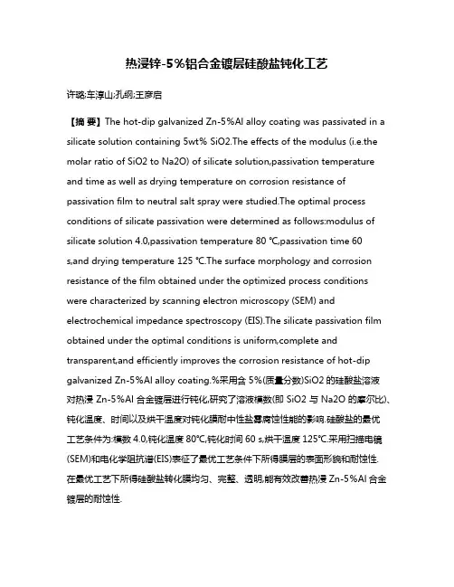
热浸锌-5%铝合金镀层硅酸盐钝化工艺许璐;车淳山;孔纲;王彦启【摘要】The hot-dip galvanized Zn-5%Al alloy coating was passivated in a silicate solution containing 5wt% SiO2.The effects of the modulus (i.e.the molar ratio of SiO2 to Na2O) of silicate solution,passivation temperature and time as well as drying temperature on corrosion resistance of passivation film to neutral salt spray were studied.The optimal process conditions of silicate passivation were determined as follows:modulus of silicate solution 4.0,passivation temperature 80 ℃,passivation time 60s,and drying temperature 125 ℃.The surface morphology and corrosion resistance of the film obtained under the optimized process conditions were characterized by scanning electron microscopy (SEM) and electrochemical impedance spectroscopy (EIS).The silicate passivation film obtained under the optimal conditions is uniform,complete and transparent,and efficiently improves the corrosion resistance of hot-dip galvanized Zn-5%Al alloy coating.%采用含5%(质量分数)SiO2的硅酸盐溶液对热浸Zn-5%Al合金镀层进行钝化,研究了溶液模数(即SiO2与Na2O的摩尔比)、钝化温度、时间以及烘干温度对钝化膜耐中性盐雾腐蚀性能的影响.硅酸盐的最优工艺条件为:模数4.0,钝化温度80℃,钝化时间60 s,烘干温度125℃.采用扫描电镜(SEM)和电化学阻抗谱(EIS)表征了最优工艺条件下所得膜层的表面形貌和耐蚀性.在最优工艺下所得硅酸盐转化膜均匀、完整、透明,能有效改善热浸Zn-5%Al合金镀层的耐蚀性.【期刊名称】《电镀与涂饰》【年(卷),期】2017(036)024【总页数】5页(P1307-1311)【关键词】锌-铝合金;热浸镀;硅酸盐;钝化;耐蚀性;表面形貌【作者】许璐;车淳山;孔纲;王彦启【作者单位】华南理工大学材料科学与工程学院,广东广州 510640;华南理工大学材料科学与工程学院,广东广州 510640;华南理工大学材料科学与工程学院,广东广州 510640;华南理工大学材料科学与工程学院,广东广州 510640【正文语种】中文【中图分类】TQ153.2;TG174.4镀锌钢因具有优异的耐蚀性而被广泛应用于机械、汽车、电力、建筑等领域。
海南医学2024年3月第35卷第6期Hainan Med J,Mar.2024,Vol.35,No.6Ⅱ型糖尿病对口腔种植体周围影响的研究进展刘彧池综述张琳林审校重庆医科大学附属永川医院口腔科,重庆402160【摘要】目前,口腔种植修复已成为缺牙或无牙颌患者修复缺失牙的一种越来越受欢迎的选择。
但全球糖尿病的发病呈上升趋势,同时由于糖尿病患者可能的微血管病理变化导致的局部免疫失常,使糖尿病患者种植体周围的抗感染能力低,影响成骨细胞及破骨细胞的功能,晚期糖基化终末产物积累,易伴发炎症而影响种植修复的成功率。
本文就Ⅱ型糖尿病对口腔种植体周围影响的研究进展做一综述。
【关键词】糖尿病;口腔种植;种植体周围炎;骨代谢;血糖控制【中图分类号】R587.1【文献标识码】A【文章编号】1003—6350(2024)06—0910—03Advances in the study of the effects of type Ⅱdiabetes mellitus on the peri-implant area of oral implants.LIU Yu-chi,ZHANG Lin-lin.Department of Stomatology,Yongchuan Hospital of Chongqing Medical University,Chongqing 402160,CHINA【Abstract 】Oral implant restoration has become an increasingly popular option for restoring missing teeth in pa-tients with edentulous or edentulous jaws.However,the incidence of diabetes mellitus is on the rise globally,and at the same time,due to the local immune malfunction caused by possible microvascular pathological changes in diabetic pa-tients,the peri-implant resistance of diabetic patients is low,which affects the function of osteoblasts and osteoclasts,and the accumulation of late glycosylation end-products,which is easily accompanied by inflammation and affects the success rate of implant prosthetics.This article provides a review of the progress of research on the effects of type Ⅱdia-betes mellitus on the peri-implant area of oral implants.【Key words 】Diabetes mellitus;Oral implants;Peri-implantitis;Bone metabolism;Glycemic control ·综述·doi:10.3969/j.issn.1003-6350.2024.06.030基金项目:2022年重庆市永川区科技局自然科学基金项目(编号:2022yc-jckx20051)。
负载三七的纳米氧化锌缓释凝胶制备方法刘宗响1,牟杰2,3△,陆建吾2,赵伯南2,徐铭递2,高干3,李程3,徐新2,彭甜甜2 (1.徐州医科大学附属徐州口腔医院,江苏徐州 221002;2.徐州医科大学药学院,江苏徐州 221004;3.江苏省新药研究与临床药学重点实验室,江苏徐州 221004)[摘要]目的制备纳米氧化锌吸附三七总皂苷的卡伯姆水凝胶。
方法考察了纳米氧化锌浓度、三七浓度对纳米胶束粒径的影响;载药纳米粒的细胞毒性和抑菌能力;不同pH值对凝胶溶胀性能及三七释放效率的影响;将卡波姆胶作为基质,分散氧化锌纳米粒及三七总皂苷后,制备新型缓释水凝胶。
结果纳米氧化锌最佳浓度为1.25 mmol/L时,三七总皂苷浓度在0.04%时,粒径最小。
纳米氧化锌含量增加,抑菌能力随之增加,浓度1 μg/mL时抑菌能力较为稳定;纳米氧化锌浓度低于2 μg/mL时,生物安全性好。
凝胶的溶胀度和三七总皂苷释放量均随溶液pH值增大而增大,在模拟体液中最峰值。
结论纳米氧化锌的含量为1 μg/mL,三七总皂苷的含量为0.0004%时,该凝胶对治疗干槽症具有较好疗效。
[关键词]三七总皂苷;纳米氧化锌;凝胶;干槽症Preparation of zinc oxide nano sustained-release gel loaded panaxnotoginseng saponinsLIU Zong-xiang1,MU Jie2,3△,LU Jian-wu2,ZHAO Bo-nan2,XU Ming-di2,GAO Gan3,LI Cheng3,XU Xin2,PENG Tian-tian2(1.The Affiliated Stomatology Hospital of Xuzhou Medical University, Xuzhou 221002, China;2.Xuzhou Medical University School of medicine, Xuzhou 221004, China; 3. Jiangsu Province Key Laboratory of New Drug Research and Clinical Pharmacy, Xuzhou221004,China)[Abstract] Objective To prepare the carbomer hydrogels containing the panax notoginseng saponins(PNS) loaded by zinc oxide nanoparticals (ZnO NPs). Methods The variation of the particle size were investigated by chaning the conecntration of ZnO NPs and PNS. The cytotoxicity and antibacterial ability of drug-loaded nanoparticles were evaluated. The effects of different pH values on the swelling properties of gels and the release efficiency of PNS were also investigated. Results The smallest particle size was obtained at the concentration of ZnO NPs at 1.25 mmol/L and PNS at 0.04%. The antibacterial ability increased with the acsending concentration of ZnO NPs and reached the peak value at 1 μg/mL. It is safe when the concentration of ZnO NPs under 2 μg/mL. The swelling degree of the gel and the release of PNS increased when pH value added and reached the peak value in the simulated body fluid. Conclusion The gel showed excellent effect on the treatment of alveolitis when the content of ZnO NPs at 1 μg/mL and PNS at 0.0004%.[Keywords] panax notoginseng saponins; zinc oxide nanoparticals;hydrogel; alveoliti资助项目:国家级高等学校大学生实践创新训练计划立项项目(201510313028;201710313082K);江苏省高等学校大学生实践创新训练计划立项项目(2010783;201510313028Z);江苏省新药研究与临床药学重点实验室主任基金(ZR-XY201403);徐州医学院药学院教育教学改革课题(0912yxyjg008; 2015-18;Xjyppzx201608);徐州市科技计划项目(KC15SH065;KC16SY152)作者简介:刘宗响,男,主任医师,副教授,研究方向:牙周炎的防治,E-mail:xzkqlzx@;牟杰,通信作者,博士,副教授,研究方向:药物合成,E-mail:mou.jie@。
重庆大学硕士学位论文缺钙纳米羟基磷灰石/胶原复合支架材料的制备姓名:帅丽申请学位级别:硕士专业:药物化学指导教师:季金苟2010-04摘要骨组织修复材料长期以来都是生物医学材料领域的热门课题。
近二十年来,由于组织工程支架材料的很多优点使得其已逐渐成为骨修复材料研究发展的方向。
支架材料的发展经历了由单一的生物高分子材料、无机生物陶瓷材料等向复合多孔支架材料发展的道路。
羟基磷灰石(HA)与有机聚合物复合的材料是当前硬组织修复材料研究中的热点之一。
HA是人骨无机结构的主要成分,具有较好的生物相容性和生物活性,能与骨组织中的其他成分形成牢固的键合,因此HA一直是骨修复和替代材料研究的主要课题。
但由于其脆性大,韧性差,在生理条件下缺乏抗疲劳性,因此限制了它的临床应用范围。
如果将HA与一些弹性和韧性较好,且成分与人骨接近的生物大分子复合,就可以将二者的优势充分结合起来,有望得到强度高、柔韧好、可塑性强、力学性能好且具有良好生物相容性和生物活性的新一代骨修复材料。
基于以上原因,本课题所采用的生物大分子为胶原,将胶原蛋白与HA进行复合,从而最大限度地发挥其各自的特点,扩大其临床应用范围。
本文以草鱼鱼鳞为原料,采用胃蛋白酶从鱼鳞中提取胶原蛋白,通过单因素实验考察不同前处理、提取介质以及不同的提取方式对胶原蛋白提取效率的影响,研究结果表明:鱼鳞胶原蛋白的最佳提取工艺为采用微波辅助去杂,以0.1mol/LHCl浸泡除钙,再以1%的柠檬酸(含1%胃蛋白酶)作为提取介质,并用超声辅助提取的方法得到的I型胶原蛋白。
把纯化后的鱼鳞胶原蛋白用以红外光谱分析,确定所提取鱼鳞胶原蛋白的特征基团。
本文以Ca(NO3)2·4H2O、(NH4)2HPO4和NH4HCO3为原料,采用化学沉淀法辅以微波辐射制备了含碳酸根的纳米缺羟基磷灰石(d-CHA)、磷酸三钙(TCP)、不含碳酸根的纳米缺钙羟基磷灰石(d-HA)、以及HA,通过共混法和共沉淀的方法制得不同类型的磷酸钙/胶原复合支架,并将其通过在模拟体液中的浸泡来考察其生物活性。
The Behavior of Fluids at Interfaces 液体在界面处的行为液体是一种特殊的物质,它具有不可压缩性和流动性。
在界面上,液体与其他物质之间的相互作用对于很多自然现象都有着决定性的影响。
本文将重点探讨液体在界面处的行为,涉及表面张力、界面扩散、界面反应等多个方面。
表面张力在液体表面形成的分子层,由于周围没有与其相互吸引的同类分子,因此会对表面产生挤压力,这种力就是表面张力。
表面张力可以用来解释很多自然现象,比如水珠会在玻璃板上滚动而不是在那里静止。
表面张力也是导致液滴成球形的原因之一。
在液体表面,表面张力形成的跨越单位长度的力被称作表面张力系数,通常表示为$\gamma$。
那么表面张力系数的值受什么因素的影响呢?其实,表面张力系数的值与分子间的相互作用力密切相关。
在相同的温度和压力下,分子间的相互作用力越强,表面张力系数也就越大。
因此,水的表面张力系数比酒精的大,而水与气体的界面上表面张力系数也比较大。
随着温度的升高,表面张力系数会逐渐减小,这是因为分子温度的增加意味着分子运动更加活跃,表面张力会随之减弱。
界面扩散当两种不同的液体相碰时,它们的边界往往不是稳定的,会发生相互扩散的现象。
这种现象称为界面扩散。
界面扩散的速度可以用一个参数来描述,叫做界面扩散系数,通常用$D$来表示。
界面扩散系数的大小取决于液体的物理性质和温度等因素。
对于相同的液体,由于温度的升高分子速度变快,因此界面扩散系数也会增加。
对于不同的液体,界面扩散系数与它们之间的相互作用力密切相关。
具有较强相互作用力的液体之间的界面扩散系数通常会更小,而弱相互作用力的液体之间则相反。
界面反应在两种液体的界面上,还可以发生化学反应,这种反应称为界面反应。
界面反应通常受到多种因素的影响,包括反应物的浓度和温度、界面面积等。
界面反应中,除了正常的反应速率外,还需要考虑物质在界面上的传递和扩散,这对于反应的速率也有着很大的影响。
MB ChB ProgrammeCourse ListCodeCourse Title Length of Study Medical Year OneUGC293Z Health and Society I1st Term (Required General Education coursefor medical students)MED1293Health and Society II2nd Term MED1100Integrated Medical Sciences2 Terms MED1200Skills Modules2 Terms MED1220Communication for Medical Students2nd Term SSM1000Selected Study Modules (SSM)2 TermsA) SSM1001 - 1100 Human Structure SSMB) SSM1101 - 1999 Topical SSM Medical Year TwoMED2293Health and Society 2nd Term MED2100Integrated Medical Sciences 2 Terms MED2200Skills Modules 2 Terms SSM2000Selected Study Modules (SSM) 2 TermsA) SSM2001 - 2300 Healthcare Database AnalysisB) SSM2301 - 2600 2-Day Journal Paper AnalysisC) SSM2601 - 2999 5-Day Journal Paper AnalysisMedical Year Three MED3293Health and SocietyYear MED3100Integrated Medical SciencesYear MED3200Skills ModulesYear SSM3000Selected Study Modules (SSM)7 weeks A) SSM3001 Medical ResearchMED3110Junior Medical Clerkship8 months MED3210Junior Surgical Clerkship8 months MED3510Combined Clinical Examination Medical Year FourMED4010Community and Family Medicine MED4110Obstetrics and Gynaecology MED4210Paediatrics 1 year MED4310Psychiatry MED4200Skills Modules SSM4000Selected Study Modules (SSM)(teaching embedded in Year 4 modules)MED4410Electives 6 weeksMED4510Combined Clinical Examination }Medical Year Five} MED5110 and 5210Senior Medical Clerkship and Senior SurgicalClerkship1 yearMED5200Skills ModulesSSM5000Selected Study Modules (SSM)Course DescriptionMedical Year OneUGC293Z/MED1293Health and Society I & IIThis course enables students to understand some of the broader concepts of health, disease and disease prevention. The objectives include: 1) to understand essential public health principles and practices; 2) to be familiar with various modes of health care delivery and financing; 3) to appreciate the importance of evidence-based health care; 4) to regard patients in their holistic setting; as members of a family and a community; 5) to establish caring attitudes; and 6) to value the importance of medical ethics and the need for clinicians to meet high ethical standards.MED1100Integrated Medical SciencesIn Medical Year One the Integrated Medical Sciences course includes six major areas of study.The Cardiovascular-Respiratory System Panel offers a series of lectures on cardiovascular histology and physiology in Year 1. These basic science topics are integrated vertically with clinical topics in Year 3.The Foundation Studies is an integrated course covering the structural, physiological and molecular basis of cell and tissue functions in the human body. This course intends to provide a solid foundation upon which the students can embark onto the system-based and more advanced areas of their medical education.The Gastroenterology and Nutrition study is to acquire basic principles and concepts of gastrointestinal physiology and to understand the pathophysiological basis of gastrointestinal diseases. The histology of the gastrointestinal tract is also studied in relationship to functions.The Homeostasis study mainly focuses on regulation of body fluid volumes, osmolarity, electrolytes, and acid-base balance by the kidney. The concept of homeostasis is introduced. The study of how body metabolism is integrated under different physiological states to maintain energy supply to cells is also covered.The Human Structure study provides students with a working knowledge and terminology of human body parts. This serves as a basis for: 1) understanding the organization and function of the body systems; 2) clinical examination and execution of procedures commonly encountered in general practice; and 3) acquiring a set of professional vocabulary to be used in communicating with fellow professionals and the layperson.The Musculo-skeletal study introduces the students to the biomedical sciences related to the musculoskeletal system and the scope of clinical problems related to injury or dysfunction of the musculoskeletal system. Students are asked to think critically and thoroughly about the composition, structure and functions of the musculoskeletal tissues, organs and their organizations.MED1200Skills ModulesThe skills course focuses on clinical methods, communication skills and life-long learning skills. The objective of this course is to develop the students to become competent doctors with appropriate knowledge, skills and attitudes to meet the challenges of our changing health care needs.During the Clinical Methods course, students learn how to solve a clinical problem using a hypothesis testing approach. It teaches students how to pose questions, perform physical examination and clinical procedures to reach a diagnosis and make a clinical decision, based on evidence and patient’s preference. Clinical examples are used to demonstrate the clinical relevance of structures and functions of various systems and their inter-dependency to maintain a healthy functional state. Students also visit different clinical departments to appreciate the multidisciplinary and interdependent nature of disease management, ranging from health promotion, prevention, and treatment to rehabilitation. Students will be taught initially in the Clinical Skills Learning Centre (CSLC) using manikins and simulated patients, followed by practice in real life situations. Throughout the course, the CSLC remains a focal point where clinical skills will be consolidated under guided teaching and continuous assessment.The component for Communication Skills is designed for students to learn and practise basic communication and presentation skills in four workshops: non-verbal communication, questioning, active listening, responding and public speaking. The course uses a smaller group format with videotaped role-play interviews, with observation and constructive feedback by tutors and classmates as the instructional format.The section for Life-long Learning Skills is designed for students to first acquire an internationally recognized standard of competency in information technology literacy. Upon completion, students are introduced to the techniques and technologies that clinicians use in the practice of evidenced based medicine (i.e. assess, ask, acquire, appraise, and apply clinical evidence to patient care). In the first year, students are required to learn how to phrase a clinical question (so that a clinical answer can be found), where to locate relevant information (so that the most appropriate medical information databases are used for different clinical queries), and how to compose effective search strategies for a variety of medical information databases (so that available evidence will be successfully located).MED1220Communication for Medical StudentsThis required English course for all Medical Year 1 students will be run in the second term. This course will focus on communication and writing skills for medical students.SSM1000Selected Study ModulesThe Selected Study Modules (SSM) is compulsory and takes up 30% of the whole medical curriculum. SSM goes beyond the limits of the core teaching and allows students to study in depth in areas of interest of their selection and aims at cultivating insights into scientific methods and encouraging self-directed study. In the first year, SSM includes selections from three different SSM sub-modules: University General Education courses, Human Structure and critical review Topical SSM.Medical Year TwoMED2293Health and SocietyThe Family Follow-up Project provides a unique opportunity for students to observe the growth of a child from birth to three years of age in a normal family environment rather than in a hospital setting. At the end of the project, students will be able to appreciate the influences of the socio-economic background of the family, the health beliefs and practices, and social support on childcare and family adjustment. This project also provides a unique opportunity for students to learn the techniques of interviewing and the development of long-term relationships with a client family.MED2100Integrated Medical SciencesIn Medical Year Two the Integrated Medical Sciences course includes eight major areas of study.The Cardiovascular-Respiratory System Panel offers two modules of studies in Year 2. The first is on respiratory histology and physiology and the second on respiratory medicine and therapeutics. These modules are integrated horizontally in this academic year.The Gastroenterology and Nutrition study provides students with the knowledge of nutrition in health promotion, disease prevention and the treatment of common gastrointestinal diseases. During this period, students will also learn the pharmacology of drugs acting on the liver and the gastrointestinal tract.The Haematology, Infection and Immunity study delivers two main consecutive modules of teaching in the second and third years of the curriculum. Contents of second year teaching include basic haematology, basic immunology, and general microbiology including bacteriology, mycology, parasitology, virology and antimicrobials.The Homeostasis study concentrates on the role of the endocrine system in maintaining a stable internal environment within the human body. Basic principles of endocrine control and functions of hormones from major endocrine glands are introduced, and these serve to form the basis for understanding the pathophysiology and therapeutic treatment of endocrine disorders.The Human Structure study provides students with a working knowledge and terminology of human body parts. This serves as a basis for: 1) understanding the organization and function of the body systems; 2) clinical examination and execution of procedures commonly encountered in general practice; and 3) acquiring a set of professional vocabulary to be used in communicating with fellow professionals and the layperson.The Mechanisms of Disease and Therapeutic Approaches study focuses on the understanding of mechanisms underlying the development and progression of disease, which discusses the logical and effective administration of therapeutic interventions or strategies. The course covers: 1) the molecular basis of disease; 2) pathological processes in tissues; 3) general principles of neoplasia; 4) pathology of injury (forensic medicine); and 5) pharmacology and therapeutics.The Musculo-skeletal study introduces the students to the biomedical sciences related to the musculoskeletal system and the scope of clinical problems related to injury or dysfunction of the musculoskeletal system. Students are asked to think critically and thoroughly about the composition, structure and functions of the musculoskeletal tissues, organs and their organizations.The Neuroscience study provides a framework on structure and function of central and peripheral nervous systems, and on clinical diagnosis and treatment of diseases related to the human nervous system. The second-year teaching focuses on the basic function and organization of the nervous tissues and their clinical relevance in pathological states.MED2200Skills ModulesThe skills course focuses on clinical methods, communication skills and life-long learning skills. The objective of this course is to develop the students to become competent doctors with appropriate knowledge, skills and attitudes to meet the challenges of our changing health care needs.During the Clinical Methods course, students learn how to solve a clinical problem using a hypothesis testing approach. It teaches students how to pose questions, perform physical examination and clinical procedures to reach a diagnosis and make a clinical decision, based on evidence and patient’s preference. Clinical examples are used to demonstrate the clinical relevance of structures and functions of various systems and their inter-dependency to maintain a healthy functional state. Students also visit different clinical departments to appreciate the multidisciplinary and interdependent nature of disease management, ranging from health promotion, prevention, treatment to rehabilitation. Students will be taught initially in the Clinical Skills Learning Centre (CSLC) using manikins and simulated patients, followed by practice in real life situations. Throughout the course, the CSLC remains a focal point where clinical skills will be consolidated under guided teaching and continuous assessment.The components for Communication Skills focuses on understanding the patient’s perspective and the patient-doctor relationship. Students will learn components why patients have come to consult their doctor and what their agenda, i.e. concerns and expectations, are. Students will learn how to develop rapport with the patient by considering the context and the impact of the illness on his/her life, family and work. A medium-sized group format with videotaped role-play interviews, observation, and constructive feedback by tutors and classmates, will be used. Students will also get an opportunity to be attached to the hospital to interview newly admitted patients and report their experience in small groups.The Life-long Learning Skills in year two continues with developing the students’skills for the practice of evidenced based medicine (i.e. the ability to assess, ask, acquire, appraise, and apply clinical evidence to patient care). Students are required to learn and apply the rules of evidence for each of four major types of clinical investigations: 1) therapy/ prevention; 2) harm/causation; 3) prognosis; and 4) diagnosis. Topical coverage is coordinated with the other two skills panels.SSM2000Selected Study ModulesIn the second year there are three different categories of Selected Study Modules, namely university general education, computer-aided database analysis project (First Term, 52 protected hours) and journal paper reviews (Second Term, 112 protected hours). In groups of six and guided by teachers, students will conduct an analysis of a healthcare or medical related database. The project enables them to learn and apply their analytical as well as statistical skills. In the critical review of journal papers, students will undertake four modules, which allows them to learn and practise the basic principles of critical analysis of published data and evidence-based approach to medicine and health information.Medical Year ThreeMED3293Health and Society (PHES3)This is an interdisciplinary course which examines the broad concepts of health and society with particular reference to the society of Hong Kong. Discussion topics include learning and memory, personality, family dynamics, behavioural determinants of health, hospitalization, death and bereavement, patient compliance and the social welfare system in Hong Kong. Students will be guided to gain insight into patients as an individual, a family member and a community member. Principles of medical ethics will also be discussed.The Family Follow-up Project provides a unique opportunity for the students to observe the growth of a child from birth to three years of age in a normal family environment rather than in hospital setting. The programme’s objectives are that, at the end of the programme, the students will be able to appreciate the influences of the socio-economic background of the family, the health beliefs and practices, and social support on child care and family adjustment. This project also provides a unique opportunity for students to learn about interviewing and the development of long-term relationships with a client family. MED3100Integrated Medical SciencesIn Medical Year Three, the Integrated Medical Sciences course includes eight major areas of study:The Cardiovascular-Respiratory System Panel offers a series of lectures on cardiovascular medicine and pharmacology in Year 3. Together with the topics on respiratory medicine and therapeutics in Year 2, they form the groundwork for students to function as junior clerks in the wards.Gastroenterology and Nutrition enables students to be familiar with nutritionally related diseases commonly encountered due to nutritional deficiency or over-nutrition and to develop the attitudes and skills in nutrition advice for disease prevention.Haematology, Infection and Immunity delivers two main consecutive modules of teaching in the second and third years of the curriculum. Contents of the year-three teaching include immune problems in transplantation, congenital or acquired immune deficiency, aging and cancers; understanding of immunotherapy, understanding of the general approach to anaemias, cytopenias/cytosis, bleeding and thrombotic disorders, and the basic concept of transfusion, working knowledge and understanding of prevention, diagnosis and management of infectious diseases caused by bacteria, viruses and parasites, understanding of how antimicrobial resistance occurs and spreads, and the understanding of the importance of judicious use of antimicrobial agents.The teaching of Homeostasis (Renal, Endocrinology and Metabolism) is divided into ten clinical sessions, each of which is in turn divided into two parts. They are mostly lecture-based and represent integrative clinical-pathological teaching involving clinical and pre-clinical departments. The first five teaching sessions are related to endocrinology/metabolism, while the remaining five are devoted to renal medicine/urology. In some cases, clinical demonstration will be used to better illustrate the effects of diseases, and to provide more opportunities for discussing the principles of diagnosis and treatment of patients.Mechanisms of Disease and Therapeutic Approaches provides a firm scientific base to understand the mechanisms of disease, and to relate these to sound therapeutic principles and measures. This course completes the year-two teaching on the General Principles of Neoplasia, and on Pharmacology and Therapeutics and concludes with a module in Forensic Medicine.In the third year curriculum in Musculo-Skeletal, common and major clinical problems in orthopaedics and traumatology are introduced with the aim to highlight their uniqueness in clinical practice. Basic principles of clinical practice in musculoskeletal problems will be emphasized with the aims to prepare the students for their clinical modules in the Years Four and Five. Integrated approaches will be highlighted throughout the teaching programme.Neuroscience in Year Three provides students with the clinical skills to assess a patient with a neurological disorder by means of history and examination. Students will learn to adopt a multidisciplinary team approach to assessment and treatment of some neurological disorders, particularly those causing long term disabilities. The main teaching on neurological examination will take place during the Function Module. Students will be doing neurology, neurosurgery and rehabilitation for one week each.Reproduction, Sex, Human Development and Growth (PREP3) provides a detailed knowledge of reproduction and those aspects of the early and later stages of embryonic development relevant to the reproductive system and to the management of normal and abnormal pregnancy and childbirth. Students will gain an understanding of the pathological processes which may affect reproduction, pharmacology of reproduction and the special requirements of prescribing in the young and in the elderly. The principles of genetics applied to clinical problems and the principles of the biological processes of ageing, and their relevance to the management of diseases in the elderly will be included. The course will bring an awareness of the importance of social, ethical and legal issues surrounding reproduction, development and ageing.MED3200Skills ModulesClinical Methods (PCLM3)Based on the learning experience in PCLM1 and PCLM2 and in collaboration with Communication Module and Clinical Module, Clinical Methods aims to further consolidate students’ ability to use history taking and physical examination to gather relevant clinical information to create problem lists and differential diagnoses.Student’s skills in case presentation and discussion will be strengthened through practice and feedback in small groups and under guidance. The Clinical Skills Learning Centre (CSLC) will be used as a resource centre to clarify inconsistencies and queries relating to clinical methods which may be encountered by students during their clinical attachments in different hospitals and clinics.Communication Skills (COSK3)Students will learn how to apply the skills learnt in COSK 1 and COSK 2 in obtaining a relevant clinical history. Furthermore, students will be taught the following skills: Ability to listen and observe the verbal and nonverbal messages from the patients Ability to take a clinical history and look after the patient’s and the doctor’s agenda Ability to handle the feelings and emotions of the patients during history takingAbility to share the understanding with the patient during the process of history taking. The Life Long Learning Skills (LLSK3)In this third year of the medical programme, the nature of coverage in Life Long Learning Skills focuses initially on learning additional evidence-based medicine (EBM) review criteria, specifically those for critiquing published systematic reviews. Six hours of relevant instruction and workshops in critiquing relevant published systematic reviews are scheduled. Students’summative assessments are based on critiquing relevant articles via small group assignments.Subsequently students will begin to learn the life long process of how to clinically judge if and when published clinical research findings (pertaining to therapeutic interventions, harm exposures, diagnostic tests, and/or prognostic indicators) can or should be incorporated into or considered directly relevant to the clinical care of one’s patients. Seven hours of these latter EBM practice sessions will be provided during each rotation in Medicine and Surgery.Students will be given purposefully designed EBM assignments and be required to make oral presentations to their peers and supervising clinical teachers as to if relevant research exists and if so whether the findings should meaningfully inform the clinical care of selected patients they have seen during ward rounds in Medicine and in Surgery. These presentations also provide a modality of continuous, formative assessment and are designed to develop the student’s clinical decision making abilities within a clinical practice context of clinical practice that is appropriately informed by clinical research.SSM3000Selected Study Modules (SSM)SSM3001Medical ResearchIn Medical Year three, students will have to undertake a “Medical Research SSM”. After the first and second years, it is generally believed that third year students will have developed their ability to independently pursue areas of interest and research. With further guidance, students should be reasonably capable of carrying out some simple research work by themselves. The aim of the “Medical Research SSM” is to provide an experiential opportunity for students to progress in this area. Furthermore, for potential students, it may also pave the way for them to take a one-year Intercalated Degree Programme in Medical Sciences.The “Medical Research SSM” of the third year, as compared with the first and second years SSM, will be a much longer and more in-depth project. Over a dedicated period of seven full weeks in the Medical Year three curriculum, this research-oriented project will be a single study, either in laboratory science or clinical medicine. With contributions from different teaching departments, the “Medical Research SSM” provides a multidisciplinary perspective to the programme as a whole and in addition, caters for the particular interest of individual students. Free choice of research areas will enable students to explore critically and master comprehensively, subjects and disciplines that excite their curiosity.MED3110/MED3210Junior Medical Clerkship/Junior Surgical ClerkshipStudents will be allocated to medical and surgical wards in various hospitals and will be taught to take histories and examine patients on a daily basis and subsequently to present their findings to their colleagues and their clinical teachers. They would also learn how to manage patients with different medical or surgical problems. In the surgical rotations, they would also have the opportunity to observe and participate in operative procedures in the operating theatres.MED3510Combined Clinical ExaminationAt the end of the year, students will be assessed on their clinical clerkships through a Combined Clinical Examination which constitutes part of their Second Professional Examination. Medical Year FourStudents will rotate through four Clinical Modules. During each rotation students will undertake four Department-based Selected Study Modules (SSM) and at the end of the year each student will select and organize an elective (these SSM and elective activities account for 30% of the course). To proceed to Year 5 students are required to pass each of the four Clinical Module examinations as well as the Combined Clinical Examination.SSM4000The SSM programme in the 4th medical year is designed to provide students with an opportunity to gain an in-depth understanding of a clinical problem or area of healthcare services delivery of the four specialties, namely Community and Family Medicine, Obstetrics and Gynaecology, Paediatrics and Psychiatry. The four specialized SSM projects are to consolidate the students’ knowledge, skills and research ability through studying a specific topic.In Medical Year 4, the SSM programme will be embedded in the four rotation modules. However, participation of teachers from other departments in the delivery of the SSM, where appropriate, is encouraged. Students will be required to do four different SSM projects, one in each of the specialties. In a 10-week module, they will spend approximately 1.5 weeks in the SSM.To allow creativity and flexibility in the SSM, there will be no prescribed formats for the department-based exercises. However, the title, educational objectives, operational details and deliverables of all SSMs require documentation and prior approval by the SSM Committee.Assessment of all SSM comprises 2 parts; a written report of the SSM and an oral presentation to their peers in the module.Students must pass all SSM assessment to be eligible for promotion to Year 5.MED4010Community and Family MedicineThis course provides ten weeks of integrated teaching in Community Medicine and Family Medicine.In Community Medicine, two major areas are covered: Epidemiology & Public Health Practice and Occupational & Environmental Medicine. Students will be introduced to the major causes of morbidity and mortality in Hong Kong and the prevention and control of communicable and non-communicable diseases. In addition to didactic lectures, students will learn the subject areas through active participation in problem-solving exercises, field visits and presentations in seminars and tutorials.The clinical clerkship in Family Medicine aims at teaching the students to understand how medical conditions and health problems are presented in community settings. Throughout the clerkship, the students will be taught on basic principles and practice of family medicine in providing primary, comprehensive, whole person and continuing care. The common health problems in the community including skills in management will also be covered by lectures, seminars, tutorials, clinical attachment or self directed learning packages. The range of teaching methods also include video-taping, clinical interviews and clinical role-playing. There is clinical teaching at the University Family Medicine Clinics and Teaching Units (in the Lek Y uen Health Centre, Prince of Wales Hospital Family Medicine Training Centre, Kwong Wah Hospital Family Medicine Training Centre), and also to Family Medicine clinics run by private practitioners and institutions both public and private settings. Continuity of care and communication skills are emphasized in the context of the family and the community, together with the principles of the assessment and management of problems presenting at early stage in undifferentiated way.In the Selective Study Module (SSM), students will have the opportunity to gain deeper insight to selected problems in family medicine and public health.The students are assessed on the theory and practice of Community Medicine and Family Medicine in a clinical context.MED4110Obstetrics and GynaecologyWithin this 10-week module, students will undergo 4 clinical rotations which are mainly based at the Prince of Wales Hospital: 1) antenatal clinic and ward; 2) gynaecology clinic and ward; 3) labour ward; and 4) O&G services in affiliated hospitals. Core materials will be covered in lectures and formal tutorials, supplemented by bedside teaching.During their antenatal attachment, students will gain understanding of normal pregnancy, of the growth and development of the unborn child, and will acquire competency in performing obstetrics examinations.。
*Corresponding author.Tel.:#34-93-402-1134;fax:#34-93-402-1138.E-mail address:lcleries @fao.ub.es (L.Cleries).Biomaterials 21(2000)1861}1865Behavior in simulated body #uid of calcium phosphate coatingsobtained by laser ablationL.Cle ries *,J.M.Ferna ndez-Pradas,J.L.MorenzaDepartament de F n &sica Aplicada i O "ptica,Uni v ersitat de Barcelona,A v da.Diagonal 647,E-08028Barcelona,SpainReceived 28July 1999;accepted 20February 2000AbstractThree types of calcium phosphate coatings onto titanium alloy substrates,deposited by the laser ablation technique,were immersedin a simulated body #uid in order to determine their behavior in conditions similar to the human blood plasma.Neither the hydroxyapatite coating nor the amorphous calcium phosphate coating do dissolve and the -tricalcium phosphate phase of the coating of -tricalcium phosphate with minor phase slightly dissolves.Precipitation of an apatitic phase is favored onto the hydroxyapatite coating and onto the coating of -tricalcium phosphate with minor phase.Onto the titanium alloy substrate reference there is also precipitation but at larger induction times.However,onto the amorphous calcium phosphate coating no precipitate is formed. 2000Elsevier Science Ltd.All rights reserved.Keywords:Calcium phosphate;HA;Pulsed laser deposition;SBF1.IntroductionLaser ablation is a technique employed for the depo-sition of calcium phosphate coatings onto metallic substrates that will be used as implants for bone recon-struction.With this technique,calcium phosphate coatings with tailored phases and structures have suc-cessfully been produced [1,2]and their dissolution properties in undersaturated conditions have been assessed [3,4].However,the real body #uid conditions are saturated with respect to the hydroxyapatite phase,that is,the concentration of calcium ions is higher than the one in equilibrium with this phase.Consequently,it is interest-ing to also test the calcium phosphate coatings in condi-tions closer to the in vivo situation,in order to know their integrity in these conditions and the catalytic }react-ive properties of their surfaces towards precipitation pro-cesses.Therefore,amorphous calcium phosphate coatings (ACP),hydroxyapatite coatings (HA),and coatings of -tricalcium phosphate with minor phase ( -TCP)deposited by laser ablation were immersed in a saturatedsolution for di !erent time periods and the evolution oftheir constitutive properties was determined.The saturated solution used was the simulated body #uid (SBF),a solution whose ion concentrations and pH are almost equal to those of human blood plasma [5].This solution is also the one utilized in the biomimetic (pre-cipitation)process for the production of apatite layers onto the sol }gel activated titanium substrates [6].2.ExperimentalThe simulated body #uid [5]was prepared by dissolv-ing reagent grade chemicals strictly in the following or-der:NaCl,NaHCO ,KCl,K HPO )3H O,MgCl)6H O,CaCl )2H O,and Na SOinto deionized water.The #uid was bu !ered at pH "7.4at 373C with tris-hydroxymethyl-aminomethane and hydrochloric acid.The inorganic composition of SBF emulates that of human blood plasma,as shown in Table 1.No precipita-tion was observed during #uid preparation.Coatings of HA, -TCP,and ACP deposited onto titanium alloy (Ti }6Al }4V)substrates by laser ablation of HA with an excimer laser at 248nm and bare titanium alloy substrates degreased in ultrasonic baths with triclorethylene,acetone and ethanol,were used.Details on the preparation and characterization of the coatings0142-9612/00/$-see front matter 2000Elsevier Science Ltd.All rights reserved.PII:S 0142-9612(00)00060-0Table 1Milimolar concentrations (m M )of the ions of the SBF solution and comparison to those of human plasma [5]Na >K >Ca >Mg >Cl \HCO \HPO \SO \ SBF142.0 5.0 2.5 1.5147.8 4.2 1.00.5Human plasma142.05.02.51.5103.027.01.00.5Bu !er (TRIS solution):tris-hydroxymethyl-aminomethane (CH OH) CNH50m M #HCl 45m M.Fig.1.Scanning electron micrographs for (a)the HA coating,(b)the -TCP coating,(c)the ACP coating,after 8days immersion,and (d)the titaniumalloy substrate after 28days immersion.selected for this study,can be found in previous papers [1}4].All the coatings had a thickness around 1 m.Each sample,with an area of 1cm ,was soaked in 24ml of the SBF solution into separate stopped vials at 373C in a thermostatic oven,for di !erent periods:1,4,8,and 28days.At that point,each representative sample was care-fully washed with distilled water,air dried,weighted and characterized by X-ray di !raction,Raman spectroscopy and scanning electron microscopy (SEM).3.Results 3.1.HA coatingThe SEM micrograph after 8days immersion,depicted in Fig.1a,shows that over the columnar coating struc-ture,a quite dense precipitated layer appears.This layer is not strongly adhered to the underlying HA coating since it cleanly detaches from the HA coating in certain1862L.Cle %ries et al./Biomaterials 21(2000)1861}1865Fig.2.X-ray di !raction spectra for (a)the HA coating,(b)the -TCP coating,(c)the ACP coating,before and after 8days immersion,and (d)the titanium alloy substrate before and after 28days immersion.areas,underexposing the original HA surface which doesnot seem to have degraded.The X-ray di !raction spectra before and after 8days in SBF are shown in Fig.2a.The initial spectrum contains,apart from the substrate peaks,only HA peaks that do not diminish after 8days in solution.It is distinguishable at day 8that the apparition of a broad band centered around 323superimposed to the HA peaks,with an additional peak at 25.93,which are attributed to a non-well crystallized apatite [7]with a preferred (002)orientation.A representative Raman spectrum after 8days (Fig.3a)shows the 962cm \ peak of the HA coating and a relatively small,almost indis-tinct,shoulder towards lower wavenumbers that is also attributable to a non-well crystallized apatite structure [8].The gains in mass of the coating-substrate system,tabulated in Table 2,indicate the growth of the precipi-tate with time.3.2. -TCP coatingThe SEM micrograph in Fig.1b shows that there is the formation of a thick precipitate at day 8.There are some parts where this precipitate has detached,underexposing the coating surface,which does not seem to be thatdegraded.The X-ray di !raction peaks attributed to the minor -TCP slightly diminish after immersion and those of -TCP do not change (Fig.2b).Additionally,the broad band centered around 32and the 25.93peak,attributed to a non-well crystallized apatite structure with a preferred (002)orientation,appear.The represen-tative "nal Raman spectrum (Fig.3b)shows a broad band that contains the TCP peaks at 947and 972cm \ ,but the existence of an intermediate peak at around 960cm \ suggests also the presence of a non-well crystallized apatite structure.The mass changes for the 4and 8day period,which are also tabulated in Table 2,are similar,indicating the early saturation of the precipi-tation process.3.3.ACP coatingIn the SEM image (Fig.1c)no substantial change is detected,neither dissolution nor precipitation,since the original morphology with droplets is maintained.The ACP coating does not show any X-ray di !raction peak other than the substrate ones after 8days immersion (Fig.2c).The representative "nal Raman spectrum (Fig.3c)has only a broad band which is centered towardsL.Cle %ries et al./Biomaterials 21(2000)1861}18651863Fig.3.Raman spectra for(a)the HA coating,(b)the -TCP coating, (c)the ACP coating,after8days immersion,and(d)the titanium alloy substrate after28days immersion.Table2Mass variations in mg/cm and changes observed with the character-ization techniques1day4days8days28days SEM XRDHA0.41Ppte No1.11Ppte NCA-TCP 1.17Ppte NCA#1.19Ppte NCA# ACP!0.03No No!0.03No No!0.01No No Titanium0.23Ppte*alloy0.85Ppte NCANo:non-detected change;NCA:non-well crystallized apatite struc-ture; :decrease in -TCP content;Ppte:precipitate observed.950cm\ ,characteristic of an amorphous structure[6]. Table2con"rms that there is no uptake or loss of mass.3.4.Bare titanium alloy substrateThe SEM image shows the precipitate found after28 days(Fig.1d).The X-ray di!raction spectrum(Fig.2d) indicates that it has also a non well crystallized apatite structure with a(002)preferred orientation.A broad band centered towards960cm\ in its representative "nal Raman spectrum(Fig.3d)also suggests that the precipitate has a non well crystallized apatite structure. Table2shows the mass uptake for this sample.4.DiscussionIn a previous study[3]the same type of calciumphosphate coatings used in the present work were testedin Ca-free undersaturated conditions,and it was foundthat the HA coatings were stable,that the -TCP phasein the -TCP coatings completely dissolved leavinga microporous coating and that the ACP coatings com-pletely dissolved.In the saturated conditions of the SBF neither the HA orthe -TCP phase of the -TCP coatings do dissolve andon both coatings a precipitate is found.The fact that thesephases do not dissolve is not an unexpected result if we takeinto account that this solution is saturated for the di!erentcalcium phosphates,with di!erent degrees of supersatura-tion represented by di!erent negative Gibbs free energies(for instance,!7.94kJ/mol for HA and!3.72kJ/mol for -TCP[9]).The precipitate that is formed has a non-well crystallized apatite structure with a(002)preferred orienta-tion.Indeed,apatite is the most thermodinamically favoredphase to precipitate(has the highest negative Gibbs freeenergy value),and the preferred(002)orientation isa common"nding among other studies[10,11].We have found that the precipitation rate is in theorder -TCP'HA'Ti'ACP.The precipitate isthen formed faster onto the -TCP coating than ontothe HA coating.Radin et al.[12]reported that in a SBFsolution the -TCP phase dissolved during an inductiontime before precipitation took place and suggested that itwas this initial phase dissolution leading to supersatura-tion that consequently helped precipitation.Weng et al.[13]have also suggested that the HA crystalline struc-ture is not critical in the nucleation process.Followingthese interpretations,the dissolution of the -TCP phaseof the -TCP coating could favor the precipitation ofthe non-well crystallized apatite phase on this coatingwhile for the HA coating the absence of dissolutionwould delay this precipitation.Onto the bare titanium alloy the precipitation of thenon-well crystallized apatite phase is observed althoughthe induction time towards precipitation is larger thanfor the HA coating,and is similar to those reported in theliterature[14].Ducheyne et al.[15]have also reportedthat precipitation in a SBF solution occurs earlier ontoHA than onto titanium disks.Taking into account thatneither the HA coating not the titanium alloy do releaseinto the solution the calcium or phosphate ions[3,4]thatcould help precipitation,this would suggest that in thiscase the crystalline structure is indeed important in dic-tating the di!erences in the rate of nucleation.Remarkably,there is no dissolution of the ACP coat-ing nor precipitation processes onto its surface.Contra-dictory reports have been found regarding the behaviorin a SBF solution of ACP coatings obtained by RFmagnetron sputtering:Wolke et al.[16]reported thatthese ACP coatings during immersion were maintained1864L.Cle%ries et al./Biomaterials21(2000)1861}1865and in some areas a calcium phosphate precipitate was found.However,Yoshinari et al.[17]observed dissolu-tion of ACP coated disks within one day without precipi-tation of a calcium phosphate phase.They attributed this di!erence in precipitation processes to the variations on the ratio of solution volume to sample area,the Ca/P ratio,the grain size of the coating,and the impurities.The absence of dissolution for our ACP coating could be explained on the basis that the SBF solution could be saturated with respect to this particular ACP phase.This degree of saturation cannot be easily calculated for amorphous calcium phosphate phases since it largely depends on their Ca/P ratio which can#uctuate.There is no precipitation onto the ACP coating even when onto the titanium alloy substrate a precipitate is found.This is quite surprising since,in the absence of dissolution,the ACP coating should provide a better substrate for the nucleation of apatite compared to the titanium alloy substrate since it already has calcium and phosphate ions in its structure.Therefore,other factors intervening in the mechanisms of the formation of this precipitate,apart from the existence of a calcium phosphate surface or calcium and phosphate release,should be considered.5.ConclusionThe HA coating deposited by excimer laser ablation con"rms its stability in saturated conditions towards dissolution.The ACP coating and the -TCP phase of the -TCP coating are also stable under these condi-tions.The HA and -TCP coatings favor earlier the precipitation of an apatitic phase with a(002)preferred orientation.Onto the titanium alloy substrate reference there is also precipitation but at larger induction times. However,onto the amorphous calcium phosphate coat-ing no precipitate is formed.AcknowledgementsThis work is part of a research program"nanced by DGESIC of the Spanish Government(Project MAT98-0334-C02-01)and DGR of the Catalan Government. References[1]Ferna ndez-Pradas JM,Cle ries L,Sardin G,Morenza JL.Depos-ition of hydroxyapatite thin"lms by excimer laser ablation.Thin Solid Films1998;317:393}6.[2]Ferna ndez-Pradas JM,Cle ries L,Sardin G,Morenza JL,Hydroxyapatite coatings grown by pulsed laser deposition with a beam of355nm wavelength.J Mater Res1999;14: 4715}9.[3]Cle ries L,Ferna ndez-Pradas JM,Sardin G,Morenza JL.Dissolu-tion behaviour of calcium phosphate coatings obtained by laser ablation.Biomaterials1998;19:1483}7.[4]Cle ries L,Ferna ndez-Pradas JM,Sardin G,Morenza JL.Ap-plication of dissolution experiments to characterise the structure of pulsed laser-deposited calcium phosphate coatings.Bio-materials1999;20:1401}5.[5]Kokubo T,Kushitani H,Sakka S,Kitsugi T,Yamamuro T.Solutions able to reproduce in vivo surface changes in bioactive glass-ceramic A-W .Biomed Mater Res1990;24:721}4.[6]Tanahashi M,Kokubo T,Nakamura T,Katsura Y,Nagano M.Ultrastructural study of an apatite layer formed by a biomimetic process and its bonding to bone.Biomaterials1996;17: 47}51.[7]Tong W,Wang Z,Zhang X,Yang A,Feng J,Cao Y,et al.Studieson the di!usion maximum in X-ray di!raction patterns of plasma-sprayed hydroxyapatite coatings.J Biomed Mater Res 1998;40:407}13.[8]Weinlaender M,Beumer III J,Kenney EB,Moy PK,Adar F.Raman microprobe investigation of the calcium phosphate phases of three commercially available plasma-#ame-sprayed hy-droxyapatite-coated dental implants1.J Mater Sci:Mater Med 1992;3:397}401.[9]Ishikawa K,Takagi S,Chow LC,Ishikawa Y,Eanes ED,AsaokaK.Behavior of a calcium phosphate cement in simulated blood plasma in vitro.Dent Mater1994;10:26}32.[10]Ban S,Maruno S,Iwata H,Itoh H.Calcium phosphate precipita-tion on the surface of HA-G-Ti composite under physiologic conditions.J Biomed Mater Res1994;28:65}71.[11]Wen HB,Wolke JGC,de Wijn JR,Liu Q,Cui FZ,de Groot K.Fast precipitation of calcium phosphate layers on titanium induced by simple chemical treatments.Biomaterials1997;18:1471}8. [12]Radin SR,Ducheyne P.The e!ect of calcium phosphate ceramiccomposition and structure on in vitro behavior.II.Precipitation.J Biomed Mater Res1993;27:35}45.[13]Weng J,Liu Q,Wolke JGC,Zhang X,de Groot K.Formationand characteristics of the apatite layer on plasma-sprayed hy-droxyapatite coatings in simulated body-#uid.Biomaterials 1997;18:1027}35.[14]Kim HM,Miyaji F,Kokubo T,Nakamura T.Preparation ofbioactive Ti and its alloy via simple chemical surface treatment.J Biomed Mater Res1996;32:409}17.[15]Ducheyne P,Radin R,Ishikawa K.The rate of calcium phosphateprecipitation on metal and ceramics,and the relationship to bioactivity.In:Ducheyne P,Kokubo T,van Blitterswijk CA, editors.Bone-bonding biomaterials.Leiderdorp:Reed Healthcare Communications,1992.p.213}8.[16]Wolke JGC,van der Waerden JPCM,de Groot K,Jansen JA.Stability of radiofrequency magnetron sputtered calcium phos-phate coatings under cyclically loaded conditions.Biomaterials 1997;18:483}8.[17]Yoshinari M,Hayakawa T,Wolke JGC,Nemoto K,Jansen JA.In#uence of rapid heating with infrared radiation on RF magnet-ron-sputtered calcium-phosphate coatings.J Biomed Mater Res 1997;37:60}7.L.Cle%ries et al./Biomaterials21(2000)1861}18651865。