FPGA的等精度数字频率计的设计相关中英对照外文文献翻译毕业设计论文高质量人工翻译原文带出处5
- 格式:doc
- 大小:51.51 KB
- 文档页数:13
一、课程设计原理1、测频原理及误差分析本次课程设计采用直接测频法。
直接测频法就是在确定的闸门时间内,记录被测信号的脉冲个数。
这种方法的计数值也会产生最大为±1个脉冲误差。
进一步分析测量准确度。
设待测信号脉冲周期为T1,频率为F1,当闸门时间为T=1s 时,测量准确度为&=T1/T=1/F1。
由此可知直接测频法的测量准确度与信号的频率有关。
当待测信号频率较高时,测量准确度也较高,反之测量准确度也较低。
2、占空比测量原理占空比:占空比是指高电平在一个周期之内所占的时间比率。
方波的占空比为50%,占空比为0.5,说明正电平所占时间为0.5个周期。
在1S的闸门时间之内,只要我们利用50Mhz的时钟脉冲,对待测信号的高电平时间进行计数,得到一个num值。
最后num*20ns就是所求信号的占空比了。
二、系统的设计1、分频模块分频模块我们采用50Mhz的时钟频率产生待测的信号,和三个控制信号。
此程序要求将50Mhz分出1Mhz的频率,再产生1hz作为控制信号的标准输入时钟。
该模块产生的3个控制信号,分别为EN,LOAD,CLR。
CLR信号用于在每次测量开始时,对计数器进行复位,以清除上次测量的结果,该复位信号高电平有效。
EN为计数允许信号,在EN信号的上升沿时刻计数模块开始对输入信号的频率进行测量,在此1S时间里被测信号的脉冲数进行计数,即为信号的频率。
然后将值锁存,并送到数码管显示出来。
设置锁存器的好处是使显示的数据稳定,不会由于周期性的清零信号而不断闪烁。
在每一次测量开始时,都必须重新对计数器清0。
另外,也设计出另外一个进程process,产生同样地三个控制信号给占空比测量时提供使能,锁存和清零的能力。
部分程序如下:process(clk)beginif clk'event and clk = '1' thentemp1<=temp1+1;end if;end process;freq<=temp1(16); --381Hz=50Mhz/2^172、计数模块计数模块分为2个子模块。
淮阴师范学院毕业设计物理系电子信息科学与技术专业课题名称数字频率计的设计学生姓名学生班级指导老师起讫日期 2004 .12 .1 — 2005 .4 .72005年4月7日摘要:利用等精度测量原理实现了频率的测量。
并介绍了一种进行等精度数字测量频率的硬件实现方案。
该方法简单实用,具有较广的使用价值。
关键词:数字频率计;函数信号发生器;闸门时间Abstract: A digital frequency meter designed by using equal precision measurement, have realized the frequency measurement. It introduces the hardware construction method of equal precision digital measurement frequency. This method is easy and convenient.Keywords: Digital frequency meter; Function signal generator;The interval between the opening and closing of the lock gate目录1 引言 (3)2 设计原理 (4)3 电路分析 (4)3.1 整体电路分析 (4)3.2 单元电路分析 (5)3.2.1 逻辑控制电路 (5)3.2.2 计数器 (7)3.2.3 锁存器 (8)3.2.4 BCD码七段显示译码/驱动器 (9)3.2.5 脉冲形成电路 (10)3.2.6 闸门电路 (12)3.3 整体电路图 (13)4 硬件调试 (15)4.1调试方法与过程 (15)4.1.1脉冲形成电路的调试 (15)4.1.2 时基电路的调试 (15)4.1.3锁存信号电路的调试 (15)4.1.4整体电路的调试 (15)4.2测试仪器与设备 (15)5 测试结果 (15)6心得体会 (15)7 感谢 (16)参考文献 (17)1.引言随着无线电技术的发展与普及,“频率”已成为广大群众所熟悉的物理量。
唐山学院毕业设计设计题目:基于FPGA的数字频率计设计与实现系别:信息工程系班级:10应用电子技术(1)班*名:******师:***2013年6月10 日基于FPGA的数字频率计设计与实现摘要在电子设计领域,随着计算机技术、大规模集成电路技术、EDA(Electronics Design Automation)技术的发展和可编程逻辑器件的广泛应用,传统的自下而上的数字电路设计方法、工具、器件已远远落后于当今技术的发展。
基于EDA技术和硬件描述语言的自上而下的设计技术正在承担起越来越多的数字系统设计任务。
本课题的数字频率计设计,采用自上向下的设计方法。
本文首先综述了EDA 技术的概况,接着介绍硬件描述语言VHDL,可编程器件FPGA及频率测量的一般原理;然后介绍数字频率计的系统设计,频率计各系统模块的VHDL语言实现,最后利用QUARTUS Ⅱ集成开发环境进行编辑、综合、波形仿真,并下载到CPLD器件中,经实际电路测试,仿真和实验结果表明,此频率计具有较高的实用性和可靠性。
关键字:EDA FPGA 数字频率计VHDL语言Design and Implementation ofDigital Frequency Meter Based on FPGAAbstractIn the field of electronic design, with the development of computer technology, LSI technology, EDA (Electronics Design Automation)technology and wide application of programmable logic devices, the traditional bottom-up digital circuit design methods, tools, devices have far behind today's technology. The top-down design techniques based on EDA technology and hardware description language are taking on more and more digital system design task.The topic digital frequency meter design uses top-down design approach. First, this paper summarizes the overview of EDA technology, then it describes the hardware description language which is called VHDL, FPGA programmable device and the general principles of frequency measurement; then it introduces the system design of digital frequency meter, and the realization of frequency meter each system module VHDL. Finally using QUARTUSⅡ integrated development environment edits, synthesizes, and simulates, and download to the CPLD devices, by using the actual circuit testing, simulation and experimental results show that this frequency meter is high availability and reliability.Keywords:EDA; FPGA;digital frequency meter;VHDL language目录1 引言 (1)2 硬件描述语言(HDL) (2)2.1VHDL语言简介 (2)2.2 利用VHDL语言开发的优缺点 (3)3 电子设计自动化(EDA)发展概述 (4)3.1 EDA的简介 (4)3.2 EDA的发展史 (4)3.3基于EDA的FPGA/CPLD开发 (5)3.3.1 FPGA/CPLD的简介 (6)3.3.2 用FPGA/CPLD进行开发的优缺点 (7)4 频率计的测量及方案选择 (9)4.1 数字频率计工作原理概述 (9)4.2 测频原理及误差分析 (10)4.2.1常用测频方案 (10)4.2.2 等精度测频原理 (10)4.2.3误差分析 (11)5 数字频率计的系统设计与功能仿真 (13)5.1 系统的总体设计 (13)5.2 频率计模块 (14)5.2.1 测频控制模块 (14)5.2.2 锁存器模块 (15)5.2.3 十进制计数器模块 (16)5.3 显示模块 (17)5.3.1显示模块设计 (17)5.3.2译码器模块 (18)5.3.3四位二进制数与十六位二进制数转换的源程序 (19)5.3.4十六位二进制数与四位二进制数转换的源程序 (19)5.3.5四位二进制数与段码转换的源程序 (21)6 整形电路设计 (22)6.1 555定时器的工作原理 (22)6.2 施密特触发器 (23)6.2.1 电路结构 (23)6.2.2 工作原理 (23)6.3波形的整形 (24)7 软件测试及硬件下载 (25)7.1 QuartusII软件简介 (25)7.2 QuartusII的设计流程 (25)7.3 QuartusII软件的使用方法 (26)7.3.1 创建底层模块 (26)7.3.2 构建顶层模块 (30)7.4 下载及硬件实现 (32)8 结论 (34)谢辞 (35)参考文献 (36)附录Ⅰ频率计顶层文件 (38)附录Ⅱ源程序 (39)1引言21世纪人类将全面进入信息化社会,对微电子信息技术和微电子VLSI基础技术将不断提出更高的发展要求,微电子技术仍将继续是21世纪若干年代中最为重要的和最有活力的高科技领域之一。
本科生毕业论文题目:基于fpga的等精度数字频率计的设计摘要在电子工程,资源勘探,仪器仪表等相关应用中,频率计是工程技术人员必不可少的测量工具。
频率测量也是电子测量技术中最基本最常见的测量之一。
不少物理量的测量,如转速、振动频率等的测量都涉及到或可以转化为频率的测量。
基于传统测频原理的频率计的测量精度会随被测信号频率的下降而降低。
本文介绍了一种基于FPGA的等精度数字频率计,它不但具有较高的测量精度,而且在整个测量区域能保持恒定的测量精度。
文章首先介绍了硬件描述语言(HDL)的发展,以VHDL为核心,说明了利用VHDL语言进行设计的步骤。
然后介绍FPGA器件的基本结构和开发流程,接着阐述等精度数字频率计的工作原理以及利用VHDL语言实现数字频率计的具体做法,重点是利用BCD码减法实现的BCD码除法器的设计,最后还利用modelsim软件对其进行了仿真,具体分析验证了此设计的正确性。
关键词:FPGA VHDL 等精度BCD码除法AbstractCymometer is a necessary measure tool for technical engineers in electronic engineering , resource exploration and apparatus using . frequency mesure is one of the most essential and the most common mesure of electronic mesure technology . many physical quantities’ mesure , such as rotate speed , vibration frequency’s mesure , is related with or can be transformed into frequency mesure.The precision of cymometer based on traditional frequency-testing theory will decrese when the measured frequency becomes lower. this article introduces a cymometer of same-precision based on FPGA. The cymometer not only has high precision, but also its precision doesn’t decrese when the measured frequency becomes lower.This article first introduces the development of HDL , focusing on VHDL , present the step of design of VHDL . then it introduces the basic structure and the develop flow of FPGA device . in the end , it introduces the theory of cymometer and the specific implement of cymometer based on VHDL , emphasizing the theory of implementing BCD division. the function simulation and logic synthesis also come out, showing the correction of the design .Keywords: FPGA VHDL same-precision BCD division目录第一章前言............................................................................................................... 错误!未定义书签。
基于FPGA 的数字频率计的设计2004级电子信息工程专业 何亚军 指导教师 曾技摘要 随着数字电子技术的发展,频率测量成为一项越来越普遍的工作,在电子工程、资源勘探等相关应用上,频率计是工程技术人员必不可少的测量工具。
因此,测频原理及方法的研究正受到越来越多的关注。
目前许多高精度的数字频率计都采用单片机加上外部的高速计数器来实现。
但难以提高计数器的工作频率,而且测量的精度不高。
因此采用可编程逻辑器件(FPGA)来实现数字频率计。
应用VHDL 进行自顶向下的设计,即使用VHDL 模型在所有综合级别上对硬件设计进行说明、建模和仿真测试。
通过逻辑综合后,把适配生成的配置文件,通过编程器向FPGA\CPLD 进行下载。
最后进行硬件调试与验证。
本设计的系统除了脉冲整形、显示部分的电路不在可编程电路之中,其余的电路都集成在可编程逻辑器件中。
本设计具有测频范围宽、精度高、可靠性高等优点。
符合现代EDA 设计的要求。
关键词 频率,可编程逻辑器件,电子设计自动化,硬件描述语言1 绪论在电子技术领域内,频率与电压一样,也是一个基本参数。
随着现代科技的发展,时间及频率计量的意义已日益明显。
例如,在卫星发射、导弹跟踪、飞机导航、潜艇定位、大地测量、天文观测、邮电通信、广播电视、交通运输、科学研究、生产及生活等各个方面,都需要对时间及频率的计量,也都离不开对时间及频率的计量。
因此,测频原理及方法的研究正受到越来越多的关注。
目前多用电子计数器测频,它具有测量精度高、速度快、自动化程度高、操作简便、直接显示数字等特点,尤其是与微处理器相结合,实现了程控化和智能化,构成智能化计数器。
目前,电子计数器几乎取代了模拟式测量仪器。
而电子计数器测频法又有两种实现方法:直接计数测频法和等精度测频法。
直接计数测频法只是简单地记下单位时间内周期信号的重复次数,其计数值会有1±个计数误差。
此方法的测量精度主要取决于基准时间和计数器的计数误差。
第一章课题研究概述1.1课题研究的目的和意义在电子技术中,频率是最基本的参数之一,并且与许多电参量的测量方案、测量结果都有十分密切的关系,因此,频率的测量就显得更为重要。
测量频率的方法有多种,其中电子计数器测量频率具有精度高、使用方便、测量迅速,以及便于实现测量过程自动化等优点,是频率测量的重要手段之一。
目前常用的测频方案有三种:方案一:完全按定义式F=N/T进行测量。
被测信号Fx经放大整形形成时标ГX,晶振经分频形成时基TR。
用时基TR开闸门,累计时标ГX的个数,则有公式可得Fx=1/ГX=N/TR。
此方案为传统的测频方案,其测量精度将随被测信号频率的下降而降低。
方案二:对被信号的周期进行测量,再利用F=1/T(频率=1/周期)可得频率。
测周期时,晶振FR经分频形成时标ГX,被测信号经放在整形形成时基TX控制闸门。
闸门输出的计数脉冲N=ГX/TR,则TX=NГX。
但当被测信号的周期较短时,会使精度大大下降。
方案三:等精度测频,按定义式F=N/T进行测量,但闸门时间随被测信号的频率变化而变化。
如图1所示,被测信号Fx经放大整形形成时标ГX,将时标ГX经编程处理后形成时基TR。
用时基TR开闸门,累计时标ГX的个数,则有公式可得Fx=1/ГX=N/TR。
此方案闸门时间随被测信号的频率变化而变化,其测量精度将不会随着被测信号频率的下降而降。
本次实验设计中采用的是第三种测频方案。
等精度频率计是数字电路中的一个典型应用,其总体设计方案有两种:方案一:采用数字逻辑电路制作,用IC拼凑焊接实现。
其特点是直接用现成的IC组合而成,简单方便,但由于使用的器件较多,连线复杂,体积大,功耗大,焊点和线路较多将使成品稳定度与精确度大打折扣,而且会产生比较大的延时,造成测量误差、可靠性差。
方案二:采用可编程逻辑器件(CPLD)制作。
随着现场可编程门阵列FPGA的广泛应用,以EDA工具作为开发手段,运用VHDL等硬件描述语言语言,将使整个系统大大简化,提高了系统的整体性能和可靠性。
毕业论文声明本人郑重声明:1.此毕业论文是本人在指导教师指导下独立进行研究取得的成果。
除了特别加以标注地方外,本文不包含他人或其它机构已经发表或撰写过的研究成果。
对本文研究做出重要贡献的个人与集体均已在文中作了明确标明。
本人完全意识到本声明的法律结果由本人承担。
2.本人完全了解学校、学院有关保留、使用学位论文的规定,同意学校与学院保留并向国家有关部门或机构送交此论文的复印件和电子版,允许此文被查阅和借阅。
本人授权大学学院可以将此文的全部或部分内容编入有关数据库进行检索,可以采用影印、缩印或扫描等复制手段保存和汇编本文。
3.若在大学学院毕业论文审查小组复审中,发现本文有抄袭,一切后果均由本人承担,与毕业论文指导老师无关。
4.本人所呈交的毕业论文,是在指导老师的指导下独立进行研究所取得的成果。
论文中凡引用他人已经发布或未发表的成果、数据、观点等,均已明确注明出处。
论文中已经注明引用的内容外,不包含任何其他个人或集体已经发表或撰写过的研究成果。
对本文的研究成果做出重要贡献的个人和集体,均已在论文中已明确的方式标明。
学位论文作者(签名):年月关于毕业论文使用授权的声明本人在指导老师的指导下所完成的论文及相关的资料(包括图纸、实验记录、原始数据、实物照片、图片、录音带、设计手稿等),知识产权归属华北电力大学。
本人完全了解大学有关保存,使用毕业论文的规定。
同意学校保存或向国家有关部门或机构送交论文的纸质版或电子版,允许论文被查阅或借阅。
本人授权大学可以将本毕业论文的全部或部分内容编入有关数据库进行检索,可以采用任何复制手段保存或编汇本毕业论文。
如果发表相关成果,一定征得指导教师同意,且第一署名单位为大学。
本人毕业后使用毕业论文或与该论文直接相关的学术论文或成果时,第一署名单位仍然为大学。
本人完全了解大学关于收集、保存、使用学位论文的规定,同意如下各项内容:按照学校要求提交学位论文的印刷本和电子版本;学校有权保存学位论文的印刷本和电子版,并采用影印、缩印、扫描、数字化或其它手段保存或汇编本学位论文;学校有权提供目录检索以及提供本学位论文全文或者部分的阅览服务;学校有权按有关规定向国家有关部门或者机构送交论文的复印件和电子版,允许论文被查阅和借阅。
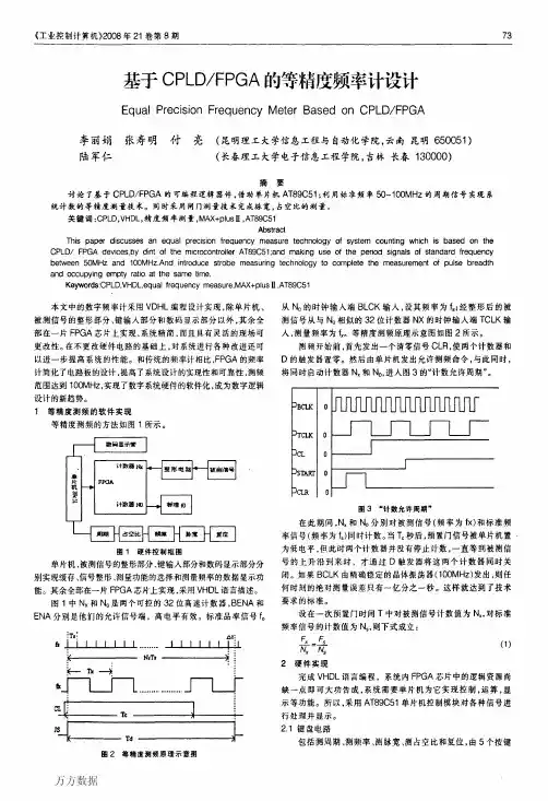
《工业控制计算机}2008年21卷第8期73基于CPLD/FPGA的等精度频率计设计EqualPrecisionFrequencyMeterBasedonCPLD/FPGA李丽娟张寿明付亮(昆明理工大学信息工程与自动化学院,云南昆明650051)陆军仁(长春理工大学电子信息工程学院,吉林长春130000)摘要讨论了基于CPLD/FPGA的可编程逻辑器件,借助单片机AT89C51;利用标准频率50~100MHz的周期信号实现系统计数的等精度测量技术。
同时采用闸门测量技术完成脉宽。
占空比的测量。
关键词:CPLD,VHDL,精度频率测量,MAX+plus11,AT89C51AbstractThispaperdiscussesanequalprecisionfrequencymeasuretechnologyofsystemcountingwhichisbasedontheCPLD/FPGAdevices,bydintofthemicrocontrollerAT89C51;andmakinguseoftheperiodsignalsofstandardfrequencybetween50MHzand100MHz.Andintroducestrobemeasuringtechnologytocompletethemeasurementofpulsebreadthandoccupyingemptyratioatthesametime.Keywords:CPLD.VHDL,equalfrequencymeasure.MAX+plusⅡ.AT89C51本文中的数字频率计采用VDHL编程设计实现,除单片机、被测信号的整形部分、键输入部分和数码显示部分以外,其余全部在一片FPGA芯片上实现,系统精简,而且具有灵活的现场可更改性。
在不更改硬件电路的基础上,对系统进行各种改进还可以进一步提高系统的性能。
和传统的频率计相比,FPGA的频率计简化了电路板的设计,提高了系统设计的实现性和可靠性,测频范围达到100MHz,实现了数字系统硬件的软件化,成为数字逻辑设计的新趋势。
基于FPGA 与DSP 的等精度数字频率计设计(湖南铁道职业技术学院)唐亚平摘要:本设计根据等精度的多周期同步测频原理,采用Altera 公司的FLEX10K10系列FPGA 和TI 的TMS320VC5402进行硬件电路的设计。
各项实测表明,多周期同步测频法是正确、合理和可靠的。
关键词:多周期同步测频法;FPGA ;数字信号处理器中图分类号: TN713 文件标识码: BThe Design of Equal Precision Digital Cymometer based on FPGA and DSP(Hunan Railway Professional Technology Collage)TANG Ya-pingAbstract: This paper introduces a method of measuring frequency by multi-period synchronous theory. And based on it , the FPGA and Digital Signal Processor implement the cymomenter . All the test proved that the multi-period synchronous measuring method is correct and stable.Keywords: multi-period synchronous measuring method;FPGA ;DSP频率检测是电子测量领域的最基本也是最重要的测量之一,频率信号抗干扰强,易于传输,可以获得较高的测量精度, 所以测频率方法的研究越来越受到重视。
本设计是以FPGA 为核心的等精度率数字频率计,采用TI 公司的TMS320VC5402 DSP 芯片和Altera 公司的FLEX10K10系列FPGA,采用多周期同步测频原理,实现了高精度的恒误差频率测量,在使用过程中无需量程切换。
科技广场2009.50引言常用的测频方法主要有测频法和测周期法两种。
测频法就是在确定的闸门时间T W 内,记录被测信号的变化周期数(或脉冲个数)N X ,则被测信号的频率f x =N X /T W 。
测周期法需要有标准频率信号f s ,在待测信号的一个周期内,记录标准频率的周期数N s ,则被测信号的频率为f x =f s /N s 。
这两种方法的计数值会产生个字误差,并且测量精度与计数器中记录的数值有关。
为了保证测量精度,一般对低频信号采用测周期法,对于高频信号采用测频法,因此测试时很不方便。
针对以上问题,本文提了一种基于等精度测频原理的频率计,给出了一种基于FPGA 的设计方案。
1等精度测量方法等精度测量方法是在直接测频方法的基础上发展起来的。
它的闸门时间不是固定的值,而是被测信号的整数倍,即与被测信号同步。
因些,排除了对被测信号计数所产生的个字误差,并且达到了在整个测量频段的等精度测量,其测频原理如图一所示。
在测量过程中,有两个计数器分别对标准和被测信号同时计数。
首先给出闸门开启信号(预置闸门上升沿),此时计数器并不开始计数,而是等到被测信号的上升沿到来时,计数器才真正开始计数。
然后预置闸门关闭信号(下降沿)到时,计数器并不立即停止计数,而是等到被测信号的上升沿到来时才结束计数,完成一次测量过程。
可以看出,实际闸门时间t 与预置闸门时间t 1并不严格相等,但差值不会超过被测信号的一个周期。
设在一次实际闸门时间t 中计数器对被测信号的计数值为N X ,对标准信号的计数值为N S ,标准信基于FPGA的等精度数字频率计的研究与实现Design and Realization of Equal-precisions Digital Frequency Meter Based on FPGA曾任贤Zeng Renxian(南昌工程学院电气与电子工程系,江西南昌330099)(Department of Electrical and Electronics Engineering ,Nanchang Institute of Technology,Jiangxi Nanchang 330099)摘要:本文提出了一种基于等精度测频原理的频率计,给出了一种基于FPGA 的设计方案。
设计研发2020.07基于FPGA数字等精度频率计的设计张洋(重庆幼儿师范高等专科学校,重庆,404047)摘要:等精度频率计是在数字逻辑电路中的典型应用,它也是现代微电子领域中不可缺少的测量仪器。
本设计就是根据等精度的测频基本原理,提出的整体设计方案。
以FPGA芯片为核心电路,釆用VHDL语言编写子电路程序组建出顶层原理图,通过运用Quartus II软件,进行编译仿真,最后下载到实验电路板。
依照实际中频率计的使用情况,设计了八位数码管显示的等精度频率计,能够提高频率测量的精准度,减少测量误差。
关键词:等精度;现场可编程门系列(FPGA);VHDL编程;频率计Design of digital equal precision frequency meter based on FPGAZhang Yang(Chongqing Preschool education College,Chongqing,404047)Abstract:Equal-precision frequency meter is a typical application in digital logic circuit,it is also an indispensable measuring instniment in modern microelectronics field.This design is basedon the basic principle of frequency measurement of equal precision,the overall design ing FPGA chip as the core circuit using nguage program set up a top-level sub-circuit schematics, through the use of Quartus II software,compiled Simulation,and finally downloaded to the breadboard.In accordance with the actual use of the frequency meter designed eight digital display precision frequency meter.Frequency measurement accuracy can be improved,to reduce measuremerrt errors. Keywords:precision;Field Programmable Gate series(FPGA);VHDL programming;frequency meter1概述数字等精度频率计是现代微电子领域中必不可少的测量仪器。
摘要摘要:根据等精度测量的原则,提出了一种基于FPGA的等进度数字频率计设计方案。
介绍了等精度的多周期同步测频原理,并对其测量精度和特点同传统测量方法进行了对比分析,证明了多周期同步测频方法的优势。
基于周立功公司生产的EasyFPGA030开发板,在Libero8.5集成开发软件环境下,采用硬件编程语言VerilogHDL编写计数器模块,除法器模块,并且用Synplify进行综合,ModelSim进行仿真并且给出它们的仿真结果,Designer进行布局布线,利用FlashPro和并口线下载到开发板上。
利用AT89C51单片机与共阳极LED数码管对测量结果进行动态显示。
利用74LS244三态缓冲器和三极管对电流进行放大,使得LED数码管更亮。
利用74LS14集成施密特触发器的反相器进行信号的整形。
经过仿真下载验证,能够实现等精度测频功能,频率测量范围1Hz~1MHz,证明该设计方案切实可。
关键词:等精度;频率测量;FPGA;VerilogHDL;Libero。
AbstractAbstract: According to the principle of measurement etc precision, proposed based on FPGA digital frequency of design project progress. Introduces the principle of frequency measurement with etc precision and synchronous, and comparative analysis the measurement precision and features with the traditional measuring method. With more than proved step frequency method with etc precision and synchronous has periodic advantage.Based on the ZhouLiGong company production EasyFPGA030 development board, in Libero8.5 integrated software development environment, using hardware VerilogHDL programming language to write counter module, divide module. With Synplify synthetically, with ModelSim simulation giving simulation results, Designer layout wiring. Using FlashPro download the design to development board.Use MUC and LED digital tube to show the measurement results. Use74LS244 tristate buffers and transistor to amplify current that LED digital tube brighter. Use 74LS14 Schmitt toggle integration to plastic signal.Through simulation and download to the development board, can achieve the function of frequency measurement etc precision, Frequency measurement range from 1Hz to 1MHz. Proof of this scheme is feasible,Keywords: equal precision, frequency measurement, FPGA, Libero, HDL 毕业设计(论文)原创性声明和使用授权说明原创性声明本人郑重承诺:所呈交的毕业设计(论文),是我个人在指导教师的指导下进行的研究工作及取得的成果。
武汉轻工大学毕业设计外文参考文献译文本2013届原文出处:from Vin Skahill.VHDL for Programmable Logic page 76-88毕业设计题目:基于FPGA的数字频率计设计院(系):电气与电子工程学院专业名称:电子信息科学与技术学生姓名:学生学号:指导教师:Introduction of digital frequency meterDigital Frequency is an indispensable instrument of communications equipment, audio and video, and other areas of scientific research and production . In addition to the plastic part of the measured signal, and digital key for a part of the show, all the digital frequency using Verilog HDL designed and implemented achieve in an FPGA chip. The entire system is very lean, flexible and have a modification of the scene.1 、And other precision measuring frequency PrincipleFrequency measurement methods can be divided into two kinds:(1) direct measurement method, that is, at a certain time measurement gate measured pulse signal number.(2) indirect measurements, such as the cycle frequency measurement, VF conversion law. Frequency Measurement indirect measurement method applies only to low-frequency signals.Based on the principles of traditional frequency measurement of the frequency of measurement accuracy will be measured with the decline in signal frequency decreases in the more practical limitations, such as the accuracy and frequency of measurement not only has high accuracy, but also in the whole frequency region to maintain constant test accuracy. The main method of measurement frequency measurement Preferences gated signal GATE issued by the MCU, GATE time width on the frequency measurement accuracy of less impact, in the larger context of choice, as long as the FPGA in 32 of 100 in the counter b M Signals are not overflow line, in accordance with the theoretical calculation GATE time can be greater than the width Tc 42.94 s, but due to the single-chip microcomputer data processing capacity constraints, the actual width of less time, generally in the range of between 0.1 s choice, that is, high-frequency, shorter gate;, low gate longer. This time gate width Tc based on the size of the measured frequency automatically adjust frequency measurement in order to achieve the automatic conversion range, and expanded the range of frequency measurement; realization of the entire scope of measurement accuracy, reduce the low-frequency measurement error.The design of the main methods of measuring the frequency measurement and control block diagram as shown in Figure 1. Figure 1 Preferences gated signal GA TE issued by the MCU, GA TE time width of less frequency measurement accuracy, in the larger context of choice, as long as the FPGA in 32 of 100 in the counter b Msignal Overflow will do, according to theoretical calculations GA TE time width T c can be greater than 42194 s, but due to the single-chip microcomputer data processing capacity constraints, the actual width of less time, generally 10 to 011 s in the inter-choice, that is, high - band, the gate time shorter, low gate longer. This time gate width based on the measured T c automatically adjust the size of frequency measurement frequency range to achieve the automatic conversion, and expanded the range of frequency measurement; realization of the entire scope of measurement accuracy, reduce the low-frequency measurement error.2、Frequency of achievingFrequency Measurement accuracy of such method. Can be simplified as shown in the diagram. Map CNT1 and CNT2 two controllable counter, standard frequency (f) signal from the CN F1 clock input cI K input, the signal measured after the plastic (f) CNT2 clock input cI K input. Each counter in the CEN input as enable end, used to control the counter count. When the gate signal is HIGH Preferences (Preferences start time). Signal measured by the rising edge of the D flip-flop input, launched at the same time with two counts of juice; Similarly, when preferences for low gate signal (the end of Preferences time), the rising edge of the measured signals through D Trigger output end of the counter to stop counting.3、And the median frequency of relevant indicatorsMedian: At the same time the figures show that up to the median. The usual eight-count frequency of only several hundred yuan can buy. For high precision measurements, nine just beginning, the middle is 11, 13 can be relatively high.Overflow of:-the ability to promote itself to overflow the equivalent of the total. Some of the frequency with overflow function, which is the highest overflow does not display only shows that the bit behind, in order to achieve the purpose of the median. Here is the estimated value of individual indicators.Speed: namely, the number of per second. With the high number of measurement particularly slow but also lose its significance. Counting of the usual eight frequency measurement 10 MHz signals, one second gate will be 10000000 Hz, which is actually seven (equivalent to the median number of common admission after the value), to obtain eight needed 10 seconds gate ; to obtain nine needed 100 seconds gate, followed by analogy, shows that even the permission of 11 need 10,000 second measurement time. But in any case, or seven per second. Therefore, to fast must be a few high speed.Distinction: it is like a minimum voltage meter can tell how much voltage indicators are similar, the smaller the better, unit ps (picoseconds). 1000ps = 1ns. Suppose you use the frequency of 1 ns to differentiate between an e-12 error, we need a ns/1e-12 = 1000 seconds. Also assume that you have a frequency resolution of 100 ps, the measurement time can be shortened by 10 times for 100 seconds, or can be in the same 1000 second measured under an e-14 Error.4、Time and Frequency MeasurementCompared to traditional methods of circuit design, EDA technology uses VHDL language to describe circuit system, including circuit structure, behavior, function and interface logic. Verilog HDL description of a multi-level system hardware functions, and support top-down design features. Designers can not understand the hardware structure. Start from the system design, on the top floor of a system block diagram of the structure and design, in a diagram with Ver-ilog HDL acts on the circuit description and simulation and error correction, and then the system level verification, and finally use logic synthesis optimization tool to create specific gate-level logic circuit netlist, download to the specific FPGA device to in order to achieve FPGA design.Time and frequency measurement is an important area of electronic measurement. Frequency and time measurement has been receiving increasing attention, length, voltage, and other parameters can be transformed into a frequency measurement and related technologies to determine. Based on the more traditional method of synchronization cycle, and has proposed a multi-cycle synchronization and quantitative method of measuring delay frequency method.The most simple method of measuring the frequency of direct frequency measurement method. Direct Frequency Measurement is scheduled to enter the gate signal pulse, the adoption of the necessary counting circuit, the number of pulses are filled to calculate the frequency or analyte signal cycle. In the direct frequency measurement on the basis of the development of multi-cycle synchronous measurement method, in the current frequency monitoring system to be more widely used. Multi-cycle synchronization frequency measurement technology actual gate time is not fixed value, but the measured signals in the whole cycle times, and the measured signal synchronization, thereby removing the measured signal count on when the word ± 1 error, measurement accuracy greatly improved, and reached in the entire spectrum of measurement, such as precision measurement.In the time-frequency measurement method, the multi-cycle synchronization is a high precision, but still unresolved ± a word error, mainly because of the actual gate edge and standard frequency synchronization is not filling pulse edge Tx=N0T0-△t2+△t1, if accurately measured short interval Δ t1 and Δ t2, will be able to accurately measure time intervals Tx, eliminating ± a word counting error, so as to further enhance accuracy.To measure a short time interval Δ t1 and Δ t2, commonly used analog interpolation method with the cursor or more combined cycle synchronization, although accuracy is greatly improved, but eventually failed to resolve ± a word error this fundamental issue, but these methods equipment complex and not conducive to the promotion.To obtain high precision, fast response time, simple structure and the frequency and time measurement method is relatively difficult.Judging from the structure as simple as possible at the same time take into account the point of view of accuracy, multi-cycle synchronization and delay based on the quantitative methods in a short period of time interval measurement, achieved within the scope of broadband, such as high-resolution measurement accuracy.Quantified by measuring short time intervals DelayPhotoelectric signal can be in a certain stability in the medium of rapid spread, and in different media have different delay. By signals generated by the delay to quantify, and gave a short period of time interval measurement.The basic principle is that "delay serial, parallel count", and different from the traditional counter serial number, that is, to signal through a series of delay unit, the delay unit on the delay stability, under the control of the computer Delay on the state of high-speed acquisition and data processing, for a short period of time to achieve accurate measurement interval.Delay quantitative thinking depend on the realization of the delay stability delay unit, the unit depends on the resolution of the delay time delay element.Delay device as a unit can be passive conduit, or other active devices gate circuit. Among them, Traverse shorter delay time (nearly the speed of light transmission delay), the gate delay time longer. Taking into account delays can be predictive ability final choice of the CPLD devices, the realization of the short time interval measurement.Will be the beginning of a short time interval signal sent delay in thetransmission chain, when the advent of the end of signal, this signal delay in the delay in the chain latch state, read through the CPU, the judge signal a delay unit on the few short-term time interval can be the size of the unit decided to delay resolution of the unit delay time.Generally speaking, in order to measure both short interval, the use of two modules delay and latches, but in reality, given the time software gate large enough to allow completion from the number of CPU operation, which can be measured in the time int erval taken before the end of a short period of time at Δ t1 corresponding delay the number of units through the control signals must be used only a delay and latches units, it saves CPLD internal resources. Synchronization and multi-cycle latency to quantify the method of combining The formula is:T=n0t0+n1t1-n2t1On, n0 for the filling pulse of value; t0 for filling pulse cycle, that is 100 ns; n1 for a short period of time at Δ t1 corresponding delay the number of modules; n2 for a short period of time at Δ t2 corresponding delay unit Number; t1 quantify delay devices for the delay delay unit volume (4.3 ns). In this way, using multi-cycle synchronization and realized the gate and measured signal synchronization; Delay of using quantitative measurement of the original measured not by the two short intervals, to accurately measure the size of the actual gate, it raised frequency measurement accuracy.The frequency synthesizer output frequency signal can only be transferred to the minimum 10 Hz, XDU-17 as a standard of measurement can be calculated prototype frequency measurement accuracy.For example, the measured signal is measured at 15.000010 MHz MHz signal to 5.00001002, from the calculation can be seen above, the resolution of the prototype has reached ns order of magnitude below from the perspective of theoretical analysis to illustrate this point.It has been anal yzed,multi-cycle synchronization frequency measurement, the measurement uncertainty:When the input f0 10 MHz, 1 s gate time, the uncertainty of measurement of ±1×10⁻⁷/s. When the measurement and quantification of delay circuit with short intervals combined, the uncertainty of measurement can be derived from the following.In the use of cycle synchronization, multi-analyte Tx for the cycle value of T0time base for the introduction of the cycle.Tx= NT0+△t1-△t2Delay circuit and quantitative combined:Tx= NT0+(N1-N2)td±δTxHere, δTx not for the accuracy of the measurement.On the decline of the share: δTx≤±2tdFrom the details of the measuring accuracy of this method depends on the td, and its direct impact on the stability and size of the uncertainty of measurement. Therefore, the application of methods, counters can be achieved within the entire frequency range, such as the accuracy of measurement, and measurement accuracy is significantly improved, measuring improvement in resolution to 4.3 ns, and the elimination of the word ± a theoretical error, the accuracy is increased by 20 times.CONCLUSION This paper presents a new method of measuring frequency. Based on the frequency of this method of digital integrated circuit in a CPLD, greatly reduced the volume of the entire apparatus, improved reliability, and a high-resolution measurements.5 、Frequency of VHDL DesignALTERA use of the FPGA chip EPF10K10 companies, the use of VHDL programming language design accuracy of frequency, given the core course. ISPEXPER simulation, design verification is successful, to achieve the desired results. Compared to the traditional frequency of FPGA simplify the circuit board design. Increased system design and the realization of reliability, frequency measurement range of up to 100 MHz and achieve a digital system hardware and software, which is digital logic design the new trend.The design uses the AL TERA EPF10K FPGA chip, the chip pin the delay of 5 ns, frequency of 200 MHz,the standardization of application VHDL hardware description language has a very rich data types, the structure of the model of a complex digital system logic design and computer simulation, and gradually improve after the automatic generation integrated to meet the requirements of the circuit structure of the digital logic can be realized, then can be downloaded to programmable logic devices, to complete design tasks.数字频率计的介绍数字频率计是通信设备、音、视频等科研生产领域不可缺少的测量仪器。
FPGA简易数字频率计课程设计报告The Design Of Simple Digital Frequency Meter Base On FPGAABSTRACTThe design is based on FPGA digital frequency of a simple plan, use Verilog hardware design realized the frequency of internal function module, the accuracy of the measurement method, etc NIOS and FPGA, soft nuclear CPU embedded systems, using the SOPC constitute NIOS soft check data management man-machine floating point calculations, exchange, with real-time display interface chip traditional FPGA + MCU solutions, system is much more flexible than small volume and low consumption, have advantages of hardware and software systems in programmable functions.This design method of measuring frequency by measuring method is compared with direct frequency measurement method, and the measuring accuracy of ZhouFaYou characteristics. Front-end signal input by AD811 amplifier to recuperate broadband amplification, weak s ignal by comparator plastic, after using measurements on FPGA, system of good real-time, high precision.Key words:Equal precision Frequency counter FPGA NIOS Verilog摘要:本设计是基于FPGA的一个简易数字频率计,利用Verilog 硬件描述语言设计实现了频率计内部功能模块,采用了等精度测量的方法,并结合NIOS软核CPU嵌入FPGA,构成SOPC系统,利用NIOS软核对数据浮点运算处理,管理人机交换界面实时显示,跟传统FPGA+单片机的多芯片系统方案相比更加灵活,系统体积小和功耗小等优势,具备软硬件在系统可编程的功能。
摘要在电子技术中,频率是最基本的参数之一,并且与许多电参量的测量方案、测量结果都有十分密切的关系,因此频率的测量就显得十分重要。
数字频率计是数字电路中的典型应用,是电子测量与仪表技术最基础的电子仪器之一,是计算机、通讯设备、音频视频等科研生产领域不可缺少的测量仪器。
与传统的频率计相比,数字频率计具有精度高、测量范围大、可靠性好等优点。
是频率测量的重要手段之一。
该论文研究基于FPGA的数字频率计的设计,在QuartusII环境中,运用VHDL语言完成数字频率计的设计,并对设计进行综合、编译、仿真。
通过仿真分析,证明该频率计测量结果的正确性。
本文的主要介绍了数字频率计的基本内容和重要性,并对数字频率计的国内外研究现状进行了总结;数字频率计设计开发环境,并对FPGA、QuartusII、VHDL进行了详细介绍对开发流程详细说明;根据实际需要对数字频率计设计方法、方案进行了可行性比较,并对其实现的功能进行了具体要求,对设计模块进行了划分,并定义了每个模块所实现的功能;用VHDL语言编程,具体实现频率计各个模块的功能, 对数字频率计仿真并验证其功能。
关键词: FPGA;QuartusII;VHDL;频率计AbstractIn electronics,frequency is one of the most basic parameters.And it have a close relationship with many measurement program of electrical parameters and measurement results, so the measurement of frequency is very important.Digital frequency meter is a typical applications in digital circuit,and one of the most basic electronic devices in electronic measurement and instrumentation technology.Digital frequency meter is an indispensable measuring instruments for scientific research and production as computers, communications equipment, audio, video. Compared with the conventional frequency counter,digital frequency meter have a high accuracy, measurement range and a good reliability. It is one of important measure for frequency measurement:The thesis research in design of digital frequency meter,FPGA-based. VHDL language is used to complete the design of digital frequency meter in QuartusII,and completed thesis with composited, compiled, simulated. Through simulation and analysis, The results show that the accuracy of measure for the frequency. This article mainly introduces the importance and basic content of digital frequency meter, and current research is summarized .the main tasks and content of this design are summarized.Design and development environment of digital frequency meter are introduced.FPGA, QuartusII and VHDL are described in detail.According to the actual needs of the digital frequency meter, design method and design program are compared to achieve the functions of their specific requirements, and defines the functions of each module to achieve the function.Keywords : FPGA,QuartusII ,VHDL,digital frequency met目录摘要 (I)Abstract (II)第1章绪论 (1)1.1 课题背景与意义 (1)1.2 课题目的 (1)1.3 技术指标 (1)第2章FPGA开发相关知识简介 (3)2.1 FPGA的介绍 (3)2.2 FPGA开发环境 (4)软件开发环境——Quartus II的介绍 (4)软件仿真环境——Modelsim的介绍 (5)2.3 硬件描述语言——Verilog HDL (6)2.4 FPGA开发流程 (8)本章小结 (11)第3章频率计的设计方案 (12)3.1 系统的总体设计 (12)3.1.1 设计思路 (12)频率计的基本原理 (12)3.2 数字频率计原理方框图 (13)本章小结 (13)第4章频率计的实现 (14)4.1 时钟信号分频模块的设计 (14)4.2 测频控制信号发生模块的设计 (15)4.3 十进制计数模块的设计 (16)4.4 八位十进制计数模块的设计 (18)4.5 三十二位锁存器模块的设计 (20)4.6 顶层模块的设计 (20)本章小结 (23)结论 (24)致谢 (25)参考文献 (26)附录1 译文 (27)附录2 英文参考资料 (30)第1章绪论1.1 课题背景与意义在电子技术中,频率是最基本的参数之一,并且与许多电参量的测量方案、测量结果都有十分密切的关系,频率的测量就显得尤为重要,而频率计的研究工作更具有重大的科研意义。
封面作者:Pan Hongliang仅供个人学习20世纪末,数字电子技术得到了飞速发展,有力地推动和促进了社会生产力的发展和社会信息化的提高,数字电子技术的应用已经渗透到人类生活的各个方面。
从计算机到手机,从数字电话到数字电视,从家用电器到军用设备,从工业自动化到航天技术,都尽可能采用了数字电子技术。
现代电子设计技术的核心是EDA技术。
EDA技术就是以计算机为工具,在EDA软件平台上,对硬件语言HDL为系统逻辑描述手段完成的设计文件,自动的完成逻辑编译、逻辑化简、逻辑综合及优化、逻辑仿真,直至对特定目标芯片的适配编译、逻辑映射和编程下载等工作(文本选用的开发工具为Altera公司的MAX+PLUSII)。
EDA的仿真测试技术只需要通过计算机就能对所设计的电子系统从各种不同层次的系统性能特点完成一系列准确的测试与仿真操作,大大提高了大规模系统电子设计的自动化程度。
设计者的工作仅限于利用软件方式,即利用硬件描述语言(如VHDL)来完成对系统硬件功能的描述。
EDA技术使实现,极大地提高了设计效率,缩短了设计周期,节省了设计成本。
今天EDA技术已经成为电子设计的重要工具,无论是设计芯片还是设计系统,如果没有EDA工具的支持,都将是难以完成的。
EDA工具已经成为现代电路设计工程师的重要武器,正在发挥越来越重要的作用。
为了提高自身的实践能力与专业知识应用能力,为了更快地与社会实际和社会需要接轨,这次毕业设计我选择了以EDA技术为方向,设计数字频率计,在所参考的文献中,都包含了这一技术。
相信通过此次毕业设计将为我更全面更系统更深入地掌握EDA技术打下良好的基础。
EDA发展历程EDA技术伴随着计算机、集成电路、电子系统设计的发展,经历了三个发展阶段,即:20世纪70年代发展起来的CAD技术;0世纪80年代开始应用的CAE技术;20世纪90年代后期,出现的以硬件描述语言、系统级仿真和综合技术为特征的EDA技术,这时的EDA工具不仅具有电子系统设计的能力,而且能提供独立于工艺和厂家的系统级设计能力,具有高级抽象的设计构思手段。
基于FPGA的等精度数字频率计的设计中英文翻译中文译文:数字频率计的介绍数字频率计是通信设备、音、视频等科研生产领域不可缺少的测量仪器。
采用Verilog HDL编程设计实现的数字频率计,除被测信号的整形部分、键输入部分和数码显示部分外,其余全部在一片FPGA芯片上实现。
整个系统非常精简,且具有灵活的现场可更改性。
1 等精度测频原理频率的测量方法主要分为2 种方法:(1) 直接测量法, 即在一定的闸门时间内测量被测信号的脉冲个数。
(2) 间接测量法, 例如周期测频法、V F 转换法等。
间接测频法仅适用测量低频信号。
基于传统测频原理的频率计的测量精度将随被测信号频率的下降而降低, 在实用中有较大的局限性, 而等精度频率计不但具有较高的测量精度, 而且在整个频率区域能保持恒定的测试精度。
频率测量方法的主要测量预置门控信号GATE是由单片机发出,GATE的时间宽度对测频精度影响较少,可以在较大的范围内选择,只要FPGA中32 b计数器在计100 M信号不溢出都行,根据理论计算GATE的时间宽度Tc可以大于42.94 s,但是由于单片机的数据处理能力限制,实际的时间宽度较少,一般可在10~0.1 s间选择,即在高频段时,闸门时间较短;低频时闸门时间较长。
这样闸门时间宽度Tc依据被测频率的大小自动调整测频,从而实现量程的自动转换,扩大了测频的量程范围;实现了全范围等精度测量,减少了低频测量的误差。
本设计频率测量方法的主要测量控制框图如图1 所示。
图1 中预置门控信号GA TE 是由单片机发出, GA TE的时间宽度对测频精度影响较少, 可以在较大的范围内选择, 只要FPGA 中32 b 计数器在计100M 信号不溢出都行, 根据理论计算GA TE 的时间宽度T c 可以大于42194s, 但是由于单片机的数据处理能力限制, 实际的时间宽度较少, 一般可在10~011 s 间选择, 即在高频段时,闸门时间较短; 低频时闸门时间较长。
这样闸门时间宽度T c 依据被测频率的大小自动调整测频, 从而实现量程的自动转换, 扩大了测频的量程范围; 实现了全范围等精度测量, 减少了低频测量的误差。
2 频率计的实现等精度测频的实现方法。
可简化为CNT1和CNT2是两个可控计数器,标准频率(f )信号从CN F1的时钟输入端cI K输入,经整形后的被测信号(f )从CNT2的时钟输入端cI K输入。
每个计数器中的CEN输入端为使能端,用来控制计数器计数。
当预置闸门信号为高电平(预置时间开始)时。
被测信号的上升沿通过D 触发器的输入端,同时启动两个汁数器计数;同样,当预置闸门信号为低电平(预置时间结束)时,被测信号的上升沿通过D触发器的输出端,使计数器停止计数。
3 频率计的位数及相关指标位数:同时最多能显示的数字位数。
平常计数式的8位频率计只有几百元就可买到。
对于高精度的测量,9位刚刚开始,11位算中等,13位才能算比较高级。
溢出位:把溢出位算进去的总等效位。
有些频率计带有溢出功能,即把最高位溢出不显示而只显示后面的位,以便达到提高位数的目的。
这里个别指标是估计值。
速度:即每秒能出多少位。
有了高位数的但测量特别慢也失去了意义。
平常计数式的8位频率计,测量10MHz信号、1秒闸门能得到10,000,000Hz,这实际上才是7位(位数等于取常用对数后的值),要想得到8位,需要10秒闸门;要想得到9位,需要100秒闸门,依次类推,即便显示允许,11位需要10000秒的测量时间了。
但无论如何,还是每秒7位。
因此,要想快速得到高位数则必须高速度。
分辨:这就像一个电压表最小可以分辨出多大的电压的指标是类似的,越小越好,单位ps(皮秒)。
1000ps=1ns。
假设你用1ns的频率计要分辨出1e-12的误差,就需要1ns/1e-12=1000秒的时间。
而假设你有另外一个频率计的分辨是100ps,那么测量时间就可以缩短10倍为100秒,或者可以在相同的1000秒下测量出1e-14的误差。
4 时间频率测量相比传统的电路系统设计方法,EDA技术采用VHDL语言描述电路系统,包括电路的结构、行为方式、逻辑功能及接口。
Verilog HDL具有多层次描述系统硬件功能的能力,支持自顶向下的设计特点。
设计者可不必了解硬件结构。
从系统设计入手,在顶层进行系统方框图的划分和结构设计,在方框图一级用Ver-ilog HDL对电路的行为进行描述,并进行仿真和纠错,然后在系统一级进行验证,最后再用逻辑综合优化工具生成具体的门级逻辑电路的网表,下载到具体的FPGA器件中去,从而实现FPGA的设计。
时间频率测量是电子测量的重要领域。
频率和时间的测量已越来越受到重视,长度、电压等参数也可以转化为与频率测量有关的技术来确定。
本文通过对传统的多周期同步法进行探讨,提出了多周期同步法与量化时延法相结合的测频方法。
最简单的测量频率的方法是直接测频法。
直接测频法就是在给定的闸门信号中填入脉冲,通过必要的计数电路,得到填充脉冲的个数,从而算出待测信号的频率或周期。
在直接测频的基础上发展的多周期同步测量方法,在目前的测频系统中得到越来越广泛的应用。
多周期同步法测频技术的实际闸门时间不是固定的值,而是被测信号的整周期倍,即与被测信号同步,因此消除了对被测信号计数时产生的±1个字误差,测量精度大大提高,而且达到了在整个测量频段的等精度测量,在时频测量方法中,多周期同步法是精度较高的一种,但仍然未解决±1个字的误差,主要是因为实际闸门边沿与标频填充脉冲边沿并不同步Tx=N0T0-△t2+△t1,如果能准确测量出短时间间隔Δt1和Δt2,也就能够准确测量出时间间隔Tx,消除±1个字的计数误差,从而进一步提高精度。
为了测量短时间间隔Δt1和Δt2,通常使用模拟内插法或游标法与多周期同步法结合使用,虽然精度有很大提高,但终未能解决±1个字的误差这个根本问题,而且这些方法设备复杂,不利于推广。
要得到精度高,时间响应快,结构简单的频率和时间测量方法是比较困难的。
从结构尽量简单同时兼顾精度的角度出发,将多周期同步法与基于量化时延的短时间间隔测量方法结合,实现了宽频范围内的等精度高分辨率测量。
量化时延法测短时间间隔光电信号可以在一定的介质中快速稳定的传播,且在不同的介质中有不同的延时。
通过将信号所产生的延时进行量化,实现了对短时间间隔的测量。
其基本原理是“串行延迟,并行计数”,而不同于传统计数器的串行计数方法,即让信号通过一系列的延时单元,依靠延时单元的延时稳定性,在计算机的控制下对延时状态进行高速采集与数据处理,从而实现了对短时间间隔的精确测量。
量化时延思想的实现依赖于延时单元的延时稳定性,其分辨率取决于单位延时单元的延迟时间。
作为延时单元的器件可以是无源导线,有源门器件或其他电路。
其中,导线的延迟时间较短(接近光速传播的延迟),门电路的延迟时间相对较长。
考虑到延迟可预测能力,最终选择了CPLD器件,实现对短时间间隔的测量。
将短时间间隔的开始信号送入延时链中传播,当结束信号到来时,将此信号在延时链中的延时状态进行锁存,通过CPU读取,判断信号经过的延时单元个数就可以得到短时时间间隔的大小,分辨率决定于单位延时单元的延时时间。
一般来讲,为了测量两个短时间间隔,使用两组延时和锁存模块,但实际上,给定的软件闸门时间足够大,允许CPU完成取数的操作,即能够在待测时间间隔结束之前取走短时间隔Δt1对应的延时单元的个数,通过一定的控制信号,可以只用一组延时和锁存单元,这样可以节省CPLD内部的资源。
利用多周期同步与量化时延相结合的方法,计算公式为:T=n0t0+n1t1-n2t1上式中,n0为对填充脉冲的计数值;t0为填充脉冲的周期,即100ns;n1为短时间隔Δt1对应的延时单元的个数;n2为短时间隔Δt2对应的延时单元的个数;t1为量化延迟器件延时单元的延迟量(4.3ns)。
这样,利用多周期同步法,实现了闸门和被测信号同步;利用量化时延法,测量了原来测不出来的两个短时间间隔,从而准确地测量了实际闸门的大小,也就提高了测频的精度。
由于频率合成器输出的频率信号最小只能调到10Hz,把XDU-17的测量值作为标准,可以计算出样机测频的精度。
例如,被测信号为15.000010MHz时被测信号为5.00001002MHz时,从上面的计算可以看出,样机的分辨率已达ns量级,下面从理论分析的角度来说明这一点。
前面已经分析过,多周期同步法测频时,它的测量不确定度为:当输入f0为10MHz,闸门时间为1s时,测量的不确定度为±1×10⁻⁷/s。
当与量化延时测量与短时间间隔电路相结合时,测量的不确定度可以从下述推导出来。
在采用多周期同步法时,Tx为待测的多周期值,T0为采用的时基周期。
Tx= NT0+△t1-△t2与量化延时电路相结合后有:Tx= NT0+(N1-N2)td±δTx这里,δTx为测量的不准确度。
对上式微分得:\δTx≤±2td由上式可知,此方法的测量精度取决于td,它的稳定性与大小直接影响测量值的不确定度。
所以采用各种方法,计数器可在整个频率量程内实现等精度的测量,而且测量精度有显著提高,测量分辨率提高到4.3ns,且消除了±1个字的理论误差,精度提高了20多倍。
结束语本文将给出了一种新的测频方法。
基于此方法的频率计的数字电路部分集成在一片CPLD中,大大减小了整个仪器的体积,提高了可靠性,且达到了很高的测量分辨率。
5 频率计的VHDL 设计利用ALTERA公司的FPGA芯片EPF10K10,使用VHDL编程语言设计等精度频率计,给出核心程序,经过ISPEXPER仿真后,验证设计是成功的,达到预期结果。
传统的频率计相比,FPGA的频率计简化了电路板的设计,提高了系统设计的实现性和可靠性,测频范围达到100 MHz,实现了数字系统硬件的软件化,这是数字逻辑设计的新趋势。
本设计采用AL TERA 公司的FPGA 芯片EPF10K10, 该芯片管脚间的延迟为5 ns, 即频率为200MHz, 应用标准化的硬件描述语言VHDL 有非常丰富的数据类型, 他的结构模型是层次化的, 利用这些丰富的数据类型和层次化的结构模型, 对复杂的数字系统进行逻辑设计并用计算机仿真, 逐步完善后进行自动综合生成符合要求的、在电路结构上可实现的数字逻辑, 再下载到可编程逻辑器件中, 即可完成设计任务。
--------------------译自文斯凯赫尔著的VHDL逻辑设计76-88页Introduction of digital frequency meter Digital Frequency of communications equipment, audio and video, and other areas of scientific research and production of an indispensable instrument. Programming using Verilog HDL Design and Implementation of the digital frequency, in addition to the plastic part of the measured signal, and digital key for a part of the show, all in an FPGA chip to achieve. The entire system is very lean, flexible and have a modification of the scene.1. And other precision measuring frequency PrincipleFrequency measurement methods can be divided into two kinds:(1) direct measurement method, that is, at a certain time measurement gate measured pulse signal number.(2) indirect measurements, such as the cycle frequency measurement, VF conversion law. Frequency Measurement indirect measurement method applies only to low-frequency signals.Based on the principles of traditional frequency measurement of the frequency of measurement accuracy will be measured with the decline in signal frequency decreases in the more practical limitations, such as the accuracy and frequency of measurement not only has high accuracy, but also in the whole frequency region to maintain constant test accuracy. The main method of measurement frequency measurement Preferences gated signal GATE issued by the MCU, GATE time width on the frequency measurement accuracy of less impact, in the larger context of choice, as long as the FPGA in 32 of 100 in the counter b M Signals are not overflow line, in accordance with the theoretical calculation GATE time can be greater than the width Tc 42.94 s, but due to the single-chip microcomputer data processing capacity constraints, the actual width of less time, generally in the range of between 0.1 s choice, that is, high-frequency, shorter gate;, low gate longer. This time gate width Tc based on the size of the measured frequency automatically adjust frequency measurement in order to achieve the automatic conversion range, and expanded therange of frequency measurement; realization of the entire scope of measurement accuracy, reduce the low-frequency measurement error.The design of the main methods of measuring the frequency measurement and control block diagram as shown in Figure 1. Figure 1 Preferences gated signal GA TE issued by the MCU, GA TE time width of less frequency measurement accuracy, in the larger context of choice, as long as the FPGA in 32 of 100 in the counter b M signal Overflow will do, according to theoretical calculations GA TE time width T c can be greater than 42194 s, but due to the single-chip microcomputer data processing capacity constraints, the actual width of less time, generally 10 to 011 s in the inter-choice, that is, high - band, the gate time shorter, low gate longer. This time gate width based on the measured T c automatically adjust the size of frequency measurement frequency range to achieve the automatic conversion, and expanded the range of frequency measurement; realization of the entire scope of measurement accuracy, reduce the low-frequency measurement error.2 .Frequency of achievingFrequency Measurement accuracy of such method. Can be simplified as shown in the diagram. Map CNT1 and CNT2 two controllable counter, standard frequency (f) signal from the CN F1 clock input cI K input, the signal measured after the plastic (f) CNT2 clock input cI K input. Each counter in the CEN input as enable end, used to control the counter count. When the gate signal is HIGH Preferences (Preferences start time). Signal measured by the rising edge of the D flip-flop input, launched at the same time with two counts of juice; Similarly, when preferences for low gate signal (the end of Preferences time), the rising edge of the measured signals through D Trigger output end of the counter to stop counting.3.And the median frequency of relevant indicatorsMedian: At the same time the figures show that up to the median. The usual eight-count frequency of only several hundred yuan can buy. For high precision measurements, nine just beginning, the middle is 11, 13 can be relatively high.Overflow of:-the ability to promote itself to overflow the equivalent of the total.Some of the frequency with overflow function, which is the highest overflow does not display only shows that the bit behind, in order to achieve the purpose of the median. Here is the estimated value of individual indicators.Speed: namely, the number of per second. With the high number of measurement particularly slow but also lose its significance. Counting of the usual eight frequency measurement 10 MHz signals, one second gate will be 10000000 Hz, which is actually seven (equivalent to the median number of common admission after the value), to obtain eight needed 10 seconds gate ; to obtain nine needed 100 seconds gate, followed by analogy, shows that even the permission of 11 need 10,000 second measurement time. But in any case, or seven per second. Therefore, to fast must be a few high speed.Distinction: it is like a minimum voltage meter can tell how much voltage indicators are similar, the smaller the better, unit ps (picoseconds). 1000ps = 1ns. Suppose you use the frequency of 1 ns to differentiate between an e-12 error, we need a ns/1e-12 = 1000 seconds. Also assume that you have a frequency resolution of 100 ps, the measurement time can be shortened by 10 times for 100 seconds, or can be in the same 1000 second measured under an e-14 Error.4. Time and Frequency MeasurementCompared to traditional methods of circuit design, EDA technology uses VHDL language to describe circuit system, including circuit structure, behavior, function and interface logic. Verilog HDL description of a multi-level system hardware functions, and support top-down design features. Designers can not understand the hardware structure. Start from the system design, on the top floor of a system block diagram of the structure and design, in a diagram with Ver-ilog HDL acts on the circuit description and simulation and error correction, and then the system level verification, and finally use logic synthesis optimization tool to create specific gate-level logic circuit netlist, download to the specific FPGA device to in order to achieve FPGA design.Time and frequency measurement is an important area of electronicmeasurement. Frequency and time measurement has been receiving increasing attention, length, voltage, and other parameters can be transformed into a frequency measurement and related technologies to determine. Based on the more traditional method of synchronization cycle, and has proposed a multi-cycle synchronization and quantitative method of measuring delay frequency method.The most simple method of measuring the frequency of direct frequency measurement method. Direct Frequency Measurement is scheduled to enter the gate signal pulse, the adoption of the necessary counting circuit, the number of pulses are filled to calculate the frequency or analyte signal cycle. In the direct frequency measurement on the basis of the development of multi-cycle synchronous measurement method, in the current frequency monitoring system to be more widely used. Multi-cycle synchronization frequency measurement technology actual gate time is not fixed value, but the measured signals in the whole cycle times, and the measured signal synchronization, thereby removing the measured signal count on when the word ± 1 error, measurement accuracy greatly improved, and reached in the entire spectrum of measurement, such as precision measurement.In the time-frequency measurement method, the multi-cycle synchronization is a high precision, but still unresolved ± a word error, mainly because of the actual gate edge and standard frequency synchronization is not filling pulse edge Tx=N0T0-△t2+△t1, if accurately measured short interval Δ t1 and Δ t2, will be able to accurately measure time intervals Tx, eliminating ± a word counting error, so as to further enhance accuracy.To measure a short time interval Δ t1 and Δ t2, commonly used analog interpolation method with the cursor or more combined cycle synchronization, although accuracy is greatly improved, but eventually failed to resolve ± a word error this fundamental issue, but these methods equipment complex and not conducive to the promotion.To obtain high precision, fast response time, simple structure and the frequency and time measurement method is relatively difficult.Judging from the structure as simple as possible at the same time take intoaccount the point of view of accuracy, multi-cycle synchronization and delay based on the quantitative methods in a short period of time interval measurement, achieved within the scope of broadband, such as high-resolution measurement accuracy. Quantified by measuring short time intervals DelayPhotoelectric signal can be in a certain stability in the medium of rapid spread, and in different media have different delay. By signals generated by the delay to quantify, and gave a short period of time interval measurement.The basic principle is that "delay serial, parallel count", and different from the traditional counter serial number, that is, to signal through a series of delay unit, the delay unit on the delay stability, under the control of the computer Delay on the state of high-speed acquisition and data processing, for a short period of time to achieve accurate measurement interval.Delay quantitative thinking depend on the realization of the delay stability delay unit, the unit depends on the resolution of the delay time delay element.Delay device as a unit can be passive conduit, or other active devices gate circuit. Among them, Traverse shorter delay time (nearly the speed of light transmission delay), the gate delay time longer. Taking into account delays can be predictive ability final choice of the CPLD devices, the realization of the short time interval measurement.Will be the beginning of a short time interval signal sent delay in the transmission chain, when the advent of the end of signal, this signal delay in the delay in the chain latch state, read through the CPU, the judge signal a delay unit on the few short-term time interval can be the size of the unit decided to delay resolution of the unit delay time.Generally speaking, in order to measure both short interval, the use of two modules delay and latches, but in reality, given the time software gate large enough to allow completion from the number of CPU operation, which can be measured in the time interval taken before the end of a short period of time at Δ t1 corresponding delay the number of units through the control signals must be used only a delay and latches units, it saves CPLD internal resources. Synchronization and multi-cyclelatency to quantify the method of combining The formula is:T=n0t0+n1t1-n2t1On, n0 for the filling pulse of value; t0 for filling pulse cycle, that is 100 ns; n1 for a short period of time at Δ t1 corresponding delay the number of modules; n2 for a short period of time at Δ t2 corresponding delay unit Number; t1 quantify delay devices for the delay delay unit volume (4.3 ns). In this way, using multi-cycle synchronization and realized the gate and measured signal synchronization; Delay of using quantitative measurement of the original measured not by the two short intervals, to accurately measure the size of the actual gate, it raised frequency measurement accuracy.The frequency synthesizer output frequency signal can only be transferred to the minimum 10 Hz, XDU-17 as a standard of measurement can be calculated prototype frequency measurement accuracy.For example, the measured signal is measured at 15.000010 MHz MHz signal to 5.00001002, from the calculation can be seen above, the resolution of the prototype has reached ns order of magnitude below from the perspective of theoretical analysis to illustrate this point.It has been anal yzed,multi-cycle synchronization frequency measurement, the measurement uncertainty:When the input f0 10 MHz, 1 s gate time, the uncertainty of measurement of ±1×10⁻⁷/s. When the measurement and quantification of delay circuit with short intervals combined, the uncertainty of measurement can be derived from the following.In the use of cycle synchronization, multi-analyte Tx for the cycle value of T0 time base for the introduction of the cycle.Tx= NT0+△t1-△t2Delay circuit and quantitative combined:Tx= NT0+(N1-N2)td±δTxHere, δ Tx not for the accuracy of the measurement.On the decline of the share: \δTx≤±2tdFrom the details of the measuring accuracy of this method depends on the td, and its direct impact on the stability and size of the uncertainty of measurement. Therefore, the application of methods, counters can be achieved within the entire frequency range, such as the accuracy of measurement, and measurement accuracy is significantly improved, measuring improvement in resolution to 4.3 ns, and the elimination of the word ± a theoretical error, the accuracy is increased by 20 times.CONCLUSION This paper presents a new method of measuring frequency. Based on the frequency of this method of digital integrated circuit in a CPLD, greatly reduced the volume of the entire apparatus, improved reliability, and a high-resolution measurements.5. Frequency of VHDL DesignALTERA use of the FPGA chip EPF10K10 companies, the use of VHDL programming language design accuracy of frequency, given the core course, ISPEXPER simulation, design verification is successful, to achieve the desired results. Compared to the traditional frequency, the frequency of FPGA simplify the circuit board design, increased system design and the realization of reliability, frequency measurement range of up to 100 MHz and achieve a digital system hardware and software, which is digital logic design the new trendThis design uses the AL TERA EPF10K10 FPGA chip, the chip pin the delay of 5 ns, frequency of 200 MHz, the standardization of application VHDL hardware description language has a very rich data types, the structure of the model is hierarchical, The use of these rich data types and levels of the structure model of a complex digital system logic design and computer simulation, and gradually improve after the automatic generation integrated to meet the requirements of the circuit structure of the digital logic can be realized, then can be downloaded to programmable logic devices, to complete design tasks.----------------------------------from Vin Skahill.VHDL forProgrammable Logic page76-88。