uBASIC用户指南中文版
- 格式:doc
- 大小:188.50 KB
- 文档页数:25
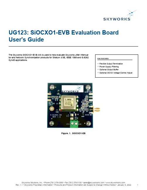
UG123: SiOCXO1-EVB Evaluation Board User's GuideThe Skyworks SiOCXO1-EVB (kit) is used to help evaluate Skyworks Jitter Attenua-tor and Network Synchronization products for Stratum 3/3E, IEEE 1588 and G.8262EVB FEATURES:SyncE applications.•Flexible Output Termination•Power Supply Filtering•Optional Output Buffer•Optional OCXO Voltage Control AdjustFigure .1. SiOCXO1-EBUG123: SiOCXO1-EVB Evaluation Board User's Guide • Quick Start1. Quick StartRefer to Figure 3.1 Functional Block Diagram on page 4, Figure 3.2 SiOCXO1-EB Shown Populated with an OCXO on page 4, and Figure 4.1 SiOCXO1-EB Configured with Si5348 EVB on page 6 to clarify the instructions below.1.Connect power to J1, and note that start-up current could be on the order of 1 amp. Check the manufacturers warm-up time.2.Connect SiOCXO1-EB output, J2, to the Si5348 REF clock input using the short SMA cable provided with the EVB kit.2. Top Layer View of BoardFigure 2.1. Top Layer View of BoardUG123: SiOCXO1-EVB Evaluation Board User's Guide • Top Layer View of Board3. Functional DescriptionThe SiOCXO1-EB is used in conjunction with Skyworks precision timing devices to facilitate characterization. The SiOCXO1-EB was designed to maximize output termination configurations as well as optional control voltage terminations. Resistors and capacitors are 0603, which makes it simple to remove and add various values. The SiOCXO1-EB bill of materials and PCB layouts are in Section 7. Bill of Materials and Section 6. Schematic. The block diagram for the board is provided below:Figure 3.1. Functional Block DiagramThe SiOCXO1-EB is intended to be a general use board for a 7-pin OCXO with 22x25 nominal package size, such as the Rakon P/N STP3158 12.8 MHz pictured below. See Section 6. Schematic for example measurements carried out using this OCXO.Figure 3.2. SiOCXO1-EB Shown Populated with an OCXO3.1 Power SupplyThe power supply voltage and current requirements are listed in the manufacturers data sheet. A 3.3 V ±5% supply is required. R6 may require modification if other voltages are used. Also, note the OCXO initial current can be on the order of 1A. Power supply filtering has been added to the evaluation board to minimize spurious response.3.2 Output Termination and Optional BufferIn most applications simple R C termination is used, as seen with R1 and C4 in Figure 6.1 SiOCXO1-EB Schematic on page 8. This is a resistor to optimize impedance matching and a capacitor to block DC. Modifications can be made as required.Optionally a buffer can be added to minimize loading on the OCXO’s output, such as when driving cables. In this case U2, J6, C7, C8, R8, and R9 must be populated, while R2 can be depopulated.3.3 Optional OCXO Frequency AdjustSome OCXO’s have an optional control voltage to adjust the output frequency, usually by a small amount such as 1 or 2 ppm. One example would be to discipline the OCXO to reduce the effects of OCXO aging. In this case, J3 and R4 must be populated as a minimum. C6 can be used for filtering or BW frequency limiting. Alternatively, R5 and C6 could be fixed or adjustable resistors to set a DC bias voltage.4. Configuring the SiOCXO-EBFigure 4.1. SiOCXO1-EB Configured with Si5348 EVBThe connection between the SiOCXO-EB and Si5348 EVB should be kept as short as possible. It is recommended to use a UPS Power Supply back-up for long term testing.UG123: SiOCXO1-EVB Evaluation Board User's Guide • Configuring the SiOCXO-EBUG123: SiOCXO1-EVB Evaluation Board User's Guide • SiOCOXO1-EB Functionality Test5. SiOCOXO1-EB Functionality Test1.Connect power to J1 (3.3 V).2.Connect SiOCXO1-EB Output, J2, to an oscilloscope (terminate into 50 Ω).3.Verify that the red LED is illuminated, the current draw matches closely to the specs, and the output matches the OCXO’s datasheet.5.1 Example Measurement Results Using STP3158LF 12.8 MHz OCXO from RakonTable 5.1. Current Specs for Rakon P/N STP3158 12.8 MHz at U1Notes on Current Settling:1.The system (including the LED and OCXO) initially drew 0.72–0.74 A of current from the 3.3 V power supply. At one minute,the current draw slightly decreased by 0.02–0.04A (warm-up time). Around the minute mark the current decreased rapidly to0.32–0.37A. Then, the system decreased slightly to its consistent steady state current of 0.30 A within 20 minutes.2.The LED draws around 10 mA, so subtract this from the power supply (system) current to get the current draw of the OCXO alone.These are the values reflected in the table above.Steady State Output Waveform for Rakon P/N STP3158 12.8 MHz at U1Verify the output is a 12.8 MHz LVCMOS waveform. For example, measure with a Tektronix TDS 20245, 200 MHz oscilloscope terminated with 50 Ω BNC T connector.6. SchematicFigure 6.1. SiOCXO1-EB SchematicUG123: SiOCXO1-EVB Evaluation Board User's Guide • Schematic7. Bill of MaterialsTable 7.1. SiOCXO1-EB Bill of Materials8. LayoutFigure 8.1. Layer 1: Primary SideFigure 8.2. Layer 2: GroundFigure 8.3. Layer 3: PowerFigure 8.4. Layer 4: Secondary SideCopyright © 2021 Skyworks Solutions, Inc. All Rights Reserved.Information in this document is provided in connection with Skyworks Solutions, Inc. (“Skyworks”) products or services. These materials, including the information contained herein, are provided by Skyworks as a service to its customers and may be used for informational purposes only by the customer. Skyworks assumes no responsibility for errors or omissions in these materials or the information contained herein. Skyworks may change its documentation, products, services, specifications or product descriptions at any time, without notice. Skyworks makes no commitment to update the materials or information and shall have no responsibility whatsoever for conflicts, incompatibilities, or other difficulties arising from any future changes.No license, whether express, implied, by estoppel or otherwise, is granted to any intellectual property rights by this document. Skyworks assumes no liability for any materials, products or information provided hereunder, including the sale, distribution, reproduction or use of Skyworks products, information or materials, except as may be provided in Skyworks’ Terms and Conditions of Sale.THE MATERIALS, PRODUCTS AND INFORMATION ARE PROVIDED “AS IS” WITHOUT WARRANTY OF ANY KIND, WHETHER EXPRESS, IMPLIED, STATUTORY, OR OTHERWISE, INCLUDING FITNESS FOR A PARTICULAR PURPOSE OR USE, MERCHANTABILITY, PERFORMANCE, QUALITY OR NON-INFRINGEMENT OF ANY INTELLECTUAL PROPERTY RIGHT; ALL SUCH WARRANTIES ARE HEREBY EXPRESSLY DISCLAIMED. SKYWORKS DOES NOT WARRANT THE ACCURACY OR COMPLETENESS OF THE INFORMATION, TEXT, GRAPHICS OR OTHER ITEMS CONTAINED WITHIN THESE MATERIALS. SKYWORKS SHALL NOT BE LIABLE FOR ANY DAMAGES, INCLUDING BUT NOT LIMITED TO ANY SPECIAL, INDIRECT, INCIDENTAL, STATUTORY, OR CONSEQUENTIAL DAMAGES, INCLUDING WITHOUT LIMITATION, LOST REVENUES OR LOST PROFITS THAT MAY RESULT FROM THE USE OF THE MATERIALS OR INFORMATION, WHETHER OR NOT THE RECIPIENT OF MATERIALS HAS BEEN ADVISED OF THE POSSIBILITY OF SUCH DAMAGE.Skyworks products are not intended for use in medical, lifesaving or life-sustaining applications, or other equipment in which the failure of the Skyworks products could lead to personal injury, death, physical or environmental damage. Skyworks customers using or selling Skyworks products for use in such applications do so at their own risk and agree to fully indemnify Skyworks for any damages resulting from such improper use or sale.Customers are responsible for their products and applications using Skyworks products, which may deviate from published specifications as a result of design defects, errors, or operation of products outside of published parameters or design specifications. Customers should include design and operating safeguards to minimize these and other risks. Skyworks assumes no liability for applications assistance, customer product design, or damage to any equipment resulting from the use of Skyworks products outside of Skyworks’ published specifications or parameters.Skyworks, the Skyworks symbol, Sky5®, SkyOne ®, SkyBlue™, Skyworks Green™, Clockbuilder ®, DSPLL ®, ISOmodem ®, ProSLIC ®, and SiPHY ® are trademarks or registered trademarks of Skyworks Solutions, Inc. or its subsidiaries in the United States and other countries. Third-party brands and names are for identification purposes only and are the property of their respective owners. Additional information, including relevant terms and conditions, posted at , are incorporated by reference.Portfolio/ia/timing SW/HW /CBPro Quality /quality Support & Resources /support ClockBuilder ProCustomize Skyworks clock generators,jitter attenuators and networksynchronizers with a single tool. WithCBPro you can control evaluationboards, access documentation, requesta custom part number, export for in-system programming and more!/CBPro。
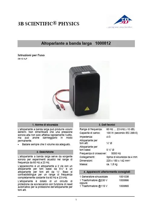
3B SCIENTIFIC ® PHYSICS1Istruzioni per l'uso09/15 ALFL'altoparlante a banda larga può produrre volumi estremi. Non dimenticare che una pressione sonora alta non solo affatica rapidamente l'udito, ma può anche danneggiarlo in modo permanente.∙ Badare sempre che il volume sia adeguato. L'altoparlante a banda larga serve da sorgente sonora per esperimenti acustici nel range di frequenza da 60 Hz a 23 Hz.L'apparecchio è un altoparlante a 2 vie con un altoparlante per toni bassi da 5½“ e un altoparlante per toni alti da ½“. Esso si contraddistingue per un range di frequenza completamente costante tra 60 Hz e 23 kHz. L'altoparlante è dotato di un circuitodi protezione da sovraccarico con funzione di reset automatico per la protezione dell'altoparlante per toni alti.Range di frequenza: 60 Hz … 23 kHz (-10 dB) Capacità di carico:100 W (secondo IEC 268-5)Impedenza: 4 Ω Altoparlante per toni alti: ½" Ø Altoparlante per toni bassi: 5 ½" Ø Frequenza di crossover: 5000 Hz Collegamenti: Spina di sicurezza da 4 mm Dimensioni: 225 x 150 x 142 mm 3Massa: ca. 1,8 kg 1 Generatore sinusoidale 1001038 1 Trasformatore @230 V 1000866 oppure1 Trasformatore @115 V10008653B Scientific GmbH ▪ Rudorffweg 8 ▪ 21031 Amburgo ▪ Germania ▪ Con riserva di modifiche tecniche © Copyright 2015 3B Scientific GmbH∙Non collegare l'altoparlante a una sorgente di tensione continua.Una superficie, che può vibrare leggermente, è inadatta all'altoparlante.∙ Posizionare l'altoparlante fondamentalmentesoltanto su superfici piane, fisse.∙ Non usare questo dispositivo vicinoall'acqua.∙ Badare che attraverso le aperture nell'internodell'alloggiamento non possa giungere nessun oggetto o liquido.∙ Non bloccare alcuna fessura di ventilazione.∙ Collegare l'altoparlante per toni bassi algeneratore sinusoidale.∙ Impostare tutti i regolatori del generatoresinusoidale su zero (battuta a sinistra).∙ Collegare il generatore sinusoidale alla retetramite il trasformatore.∙ Impostare i valori desiderati (frequenza,ampiezza) sul generatore sinusoidale.In caso di funzionamento prolungato nell'intervallo del massimo assorbimento di potenza, il circuito di protezione dell'altoparlante per toni alti può essere spento provvisoriamente. In questo caso non si presentano danneggiamenti.∙ Ridurre l'ampiezza, perché l'altoparlante pertoni alti si inserisca autonomamente.L'assistenza tecnica è necessaria nel caso in cui l'unità sia danneggiata, rovesciamento di liquidi od oggetti caduti nell'apparecchio, esposizione alla pioggia o all'umidità, anomalie di funzionamento o cadute dell'apparecchio.∙ Per l'assistenza tecnica rivolgersi apersonale qualificato.∙Pulire solo con uno strofinaccio asciutto.∙ Smaltire l'imballo presso i centri di raccolta e riciclaggio locali. ∙Non gettare l'apparecchio nei rifiuti domestici. Perlo smaltimento delle appare- cchiature elettriche, rispet- tare le disposizioni vigenti a livello locale.∙Non gettare le batterie esaurite nei rifiuti domestici. Rispettare le disposizioni legali locali (D: BattG; EU: 2006/66/EG).。

UT5300X+/UT5320R-SxA系列可编程耐压仪用户手册REV 22022.12感谢您购置优利德可编程耐压仪,为了确保正确使用本仪器,在操作仪器之前请仔细阅读手册,特别是有关“安全信息”部分。
如已阅读完手册,建议您将此手册妥善保管,以便在将来使用过程中进行查阅。
UNI-T优利德科技(中国)股份有限公司版权所有。
UNI-T产品受中国或其他国家专利权的保护,包括已取得或正在申请的专利。
本公司保留更改产品规格和价格的权利。
UNI-T保留所有权利。
许可软件产品由UNI-T及其子公司或提供商所有,受国家版权法及国际条约规定的保护。
本文中的信息将取代所有以前出版的资料中的信息。
UNI-T 是优利德科技(中国)股份有限公司(Uni-Trend Technology(China) Co.,Ltd)的注册商标。
仪器自购买之日起保修期壹年,在保修期内由于使用者操作不当而损坏仪器的,维修费及由于维修所引起的费用由用户承担,仪器由本公司负责终身维修。
如果原购买者自购该产品之日一年内,将该产品出售或转让给第三方,则保修期应为自原购买者从UNI-T或授权的UNI-T分销商购买该产品之日起一年内。
电源线及其他附件和保险丝等不受此保证的保护。
如果在适用的保修期内证明产品有缺陷,UNI-T可自行决定是修复有缺陷的产品且不收部件和人工费用,或用同等产品(由UNI-T决定)更换有缺陷的产品。
UNI-T作保修用途的部件、模块和更换产品可能是全新的,或者经修理具有相当于新产品的性能。
所有更换的部件、模块和产品将成为UNI-T的财产。
以下提到的“客户”是指据声明本保证所规定权利的个人或实体。
为获得本保证承诺的服务,“客户”必须在适用的保修期内向UNI-T通报缺陷,并为服务的履行做适当安排。
客户应负责将有缺陷的产品装箱并运送到UNI-T指定的维修中心,同时预付运费并提供原购买者的购买证明副本。
如果产品要运到UNI-T维修中心所在国范围的地点,UNI-T应支付向客户送返产品的费用。

Manual de usoÍndice de contenidosSímbolos (3)Información de seguridad (4)Componentes necesarios (5)Cable (5)Instrumento (5)Software (5)Pilas (5)Accesorios (6)Cómo funciona (7)Ajustes de Vulink (9)Retire la lengüeta de las pilas y presione el botón (9)Solución de problemas de conectividad de red (9)Añada otro instrumento y presione el botón (opcional). (10)Entender los LEDs (10)Registro con VuLink (12)Registros de VuLink (12)Registros de instrumentos (12)Uso de HydroVu (13)Uso de VuLink con VuSitu (14)Creación de alarmas (15)Uso de VuLink con un servidor FTP (16)Conexión de un instrumento de pulso a VuLink (18)Configuración de un instrumento de pulso con VuSitu (19)Añadir el instrumento a VuLink. (19)Configúrelo. (19)Entender las tarjetas SIM de VuLink (21)Actualización de VuLink (21)Controles (22)Especificaciones (23)Símbolos importantes en este manualSímbolos importantes en el productoEste símbolo indica información crítica de seguridad. Ignorar el texto que acompaña a este símbolo puedeprovocar lesiones o la muerte debido a una manipulación inadecuada.De acuerdo con la Directiva de Residuos de Aparatos Eléctricos y Electrónicos de la UE de 2005 y otras directivas posteriores, VuLink no debe desecharse junto con la basura doméstica convencional. Compruebe la normativa local sobre residuos electrónicos/eléctricos antes de deshacerse de un dispositivo VuLink.Directiva RAEE: Eliminación de VuLink al final de su vida útil PrecauciónUtilización correcta de VuLinkInstalación y sustitución de las pilasInstalación de la antena1 Cable2 Instrumento3 Software4 PilasCable robusto con sistema Twist-Lock Aqua TROLLVea los datos, gestione losinstrumentos, cree alarmas ymodifique la configuración deVuLink desde su navegador.Comuníquese con VuLink desde cualquierdispositivo móvil con Bluetooth y con laaplicación móvil VuSitu.Baro TROLLSoftware deHydroVuAplicación móvil VuSituNivel TROLL Rugged TROLLConecte VuLink con un instrumento Aqua TROLL, Baro TROLL,Level TROLL o Rugged TROLL.Con o sin ventilación.Antena de telefonía móvilDivisor de cables RuggedAdaptador universal decargaKit de montajeReferencia: 0043630Referencia: 0095500 (con ventilación)Referencia: 0085840 (sin ventilación)Referencia: 0101000Referencia: 0095570La antena de telefonía móvil permite una fuerte conectividad a la red móvil.Con el divisor de cable Rugged, puede conectar hasta 8 instrumentos con VuLink.Para acoplar instrumentos de medición de flujo y dispositivos que no disponene de un conector Twist-Lock, utilice el adaptador universal de carga.El kit de montaje permite fijar VuLink a un poste, una pared u otra estructura.123MosquetónDispositivo de telemetría VuLinkInstrumentoVuLink cuelga de la parte superior de un pozo con su mosquetón desmontable.VuLink aporta energía a los instrumentos de monitorización, transmite los datos a la nube y le notifica cuando es necesario realizar algún mantenimiento.Un instrumento de In-Situ mide la calidad y/o el nivel del agua.Coloque la antena y conecte un instrumento.Después de conectar la antena externa o de a bordo y elinstrumento, siga las instrucciones de las siguientes páginas deesta guía de inicio rápido.24telemetría.Visite la página y cree una cuenta.Haga clic en el enlace de la página de telemetría en el menú a la izquierda de la página. A continuación, haga clic en Añadir un VuLink .Abra su cámara web y escanee el código QR en su dispositivo, o escriba el código de registro en el campo disponible.o c l i cPulse en 2G para modificar la configuración de red deVuLink. Pulse enGuardar .VuLink debería ahora ser capaz de conectarse a una red y sincronizarse con HydroVu.Presione el botón Todos los ajustes en la parte inferior dela pantalla.Pulse en Red móvil en lapantalla de Ajustes.Retire la tapa de las pilas girándola en sentido antihorario y tirando hacia abajo.Asegúrese de que la antena está bien colocada antes de continuar.Presione el botón. Todos los LEDs se encienden. A continuación, cada LED cambia de color en función del estado del dispositivo.Retire la lengüeta amarilla para permitir que la corriente pase a través de las pilas. Vuelva a colocar la tapa.VuLink funciona con los instrumentos Aqua TROLL, Level TROLL, Baro TROLL y Rugged TROLL. Siga los siguientes pasos para comenzar a transmitir datos.5 Retire la lengüeta de las pilas y presione el botón.Solución de problemas de conectividad de redVuLink se conecta al nuevo instrumento y a la red de datos.Desconecte el instrumento de VuLink. Añada otro. Presione el botón.VuLink se conecta a HydroVu o a un servidor FTP .Todos los LEDs indican el estado actual del dispositivo. Consulte la sección siguientepara obtener más detalles.Entender los LEDsRojo fijo Verde fijoVerde intermitenteRojo intermitente La carga de la batería es de al menos el 75%.La carga de la batería entre el 25% y el 50%.La carga de la batería está entre el 50% y el 75%.La carga de la batería inferior al 25%.Estado de la batería7 Añada otro instrumento y presione el botón (opcional).Parpadeo rojo y verdeUn LED rojo y verde intermitente indica un problema con las pilas. No haga uso de VuLink en estas condiciones. Compruebe las pilas y vuelva a colocarlas si es necesario.Rojo fijoVerde fijoVerde intermitenteRojo intermitenteBuscando un instrumentoNuevo instrumento no encontradoConectado al instrumentoNo hay instrumentos conectados a VuLinkRojo fijoRojo intermitenteVerde fijoVerde intermitenteIntentando conectarse a la redConectado a la redNo se puede conectar a la redLa antena de VuLink está desconectada o VuLink no puede localizar una red móvil.Rojo fijoVerde fijoAzul fijoAzul intermitenteVerde intermitenteRojo intermitenteDispositivo no reclamadoCarga exitosaConectado por BluetoothListo para conectarConectando y cargando datos a HydroVuFallo en la conexión con Estado de la conexión del instrumentoEstado de la conexión a la redEstado de la conexión con la nubeEstado de la conexión BluetoothProgramar un reg-istro en VuLink conla aplicación móvil VuSitu.un registroen el instru-con VuSitu.archivos de registro con Registros de VuLinkRegistros de instrumentos112Ver sus datos en HydroVu.Crear y editar paneles de controlGestionar alarmasConfigurar notificacionesVer ubicacionesConfigurar dispositivos detelemetríaCargar datosEditar parámetros calculadosGestionar usuariosVer sus datosOpciones del menú de la barra lateral/Páginas de HydroVuPantalla del dispositivo de telemetría conectadoPulse en la opciónConfiguración del menú y luego elija Alarmas en tiempo real .Para crear una alarma, pulse en Añadir una alarma entiempo real.Seleccione el parámetro que debe activar la alarma y establezca los límites.Conéctese a VuLink con laaplicación móvil VuSitu.Introduzca sus credenciales FTP . A continuación, pulse en Probar y Guardar .VuLink prueba la conexión con el aplicación muestra los resultados de la prueba.Pulse en Todos los ajustes .Seleccione el Servicio de telemetría en la nube .a bdgPulse en el botón de radio junto a FTP .cefPuede configurar VuLink para cargar los datos en un servidor FTP a través de VuSitu. Tenga preparado el nombre del servidor FTP Recuperación de datosAcceda a la pantalla del Servicio de telemetría en la nube como se muestra arriba.Introduzca una fecha y hora de inicio, o un número de registro de inicio.Pulse en Inicio .Pulse en Cargar datos faltantes .Lea el mensaje emergente sobre los gastos de datos. Pulse en Enviar datos si desea continuar.Si la carga se produce con éxito, VuSitu muestra unaconfirmación.Componentes necesariosCableado con el adaptador universal de carga (LBUA)• Cable Rugged con bloqueo Twist-Lock con un extremo pelado y estañado • Adaptador universal de carga (LBUA)• Cable (del LBUA al instrumento de pulso)• Instrumento de pulso • VuLinkLeyenda del cable RuggedColor del cableSeñal Marrón Salida del pulsoNegro TierraRojo Alimentación (opcional)Azul Sin usar Verde Sin usarBlancoSin usarConecte el extremo con el Twist-Lock de un cable Rugged a VuLink.Conecte los hilos marrón y negro del otro extremo del cable Rugged al adaptador universal de carga.Corte los cuatro cables sin uso. Pase los cables desde el otroextremo del LBUA hasta elinstrumento de pulso.A VuLinkHasta el pulso instrumentoAñadir el instrumento a VuLink.Configúrelo.Inicie VuSitu y conéctese a VuLink.Conecte el instrumento a VuLink con un cable. Presione en el botón Añadirde VuSitu.VuSitu muestra un mensaje de confirmación. Pulse en OK paradescartarlo.Pulse en el menúdesplegablede InstrumentosConectados .Pulse en el menúdesplegablede Instrumentos Conectados .Pulse en Añadir nuevo .Seleccione el botón de radio del instrumento medidor de pulso .Pulse en el instrumento.Seleccione la frecuencia baja o alta.Frecuencia baja: Elija uno de los tres parámetros integrados o cree un parámetro personalizado.Añada pluviómetros y otros dispositivos de pulso a VuLink con la configuración de pulso de VuSitu.engranaje junto al campo dela unidad para seleccionar unaIntroduzca un valor mínimo ymáximo.Introduzca una frecuenciamínima y máxima en hercios.Pulse enGuardarparaconfirmar la configuracióndel instrumento medidor deIntroduzca el valor de un pulsoen las unidades seleccionadas.Pulse en Guardar. VuSitumuestra el mensaje de"Guardando".VuSitu muestra el mensaje de"Guardando".Alta frecuencia: SeleccioneAlta Frecuencia y elija unparámetro y una unidad.Tarjeta SIM externaSIM integradaVuLink trata de utilizar una tarjeta SIM externa para todas las comunicaciones si hay una. Si la comunicación a través de la SIM externa falla, VuLink utiliza en su lugar la tarjeta SIM integrada.Si no hay una tarjeta SIM externa, VuLink utiliza su SIM integrada para todas las comunicaciones.21Mosquetón 2Estado de la conexión Bluetooth 3Estado de la batería 4Estado de la conexión 5Estado de la conexión a la red 6Estado de la conexión con la nube 7Antena 8 Botón de encendido 3Pilas Compatible con 3 x celdas D (1,5V - 3,6V) alcalina/Li-SOCl2 [cloruro de litio y tionilo]/Li-MnO2 [dióxido de litio y manganeso]Tiempo de funcionamiento(informe de 24 horas,batería de Li-MnO2)Hasta 12 años*.Tiempo de funcionamiento(informe de 24 horas,batería alcalina)Hasta 3 años*Precisión del reloj Menos de 1 minuto de desviación al año con capacidad de sincronización con la horafacilitada por la red para una precisión de +/- 1 segundoTipo de red4G LTE Categoría M1 (LTE-M) / NB-IoT (Narrowband) con opción a 2GBandas de radio LTE Global - B1(2100), B2(1900), B3(1800), B4(AWS 1700), B5(850), B8(900), B12(700),B13(700), B18(800), B19(800), B20(800), B28(700)Protocolos HTTPS (HydroVu), SMS (alarmas)Proveedor de datos Itinerancia global gratuita** integrada (consulte el anexo de la lista de redes para obtener más detalles: /VuLinkNetworks), ranura adicional de 4FF para soporte de SIM de tercerosAntena Conector SMA-MGPS Precisión de hasta 3 m, antena incorporadaFormato de archivo (sinHydroVu)CSVConfiguración remota CompatibleLongitud total19.1”Diámetro 1.85”Peso2,2 libras/1,0 kg (con pilas alcalinas y mosquetón incluidos, sin incluir la antena)Materiales Ryton (carcasa), PVC (tapa de las pilas), titanio (conector Twistlock, cáncamo), acero inoxidable 316 (mosquetón), silicona (tapa del teclado), latón (conector de antena SMA), policarbonato (etiqueta), Viton (juntas tóricas)Temperatura dealmacenamiento-20°C a 60°CTemperatura defuncionamiento-20°C a 50°C (Li-SOCl2/Li-MnO2), 5°C - 40°C (Alcalina)Protección contra lapenetración Dispositivo: IP68 Sistema: Hasta IP68 según especificación de la antenaProtocolos Modbus sobre RS-485, SDI-12, Pulso de baja/alta frecuencia (máximo 40 khz)Conectores 1 "Twistlock" In-Situ (admite varios instrumentos a través de un divisor de cable Rugged,TROLL Net Hub o un adaptador universal de carga)Conexiones simultáneas Hasta 8 instrumentos (máximo total de 75mA dispuestos a los instrumentos conectados a16V)Ventilación Incorporada en todos los modelos, no requiere desecanteCompensaciónbarométrica Incorporada en todos los modelos para la compensación automática de las lecturas de nivel Precisión del barómetro+/- 1 hPaAlarmas Configurables en función de las lecturas de los instrumentos y de los parámetros deldispositivoBotón de encendido Máximo total de 75mA dispuestos entre los instrumentos conectados a 16V (destinadosnormalmente a alimentar un solo instrumento)Configuración inalámbrica Compatible con Bluetooth Low EnergyTasa de registro De 1 minuto a 7 díasTasa de transmisión De 5 minutos a 7 díasMemoria512 MB (soldados a la placa de circuito)Potencia máxima de salidadel transmisor Todas las bandas LTE FDD: +23 dBm +/- 1dB (conducido)GSM900: +32,5 dBm +/- 1dB GSM1800: +29,5 dBm +/- 1dB (conducido) EGPRS900: +27,0 dBm +/- 1dB EDGE1800: +26,0 dBm +/- 1dB (conducido) Bluetooth: +5,5 dBm +/- 0,35 dB (EIRP)。

—BROCHUREABB Ability™ Symphony® Plus Thin WebClient2A B B A B I LIT Y S Y M PH O N Y PLU S TH I N W EB CL I ENT —ThinWebClientKeeping tabs on a plant’s status is crucial to the operation and efficiency of the plant. Not only should operators be aware of the plant data, the plant management needs to be informed in order to make business decisions. However, plant data must be collected or analyzed at a specified time otherwiseit often interrupts operator activity and disrupts work places.Using tools built in to ABB Ability Symphony Plus Operations, prescribed reports can be exportedto quickly analyze the state of the plant to make preventative or reactive actions. The Symphony Plus software provides easy configuration of displays, reports and the powerful Historian system.Shifting to digital solutions, Symphony Plus Thin WebClient allows plant management to tap intodata on the Webserver for analysis as frequent as necessary without the need for software. Simply connect to the plant server via Microsoft Internet Explorer and receive reports in an easy to read format. Navigator ClientSymphony Plus’ integrated information management capability provides support at every organizational level to improve efficiency and profitability. Symphony Plus enables viewing of real-time data and historical information simultaneously in one display. Symphony Plus provides the data collection and analytical tools necessary for plants who make intensive data analysis in their operations.Thin WebClient user interfaceThe Thin WebClient uses HTTPS protocol, ensuring Report publishingThin WebClient pushes data to the WebServerfor use in remote monitoring. It automatically publishes graphics that are predetermined within the Symphony Plus system, increasing efficiency and consistency of reporting. Each report can be updated from anywhere by the Thin WebClient without software. Example reports include:• Dynamic trend displays• Symphony Plus Graphics History display• S+ Operations graphics• Event view and history list, including– Event Grid– Event Hitlist– Event Count– Event TaglistMobile report compatibilityThe Thin WebClient provides easy-to-read documentation of:• Trend Displays• History Reports• History Graphics• History Alarm and EventsThe ValueBringing data from the plant to a mobile device has never been easier. With a smartphone, tablet, or laptop, Thin WebClient allows managers to see the status of their plant to make informed decisions remotely. Connect to the web portal from anywhere and gain access to a variety of reports via a secure HTTPS connection to monitor plant data in detail on the go.Thin WebClient• Access data and reports remotely witha secure connection at any frequencywithout disrupting operator workflow.• Predefine data analysis for quick, easy-to-read reporting on all devices.• Use an HTTPS connection to the plant’sWebServer for increase security.A B B A B I LIT Y S Y M PH O N Y PLU S TH I N W EB CL I ENT32V A A 009449 P o w e r G e n e r a t i o n a n d W a t e r 1117—/symphonyplus /powergeneration /water—Note:We reserve the right to make technical changes to the products or modify the contents of this document without prior notice. With regard to purchase orders, the agreed particulars shall prevail. ABB does not assume any responsibility for any errors or incomplete information in this document.We reserve all rights to this document and the items and images it contains. The reproduction, disclosure to third parties or the use of the content of this document – including parts thereof – are prohibited without ABB’s prior written permission.Copyright© 2017 ABB All rights reservedABB Ability is a trademark of ABB.Symphony and Symphony Plus are registered or pending trademarks of ABB.All rights to other trademarks reside with their respective owners.—S+ Office Thin WebClient Use casesUse it as an Annunciator PanelConnect the web portal to a display in the control room and use it as a real-time summary reference point for the team.• An interactive blackboard to share data with the team• Check alarms, specific parameter, graphics at a glance.• No need to dedicate a full client for the same scope – Light investment– Light configuration effortEasy sharing KPI and reportingShare real-time production KPIs in the easiest and smoother way with management.• No need to install any software• Possible to share data in the intranet • Monitor data everywhereQuick and mobile data access for maintenance Any maintenance operator can quickly access to his device and check real-time data from the web portal on the go.• Historic and real-time data always in your availability • Flexible and time saving•Secure, because data are in read only mode。
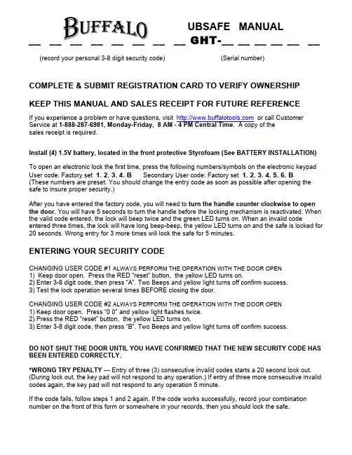
UBSAFE MANUAL__ __ __ __ __ __ __ __ GHT-__ __ __ __ __ __ (record your personal 3-8 digit security code) (Serial number)COMPLETE & SUBMIT REGISTRATION CARD TO VERIFY OWNERSHIP KEEP THIS MANUAL AND SALES RECEIPT FOR FUTURE REFERENCEIf you experience a problem or have questions, visit or call Customer Service at 1-888-287-6981, Monday-Friday, 8 AM - 4 PM Central Time. A copy of thesales receipt is required.Install (4) 1.5V battery, located in the front protective Styrofoam (See BATTERY INSTALLATION) To open an electronic lock the first time, press the following numbers/symbols on the electronic keypad User code: Factory set 1. 2. 3. 4. B Secondary User code: Factory set 1. 2. 3. 4. 5. 6. B(These numbers are preset. You should change the entry code as soon as possible after opening the safe to insure proper security.)After you have entered the factory code, you will need to turn the handle counter clockwise to open the door. You will have 5 seconds to turn the handle before the locking mechanism is reactivated. When the valid code entered, the lock will beep twice and the green LED turns on. When an invalid code entered three times, the lock will have long beep-beep, the yellow LED turns on and the safe is locked for 20 seconds. Wrong entry for 3 more times will lock the safe for 5 minutes.ENTERING YOUR SECURITY CODECHANGING USER CODE #1 ALWAYS PERFORM THE OPERATION WITH THE DOOR OPEN1) Keep door open. Press the RED “reset” button, the yellow LED turns on.2) Enter 3-8 digit code, then press “A”. Two Beeps and yellow light turns off confirm success.3) Test the lock operation several times BEFORE closing the door.CHANGING USER CODE #2 ALWAYS PERFORM THE OPERATION WITH THE DOOR OPEN1) Keep door open. Press “0 0” and yellow light flashes twice.2) Press the RED “reset” button, the yellow LED turns on.3) Enter 3-8 digit code, then press “B”. Two Beeps and yellow light turns off confirm success.DO NOT SHUT THE DOOR UNTIL YOU HAVE CONFIRMED THAT THE NEW SECURITY CODE HAS BEEN ENTERED CORRECTLY.*WRONG TRY PENALTY --- Entry of three (3) consecutive invalid codes starts a 20 second lock out. (During lock out, the key pad will not respond to any operation.) If entry of three more consecutive invalid codes again, the key pad will not respond to any operation 5 minute.If the code fails, follow steps 1 and 2 again. If the code works successfully, record your combination number on the front of this form or somewhere in your records, then you should lock the safe.Size: 7''(H) x 48''(W) x 28''(D) / 3 Cubic Feet Of Storage / 2.0mm thickNo Fire Rating2 x 1/2" Steel Bolts100 Pound Max Weight CapacityIncludes (4) 1.5V AA batteries (Batteries are installed here) BATTERY INSTALLATIONThis lock requires (4) 1.5V AA batteries. Under normal use, batteries will last about 1 year. When the battery is low and you press a button on the keypad, a red light will come on warning you that the battery is low.To test the battery, enter your security code. If the batteries are low the red light will come on momentarily. To replace the battery, remove the cover by pressing the tab and turning the cover as shown in the illustration above. Replace the old battery and attach the cover back in place.TROUBLE KEY/OVERRIDE KEYyou have forgotten or lost your security code. Please record the numberof your key in a safe location in the event the key needs to be replacedin the future. To open the safe using the trouble key, follow the steps:1. Remove the cover by taking off the cover as shown in theillustration.2. Insert the key in the key hole and turn clockwise 15-20 degrees (until stopped) in order to unlockthe safe, then rotate the knob.3. Keep the door open until you have entered a new security code. Before entering your newsecurity code, turn the key back and remove the key and put the cover back in place.4. Enter your new security code. (DO NOT STORE KEY IN SAFE)REPLACEMENT TROUBLE KEY/OVERRIDE KEYVerification of ownership is required in order to receive replacement key. Contact Customer Service at 1-888-287-6981 to verify registration, then complete the Replacement Form, along with required Service Fees. The Replacement Form must include the Serial Number and Lock number, andbe notarized by a non-family member.。


GSM_U2 Library for G-4511, G-4513 seriesUser’s Manual V1.0High Quality, Industrial Data Acquisition, and Control ProductsWarrantyAll products manufactured by ICP DAS are warranted against defective materials for a period of one year from the date of delivery to the original purchaser.WarningICP DAS assumes no liability for damages consequent to the use of this product. ICP DAS reserves the right to change this manual at any time without notice. The information furnished by ICP DAS is believed to be accurate and reliable. However, no responsibility is assumed by ICP DAS for its use, or for any infringements of patents or other rights of third parties resulting from its use.CopyrightCopyright 2014 by ICP DAS CO., LTD. All rights reserved worldwide.TrademarkThe names used for identification only may be registered trademarks of their respective companies.Contact usTable of Contents1. Introduction (1)1.1 2G/3G and PAC Embedded Controller (1)1.2 Design Flowchart (2)2. GSM_U2 Library (3)2.1 Data Structure Define (3)2.2 SYSTEM Function (5)2.2.1 GM_SYS_GetLibVersion (6)2.2.2 GM_SYS_GetLibDate (7)2.2.3 GM_SYS_InitModem (8)2.2.4 GM_SYS_CloseModem (9)2.2.5 GM_SYS_CheckModemStatus (10)2.2.6 GM_SYS_CheckCmdStatus (11)2.2.7 GM_SYS_CheckSignal (12)2.2.8 GM_SYS_CheckReg (13)2.2.9 GM_SYS_EnableNITZ (14)2.2.10 GM_SYS_NITZUpdateRTC (15)2.2.11 GM_SYS_CheckNITZ (16)2.3 SMS Function (17)2.3.1 GM_SMS_SendMsg (18)2.3.2 GM_SMS_GetNewMsg (19)2.4 3G / GPRS Data Transmission Function (20)2.4.1 GM_NET_SetNet (21)2.4.2 GM_NET_InstallLink (22)2.4.3 GM_NET_CloseNet (23)2.4.4 GM_NET_GetIP (24)2.4.5 GM_NET_CloseLink (25)2.4.6 GM_NET_GetLinkStatus (26)2.4.7 GM_NET_Send (27)2.4.8 GM_NET_GetNewPacket (28)3. Revision History (29)1. Introduction1.1 2G/3G and PAC Embedded Controller2G/3G is a service that allows information to be sent and received across a mobile telephone network. It supports CSD (Circuit Switched Data), SMS (Short Message Service) and GPRS (General Packet Radio Service). GPRS is NOT related to GPS (the Global Positioning System), a similar acronym that is often used in mobile contexts. 2G/3G offers instant connections whereby information can be sent or received immediately as the need arises, subject to radio coverage. This is why 2G/3G users are sometimes referred to be as being "always connected". Immediacy is one of the advantages of 2G/3G (and SMS) when compared to Circuit Switched Data. High immediacy is a very important feature for time critical applications.ICP DAS provides the 2G/3G library for PAC embedded controller. The library is an easy way to applying the 2G/3G service in the embedded controller. Otherwise, ICP DAS supports many IO modules and GPS modules for users. Therefore, there are many application architectures to apply in the system. Or users can integrate other controller system with 2G/3G library. The follows is a standard application architecture.1.2 Design FlowchartSMS Design Flowchart GPRS Design Flowchart2. GSM_U2 Library2.1 Data Structure DefineThere are some data structure that is useful when you program with GSM_U2 library. SMS://-- structure for sending/reading SMStypedef struct STRENCODE_MSG{char phoneNumber[30]; //phone numberchar time[20]; //sms_time_stampchar msg[161]; //message's contentunsigned char dataLen; //Message's length//Max length: 7-bit=160 words, UCS2=70 words(140 bytes) char mode; //encode style: 0=GSM_7BIT, 8=GSM_UCS2(uni-code)} strEncode_Msg;GPRS://-- structure for reading GPRS socketstypedef struct GPRSDATA{char data[1500]; //dataint dataLen; //data lengthchar fromIP[16]; //IP of the server,000.000.000.000 and '0x00', total 16 byte unsigned int port; //TCP/UDP port of the serverint link; //data of link[n]} GPRSData;//-- structure for setting networktypedef struct NET_PROFILE{char APN[60]; //APN for network provided by your cellular providerchar user[32]; //username for network provided by your cellular providerchar pw[32]; //password for network provided by your cellular providerchar DnsServerIP[16]; //The most basic task of DNS is to translate hostnames//such as to IP address such as 96.9.41.131. } NetProfile;SYSTEM://-- structure for setting system parameterstypedef struct SYS_PROFILE{char PINCode[5]; //The pin code of SIM card, ex: "0000"int modemPort; //modem port number.int hardware; //hardware type. 0: G-4511、G-4513 series, 1: G-4500}SYSProfile;Tips & Warnings1. The GSM_U2 library needs OS7_COM.lib. Please include it.2. The speed of GPRS is less than 1 packet / 1 second.3. The GSM_U2 library needs the Timer that installed by “InstallUserTimer()”.Please don’t collide with it.2.2 SYSTEM Function2.2.1 GM_SYS_GetLibVersionGet library version.ParametersNoneReturn valuesVersion format = A.BC2.2.2 GM_SYS_GetLibDateGet library date.ParameterslibDatea string of lib. date, format="Jul 21 2014" Return valuesNone2.2.3 GM_SYS_InitModemInitialize Modem.**must use GM_SYS_CheckModemStatus() to check modem status laterParameterssysProfileset system profileReturn valuesGM_NOERROR:successGM_COMERROR:comport errorGM_INITERROR:init fail error2.2.4 GM_SYS_CloseModemClose the modem.**Please call GM_SYS_InitModem() to wake up modem after using GM_SYS_CloseModem(1) to shut down the modem.Parametersmode0:close modem, but maintain it power on1:close modem and set it power offReturn valuesGM_NOERROR:no errorGM_CMDERROR:command error2.2.5 GM_SYS_CheckModemStatusCheck modem status, and suggest you check it in your loop every time.ParametersNoneReturn valuesGM_NOERROR:modem register success, can serviceGM_NOREG:modem not registered, can't service2.2.6 GM_SYS_CheckCmdStatusGet the status of the command you sent.ParametersNoneReturn valuesGM_BUSY:modem busy, you can't send other command GM_NOERROR:successGM_TIMEOUT:time outGM_CMDERROR:command errorOther:please refer to error codes of GSM_U2.h2.2.7 GM_SYS_CheckSignalCheck signal quality.ParametersNoneReturn valuessignal quality0 -113 dBm or less1 -111 dBm2...30 -109... -53 dBm31 -51 dBm or greaterCheck register.ParametersNoneReturn valuesNoneExampleRegister flag0:not registered1:registered, home network2:not registered, and searching...3:registration denied4:unknown5:registered, roamingEnable NITZ function.**NITZ function can auto-adjust RTC of the system at the moment of the modem registering to GSM system.**Please call “GM_SYS_NITZUpdateRTC” to update RTC after GM_SYS_EnableNITZ(1).Parametersnitz0:disable1:enableReturn valuesNone2.2.10 GM_SYS_NITZUpdateRTCUpdate the RTC of the System by NITZ.**Notice: this function will disable all 3G/GSM function about 1~2 minutes.**Please use this function after you stop all 3G/GSM functionParametersNoneReturn valuesNone2.2.11 GM_SYS_CheckNITZCheck the status of NITZ.ParametersNoneReturn values0:fail to update RTC1:success2:updating2.3 SMS Function2.3.1 GM_SMS_SendMsgSend a message.**must use "GM_SYS_CheckCmdStatus()" to check status laterParametersstrMsgthe message that will be sent.Return valuesGM_NOERROR:no errorGM_NOREG:not registered, or can't serviceGM_BUSY:modem busy2.3.2 GM_SMS_GetNewMsgGet a new sms message.Parametersmsgnew sms message Return values0:no new message1:new message coming2.4 3G / GPRS Data Transmission Function2.4.1 GM_NET_SetNetSet Net profile data.ParametersnetProfileNet profile dataReturn valuesGM_NOERROR:no errorGM_CMDERROR:command errorBuilt TCP/UDP link.Parametersnlink number (0~6)3G (G-4513 series):0~62G (G-4511 series):0tcpclient type, tcp=1 for TCP client ; tcp=0 for UDP clientserverIPIP or Domain name of the server, ex: "61.111.222.333", ""serverPortTCP/UDP Port of the server (1~65535), ex: 1234ReturnGM_NOERROR:correct parameter to install TCP/UDP linkGM_CMDERROR:command errorClose Network.ParametersNoneReturn valuesGM_NOERROR:no errorGM_CMDERROR:command errorGM_BUSY:modem busy2.4.4 GM_NET_GetIPGet local IP.ParametersipaddrIP string, format: char ipaddr[16]; Return valuesNone2.4.5 GM_NET_CloseLinkClose client link[n].Parametersn3G (G-4513 series):0~62G (G-4511 series):0Return valuesGM_NOERROR:no errorGM_CMDERROR:command errorGM_BUSY:modem busy2.4.6 GM_NET_GetLinkStatusGet status of Link[n].Parametersn3G (G-4513 series):0~62G (G-4511 series):0 Return values0:not link1:linked2.4.7 GM_NET_SendSend a packet.**must use "GM_SYS_CheckCmdStatus()" to check status laterParameterslinklink number3G (G-4513 series):0~62G (G-4511 series):0datadata that will be sentdataLendata length, Max.=1000Return valuesGM_NOERROR:no errorGM_CMDERROR:command errorGM_BUSY:modem busy2.4.8 GM_NET_GetNewPacketGet the new packet.ParametersgprsDatanew data packetReturn values0:no new packet1:new packet coming3. Revision History。
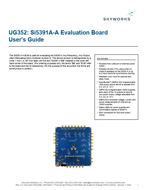
UG352: Si5391A-A Evaluation Board User's GuideThe Si5391A-A-EVB is used for evaluating the Si5391A Any-Frequency, Any-Output,Jitter-Attenuating Clock Multiplier revision D. The device revision is distinguished by a white 1 inch x 0.187 inch label with the text “SI5391-A-EB” installed in the lower left hand corner of the board. (For ordering purposes only, the terms “EB” and “EVB” refer to the board and the kit respectively. For the purpose of this document, the terms are synonymous in context.)EVB FEATURES•Powered from USB port or external power supply.•Onboard 48 MHz XTAL allows free-run mode of operation on the Si5391A or up to 3 input clocks for synchronous clocking.•Feedback clock input for optional zero delay mode.•ClockBuilder ® (CBPro) GUI programmable VDD supply allows device to operate from 3.3, 2.5, or 1.8 V.•CBPro GUI programmable VDDO supplies allow each of the 10 outputs to have its own power supply voltage selectable from 3.3, 2.5, or 1.8 V.•CBPro GUI-controlled voltage, current, and power measurements of VDD and all VDDO supplies.•Status LEDs for power supplies and control/status signals of Si5391A.•SMA connectors for input and output clocks.UG352: Si5391A-A Evaluation Board User's Guide • Functional Block Diagram1. Functional Block DiagramBelow is a functional block diagram of the Si5391A-A-EB. This evaluation board can be connected to a PC via the main USB connector for programming, control, and monitoring. See Section 3. Quick Start or Section 8. Installing ClockBuilder Pro Desktop Software for more information.Figure 1.1. Si5391A-A EB Functional Block DiagramUG352: Si5391A-A Evaluation Board User's Guide • Si5391A-A-EVB Support Documentation and ClockBuilder Pro Software2. Si5391A-A-EVB Support Documentation and ClockBuilder Pro SoftwareAll Si5391A-A-EVB schematics, BOMs, User’s Guides, and software can be found online at the following link: https:///en/Products/TimingUG352: Si5391A-A Evaluation Board User's Guide • Quick Start3. Quick Start1.Install ClockBuilder Pro desktop software from https:///en/application-pages/clockbuilder-pro-software.2.Connect a USB cable from Si5391A-A-EB to the PC where the software was installed.3.Confirm jumpers are installed as shown in Table4.1 Si5391A-A-EB Jumper Defaults on page5.unch the ClockBuilder Pro Software.5.You can use ClockBuilder Pro to create, download, and run a frequency plan on the Si5391A-A-EB.6.For the Si5391A data sheet, go to https:///en/Products/Timing.UG352: Si5391A-A Evaluation Board User's Guide • Jumper Defaults4. Jumper DefaultsTable 4.1. Si5391A-A-EB Jumper DefaultsUG352: Si5391A-A Evaluation Board User's Guide • Staus LEDs5. Staus LEDsTable 5.1. Si5391A-A-EB Status LEDsD27, D22, and D26 are illuminated when USB +5 V, Si5391A +3.3 V, and Si5391A VDD supply voltages, respectively, are present. D25, D21, and D24 are status LEDs showing on-board MCU activity.Figure 5.1. Status LEDsUG352: Si5391A-A Evaluation Board User's Guide • Clock Input Circuits (INx/INxB and FB_IN/FB_INB)6. Clock Input Circuits (INx/INxB and FB_IN/FB_INB)The Si5391A-A-EB has eight SMA connectors (IN0/IN0B–IN2/IN3B and FB_IN/FB_INB) for receiving external clock signals. All input clocks are terminated as shown in figure below. Note input clocks are ac-coupled and 50 Ω terminated. This represents four differential input clock pairs. Single-ended clocks can be used by appropriately driving one side of the differential pair with a single-ended clock. For details on how to configure inputs as single-ended, please refer to the Si5391 Data Sheet.Figure 6.1. Input Clock Termination CircuitUG352: Si5391A-A Evaluation Board User's Guide • Clock Output Circuits (OUTx/OUTxB)7. Clock Output Circuits (OUTx/OUTxB)Each of the twenty-four output drivers (12 differential pairs) is ac-coupled to its respective SMA connector. The output clock termination circuit is shown in the figure below. The output signal will have no dc bias. If dc coupling is required, the ac coupling capacitors can be replaced with a resistor of appropriate value. The Si5391A-A-EVB provides pads for optional output termination resistors and/or low frequency capacitors. Note that components with schematic “NI” designation are not normally populated on the Si5391A-A-EB and provide locations on the PCB for optional dc/ac terminations by the end user.Figure 7.1. OUtput Clock Termination CircuitUG352: Si5391A-A Evaluation Board User's Guide • Installing ClockBuilder Pro Desktop Software8. Installing ClockBuilder Pro Desktop SoftwareTo install the CBPro software on any Windows 7 or Windows 10 PC, go to https:///en/application-pages/clock-builder-pro-software and download ClockBuilder Pro software.Installation instructions and User’s Guide for ClockBuilder Pro can be found at the download link shown above. Follow the instructions as indicated.UG352: Si5391A-A Evaluation Board User's Guide • Using the Si5391A-A-EVB9. Using the Si5391A-A-EVB9.1 Connecting the EVB to Your Host PCOnce ClockBuilder Pro software is installed, connect to the evaluation board with a USB cable as shown below.Figure 9.1. EVB Connection Diagram9.2 Additional Power SuppliesAlthough additional power (besides the power supplied by the host PC’s USB port) is not needed for most configurations, two additional +5 VDC power supplies (MAIN and AUX) can be connected to J33 and J34 (located on the bottom of the board, near the USB connector). Refer to the Si5391A-A-EB schematic for details.The Si5391A-A-EB comes preconfigured with jumpers installed at JP15 and JP16 (pins 1-2 in both cases) in order to select “USB”. These jumpers, together with the components installed, configure the evaluation board to obtain all +5 V power solely through the main USB connector at J37. This setup is the default configuration and should normally be sufficient.The figure below shows the correct installation of the jumper shunts at JP15 and JP16 for default or standard operation.Figure 9.2. JP15-JP16 Standard Jumper Shunt InstallationNote: Some early versions of the 64-pin Si534x-EBs may have the silkscreen text at JP15-JP16 reversed regarding EXT and USB, i.e., USB EXT instead of EXT USB. Regardless, the correct installation of the jumper shunts for default or standard operation is on the right hand side as read and viewed in the figure above.The general guidelines for single USB power supply operation are listed below:•Use either a USB 3.0 or USB 2.0 port. These ports are specified to supply 900 mA and 500 mA respectively at +5 V.•If you are working with a USB 2.0 port and you are current limited, turn off enough DUT output voltage regulators to drop the total DUT current ≤ 470 mA. (Note: USB 2.0 ports may supply > 500 mA. Provided the nominal +5 V drops gracefully by less than 10%, the EVB will still work.)•If you are working with a USB 2.0 and you are current limited and need all output clock drivers enabled, re-configure the EB to drive the DUT output voltage regulators from an external +5 V power supply as follows:•Connect external +5 V power supply to terminal block J33 on the back side of the PCB.•Move the jumper at JP15 from pins 1-2 USB to pins 2-3 EXT.9.3 Overview of ClockBuilder Pro ApplicationsNote: The following instructions and screen captures may vary slightly depending on your version of ClockBuilder Pro. The ClockBuilder Pro installer will install two main applications:Figure 9.3. Application #1: ClockBuilder Pro WizardUse the CBPro Wizard to:•Review or edit an existing design•Export: Create in-system programming•Create a new designFigure 9.4. Application #2: EVB GUIUse the EVB to:•Download configuration to EVB's DUT (Si5391A)•Control the EVB's regulators•Monitor voltage, current, power on the EVB9.4 Common ClockBuilder Pro Work Flow ScenariosThere are three common workflow scenarios when using CBPro and the Si5391A-A-EVB. These workflow scenarios are:•Workflow Scenario #1: Testing a Skyworks-Created Default Configuration•Workflow Scenario #2: Modifying the Default Skyworks-Created Device Configuration•Workflow Scenario #3: Testing a User-Created Device Configuration EachEach workflow is described in more detail in the following subsections.9.5 Workflow Scenario #1: Testing a Skyworks-Created Default ConfigurationThe flow for using the EVB GUI to initialize and control a device on the EVB is as follows.Once the PC and EVB are connected, launch ClockBuilder Pro by clicking on this icon on your PC’s desktop.Figure 9.5. ClockBuilder Pro Desktop IconIf an EVB is detected, click on the “Open Default Plan” button on the Wizard’s main menu. CBPro automatically detects the EVB and device type.Figure 9.6. Open Default PlanOnce you open the default plan (based on your EVB model number), a popup will appear.Figure 9.7. Write Design to EVB DialogSelect “Yes” to write the default plan to the Si5391A device mounted on your EVB. This ensures the device is completely reconfigured per the Skyworks default plan for the DUT type mounted on the EVB.Figure 9.8. Writing Design StatusAfter CBPro writes the default plan to the EVB, click on “Open EVB GUI” as shown below.Figure 9.9. Open EVB GUIThe EVB GUI will appear. Note all power supplies will be set to the values defined in the device’s default CBPro project file created by Skyworks Solutions, Inc., as shown below.Figure 9.10. EVB GUI Window9.5.1 Verify Free-Run Mode OperationAssuming no external clocks have been connected to the INPUT CLOCK differential SMA connectors (labeled “INx/INxB”) located around the perimeter of the EVB, the DUT should now be operating in free-run mode, as the DUT will be locked to the crystal in this case.You can run a quick check to determine if the device is powered up and generating output clocks (and consuming power) by clicking on the Read All button highlighted above and then reviewing the voltage, current and power readings for each VDDx supply.Note: Shutting “Off” then “On” of the VDD and VDDA supplies will power-down and reset the DUT. Every time you do this, to reload the Skyworks-created default plan into the DUT’s register space, you must go back to the Wizard’s main menu and select “Write Design to EVB”:Figure 9.11. Write Design to EVBAt this point, you should verify the presence and frequencies of the output clocks (running to free-run mode from the crystal) using appropriate external instrumentation connected to the output clock SMA connectors. To verify the output clocks are toggling at the correct frequency and signal format, click on View Design Report as highlighted belowFigure 9.12. View Design ReportYour configuration’s design report will appear in a new window, as shown below. Compare the observed output clocks to the frequen-cies and formats noted in your default project’s Design Report.Figure 9.13. Design Report Window9.5.2 Verify Locked Mode OperationAssuming you connect the correct input clocks to the EVB (as noted in the Design Report shown above), the DUT on your EVB will be running in “locked” mode.9.6 Workflow Scenario #2: Modifying the Default Skyworks-Created Device ConfigurationTo modify the “default” configuration using the CBPro Wizard, click on Edit Configuration with Wizard:Figure 9.14. Edit Configuration with WizardYou will now be taken to the Wizard’s step-by-step menus to allow you to change any of the default plan’s operating conditionsFigure 9.15. Design WizardNote: You can click on the icon on the lower left hand corner of the menu to confirm if your frequency plan is valid. After making your desired changes, you can click on Write to EVB to update the DUT to reconfigure your device real-time. The Design Write statuswindow will appear each time you make a change.Figure 9.16. Writing Design Status9.7 Workflow Scenario #3: Testing a User-Created Device ConfigurationTo test a previously created user configuration, open the CBPro Wizard by clicking on the icon on your desktop and then selecting Open Design Project File.Figure 9.17. Open Design Project FileLocate your CBPro design file (*.slabtimeproj or *.sitproj file).design file in the Windows file browser.Figure 9.18. Browse to Project FileSelect [Yes] when the WRITE DESIGN to EVB popup appears:Figure 9.19. Write Design to EVB DialogThe progress bar will be launched. Once the new design project file has been written to the device, verify the presence and frequenciesof your output clocks and other operating configurations using external instrumentation.9.8 Exporting the Register Map File for Device Programming by a Host ProcessorYou can also export your configuration to a file format suitable for in-system programming by selecting Export as shown below:Figure 9.20. Export Register Map FileYou can now write your device’s complete configuration to file formats suitable for in-system programming.Figure 9.21. Export SettingsUG352: Si5391A-A Evaluation Board User's Guide • Writing a New Frequency Plan or Device Configuration to Non-Volatile Memory (OTP)10. Writing a New Frequency Plan or Device Configuration to Non-Volatile Memory (OTP)Note: Writing to the device non-volatile memory (OTP) is NOT the same as writing a configuration into the Si5391A using ClockBuilder Pro on the Si5391A-A-EB. Writing a configuration into the EVB from ClockBuilder Pro is done using Si5391A RAM space and can be done virtually unlimited numbers of times. Writing to OTP is limited as described below.Refer to the Si534x/8x Family Reference Manuals and device data sheets for information on how to write a configuration to the EVB DUT’s non-volatile memory (OTP). The OTP can be programmed a maximum of two times only. Care must be taken to ensure the configuration desired is valid when choosing to write to OTP.UG352: Si5391A-A Evaluation Board User's Guide • Si5391A-A-EVB Schematic and Bill of Materials (BOM)11. Si5391A-A-EVB Schematic and Bill of Materials (BOM)The Si5391A-A-EVB Schematic and Bill of Materials (BOM) can be found online at https:///en/Products/Timing Note: Please be aware that the Si5391A-A-EB schematic is in OrCad Capture hierarchical format and not in a typical “flat” schematic format.Copyright © 2021 Skyworks Solutions, Inc. All Rights Reserved.Information in this document is provided in connection with Skyworks Solutions, Inc. (“Skyworks”) products or services. These materials, including the information contained herein, are provided by Skyworks as a service to its customers and may be used for informational purposes only by the customer. Skyworks assumes no responsibility for errors or omissions in these materials or the information contained herein. Skyworks may change its documentation, products, services, specifications or product descriptions at any time, without notice. Skyworks makes no commitment to update the materials or information and shall have no responsibility whatsoever for conflicts, incompatibilities, or other difficulties arising from any future changes.No license, whether express, implied, by estoppel or otherwise, is granted to any intellectual property rights by this document. Skyworks assumes no liability for any materials, products or information provided hereunder, including the sale, distribution, reproduction or use of Skyworks products, information or materials, except as may be provided in Skyworks’ Terms and Conditions of Sale.THE MATERIALS, PRODUCTS AND INFORMATION ARE PROVIDED “AS IS” WITHOUT WARRANTY OF ANY KIND, WHETHER EXPRESS, IMPLIED, STATUTORY, OR OTHERWISE, INCLUDING FITNESS FOR A PARTICULAR PURPOSE OR USE, MERCHANTABILITY, PERFORMANCE, QUALITY OR NON-INFRINGEMENT OF ANY INTELLECTUAL PROPERTY RIGHT; ALL SUCH WARRANTIES ARE HEREBY EXPRESSLY DISCLAIMED. SKYWORKS DOES NOT WARRANT THE ACCURACY OR COMPLETENESS OF THE INFORMATION, TEXT, GRAPHICS OR OTHER ITEMS CONTAINED WITHIN THESE MATERIALS. SKYWORKS SHALL NOT BE LIABLE FOR ANY DAMAGES, INCLUDING BUT NOT LIMITED TO ANY SPECIAL, INDIRECT, INCIDENTAL, STATUTORY, OR CONSEQUENTIAL DAMAGES, INCLUDING WITHOUT LIMITATION, LOST REVENUES OR LOST PROFITS THAT MAY RESULT FROM THE USE OF THE MATERIALS OR INFORMATION, WHETHER OR NOT THE RECIPIENT OF MATERIALS HAS BEEN ADVISED OF THE POSSIBILITY OF SUCH DAMAGE.Skyworks products are not intended for use in medical, lifesaving or life-sustaining applications, or other equipment in which the failure of the Skyworks products could lead to personal injury, death, physical or environmental damage. Skyworks customers using or selling Skyworks products for use in such applications do so at their own risk and agree to fully indemnify Skyworks for any damages resulting from such improper use or sale.Customers are responsible for their products and applications using Skyworks products, which may deviate from published specifications as a result of design defects, errors, or operation of products outside of published parameters or design specifications. Customers should include design and operating safeguards to minimize these and other risks. Skyworks assumes no liability for applications assistance, customer product design, or damage to any equipment resulting from the use of Skyworks products outside of Skyworks’ published specifications or parameters.Skyworks, the Skyworks symbol, Sky5®, SkyOne ®, SkyBlue™, Skyworks Green™, Clockbuilder ®, DSPLL ®, ISOmodem ®, ProSLIC ®, and SiPHY ® are trademarks or registered trademarks of Skyworks Solutions, Inc. or its subsidiaries in the United States and other countries. Third-party brands and names are for identification purposes only and are the property of their respective owners. Additional information, including relevant terms and conditions, posted at , are incorporated by reference.Portfolio/ia/timing SW/HW /CBPro Quality /quality Support & Resources /support ClockBuilder ProCustomize Skyworks clock generators,jitter attenuators and networksynchronizers with a single tool. WithCBPro you can control evaluationboards, access documentation, requesta custom part number, export for in-system programming and more!/CBPro。
| USA: 1-800-888-8458 | Europe: +31 (0)33-45 45 600 | China: 400-120-3051 | English, Español, Français, Deutsch, Nederlands, Italiano, Svenska, 日本語, 汉语User's GuideEnglishFor the latest User Installation Guide please visit: 17 mmTools NeededFeatures & Specifi cations1Combo Arm Extendersolution for loose fasteners on a routine basis. If desired, apply a light duty thread locking adhesive to fasteners before installation to prevent back-out.Mounting Height for Ergonomic WorkstationThis mounting height is a recommendation for an ergonomic workstation that accommodates user heights of 5’3”-5’9” (160-175cm).If user heights are diff erent than this, you should change mounting height to accommodate user heights. (Change mounting height one inch for every one inch diff erence in user heights).Mounting height assumes there is a 6” (152 mm) distance between the center of your monitor mounting holes and the top of the screen. If your distance is smaller, you should increase mounting height accordingly, if your distance is larger, you should decrease your mounting height ac-cordingly.Determine mounting location:Front view with arm pushed back against the wall.Top view showing range of motion when pulled out from the wall.45 Array6© 2015 Ergotron, Inc. All rights reserved. | USA: 1-800-888-8458 | Europe: +31 (0)33-45 45 600 | China: 400-120-3051 |Japan:*************************For local customer care phone numbers visit: For Service visit: For Warranty visit: /warranty Learn more about ergonomic computer use at: /ergonomics。
USBEE AX示波器逻辑分析仪使用说明书1 简介1.1 电脑系统要求1.2 设备清单1.3 硬件参数1.4 软件安装2 示波器2.1 示波器功能参数2.2 快速启动2.3 特性3 逻辑分析仪USBee Suite 3.1 软件安装和注册3.2快速启动3.3 特性3.4 协议分析USBEE AX示波器逻辑分析仪是一款基于PC的高性价比的电路分析调试工具。
全面兼容和支持“USBee AX Pro”上位机软件。
可以实现示波器,逻辑分析仪等等很多功能。
软件下载地址:USBEE AX Pro: /axsw.zipUSBEE Suite: /usbeesuitesw.zip注意:不正确的使用会造成设备损坏和人员伤害!使用中:●至少保证一条GND线与你的目标板地电位相连;●数字通道DCH1 - 8,TRG和CLK等的电压范围为0-5V;●模拟通道ACH 1和2的电压范围-10到+10V;●USBEE AX的数字通道可以驱动输出,在使用前一定不要超过电压和电流范围;●先将USBEE AX连接到PC,再连接需要测试的目标板。
1.1电脑系统要求●Windows XP或者Windows 2000操作系统;●Pentium以上处理器;●USB2.0高速接口,不支持USB1.1全速端口工作;●32MB RAM●125MB 硬盘1.2设备清单●USBEE AX设备一台;●测试排线夹一条(带10个测试夹)●USB连接线一条;1.3硬件参数PC连接要求USB2.0电源PC USB供电USB连接线长度 1.5m尺寸103mm*53mm*28mm测试线夹30cm由于设备工作在最高的采样速度时,对PC的USB带宽和处理器资源要求较高,因此为了保证稳定工作,●不要在PC上连接其他USB高速设备;●不要在软件采样和输出信号时运行其他的程序。
1.4 软件安装当USBee软件安装过程中,会提示安装Windows的.NET组件,一定要安装.NET组件,否则软件无法正常工作。
uBASIC用户指南中文版uBASIC是什么?uBASIC是与普通的BASIC语言极相似的解释型编程语言,在佳能相机的CHDK外挂破解固件中使用的仅是uBASIC语言的一个微小的子集,但用来控制相机的各种操作已经足够了。
uBASIC是CHDK所包含的编程组件,通过编程来进一步拓展CHDK固件的功能。
通过运行uBASIC编写的脚本,可以使相机按预定的程序自动地执行各种操作,比如运动检测(功能相当强大),自动调整光圈、快门,包围曝光,甚至USB线控拍摄等等。
只要有任何一种编程语言的基础,要学会uBASIC相机控制脚本语言都是非常容易的,不过要灵活地运用它实现很多特殊而有趣的功能则需要一定时间的练习与实践了。
开始做在开始写脚本前应该记住这些内容:可以使用任何文本编辑器编写脚本。
但应该确定它被保存为纯文本格式。
不要用WORD之类的高级编辑器,这些编辑器将会插入隐藏的文件头信息并使用非标准的ASCII字符作为回车/换行命令、引号及其它字符。
简单的文本编辑器就足够了,但是即使这样也要当心不要使用TAB进行文字缩进(例如在Windows系统中可以使用记事本或更适用的Crimson,在Linux中使用nano 等)。
Mac用户,应该确定你的脚本是用UTF-8编码。
由于CHDK中没有提供中文字库,有网站可以下载到CHDK的中文字体与中文菜单文件,但通常都无法实现所有汉字的完全显示,所以不要在uBASIC脚本代码中使用中文,否则将出现乱码。
保持所有命令写法为小写字母,变量应区分大小写(如a和A不是同一个变量)。
在CHDK Build119及之后的版本中脚本大小不能超过8k(8192字节),在CHDK Build119及更早的版本中大小限制为2K(2048字节)。
要知道不是所有的命令都能在所有的相机中运行。
假如你打算共享你的脚本,应尽量保持脚本的通用性,除了你有特别需要而必须使用针对于指定相机的命令。
应尽量提供一个更通用的版本以让其它相机用户共享。
WinPAC ISaGRAF PAC 快速上手手冊WinPAC-8xx7或WP-8xx7 為 WP-8147/8447/8847/8137/8437/8837的簡稱。
WinPAC-8xx6或WP-8xx6 為 WP-8146/8446/8846/8136/8436/8836的簡稱。
重要1. WP-8xx7/8xx6 的插槽0 ~ 7 只支援高卡的 I-8K 與 I-87K I/O 模組。
請參考 WP-8xx7 CD: \napdos\isagraf\wp-8xx7\chinese_manu\“chinese_wp-8x47_datasheet.pdf”2. WinPAC-8xx7 需設定為固定 IP 位址。
(不可使用 DHCP)3. 如果不使用 WP-8xx7的 LAN2,需將 LAN2 設定為 Disable (請參考附錄D)。
4. 建議使用工業級乙太網路交換器NS-205或NS-208來連接WP-8xx7/8xx6。
注意泓格科技股份有限公司對於因為使用本系列產品所造成的任何損害並不負任何法律上的責任,本公司並保留在任何時候修訂本書且不需通知的權利。
泓格科技股份有限公司將儘可能地提供本系列產品可靠而詳盡的資訊。
然而,本公司並無義務需提供此系列產品詳盡的應用資訊,或對因非法使用本系列產品所遭受的損害負任何責任。
商標與著作權本書所提所有公司商標,商標名稱及產品名稱分別屬於該商標或名稱的擁有者所有。
開發軟體兩種選項:- ISaGRAF: 3.4x或3.5x版,符合IEC 61131-3標準。
LD, ST, FBD, SFC, IL 與 FC。
- 非ISaGRAF: Microsoft EVC++4.0 或 2008/2005/2003 (, C#.net)。
參考資料- ISaGRAF English User’s Manual:WinPAC-8xx7 CD: \napdos\isagraf\wp-8xx7\english_manu\"user_manual_i_8xx7.pdf" 與 "user_manual_i_8xx7_appendix.pdf"(附錄)- ISaGRAF中文進階使用手冊:WinPAC-8xx7 CD: \napdos\isagraf\wp-8xx7\chinese_manu\"chinese_user_manual_i_8xx7.pdf" 與"chinese_user_manual_i_8xx7_appendix.pdf"(附錄)- 更多網頁資訊: /products/PAC/i-8000/isagraf_c.htm技術支援請連絡當地的經銷商或 E-mail 問題至****************** .常見問答集請參考FAQ : /faq/isagraf.htm版本: 1.1 版, 2009年 7月著作者: Chun Tsai; 編譯者: Eva Li版權所有泓格科技股份有限公司,2009年7月起,保留所有權利。
Operator’s ManualContentsSymbols (3)Required Components (4)Cable (4)Instrument (4)Software (4)How it Works (5)Setting Up Vulink (7)Attach the antenna and remove the battery pull-tab. (7)Connect the instrument. (7)Press the button on the VuLink control panel. (8)Understanding the LEDs (8)Logging With VuLink (10)VuLink Logs (10)Instrument Logs (10)Using HydroVu (11)Using VuLink With VuSitu (12)Creating Alarms (13)Updating VuLink (14)Controls (15)Specifications (16)Important Symbols in This ManualImportant Symbols on the ProductThis symbol indicates critical safety information. Ignoring text that accompanies this symbolcould result in injury or death due to improper handling.In accordance with the EU Waste Electrical and Electronic Equipment Directive of 2005 and later Directives, VuLink should not be discarded with regular household waste. Check local electronic/electrical waste regulations before disposing of a VuLink device.WEEE Directive: Disposing of VuLink at the end of its useful lifeCaution1 Cable2 Instrument3 SoftwareRugged Twist-Lock Cable Aqua TROLLView data, manageinstruments, createalarms, and modifyVuLink settings in yourbrowser.Communicate with VuLink on anyBluetooth-enabled mobile deviceand the VuSitu mobile app.Baro TROLLHydroVu Software VuSitu Mobile AppLevel TROLL Rugged TROLLConnects VuLink to an Aqua TROLL, Baro TROLL,Level TROLL, or Rugged TROLL instrument.Vented or non-vented.123CarabinerVuLink Telemetry DeviceInstrumentVuLink hangs from the top of a well with the detachable carabiner.VuLink provides power to monitoring instruments, transmits data to the cloud, and notifies you when maintenance is required.An In-Situ instrument measures water quality and/or water level.Follow the instructions on the next page of this quickstart guide. When your VuLink is connected to an instrument and ready to deploy, press the buttonon top.Scan the QR code on your PressVisit and create an account.Click the telemetry page link in the menu on the left side of the page. Then click Add New.Scan the code on your device, or type the IMEI number into the provided field on the telemetry page.c l i ckRemove the battery cover by twisting it counter-clockwise and pulling down.All LEDs turn green. Then each LED changes color according to device status.Remove the yellow pull tab to allow current to flow through the batteries. Replace the cover.5 Attach the antenna and remove the battery pull-tab.6 Connect the instrument.Align the flat edge of the connector with the flat edge inside the cable.Thread the antenna onto VuLink.Twist the cable until it clicks into the secure postion.Connect the cable to your instrument.VuLink connects to the new instrument and the data network.VuLink connects to HydroVu or an FTP site.All LEDs indicate current device status. See thesection below for details.Understanding the LEDsSolid redSolid greenBlinking greenBlinking redBattery power greater than 75%Battery power greater than 25%Battery power greater than 50%Battery power less than 25%Battery status7 Press the button on the VuLink control panel.Blinking red and greenInstrument connection statusSolid redSolid greenBlinking greenBlinking redSearching for an instrumentNew instrument not foundConnected to networkNo instruments connected to VuLinkNetwork connection statusSolid redSolid greenBlinking greenAttempting to connect to networkConnected to networkUnable to connect to networkCloud connection statusBluetooth connection statusSolid redSolid greenSolid blueBlinking blueBlinking greenBlinking redUnclaimed deviceUpload successfulBluetooth connectedReady to connectConnecting and uploading data to HydroVuFailed to connect to Program a log into VuLink with theVuSitu mobile app.log into theinstrumentfiles withVuSitu.VuLink Logs Instrument Logs1122See your data in HydroVu.Create and edit dashboardsManage alarmsSet up notificationsSee LocationsConfigure telemetry devicesUpload dataEdit calculated parametersManage usersView your dataSidebar Menu Options/HydroVu PagesConnected Telemetry Device ScreenTap Settings from the menu, ad then choose Real time alarms.To create an alarm, selectthe Manage VuLinkAlarms tab.Select the parameterthat should trigger thealarm and set the limits.21 Carabiner2 Bluetooth status3 Battery status4 Connection status5 Network connection status6 Cloud connection status7 Antenna8 Power3Battery (3) D cell (1.5V - 3.6V) Alkaline/Li-SOCl2 [Lithium Thionyl Chloride]/Li-MnO2 [Lithium Manganese Dioxide] supported. Li-MnO2 [Lithium Manganese Dioxide] recommended for best performanceOperation Time (24-hour reporting)Under evaluationOperation Time(15-minute reporting)Under evaluationClock Accuracy Less than 1 minute drift per year with ability to synchronize to networkprovided time for accuracy less than 1 second accuracy Network Type4G LTE Category M1/NB-IoT with 2G fallbackBands LTE Global - B1(2100), B2(1900), B3(1800), B4(AWS1700), B5(850), B8(900), B12(700), B13(700), B18(800), B19(800), B20(800), B28(700)Verizon - B4(AWS1700), B13(700)2G Quadband - B2(1900), B3(1800), B5(850), B8(900)Protocols HTTPS (HydroVu), FTP, SMS (alarms)Data Provider Built-in free* global roaming (see Network List Addendum for details: In-Situ.com/VuLinkNetworks)Antenna SMA-M connectorGPS Up to 3m accuracy, built-in antennaFile Format (non-HydroVu)CSVRemote Setup SupportedOverall Length19.1”Diameter 1.85”Weight 2.2 pounds/1.0 kg (with included alkaline batteries and carabiner, excluding antenna)Materials Ryton (housing), PVC (battery cover)Storage Temperature-20C to 60COperatingTemperature-20C to 50C (Li-MnO₂), 5C - 40C (Alkaline)Ingress Protection Device: IP68 System: Up to IP68 per antenna specificationProtocols Modbus over RS-485, SDI-12, Pulse low/high frequencies (max 40 khz)Connectors 1 In-Situ Twistlock (supports multiple instruments via Rugged Cable Splitteror Load-bearing Universal Adaptor)SimultaneousConnections Up to 8 instrumentsVenting Built-in on all models, no desiccant requiredBarometricCompensation Built-in on all models for automatic compensation of level readings Barometer Accuracy+/- 1 hPaAlarms Configurable based on instrument readings and device parameters, secondreading/reporting schedule available when in alarm statePower Max 75mA provided to connected instruments at 16VWireless Setup Supported via Bluetooth Low EnergyLogging Rate 1 minute to 7 daysTransmission Rate 1 minute to 7 daysMemory512 MB (on-board)。
INDUSTRIAL VIDEOSCOPEIV6C6-13/20/35/50/75IV8C6-20/35/50/75IV7D6X1-26(NTSC type, LCD monitor mountable)IV7D6X2-26(PAL type)IV5C6X1-15Series 6 videoscopes can be used in a wide variety of specialist inspections, including F100 (IV7D6X1-26) and T700/CT-7 (IV5C6X1-15) inspections.q Full screen display.q Four way angulationq Tapered Flex (TF) Tube for enhanced insertion.q Five button remote operation.s Operating Environment for Series 6 Videoscopesq Operating temperature:Insertion tube:In air:-10~80ºC(14~176ºF)*In water: 10~30ºC(50~86ºF)**All portions except insertion tube:In air:0~40ºC(32~104ºF)q Operating pressure:Insertion tube:In air:1013hPa (normal pressure) (IV6C6/8C6)In water:1013 (normal pressure)~1360hPa (1~1.35atm) (IV6C6/8C6-13,20,35)1013 (normal pressure)~1773hPa (1~1.75atm) (IV6C6/8C6-50,75)All portions except insertion tube:In air: 1013hPa (1atm normal pressure)q Liquid resistance: Insertion tube:Withstands machine oil, light oil and 5% salt water(10~30ºC or 50~86ºF) (normal temperature).* At 50~80ºC atmosphere, use the instrument at a relative humidity of 40% or below. Using the instrument at a higherhumidity may cause equipment damage.** Insertion tube of IV7D6 and IV5C6X1 scopes is splashproof, except for the channel of IV7D6, which is not fluid-proof.A wide range of videoscopes for specialist inspectionSeries 6 systems can be convenientlypackaged (see page 18 for details).All systems require a control unit andcan be used with digital image storagedevices (see page 8).MAJ-456 Rigid Sleeve To buy, sell, rent or trade-in this product please click on the link below:/Olympus-ACC0700-Videoscope-Kit.aspxOLYMPUS INDUSTRIAL ENDOSCOPY SYSTEM GUIDE0708 OLYMPUS INDUSTRIAL ENDOSCOPY SYSTEM GUIDEq Compatible with Series 5 scopes when MAJ-565 adaptor is used.q Compatible with fiberscopes and borescopes when OTC-6 C-Mount CCD Camera is used (see below).SPECIFICATIONS Voltage:12V DCPower Consumption:24W maximum Dimensions:174(W) x 259(H) x 2241(D) mm Weight:1.5KgINDUSTRIAL VIDEOSCOPE CONTROL UNITIV-6This camera control unit (CCU) can display full screen, high-resolution images captured by the scope on the monitor.q Retainable white balance setting.q Auto gain control function increases brightness in dark areas.q Electric shutter automatically adjusts brightness on a monitor.SPECIFICATIONS Voltage:12V DC Power Consumption:8WDimensions:149(W) x 250(H) x 2240(D) mm Weight:1.1KgINDUSTRIAL DIGITAL IMAGE RECORDERIW-R1Compact digital image recorder.q Freeze, store and play modes available.q Picture quality selectable from three settings - HIGH, MIDDLE or LOW; a maximum of 99 still image frames can be recorded in LOW mode.q Images stored on a PCMCIA memory card can be down loaded to a PC.q Remote control operation using either the Series 6 scope ’s “Five Button ” control pad or the MAJ-539 wired remote controller.SPECIFICATIONS Voltage:12V DC Power Consumption:9W Dimensions:178(W) x 49(H) x 296(D) mm Weight:1.7Kg (3.8lb)C-MOUNT CCD CAMERAOTC-6Monitor observation with a fiberscope or borescope.Zooming and other advancedfunctions of the IV-6A are available for fiberscopes and borescopes when the OTC-6 C-Mount CCD Camera is used.(Note: the OTC-6 camera can be used with IV-6A only)50Gy (5000 Rad).q Operating temperature:Insertion tube:In air:0~50ºC (32~122ºF)In water: 10~30ºC (50~86ºF)All portions except insertion tube:In air:0~40ºC (32~104ºF)q Operating pressure:Insertion tube:In air:1013hPa (normal pressure) (IV6C5-110/IV6C5-160)In water:1013 (normal pressure)~1773hPa (1~1.75atm) (IV6C5X1-75)1013 (normal pressure)~2127hPa (1~2.1atm) (IV6C5-110) (IV6C5X1-110)1013 (normal pressure)~2634hPa (1~2.6atm) (IV6C5-160)All portions except insertion tube:In air: 1013hPa (1atm normal pressure)q Liquid resistance: Insertion tube:Withstands machine oil, light oil and 5% salt water.(10~30ºC or 50~86ºF) (normal temperature).q Radioactivity resistance target value:50Gy (5000Rad) (IV6C5X1-75/110)Series 5 videoscopes require an IV-6A control unit and MAJ-565 adaptor for operation.*1 Depth of field refers to the scope-tip-to-object distance range within which the image is clearly focused.*2 As the insertion tube is bent or looped, the range of angulation decreases.ACCESSORIES FOR SERIES 6 & SERIES 5 VIDEOSCOPES DIGITAL STORAGE AND MEASUREMENT SYSTEMDSM-2Compact, lightweight and easy to use, this state of the art system offers an impressive array of versatile functions to meet the most advanced RVI requirements.q Easy to use, menu driven software for quick capture and storage of still video images - up to 20 images along with accompanying audio annotations can be stored in the internal memory.q Images and data can be down loaded to floppy disk or Smart-Media card for later review of inspection results on a PC.q A wide selection of image management functions include measure, recall, delete,export and import.q All functions controllable from the DSM-2’s front panel or the control pad on the control section of an Olympus Series 6 Videoscope.q Capable of controlling the Digital Measuring Borescope (see page 15).SPECIFICATIONS Voltage:12V DCPower Consumption:24W maximum Dimensions:2174(W) x 40(H) x 2210(L) mm Weight:900g (2lb)CONTROL UNIT FOR SERIES 6。
USB Rover® 2850 2-port USB 1.1 40m Cat 5 ExtenderUser GuideThank you for purchasing the USB Rover® 2850,2-port USB 1.1 40 m (131 ft) Cat 5 ExtenderPlease read this guide thoroughly.FCC Radio Frequency Interference Statement WarningThis device complies with FCC Part 15 Subpart B.CE StatementThe product meets European Standard EMC EN 55022 Class B and EN 55024.IC StatementThis Class B digital apparatus complies with Canadian ICES-003.Environmental StatementThis product is RoHS compliant and conforms to the requirements of Directive 2002/95/EC. Saftey StatementsThis product conforms to the standards set out by the CPSIA.This product has a flammability rating of V-1.ContentsIntroduction (4)Product Contents (4)Requirements (4)About the USB Rover® 2850 (4)Local Extender (LEX) and Remote Extender (REX) Descriptions (5)Installation Guide (6)Installing the LEX (6)Installing the REX (6)Connecting the LEX to the REX (7)Connecting a USB device (7)Troubleshooting (8)Specifications (9)Contacting Technical Support (10)Warranty Information (10)Obtaining Warranty Service (11)Technical Glossary (12)IntroductionThe instructions in this guide assume a general knowledge of computer installation procedures, familiarity with cabling requirements, and some understanding of USB devices.NOTE symbol emphasizes additional information that could be useful.CAUTION symbol indicates important information about an operational requirement.Product ContentsPackaged with:• LEX (Local Extender)• REX (Remote Extender)• 2m (6 ft) USB A-B Cable• Quick Start Guide and Warranty InformationRequirementsTo complete the installation you will require the following items that are not included:• USB compatible computer (host computer) with a USB compliant operating system• USB device(s)• Cat 5 Unshielded Twisted Pair (UTP) cable with two RJ45 connectors (if using surface cabling), or Cat 5 cabling with two information outlets and two Cat 5 patch cords with RJ45 connectors(if using premise cabling)A ll references to Cat 5 cable in this document refer to Cat 5e and represent the minimum cablerequirement.About the USB Rover® 2850The USB Rover® 2850 enables users to extend USB devices up to 40m (131 ft). Extension distances of up to 85 meters may be acheivable with some Low-Speed HID devices, such as keyboards and mice. notenotenoteRemote Extender (REX) DescriptionThe REX provides two downstream USB Type A ports for standard USB devices. Additional devices may be connected by connecting USB hubs.ITEMTYPE DESCRIPTION 1Link Port (RJ45)Accepts RJ45 connector for Cat 5 cabling.2 2 Device Ports (USB Type A)Connects to USB1.1/2.0 device(s).Local Extender (LEX) Description The LEX connects to the host computer using the supplied USB A-B Cable.ITEM TYPEDESCRIPTION 1Link Port (RJ45)Accepts RJ45 connector for Cat 5 cabling.2Device Port (USB Type B)Used to connect the LEX to the host computer.2112Installation GuidePreparing your siteThe maximum extension length is reduced by 13.2m (43.3 ft) for each USB hub added between thehost computer and the end device. Extender systems cannot be daisy chained. An extender system can have only one LEX and one REX.1.Determine where the host computer is to be located and set up the computer.2.Determine where you want to locate the remote USB device(s).3.Ensure the cable run (including patch cables) between the host computer and USB device(s) is no greater than 40m.Installing the LEX1.Place the LEX near the host computer.2. P lug the supplied USB cable into the LEX and into an available USB port on the computer.Installing the REX1.Place the REX near the USB device(s) at the desired remote location.USB 1.1 up to 40m over Cat 5REXLEXConnecting the LEX to the REXSurface Cabling1. Plug one end of the Cat 5 cable into the Link port (RJ45) on the LEX.2. Plug the other end of the Cat 5 cable into the Link port (RJ45) on the REX.Premise Cabling1. Plug one end of a Cat 5 patch cord into the Link port (RJ45) on the LEX.2. Plug the other end of the patch cord into the Cat 5 information outlet near the host computer.3. P lug one end of a second Cat 5 patch cord into the Link port (RJ45) on the REX.4. Plug the other end of the second patch cord into the Cat 5 (RJ45) information outlet near the USBdevice.The information outlets at the LEX and REX must be directly connected to each other with Cat 5cabling. There cannot be a switch or router in between the information outlets.Connecting a USB Device1. On the host computer, install any software required to operate the USB device. If necessary, refer to thedocumentation for the USB device(s).2. Connect the USB device(s) to the device port(s) on the REX.PROBLEM CAUSE SOLUTIONThe USB device does not operate correctly.• The USB device ismalfunctioning.• The computer does notrecognize the USB device.• The application software forthe USB device is not operating.1. Un-install and re-install the driver for the USBdevice.2. Update the driver for the USB device.3. Directly connect the USB device to the Host toverify the USB device operates correctly.The USB deviceis detected as an “Unknown Device” in the operating system.• The host computer or USBdevice may not be capable ofsupporting extreme distances.• The USB device’s timing doesnot conform to the USB 1.1specification.1. Connect the LEX to REX using a short cable.2. Unplug the LEX from the host and wait 15seconds. Then plug the LEX back into the host.The operating system reports that a power surge occurred or that the USB device is using too much power.• The Host is not providingenough power to the Extender.1. Connect the LEX to a different USB port on thehost.2. Connect a self-powered USB hub between theREX and the USB device.TroubleshootingThe following table provides troubleshooting tips. The solutions are arranged in the order in which they should be executed in most situations. If you are unable to resolve the problem after following these instructions,pleasecontactTechnicalSupport(*********************)forfurtherassistance.SpecificationsContacting Technical SupportIf you are experiencing problems not resolved by following the steps listed in the Trouble Shooting section, contact Technical Support(*********************)and provide the following information:• Host computer make and model• Operating system installed (e.g. Windows XP, Mac OS X, Windows 7 etc.)• Part number and serial number for both the LEX and REX• Make and model of all USB device(s) attached to the extender• Description of the installation• Description of the problemWarranty InformationLimited Hardware WarrantyIcron Technologies Corporation warrants that any hardware products accompanying this documentation shall be free from significant defects in material and workmanship for a period of up to three years from the date of purchase. Icron Technologies Corporation’s hardware warranty extends to the Licensee, its customers, and end users.The Warranty does not include repair of failures caused by: misuse, neglect, accident, modification, operation outside of a normal operating environment, failure caused by servicing of the device by non-authorized servicers, or failure caused by a product for which Icron Technologies Corporation is not responsible. Hardware RemediesIcron Technologies Corporation’s entire liability and the Licensee’s exclusive remedy for any breach of warranty shall be, at Icron Technologies Corporation’s option, either (a) return of the price paid, or (b) repair or replacement of hardware, which will be warranted for the remainder of the original warranty period or30 days, whichever is longer. These remedies are void if failure of the hardware has resulted from accident, abuse, or misapplication.Limitation of LiabilityThe hardware warranty set forth in this agreement replaces all other warranties. Icron Technologies Corporation expressly disclaims all other merchantability and fitness for a particular purpose and non-infringement of third-party rights with respect to the hardware.No Icron Technologies Corporation dealer, agent, or employee is authorized to make any modification extension or addition to this warranty. Under no circumstances will Icron Technologies Corporation, its suppliers or licensors be liable for any costs of procurement of substitute products or services, lost profits, loss of information or data, or any other special, indirect, consequential, or incidental damages arising inany way out of the sale of, use of, or inability to use Icron Technologies Corporation products or services, even if Icron Technologies Corporation, its suppliers or licensors have been advised of the possibility of such damages.In no case shall Icron Technologies Corporation, its suppliers and licensors’ liability exceed the actual money paid for the products at issue.Since some jurisdictions do not allow the limitation of implied warranties of liability for incidental, consequential, special or indirect damages, the above limitation may not always apply. The above limitation will not apply in case of personal injury where and to the extent that applicable law requires such liability.Obtaining Warranty ServiceTo obtain warranty service and help us serve you better, please provide the following information with your warranty request:• Host computer make and model• Operating system installed (e.g. Windows XP, Mac OS X, Windows 7 etc.)• Part number and serial number for both the LEX and REX• Make and model of all USB device(s) attached to the extender• Description of the installation• Description of the problemContact Icron Technologies Corporation within the warranty period for a Return Material Authorization (RMA) number. Please note that Icron Technologies Corporation will not accept returns without an RMA number. Ensure the product is packaged appropriately for safe shipment and mark the RMA number on the outside of the package. The package must be sent prepaid to Icron Technologies Corporation. It is highly recommended that the package be insured and shipped via a trackable shipping method. The repaired or replaced item(s) will be returned at Icron Technologies Corporation’s expense no later than thirty days after receipt the defective product.Address the returned product to:RMA CoordinatorIcron Technologies Corporation4664 Lougheed Highway, Suite 221Burnaby, BC CanadaV5C 5T5Contacting SalesEmail:***************Tel: +1 604 638 3920Contacting Technical SupportEmail:*********************Tel: +1 604 638 3920Technical GlossaryCategory 5 (Cat 5) Network CablingCategory 5 cable is commonly also referred to as Cat 5. This cabling is available in either solid or stranded twisted pair copper wire variants and as UTP (Unshielded Twisted Pair) or STP (Shielded Twisted Pair). UTP cables are not surrounded by any shielding making them more susceptible to electromagnetic interference (EMI). STP cables include shielding over each individual pair of copper wires and provides better protection against EMI. Cat 5 has been superseded by Cat 5e cabling which includes improved data integrity to support high-speed communications.USB CablesUSB cables have two distinct connectors. The Type A connector is used to connect the cable from a USB device to the Type A port on a computer or hub. The Type B connector is used to attach the USB cable to a USB device.RJ45The Registered Jack (RJ) physical interface is what connects the network cabling (Cat 5) to the LEX and REX unit. You may use either the T568A (Table 1) or T568B scheme (Table 2) for cable termination as the extender uses all four pairs of the cable. RJ45 connectors are sometimes also referred to as 8P8C connectors.RJ45 Pin Positioning Table 1 - T568A WiringTable 2 - T568B WiringPIN PAIR WIRE CABLE COLOR PIN PAIRWIRECABLE COLOR 131WHITE/GREEN 121WHITE/ORANGE 232GREEN 222ORANGE 321WHITE/ORANGE 331WHITE/GREEN 412BLUE 412BLUE511WHITE/BLUE 511WHITE/BLUE 622ORANGE 632GREEN 741WHITE/BROWN 741WHITE/BROWN 842BROWN842BROWNUSB Type APort USB Type A ConnectorUSB Type B ConnectorUSB Type B PortNotesIcron Technologies Corporation 4664 Lougheed Highway, Suite 221 Burnaby, BC CanadaV5C 5T5Tel: +1 604 638 3920Fax: +1 604 638 3930。
GPS-721-MRTUGPS Receiver and 1 DO, 1 PPS OutputModuleQuick Start GuideThis manual introduces the user to the methods used to implement the GPS-721-MRTU module into their applications in a quick and easy way, and will only provide basic instructions. For more detailed information, please refer to the GPS-721-MRTU user manual located on the ICP DAS CD-ROM, or download it from the ICP DAS web site:https:///gps_721_mrtu.html1. Pin Assignments and LED IndicatorsPin AssignmentsLED Indicators2. Operation ModesThe back panel of the GPS-721-MRTU contains the frame groundand the INIT/Normal Switch. Themodule has two operation modes(INIT and Normal modes), whichcan be determined via the switchmechanism on the chassis. Thedescription and figure are asfollows.3. Wiring Digital Output WiringPPS WiringMountingThe GPS-721-MRTU can be mounted on either a DIN-Rail or a wall, or it can be piggybacked to other modules using the bottom of the chassis.DIN-Rail MountingThe GPS-721-MRTU includes simple rail clips that allow for for reliable mounting on a standard 35 mm DIN rail.Three new DIN-Rail models are available, and each is made of stainless steel, which is stronger than those made of aluminum. There is a screw at one end, and a ring terminal is included so that it can be easilyconnected to the earth ground.Note: It is recommended that a 16 – 14 AWG wire is used to connect the DIN rail to the earth ground.Piggyback MountingThe GPS-721-MRTU has two holes on either side of the module to enable piggyback mounting. Refer to the figure below for an illustration of how to piggyback the modules.4. Using the ModuleThis section describes the installation of the GPS-721-MRTU, and provides details of how to begin using the module.1. Refer to Section 1 for details of the pin assignments.2. Connect the module to the RS-485 network using the DATA+ and DATA-pins. See Section 1 for details of the pin assignments. If the Host is only equipped with an RS-232 interface, then an RS-232 to RS-485 converter will be required. The GPS-721-MRTU supports RS-232 connections.Refer to the “I-7000 Bus Converter User Manual” for more information.Configure the module by sending the %AANNTTCCFF command. See Section 2.1 of the “GPS-721-MRTU User Manual” for details.ICP DAS provides two free tools that allow the GPS-721-MRTU to beeasily configured, the DCON Utility and the Send232 application, both of which can be downloaded from/pub/cd/8000cd/napdos/driver/dcon_utility/3. All module functions can be implemented using the DCON commandsdescribed in Section 2.4. If the Host is a PC with a Windows operating system installed, the DCONUtility can be used to allow easy configuration and reading of data. The DCON Utility can be downloaded from the ICP DAS website(), and documentation for the DCON Utility can be found in the ”Getting Started For I-7000 Series Modules” manual.Note 1: The DCON Utility is provided to enable commands to be sent to the GPS-721-MRTU. The graphic settings of the GPS-721-MRTU arenot supported by the DCON Utility.Note 2: If GPS-721-MRTU is unable to receive a GPS signal, check the position of the antenna and if the problem persists, try relocating theGPS antenna outside.。
uBASIC用户指南中文版uBASIC是什么?uBASIC是与普通的BASIC语言极相似的解释型编程语言,在佳能相机的CHDK外挂破解固件中使用的仅是uBASIC语言的一个微小的子集,但用来控制相机的各种操作已经足够了。
uBASIC是CHDK所包含的编程组件,通过编程来进一步拓展CHDK固件的功能。
通过运行uBASIC编写的脚本,可以使相机按预定的程序自动地执行各种操作,比如运动检测(功能相当强大),自动调整光圈、快门,包围曝光,甚至USB线控拍摄等等。
只要有任何一种编程语言的基础,要学会uBASIC相机控制脚本语言都是非常容易的,不过要灵活地运用它实现很多特殊而有趣的功能则需要一定时间的练习与实践了。
开始做在开始写脚本前应该记住这些内容:可以使用任何文本编辑器编写脚本。
但应该确定它被保存为纯文本格式。
不要用WORD之类的高级编辑器,这些编辑器将会插入隐藏的文件头信息并使用非标准的ASCII字符作为回车/换行命令、引号及其它字符。
简单的文本编辑器就足够了,但是即使这样也要当心不要使用TAB进行文字缩进(例如在Windows系统中可以使用记事本或更适用的Crimson,在Linux中使用nano 等)。
Mac用户,应该确定你的脚本是用UTF-8编码。
由于CHDK中没有提供中文字库,有网站可以下载到CHDK的中文字体与中文菜单文件,但通常都无法实现所有汉字的完全显示,所以不要在uBASIC脚本代码中使用中文,否则将出现乱码。
保持所有命令写法为小写字母,变量应区分大小写(如a和A不是同一个变量)。
在CHDK Build119及之后的版本中脚本大小不能超过8k(8192字节),在CHDK Build119及更早的版本中大小限制为2K(2048字节)。
要知道不是所有的命令都能在所有的相机中运行。
假如你打算共享你的脚本,应尽量保持脚本的通用性,除了你有特别需要而必须使用针对于指定相机的命令。
应尽量提供一个更通用的版本以让其它相机用户共享。
假如使用早期的CHDK版本,在本手册中列出的一些命令将无效,并引起错误。
应尽量从Wikia的官方网站下载CHDK的最新版,网址:/wiki/CHDK。
(遗憾!该网址已经被国内网络运营商屏蔽,要想打开它,建议用傲游浏览器上代理服务器。
)应保持脚本的简洁高效!微型uBASIC解释每一行脚本耗费10毫秒。
假如你的脚本有10行,将耗费1/10秒,100行将耗费整整1秒……。
这将会对某些高速应用产生很大影响。
即使是rem声明也会耗费10毫秒进行处理;应该谨慎地使用它们。
在0.5.5版及以后的版本中,多达100条rem声明和标签在被执行之前,将要等待10毫秒。
要记住脚本和CHDK通过从一个协作的多任务系统中窃取时间而运行——不是像在Linux或Windows系统中那样插入一个时间片。
必须用一个“sleep…”给相机运行让出时间,以让相机能做一些必要的工作。
例如,一些print之后的sleep将给相机一些时间使写到LCD上显示的信息不被破坏。
“sleep 100”似乎是一个常用值,但是依赖于相机和其它因素,在某些操作之后你可能需要sleep为300~400毫秒。
如果失败,可能导致(间歇性的!)相机挂起或关闭(相机中的看门狗会使发生错误时相机关闭)。
假如你写了一个有趣的脚本,请和其它脚本写作者分享,那么我们会向你学习!脚本创作初学者有时是最有创造力的!两个新的脚本菜单选项已经被加入到一些特殊的版本,请到固件用法页面查看这些特征。
通过使用这两个选项并结合这些脚本,你能在相机中执行任何脚本。
这将给你一个无限的自定义拍摄模式和USB远程功能。
你可能想要用这些扩展的特征写脚本。
脚本头部脚本头部命令有3个:@title、@param、@default在查看脚本时经常会看到像下面这样的部分:@title Interval shooting@param a Shoot count@default a 5@param b Interval (Minutes)@default b 0让我们逐行了解其意义及它们怎么被CHDK使用。
@title Your Script Title当用CHDK载入脚本时,进入“Scripting Parameters”菜单选项将显示这个标题。
它将出现在这行之下“----Current Script----”,当处在<ALT>模式时,它也显示在取景器的左下角。
标题应保持在20字符及以内。
否则标题将覆盖<ALT>标签。
@param x (label)@default x n这段代码设定在脚本中使用的用户可定义变量的初始值,经常用来设置你想要的曝光量、延时长度、包围曝光步数等等。
最终用户能从“----Script Parameters----”菜单项中改变这些变量的值。
在子菜单中,它们将出现在“----Script Parameters----”这一行的下边。
@param x (label)这一行中的x可以是从a到z的任一个小写拉丁字母。
(label)是将要出现在“----Script Parameters----”列表中的文字,要让最终用户知道他们在改变哪一个变量(例如拍摄张数,多少步等等)。
标签文字的最大长度是26个字符(包含空格)(为了适应参数菜单空间)。
每一个脚本中可以使用多达10个@param声名(用户可控变量)。
注:现在最新版本的CHDK允许你使用多达52个变量,a to z和A到Z。
但是用户可定义变量必须用小写字母,也应该知道,小写和大写变量是无关的,假如你用一个小写的j作为一个变量时,它与用J并不一样,反之亦然。
@default x n这行声明建立默认值,或者你的变量(小写字母)的初始值,“x”是上边那个@param所声明的变量,“n”是开始运行时的默认值。
这个值仅仅在脚本第一次载入时使用。
注:假如没有@title命令时,将会使用脚本的文件名代替。
假如没有@param命令时,CHDK会假定有3个可调节的变量:a,b和c。
记住:当命名@param变量时,只能用a~z的小写字母。
在默认变量值已经在这里被定义后,最好添加一些代码行,以确保用户输入0值或超出需要的数值。
例如:If a<2 then let a=5如果你规定了变量a的用户参数最小为2,那么假如他们改变这个设置为0为1时,上边的示例将自动将那个变量的值增大到默认值5。
在你建立了变量参数后,那么来到你的脚本的核心,做实际工作并让相机干什么的部份,在做这些事时,需要什么按钮或什么命令需要被执行。
由于我们运用的是庞大的uBASIC程序语言的一个非常小的子集,我们只需要列出和解释那些仅仅对CHDK uBASIC有效的脚本用法。
uBASIC程序基础“脚本”是在CHDK环境中运行的简单小程序,能按计划执行相机中的一些功能。
大多数的程序被设计为简单地重复一些命令。
以便使它们以适当的顺序工作,并重复一定的次数,这些命令通常包含一些简单的循环和计数,并在继续执行下一个命令之前对某些条件进行检测,或者在最后结束程序的运行。
那几个方面都能使用BASIC程序的数字计数器、循环做到,一些内建的uBASIC命令用于简化这些任务:for/to/next(计数),do/until(条件),if/then/else (条件),while/wend(条件)。
在本用户手册中,命令为分为“逻辑命令”(控制程序流向/顺序)与“相机操作命令”(控制或获取一些相机操作的状态)。
在这个版本的uBASIC中,每一行只能容纳一条命令。
一个uBASIC程序总是以一个“end”命令结束,以使解释程序知道这段脚本已经完成。
uBASIC变量变量使用单个拉丁字母表示:a~z和A~Z。
所有变量是32位带符号整数(范围从-2147483648到+2147483647)。
然而,由于当前主版本存在一个BUG,导致超过6位的十进制数字不能被指定(即999999是当前可用的最大十进制数值)。
标签一个标签必须仅在一行中声明,并且以一个冒号“:”开始。
“restore”标签在uBASIC中有一个重要的预定义标签::restore当全按相机快门键时uBASIC会试图跳转到标签“restore”。
(在你过早地终止一个脚本时发生)。
这个标签的目的是允许脚本编写者在他们的脚本被其它的一些设置打断时,编写一段“最后清理”例程用来恢复相机到“普通”设置,这可能是很重要的,例如,假如你的脚本使用了自动对焦锁,这时过早地中止可能会使相机处于一个不能对焦的状态。
那么通过使用restore标签你能包含一段代码,清除自动对焦锁及点亮显示屏。
uBASIC中可用的数学运算符+ 加- 减* 乘/ 除% 求余(看后边的解释)< 小于> 大于= 等于<= 小于或等于>= 大于或等于<> 不等于& 与运算| 或运算^ 异或运算绝大多数的运算符都容易理解,但%(求余)运算需要用一段短小的代码加以解释。
例如:当把用s代表的总秒数转化成多少分多少秒显示时,代码如下:print “Total Time:” , s/60; “min”, s%60; “sec”当s的值是328秒时,那么显示结果如下:Total Time: 5 min 28 sec注意:&、|、^ 这三个运算符是位运算符,而不是逻辑运算符,逻辑运算符是and,or,not。
位运算示例如下:e=5|3print e将返回“7”。
5&3的结果为“1”5^3的结果为“6”逻辑运算:and, or, notnot 逻辑非最好用一个圆括号组成,即not(表达式)and 逻辑与or 逻辑或子例程在复杂的程序任务中,把程序分割成小的“子例程”,然后通过gosub命令调用通常是有益的。
一个子例程几乎可以是任何内容,但它通常用来编写一个将会被多次调用的命令集,通过把这段代码往到一个字例程中,然后在主程序内使用gosub “标签名”的方式调用它,可以避免一遍又一遍地重复编写同样的命令集。
子例程通常放在主程序的后边,以一个可供gosub“labal”调用的标签开始,并以return命令结束,以使这部分代码执行完后能返回调用它的位置。
gosub和goto是相似的,但是应该尽量不用goto,除非你知道你在做什么。
gosub总是会从一个子例程中一到达return命令时就返回主程序。
goto则不能做这样的动作。
逻辑命令uBASIC中可以使用的逻辑命令有:cls、rem 、exit_alt、sleep、if/then/else、do/until、while/wend、for/to/step/next、select/case、gosub、goto、get_day_seconds、get_tick_count、print、print_screen✧clscls表示“清屏”。