基于PLC的锅炉燃烧控制系统设计-10外文文献原文
- 格式:doc
- 大小:1.44 MB
- 文档页数:9
目录1绪论错误!未定义书签。
1.1锅炉的定义与发展现状错误!未定义书签。
1.2P L C控制燃油锅炉的目的和意义错误!未定义书签。
1.3P L C控制燃油锅炉的设计容错误!未定义书签。
1.4预期实现的目标错误!未定义书签。
2系统总体设计方案错误!未定义书签。
2.1燃油锅炉控制系统基本组成部分错误!未定义书签。
2.2燃油锅炉的工作过程错误!未定义书签。
2.3燃油锅炉工艺控制要求错误!未定义书签。
3燃油锅炉控制系统的硬件设计错误!未定义书签。
3.1P L C机型的选择与各硬件性能指标分析错误!未定义书签。
3.1.1方法1.按以下条件选择机型错误!未定义书签。
3.1.2 方法2 ............................................ 错误!未定义书签。
3.1.3P L C容量估算错误!未定义书签。
3.2燃油锅炉的控制过程分析错误!未定义书签。
3.3燃油锅炉的运行流程图设计错误!未定义书签。
3.4系统的I/O接口以与硬件接线图设计错误!未定义书签。
3.5系统供电电源设计错误!未定义书签。
4燃油锅炉控制系统的软件设计错误!未定义书签。
4.1控制系统各部分控制的梯形图错误!未定义书签。
4.1.1起动错误!未定义书签。
4.1.2停止错误!未定义书签。
4.1.3异常状况自动关火错误!未定义书签。
4.1.4锅炉水位控制错误!未定义书签。
4.2基于P L C的燃油锅炉控制系统总梯形图错误!未定义书签。
4.3对系统控制总梯形图的分析错误!未定义书签。
4.4系统的示警电路分析错误!未定义书签。
5燃油锅炉控制系统程序调试结果错误!未定义书签。
5.1程序调试过程错误!未定义书签。
5.2程序调试时序图错误!未定义书签。
6总结错误!未定义书签。
附录指令表错误!未定义书签。
参考文献错误!未定义书签。
致错误!未定义书签。
1 绪论随着科技的不断进步,自动化技术以与电力电子技术快速提高,国外以继电器为基础的自动化仪表工业锅炉控制系统也得到发展,并且广泛应用于实际生产过程。
摘要锅炉是船舶动力装置最早实现自动化的设备之一。
它包括水位的自动控制,蒸汽压力的自动控制,锅炉点火及燃烧的时序控制和自动安全保护等。
可编程控制器(PLC)由于它可通过软件来改变过程,并且因其体积小、组装灵活、编程简单、抗干扰及可靠性高等特点,非常适合在恶劣的工作环境下使用,已经广泛应用于工业控制的各个领域,被认为是工业上的无故障产品。
关键词锅炉;可编程控制器;控制系统AbstracMarine power plant boilers is the first one of automation equipment. It includes the level of automatic control, automatic control of steam pressure, boiler and combustion ignition timing control and automatic security protection. Programmable Logic Controller (PLC) software because it can be to change the process and because of their small size, flexible assembly, programming is simple, anti-interference and high reliability, very suitable for use in adverse working environment, has been widely applies to all areas of industrial control was seen as trouble-free industrial products..Key words boiler; Programmable controller; Control system目录摘要 (I)Abstrac ................................................................... I I 第一章前言.. (1)第二章可编程序控制器概述 (2)2.1 可编程序控制器的产生、定义、分类 (2)2.1.1 可编程序控制器的产生 (2)2.1.2 可编程序控制器的定义 (2)2.1.3 可编程序控制器的分类 (2)2.2 可编程序控制器的基本组成结构 (3)2.2.1 可编程序控制器的硬件组成结构 (3)2.2.2可编程序控制器的软件组成结构 (3)2.2.3 可编程序控制器的其他组成 (3)2.3 可编程序控制器的特点及主要功能 (3)2.3.1 可编程序控制器的主要特点 (3)2.4 可编程序控制器的应用领域及发展趋向 (5)2.4.1 可编程序控制器的应用 (5)2.4.2 可编程序控制器的发展趋势 (7)2.5 可编程序控制器的故障分析 (7)第三章船用锅炉的概述 (9)3.1 锅炉的定义 (9)3.2 锅炉的工作特点 (9)3.3 锅炉的重要性 (9)3.4 锅炉的分类 (10)4.1 PLC在锅炉燃烧控制系统中的控制要求 (11)4.2 PLC选型及输入/输出端口的设计 (11)4.2.1 PLC的选型 (11)4.2.2 PLC输入/输出端口设计 (12)4.3 PLC控制燃烧系统梯形图 (13)4.4 PLC控制锅炉燃烧系统过程 (14)结语 (16)致谢 (17)参考文献 (18)第一章前言可编程控制器(PLC)作为传统继电控制系统的替代产品已经广泛应用于工业控制的各个领域,由于它可通过软件来改变过程,而且具有体积小、组装灵活、编程简单、抗干扰及可靠性高等特点,非常适合在恶劣的工作环境下使用,被认为是工业上的无故障产品。
基于PLC的锅炉燃烧控制系统设计1 绪论1.1锅炉燃烧控制项目的背景改革开放以来,我国经济社会快速发展,生产力水平不断提高,在生产中,锅炉起着十分重要的作用,尤其是在火力发电中发挥重要作用的工业锅炉,是提供能源动力的主要设备之一。
锅炉产生的蒸汽可以作为蒸馏,干燥,反应,加热等各过程的热源,另外也可以作为动力源驱动动力设备。
工业过程中对于锅炉燃烧控制系统的要求是非常高的,要求锅炉燃烧控制系统必须满足控制精度高,响应速度快[1]。
作为一个非常复杂的设备,锅炉同时具有了数十个包括了扰动、测量、控制在内的参数,参数之间有着复杂的关系,并且相互关联[2]。
而锅炉燃烧过程中的效率问题、安全问题一直是大众关注的重要方面。
1.2锅炉燃烧控制的发展历史对于锅炉燃烧的控制,已经经历了四个阶段[3~5](1)手动控制阶段因为20世纪60年代以前,电力电子技术和自动化技术还没有得到完全发展,技术尚不成熟,因此,这个时期工业人员的自动化意识不强,锅炉燃烧的控制方式一般多采用纯手动的方法。
这种控制方法,要求进行控制的操作工人依靠他们的经验决定送风量,引风量,给煤量的多少,然后利用手动的操作工具等操控锅炉,该方法控制的程度完全取决于操作工人的经验。
因此,要求操作工人必须具有非常丰富的经验,这样无疑大大提高了操作工人的劳动强度,由十人的主观意识,所以事故率非常大,同时,也不能保证锅炉高效稳定的运行。
(2)仪器继电器控制阶段随着科技的不断进步,自动化技术以及电力电子技术快速提高,国内外以继电器为基础的自动化仪表工业锅炉控制系统也得到发展,并且广泛应用于实际生产过程。
在上个世纪60年代前期,我国锅炉的控制系统开始得到迅速发展;到了60年代的中后期,我国引进了国外全自动的燃油锅炉的控制系统;到了上个世纪的70年代末,我国逐渐自主研发了一些工业锅炉的自动化仪器,同时,在工业锅炉的控制系统方面也在逐步推广应用自动化技术。
在仪表继电器控制阶段,锅炉的热效率得到了提高,并且大幅度的降低了锅炉的事故率。
基于PLC的燃油锅炉控制系统设计摘要目前燃油锅炉的应用越来越广泛,对燃油锅炉的科学研究也越来越多。
为解决我国燃油锅炉产业现状存在的主要问题,采用PLC等控制技术和设备对我国燃油锅炉控制系统进行适当改造。
FX2N系列PLC改造的燃油锅炉控制系统,根据自动控制基本原理实现了锅炉更高效率和更高可靠性的启动、停止、暂停和异常处理;在此控制系统中对锅炉燃烧各项参数等可进行高效检测、校正和调节;其中锅炉水位、压力等参数控制亦可由PLC实现控制。
首先是对燃油锅炉基本结构组成和运行原理进行研究和分析;主要研究WN型卧式燃油锅炉,根据燃油锅炉控制系统的工艺要求设计控制方案;设置好具体参数,进行PLC的I/O 口的估算和分配,选择三菱FX2N 系列PLC 作为控制系统核心,在此基础上设计出控制系统外部接线图,并对其它组成部件如变频器、电机等进行选择;最后根据系统流程图进行主电路接线图的设计,完成梯形图,最后进行程序的校验和仿真。
关键词:PLC, 燃油锅汽包水位Design of the boiler burner control system based on plcAbstractThe application of fuel boiler is more and more extensive, scientific study of the oil-fired boiler is also more and more. In order to solve the current problems of fuel boiler industry in China, using PLCcontrol technology and equipment appropriate modification of control system of fuel boiler in china. Fuel boiler control system of FX2N series PLC transformation, according to the basic principle of the automatic control of boiler high efficiency and high reliability of the start, stop, pause and exception handling; the boiler combustion parameters can effectively detect, correction and adjustment in the control system of boiler water level; wherein, parameters such as pressure control can realize control by PLC.The first is the research and Analysis on the basic structure of fuel boiler components and operating principle; the main research WNS horizontal oil-fired boiler, according to the process control system of fuel boiler design requirements ofcontrol scheme; set up specific parameters, estimation and allocation of PLCI/O port, select the Mitsubishi FX2Nseries PLC as the core of control system, based on the control system design of external wiring diagram, and other components such as the inverter, motor selection; finally, according to the design of main circuit wiring diagram for the system flow chart, complete ladder diagram, verification and simulation step procedure.Key words :PLC, fuel boiler, the drum water level第一章 绪论1.1 课题研究的背景及意义 (1)1.2 国内外研究现状 (1)1.3 本设计研究的意图 (2)1.4 本文所做工作 (2)第二章 锅炉燃烧的分析 (3)2.1 燃油锅炉的基本组成部分 (3)2.2 锅炉系统的结构 (3)2.3 燃油锅炉的工作过程 (4)2.4 设计方法 (5)第三章 锅炉燃烧控制系统的设计3.1 燃油锅炉系统控制要求 (6)3.2 燃烧过程、水位高低控制 (6)3.3 燃油锅炉系统工艺流程 (7)3.4 确定燃油锅炉的设计方案 (7)3.5 工艺参数控制 (8)3.6 总体设计思路 (9)第四章 硬件选择及设计 4.2 PLC 机型的选择 ............................124.2.1 PLC 容量估算 (12)4.2.2 其它器件的选型 (13)4.2.3 系统的 I/O 接口以及硬件接线图 ....................13 4.3 锅炉水位控制图 (16)4.4 系统主电路接线图 ............................ 17 目录4.1 PLC 控制系统的设计步骤 .........................11104.5 电机及驱动控制选型 (18)4.5.1 电机及喷油泵的选型 (18)4.5.2 变频器选型 (18)4.5.3 检测元件选型 (18)第五章系统软件设计 (19)5.1 系统流程图 (19)5.2 系统控制的梯形图 (20)5.2.1 起动 (20)5.2.2 停止 (20)5.2.3 异常自动关火 (21)5.2.4 锅炉水位控制 (21)5.3 系统总梯形图 (22)5.3.1 系统运行控制 (22)5.3.2 系统水位运行控制 (24)第六章结论 (28)6.1 成果评价 (28)6.2 作用意义 (28)6.3 应用范围和前景 (28)6.4 需要进一步改进之处 (28)参考文献 (29)谢辞 ......................... 错误!未定义书签。
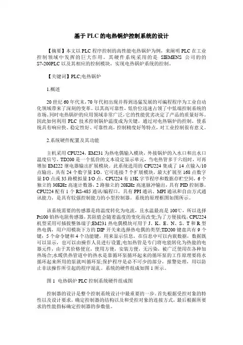
基于PLC的电热锅炉控制系统的设计【摘要】本文以PLC程序控制的高性能电热锅炉为例,来阐明PLC在工业控制领域中发挥的巨大作用。
其硬件系统采用的是SIEMENS公司的的S7-200PLC以及其相应的控制模块,实现电热锅炉系统的控制。
【关键词】PLC;电热锅炉1.概述20世纪60年代末,70年代初出现并得到迅猛发展的可编程程序为工业自动化领域带来了深刻的变革。
以其高可靠性,低价位迅速占领了中低端控制系统的市场。
同时电热锅炉的应用领域非常广泛,它的性能优劣决定了产品的质量好坏。
因此如何利用PLC技术控制锅炉温度成为关键。
通过对电热锅炉的控制,使系统具有响应快、稳定性好、可靠性高,控制精度好等特点,对工业控制很有意义。
2.系统硬件配置及其功能主机采用CPU224,EM231为热电偶输入模块,外接锅炉的入水口和出水口温度信号,TD200是一个低价的文本设定显示单元,当电热管多于六组时,可再增加EM222继电器输出扩展模块。
此系统选用的CPU224集成了14点输入/10点输出,共有24个数字量I/O。
它可连接7个扩展模块,最大扩展至168点数字量I/O点或35路模拟量I/O点。
CPU224有13K字节程序和数据存贮空间,6个独立的30KHz高速计数器,2路独立的20KHz高速脉冲输出,具有PID控制器。
CPU224配有1个RS-485通讯/编程口,具有PPI通讯、MPI通讯和自由方式通讯能力,是具有较强控制能力的小型控制器。
系统的原理框图如图所示。
该系统需要的传感器是将温度转化为电流,且水温最高是100℃,所以选择Pt100铂热电阻传感器,其阻值会随着温度的变化而改变;为了方便接线,CPU224机型采用可插拔整体端子;EM231热电偶模块可用于J、K、E、N、S、T和R型热电偶,用户用模块下方的DIP开关来选择热电偶的类型;TD200键盘共有9个键:5个命令键和4个功能键,用来显示信息,在信息中可以内嵌数据,数据既可以显示,也可以由操作人员进行设置;电加热管是专门将电能转化为热能的电器元件,由于其价格便宜,使用方便,安装方便,无污染,被广泛使用在各种加热场合;水暖供热管道中的热水是靠循环泵循环起来的循环泵的工作原理要将水循环起来所用的泵就叫循环泵;保护程序是必不可少的部分,报警处理,用以防止非法操作所引起的程序混乱。
文献综述电气工程及其自动化基于PLC 的燃油锅炉电气控制系统设计1.前言锅炉是一种能量转换设备,向锅炉输入的能量有燃料中的化学能、电能、高温烟气的热能等形式,而经过锅炉转换,向外输出具有一定热能的蒸汽、高温水或者有机热载体。
用油做燃料的锅炉叫燃油锅炉,燃油锅炉的使用是油的开发利用的一种重要方法。
燃油锅炉工作过程中涉及到的理论知识:(1)燃烧学(2)传热学(3)流体力学和工程热力学GX Developer 是三菱PLC 的编程软件。
适用于Q 、QnU 、QS 、QnA 、AnS 、AnA 、FX 等全系列可编程控制器。
支持梯形图、指令表、SFC 、 ST 及FB 、Label 语言程序设计,网络参数设定,可进行程序的线上更改、监控及调试,具有异地读写PLC 程序功能。
2.发展现状能源是人类社会和经济发展的基本条件之一,我国过去基本上依赖单一能源维持国民经济增长,能源的消费结构长期以来一直跟不上我国国民经济的发展和人民生活水平的提高。
我国能源生产和消费的主要特点是以煤炭为主。
一次能源生产的年平均增长率为2010年全国原煤产量约32亿吨,比2005年增长了1.5倍,‘十一五’期间原煤产量以6-7%的平均增速增长;2010年发电装机容量突破9.5亿千瓦,‘十一五’五年间扩建了4亿多千瓦,是过去50年装机容量的总和;同时,‘十一五’期间石油、天然气产量稳定在1.8-1.9亿吨之间,海外资源合作有突破性进展,国内炼油能力突破5亿吨。
”这种以煤为主的能源结构带来的问题是防止污染的费用日益增长;其次,对铁路运输业造成了压力。
据预测,到2020年我国能源需求量将至少增加t 标志煤。
因此,如何减少煤炭资源的消耗及不断开发可再生能源已经成810为我国解决能源矛盾的主要方向。
但是由于可再生能源,如太阳能、生物能、地热能等本身条件的限制,至少在21世纪前半叶,我国能源结构将不会做出很大改变。
同时,随着经济和科学技术的发展,特别是人类对生活质量和生存环境要求的日益增加,油作为优质洁净的燃料和原料,越来越引起人们的重视。
摘要本文设计了一套基于PLC和变频调速技术的供暖锅炉控制系统。
该控制系统由可编程控制器、变频器、鼓风机和水泵电机、传感器等构成。
系统通过变频器控制电动机的启动、运行和调速。
该设计以西门子S7-200系列可编程控制器为核心,一方面通过操作台与PLC 通讯,接收管理者的控制命令。
另一方面与各变频器进行通信,分别对鼓风机、循环泵和补水泵等进行启停控制和电机的转速设定,操作人员也随时可以通过操作台,了解现场每台锅炉的运行状况,对风机、水泵等电机进行启停控制。
控制系统的设计采用比例积分的PID控制。
关键词:锅炉控制,变频器,PLC ,PIDThe design of heating boiler auto control reformation system basedon PLC technologyAbstractIn this Paper,a heating boiler control system based on PLC and variable frequency Speed-regulating technology is designed. The control system is made up of PLC,transducers,electromotor units of Pumps and fans, sensors, etc. It can control electromotor starting,running and timing by means of transducers.The design is based on Siemens S7-200 series programmable controller as the core; on the one hand through the console it can communicate with the PLC, to receive control commands from managers. On the other hand it communicate with the variable frequency Speed-regulating, to fulfilled such as starting and stopping pump motor control and speed settings, the operator at console can find out at the scene of the operation of each boiler to fans, pumps and other motor control to start and stop. at any time.Key words:boiler control, variable frequency Speed-regulating, PLC technology目录1 绪论 (2)2 供暖锅炉改造设计思路 (2)2.1 供暖锅炉改造设计要求 (2)2.2 锅炉系统的结构 (3)2.3 整体方案选择 (3)3 变频调速在供暖锅炉控制中的应用 (4)3.1 变频调速基本原理 (4)3.2 变频调速在供暖锅炉系统中的应用 (5)4 锅炉控制系统总体设计 (5)4.1系统功能分析 (5)4.2 总体设计思路 (6)4.3 系统结构 (6)5 系统硬件设计 (7)5.1 可编程控制器PLC的选型 (7)5.2 PLC配置 (8)5.3 I/O接线 (9)5.4 变频器配置 (9)5.5 传感器与变送器 (11)5.5.1 压力变送器工作原理 (11)5.5.2 压力变送器选型 (11)5.5.3 温度传感器选型 (11)6 系统构成 (13)6.1 补水泵控制系统 (13)6.2 循环泵控制系统 (15)6.3 燃烧控制系统 (16)7 PID控制原理 (17)8 程序设计 (20)8.1 主程序设计 (16)8.2 子程序设计 (16)9 结束语 (26)致谢 (28)参考文献 (28)1 绪论锅炉是供热设备中最普遍的动力设备之一,它的功能是把燃料中的贮能,通过燃烧转化成热能,以蒸汽或热水的形式输向各种设备。
基于PLC的锅炉燃烧控制系统设计1 绪论1.1锅炉燃烧控制项目的背景改革开放以来,我国经济社会快速发展,生产力水平不断提高,在生产中,锅炉起着十分重要的作用,尤其是在火力发电中发挥重要作用的工业锅炉,是提供能源动力的主要设备之一。
锅炉产生的蒸汽可以作为蒸馏,干燥,反应,加热等各过程的热源,另外也可以作为动力源驱动动力设备。
工业过程中对于锅炉燃烧控制系统的要非常高的,要求锅炉燃烧控制系统必须满足控制精度高,响应速度快[1]。
作为一个非常复杂的设备,锅炉同时具有了数十个包括了扰动、测量、控制在的参数,参数之间有着复杂的关系,并且相互关联[2]。
而锅炉燃烧过程中的效率问题、安全问题一直是大众关注的重要方面。
1.2锅炉燃烧控制的发展历史对于锅炉燃烧的控制,已经经历了四个阶段[3~5](1)手动控制阶段因为20世纪60年代以前,电力电子技术和自动化技术还没有得到完全发展,技术尚不成熟,因此,这个时期工业人员的自动化意识不强,锅炉燃烧的控制方式一般多采用纯手动的方法。
这种控制方法,要求进行控制的操作工人依靠他们的经验决定送风量,引风量,给煤量的多少,然后利用手动的操作工具等操控锅炉,该方法控制的程度完全取决于操作工人的经验。
因此,要求操作工人必须具有非常丰富的经验,这样无疑大大提高了操作工人的劳动强度,由十人的主观意识,所以事故率非常大,同时,也不能保证锅炉高效稳定的运行。
(2)仪器继电器控制阶段随着科技的不断进步,自动化技术以及电力电子技术快速提高,国外以继电器为基础的自动化仪表工业锅炉控制系统也得到发展,并且广泛应用于实际生产过程。
在上个世纪60年代前期,我国锅炉的控制系统开始得到迅速发展;到了60年代的中后期,我国引进了国外全自动的燃油锅炉的控制系统;到了上个世纪的70年代末,我国逐渐自主研发了一些工业锅炉的自动化仪器,同时,在工业锅炉的控制系统方面也在逐步推广应用自动化技术。
在仪表继电器控制阶段,锅炉的热效率得到了提高,并且大幅度的降低了锅炉的事故率。
摘要在当今各种工业企业的动力设备中,锅炉仍然是一重要的组成部分。
随着现代化工业的飞速发展,对能源利用率的要求越来越高,作为将一次能源转化为二次能源的重要设备之一的锅炉,其控制和管理随之要求越来越高。
但在我们国家,除了一些大中型锅炉采用了先进的控制技术外,绝大多数中小企业所用的锅炉,如10T/h、20T/h锅炉,大部分还在采用仪表/继电器控制,甚至还是人工操作,已无法满足要求。
据此,本文针对一台10T/h 工业锅炉,提出了一套PLC的控制系统方案。
本文以一台10T/h锅炉的PLC控制系统为背景,理论与实践相结合,详细阐述了集PLC技术,变频器技术,通信技术于一体的先进控制技术在该锅炉控制系统中的应用。
在该系统中,应用了Siemens公司的S7-300系列PLC,根据锅炉的控制特点,分析系统的控制要求,实现给煤自动调节,送风自动调节,引风自动调节,水泵给水的自动调节,根据系统控制要求分析系统所需的PLC配置,以及备控量的I/O点数及I/O口分配,查阅S7-300使用手册在理论上分析确定PLC的组成及使用事项,并用其编程软件Step7设计锅炉控制的梯形图、STL语句及PLC通信网络,实现锅炉的水位三冲量控制、燃烧过程自动控制、蒸汽压力自动控制等功能;基于锅炉运行安全的考虑,该系统中锅炉由PLC控制,PLC、上位机组成一个MPI网,运用Siemens公司的MPI全局通讯技术及WinCC的软件设计,实现锅炉的上位机的冗余控制,关键词:锅炉变频器PLC PID WinCC Step7 MPI 全局通讯AbstractNowadays the boilers are still an important component among various power equipments in industrial enterprises. Along with the fast development of modem industry,high efficient energy utilization is pursued more and more. And the boiler are a kind of Primary equipments for converting raw energy into secondary energy,so their control and supervision is very important for promoting energy utilization efficiency. But in our country,only some big and medium-sized boilers have adopted.Advanced control technique. Most boilers being used by medium and small enterprises,such as 10T/h and 20T/h boilers,are controlled by mete/relays,or even manually. That can not meet demand. In this paper,a control system scheme of PLC+IPC is Proposed,which is aiming at a 10T/h industrial boilers.An advanced boiler control technique composed of PLC,inverter,and communication are detailly described with respect theory and application in this paper,which is based on two PLC control systems of 10T/h boilers in certain plant.The S7-300 series PLC of siemens company is adopted in the boiler control systems. The Step7 programming software is used to design the ladder chart,the STL language and the PLC correspondence network. Automatic control for the boilers has been realized,such as three impulse control for the water level,burning Process control,vapor pressure control. Moreover,an amicable man-machine interface,automatic storage of important boiler run data,and automatic print of reports in need is realized by using the configurations software WinCC of Siemens company. Each boiler in the system is controlled by one PLC respectively. PLC and IPC shaped into a MPI net. By using the MPI overall situation telecommunication technique and the WinCC software of Siemens company redundancy controls of the two IPC are designed for the safety. The automatic control of public facilities such as deoxidization equipment is also realized in the system.Key words: boiler,inverter,PLC,PID目录摘要 (I)ABSTRACT..................................................................................................................... I I 第一章绪论.. (1)1.1工业锅炉控制现状 (1)1.2工业锅炉控制的任务和特点 (1)1.2.1 工业锅炉控制的任务 (1)1.2.2工业锅炉给水自动控制 (2)1.2.3工业锅炉燃烧过程自动控制 (4)1.3PLC控制的优点 (7)1.4本文主要内容 (8)第二章锅炉控制系统的总体设计 (9)2.1系统控制要求 (9)2.2锅炉本体构造 (9)2.3系统设计思想 (10)2.3.1电机控制模式 (10)2.4各主要回路控制策略 (12)2.4.1锅炉生产工艺流程图及汽水系统 (12)2.4.2 主程序框图如下: (14)2.4.3 自动控制系统结构框图: (15)2.4.4 给水调节回路 (15)2.4.5汽包压力调节回路 (16)2.4.6炉膛负压调节回路 (17)2.4.7水位控制程序框图: (19)2.4.8燃烧控制回路程序框图: (20)第三章系统硬件组成 (21)3.1总体结构 (21)3.2系统硬件组成 (21)3.3主要器件选择 (21)3.4系统供电 (34)3.5系统接地 (35)3.6系统运行方式 (36)3.7PLC配置及I/O点分配: (36)3.7.1锅炉给水 (37)3.7.2锅筒 (38)3.7.3给煤 (38)3.7.4鼓风和引风 (40)3.7.5 炉膛 (42)3.7.6 出渣机: (42)3.7.7 蒸汽管路和省煤器: (42)第四章系统软件和设置 (44)4.1PLC软件设计 (44)4.1.1 Step7简介 (44)4.1.2 Step7的PlD功能块 (48)4.1.3 PLC程序总体结构 (53)4.1.4功能模块编程 (55)4.2系统通讯 (60)4.3本章小结 (60)结束语 (61)致谢 (62)参考文献 (63)附录1原理图 (65)附录2外文 (66)附录3翻译 (69)第一章绪论1.1 工业锅炉控制现状目前在我们国内,锅炉仍然是各种工业企业的动力设备中重要的组成部分。
东华理工大学长江学院文献综述论文题目:基于组态软件和PLC技术的锅炉燃烧的过程控制:学号:班级:年级:2011级专业:自动化系:机械与电子工程学院指导教师:完成时间:2015年6月1日文献综述—基于组态软件和PLC的锅炉燃烧的过程控制前言随着改革开放的进程,中国工业技术的快速发展,中国的工业技术已达到国际先进水平,工业领域中的控制系统更是中国工业发展的重中之重,随着生产技术水平的迅速提高与生产规模的持续扩大,对过程控制系统的要求越来越高,促使过程控制理论的研究不断发展。
现代控制系统技术在提高经济效益和劳动生产率,改善劳动条件,保护生态环境等方面发挥着越来越大的作用。
而锅炉燃烧的控制系统是在工业生产中占有绝对地位,因此锅炉燃烧空燃比控制的技术关系着工业技术的提高和生产效率的改进。
工业控制系统不断改进,可编程控制器(Programmable Logic Controller)简称PLC,是以微处理器为核心的工业自动控制通用装置。
它具有控制功能强,可靠性高,使用灵活方便,,易于扩展,通用性强等一系列优点,不仅可以取代继电器控制系统,还可以进行复杂的生产过程控制和应用于工厂自动化网络,被誉为现代工业生产自动化的三大支柱之一。
本次研究主要以锅炉为被控对象,以锅炉燃烧空燃比为主被控参数,以锅炉蒸汽压力为副被控参数,以PLC为控制器,构成锅炉燃烧的串级比值控制系统;采用PID算法,运用PLC梯形图编程语言进行编程,实现锅炉燃烧的自动控制。
是工业锅炉燃烧控制系统更加稳定,使控制系统更加准确。
是该系统更能在工业生产上更好的发挥准确的控制作用,从而提高工业生产的效率,推动工业生产的发展进程。
一基于PLC锅炉燃烧控制的发展背景和应用我们知道,锅炉燃烧的空燃比是工业生产中最常见和最重要的控制参数之一。
无论是科学实验,还是工业生产,任何物理和化学反应都与温度有十分密切的关系。
特别是食品,冶金,化工等领域,控制温度是整个工业流程的关键步骤。
专业英语项目作业指导教师班级姓名学号齐齐哈尔工程学院电气工程及其自动化专业2016年12月29日基于PLC的锅炉燃烧控制系统1 引言燃烧控制系统是电厂锅炉的主控系统,主要包括燃料控制系统、风量控制系统、炉膛压力控制系统。
目前大部分电厂的锅炉燃烧控制系统仍然采用PID控制。
燃烧控制系统由主蒸汽压力控制和燃烧率控制组成串级控制系统,其中燃烧率控制由燃料量控制、送风量控制、引风量控制构成,各个子控制系统分别通过不同的测量、控制手段来保证经济燃烧和安全燃烧.2 控制方案锅炉燃烧自动控制系统的基本任务是使燃料燃烧所提供的热量适应外界对锅炉输出的蒸汽负荷的要求,同时还要保证锅炉安全经济运行。
一台锅炉的燃料量、送风量和引风量三者的控制任务是不可分开的,可以用三个控制器控制这三个控制变量,但彼此之间应互相协调,才能可靠工作。
对给定出水温度的情况,则需要调节鼓风量与给煤量的比例,使锅炉运行在最佳燃烧状态.同时应使炉膛内存在一定的负压,以维持锅炉热效率、避免炉膛过热向外喷火,保证了人员的安全和环境卫生。
2。
1 控制系统总体框架设计燃烧过程自动控制系统的方案,与锅炉设备的类型、运行方式及控制要求有关,对不同的情况与要求,控制系统的设计方案不一样。
将单元机组燃烧过程被控对象看作是一个多变量系统,设计控制系统时,充分考虑工程实际问题,既保证符合运行人员的操作习惯,又要最大限度的实施燃烧优化控制。
控制系统的总体框架如图1所示。
图1单元机组燃烧过程控制原理图11徐亚飞,温箱温度PID与预测控测控制.2004,28(4):554-5572P为机组负荷热量信号。
控制系统包括:滑压运行主汽压力设定值计算模块(由热力系统实验获得数据,再拟合成可用DCS折线功能块实现的曲线)、负荷—送风量模糊计算模块、主蒸汽压力控制系统和送、引风控制系统等。
主蒸汽压力控制系统采用常规串级PID控制结构。
2.2 燃料量控制系统当外界对锅炉蒸汽负荷的要求变化时,必须相应的改变锅炉燃烧的燃料量.燃料量控制是锅炉控制中最基本也是最主要的一个系统。
摘要随着社会经济的飞速发展,城市建设规模的不断扩大,以及人们生活水平的不断提高,对城市生活供暖的用户数量和供暖质量提出了原来越高的要求。
结合现状,本论文供暖锅炉监控系统,设计了一套基于PLC和变频调速技术的供暖锅炉控制系统。
该控制系统以一台工业控制机作为上位机,以西门子S7-300可编程控制机为下位机,系统通过变频器控制电机的启动,运行和调速。
上位机监控采用WinCC设计,主要完成系统操作界面设计,实现系统启停控制,参数设定,报警联动,历史数据查询等功能。
下位机控制程序采用西门子公司的STEP7编程软件设计,主要完成模拟量信号的处理,温度和压力信号的PID控制等功能,并接受上位机的控制指令以完成风机启停控制,参数设定,循环泵的控制和其余电动机的控制。
本文设计的变频控制系统实现了锅炉燃烧过程的自动控制,系统运行稳定可靠。
采用锅炉的计算机控制和变频控制不仅可大大节约能源,促进环保,而且可以提高生产自动化水平,具有显著的经济效益和社会效益。
关键字:锅炉控制;变频调速;组态软件;PLCAbstractAlong with social economy’s swift development, the urban construction scale’s unceasing expansion , as well as the peple living standard’s unceasing enhancement , set more and more high request to the city life heating’s user quantity and the heating quality. The union present situation, the present paper heating boiler supervisory sysem, has designed a set based on PLC and the frequency conversion velocity modulation technology heating boiler control system.This control system takes the superior machine by one Industry cybertrons , west of family household S7-300 programmable controller for lower position machine ,system through frequency changer control motor’s start , movement and vclocity modulation .the superior machine monitoring software uses the three dimensional strength to control the WinCC design , mainly completes the system operation contract surface design ,realizes the system to open/stops functions and so on control ,parameter hypothesis ,warning linkage,historical data inquiry. The lower position machine control procedure uses Siemen’s STEP7 programming software design , mainly completes the simulation quantity signal processing , temperature and pressure signal functions and so on PID control , and receives the superior machine control command to complete the air blower to open/stops the control , the parameter hypothesis, the circulating pump control and other electric motor’s control.This article designs the frequency conversion processs automatic control, the systems operation is stable, is reliable. Uses boiler’s computer control and the frequency converseon control noe only may save the energy greatly, the promotion environmental protection moreover may raise the production automation level, has the remarkable economic efficiency and the social efficiency.Key Words:Boiler control;Frequency conversion velocity modulation ;Configuration Software;PLC目录摘要 0Abstract (1)第1章概述 (4)1.1 项目背景及课题的研究意义 (4)1.2 供暖锅炉控制的国内外研究现状 (5)1.3锅炉控制系统的发展趋势 (6)1.4本文所做工作 (7)第2章系统方案设计 (9)2.1锅炉控制研究简介 (9)2.2 总体设计思路 (9)2.3方案比较 (10)2.3.1方案1 (10)2.3.2 方案2 (10)2.4方案论证与方案确定 (11)第3章硬件设计 (12)3.1 用户系统框图 (12)3.2 锅炉系统的理论分析 (13)3.2.1变频调速基本原理 (13)3.2.2变频调速在供暖锅炉中的应用 (13)3.2.3变频调速节能分析 (14)3.3燃烧过程控制 (19)3.4锅炉控制系统设计 (20)3.5控制系统构成介绍 (21)第4章软件设计 (25)4.1 S7-300系列PLC简介 (26)4.2 PLC编程语言简介 (28)4.2.1 PLC编程语言的国际标准 (28)4.2.2复合数据类型与参数类型 (29)4.2.3系统存储器 (29)4.2.4 S7-300 CPU中的寄存器 (30)4.3 STEP7 的原理 (31)4.3.1 STEP7概述 (31)4.3.2 硬件组态与参数设置 (32)4.3.3 符号表 (36)4.3.4 逻辑块 (37)4.3程序设计 (38)4.4通信系统 (41)4.5人机界面 (43)4.5.1监控软件WinCC介绍 (43)4.5.2监控系统设计 (45)4.5.3锅炉监控界面设计 (49)第5章结论 (53)5.1 成果的创造性和先进性 (53)5.2作用意义(经济效益和社会意义) (53)5.3 推广应用范围和前景 (53)5.4 需要进一步改进之处 (54)参考文献 (55)外文资料翻译 (56)外文翻译原文 (56)外文翻译译文 (68)致谢 (75)附录 (76)附录1 程序清单 (76)附录2 I/O点数分配表 (96)附录3 物理参数比较表 (97)第1章概述1.1 项目背景及课题的研究意义工业锅炉是工业生产和集中供热过程中重要的动力设备。
专业英语项目作业指导教师班级姓名学号齐齐哈尔工程学院电气工程及其自动化专业2016年12月29日基于PLC的锅炉燃烧控制系统1 引言燃烧控制系统是电厂锅炉的主控系统,主要包括燃料控制系统、风量控制系统、炉膛压力控制系统。
目前大部分电厂的锅炉燃烧控制系统仍然采用PID控制。
燃烧控制系统由主蒸汽压力控制和燃烧率控制组成串级控制系统,其中燃烧率控制由燃料量控制、送风量控制、引风量控制构成,各个子控制系统分别通过不同的测量、控制手段来保证经济燃烧和安全燃烧。
2 控制方案锅炉燃烧自动控制系统的基本任务是使燃料燃烧所提供的热量适应外界对锅炉输出的蒸汽负荷的要求,同时还要保证锅炉安全经济运行。
一台锅炉的燃料量、送风量和引风量三者的控制任务是不可分开的,可以用三个控制器控制这三个控制变量,但彼此之间应互相协调,才能可靠工作。
对给定出水温度的情况,则需要调节鼓风量与给煤量的比例,使锅炉运行在最佳燃烧状态。
同时应使炉膛内存在一定的负压,以维持锅炉热效率、避免炉膛过热向外喷火,保证了人员的安全和环境卫生。
2.1 控制系统总体框架设计燃烧过程自动控制系统的方案,与锅炉设备的类型、运行方式及控制要求有关,对不同的情况与要求,控制系统的设计方案不一样。
将单元机组燃烧过程被控对象看作是一个多变量系统,设计控制系统时,充分考虑工程实际问题,既保证符合运行人员的操作习惯,又要最大限度的实施燃烧优化控制。
控制系统的总体框架如图1所示。
图1单元机组燃烧过程控制原理图11徐亚飞,温箱温度PID与预测控测控制.2004,28(4):554-5572P为机组负荷热量信号。
控制系统包括:滑压运行主汽压力设定值计算模块(由热力系统实验获得数据,再拟合成可用DCS折线功能块实现的曲线)、负荷—送风量模糊计算模块、主蒸汽压力控制系统和送、引风控制系统等。
主蒸汽压力控制系统采用常规串级PID控制结构。
2.2 燃料量控制系统当外界对锅炉蒸汽负荷的要求变化时,必须相应的改变锅炉燃烧的燃料量。
燃煤锅炉PLC控制系统设计摘要:本文设计了一种基于PLC的燃煤锅炉控制系统。
该系统采用了微型PLC来进行燃煤锅炉控制,能够实现数字化、自动化、智能化的控制方式,提高了燃煤锅炉的运行效率和安全性。
该系统还具有故障自动检测和报警处理功能,可以及时发现并排除系统中的故障,确保了系统的可靠性。
关键词:PLC,燃煤锅炉,控制系统,数字化,自动化,智能化正文:燃煤锅炉是工业生产中常见的一种设备,对于实现工业生产的高效、低成本运行具有重要作用。
传统的燃煤锅炉控制方式主要是采用模拟控制方式,但由于模拟控制存在误差大、灵敏度不高、抗干扰能力差等问题,近年来越来越多的燃煤锅炉采用数字化控制方式进行控制。
数字化控制方式采用先进的PLC控制器来控制燃煤锅炉,能够实现数字化、自动化、智能化的控制方式。
本文设计的基于PLC的燃煤锅炉控制系统主要由微型PLC、人机界面、执行器、传感器等组成。
系统的控制算法采用PID 控制方法,能够实现对燃煤锅炉的加热温度、空燃比等参数进行精确控制,提高了燃煤锅炉的运行效率和安全性。
同时,该系统还具有故障自动检测和报警处理功能,当系统出现异常情况时能够及时发现并排除故障,确保了系统的可靠性。
系统的人机界面采用触摸屏和键盘进行交互,能够实时显示燃煤锅炉的运行状态,并支持远程监控和控制功能。
为了验证该系统的性能,本文进行了模拟实验和现场应用测试。
模拟实验结果表明,系统的控制精度高、稳定性好;现场应用测试结果表明,系统可靠性高、使用方便,运行效率明显提高。
总之,本文设计的基于PLC的燃煤锅炉控制系统具有数字化、自动化、智能化的控制方式,能够确保燃煤锅炉的高效、安全运行。
同时,该系统具有故障自动检测和报警处理功能,能够及时发现并排除故障。
本文的设计思路和实验结果可以为相关领域的工程技术人员和研究人员提供借鉴和参考。
本文设计的燃煤锅炉PLC控制系统具有以下几个特点:1.数字化控制:传统的燃煤锅炉控制方式主要是采用模拟控制方式,但由于模拟控制存在误差大、灵敏度不高、抗干扰能力差等问题,近年来越来越多的燃煤锅炉采用数字化控制方式进行控制。
Boiler level control system based onControlLogix5550 PLCAbstract-This paper is a research design based on EFPT process control device. In the design, actual industry field has been simulated and corresponding modeling has been carried on for the boiler level system. Then the appropriate PID parameter has been sorted out and ControlLogia5550PLC has been used to control the entire boiler level system.At last, a corresponding control interface has been established and the boiler level has been under a safe and accurate controlK eywords:EFPT,PID,Modeling,Boiler level;1 IntroductionThe task of the industrial boiler level control is to maintain a dynamic balance by controlling the water flow and evaporation, so that the drum level can be maintained in the technological level, which is a necessity for ensuring safe operation and also one of the main indicators of the boiler's normal operation. Water level which is too high will affect the effect of the steam-water separation, but too low it is will break ring cycle or even cause boiler explosion. To ensure a safe and efficient production, the boiler level must be strictly controlled in maintaining constant or changing only according to a certain rule.Using Logix5550 PLC with analogy I/O modules, launched by Rockwell Automation Company as controllers, and EFPT process control experimental device as control object, this system have brought the boiler water level under an accurate control in a mini boiler system with sensors and actuators that used in industrial production.Fig. 1 Boiler level setting value adjustment system2 System OverviewThis system is composed of an EFPT process control device, an inverter, a Logix5550 PLC and a computer. EFPT process control device is a simulated heating and water supply and drainage system for a micro-small boiler. It realizes process control in a mini boiler system with sensors and actuators used in industrial production. The actuator includes not only measuring appliance, but also AC inverter, heating controller, heater and so on. The system simulates industry scene through a mini-boiler heating, water supply and drainage system, which is reliable and visual.In the design, boiler Level was selected as the controlled variable. The controlled object is composed of the water trough, the force pump, the boiler and the pipe-line valve. Micro Master 6SE9214-ODA40 inverter is taken as the actuator and the boiler level is controlled by Logix5550. Configuration software RSView32 and touch screen PanelView1000 are combined to realize the real-time monitoring. In the design, a simple design of single-loop boiler liquid level value adjustment is selected for the study. The composition of the system is shown in Fig. 1.In the design, the inverter as an actuator directly receives PLC analogy I/O port output, and converters into frequency of inverter so as to drive the 3-phase motorin the lift pump, change the inlet, and adjust the boiler level to the dynamic balance at last. And the configuration software is used to design monitoring picture to realize the computer and the touch screen to the boiler level long-distance and the scene monitoring.3 Establishing Mathematics model for the charged objectOne of the main tasks of establishing control system mathematical model is to determine the mathematical model of the controlled object. Generally, there are two kinds of basic methods for establishing process control mathematical model: mechanism analysis and experimental method. However, for controlled object whose structure and internal process is very complex, it is very difficult to determine the object just by its own internal physical process and to solve out the differential equations systematically. Besides, considering the nonlinear factor, mechanism analysis used some approximation and hypothesis for mathematical deduction. Although these approximation and assumptions have practical basis, but not fully reflect actual situation, and even cause incalculable effects.Therefore, in this design, the experimental method is chosen to establish a mathematical model for controlled object. This kind of modeling is based on the input and output in the actual production process, that is to say, establishing mathematical model for the controlled object through process identification and parameter estimation. In this design, step response curve method is used to identify mathematical models of the process. A 20Hz step disturbance input signal is applied to the charged object, and the response curve of the output that changes with time can be mapped. After the analysis, the transfer function of the controlled object can be defined. In the process of experiment, the object was conducted several tests. Using RSLogix5000 trend monitoring function curve, more than 10 charged object step response curve have been recorded. To all the parameters for average, steady time: ts≈821.525s, steady value: h(∞)=58.5, peak time: tp=394.4s overshoot: a%}29%. According to the theoretical analysis, the controlled object is the most likely second-order object.However, the difference is very apparent between the ideal second-ordercontrolled object step response curve and the actual curves. So the ideal curve can't response to its actual characteristics. It is inferred that the controlled object may be the second-order controlled object that includes zero. The try and error method and MATLAB simulation tools are used to get a curve whose parameters are close to the average dynamic parameters of the controlled object's response curve. It is shown in Fig. 2.Some adjustments can be made according to the following rules:1) When the zero is closer to the imaginary axis, settling time will be longer and the overshoot will be bigger and peak time will be smaller. With the zero closing to the imaginary axis, the effect is more obvious.2) The effect which the closed loop dominant apices have on dynamic performance is increasing the peak time, reducing the overshoot and adjusting time. Nonparametric model is used to describe the controlled object. In other words, step response curve which approximately describe the controlled object is used because of the controlled object's complexity and uncertainty.4 The installation of controller parameter4.1 The selection of control algorithmAfter establishing the approximate mathematical model of the controlled object, a complete feedback control system can be formed to improve the performance of the open-loop control system. PID is an ideal control law in that integral is introduced basing on the proportion, which can eliminate the residual error, plus the derivative action, which can also improve the stability of the system. According to the characteristics of the controlled object and laboratory conditions, a single-loop feedback control loop for the controlled object is established, and PID algorithm is used to realize boiler level control. The schematic diagram of level control is shown in Fig. 3.Open the outlet valve to a certain degree, and make the hydraulic dischargeinvariable. Comparing the process variables of the water level in feedback with the given volume, the deviation can be obtained. PID instruction does PID operation on the deviation, and the results is a control variable, so the frequency of the inverter can be changed to control the rotate speed of the pump. If the liquid level is on the high side, the results make the control variable smaller, andreduce the rate of inflow, make liquid level lower; if the level is on the low side, the results make the control variable larger, and increase the rate of inflow, make liquid level higher.4.2 The Parameter Tuning of PIDBecause the transfer function of the controlled object includes a zero second-order link, the computation work load is quite big regardless of using the root-locus method or the frequency characteristic law among theory methods when tuning PID parameter. And the process mathematical model can only reflect dynamic parameter approximately, so the reliability of the parameter value which is obtained by the theoretical calculation is not very accurate and it will be adjusted constantly in the scene. Therefore, engineering parameter tuning is chosen to seek the PID parameter in the design. The common method of engineering tuning are dynamic characteristic parameters, the stable boundary law, the decay curve law and field experience setting method, etc. In the process of PID parameters, the 4:1 decay curve law isadopted. The steps are:1) In the closed system, regulator's integral time is set the largest (Ti≈∞) and differential time Td is set zero (Td=0). The proportion is taken the great value to perform the given value perturbation experiment repeatedly, and the proportion is reduced gradually until the record curve presents up to 4:1 weaken. Then the proportion is called 4:1 weaken proportion s sand the distances between two neighboring wave ridge's are called 4:1 damped cycle Ts. In the experiment, the level quantitative test is set for the 200mm, and then the system response curve is obtained and reorganized 4:1 decay curve (thick red line is shown in Fig. 4'Thus measuring: δs≈8,Ts≈2.2;2) According to the following formula, each parameter of the regulators isδ=0.8, δs≈6.4;Ti=0.3, Ts≈6.6;Td=0.1, Ts≈2.23) According to these results, regulator parameters are set. Then the dynamic process of system is observed and the parameters are made adjustment to determine the optimum parameters.5 Monitoring DesignRSView32 software and PanelBuilder32 software of Rockwell Automation Company are respectively used to design monitor screen to complete such function as animating display, parameter setting, report output, the current curve display and history curve display and so on. And make the computer and touch screen achieve the remote and on-site control to the boiler liquid level. Thepicture screen of system monitor is shown in Fig.5The main work of realizing configuration is to establish level control objects and make animating display scenes. Controlled objects include inletting water flow, exporting water flow and the numerical object of the boiler level. When animation connection is established, the basic graphic elements and animation component library are called in the user window to construct configuration diagram. Graphic objects and data objects defined by the state are set in the state of the corresponding attribute and animation connection is defined. Having finished the design ofthe developing system, you can switch to run mode to carry on the real-time monitoring to the control system and test configuration.6 ConclusionsThis paper has introduced the composition and running of EFPT process control system based on ControlLogix5550 PLC control, the mathematical model establishing of controlled object and the parameter tuning of PID. The use ofconfiguration software extends the communication function. Through experimental testing, the control curve's overshoot is small and the transition time is short, so the control effect is quite ideal. This device being reliable and intuitive is suitable for scientific research and teaching, and has important application value in the actual industrial production.。
采用PLC – SCADA进行锅炉运行控制果卫.尚卡尔摘要本文概述了涉及各阶段由手动操作锅炉转换实现成一个完全自动化的锅炉。
多年来,高品质、更高的效率和自动化的设备已在这个日益全球化的世界需求越来越多。
本课题的初始阶段集中在所需的温度下,将输入传递到锅炉,以恒定地保持锅炉中的一个特定的温度。
空气预热器和省煤器有助于这一进程。
纸张主要集中在锅炉厂的各个阶段的液位,压力和流量控制。
因此,在锅炉中的温度不断监测和由电厂的要求带来了一个恒定的温度。
进一步增强了不断监测使用SCADA画面通过通信电缆连接到PLC的自动化。
通过设置各种变量的变量值在SCADA的整个过程中根据需要控制。
在自动化电厂,控制锅炉的变频驱动器(VFD),把在上面的锅炉动作所需的过程进行下去。
因此,在整个周期进行记录下来,并记下不同阶段详细过程。
本文已被证明是非常有效的,实际上作为自动化的需要与日俱增。
索引条款自动化 PLC - 的SCADA 锅炉。
1 引言多年来,高品质、更高的效率和自动化设备的需求已在工业界发电厂日益增加。
发电厂需要在频繁的时间间隔的连续监测和检查。
有测量和涉及的各个阶段与人类的工人,还缺少一些功能的微控制器的错误的可能性。
因此,本文以真诚的试图解释的优势企业将面临到他们实现自动化。
任何电厂锅炉控制,都是最重要的部分及其自动化是精确本文的努力。
K. Gowri 尚卡尔系电子和本地治里大学通信工程学院,工程技术学院拉吉夫·甘地,印度(电子邮件:gowri200@)为了某电厂自动化,减少人为干预,有必要制定一个SCADA(监控和数据采集)系统,监控厂房及有助于减少人为造成的错误。
虽然SCADA用来监视系统,PLC(可编程逻辑控制器)也用于内部存储的指令执行功能,如逻辑,时序控制,定时,计数和算术运算控制通过数字或模拟式输入/输出模块各种类型的机器进程。
系统用于监测和控制机器或设备的行业,如电信,水和废物控制,能源,石油和天然气提炼和运输。
Boiler level control system based onControlLogix5550 PLCAbstract-This paper is a research design based on EFPT process control device. In the design, actual industry field has been simulated and corresponding modeling has been carried on for the boiler level system. Then the appropriate PID parameter has been sorted out and ControlLogia5550PLC has been used to control the entire boiler level system.At last, a corresponding control interface has been established and the boiler level has been under a safe and accurate controlK eywords:EFPT,PID,Modeling,Boiler level;1 IntroductionThe task of the industrial boiler level control is to maintain a dynamic balance by controlling the water flow and evaporation, so that the drum level can be maintained in the technological level, which is a necessity for ensuring safe operation and also one of the main indicators of the boiler's normal operation. Water level which is too high will affect the effect of the steam-water separation, but too low it is will break ring cycle or even cause boiler explosion. To ensure a safe and efficient production, the boiler level must be strictly controlled in maintaining constant or changing only according to a certain rule.Using Logix5550 PLC with analogy I/O modules, launched by Rockwell Automation Company as controllers, and EFPT process control experimental device as control object, this system have brought the boiler water level under an accurate control in a mini boiler system with sensors and actuators that used in industrial production.Fig. 1 Boiler level setting value adjustment system2 System OverviewThis system is composed of an EFPT process control device, an inverter, a Logix5550 PLC and a computer. EFPT process control device is a simulated heating and water supply and drainage system for a micro-small boiler. It realizes process control in a mini boiler system with sensors and actuators used in industrial production. The actuator includes not only measuring appliance, but also AC inverter, heating controller, heater and so on. The system simulates industry scene through a mini-boiler heating, water supply and drainage system, which is reliable and visual.In the design, boiler Level was selected as the controlled variable. The controlled object is composed of the water trough, the force pump, the boiler and the pipe-line valve. Micro Master 6SE9214-ODA40 inverter is taken as the actuator and the boiler level is controlled by Logix5550. Configuration software RSView32 and touch screen PanelView1000 are combined to realize the real-time monitoring. In the design, a simple design of single-loop boiler liquid level value adjustment is selected for the study. The composition of the system is shown in Fig. 1.In the design, the inverter as an actuator directly receives PLC analogy I/O port output, and converters into frequency of inverter so as to drive the 3-phase motorin the lift pump, change the inlet, and adjust the boiler level to the dynamic balance at last. And the configuration software is used to design monitoring picture to realize the computer and the touch screen to the boiler level long-distance and the scene monitoring.3 Establishing Mathematics model for the charged objectOne of the main tasks of establishing control system mathematical model is to determine the mathematical model of the controlled object. Generally, there are two kinds of basic methods for establishing process control mathematical model: mechanism analysis and experimental method. However, for controlled object whose structure and internal process is very complex, it is very difficult to determine the object just by its own internal physical process and to solve out the differential equations systematically. Besides, considering the nonlinear factor, mechanism analysis used some approximation and hypothesis for mathematical deduction. Although these approximation and assumptions have practical basis, but not fully reflect actual situation, and even cause incalculable effects.Therefore, in this design, the experimental method is chosen to establish a mathematical model for controlled object. This kind of modeling is based on the input and output in the actual production process, that is to say, establishing mathematical model for the controlled object through process identification and parameter estimation. In this design, step response curve method is used to identify mathematical models of the process. A 20Hz step disturbance input signal is applied to the charged object, and the response curve of the output that changes with time can be mapped. After the analysis, the transfer function of the controlled object can be defined. In the process of experiment, the object was conducted several tests. Using RSLogix5000 trend monitoring function curve, more than 10 charged object step response curve have been recorded. To all the parameters for average, steady time: ts≈821.525s, steady value: h(∞)=58.5, peak time: tp=394.4s overshoot: a%}29%. According to the theoretical analysis, the controlled object is the most likely second-order object.However, the difference is very apparent between the ideal second-ordercontrolled object step response curve and the actual curves. So the ideal curve can't response to its actual characteristics. It is inferred that the controlled object may be the second-order controlled object that includes zero. The try and error method and MATLAB simulation tools are used to get a curve whose parameters are close to the average dynamic parameters of the controlled object's response curve. It is shown in Fig. 2.Some adjustments can be made according to the following rules:1) When the zero is closer to the imaginary axis, settling time will be longer and the overshoot will be bigger and peak time will be smaller. With the zero closing to the imaginary axis, the effect is more obvious.2) The effect which the closed loop dominant apices have on dynamic performance is increasing the peak time, reducing the overshoot and adjusting time. Nonparametric model is used to describe the controlled object. In other words, step response curve which approximately describe the controlled object is used because of the controlled object's complexity and uncertainty.4 The installation of controller parameter4.1 The selection of control algorithmAfter establishing the approximate mathematical model of the controlled object, a complete feedback control system can be formed to improve the performance of the open-loop control system. PID is an ideal control law in that integral is introduced basing on the proportion, which can eliminate the residual error, plus the derivative action, which can also improve the stability of the system. According to the characteristics of the controlled object and laboratory conditions, a single-loop feedback control loop for the controlled object is established, and PID algorithm is used to realize boiler level control. The schematic diagram of level control is shown in Fig. 3.Open the outlet valve to a certain degree, and make the hydraulic dischargeinvariable. Comparing the process variables of the water level in feedback with the given volume, the deviation can be obtained. PID instruction does PID operation on the deviation, and the results is a control variable, so the frequency of the inverter can be changed to control the rotate speed of the pump. If the liquid level is on the high side, the results make the control variable smaller, andreduce the rate of inflow, make liquid level lower; if the level is on the low side, the results make the control variable larger, and increase the rate of inflow, make liquid level higher.4.2 The Parameter Tuning of PIDBecause the transfer function of the controlled object includes a zero second-order link, the computation work load is quite big regardless of using the root-locus method or the frequency characteristic law among theory methods when tuning PID parameter. And the process mathematical model can only reflect dynamic parameter approximately, so the reliability of the parameter value which is obtained by the theoretical calculation is not very accurate and it will be adjusted constantly in the scene. Therefore, engineering parameter tuning is chosen to seek the PID parameter in the design. The common method of engineering tuning are dynamic characteristic parameters, the stable boundary law, the decay curve law and field experience setting method, etc. In the process of PID parameters, the 4:1 decay curve law isadopted. The steps are:1) In the closed system, regulator's integral time is set the largest (Ti≈∞) and differential time Td is set zero (Td=0). The proportion is taken the great value to perform the given value perturbation experiment repeatedly, and the proportion is reduced gradually until the record curve presents up to 4:1 weaken. Then the proportion is called 4:1 weaken proportion s sand the distances between two neighboring wave ridge's are called 4:1 damped cycle Ts. In the experiment, the level quantitative test is set for the 200mm, and then the system response curve is obtained and reorganized 4:1 decay curve (thick red line is shown in Fig. 4'Thus measuring: δs≈8,Ts≈2.2;2) According to the following formula, each parameter of the regulators isδ=0.8, δs≈6.4;Ti=0.3, Ts≈6.6;Td=0.1, Ts≈2.23) According to these results, regulator parameters are set. Then the dynamic process of system is observed and the parameters are made adjustment to determine the optimum parameters.5 Monitoring DesignRSView32 software and PanelBuilder32 software of Rockwell Automation Company are respectively used to design monitor screen to complete such function as animating display, parameter setting, report output, the current curve display and history curve display and so on. And make the computer and touch screen achieve the remote and on-site control to the boiler liquid level. Thepicture screen of system monitor is shown in Fig.5The main work of realizing configuration is to establish level control objects and make animating display scenes. Controlled objects include inletting water flow, exporting water flow and the numerical object of the boiler level. When animation connection is established, the basic graphic elements and animation component library are called in the user window to construct configuration diagram. Graphic objects and data objects defined by the state are set in the state of the corresponding attribute and animation connection is defined. Having finished the design ofthe developing system, you can switch to run mode to carry on the real-time monitoring to the control system and test configuration.6 ConclusionsThis paper has introduced the composition and running of EFPT process control system based on ControlLogix5550 PLC control, the mathematical model establishing of controlled object and the parameter tuning of PID. The use ofconfiguration software extends the communication function. Through experimental testing, the control curve's overshoot is small and the transition time is short, so the control effect is quite ideal. This device being reliable and intuitive is suitable for scientific research and teaching, and has important application value in the actual industrial production.。