TLE202x-Q1, TLE202xA-Q1EXCALIBUR HIGH-SPEED LOW-POWER PRECISION High Unity-Gain Bandwidth ...2 MHz Typ D High Slew Rate ...0.45 V/μs Min D
Supply-Current Change Over Full Temp Range ...10 μA Typ at V CC ±=±15 V
Low Offset Voltage ...100 μV Max D Offset Voltage Drift With Time 0.005 μV/mo Typ D Low Input Bias Current ...50 nA Max D Low Noise Voltage ...19 nV/√Hz Typ description
The TLE202x and TLE202xA devices are precision, high-speed, low-power operational amplifiers using a new Texas I nstruments Excalibur process. These devices combine the best features of the OP21 with highly improved slew rate and unity-gain bandwidth.
The complementary bipolar Excalibur process utilizes isolated vertical pnp transistors that yield dramatic improvement in unity-gain bandwidth and slew rate over similar devices.
The addition of a bias circuit in conjunction with this process results in extremely stable parameters with both time and temperature. This means that a precision device remains a precision device even with changes in temperature and over years of use.
This combination of excellent dc performance with a common-mode input voltage range that includes the negative rail makes these devices the ideal choice for low-level signal conditioning applications in either single-supply or split-supply configurations. In addition, these devices offer phase-reversal protection circuitry that eliminates an unexpected change in output states when one of the inputs goes below the negative supply rail.
A variety of available options includes small-outline versions for high-density systems applications.
The Q-suffix devices are characterized for operation over the full automotive temperature range of ?40°C to 125°C.
PRODUCTION DATA information is current as of publication d ate.Please be aware that an important notice concerning availability, standard warranty, and use in critical applications of Texas Instruments semiconductor products and disclaimers thereto appears at the end of this data sheet.
TLE202x-Q1, TLE202xA-Q1EXCALIBUR HIGH-SPEED LOW-POWER PRECISION OPERATIONAL AMPLIFIERS
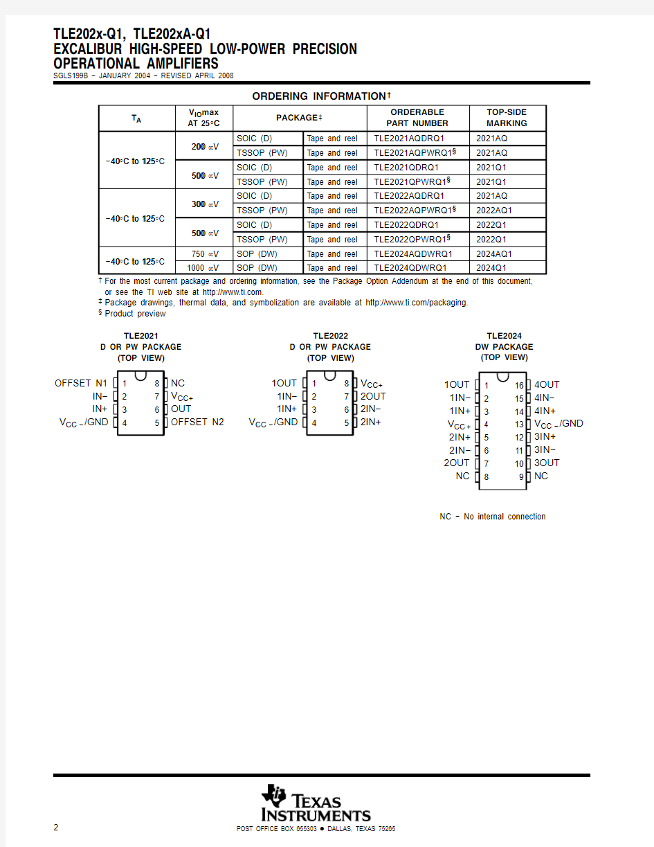
SGLS199B ? JANUARY 2004 ? REVISED APRIL 2008ORDERING INFORMATION ?
T A V IO max
AT 25°C
PACKAGE ?ORDERABLE PART NUMBER TOP-SIDE MARKING 200SOIC (D)Tape and reel TLE2021AQDRQ12021AQ 40°C to 125°C
200
μV TSSOP (PW)Tape and reel TLE2021AQPWRQ1§2021AQ ?40C to 125500SOIC (D)Tape and reel TLE2021QDRQ12021Q1500
μV TSSOP (PW)Tape and reel TLE2021QPWRQ1§2021Q1300SOIC (D)Tape and reel TLE2022AQDRQ12021AQ 40°C to 125°C
300
μV TSSOP (PW)Tape and reel TLE2022AQPWRQ1§2022AQ1?40C to 125500SOIC (D)Tape and reel TLE2022QDRQ12022Q1500
μV TSSOP (PW)Tape and reel TLE2022QPWRQ1§2022Q140°C to 125°C
750 μV SOP (DW)Tape and reel TLE2024AQDWRQ12024AQ1?40C to 1251000 μV SOP (DW)Tape and reel TLE2024QDWRQ12024Q1?For the most current package and ordering information, see the Package Option Addendum at the end of this document,
or see the TI web site at https://www.doczj.com/doc/6d9623569.html,.
?Package drawings, thermal data, and symbolization are available at https://www.doczj.com/doc/6d9623569.html,/packaging.
§Product preview
12348765OFFSET N1
IN?
IN+
V CC ?/GND NC V CC+OUT OFFSET N2TLE2021
D OR PW PACKAGE
(TOP VIEW)123487651OUT 1IN?1IN+V CC ?/GND V CC+2OUT 2IN?2IN+TLE2022D OR PW PACKAGE (TOP VIEW)1234 56781615141312111091OUT 1IN?1IN+V CC +
2IN+
2IN?
2OUT
NC 4OUT 4IN?4IN+V CC ?/GND 3IN+3IN?3OUT NC
TLE2024DW PACKAGE (TOP VIEW)
NC ? No internal connection
TLE202x-Q1, TLE202xA-Q1EXCALIBUR HIGH-SPEED LOW-POWER PRECISION OPERATIONAL AMPLIFIERS SGLS199B ? JANUARY 2004 ? REVISED APRIL 2008equivalent schematic (each amplifier)
IN ?Q23Q25Q1
Q2
Q3Q4Q5
Q6Q7Q8Q9Q10Q11Q12Q13Q14Q15Q16Q17
Q18Q19Q20
Q21Q22Q24Q26Q27
Q28Q29
Q30Q31Q32Q33Q34Q35Q36Q37Q38Q39Q40D1D2D3D4IN +OUT OFFSET N1(see Note A)
V CC+
V CC ?/GND
C1
R1
R2R3R4R5C2
R6
R7C4C3OFFSET N2(see Note A)ACTUAL DEVICE COMPONENT COUNT
COMPONENT
TLE2021TLE2022TLE2024Transistors
4080160Resistors
71428Diodes
4816Capacitors 4816
TLE202x-Q1, TLE202xA-Q1
EXCALIBUR HIGH-SPEED LOW-POWER PRECISION OPERATIONAL AMPLIFIERS
SGLS199B ? JANUARY 2004 ? REVISED APRIL 2008
absolute maximum ratings over operating free-air temperature range (unless otherwise noted)?Supply voltage, V CC+ (see Note 1) 20 V
. . . . . . . . . . . . . . . . . . . . . . . . . . . . . . . . . . . . . . . . . . . . . . . . . . . . . . . . . . .
Supply voltage, V CC? (see Note 1) ?20 V
. . . . . . . . . . . . . . . . . . . . . . . . . . . . . . . . . . . . . . . . . . . . . . . . . . . . . . . . . .
Differential input voltage, V ID (see Note 2) ±0.6 V
. . . . . . . . . . . . . . . . . . . . . . . . . . . . . . . . . . . . . . . . . . . . . . . . . . .
Input voltage range, V I (any input, see Note 1) ±V CC
. . . . . . . . . . . . . . . . . . . . . . . . . . . . . . . . . . . . . . . . . . . . . . . .
Input current, I I (each input) ±1 mA
. . . . . . . . . . . . . . . . . . . . . . . . . . . . . . . . . . . . . . . . . . . . . . . . . . . . . . . . . . . . . . .
Output current, I O (each output):TLE2021 ±20 mA
. . . . . . . . . . . . . . . . . . . . . . . . . . . . . . . . . . . . . . . . . . . . . . . . .
TLE2022 ±30 mA
. . . . . . . . . . . . . . . . . . . . . . . . . . . . . . . . . . . . . . . . . . . . . . . . .
TLE2024 ±40 mA
. . . . . . . . . . . . . . . . . . . . . . . . . . . . . . . . . . . . . . . . . . . . . . . . .
Total current into V CC+80 mA
. . . . . . . . . . . . . . . . . . . . . . . . . . . . . . . . . . . . . . . . . . . . . . . . . . . . . . . . . . . . . . . . . . .
Total current out of V CC?80 mA
. . . . . . . . . . . . . . . . . . . . . . . . . . . . . . . . . . . . . . . . . . . . . . . . . . . . . . . . . . . . . . . . .
Duration of short-circuit current at (or below) 25°C (see Note 3) unlimited
. . . . . . . . . . . . . . . . . . . . . . . . . . . . . .
Operating free-air temperature range, T A: Q suffix ?40°C to 125°C
. . . . . . . . . . . . . . . . . . . . . . . . . . . . . . . . . . .
Operating virtual junction temperature, T J150°C
. . . . . . . . . . . . . . . . . . . . . . . . . . . . . . . . . . . . . . . . . . . . . . . . . . .
Package thermal impedance, RθJA (see Notes 4 and 5):D (8 pin) 97°C/W
. . . . . . . . . . . . . . . . . . . . . . . . . . . . .
DW (16 pin) 57°C/W
. . . . . . . . . . . . . . . . . . . . . . . . . .
PW (8 pin) 149°C/W
. . . . . . . . . . . . . . . . . . . . . . . . . .
PW (14 pin) 113°C/W
. . . . . . . . . . . . . . . . . . . . . . . . .
Storage temperature range, T stg ?65°C to 150°C
. . . . . . . . . . . . . . . . . . . . . . . . . . . . . . . . . . . . . . . . . . . . . . . . . . .
Lead temperature 1,6 mm (1/16 inch) from case for 3 seconds: D or PW package 300°C
. . . . . . . . . . . . . . . .
?Stresses beyond those listed under “absolute maximum ratings” may cause permanent damage to the device. These are stress ratings only, and functional operation of the device at these or any other conditions beyond those indicated under “recommended operating conditions” is not implied. Exposure to absolute-maximum-rated conditions for extended periods may affect device reliability.
NOTES: 1.All voltage values, except differential voltages, are with respect to the midpoint between V CC+, and V CC?.
2.Differential voltages are at IN+ with respect to IN?. Excessive current flows if a differential input voltage in excess of approximately
±600 mV is applied between the inputs unless some limiting resistance is used.
3.The output may be shorted to either supply. Temperature and/or supply voltages must be limited to ensure that the maximum
dissipation rating is not exceeded.
4.Maximum power dissipation is a function of T J(max), θJA, and T A. The maximum allowable power dissipation at any allowable
ambient temperature is P D = (T J(max) ? T A)/θJA. Selecting the maximum of 150°C can affect reliability.
5.The package thermal impedance is calculated in accordance with JESD 51-7.
recommended operating conditions
MIN MAX UNIT Supply voltage, V CC±2±20V
Common mode input voltage V V CC = ± 5 V0 3.2
Common-mode input voltage, V IC
V CC± = ±15 V?1513.2
V Operating free-air temperature, T A?40125°C
TLE202x-Q1, TLE202xA-Q1EXCALIBUR HIGH-SPEED LOW-POWER PRECISION OPERATIONAL AMPLIFIERS SGLS199B ? JANUARY 2004 ? REVISED APRIL 2008TLE2021 electrical characteristics at specified free-air temperature, V CC = 5 V (unless otherwise noted)TEST CONDITIONS TLE2021-Q1TLE2021A-Q1PARAMETER
TEST CONDITIONS T A ?MIN TYP MAX MIN TYP MAX UNIT Input offset voltage 25°C 120600100400V IO
Input offset voltage Full range 800550μV αVIO Temperature coefficient of input
offset voltage
Full range 22μV/°C Input offset voltage
long-term drift
(see Note 4)
V IC = 0,R S = 50 ?25°C 0.0050.005μV/mo Input offset current 25°C 0.260.26I IO
Input offset current Full range 1010nA Input bias current 25°C
25702570I IB Input bias current Full range
9090nA Common-mode input R 5025°C 0to
3.5
?0.3to 40to 3.5?0.3to 4V ICR Common mode input voltage range S = 50 ?Full range 0
to
3.2
0to 3.2V High-level output 25°C 4
4.3
4 4.3V OH High level output voltage 10k ?Full range 3.8 3.8V Low-level output R L = 10 k 25°C 0.70.8
0.70.8V OL Low level output voltage Full range 0.95
0.95V Large-signal V 14V to 4V 10k ?25°C 0.3
1.50.3 1.5A VD differential voltage amplification O = 1.4 V to 4 V,R L = 10 k Full range 0.1
0.1V/μV Common-mode V min 5025°C 85
11085110CMRR Common mode rejection ratio V IC = V ICR min,R S = 50 ?Full range 80
80dB Supply-voltage rejection ratio 5V to 30V 25°C 105
120105120k SVR rejection ratio (?V CC ±/?V IO )V CC = 5 V to 30 V Full range 100
100dB Supply current 25°C 170300
170300I CC Supply current Full range 300
300μA ?I CC
Supply current change over operating
temperature range V O = 2.5 V,No load Full range 99μA ?Full range is ?40°C to 125°C.
NOTE 4:Typical values are based on the input offset voltage shift observed through 168 hours of operating life test at T A = 150°C extrapolated
to T A = 25°C using the Arrhenius equation and assuming an activation energy of 0.96 eV.
TLE202x-Q1, TLE202xA-Q1
EXCALIBUR HIGH-SPEED LOW-POWER PRECISION OPERATIONAL AMPLIFIERS
SGLS199B ? JANUARY 2004 ? REVISED APRIL 2008
TLE2021 electrical characteristics at specified free-air temperature, V CC= ±15 V (unless otherwise noted)
TEST CONDITIONS TLE2021-Q1TLE2021A-Q1
PARAMETER TEST CONDITIONS T A?
MIN TYP MAX MIN TYP MAX
UNIT
Input offset voltage 25°C12050080300
V IO Input offset voltage
Full range700450
μV
αVIO Temperature
coefficient of input
offset voltage
Full range22μV/°C
Input offset voltage
long-term drift
(see Note 4)
V IC = 0,R S = 50 ?25°C0.0060.006μV/mo Input offset current
25°C0.260.26
I IO Input offset current
Full range1010
nA
Input bias current 25°C25702570
I IB Input bias current
Full range9090
nA
Common-mode input
5025°C
?15
to
13.5
?15.3
to
14
?15
to
13.5
?15.3
to
14
V ICR Common mode input
voltage range
R S = 50 ?
Full range
?15
to
13.2
?15
to
13.2
V
Maximum positive
peak output voltage
25°C1414.31414.3
V OM+peak output voltage
swing
10k?Full range13.813.8
V
Maximum negative peak output voltage R L= 10 k
25°C?13.7?14.1?13.7?14.1
V OM?peak output voltage
swing Full range?13.6?13.6
V
Large-signal
differential voltage±10V10k?25°C1 6.51 6.5
A VD differential voltage
amplification V O = 10 V,R L= 10 k
Full range0.50.5
V/μV
Common-mode
V min5025°C100115100115
CMRR Common mode
rejection ratio
V IC = V ICR min,R S = 50 ?
Full range9696
dB Supply-voltage
rejection ratio V=±25V to±15V
25°C105120105120
k SVR rejection ratio
(?V CC±/?V IO)CC± = 2.5 V to 15 V
Full range100100
dB
Supply current 25°C200350200350
I CC Supply current
Full range350350
μA
?I CC Supply current
change over
operating temperature
range
V O = 0,No load
Full range1010μA
?Full range is ?40°C to 125°C.
NOTE 4:Typical values are based on the input offset voltage shift observed through 168 hours of operating life test at T A = 150°C extrapolated to T A = 25°C using the Arrhenius equation and assuming an activation energy of 0.96 eV.
TLE202x-Q1, TLE202xA-Q1EXCALIBUR HIGH-SPEED LOW-POWER PRECISION OPERATIONAL AMPLIFIERS SGLS199B ? JANUARY 2004 ? REVISED APRIL 2008TLE2022 electrical characteristics at specified free-air temperature, V CC = 5 V (unless otherwise noted)TEST CONDITIONS TLE2022-Q1TLE2022A-Q1PARAMETER
TEST CONDITIONS T A ?MIN TYP MAX MIN TYP MAX UNIT Input offset voltage 25°C 600400V IO
Input offset voltage Full range 800550μV Temperature coefficient of Full range V/°C αVIO input offset voltage
Full range 22μInput offset voltage
05000050005V/mo long-term drift (see Note 4)
V IC = 0,R S = 50 ?25°C 0.0050.005μInput offset current 25°C 0.560.46I IO
Input offset current Full range 1010nA Input bias current 25°C
35703370I IB Input bias current Full range
9090nA °0?0.30?0.3Common-mode input 5025C
to 3.5to 4to 3.5to 4V ICR Common mode input R S = 50
?V voltage range 00Full range
to 3.2to 3.2High level output voltage 25°C
4 4.34 4.3V OH High-level output voltage R 10k ?
Full range 3.8 3.8V Low level output voltage L = 10 k 25°C 0.70.80.70.8V OL
Low-level output voltage Full range 0.950.95V Large-signal differential 14V to 4V 10k 25°C 0.3 1.50.4 1.5A VD
Large signal differential voltage amplification V O = 1.4 V to 4 V,R L = 10 k ?Full range 0.10.1V/μV Common-mode rejection V min 5025°C 8510087102CMRR
Common mode rejection ratio V IC = V ICR min,R S = 50 ?Full range 8082dB Supply-voltage rejection 5V to 30V 25°C 100115103118k SVR
Supply voltage rejection ratio (?V CC ±/?V IO )V CC = 5 V to 30 V Full range 9598dB Supply current 25°C 450600450600I CC
Supply current Full range 600600μA Supply current change over operating temperature V O = 2.5 V,No load Full range ?I CC
operating temperature range Full range 3737μA ?Full range is ?40°C to 125°C.
NOTE 4:Typical values are based on the input offset voltage shift observed through 168 hours of operating life test at T A = 150°C extrapolated
to T A = 25°C using the Arrhenius equation and assuming an activation energy of 0.96 eV.
TLE202x-Q1, TLE202xA-Q1EXCALIBUR HIGH-SPEED LOW-POWER PRECISION OPERATIONAL AMPLIFIERS SGLS199B ? JANUARY 2004 ? REVISED APRIL 2008TLE2022 electrical characteristics at specified free-air temperature, V CC =±15 V (unless otherwise noted)TEST CONDITIONS TLE2022-Q1TLE2022A-Q1PARAMETER
TEST CONDITIONS T A ?MIN TYP MAX MIN TYP MAX UNIT Input offset voltage 25°C 150500120300V IO
Input offset voltage Full range 700450μV Temperature coefficient
Full range αVIO of input offset voltage
Full range 22μV/°C Input offset voltage
long term drift 05025°C
00060006long-term drift
(see Note 4)V IC = 0,R S = 50 ?0.0060.006μV/mo Input offset current 25°C
0.560.46I IO Input offset current Full range
1010nA Input bias current 25°C
35703370I IB Input bias current Full range
9090nA ?15?15°?15.3?15.3Common-mode input 5025C to 13.5to
14
to 13.5to 14V ICR Common mode input R S = 50 ??15
?15V voltage range Full range to
13.2
to 13.2Maximum positive peak 25°C 14
14.31414.3V OM +output voltage swing 10k Full range 13.8
13.8V Maximum negative peak R L = 10 k ?25°C ?13.7?14.1
?13.7?14.1V OM ?output voltage swing Full range ?13.6
?13.6V Large-signal differential ±10V 10k 25°C 0.8
417A VD Large signal differential voltage amplification V O = 10 V,R L = 10 k ?Full range 0.8
1V/μV Common-mode rejection V min 5025°C 95
10697109CMRR Common mode rejection ratio V IC = V ICR min,R S = 50 ?Full range 91
93dB Supply-voltage rejection ±25V to ±15V 25°C 100
115103118k SVR Supply voltage rejection ratio (?V CC ±/?V IO )V CC ± = 2.5 V to 15 V Full range 95
98dB Supply current 25°C 550700
550700I CC Supply current Full range 700
700μA Supply current change over operating V O = 0,No load Full range ?I CC
over operating temperature range Full range 6060μA ?Full range is ?40°C to 125°C.
NOTE 4:Typical values are based on the input offset voltage shift observed through 168 hours of operating life test at T A = 150°C extrapolated
to T A = 25°C using the Arrhenius equation and assuming an activation energy of 0.96 eV.
TLE202x-Q1, TLE202xA-Q1EXCALIBUR HIGH-SPEED LOW-POWER PRECISION OPERATIONAL AMPLIFIERS SGLS199B ? JANUARY 2004 ? REVISED APRIL 2008TLE2024 electrical characteristics at specified free-air temperature, V CC = 5 V (unless otherwise noted)TEST CONDITIONS TLE2024-Q1TLE2024A-Q1PARAMETER
TEST CONDITIONS T A ?MIN TYP MAX MIN TYP MAX UNIT Input offset voltage 25°C 1100850V IO
Input offset voltage Full range 13001050μV αVIO Temperature coefficient
of input offset voltage
Full range 22μV/°C Input offset voltage
long-term drift
(see Note 4)
V IC = 0,R S = 50 ?25°C 0.0050.005μV/mo Input offset current 25°C 0.660.56I IO
Input offset current Full range 1010nA Input bias current 25°C
45704070I IB Input bias current Full range
9090nA Common-mode input 5025°C 0to
3.5
?0.3to 40to 3.5?0.3to 4V ICR Common mode input voltage range R S = 50 ?Full range 0
to
3.2
0to 3.2V High level output voltage 25°C 3.9
4.2
3.9
4.2V OH High-level output voltage 10k Full range 3.7 3.7V Low level output voltage R L = 10 k ?25°C 0.7
0.80.70.8V OL Low-level output voltage Full range 0.950.95V Large-signal differential 14V to 4V 10k 25°C 0.2
1.50.3 1.5A VD Large signal differential voltage amplification V O = 1.4 V to 4 V,R L = 10 k ?Full range 0.1
0.1V/μV Common-mode rejection V min 5025°C 80
908292CMRR Common mode rejection ratio V IC = V ICR min,R S = 50 ?Full range 80
82dB Supply-voltage rejection ±25V to ±15V 25°C 98
112100115k SVR Supply voltage rejection ratio (?V CC ±/?V IO )V CC ± = 2.5 V to 15 V Full range 93
95dB Supply current 25°C 8001200
8001200I CC Supply current Full range 1200
1200μA ?I CC
Supply current change over operating
temperature range V O = 0,No load Full range 5050μA ?Full range is ?40°C to 125°C.
NOTE 4:Typical values are based on the input offset voltage shift observed through 168 hours of operating life test at T A = 150°C extrapolated
to T A = 25°C using the Arrhenius equation and assuming an activation energy of 0.96 eV.
TLE202x-Q1, TLE202xA-Q1
EXCALIBUR HIGH-SPEED LOW-POWER PRECISION OPERATIONAL AMPLIFIERS
SGLS199B ? JANUARY 2004 ? REVISED APRIL 2008
TLE2024 electrical characteristics at specified free-air temperature, V CC= ±15 V (unless otherwise noted)
TEST CONDITIONS TLE2024-Q1TLE2024A-Q1
PARAMETER TEST CONDITIONS T A?
MIN TYP MAX MIN TYP MAX
UNIT
Input offset voltage 25°C1000750
V IO Input offset voltage
Full range1200950
μV
αVIO Temperature coefficient
of input offset voltage
Full range22μV/°C Input offset voltage
long-term drift
(see Note 4)
V IC = 0,R S = 50 ?25°C0.0060.006μV/mo
Input offset current 25°C0.660.26
I IO Input offset current
Full range1010
nA
Input bias current 25°C50704570
I IB Input bias current
Full range9090
nA
Common-mode input
R5025°C
?15
to
13.5
?15.3
to
14
?15
to
13.5
?15.3
to
14
V ICR Common mode input
voltage range S = 50 ?
Full range
?15
to
13.2
?15
to
13.2
V Maximum positive peak25°C13.814.113.814.2
V OM+output voltage swing
10k Full range13.713.7
V
Maximum negative peak R L = 10 k?
25°C?13.7?14.1?13.7?14.1
V OM?output voltage swing
Full range?13.6?13.6
V
Large-signal differential
V±10V10k 25°C0.420.84
A VD Large signal differential
voltage amplification O = 10 V,R L = 10 k?Full range0.40.8V/μV Common-mode rejection
V V min50
25°C9210294105
CMRR Common mode rejection
ratio IC = V ICR min,R S = 50 ?Full range8890dB Supply-voltage rejection
V±25V to±15V
25°C98112100115
k SVR Supply voltage rejection
ratio (?V CC±/?V IO)CC± = 2.5 V to 15 V Full range9395dB Supply current
25°C1050140010501400
I CC Supply current
Full range14001400
μA
Supply current change over operating V O = 0,No load
Full range
?I CC over operating
temperature range
Full range8585μA
?Full range is ?40°C to 125°C.
NOTE 4: Typical values are based on the input offset voltage shift observed through 168 hours of operating life test at T A = 150°C extrapolated to T A = 25°C using the Arrhenius equation and assuming an activation energy of 0.96 eV.
TLE202x-Q1, TLE202xA-Q1EXCALIBUR HIGH-SPEED LOW-POWER PRECISION OPERATIONAL AMPLIFIERS SGLS199B ? JANUARY 2004 ? REVISED APRIL 2008TLE2021 operating characteristics, V CC = 5 V, T A = 25°C PARAMETER
TEST CONDITIONS T A MIN TYP MAX UNIT SR
Slew rate at unity gain V O = 1 V to 3 V,See Figure 125°C 0.5V/μs f = 10 Hz 25°C 21V n
Equivalent input noise voltage (see Figure 2) f = 1 kHz 25°C 17nV/Hz Peak-to-peak equivalent input f = 0.1 to 1 Hz 25°C 0.16V N(PP)
Peak to peak equivalent input noise voltage f = 0.1 to 10 Hz 25°C 0.47μV I n
Equivalent input noise current 25°C 0.9pA/Hz B 1
Unity-gain bandwidth See Figure 325°C 1.2MHz
φm Phase margin at unity gain See Figure 325°C 42°TLE2021 operating characteristics at specified free-air temperature, V CC = ±15 V PARAMETER
TEST CONDITIONS T A ?MIN TYP MAX UNIT Slew rate at unity gain V ±10V See Figure 125°C 0.450.65SR
Slew rate at unity gain O = 10 V,See Figure 1Full range 0.4V/μs Equivalent input noise voltage f = 10 Hz 25°C 19V n
(see Figure 2) f = 1 kHz 25°C 15nV/Hz Peak-to-peak equivalent input f = 0.1 to 1 Hz 25°C 0.16V N(PP)
Peak to peak equivalent input noise voltage f = 0.1 to 10 Hz 25°C 0.47μV I n
Equivalent input noise current 25°C 0.09pA/Hz B 1Unity-gain bandwidth See Figure 325°C 2MHz φm
Phase margin at unity gain See Figure 325°C 46°?Full range is ?40°C to 125°C for the Q-suffix devices.
TLE2022 operating characteristics, V CC = 5 V, T A = 25°C
PARAMETER
TEST CONDITIONS MIN TYP MAX UNIT SR
Slew rate at unity gain V O = 1 V to 3 V,See Figure 10.5V/μs Equivalent input noise voltage f = 10 Hz 21V n
(see Figure 2) f = 1 kHz 17nV/√Hz Peak to peak equivalent input noise voltage f = 0.1 to 1 Hz 0.16V N(PP)
Peak-to-peak equivalent input noise voltage f = 0.1 to 10 Hz 0.47μV I n
Equivalent input noise current 0.1pA/√Hz B 1
Unity-gain bandwidth See Figure 3 1.7MHz
φm Phase margin at unity gain See Figure 347°
TLE202x-Q1, TLE202xA-Q1EXCALIBUR HIGH-SPEED LOW-POWER PRECISION OPERATIONAL AMPLIFIERS
SGLS199B ? JANUARY 2004 ? REVISED APRIL 2008TLE2022 operating characteristics at specified free-air temperature, V CC = ±15 V PARAMETER
TEST CONDITIONS T A ?MIN TYP MAX UNIT Slew rate at unity gain V ±10V See Figure 125°C 0.450.65SR
Slew rate at unity gain O = 10 V,See Figure 1Full range 0.4V/μs Equivalent input noise f = 10 Hz 25°C 19V n
voltage (see Figure 2) f = 1 kHz 25°C 15nV/√Hz Peak-to-peak equivalent f = 0.1 to 1 Hz 25°C 0.16V N(PP)
Peak to peak equivalent input noise voltage f = 0.1 to 10 Hz 25°C 0.47μV I n
Equivalent input noise current 25°C 0.1pA/√Hz B 1
Unity-gain bandwidth See Figure 325°C 2.8MHz φm
Phase margin at unity gain See Figure 325°C 52°?Full range is ?40°C to 125°C.
TLE2024 operating characteristics, V CC = 5 V, T A = 25°C
PARAMETER
TEST CONDITIONS MIN TYP MAX UNIT SR
Slew rate at unity gain V O = 1 V to 3 V,See Figure 10.5V/μs Equivalent input noise voltage (see Figure 2) f = 10 Hz 21Hz V n
Equivalent input noise voltage (see Figure 2) f = 1 kHz 17nV/√Peak to peak equivalent input noise voltage f = 0.1 to 1 Hz 0.16V N(PP)
Peak-to-peak equivalent input noise voltage f = 0.1 to 10 Hz 0.47μV I n
Equivalent input noise current 0.1pA/√Hz B 1
Unity-gain bandwidth See Figure 3 1.7MHz
φm Phase margin at unity gain See Figure 347°TLE2024 operating characteristics at specified free-air temperature, V CC = ±15 V (unless otherwise noted)PARAMETER
TEST CONDITIONS T A ?MIN TYP MAX UNIT Slew rate at unity gain V ±10V See Figure 125°C 0.450.7SR
Slew rate at unity gain O = 10 V,See Figure 1Full range 0.4V/μs Equivalent input noise voltage f = 10 Hz 25°C 19V n
(see Figure 2) f = 1 kHz 25°C 15nV/√Hz Peak to peak equivalent input noise voltage f = 0.1 to 1 Hz 25°C 0.16V N(PP)
Peak-to-peak equivalent input noise voltage f = 0.1 to 10 Hz 25°C 0.47μV I n
Equivalent input noise current 25°C 0.1pA/√Hz B 1
Unity-gain bandwidth See Figure 325°C 2.8MHz φm
Phase margin at unity gain See Figure 325°C 52°?Full range is ?40°C to 125°C.
TLE202x-Q1, TLE202xA-Q1EXCALIBUR HIGH-SPEED LOW-POWER PRECISION OPERATIONAL AMPLIFIERS SGLS199B ? JANUARY 2004 ? REVISED APRIL 2008PARAMETER MEASUREMENT INFORMATION ?15 V
15 V 20 k ?V I 20 k ?
V O
20 k ?V I 30 pF (see Note A)V O
5 V
20 k ?
?+?+(a) SINGLE SUPPLY NOTE A: C L includes fixture capacitance.(b) SPLIT SUPPLY
30 pF
(see Note A)Figure 1. Slew-Rate Test Circuit 2.5 V
5 V
V O 2 k ?
20 ?
20 ?
20 ?
20?V O ?15 V 15 V 2 k ?
?+?+(a) SINGLE SUPPLY
(b) SPLIT SUPPLY Figure 2. Noise-Voltage Test Circuit 2.5 V ?+
?+V O 10 k ?
15 V
?15 V
10 k ?
100?V I
V I 10 k ?V O
100 ?10 k ?5 V (a) SINGLE SUPPLY NOTE A: C L includes fixture capacitance.(b) SPLIT SUPPLY
30 pF (see Note A)30 pF
(see Note A)Figure 3. Unity-Gain Bandwidth and Phase-Margin Test Circuit
TLE202x-Q1, TLE202xA-Q1
EXCALIBUR HIGH-SPEED LOW-POWER PRECISION OPERATIONAL AMPLIFIERS
SGLS199B ? JANUARY 2004 ? REVISED APRIL 2008
PARAMETER MEASUREMENT INFORMATION
V I
V O
?
(a) SINGLE SUPPLY
NOTE A: C L includes fixture capacitance.
(b) SPLIT SUPPLY
Figure 4. Small-Signal Pulse-Response Test Circuit
typical values
Typical values presented in this data sheet represent the median (50% point) of device parametric performance.
TLE202x-Q1, TLE202xA-Q1EXCALIBUR HIGH-SPEED LOW-POWER PRECISION OPERATIONAL AMPLIFIERS SGLS199B ? JANUARY 2004 ? REVISED APRIL 2008TYPICAL CHARACTERISTICS
Table of Graphs FIGURE V IO
Input offset voltage Distribution 5, 6, 7I IB
Input bias current vs Common-mode input voltage vs Free-air temperature 8, 9, 1011, 12, 13I I
Input current vs Differential input voltage 14V OM
Maximum peak output voltage vs Output current vs Free-air temperature 15, 16, 1718V OH
High-level output voltage vs High-level output current vs Free-air temperature 19, 2021V OL
Low-level output voltage vs Low-level output current vs Free-air temperature 2223V O(PP)
Maximum peak-to-peak output voltage vs Frequency 24, 25A VD
Large-signal differential voltage amplification vs Frequency vs Free-air temperature 2627, 28, 29I OS
Short-circuit output current vs Supply voltage vs Free-air temperature 30 ? 3334 ? 37I CC
Supply current vs Supply voltage vs Free-air temperature 38, 39, 4041, 42, 43CMRR
Common-mode rejection ratio vs Frequency 44, 45, 46SR Slew rate
vs Free-air temperature 47, 48, 49Voltage-follower small-signal pulse response
50, 51Voltage-follower large-signal pulse response
52 ? 57V N(PP)
Peak-to-peak equivalent input noise voltage 0.1 to 1 Hz 0.1 to 10 Hz 5859V n
Equivalent input noise voltage vs Frequency 60B 1
Unity-gain bandwidth vs Supply voltage vs Free-air temperature 61, 6263, 64φm Phase margin vs Supply voltage vs Load capacitance
vs Free-air temperature
65, 6667, 6869, 70Phase shift
vs Frequency 26
TLE202x-Q1, TLE202xA-Q1EXCALIBUR HIGH-SPEED LOW-POWER PRECISION OPERATIONAL AMPLIFIERS
SGLS199B ? JANUARY 2004 ? REVISED APRIL 2008TYPICAL CHARACTERISTICS
Figure 51612843000
?300060020
V IO ? Input Offset Voltage ? μV P e r c e n t a g e o f U n i t s ? %?600
DISTRIBUTION OF TLE2021
INPUT OFFSET VOLTAGE
?450?150150450Figure 6
?600P e r c e n t a g e o f U n i t s ? %V IO ? Input Offset Voltage ? μV 202000?400?20004
8
1216400600
DISTRIBUTION OF TLE2022INPUT OFFSET VOLTAGE
Figure 7?1P e r c e n t a g e o f U n i t s ? %V IO ? Input Offset Voltage ? mV 1610?0.500.5
4812DISTRIBUTION OF TLE2024INPUT OFFSET VOLTAGE Figure 8T A = 25°C V CC ± = ±15 V
?35
?30?25?20?15?10?51050?5?100
15
?40V IC ? Common-Mode Input Voltage ? V I I B ? I n p u t B i a s C u r r e n t ? n A
?15I B I TLE2021
INPUT BIAS CURRENT
vs
COMMON-MODE INPUT VOLTAGE
TLE202x-Q1, TLE202xA-Q1EXCALIBUR HIGH-SPEED LOW-POWER PRECISION OPERATIONAL AMPLIFIERS SGLS199B ? JANUARY 2004 ? REVISED APRIL 2008TYPICAL CHARACTERISTICS
Figure 9
?15I I B ? I n p u t B i a s C u r r e n t ? n A V IC ? Common-Mode Input Voltage ? V ?50
15?10?50510
?20
?25
?30?35?40?45
V CC ± = ±15 V
T A = 25°C
I B I TLE2022
INPUT BIAS CURRENT
vs
COMMON-MODE INPUT VOLTAGE
Figure 10?15I B ? I n p u t B i a s C u r r e n t ? n A V IC ? Common-Mode Input Voltage ? V
?6015?20
?10?50510?30
?40?50V CC ± = ±15 V T A = 25°C I I B TLE2024INPUT BIAS CURRENT vs COMMON-MODE INPUT VOLTAGE Figure 11
?30
?25?20?15?10
?5
100
7550250?25?500125?35
T A ? Free-Air Temperature ? °C I I B ? I n p u t B i a s C u r r e n t ? n A ?75I B I TLE2021
INPUT BIAS CURRENT ?
vs
FREE-AIR TEMPERATURE
V CC ± = ±15 V V O = 0V IC = 0Figure 12?75I B ? I n p u t B i a s C u r r e n t ? n A T A ? Free-Air Temperature ? °C
?50125?50?250255075100?20?25?30?35?40?45V CC ± = ±15 V V O = 0V IC = 0I B I TLE2022INPUT BIAS CURRENT ?vs FREE-AIR TEMPERATURE ?Data at high and low temperatures are applicable only within the rated operating free-air temperature ranges of the various devices.
TLE202x-Q1, TLE202xA-Q1EXCALIBUR HIGH-SPEED LOW-POWER PRECISION OPERATIONAL AMPLIFIERS
SGLS199B ? JANUARY 2004 ? REVISED APRIL 2008TYPICAL CHARACTERISTICS
Figure 13
T A ? Free-Air Temperature ? °C ?75I B ? I n p u t B
i a s C u r r e n t ? n A ?60?20
?50?250255075100?50?30
?40125
I I B TLE2024
INPUT BIAS CURRENT ?
vs
FREE-AIR TEMPERATURE
Figure 14T A = 25°C V IC = 0V CC ± = ±15 V 0.9
0.8
0.70.60.50.40.3
0.2
0.10.90.80.70.60.50.40.30.20.101
1
|V ID | ? Differential Input Voltage ? V I I ? I n p u t C u r r e n t ? m A 0INPUT CURRENT vs DIFFERENTIAL INPUT VOLTAGE I I Figure 15
M a x i m u m
P e a k O u t p u t V o l t a g e ? V I O ? Output Current ? mA 16
1002468
2468101214
TLE2021MAXIMUM PEAK OUTPUT VOLTAGE
vs OUTPUT CURRENT
Figure 160 ? M a x i m u m P e a k O u t p u t V o l t a g e ? V |I O | ? Output Current ? mA 1614
02462
46810121481012TLE2022MAXIMUM PEAK OUTPUT VOLTAGE vs OUTPUT CURRENT ?Data at high and low temperatures are applicable only within the rated operating free-air temperature ranges of the various devices.
TLE202x-Q1, TLE202xA-Q1EXCALIBUR HIGH-SPEED LOW-POWER PRECISION OPERATIONAL AMPLIFIERS SGLS199B ? JANUARY 2004 ? REVISED APRIL 2008TYPICAL CHARACTERISTICS
Figure 17
I O ? Output Current ? mA 0V O M ? M a x i m
u m P e a k O u t p u t V o l t a g e ? V 1602462
4681012148101214O M TLE2024
MAXIMUM PEAK OUTPUT VOLTAGE
vs
Figure 18?75
T A ? Free-Air Temperature ? °C 1512512?50?2502550
75100
12.51313.51414.5V OM ?V OM +V CC ± = ±15 V T A = 25°C
R L = 10 k ?MAXIMUM PEAK OUTPUT VOLTAGE ?vs FREE-AIR TEMPERATURE ? M a x i m u m P e a k O u t p u t V o l t a g e ? V
Figure 190 H i g h -L e v e l O u t p u t V o l t a g e ? V I OH ? High-Level Output Current ? mA 5
?70?1?2?3?4?5?6
1234T A = 25°C V CC = 5 V TLE2021HIGH-LEVEL OUTPUT VOLTAGE
vs
HIGH-LEVEL OUTPUT CURRENT
Figure 20
I OH ? High-Level Output Current ? mA
0V O H ? H i g h -L e v e l O u t p u t V o l t a g e ? V 50
?2?4?6?81
2
34T A = 25°C V CC = 5 V V O H ?10TLE2022 AND TLE2024HIGH-LEVEL OUTPUT VOLTAGE vs HIGH-LEVEL OUTPUT CURRENT ?Data at high and low temperatures are applicable only within the rated operating free-air temperature ranges of the various devices.
TLE202x-Q1, TLE202xA-Q1EXCALIBUR HIGH-SPEED LOW-POWER PRECISION OPERATIONAL AMPLIFIERS
SGLS199B ? JANUARY 2004 ? REVISED APRIL 2008TYPICAL CHARACTERISTICS
Figure 21
?75T A ? Free-Air Temperature ? °C 51254
?50?2502550751004.24.64.8V O H ? H i g h -L e v e l O u t p u t V o l t a g e ? V V CC = 5 V
R L = 10 k ?No Load HIGH-LEVEL OUTPUT VOLTAGE ?
vs
FREE-AIR TEMPERATURE
V O H 4.4Figure 220V O L ? L o w -L e v e l O u t p u t V o l t a g e ? V I OL ? Low-Level Output Current ? mA 5
3
00.51 1.52 2.51
234V CC = 5 V T A = 25°C LOW-LEVEL OUTPUT VOLTAGE vs LOW-LEVEL OUTPUT CURRENT V O L Figure 23?75T A ? Free-Air Temperature ? °C 11250?50?250255075100
0.250.50.75I OL = 1 mA I OL = 0V CC ± = ±5 V
LOW-LEVEL OUTPUT VOLTAGE ?
vs
FREE-AIR TEMPERATURE
V O L ? L o w -L e v e l O u t p u t V o l t a g e ? V V O
L Figure 24
100V O P P
? M a x i m u m P e a k -t o -P e a k O u t p u t V o l t a g e ? V f ? Frequency ? Hz 5 1 M
01234 1 k 10 k 100 k MAXIMUM PEAK-TO-PEAK OUTPUT VOLTAGE vs FREQUENCY V O (P P )?Data at high and low temperatures are applicable only within the rated operating free-air temperature ranges of the various devices.