ICCP Approval
- 格式:pdf
- 大小:3.84 MB
- 文档页数:73
approval的用法搭配一级标题:approval的用法搭配二级标题:什么是approval?在商业和工作场合中,我们经常听到“approval”这个词。
它指的是批准、认可或正式许可某件事情进行下去的行为或决策。
Approval可以用于多种情况,包括但不限于财务审批、项目批准以及文件授权等。
二级标题:Approval的重要性及具体应用1. 财务审批在商业运作中,财务审批是至关重要的环节。
对于任何大额支出或重要决策,特别是与资金相关的事项,都需要获得管理层或负责人的approval。
这一步骤有助于确保公司资源的正确使用和风险控制,同时也增强了团队之间的沟通与协作。
2. 项目批准项目管理中一个关键步骤就是获得项目计划和预算的批准。
无论是内部项目还是与外部合作伙伴共同推进的项目,在开始实施之前,都需要相关方通过审查并给予approval。
这样做有利于确保各方理解和共享项目目标,并为未来执行提供清晰指导。
3. 文件授权很多组织都遵循一套文件授权程序,以确保重要文件在传递和使用过程中得到正确控制。
例如,在科学实验或药品研发中,各个试验阶段的数据需要经过相应级别的审批才能继续下一步操作。
这种文件授权程序有助于保护知识产权、确保合规性以及质量管理。
4. 采购审批当企业决定购买产品或服务时,通常需要执行采购流程并获得相关部门的approval。
这有助于控制成本、确保供应商和产品的可靠性,并遵循公司设定的采购政策与程序。
5. 人员招聘在招聘新员工时,通常需要经过多轮面试并由管理层或人力资源部门最终做出决策。
通过这种approval机制,公司可以选择最佳候选人来加入组织,并确保雇佣决策符合公司战略和社会责任。
6. 审查与修改文件在很多场景下,所有公司公开发表的材料如广告、新闻稿、报告等都需要经过相关部门或高级管理层的审查并给予approval。
这样做是为了保证外界获得准确且标准化的信息,避免因错误或不当的文本内容而给公司形象带来负面影响。
approval 怎么读
“approval”是一个英语单词,发音为英式音标/əˈpruːvl/ 和美式音标/əˈpruvəl/。
这个单词的发音可以拆分为两个音节:“ap-”和“-proval”,并在“ap-”上放置重音。
在发音时,注意保持整个单词的音调平稳,并确保清晰地发出每个音节。
“approval”的基本含义是“批准”或“认可”,它表示对某事物或某人表示同意或赞许的态度。
这个单词通常用于描述官方或权威机构对某项提案、计划或行为的正式批准,也可以用于表示个人对某种观点、行为或决策的支持和赞同。
例如,在商业领域中,一个项目或计划可能需要经过多个部门的“approval”才能得以实施。
在个人层面上,我们可能会寻求他人的“approval”来确认我们的决策或行为是否得当。
总之,“approval”是一个具有描述性含义的名词,用于表示对某事物或某人的正式批准或认可。
在发音时,注意将重音放在正确的音节上,并保持清晰的发音。
同时,在使用时也需要注意具体语境和语法规则,以确保表达的准确性和清晰度。
ICCP工作原理ICCP(Intelligent Computer Control Program)是一种智能计算机控制程序,它采用先进的算法和技术,用于实时监控和控制各种工业过程。
ICCP工作原理是通过采集、处理和分析实时数据,以实现工业过程的自动化控制和优化。
ICCP的工作原理主要包括以下几个步骤:1. 数据采集:ICCP系统通过传感器、仪表等设备,实时采集工业过程中的各种数据,如温度、压力、流量等。
采集到的数据以数字信号的形式传输到ICCP系统。
2. 数据处理:ICCP系统接收到采集到的数据后,进行数据处理和分析。
它可以使用各种算法和模型,对数据进行实时处理和计算,以获取有关工业过程状态和性能的信息。
3. 决策与控制:基于数据处理的结果,ICCP系统可以进行决策和控制。
它可以根据预设的控制策略,自动调整工业过程中的参数和设备状态,以实现最佳的工艺控制和性能优化。
4. 反馈与优化:ICCP系统还可以通过与其他系统的接口,实现与外部设备和系统的数据交换和通信。
它可以接收来自其他系统的反馈信息,根据反馈信息进行调整和优化,以进一步改善工业过程的效率和质量。
ICCP的工作原理基于先进的计算机技术和控制理论,具有以下优点:1. 实时性:ICCP系统能够实时采集和处理数据,快速做出响应和决策,以满足工业过程对实时性的要求。
2. 自动化:ICCP系统可以自动控制工业过程中的参数和设备状态,减少人工干预,提高工艺的自动化水平。
3. 精确性:ICCP系统采用先进的算法和模型,能够对数据进行精确的处理和分析,提供准确的工业过程状态和性能信息。
4. 优化性:ICCP系统可以根据实时数据和预设的控制策略,进行优化调整,以实现工业过程的最佳控制和性能。
5. 可扩展性:ICCP系统可以根据不同工业过程的需求,进行灵活的配置和扩展,以满足不同规模和复杂度的工业控制需求。
总结起来,ICCP是一种基于智能计算机控制程序的工业过程控制系统,通过实时数据采集、处理和分析,实现工业过程的自动化控制和优化。
ICCP工作原理ICCP(Intelligent Computer Control Program)是一种智能计算机控制程序,它通过监测和控制电力系统中的电流、电压和频率等参数,实现对电力系统的稳定运行和故障保护。
ICCP工作原理是指ICCP程序在实际应用中的工作方式和运行原理。
ICCP工作原理的核心是数据采集、数据传输和数据处理三个环节。
首先,ICCP通过与电力系统中的传感器和测量设备连接,实时采集电流、电压、频率等参数的数据。
这些数据可以通过摹拟量或者数字量的形式进行采集,并通过通信协议传输到ICCP程序所在的计算机。
其次,ICCP使用一种高效的通信协议,如Modbus、DNP3或者IEC 61850等,将采集到的数据传输到ICCP程序所在的计算机。
通信协议的选择取决于电力系统的特点和要求。
通过这种数据传输方式,ICCP可以实时获取电力系统的运行状态和参数。
最后,ICCP对采集到的数据进行处理和分析。
ICCP程序内部包含了一系列算法和逻辑,用于判断电力系统是否处于正常运行状态,以及是否存在故障或者异常情况。
ICCP会根据预设的规则和策略,对电力系统进行自动控制和保护。
例如,当电力系统的电压超过预设的上限值时,ICCP可以自动调整电压控制装置的输出,以保持电压稳定。
此外,ICCP还可以与其他辅助设备和系统进行数据交互。
例如,ICCP可以与SCADA(Supervisory Control and Data Acquisition)系统集成,实现对电力系统的远程监控和操作。
ICCP还可以与发机电组、变压器等设备进行通信,实现对这些设备的监测和控制。
总结起来,ICCP工作原理是通过数据采集、传输和处理,实现对电力系统的智能监测、控制和保护。
ICCP程序能够实时获取电力系统的运行状态和参数,并根据预设的规则和策略进行自动控制和保护。
ICCP的应用可以提高电力系统的稳定性和可靠性,减少故障发生的可能性,提高电力系统的运行效率。
国家简介标志国旗Yugoslavia 南斯拉夫Federal Institution forStandardizationDepartment for Quality(SZS)南斯拉夫联邦标准化委员会(政府机构)FIS是负责制定所有标准的机构。
在南斯拉夫,所有的标准都是强制性的。
认证标志可用于电器和非电器产品,它表明产品符合相应的安全和性能标准。
对所有的被认可产品,标志是强制的。
Turkey 土耳其TSE Certification Center土耳其标准学会(TSE)土耳其标准学会(TSE)认证中心是土耳其国家认可权力机构,对其国内及进口的工业电器设备产品进行质量监督。
Intertek集团于土耳其标准学会认证中心合作,对进口到该国的产品进行测试认证。
BRAZIL巴西UCIEE依据 Inmetro (巴西之验证单位) 的要求,属于巴西强制性验证的产品必需符合巴西的验证要求,并挂上认证标志。
强制性产品验证电子医疗仪器危险场所仪器气态系统仪器 (压力调节器及管线)电线、电缆保护仪器, 如断电器及保险丝开关,插头及插座电压稳定器非强制性产品验证灯饰电容滤波器家电产品电子产品及零件警铃系統资讯产品GREECE希腊HELLENICORGANIZATION FORSTANDARDIZATIONS.A. (ELOT)进入希腊的产品必须符合希腊国家标准组织所制定的有关标准要求。
Intertek集团是希腊国家标准组织指定的实验室,对其进口产品进行安全、电磁兼容性等测试。
如需相关的具体信息请向Intertek集团当地实验室进行查询。
INDIA印度ISI(Indian StandardsInstitution)印度标准协会(ISI)是负责制定包括电器标准在内的所有产品标准的机构。
除了某些法律规定的标准是强制性的以外,其余都是非强制性的法律规定的特别标准通常只限于涉及安全和卫生方面的产品。
ISI标志包括电器和非电器产品。

ICCP工作原理ICCP(Intelligent Computer Control Program)是一种智能计算机控制程序,它基于先进的算法和模型,用于监控和控制各种工业过程。
ICCP的工作原理是通过收集和处理传感器数据,实时监测工业过程的状态,并根据预先设定的规则和策略进行控制。
ICCP的工作原理可以分为以下几个步骤:1. 数据采集:ICCP通过连接到各种传感器和设备,实时采集工业过程中的各种数据,例如温度、压力、流量等。
这些数据可以通过模拟信号或数字信号的方式传输给ICCP。
2. 数据处理:ICCP使用先进的算法和模型对采集到的数据进行处理和分析。
它可以对数据进行滤波、校正和归一化等预处理操作,以确保数据的准确性和一致性。
3. 状态监测:ICCP根据预先设定的规则和策略,对工业过程的状态进行实时监测。
它可以检测到异常情况、故障或其他不良事件,并生成相应的警报或报警信息。
4. 决策和控制:基于监测到的状态信息,ICCP可以进行智能决策和控制。
它可以根据预先设定的控制策略,自动调整工业过程中的参数或执行相应的操作,以实现优化控制和最佳性能。
5. 数据存储和分析:ICCP还可以将采集到的数据存储在数据库中,以便后续的分析和回顾。
它可以生成报表、图表和趋势分析,帮助用户了解工业过程的历史性能和趋势。
6. 远程监控和控制:ICCP还支持远程监控和控制功能。
用户可以通过互联网或局域网连接到ICCP系统,实时查看工业过程的状态,并进行远程控制操作。
ICCP的工作原理具有以下优点:1. 实时性:ICCP能够实时采集和处理数据,并进行实时监测和控制,可以及时发现和处理工业过程中的异常情况。
2. 智能化:ICCP基于先进的算法和模型,具有智能决策和控制能力,可以根据实际情况进行自动调整和优化。
3. 可靠性:ICCP通过多重冗余和容错机制,确保系统的稳定性和可靠性。
它可以自动检测和处理故障,保证工业过程的连续运行。
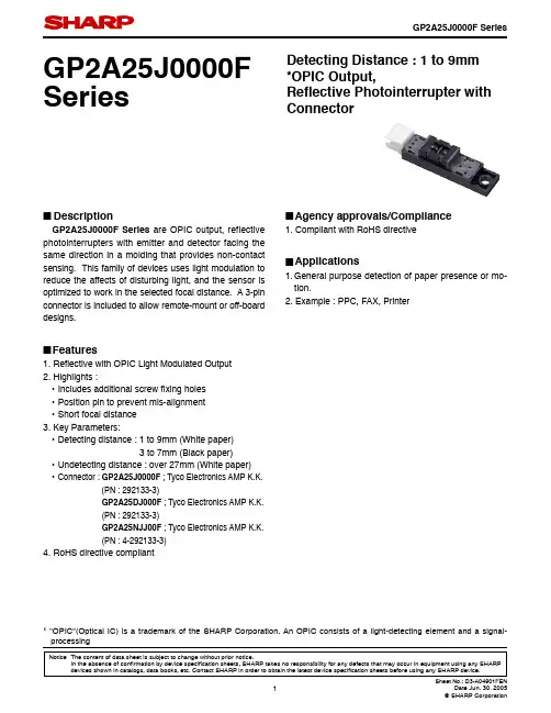
Notice The content of data sheet is subject to change without prior notice.In the absence of con fi rmation by device speci fi cation sheets, SHARP takes no responsibility for any defects that may occur in equipment using any SHARP GP2A25J0000F SeriesDetecting Distance : 1 to 9mm *OPIC Output, Re fl ective Photointerrupter with Connector■DescriptionGP2A25J0000F Series are OPIC output, reflective photointerrupters with emitter and detector facing the same direction in a molding that provides non-contact sensing. This family of devices uses light modulation to reduce the affects of disturbing light, and the sensor is optimized to work in the selected focal distance. A 3-pin connector is included to allow remote-mount or off-board designs.■Features1. Re fl ective with OPIC Light Modulated Output2. Highlights :• Includes additional screw fi xing holes • Position pin to prevent mis-alignment • Short focal distance 3. Key Parameters:• Detecting distance : 1 to 9mm (White paper) 3 to 7mm (Black paper)• Undetecting distance : over 27mm (White paper) • Connector : GP2A25J0000F ; Tyco Electronics AMP K.K. (PN : 292133-3) GP2A25DJ000F ; Tyco Electronics AMP K.K. (PN : 292133-3) GP2A25NJJ00F ; Tyco Electronics AMP K.K. (PN : 4-292133-3)4. RoHS directive compliant■Agency approvals/Compliance1. Compliant with RoHS directive■Applications1. General purpose detection of paper presence or mo-tion.2. Example : PPC, FAX, Printer* "OPIC"(Optical IC) is a trademark of the SHARP Corporation. An OPIC consists of a light-detecting element and a signal-processing■Internal Connection Diagram■Outline Dimensions(Unit : mm)V CC V OUT GNDDate code (2 digit)1st digit2nd digit Year of production Month of production A.D.Mark Month Mark 2000011 2001122 2002233 2003344 2004455 2005566 2006677 2007788 2008899 2009910X 2010011Y ::12Zrepeats in a 10 year cycleCountry of originJapan■Absolute Maximum Ratings■Electro-optical Characteristics (T a=25˚C)Parameter Symbol Rating UnitSupply voltage V CC−0.5 to +7VOutput voltage V O30V*1 Output current I OL50mA*2 Operating temperature T opr−10 to +60˚C*2 Storage temperature T stg−20 to +80˚C∗1 Sink current refer to Fig.5.∗2 The connector should be plugged in/out at normal temperature.(T a=25˚C) Parameter Symbol Condhitions MIN.TYP.MAX.Unit Supply voltage V CC− 4.75− 5.25V Current dissipation (I)I CC Smoothing value V CC=5V, R L=∞−−30mA *3 Current dissipation (II)I CCP Pulse peak value V CC=5V−−150mA Low level output voltage V OL V CC=5V, I OL=16mA, at detecting time−−0.4V High level output voltage V OH V CC=5V, R L=1kΩ, at non detecting time 4.5−−V*4 Non detection distance L LHL KODAK Gray Cards, V CC=5V−−27mm*4 Detection distance L HLSKODAK Gray Cards, V CC=5V−−1mm Black paper, V CC=5V−−3L HLLKODAK Gray Cards, V CC=5V9−−mm Black paper, V CC=5V7−−*5 Response time t PLHV CC=5V−−1ms t PHL−−1ms*6 Acceptable illuminance Ev1−3 000−−lx Ev2 1 500−−lx∗3 Refer to Fig.1.∗4 Refer to Fig.2.∗5 Refer to Fig.3.*6 Refer to Fig.4.Refl ective object Black paper (black) : Standard refl ective object (provided by SHARP Corporation) KODAK Gray Cards (use the white side refl ects about 90%):Standardrefl ective object (provided by SHARP Corporation) PPC paper : Standard refl ective object (provided by SHARP Corporation)Fig.2 Test Condition for Detecting Distance CharacteristicsV OHV OLLHS LHLO u t p u t V ODetection surfaceFig.1 Test Condition for Peak Pulse Value I CCPV O GNDμs W sV CC =5V L =1k ΩFig.3 Test Circuit for Response TimeV O GNDV V CC =5V Reflective objectWithout reflective objectE V1 : At non-detectingE V2 : At detectingIlluminance shall be that on the emission/detection surface. Output shall not go from "H" to "L".Light source A PhotointerrupterFig.4 Test Condition for External Disturbing Light IlluminanceFig.5 Low Level Output Current vs. Ambient TemperatureFig.6 Low Level Output Voltage vs. Ambient Temperature6050403020100L o w l e v e l o u t p u t c u r r e n t I O L (m A )27Low level output current I OL (mA)L o w l e v e l o u t p u t v o l t a g e V O L (V )0.010.1Supply voltage V CC (V)Remarks : Please be aware that all data in the graph are just for reference and not for guarantee.■Design Considerations●Design guide1) V O terminal : Open collector outputThis product operates the light emitter by pulse drive. Please supply the stable supply voltage in order to prevent error operation by pulse current.Please use this device after connecting a capacitor between V O and GND for prevention of line noise.2) Prevention of detection errorPlease be careful that you need to keep the direct inverter light away from the photo detecting surface since the device will not operate correctly in such case.In addition, we recommend to make sure the operation test in the actual application.3) Plugging in/outThe connector should be plugged in/out at normal temperature.This product is not designed against irradiation and incorporates non-coherent IRED.●PartsThis product is assembled using the below parts.• Photodetector (Q'ty : 1) [Using a silicon photodiode as light detecting portion, and a bipolar IC as signal processing circuit]Category Maximum Sensitivitywavelength (nm)Sensitivitywavelength (nm)Response time (μs)Photo diode900700 to 1 200400• Photo emitter (Q'ty : 1)Category Material Maximum light emittingwavelength (nm)I/O Frequency (MHz)Infrared emitting diode(non-coherent)Gallium arsenide (GaAs)9500.3 • MaterialCase Lens Bottom cover GP2A25J0000FBlack polyphernylene Sulfi de resin (UL94 V-0)Acryl resin(UL94 HB)Polycarbonate resin (Black) (UL94 V-2)GP2A25DJ000J Polycarbonate resin (Black) (UL94 V-2) GP2A25NJJ00F∗Polycarbonate resin (Black) (UL94 V-2)∗The IR-90 fi lter (Fuji Photo Film Co., Ltd.) is inserted between case and detector side lens.• OthersLaser generator is not used.■Manufacturing Guidelines●Cleaning instructionsPolycarbonate resin is used as the material of the lens surface. So this product shall not be cleaned by cleaning solvent absolutely. Dust and stain shall clean by air blow, or shall clean by soft cloth.●Presence of ODCThis product shall not contain the following materials.And they are not used in the production process for this product.Regulation substances : CFCs, Halon, Carbon tetrachloride, 1.1.1-Trichloroethane (Methylchloroform)Specifi c brominated fl ame retardants such as the PBBOs and PBBs are not used in this product at all.This product shall not contain the following materials banned in the RoHS Directive (2002/95/EC).•Lead, Mercury, Cadmium, Hexavalent chromium, Polybrominated biphenyls (PBB), Polybrominateddiphenyl ethers (PBDE).■Package specifi cation●Case packagePackage materialsAnti-static plastic bag : PolyethtyleneMoltopren : UrethanePacking case : Corrugated fi berboardPackage method100 pcs of products shall be packaged in a plastic bag, Ends shall be sealed by stapler. The bottom ot the packing case is covered with moltopren, and 2 plastic bags shall be put int the packing case.Moltopren should be located after all product are settled (1 packing conteains 200 pcs).Packing composition■Important Notices· The circuit application examples in this publication are provided to explain representative applications of SHARP devices and are not intended to guarantee any circuit design or license any intellectual property rights. SHARP takes no responsibility for any problems related to any intellectual property right of a third party resulting from the use of SHARP's devices.· Contact SHARP in order to obtain the latest device specification sheets before using any SHARP device. SHARP reserves the right to make changes in the specifi cations, characteristics, data, materials, structure, and other contents described herein at any time without notice in order to improve design or reliability. Manufacturing locations are also subject to change without notice.· Observe the following points when using any devices in this publication. SHARP takes no responsibility for damage caused by improper use of the devices which does not meet the conditions and absolute maximum ratings to be used specifi ed in the relevant specifi cation sheet nor meet the following conditions:(i) The devices in this publication are designed for use in general electronic equipment designs such as:--- Personal computers--- Offi ce automation equipment--- Telecommunication equipment [terminal]--- Test and measurement equipment--- Industrial control--- Audio visual equipment--- Consumer electronics(ii) Measures such as fail-safe function and redundant design should be taken to ensure reliability and safety when SHARP devices are used for or in connection with equipment that requires higher reliability such as:--- Transportation control and safety equipment (i.e., aircraft, trains, automobiles, etc.)--- Traffi c signals--- Gas leakage sensor breakers--- Alarm equipment--- Various safety devices, etc.(iii) SHARP devices shall not be used for or in connection with equipment that requires an extremely high level of reliability and safety such as:--- Space applications--- Telecommunication equipment [trunk lines]--- Nuclear power control equipment--- Medical and other life support equipment (e.g., scuba).· If the SHARP devices listed in this publication fall within the scope of strategic products described in the Foreign Exchange and Foreign Trade Law of Japan, it is necessary to obtain approval to export such SHARP devices.· This publication is the proprietary product of SHARP and is copyrighted, with all rights reserved. Under the copyright laws, no part of this publication may be reproduced or transmitted in any form or by any means, electronic or mechanical, for any purpose, in whole or in part, without the express written permission of SHARP. Express written permission is also required before any use of this publication may be made by a third party.· Contact and consult with a SHARP representative if there are any questions about the contents of this publication.。
approval的用法及短语一、approval的用法及意思Approval这个词是由approve这个动词所衍生而来,它通常表示"同意、批准或赞成"的意思。
在不同的语境中,approval可以作为名词或形容词使用。
下面将详细介绍approval在不同场景中的用法及短语。
1. 正式用途Approval作为名词时,常用于正式场合,特别是在商务和法律文书上。
比如,在提交报告或申请文件时,我们可以写上“Subject to the approval of the board”(经董事会批准后)。
这种表达方式体现了尊重权威并进行决策的流程。
2. 政府批准在政府相关事务中,approval通常用于描述政府机构对某个项目、计划或提案的批准过程。
例如,我们可以说"The construction project received government approval"(该建设项目已获得政府批准)。
这种使用方式强调了遵守有关规定以确保合法性和合规性。
3. 人际交往Approval也可指人们彼此之间的肯定、认可或称赞。
有些短语可以更好地表达此类含义。
- Seek/get/appreciate someone's approval (寻求/获得/欣赏某人的认同)- Winning someone's approval (赢得某人的认可)这些短语突出了个体在社交和亲密关系中寻求他人认可的情感层面。
4. 决策过程中的批准在组织内部或企业决策制定过程中,approval也是一个常见的用词。
一些相关表达包括:- Management approval (管理层批准)- Budget approval (预算批准)这些术语强调了决策者进行权衡和评估后作出的批准决策。
二、approval相关短语除了以上介绍的用法外,还有一些与approval相关的常用短语,下面将详细解释它们及其用法。

ICCP工作原理ICCP(Impressed Current Cathodic Protection)是一种广泛应用于金属结构防腐蚀的技术,它通过电流的作用来保护金属结构免受腐蚀的侵害。
ICCP工作原理涉及到电化学反应和电流的控制。
1. 电化学反应原理:ICCP利用电流将金属结构的电位调整到一个更负的值,使其成为一个阴极,从而抑制金属的氧化反应。
这种电流通过外部电源供应,通过阳极引入金属结构,使阳极上发生氧化反应,而金属结构则成为阴极,发生还原反应。
这种电化学反应称为阴极保护反应。
2. 电流控制原理:ICCP系统中的外部电源通过控制器提供电流,以保持金属结构的电位在一个安全的范围内。
控制器根据金属结构的特性和环境条件,调整电流的大小和方向,以实现最佳的防腐蚀效果。
通常,ICCP系统还配备了监测设备,用于实时监测金属结构的电位和电流,以便及时调整电流的参数。
3. ICCP系统的组成部份:ICCP系统主要由以下几个组成部份构成:- 外部电源:通常是一个直流电源,用于提供所需的电流。
- 阳极:通常是一种耐腐蚀的金属材料,如铝或者铜。
- 控制器:用于调整电流的大小和方向,并监测金属结构的电位和电流。
- 监测设备:用于实时监测金属结构的电位和电流,以便及时调整电流的参数。
- 接地系统:用于将电流引入金属结构,通常是通过接地极或者接地网实现。
4. ICCP系统的工作过程:ICCP系统的工作过程可以简述如下:- 外部电源提供电流,并通过控制器调整电流的大小和方向。
- 电流通过阳极引入金属结构,并在金属结构上发生氧化反应。
- 金属结构成为阴极,发生还原反应,从而抑制了金属的氧化反应。
- 监测设备实时监测金属结构的电位和电流,以便及时调整电流的参数。
- ICCP系统持续工作,保护金属结构免受腐蚀的侵害。
5. ICCP系统的应用领域:ICCP技术广泛应用于各种金属结构的防腐蚀,包括船舶、海洋平台、桥梁、油气管道、储罐等。

approval的用法和搭配A Brief Overview of the Usage and Collocation of "Approval"Introduction:Approval is a versatile word that finds application in various contexts. Understanding its usage and collocation is crucial for effective communication. This article aims to explore the different ways the term "approval" can be used and identify appropriate collocations to enhance your language proficiency.I. Approval as an Action or Process:1. Seeking Approval:Seeking approval is a common practice in many situations, both personal and professional. Whether submitting a proposal, making a significant life decision, or seeking validation from others, we often desire approval.2. Granting Approval:Granting approval highlights the power to give consent or endorsement to someone or something. It implies agreement or the acknowledgment of validity concerning a specific proposal, plan, or action.3. Receiving Approval:Receiving approval signifies that one's actions or proposals have earned acceptance or agreement from others. It fosters confidence and affirms one's competence and capabilities.II. Collocations with "Approval":1. Official/ Formal Approval:Official or formal approval refers to consent granted by authoritative entities such as government bodies, management boards, or religious institutions. Examples includeobtaining planning permission for construction projects or patent approvals for new inventions.2. Implicit/ Implied Approval:Implicit or implied approval indicates consent without explicit verbal expression but through actions, nonverbal cues, body language, etc. Such approvals often occur in interpersonal relationships when individuals understand each other's perspectives without explicitly saying so.3. Unanimous Approval:Unanimous approval suggests complete agreement among all parties involved in decision-making processes or judgments on a particular matter. It signifies consensus and commonly occurs in legal systems during jury deliberations.4. Public/ Popular Approval:Public or popular approval suggests widespread support from a large group within society towards an individual, idea, policy, product, etc., based on their favorable opinion expressed through surveys, polls, or social media.5. Disapproval:Disapproval, the opposite of approval, implies disagreement, dissatisfaction, or opposition toward someone or something. It indicates a lack of endorsement or validation.6. Self-Approval:Self-approval refers to being content and satisfied with one's own actions, decisions, or achievements without seeking external validation. Cultivating self-approval promotes self-confidence and independence.III. Expressions and Structures with "Approval":1. Approval Rating:An approval rating is a quantitative measurement indicating the level of support or acceptance people have towards a political leader, government policies, organizations, etc. This measurement helps gauge public opinion and sentiment.2. Gain/Win Approval:To gain or win approval involves undertaking specific actions that resonate positively with others' expectations to secure their agreement or endorsement.3. With/Without Approval:Using "with" or "without" before approval emphasizes whether consent was granted prior to an action: proceeding with approval signifies endorsement while proceeding without approval implies acting against it.4. Subject to ApprovalThe phrase "subject to approval" indicates that an action or decision is contingent upon receiving consent from relevant authorities or decision-makers before becoming finalized.IV. Phrases and Idioms Related to "Approval":1. Seek Someone's Stamp of Approval:This idiom suggests actively seeking someone's affirmation, endorsement, or support for an idea, project, plan, etc., emphasizing the person's influential role in giving consent.2. Give Something/Something Your Seal of Approval:This phrase metaphorically portrays the act of giving something one's seal/signature as a symbol of wholehearted endorsement for its excellence or quality.Conclusion:Understanding the various ways in which "approval" can be used and identifying appropriate collocations enhances our communication skills significantly. From seeking personal validation to securing formal consent for official matters, knowing how toexpress different shades of approval helps convey our intentions effectively while fostering positive relationships.。
ICCP工作原理ICCP(Intelligent Computer Control Program)是一种基于计算机智能控制程序的工作原理。
它是一种先进的自动化控制系统,广泛应用于电力、石油、化工、交通等领域。
ICCP系统通过采集、处理和分析实时数据,实现对各种设备和过程的智能监控和控制。
ICCP系统的工作原理可以分为以下几个步骤:1. 数据采集:ICCP系统通过传感器、监测设备等实时采集各种数据,包括温度、压力、流量、电流、电压等参数。
这些数据通过通信网络传输到ICCP系统的数据采集模块。
2. 数据处理:ICCP系统的数据采集模块将采集到的数据进行处理,包括数据清洗、校验、压缩等操作。
处理后的数据被存储在ICCP系统的数据库中,以备后续分析和控制使用。
3. 数据分析:ICCP系统的数据分析模块对采集到的数据进行实时分析和处理。
通过使用各种算法和模型,ICCP系统能够识别潜在的问题、异常情况和趋势变化。
数据分析结果可以匡助运维人员及时发现问题,并采取相应的措施进行调整和优化。
4. 控制指令生成:基于数据分析的结果,ICCP系统的控制指令生成模块会生成相应的控制指令。
这些指令可以是自动化的,也可以是由运维人员手动输入的。
控制指令包括对设备的开关、调节参数等操作。
5. 控制执行:ICCP系统的控制执行模块将生成的控制指令发送到相应的设备或者过程中。
通过与设备的接口进行通信,ICCP系统能够实现对设备的远程控制和调节。
控制执行模块还会监测设备的状态和反馈信息,以确保控制指令的正确执行。
6. 监控和报警:ICCP系统的监控和报警模块实时监测设备和过程的状态,并根据预设的规则和条件生成相应的报警信息。
报警信息可以通过各种方式传达给相关人员,以便及时采取措施,防止事故和故障的发生。
7. 数据可视化:ICCP系统的数据可视化模块将采集到的数据、分析结果和报警信息以图表、曲线、报表等形式展示出来。
这样,运维人员可以直观地了解设备和过程的运行情况,及时做出决策和调整。
PRODUCT SAFETY TRAINING FORnew draftsman所有信息均来源于安规Refer to Product Safety Folder in Lotus Notes.Inlets器具输入插座34Cable standards and approvals电线标准和认证3Plug standards and approvals插头标准和认证32Basic Rules of Power cords 电源线基本规则1ContentsTypes of Power Supply CordsClassifications & DefinitionsClass 1 -cord set or power cord intended for appliance with Earth Leak Protection (with earth pin)Class 2 -cord set or power cord intended for appliance with double-insulated protection (without earth pin)Cord set -Assembly consisting of one flexible cable fitted with one plug and one single connector, intended for the connection of an electrical appliance to the electrical supply (IEC60884-1:2006) Rewritable plug/connector -Plug/connector so constructed that the flexible cable can be replaced (IEC60884-1 / IEC60320-1)Non-rewirable plug/connector -Plug/connector so constructed that it forms a complete unit with the flexible cable afterconnection and assembly by the manufacturer of the plug orconnector (IEC60884-1 / IEC60320-1)Types of Power cordNon-detachable Power Cord Power Cord with customized end treatment and is meant to be joint to the appliance electric circuit board permanently. Theconsumers are not ableto remove the powercord from the appliancesDetachablePower CordPower Cord withappliance connectorand can be removedfrom the appliances bythe consumers.TypesPower Supply Cords A jumper cord is a detachable cord set. It is a cable fitted at end with a plug connector. This is often used to supply power from the computer Central Processing Unit (CPU) to the monitor.Free ends for direct soldering to aPrinted circuit boardTerminal and GrommetCLASSIFICATIONClass 1A Class 1 power cord is one which has an earth pin or earthconnection in addition to the usual live and neutral pins.(with earth pin) Class 2A Class 2power cord has the live and neutral pins only. Typically it isa 2 pins plug(without earth pin)Types of cable PVC电线橡胶线棉纱线Process of connector打端穿套注塑12345Strip outer jacket Crimp blades to wire Neutral / Earth / Live Insert crimped terminal intohousing Conn. over moldStrip inner insulation 脱皮Process of plug5Strip outer jacket Strip inner insulationCrimp blades to wireNeutral / Earth / Live Insert crimped terminal into housingPlug over mold1342General rules for cord setGeneral rules for cord set (Plug + Connector) Current rating of cable same or greater than connectorCurrent rating of plug same or greater than connectorClass 1 plug with Class 1 connector (Class 2 connector possible under some countries example UK, SG, MAL, SA, HK)Class 2 plug only with Class 2 connector (Exception Japan)Cord sets with 10A C13, C15 or C17 connectors shall not exceed 2m in length if fitted with conductor size of 0.75mm2Cord sets with 2.5A C7 connector shall not exceed 2m in length if fitted with conductor size of 0.5mm2Cord sets with 16A C19 connector shall not exceed 2m in length if fitted with conductor size of 1.0mm2Tinning 和SolderingCompare Tinning Soldering TinningSoldering pot返回目录Australia/New Zealand –AS/NZS 3112 (SAA)澳大利亚/新西兰-AS/NZS 3112(SAA)Austria –ONORM E 6623/6624 (OVE)澳地利-ONORM E6623/6624(OVE)Argentina –IRAM 2063, IRAM 2073 &IEC60884-1 (IRAM)阿根廷-IRAM 2063,IRAM 2073&IEC60884-1(IRAM)Belgium –NBN C 61-112-1 (SGS-CEBEC)比利时-NBN C61-112-1 (SGS-CEBEC)Brazil –NBR 14136 & NBR 6147 (TUV, UL & BV)巴西-NBR 14136&NBR 6147 (TUV,UL&BV)Cambodia –CS0017 (ISC)柬埔寨-CS0017(ISC)Canada –CSA 22.2 #42 (CSA or cUL)加拿大-CSA 22.2#42(CSA或UL)Chile (non-mandatory) –CEI 23-50 (IMQ or CESMEC)智利(不强制)-CEI 23-50(IMQ或CESMEC)China –GB1022 & GB2099.1 (CCC)中国-GB1022&GB2099.1(CCC)Certification is mandatory for plugs, cables and connectors as well as the whole cord set by CCCDenmark –SB 107-2-D1 (UL-DEMKO)丹麦-SB 107-2-D1(UL-DEMKO)Finland –SFS 5610 (FIMKO)芬兰-SFS 5610(FIMKO) France (non-mandatory) –NF C61-307 & NF EN50075 (LCIE)法国(不强制)-NF C61-307&NF EN50075(LCIE)Germany –DIN VDE 0620-101 (VDE)德国-DIN VDE 0620-101(VDE)Hong Kong (compliance) –BS 1363-1, BS 546 or EN50075 (Intertek, BSI, KEMA etc…)香港(符合性)-BS 1363-1,BS546或EN 50075(Intertek,BSI,KEMA等) India (non-mandatory) –IS1293 (BIS)印度(不强制)-IS1293(BIS)Israel –SI 32 (SII)以色列-SI 32(SII)Italy –CEI 23-50 (IMQ)意大利-CEI 23-50(IMQ)Korea –K60884-1 & KS C 8305 (KSA or KETI)韩国-K60884-1&KSC 8305(KSA或KETI)Malaysia (non-mandatory) –MS 589, MS 1577 or MS 1578 (SIRIM)马来西亚(不强制)-MS 589,MS 1577或MS1578(SIRIM)Mexico –NOM-003-SCFI-2000 (NOM or UL)墨西哥-NOM-003-SCFI-2000(NOM或UL)Netherlands –NEN 1020 (KEMA)荷兰-NEN 1020(KEMA)Norway –NEK 502 (NEMKO)挪威-NEK 502(NEMKO)Philippines –PNS 1486-1 & PNS 1572 (BPS)菲利宾-PNS 1486-1&PNS 1572(BPS)Russia (non-mandatory) –GOST R5132(GOST)俄罗斯(不强制)-GOST R5132(GOST)Saudi Arabia (non-mandatory) –SASO 2203 or SASO 2204 (CoC from ICCP)沙特阿拉伯(不强制)-SASO 2203或SASO 2204(由ICCP发出的CoC)Singapore –SS 145-1 or SS 472 (SPRING) 新加坡-SS 145-1或SS 472(SPRING)South Africa (non-mandatory) –SANS 164-1 & SANS 60799 (SABS)南非(不强制)-SANS 164-1&SANS 60799(SABS)Spain (non-mandatory) –UNE 20315 or UNE EN 50075 (AENOR)西班牙(不强制)-UNE 20315或UNE EN 50075(AENOR)Sweden –SS 428 08 34 (Intertek SEMKO)瑞典-SS 428 08 34(Intertek SEMKO)Switzerland –SN SEV 101 (SEV)瑞士-SN SEV 101(SEV)Thailand (non-mandatory) –TIS 166 (TISI)泰国(不强制)-TIS 166(TISI)Turkey (non-mandatory) –TS 40 (TSE)土耳其(不强制)-TS40(TSE)Uruguay (non-mandatory) –UNIT 821 & UNIT-IEC 884 (UNIT)乌拉圭(不强制)-UNIT 821&UNIT-IEC 884(UNIT)USA –UL498 & UL817 (UL, CSA-NRTL or Intertek)United Kingdom –BS 1363-1 or BS546 (BSI, Asta-Intertek, KEMA-BS or NEMKO-BS)英国-BS 1363-1或BS546(BSI,ASTA-Intertek,KEMA-BS 或NEMKO-BS)All EU countries may also use EN50075 (2.5A class 2) plug with ENEC mark issued by any EU test houses.欧洲各国对适用EN50075标准的2.5A插头可使用由欧洲认可测试机构发出的ENEC 标志.Connectors and EN50075 plug may use ENEC mark for whole of EU (including UK).Cable may use HAR mark for whole of EU (including UK) but this can only be obtained by EU manufacturers. ◄HAR►Japanese:Certification is mandatory for plug, cable and connector by PSE.Certification for plug is mandatory for UK and Singapore.Hong Kong will accept certification from any recognized laboratory.Certification is mandatory for cord set and cable by UL or CSA in the US and Canada.SAA Certification is mandatory for plug, cable and connector.Countries requiring whole cord set certification are US, Canada, South Africa, China, South KoreaAustralia/New Zealand –AS/NZS 3191, AS/NZS 60227 or AS/NZS 60245 (SAA)澳大利亚/新西兰-AS/NZS 3191,AS/NZS 60227或AS/NZS 60245(SAA)Argentina –HD21, HD22, IEC 60227 or IEC 60245 (EU)阿根廷-HD21,HD22, IEC 60227 或IEC 60245(EU)Brazil –NBR 13249, NBR 14833 (rubber),IEC60227 or IEC60245 (INMETRO or any RCB)巴西-NBR 13249, NBR 14833(橡胶) IEC 60227 或IEC60245(INMETRO或任一RCB)Cambodia –CS0024 (ISC)柬埔寨-CS0024(ISC)返回目录Canada –UL62 or CSA 22.2 # 49 (CSA or cUL) 加拿大-UL62或CSA22.2#49(CSA或cUL)Chile (non-mandatory) –HD21, HD22,IEC60227 or IEC60245 (any RCB)智利(不强制)-HD21,HD22,IEC 60227或IEC 60245(或任一RCB)Europe –HD21 or HD22 (any HAR signatory lab)欧洲-HD21或HD22(任一由HAR认可实验室)Hong Kong (compliance) –BS6500, HD21,HD22, IEC60227 or IEC60245 (any RCB)香港(符合性认证)-BS6500,HD21,HD22,IEC60227或IEC60245(任一RCB)India –IS695 (BIS)印度-IS695(BIS)Israel –EU以色列-EUJapan –Electrical Appliance日本-电子设备Korea –K60227 or K60245 (KSA or KETI)韩国-K60227或60245(KSA或KETI)Malaysia (not mandatory) –MS136, BS6500, IEC60227 or IEC60245.马来西亚(不强制)-MS136,BS6500,IEC 60227或IEC 60245。
PRODUCT SAFETY TRAINING FORnew draftsman所有信息均来源于安规Refer to Product Safety Folder in Lotus Notes.Inlets器具输入插座34Cable standards and approvals电线标准和认证3Plug standards and approvals插头标准和认证32Basic Rules of Power cords 电源线基本规则1ContentsTypes of Power Supply CordsClassifications & DefinitionsClass 1 -cord set or power cord intended for appliance with Earth Leak Protection (with earth pin)Class 2 -cord set or power cord intended for appliance with double-insulated protection (without earth pin)Cord set -Assembly consisting of one flexible cable fitted with one plug and one single connector, intended for the connection of an electrical appliance to the electrical supply (IEC60884-1:2006) Rewritable plug/connector -Plug/connector so constructed that the flexible cable can be replaced (IEC60884-1 / IEC60320-1)Non-rewirable plug/connector -Plug/connector so constructed that it forms a complete unit with the flexible cable afterconnection and assembly by the manufacturer of the plug orconnector (IEC60884-1 / IEC60320-1)Types of Power cordNon-detachable Power Cord Power Cord with customized end treatment and is meant to be joint to the appliance electric circuit board permanently. Theconsumers are not ableto remove the powercord from the appliancesDetachablePower CordPower Cord withappliance connectorand can be removedfrom the appliances bythe consumers.TypesPower Supply Cords A jumper cord is a detachable cord set. It is a cable fitted at end with a plug connector. This is often used to supply power from the computer Central Processing Unit (CPU) to the monitor.Free ends for direct soldering to aPrinted circuit boardTerminal and GrommetCLASSIFICATIONClass 1A Class 1 power cord is one which has an earth pin or earthconnection in addition to the usual live and neutral pins.(with earth pin) Class 2A Class 2power cord has the live and neutral pins only. Typically it isa 2 pins plug(without earth pin)Types of cable PVC电线橡胶线棉纱线Process of connector打端穿套注塑12345Strip outer jacket Crimp blades to wire Neutral / Earth / Live Insert crimped terminal intohousing Conn. over moldStrip inner insulation 脱皮Process of plug5Strip outer jacket Strip inner insulationCrimp blades to wireNeutral / Earth / Live Insert crimped terminal into housingPlug over mold1342General rules for cord setGeneral rules for cord set (Plug + Connector) Current rating of cable same or greater than connectorCurrent rating of plug same or greater than connectorClass 1 plug with Class 1 connector (Class 2 connector possible under some countries example UK, SG, MAL, SA, HK)Class 2 plug only with Class 2 connector (Exception Japan)Cord sets with 10A C13, C15 or C17 connectors shall not exceed 2m in length if fitted with conductor size of 0.75mm2Cord sets with 2.5A C7 connector shall not exceed 2m in length if fitted with conductor size of 0.5mm2Cord sets with 16A C19 connector shall not exceed 2m in length if fitted with conductor size of 1.0mm2Tinning 和SolderingCompare Tinning Soldering TinningSoldering pot返回目录Australia/New Zealand –AS/NZS 3112 (SAA)澳大利亚/新西兰-AS/NZS 3112(SAA)Austria –ONORM E 6623/6624 (OVE)澳地利-ONORM E6623/6624(OVE)Argentina –IRAM 2063, IRAM 2073 &IEC60884-1 (IRAM)阿根廷-IRAM 2063,IRAM 2073&IEC60884-1(IRAM)Belgium –NBN C 61-112-1 (SGS-CEBEC)比利时-NBN C61-112-1 (SGS-CEBEC)Brazil –NBR 14136 & NBR 6147 (TUV, UL & BV)巴西-NBR 14136&NBR 6147 (TUV,UL&BV)Cambodia –CS0017 (ISC)柬埔寨-CS0017(ISC)Canada –CSA 22.2 #42 (CSA or cUL)加拿大-CSA 22.2#42(CSA或UL)Chile (non-mandatory) –CEI 23-50 (IMQ or CESMEC)智利(不强制)-CEI 23-50(IMQ或CESMEC)China –GB1022 & GB2099.1 (CCC)中国-GB1022&GB2099.1(CCC)Certification is mandatory for plugs, cables and connectors as well as the whole cord set by CCCDenmark –SB 107-2-D1 (UL-DEMKO)丹麦-SB 107-2-D1(UL-DEMKO)Finland –SFS 5610 (FIMKO)芬兰-SFS 5610(FIMKO) France (non-mandatory) –NF C61-307 & NF EN50075 (LCIE)法国(不强制)-NF C61-307&NF EN50075(LCIE)Germany –DIN VDE 0620-101 (VDE)德国-DIN VDE 0620-101(VDE)Hong Kong (compliance) –BS 1363-1, BS 546 or EN50075 (Intertek, BSI, KEMA etc…)香港(符合性)-BS 1363-1,BS546或EN 50075(Intertek,BSI,KEMA等) India (non-mandatory) –IS1293 (BIS)印度(不强制)-IS1293(BIS)Israel –SI 32 (SII)以色列-SI 32(SII)Italy –CEI 23-50 (IMQ)意大利-CEI 23-50(IMQ)Korea –K60884-1 & KS C 8305 (KSA or KETI)韩国-K60884-1&KSC 8305(KSA或KETI)Malaysia (non-mandatory) –MS 589, MS 1577 or MS 1578 (SIRIM)马来西亚(不强制)-MS 589,MS 1577或MS1578(SIRIM)Mexico –NOM-003-SCFI-2000 (NOM or UL)墨西哥-NOM-003-SCFI-2000(NOM或UL)Netherlands –NEN 1020 (KEMA)荷兰-NEN 1020(KEMA)Norway –NEK 502 (NEMKO)挪威-NEK 502(NEMKO)Philippines –PNS 1486-1 & PNS 1572 (BPS)菲利宾-PNS 1486-1&PNS 1572(BPS)Russia (non-mandatory) –GOST R5132(GOST)俄罗斯(不强制)-GOST R5132(GOST)Saudi Arabia (non-mandatory) –SASO 2203 or SASO 2204 (CoC from ICCP)沙特阿拉伯(不强制)-SASO 2203或SASO 2204(由ICCP发出的CoC)Singapore –SS 145-1 or SS 472 (SPRING) 新加坡-SS 145-1或SS 472(SPRING)South Africa (non-mandatory) –SANS 164-1 & SANS 60799 (SABS)南非(不强制)-SANS 164-1&SANS 60799(SABS)Spain (non-mandatory) –UNE 20315 or UNE EN 50075 (AENOR)西班牙(不强制)-UNE 20315或UNE EN 50075(AENOR)Sweden –SS 428 08 34 (Intertek SEMKO)瑞典-SS 428 08 34(Intertek SEMKO)Switzerland –SN SEV 101 (SEV)瑞士-SN SEV 101(SEV)Thailand (non-mandatory) –TIS 166 (TISI)泰国(不强制)-TIS 166(TISI)Turkey (non-mandatory) –TS 40 (TSE)土耳其(不强制)-TS40(TSE)Uruguay (non-mandatory) –UNIT 821 & UNIT-IEC 884 (UNIT)乌拉圭(不强制)-UNIT 821&UNIT-IEC 884(UNIT)USA –UL498 & UL817 (UL, CSA-NRTL or Intertek)United Kingdom –BS 1363-1 or BS546 (BSI, Asta-Intertek, KEMA-BS or NEMKO-BS)英国-BS 1363-1或BS546(BSI,ASTA-Intertek,KEMA-BS 或NEMKO-BS)All EU countries may also use EN50075 (2.5A class 2) plug with ENEC mark issued by any EU test houses.欧洲各国对适用EN50075标准的2.5A插头可使用由欧洲认可测试机构发出的ENEC 标志.Connectors and EN50075 plug may use ENEC mark for whole of EU (including UK).Cable may use HAR mark for whole of EU (including UK) but this can only be obtained by EU manufacturers. ◄HAR►Japanese:Certification is mandatory for plug, cable and connector by PSE.Certification for plug is mandatory for UK and Singapore.Hong Kong will accept certification from any recognized laboratory.Certification is mandatory for cord set and cable by UL or CSA in the US and Canada.SAA Certification is mandatory for plug, cable and connector.Countries requiring whole cord set certification are US, Canada, South Africa, China, South KoreaAustralia/New Zealand –AS/NZS 3191, AS/NZS 60227 or AS/NZS 60245 (SAA)澳大利亚/新西兰-AS/NZS 3191,AS/NZS 60227或AS/NZS 60245(SAA)Argentina –HD21, HD22, IEC 60227 or IEC 60245 (EU)阿根廷-HD21,HD22, IEC 60227 或IEC 60245(EU)Brazil –NBR 13249, NBR 14833 (rubber),IEC60227 or IEC60245 (INMETRO or any RCB)巴西-NBR 13249, NBR 14833(橡胶) IEC 60227 或IEC60245(INMETRO或任一RCB)Cambodia –CS0024 (ISC)柬埔寨-CS0024(ISC)返回目录Canada –UL62 or CSA 22.2 # 49 (CSA or cUL) 加拿大-UL62或CSA22.2#49(CSA或cUL)Chile (non-mandatory) –HD21, HD22,IEC60227 or IEC60245 (any RCB)智利(不强制)-HD21,HD22,IEC 60227或IEC 60245(或任一RCB)Europe –HD21 or HD22 (any HAR signatory lab)欧洲-HD21或HD22(任一由HAR认可实验室)Hong Kong (compliance) –BS6500, HD21,HD22, IEC60227 or IEC60245 (any RCB)香港(符合性认证)-BS6500,HD21,HD22,IEC60227或IEC60245(任一RCB)India –IS695 (BIS)印度-IS695(BIS)Israel –EU以色列-EUJapan –Electrical Appliance日本-电子设备Korea –K60227 or K60245 (KSA or KETI)韩国-K60227或60245(KSA或KETI)Malaysia (not mandatory) –MS136, BS6500, IEC60227 or IEC60245.马来西亚(不强制)-MS136,BS6500,IEC 60227或IEC 60245。
SASO国际符合性认证计划(ICCP)是由沙特阿拉伯标准组织(SASO)自1995年起率先执行的一项对规定产品进行包含符合性评定、装船前验货及认证的综合计划,以保证进口的商品出运前能全面符合沙特的产品标CE标志是欧洲共同市场安全标志,是一种宣称产品符合欧盟相关指令的标识。
使用CE标志是欧盟成员对销售产品的强制性要求。
目前欧盟已颁布12类产品指令,主要有玩具、低压电器、医疗设备、电讯终端(电话类)、自动衡器、电磁兼容、机械等。
FCC是美国联邦通讯委员会的简称,它要求对所有在美国市场上销售的电子产品的电磁干扰进行强制性认证,因此FCC 认证是美国联邦法规规定必须获得的认证。
UL是美国保险商实验室,它是一个国际认可的安全检验及UL标志的授权机构,对机电包括民用电器类产品颁发安全保证标志。
部分UL安全标准被美国政府采纳为国家标准。
产品要行销美国市场,UL认证标志是不可缺少的条件。
GS标志是德国安全认证标志,它是德国劳工部授权由特殊的TUV法人机构实施的一种在世界各地进行产品销售的欧洲认证标志。
GS标志虽然不是法律强制要求,但是它确实能在产品发生故障而造成意外事故时,使制造商受到严格的德国(欧洲)产品安全法的约束,所以GS标志是强有力的市场工具,能增强顾客的信心及购买欲望,通常GS认证产品销售单价更高而且更加畅销。
FDA是美国食品及药品管理局的简称。
下设有DHHS部门,针对3类电子产品进行人体安全方面的控制: 1、激光类电子产品;2、微波类电子产品;3、X射线类电子产品.FDA是美国强制执行的认证之一,进入美国海关及在美销售的上述三类电子产品必须取得FDA的认可和授权。
CB制度是国际电工委员会(IECEE)建立的一套全球性互认制度,全球有34个国家的45个认证机构参加这一互认制度,这一组织的成员国及成员机构正在不断扩大。
企业从其中一个认证机构取得CB证书后,可以较方便地转换成其它机构的认证证书,由此取得进入相关国家市场的准入证。
SASO是英文Saudi Arabian Standards Organization的缩写,即沙特阿拉伯标准组织。
SASO负责为所有的日用品及产品制定国家标准,标准中还涉及度量制度,标识等。
事实上,SASO标准中有很多是在相关的国际电工委员会(IEC)等国际组织的的安全标准基础上建立的。
像很多其他的国家一样,沙特阿拉伯根据自己国家的民用及工业电压,地理及气候环境,民族宗教习惯等在标准中添加了一些特有的项目。
为了实现保护消费者的目的,SASO标准不只针对从国外进口的产品,对于在沙特阿拉伯本土生产的产品也同样适用。
宁波多美认证服务有限公司(Ningbo Dume Certification Services Co., Ltd.)简称DUME。
邻苯二甲酸盐认证办理热线:零伍柒四-八七一伍七二九七沙特阿拉伯工业及商务部及SASO要求所有SASO认证标准包含的产品在进入沙特海关时有SASO认证证书。
没有SASO证书的产品会被沙特港口海关拒绝入境。
ICCP计划为出口商或制造商获得CoC证书提供了三种途径,客户可根据自己产品的性质,符合标准的程度,以及出货的频繁程度选择最适宜的方式。
CoC证书由SAS O授权的SASO Country Office(SCO)或由PAI授权的PAI Country Office(PCO)办理签发。
SASO认证标准包含的产品:根据沙特阿拉伯标准组织的规定,SASO认证包含所有成人及儿童在住所,办公或娱乐场所使用的产品,所有机动车及零配件,以及建筑产品。
这些产品主要可以分为以下类别:空调、制冷设备、采暖设备电池化妆品玩具压缩机及风扇家用电子电器设备家用压力锅电线电缆传真机家用开关及断路器灯具及照明设备电梯及升降系统发动机办公用电子电器设备个人电脑电源电话机动车及零配件建筑产品、涂料等SASO认证的主要程序:生产商获取SASO认证,向沙特出口产品,需要以下几个步骤:向咨询公司提出申请,咨询公司根据产品类别,依照SASO的要求,向企业告知产品认证程序;企业依照认证程序提交产品样品进行检测,有些产品(如部分机动车及配件产品等)需要进行工厂检查;经产品检测合格后,企业获得SASO认证证书;如产品经检测不合格,企业将得到一份详细的说明报告;产品向沙特出口,货物入关时要出具SASO认证证书,沙特阿拉伯标准组织的技术人员将对证书进行检查;如不能出具SASO证书,产品将会被拒绝入境或抽样到沙特阿拉伯工业及商务部或沙特阿拉伯标准组织的实验室进行检测,如检测不合格,产品将会被拒绝入境,一切费用由出口企业承担。
CATHELCO: C-SHIELD ICCPMARINE IMPRESSED CURRENT CATHODIC PROTECTIONAPPROVAL DRAWINGS & INSTRUCTION MANUALCLIENT: KAUON SHIPYARD 57000 DWT BC VESSEL: KA101/ KA 102/ KA 103/TK101/TK102/TK103/TK104TK108CATHELCO REFERENCE: CA 35287/A-KRev: 0Issued: AIRDate: 19/07/07 MARINE HOUSE, HIPPER STREET SOUTH, CHESTERFIELD, DERBYS. S40 1SS, UK TEL: +44 (0)1246 246700. FAX: +44 (0) 1246 246701. E-MAIL: technical@C-SHIELDMARINE IMPRESSED CURRENTCATHODIC PROTECTION SYSTEMNOTES:a)Do not attempt to service or readjust the system operating levels without first readingand understanding this manual.b)The system operates at low d.c. voltage levels and may be severely damaged by highvoltage test equipment such as 500V Megger. Read the relevant section in this manual beforecarrying out any tests.c)Should any information be required which is not covered by this manual, please contactCathelco immediately. (Address on cover)C-SHIELD MANUAL INDEX:0.0 Scope of Supply0.1 List of drawings.1.0 Introduction.2.0 General Descriptions.3.0 Installation of Equipment.7.0 C-Shield Commissioning Check List.Section 0.0Page 1 of 1 SCOPE OF SUPPLYELLIPTICAL ANODES (FWD) WI-016REFERENCE CELLS (FWD) WI-008ELLIPTICAL ANODES (AFT) WI-016REFERENCE CELLS (AFT) WI-008SHAFT EARTHING SYSTEMWI-011POWER SUPPLY UNIT – THYRISTOR (AFT) WI-036POWER SUPPLY UNIT – THYRISTOR (FWD) WI-0361.0INTRODUCTION:1.0.1 PRINCIPLES OF CORROSION AND CATHODIC PROTECTION:Metallic corrosion is an electro-chemical reaction in which the metal combineswith a non metal, such as oxygen, to form a metal oxide or other compound.This depends upon the nature of the environment.Different metals have different tendencies to corrode, termed activity orpotential. These potentials can be tabulated and form the electro-chemicalseries.A more practical approach is the determination of the tendency of certain metalsto corrode in a particular electrolyte, such as sea water. This is termed thegalvanic series of which the following table is an abridged form.Active or AnodicMagnesiumZincMild SteelWrought IronCast IronNi-Resist18.8.3 % Molybdenum SS, Type 316 (Active)LeadTinManganese BronzeNaval BrassAluminium BronzeCopper70 Copper 30 NickelNickel (Passive)Monel, 70% Nickel - 30 % Copper18.8.3 % Molybdenum SS, Type 316 (Passive)Noble or CathodicNote Some metals and alloys have two positions in the series, marked Activeand Passive; the active position is equivalent to the position if corrosion isoccurring and approaches the electro-chemical series position for the material.The passive position relates to a non-corroding situation where the material isprotected by a self forming surface film. For example, type 316 stainless steel insea water is more likely to be passive than type 304 and is therefore generallypreferred for immersed marine applications.If two metals are placed in an electrolyte (e.g. sea water or damp soil) and are in direct electrical contact, a current will pass through the electrolyte from the more active metal onto the least active metal. The least active metal does not corrode and is termed the cathode. The more active metal, the anode, passes into solution and the flow of electrical current increases. This is a metal ion and electron transfer process i.e., it corrodes.This simple cell may be represented as:Figure 1.1 - Simple Corrosion CellThe Anodic and cathodic areas in a corrosion cell may be due to the electrical contact of two dissimilar metals, termed galvanic corrosion. Anodic and cathodic areas may be formed on a single metal surface as micro-cells for instance by rain drops on uncoated steel. Alternatively, they may be close but discrete cells found when accelerated corrosion occurs at uncoated Anodic areas on a generally coated cathodic structure. In addition there are long line type cells that occur on pipelines that pass through aggressive low resistivity soils. These sections form Anodic areas and corrode in preference to cathodic areas in less aggressive higher resistivity soils.Large currents can occur at small Anodic areas and lead to rapid corrosion of marine structures such as ship's internal tanks, external hull plates, sheet steel piling in harbours and tubular structures common in jetties and petrochemical drilling and production platforms.Cathodic Protection is a system of preventing corrosion by forcing all surfaces of a structure to be cathodes by providing external anodes.As described above, a galvanic corrosion cell occurs when dissimilar metals are in contact with each other within an electrolyte. Care should be taken in theconstruction of structures that will be buried or immersed in an electrolyte to ensure a galvanic cell is not created.Typical examples of galvanic cells are:a ) Steel or cast iron water boxes in contact with non ferrous (often copperbased) tube plates in condenser water boxes in ships or generatingplant. Rapid corrosion of the ferrous water box occurs close to the tubeplate.b) Brass or bronze valves fitted to immersed steel buoyancy tanks orflooding chambers on marine petrochemical structures. Acceleratedcorrosion of the steel occurs near the valve.c) The connection of steel pipes into an otherwise cast iron system.Accelerated corrosion of the steel occurs near the cast iron sections. Sacrificial anode cathodic protection achieves corrosion prevention on a particular structure or component by forming a galvanic cell where an additional anode of zinc, magnesium or aluminium corrodes in preference to the structure. The galvanic corrosion current (see simple cell before) available from this anode / electrolyte / structure combination should be sufficient to overcome the local surface corrosion currents on the structure until no current flows from Anodic areas of the structure i.e the structure is entirely cathodic or under complete cathodic protection.The potential, or measure of activity, between the structure and the electrolyte is a relatively easily measured indication of whether the structure is Anodic or cathodic. For steel under normal non anaerobic conditions it can be shown theoretically, and is accepted practically, that a steel/electrolyte potential more negative than -0.85 volts measured against a standard copper/copper sulphate electrode indicates that cathodic protection is achieved. This is equivalent to -0.80 volts measured against silver / silver chloride electrode and + 0.24 volts against a zinc electrode as indicated in figure 1.3.SACRIFICIAL ANODE CATHODIC PROTECTION:As indicated previously, a metal can be made cathodic by electrically connecting it to a more Anodic metal within the electrolyte. The most commonly used Anodic metals are alloys of aluminium, zinc and magnesium. Anodes of these metals corrode preferentially; the corrosion current of the anode achieving cathodic protection of the structure to which they are connected. The anodes deteriorate as an essential part of their function and they are therefore termed sacrificial.2.0DESCRIPTIONS:GENERAL2.1.1 IMPRESSED CURRENT CATHODIC PROTECTION:A metal also can be made cathodic by electrically connecting it to anothermetallic component in the same electrolyte through a source of direct electriccurrent and directing the current flow to occur off the surface of added metalliccomponent (anode), into the electrolyte and onto the metal (cathode). This caneasily be visualised by reference to the simple cell and assuming yet anotherelectrode with a power source is introduced and that the current flow from thiselectrode is sufficient to overcome the natural corrosion current.Because an external current source is employed, this type of protection istermed 'IMPRESSED CURRENT CATHODIC PROTECTION'.Figure 1.2 - Cathodic Protection Applied to a Simple Corrosion CellA source of direct current is required, this is generally obtained from mainspower units that contain a transformer and rectifier. The magnitude of thiscurrent may be automatically controlled in response to a continuous monitor ofthe cathode / electrolyte potential or may be manually controlled afterintermittent measurement.The impressed current anode material is ideally non-consumed by the passageof current from it into the electrolyte, in practice the materials used are acompromise between this ideal and the cost and physical properties of availablematerials. Impressed current anodes are made from graphite, silicon iron, leadalloys some with platinum bi-electrodes, platinised titanium or more exoticcombinations such as platinum clad niobium. The selection of the correct anodematerial is critical in the formulation of an effective and economic cathodicprotection scheme.Generally, for a given current demand, less impressed current anodes thansacrificial anodes are required for protection, as high anode currents arefeasible. Impressed current systems of cathodic protection are more sophisticated in design than sacrificial systems.Figure 1.3 - Comparison of Reference Electrodes & Interpretation2.2.0 MARINE IMPRESSED CURRENT SYSTEM:The C-Shield Marine Impressed Current System comprises the followingcomponents, as illustrated in figure 1.4.2.2.1 Impressed Current AnodesThe function of the anode is to conduct the d.c. protective current into the seawater. C-Shield anodes have been designed to perform this function whilstmaintaining a low electrical resistance contact with the sea water. Standardsurface mounted anodes are available with from 50 to 300 Ampere ratings. Forforward mounted systems and for special applications 50 and 75 Ampererecessed anodes are available.Materials now used by C-Shield for Anodes have now gone beyond lead alloywith specialist coated titanium based Anodes now available. All C-Shield anodedesigns utilise a tough, chlorine resistant, but slightly flexible plastic carrier.The use of a 24 volt system reduces the number and length of the anodes fromthat required with a 12 volt system. The increased anode/sea water resistanceresulting from this decrease in anode size is overcome by the additional voltage.Recommended cable sizes for various run lengths are tabulated in section 3.4.The potential of the hull steel to the sea water is unaffected by this increase indriving voltage, as the resistive effects are local to the anode and the hull/seapotential is a function of the current flow, the sea water and the coatingcondition, not the driving voltage.The electrical connections to the active surface are made at the back of theanode and are fully encapsulated and protected by the hull penetration.Recessed anodes of essentially similar construction are provided for bowsection applications.All hull penetrations are provided with substantial doubler plates and cofferdams. The penetrations themselves are made watertight with heavy dutypacking glands, the cofferdams are fully sealed and provided with watertightcable glands, all conforming to the requirements of Classification Societies.2.2.2 Impressed Current Reference Electrodes.The high purity, high stability, zinc reference electrodes are designed to give astable reference against which the hull/sea potentials can be measured and asmall current flow that is used in the closed loop circuit to maintain the pre-setlevels of protection.The construction and the quantity of zinc employed within the electrodes aresuch that a minimum life of fifteen years is available without maintenance orreplacement.The minimum number of reference electrodes per power supply is one althoughnormally two will be fitted. Ideally, these should be located a minimum of 7.5metres distant from the anodes. In the case of a stern only installation with theanodes more than 150 metres from the bows, one reference electrode may belocated in the bows.A novel feature of the C-Shield closed circuit is that additional reference cellsmay be placed at areas that may be susceptible to over-protection such asadjacent to the anode dielectric shields. These additional reference cells providea permanent check, thus preventing any coating damage due to over-protectionif conditions of operation change from those anticipated. This feature is offeredas an optional extra to the standard schemes.All hull penetrations are provided with substantial cofferdams. The penetrationsthemselves are made watertight with heavy duty packing glands. The cofferdams are fully sealed and provided with watertight cable glands allconforming to the requirements of the Classification Societies.2.2.3 Power Supply Unit:The C - Shield impressed current Cathodic protection power supply unit is athyristor system housed in a range of different sized cabinets. The specificpower supply unit supplied is illustrated on the drawing included with thismanual. The system comprises of a control PCB, a Thyristor PCB and aThyristor unit (consisting of a transformer, a choke and a thyristor bridge)ranging in size from 100 Amperes upto 800 Amperes. The supplyrequirements are 415 Vac +/-10%, three phase, 50/60 Hz.The control PCB is a micro-processor based system having a 2 line 16character backlit LCD display which is located in the top centre of thecabinet door. The display is used to monitor and allow control of thesystem. Below the LCD are four push buttons, which are the controls forchanging the system parameters. To the right of the LCD is a power onindicator, which also acts as an alarm indicator. On the reverse side are arotary switch and a potentiometer. The switch toggles between manualoverride and normal operation. This allows the operator, in the event of afault, to disable the micro-processor control system, and to control theoutput current with the potentiometer.DISPLAY:This allows the operator to control and monitor the running and setparameters of the system. It comprises of a 2 line 16 character backlit LCDdisplay, 4 push button switches and an Alarm LED. This is mounted on thedoor of the cabinet.MAIN CONTROL PCBThis board controls the operation of the system. It provides control signalsto the thyristor driver PCB, which allow control over the output current andvoltage of the system. This is mounted on the back of the cabinet door.PCBTHYRISTORThis board monitors and conditions the signals supplied to the thyristorunit.2.2.4 BondingTo enable the rudder to receive protection it is provided with a dedicatedelectrical bond in the form of a flexible cable from the top of the rudderstock to the main ship structure. In the same way any stabilisers are bondedto allow protective current to these surfaces.To allow protection of the bare propeller and any exposed shafting and toprevent electrical arcing between shaft and bearings the propeller shaft isfitted with a slipring assembly. A set of brushes provide the completion of alow resistance path to allow current to flow to the propeller blades alongthe shaft and back to the hull. The slipring is formed from a copper stripclamped around the shaft with high copper content heavy current capacitybrushes held in geared brush holders. The C-Shield slipring track is silverplated as standard and in addition silver graphite brushes are used tominimise contact resistance.3.0 INSTALLATION OF EQUIPMENT:3.0.01 Description:The C-Shield Impressed Current System consists of anodes and electrodesfor installation through the hull using penetration and cofferdamarrangements, a power supply unit for location internally and bondingarrangements for appendages such as propeller and rudder. The system usesidentical cofferdams for both surface mount linear and recessed anodes. Thecofferdams for the reference electrodes are longer than those for the anodesso that there is a necessity to differentiate between cofferdams beforestarting assembly.3.0.02 Locations for components are shown on the C-Shield drawings supplied forthe particular vessel, but are normally subject to final confirmation betweenthe C-Shield engineer on site and the yard/owner.3.0.03 It is very important that the installation instructions given are followed. Thebiggest cause of future problems found with the running of impressedcurrent systems is incorrect installation. Should any problems occur duringinstallation of this system or should any instruction appear unclear pleasecontact Cathelco for advice.3.3ELLIPTICAL RECESSED ANODE:3.3.01 Select the required area and mark out using a template the steelworklocation. Make sure that the internal stiffening will not be touched.Ensure the ellipse will be located within a steel plate and notinterfere with existing weld seams.3.3.02 Cut an elliptical hole. The ellipse may be easily marked out bypositioning the anode on the hull and scribing around it and allowinga margin of 6mm around the anode periphery. Alternatively, atemplate may be made using the doubler plate. Refer to drg. C1186.3.3.03 Clean the profile of the elliptical hole and grind a nominal 3mmradius on the outer edge and a weld preparation on the inner edge tomatch the one provided on the doubler plate3.3.04 Position the doubler plate internally and line it up with the ellipse.Tack weld the doubler plate in position. When you are sure that thedoubler plate is correctly located and that the anode will fit cleanlyinto the recess continuously weld the doubler plate to the inboard andoutboard surface of the hull plating. Grind the recess weld flush asshown.3.3.05 Place the cofferdam concentrically over the cable gland hole in therear of the doubler plate. Position the cable exit tube from thecofferdam to suit site conditions and weld internally and externally inposition with penetration welds with single bevel full penetrationweld complete with a backing run.3.3.06 Cover the anode holding studs with plastic tubing to prevent damagefrom shot blasting.3.3.07 Shot blast the doubler plate and recess to SA 2 1/2 minimum3.3.08 Fit a suitable cable gland into the doubler plate from the inboard sideinside the cofferdam recess.3.3.09 Mix equal quantities of the 2 part epoxy filler material supplied.Apply epoxy to back of anode and spread evenly.3.3.10 Prepare an Anode for installation. The dimensions of the Anode areshown by drg.C1202. Carefully insert the Anode Cable through thecentre hole in the doubler plate and through the cable gland takingcare not to damage the insulation. Locate the anode over the sixfixing points in the backing plate.3.3.11 Slowly draw anode into recess by tightening the Anode fixing nuts.The epoxy filler will slowly ooze out of the sides as anode settlesinto position, ensure the Anode cable does not become trapped.When anode is flush with hull and the bolts are resting within anodefixing point recess ensure the head of the holding nut is below the toplevel of the anode. Fill stud holes with epoxy and smooth level.3.3.12 Smooth epoxy at edge of anode so that gap between anode andsteelwork is completely filled.3.3.13 Inside the Ship fully tighten the gland onto the cable.3.3.14 Before proceeding further, ensure that all other welding work, eitherinboard or outboard, has been completed for the entire area to becovered by the di-electric shield. Any welding carried out after theapplication of the di-electric shield will damage the shield materialeven if the welding is not associated with the cathodic protectionsystem.3.3.15 The dimensions of the di-electric shield are shown on drg. C1196.3.3.16 Inspect the area to be covered and grind off all weld splatter, andsurplus weld material to a smooth profile.3.3.17 Remove all oil and grease from the area using clean, dry, oil free ragssoaked in a hydrocarbon solvent such as Xyol, Yoluene or whitespirit, do not use petrol or paraffin. Change the rags frequently toavoid merely spreading contamination.3.3.18 Ensure that the anode face is protected with masking tape or similar.Abrasive blast clean the entire area to a white metal finish, SA 2 1/2Swedish standard using grit or sand. Check the surface profile heightusing test tape and that it is within the range 50 - 70 micron.3.3.19 Form the primary di-electric shield by applying the anode epoxymastic within four hours of blasting and before the formation of anyvisible rust bloom. Fill the four threaded temporary anode retainingmounting holes with mastic. Technical details and health precautionsfor the anode mastic are available on request from Cathelco.3.3.20 Thoroughly mix the contents of each can before mixing the two partstogether. Follow the mixing instructions on the epoxy masticmaterial packs, using a power driven mixer if possible.3.3.21 Apply by trowel to produce a film 4mm thick at the edge of theanode surface tapering to 1mm thick at the shield edge. Form acircular shield of mastic of 900mm radius. A one coat application isessential.3.3.22 Ensure that the di-electric shield mastic covers the resin of the anodebut do not allow mastic on the metal anode face. Allow the mastic toharden fully before painting over. Remember to remove theprotective tape from the surface of the anode.3.3.23 Inside the ship, remove the blank flange from the cofferdam andcheck the cable for damage.3.3.24 Apply thread tape to the second anode cable gland, make sure theneoprene 'O' ring is fitted and pass the gland over the anode cable tofit it into position as detailed below. Tighten the main body fully intoposition, then tighten on to the cable.3.3.25 Dry Compartment Installation. Pass the cable through the side entryhole in the cofferdam and fit the cable gland in the same way asbefore, to the outside of the cofferdam, leaving slack cable betweeninner and outer glands.3.3.26 Fit the junction box at some convenient point adjacent to thecofferdam and connect the anode cable to the transformer/rectifiervia shipyard supply cable, see power supply unit instructions.3.3.27 Wet Compartment Installation. Pass the shipyard cable through theside entry hole into the cofferdam. Note that any cables running intanks should be in heavy wall conduit pipe. Fit the cable gland in thesame way as before, to the inside of the cofferdam side entry, overthe shipyard cable.3.3.28 Connect the anode cable tail to the shipyard cable internally in thecofferdam. Use a recognised splice kit or a C-Shield splice kit can beprovided. Refer to drg. M1043 for full instructions. Where cablesare spliced in a cofferdam it is recommended that the cofferdam befilled with paraffin wax or similar. Connect the shipyard cable to thepower supply unit.3.3.29 Check the insulation of the anode connection circuit to the hull usinga 500V earth insulation test meter. Note, if the anode is submergedthen this test will show a short circuit. Disconnect from power supplyunit before this test or permanent damage may occur.3.3.30 Make a final visual check of all connections and finally fit the blindflange and gasket to seal the cofferdam. Do not over paint the anodewhen painting over the dielectric shield area.3.3.31 Note all welds used during installation should meet the Yard orClassification Society rules.3.4 REFERENCE ELECTRODE CELLS3.4.01 Cut a 170mm diameter hole in the hull at each electrode location.This is to enable installation of the cell mounting cofferdam asshown by drawing C11903.4.02 Grind off any surplus metal to ensure that the cofferdam body willlocate flat to the internal shell plating at the inboard side of the hole.3.4.03 Locate the cofferdam centrally over the hole, inside the hull.3.4.04 Secure the cofferdam in the position by a continuous fillet weldinternally to give a weld section at least equal to the platingthickness. Drawing C1162 gives a rough guide for welding andelectrode cell installation.3.4.05 Clean off all weld splatter from the surfaces including the cofferdamrecess, and grind flat all welds in the area to be occupied by thereference electrode.3.4.06 Ensure that the neoprene sealing gasket is on the back of thereference electrode assembly and that the inside of the cofferdamrecess into which the electrode will fit is clean and dry.3.4.07 Apply thread tape or sealing compound to the M20 threadedmounting sleeve of the reference electrode. The reference electrodecell is shown by drawing C1102. Remove the nut, dished washer andneoprene washer from the M20 sleeve but leave the neoprene sealingring in place.3.4.08 From the outboard of the shell thread the cable through the glandplate at the back of the cofferdam recess.3.4.09 Apply sealing compound to the recess and screw the referenceelectrode firmly into place in the cofferdam using the spannerprovided to fit the recesses in the front face of reference electrodecarrier. Do not Over Tighten !!3.4.10 Inside the ship, remove the blank flange from the Cofferdam andcheck the cable insulation for any possible damage.3.4.11 On completion of the inspection caulk the gap between the referenceelectrode carrier and the outer shell with sealing compound, to leavea smooth uniform surface.3.4.12 From the inboard of the shell fit the neoprene washer within thedished steel washer and locate over the reference electrode mountingsleeve within the cofferdam. Ensure that the neoprene washer facesoutboard and is in contact with the gland plate in the cofferdam.3.4.13 Fit the M20 full locking nut on the reference electrode mountingsleeve and tighten until the neoprene washer is fully compressed andthe dished washer is in contact with the gland plate.3.4.14 Pass the cable through the side entry hole in the cofferdam.3.4.15 Dry Compartment Installation: Apply thread tape to the referenceelectrode cable gland, and pass the gland over the anode cable to fitit into position outside the cofferdam as shown in the drawing.Tighten the main body fully into position then tighten onto the cableleaving slack cable inside the cofferdam.3.4.16 Fit a junction box at some convenient point adjacent to thecofferdam and connect the reference electrode cable to the powersupply unit via shipyard supplied cable see the Power Supply Unitinstructions in section 3.53.4.17 Wet Compartment Installation: Pass the shipyard cable through theside entry hole into the cofferdam. Any cables, which run throughtanks, must be housed in heavy walled conduit pipe. Fit the cablegland in the same way as before but to the inside of the cofferdamover the shipyard cable.3.4.18 Connect the anode cable tail to the shipyard cable using a cablesplice kit. Use an industry recognised kit or a C-shield splice kit asshown by drawing M1043. After splicing in submerged cofferdams itis recommended that the cofferdam recess void be filled withparaffin wax or similar. Connect the shipyard cable to the PowerSupply Unit see section 3.53.4.19 Check installation of the reference connection circuit to the hullusing 500 Volt earth insulation meter. If the electrode is submergedthen this test will show a short circuit.Disconnect from the power supply unit before this test or permanentdamage may occur.3.4.20 Make a final visual check of all connections and finally fit the blindflange and gasket to seal the cofferdam.3.4.21 Please ensure that if the vessel is going to be stood in water for along period of time during the outfitting period, the reference cellsare NOT to be connected to panel until the ICCP system iscommissioned.。