A framework for designing deadlock-free wormhole routing algorithms
- 格式:pdf
- 大小:1.93 MB
- 文档页数:15

isight design gateway -回复iSight Design Gateway: Enhancing Creativity and InnovationIntroductionIn today's rapidly changing world, creativity and innovation have become critical for organizations to stay competitive. Companies are constantly looking for ways to enhance their ability to generate new ideas and solve complex problems. One tool that has emerged as a powerful catalyst for creativity is the iSight Design Gateway. In this article, we will explore the features and benefits of iSight Design Gateway, and how it can help organizations foster an environment of innovation.What is iSight Design Gateway?iSight Design Gateway is an advanced software platform that provides a collaborative workspace for idea generation, design thinking, and innovation. It acts as a centralized hub where team members can come together to share ideas, insights, and build upon each other's work. The platform integrates various tools and techniques, such as brainstorming, prototyping, and iterativedesign processes, to help teams develop innovative solutions and bring them to life.Features and Functionality1. Idea Management: iSight Design Gateway allows organizations to capture and manage ideas from various sources, including employees, customers, and partners. It provides a structured approach to idea generation, enabling teams to evaluate and prioritize ideas based on their potential impact and feasibility.2. Collaborative Workspace: The platform offers a virtual workspace where team members can collaborate in real-time, regardless of their physical location. It provides tools for sharing files, conducting virtual meetings, and facilitating discussions, fostering a collaborative environment that supports creativity and knowledge sharing.3. Design Thinking Tools: iSight Design Gateway incorporates design thinking methodologies into its framework. It provides tools for understanding user needs, prototyping ideas, and conducting user testing. By following a human-centered design approach,teams can create solutions that resonate with their target audience and offer meaningful experiences.4. Data Visualization and Analytics: The platform enables teams to analyze and visualize data from various sources to gain insights and inform decision-making. With interactive dashboards and robust analytics capabilities, organizations can make data-driven decisions, identify trends, and uncover opportunities for innovation.Benefits of iSight Design Gateway1. Enhanced Creativity and Innovation: iSight Design Gateway fosters a culture of innovation by providing a structured framework and collaborative tools for idea generation and design thinking. It encourages the free flow of ideas, promotes cross-functional collaboration, and enables teams to explore and experiment with new concepts.2. Increased Efficiency and Productivity: The platform streamlines the innovation process by centralizing all activities and resources in one place. It eliminates the need for manual documentation, reduces administrative tasks, and enables teams to focus oncreative problem-solving. By automating repetitive tasks, iSight Design Gateway saves time and boosts overall productivity.3. Improved Communication and Collaboration: With its virtual workspace and real-time collaboration features, iSight Design Gateway enables seamless communication among team members. It breaks down geographical and organizational barriers, facilitating knowledge sharing and fostering a sense of collective ownership in the innovation process.4. Better Decision-Making: The platform provides teams with data-driven insights and analytics, empowering them to make informed decisions. By visualizing data and analyzing trends, organizations can identify gaps, validate assumptions, and align innovation efforts with business goals, leading to more effective and successful outcomes.ConclusionInnovative organizations understand the importance of creating an environment that nurtures creativity and fosters a culture ofinnovation. iSight Design Gateway offers a comprehensive solution to enhance teamwork, streamline processes, and drive successful innovation outcomes. By integrating various tools and methodologies, iSight Design Gateway enables organizations to transform ideas into actionable solutions, stay ahead of the competition, and thrive in an ever-evolving business landscape.。
题目:dyna流固耦合不报错显示文件路径终止运算1. dyna流固耦合简介dyna是一种流行的有限元分析软件,常用于汽车、航空航天和工程领域的仿真分析。
流固耦合是dyna中的一个重要功能,用于模拟流体与固体的相互作用。
在仿真过程中,dyna会根据用户设定的参数进行计算,并输出相应的结果。
2. dyna流固耦合中的报错问题然而,在使用dyna进行流固耦合仿真时,一些用户可能会遇到报错的情况。
其中,最常见的问题之一就是在进行流固耦合计算时,dyna会显示文件路径终止运算的错误信息。
这使得用户无法顺利进行仿真分析,严重影响了工作效率和结果准确性。
3. dyna流固耦合不报错显示文件路径终止运算的解决方法为了解决这一问题,一些经验丰富的用户提出了一些解决方法,以下将分别介绍:3.1 检查输入文件用户需要仔细检查输入文件中的参数设置是否正确。
特别是在流固耦合的输入中,可能存在一些不合理的设定,导致dyna在计算过程中出现错误。
用户需要逐一检查输入文件中的相关参数,并确保其准确无误。
3.2 检查计算模型用户需要检查流固耦合的计算模型。
在一些情况下,模型中可能存在一些不合理的设定或者错误,导致dyna无法正确进行计算。
用户需要对计算模型进行仔细检查和排查,确保其中的参数和设置符合实际情况,并且能够顺利进行计算。
3.3 更新软件版本用户还可以尝试更新dyna的软件版本。
在一些旧版本的软件中,可能存在一些bug或者兼容性问题,导致流固耦合计算出现错误。
用户可以尝试下载最新版本的dyna软件,并进行更新。
在一些情况下,新版本的软件可能修复了一些旧版本存在的问题,使得流固耦合计算更加稳定和准确。
4. 结语dyna流固耦合不报错显示文件路径终止运算是一个比较常见的问题,但是通过一些简单的解决方法,用户可以很快地解决这一问题。
在使用dyna进行流固耦合仿真时,用户需要仔细检查输入文件和计算模型,并且可以尝试更新软件版本,以确保计算能够顺利进行。
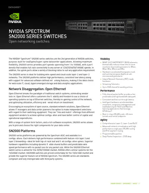
Visibility>WHAT JUST HAPPENED?® (WJH) telemetry dramatically reduces mean time to issue resolution by providing answers to: When, What, Who, Where and Why >Hardware-accelerated histograms track and summarize queue depths at sub-microsecond granularity >Inband Network Telemetry (INT)-ready hardware >Streaming Telemetry>Up to 256K shared forwarding entriesPerformance>Fully shared packet buffer provides a fair, predictable and high bandwidth data path >Consistent and low cut-through latency >Intelligent hardware-accelerated data movement, congestion management and load balancing for RoCE and Machine learning applications that leverage GPUDirect ® >Best-in-class VXLAN scale—6X more tunnels and tunnel endpointsAgility>Comprehensive Layer-2, Layer-3 and RoCE >Advanced network virtualization with high performance single pass VXLAN routing and IPv6 segment routing >Programmable pipeline>Deep Packet Inspection – 512B deepThe NVIDIA ® Spectrum ™ SN2000 series switches are the 2nd generation of NVIDIA switches, purpose-built for leaf/spine/super-spine datacenter applications. Allowing maximum fl exibility, SN2000 series provides port speeds spanning from 1 to 100GbE, with a port density that enables full rack connectivity to any server at 1/20/25/40/50/100GbE speeds. In addition, the uplink ports allow a variety of blocking ratios to suit any application requirement.The SN2000 series is ideal for building wire-speed and cloud-scale layer-2 and layer-3 networks. The SN2000 platforms deliver high performance, consistent low latency along with support for advanced software defined net orking features, making it the ideal choice for web scale IT, cloud, hyperconverged storage and data analytics applications.Network Disaggregation: Open EthernetOpen Ethernet breaks the paradigm of traditional switch systems, eliminating vendor lock-in. Open Ethernet offers customers the fl xibility and freedom to use a choice of operating systems on top of Ethernet switches, thereby re-gaining control of the network, and optimizing utilization, efficiency and verall return on investment.Encouraging an ecosystem of open source, standard network solutions, Open Ethernet allows IT managers and data center planners the option to make independent selections with regard to their switching equipment. They can “mix and match” offerings from different equipment vendors to achieve optimal configu ation and have better control of capital and operational expenditures.With a range of system form factors, and a rich software ecosystem, SN2000 series allows you to pick and choose the right components for your data center .SN2000 PlatformsSN2000 series platforms are powered by the Spectrum ASIC and available in 4configu ations. Each delivers high performance combined with feature-rich layer 2 and layer 3 forwarding—ideal for both top-of-rack leaf and fi ed configu ation spines. Superior hardware capabilities including dynamic fl xible shared buffers and predictable wire speed performance with no packet loss for any packet size. While the SN2000 Ethernet switch series is aimed for the 25/50/100GbE market, NVIDIA offers similar systems for the 10/40GbE market: SN2000B switches are priced comfortably for the 10/40 GbE market and provide the superior feature set of NVIDIA Spectrum. The SN2000 series are standards compliant and fully interoperable with third party systems.NVIDIA SPECTRUMSN2000 SERIES SWITCHESOpen networking switchesDATASHEETSN2700The SN2700 carries a huge throughput of 3.2Tb/s, 32 ports at 100GbE, with a landmark4.76Bpps processing capacity in a compact 1RU form factor . With port speeds spanning from 1 to 100GbE per port and a wide choice of QSFP transceivers and cables support. NVIDIA SN2700 supports flat la ency of 300ns in cut-through mode, and a shared 16MB packet buffer pool that is allocated dynamically to ports that are congested.SN2410The SN2410 has 8 ports running at 100GbE (can be split to 16 ports running 50GbE) and 48 ports running at 25GbE, carrying a throughput of 2Tb/s with a 2.97Bpps processing capacity in a compact 1RU form factor . The SN2410 switch is an ideal top-of-rack (ToR) solution, allowing maximum fl xibility, with port speeds spanning from 10GbE to 100GbE per port. Its optimized port configu ation enables high-speed rack connectivity to any server at 10 or 25GbE speeds. The 100GbE uplink ports allow a variety of blocking ratios that suit any application requirement.SN2100The SN2100 carries a unique design to accommodate the highest rack performance. Its design allows side-by-side placement of two switches in a single 1RU slot of a 19” rack, delivering high availability to the hosts. The SN2100 accommodates 16 ports running at 100GbE, with throughput of 1.6Tb/s and a 2.38Bpps processing capacity.SN2010The SN2010 switch is the ideal top of rack (ToR) solution for small hyper-converged and storage deployments. Packed with 18 ports of 10/25GbE and 4 ports of 40/100GbE, theSN2010 can deliver up to 850GbE with 1.26Bpps processing capacity in a compact half width 1RU form factorPlatform Software Options>The SN2000 series platforms are factory available in three differen t fl avors:>Pre-installed with NVIDIA Cumulus Linux ™, a revolutionary operating system that takes the Linux user experience from servers to switches, and provides a rich routing functionality for large scale applications.>Pre-installed with NVIDIA Onyx ™, a home-grown operating system, with a classic CLI interface.>Bare metal including ONIE image, installable with any ONIE-mounted OS.ONIE-based platforms utilize the advantages of Open Networking and the SpectrumASIC capabilities.Linux SwitchHigh Availability>NVIDIA SN2000 series switches were designed for high availability from both asoftware and hardware perspective.Key high availability features include:>1+1 hot-swappable power supplies and four N+1 hot-swap fans(supported on SN2700 and SN2410)>Color coded PSUs and fans>Up to 64 1/10/25/40/50/100GbE ports per link aggregation group>Multi-chassis LAG for active/active L2 multipathing>64-way ECMP routing for load balancing and redundancySN2000 Series: A Rich Software EcosystemCumulux-LinuxNVIDIA Cumulus Linux is a powerful open network operating system enabling advanced automation, customization and scalability using web-scale principles like the world’s largest data centers. It accelerates networking functions and provides choice from an extensive list of supported switch models including NVIDIA Spectrum based switches. Cumulus Linux was built for automation, scalability an d fl exibility, allowing you to build data center and campus networks that ideally suits your business needs. Cumulus Linux is the only open network OS that allows you to build affordable and ef fi cient network operations like the world’s largest data center operators, unlocking web-scale networking for businesses of all sizes.OnyxOnyx is a high performance switch operating system, with a classic CLI interface. Whether building a robust storage fabric, cloud, fi ancial or media and entertainment fabric, customers can leverage th e fl exibility of Onyx to tailor their network platform to their environment. With built-in work fl ow automation, monitoring and visibility tools, enhanced high availability mechanisms, and more, Onyx simpli fi es network processes andwork fl ows, increasing ef fi ciencies and reducing operating expenses and time-to-service.Microsoft SONiCSONiC was designed for cloud networking scenarios, where simplicity and managing at scale are the highest priorities. NVIDIA fully supports the Pure Open Source SONiC from the SONiC community site on all of the SN2000 series switch platforms. With advanced monitoring and diagnostic capabilities, SONiC is a perfec t fi t for the NVIDIA SN2000 series. Among other innovations, SONiC on SN2000 series enable s fi ne-grained failure recovery and in-service upgrades (ISSU), with zero downtime.DOCKER ContainersNVIDA fully supports the running of third party containerized applications on the switch system itself. The third party application has complete access to the bare-metal switch via its direct access to the SDK. The switch has tight controls over the amount of memory and CPU cycles each container is allowed to use, along wit h fi ne grained monitoring of those resources.Docker Containers SupportONIEThe Open Network Install Environment (ONIE) is an open compute project open source initiative driven by a community to de fi ne an open “install environment” for bare metal network switches, such as the Spectrum SN2000 series.ONIE enables a bare metal network switch ecosystem where end users have a choice of different network operating systems.Llinux Switch and DentLinux Switch enables users to natively install and use any standard Linux distributionas the switch operating system, such as DENT, a Linux-based networking OS stack that is suitable for campus and remote networking. Linux Switch is based on a Linux kernel driver model for Ethernet switches (Switchdev). It breaks the dependency of using vendor-speci fi c, closed-source software development kits. The open-source Linux driver is developed and maintained in the Linux kernel, replacing proprietary APIs with standard Linux kernel interfaces to control the switch hardware. This allows off-the-shelf Linux-based networking applications to operate on NVIDIA Spectrum-based switches for L2 switching and L3 routing, including open source routing protocol stacks, such as FRR (Quagga), Bird and XORP, OpenFlow applications, or user-speci fi c implementations. Cumulus NetQNVIDIA® Cumulus NetQ™ is a highly-scalable, modern, network operations tool set that provides visibility, troubleshooting and lifecycle management of your open networks in real time. NetQ delivers actionable insights and operational intelligence about the health of your data center and campus networks — from the container or host, all the way to the switch and port, enabling a NetDevOps approach. NetQ is the leading network operations tool that utilizes telemetry for deep troubleshooting, visibility and automated work fl ows from a single GUI interface, reducing maintenance and network downtimes. With the addition of full lifecycle management functionality, NetQ now combines the ability to easily upgrade, con fi gure and deploy network elements with a full suite of operations capabilities, such as visibility, troubleshooting, validation, trace and comparative look-back functionality.Build your Cloud Without CompromiseGroundbreaking PerformancePacket buffer architecture has a major impact on overall switch performance.The Spectrum packet buffer is monolithic and fully shared across all ports, supporting cut-through line rate traf fi c from all ports, without compromising scale or features. With its fast packet buffer, Spectrum is able to provide a high performance fair and bottleneck-free data path for mission-critical applications.Pervasive VisibilitySpectrum provides deep and contextual network visibility, which enables network operators to proactively manage issues and reduce mean time to recovery or innocence. WJH leverages the underlying silicon and software capability to provide granular and event-triggered information about infrastructure issues. In addition, the rich telemetry information from Spectrum is readily available via open APIs that are integratable with third party software tools and work fl ow engines.Unprecedented AgilityFor modern data center infrastructure to be software de fi ned and agile, both its compute and network building blocks need to be agile. Spectrum features a unique feature rich and ef fi cient packet processing pipeline that offers rich data center network virtualization features without compromising on performance or scale. Spectrum has a programmable pipeline and a deep packet parser/editor that can process payloads up to th e fi rst 512B. Spectrum supports single pass VXLAN routing as well as bridging.Massive ScaleThe number of endpoints in the data center is increasing exponentially. With the current shift from virtual machine-based architectures to container-based architectures, the high-scale forwarding tables required by modern data centers and mega-clouds increase by up to an order of magnitude or more. To answer the needs for scalability an d fl exibility, Spectrum uses intelligent algorithms and ef fi cient resource sharing, and supports unprecedented forwarding table, counters and policy scale.End-to-End 100 GbE SolutionThe SN2000 is part of NVIDIA complete end-to-end solutions providing 10 through 100GbE interconnectivity within the data center. Other devices in this solution include ConnectX®network interface cards and LinkX® copper or fi er cabling.SpecificationsSupported Transcievers and CablesWarranty InformationNVIDIA SN2000 series switches come with a one-year limited hardware return-and-repair warranty, with a 14 business day turnaround after the unit is received. For more information, please visit the NVIDIA Technical Support User Guide. Support services including next business day and 4-hour technician dispatch are available. For more information, please visit the NVIDIA Technical Support User Guide. NVIDIA offers installation, con fi guration, troubleshooting and monitoring services, available on-site or remotely delivered. For more information, please visit the NVIDIA Global Services website.Ordering InformationFor ordering information, please contact *************。
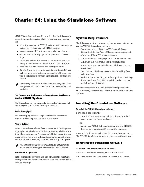
Chapter 24: Using the Standalone SoftwareVENUE Standalone software lets you do all of the following to preconfigure performances, wherever you can use your lap-top:•Learn the basics of the VENUE software interface in prep-aration for working at a full VENUE system. •Assign hardware I/O and routing, and name channels.•Set channel input, EQ, dynamics, pan, and other set-tings. •Create and maintain a library of setups, with access to nearly all parameters available on the control surface. •Store and recall Snapshots, and configure Events.•Use the Filing features to transfer Shows, Shows Folders, and plug-in presets to/from a compatible USB storage de-vice to transfer data between the standalone software and VENUE.Differences Between Standalone Software and a VENUE SystemThe Standalone software is nearly identical to that on a full VENUE system, with the following differences:Audio ThroughputYou cannot play audio through the Standalone software. Real-time audio requires the VENUE hardware.Plug-In EditingWhen a Show is transferred from a complete VENUE system, all plug-ins installed on the D-Show system are visible in the Standalone software as offline (unavailable) plug-ins. You can assign offline plug-ins to racks, and assign plug-in rack routing in the Standalone software, and save the routing in snapshots.Hardware ConfigurationIn the Standalone software, you can simulate the hardware configuration of a destination system from the Devices tab of the Options page.System RequirementsThe following are the minimum system requirements for us-ing the VENUE Standalone software:•Computer running Windows XP Pro or XP HomeEdition O/S, Service Pack 1 (Macintosh not supported)•Minimum 1024 x 768 screen resolution•Minimum 16-bit color graphics, 32-bit recommended •Minimum 256 MB RAM, 512 MB recommended •Minimum 200 MB of available hard disk space, 512 MB recommended •CD-ROM drive for installation (unless installing from web-download)•Available USB 1.1 or 2.0 port and compatible USB storage device (such as a flash disk, key disk or other external hard drive) for file transfer Installation requires Windows Administrator permissions. Once installed, the software can be run under Admin or User accounts.Installing the Standalone SoftwareTo install the VENUE Standalone software:1 Do one of the following:•Download the VENUE Standalone Software Installer from the website ().– or –•Insert your VENUE Software Installer into the CD-ROM drive on your Windows XP-compatible computer.2 Launch the installer and follow the instructions on-screen.The VENUE Standalone software requires no authorization.Removing the Standalone SoftwareTo remove the VENUE Standalone software:1 Launch the Add/Remove Programs Control Panel.2 Choose VENUE , then follow the instructions on-screen.Transferring data must be done to/from a compatible USB storage device such as a USB key disk or other external USB hard drive.You cannot install plug-ins or adjust plug-in parametersunless you are working on the complete VENUE system.Simulating a VENUE ConfigurationYou can use the Standalone software to simulate a VENUE sys-tem with any number of input and outputs. The correspond-ing inputs and outputs become available in the Patchbay, al-lowing you to prepare a show that can transfer directly to the destination system.To simulate a VENUE system:1 Launch the Standalone software.2 Go to the Options page and click the Devices tab.3 Right-click the console graphic and choose the type of con-sole you will be working with.4 Right-click an I/O graphic and choose the type of I/O (as available) and specify the number of Input and Output cards on the destination system.Transfer and Filing Quick StartThe basic steps for using the Standalone software and data transfer are as follows:•Save data to disk, then transfer it to an external USB storage device.•Transfer data from the USB device, then load the data. Save and Transfer Data from aVENUE SystemTo save and transfer data from the complete system:1 Connect a USB storage device to a VENUE USB port.2 Use the Save tab of the Filing page to save VENUE data to disk.3 Go to the Filing page and click the Transfer tab.4 Do one of the following to select the type of data to transfer:•To transfer all data, click the Console icon.•To transfer Console Settings, click the Settings icon.•To transfer Show Folders, click the Show Folders icon.•To transfer individual Shows, click the Shows icon.•To transfer Preset Folders, click the Preset Folders i con.•To transfer Presets for individual items, click the Built-In icon or the Plug-In i con and choose a processor, plug-in or Input Channel Presets item from the pop-up menu, orclick the Scope Sets icon.5 In the left column, select the items you want to transfer from VENUE to the portable storage device.6 Click the Transfer button.Adding Stage Rack inputs and outputsFor complete instructions on transferring data, see Chapter20, “Shows and File Management.”Transferring Show files from VENUETransfer and Load Data to theStandalone Software1 Connect the USB storage device to your laptop. Make sure the drive is mounted before proceeding.2 Launch the VENUE standalone software.3 Go to the Filing page and click the Transfer tab.4 Make sure your USB disk is available in the list at right.5 Click the Console, Settings, Show Folders, Shows, Preset Fold-ers, Built-In, Plug-In or Scope Set selectors to select the type of data you want to transfer.6 Click the Transfer button. The data is transferred from the USB device to the appropriate VENUE data folders on the lap-top.7 If you chose Console, data is automatically loaded and ap-plied. If you chose any other data type, go to the Filing page and click the Load tab, and load the newly transferred data into the Standalone software.Creating and Editing Shows and PresetsUse the techniques explained throughout this guide to assign routing, rename channels, and to configure other parameters. Then do the following to save and transfer your work to a complete system.To save and transfer VENUE data from the standalone software to the complete system:1 Connect a USB storage device to an available USB port on your laptop.2 Using the Save tab of the Filing page, save data to disk.3 Go to the Filing page and click the Transfer tab, and transfer saved data to a compatible USB storage device.4 Connect the USB storage device to an available USB port on the complete system.5 Use the Transfer tab of the Filing page to transfer the VENUE data from the USB storage device.6 Use the Load tab of the Filing page to load the transferred data.CD TransferThe VENUE system provides a CD-ROM drive that can also be used as a source device for VENUE data transfer. (You cannot write data to the FOH Rack CD-ROM drive; it is read-only.)To use a CD for transfer:1 Using the Standalone software on a laptop or other com-puter, create and save a show.2 Locate the VENUE data folder on the system drive.3 Copy that folder and its contents to a CD-ROM. Make sure the folder is at the root level of the CD-ROM.4 Burn or write the disc as a Windows-compatible CD-ROM.5 Insert the CD-ROM into a VENUE CD-ROM drive.6 In the Filing screen, select the CD-ROM drive as the source for file transfer.7 When the transfer is complete, eject the CD-ROM.Transferring a Scope Set for the standalone softwareClickLeaving a disc in the CD-ROM drive of a VENUE systemcan slow down the response of some software screens, so itis recommended that you not leave any disc in the drive dur-ing a performance. This only applies to a VENUE CD-ROMdrive (not the laptop on which you’re running the stand-alone software).Exporting System Information and Patchbay InformationWith Standalone software, a complete system description and/or the contents of each Patchbay page can be exported to a text file. These can be useful for generating an input list (line list) directly from the system. For example, build and custom-ize the Patchbay for an upcoming show, then export and print the channel names list for use during sound check. To print a system description:1 Go to the Options > System tab.2 Click the Info button and follow the on-screen instructionsto print a complete system description.For more information, see “VENUE System Information Ex-port” on page 110. To export Patchbay names:1 Go to the Patchbay page you want to export.2 Click the Export Patch List icon in the upper right corner ofthe screen.The Patchbay names appear in an open HTML file that you can save and print, or open in an HTML-compatible applica-tion for formatting or other modification. For more informa-tion, see “Patch List Export” on page 111.Export Patch List buttonClick to export as HTML。
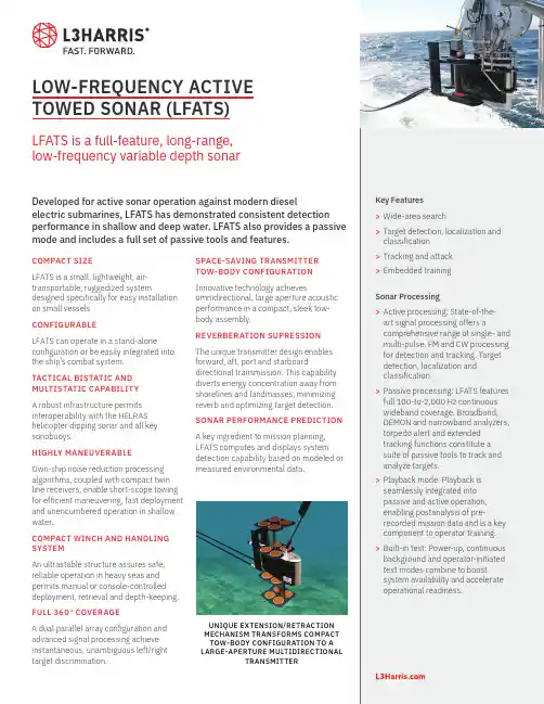
LOW-FREQUENCY ACTIVE TOWED SONAR (LFATS)LFATS is a full-feature, long-range,low-frequency variable depth sonarDeveloped for active sonar operation against modern dieselelectric submarines, LFATS has demonstrated consistent detection performance in shallow and deep water. LFATS also provides a passive mode and includes a full set of passive tools and features.COMPACT SIZELFATS is a small, lightweight, air-transportable, ruggedized system designed specifically for easy installation on small vessels. CONFIGURABLELFATS can operate in a stand-alone configuration or be easily integrated into the ship’s combat system.TACTICAL BISTATIC AND MULTISTATIC CAPABILITYA robust infrastructure permits interoperability with the HELRAS helicopter dipping sonar and all key sonobuoys.HIGHLY MANEUVERABLEOwn-ship noise reduction processing algorithms, coupled with compact twin line receivers, enable short-scope towing for efficient maneuvering, fast deployment and unencumbered operation in shallow water.COMPACT WINCH AND HANDLING SYSTEMAn ultrastable structure assures safe, reliable operation in heavy seas and permits manual or console-controlled deployment, retrieval and depth-keeping. FULL 360° COVERAGEA dual parallel array configuration and advanced signal processing achieve instantaneous, unambiguous left/right target discrimination.SPACE-SAVING TRANSMITTERTOW-BODY CONFIGURATIONInnovative technology achievesomnidirectional, large aperture acousticperformance in a compact, sleek tow-body assembly.REVERBERATION SUPRESSIONThe unique transmitter design enablesforward, aft, port and starboarddirectional transmission. This capabilitydiverts energy concentration away fromshorelines and landmasses, minimizingreverb and optimizing target detection.SONAR PERFORMANCE PREDICTIONA key ingredient to mission planning,LFATS computes and displays systemdetection capability based on modeled ormeasured environmental data.Key Features>Wide-area search>Target detection, localization andclassification>T racking and attack>Embedded trainingSonar Processing>Active processing: State-of-the-art signal processing offers acomprehensive range of single- andmulti-pulse, FM and CW processingfor detection and tracking. Targetdetection, localization andclassification>P assive processing: LFATS featuresfull 100-to-2,000 Hz continuouswideband coverage. Broadband,DEMON and narrowband analyzers,torpedo alert and extendedtracking functions constitute asuite of passive tools to track andanalyze targets.>Playback mode: Playback isseamlessly integrated intopassive and active operation,enabling postanalysis of pre-recorded mission data and is a keycomponent to operator training.>Built-in test: Power-up, continuousbackground and operator-initiatedtest modes combine to boostsystem availability and accelerateoperational readiness.UNIQUE EXTENSION/RETRACTIONMECHANISM TRANSFORMS COMPACTTOW-BODY CONFIGURATION TO ALARGE-APERTURE MULTIDIRECTIONALTRANSMITTERDISPLAYS AND OPERATOR INTERFACES>State-of-the-art workstation-based operator machineinterface: Trackball, point-and-click control, pull-down menu function and parameter selection allows easy access to key information. >Displays: A strategic balance of multifunction displays,built on a modern OpenGL framework, offer flexible search, classification and geographic formats. Ground-stabilized, high-resolution color monitors capture details in the real-time processed sonar data. > B uilt-in operator aids: To simplify operation, LFATS provides recommended mode/parameter settings, automated range-of-day estimation and data history recall. >COTS hardware: LFATS incorporates a modular, expandable open architecture to accommodate future technology.L3Harrissellsht_LFATS© 2022 L3Harris Technologies, Inc. | 09/2022NON-EXPORT CONTROLLED - These item(s)/data have been reviewed in accordance with the InternationalTraffic in Arms Regulations (ITAR), 22 CFR part 120.33, and the Export Administration Regulations (EAR), 15 CFR 734(3)(b)(3), and may be released without export restrictions.L3Harris Technologies is an agile global aerospace and defense technology innovator, delivering end-to-endsolutions that meet customers’ mission-critical needs. The company provides advanced defense and commercial technologies across air, land, sea, space and cyber domains.t 818 367 0111 | f 818 364 2491 *******************WINCH AND HANDLINGSYSTEMSHIP ELECTRONICSTOWED SUBSYSTEMSONAR OPERATORCONSOLETRANSMIT POWERAMPLIFIER 1025 W. NASA Boulevard Melbourne, FL 32919SPECIFICATIONSOperating Modes Active, passive, test, playback, multi-staticSource Level 219 dB Omnidirectional, 222 dB Sector Steered Projector Elements 16 in 4 stavesTransmission Omnidirectional or by sector Operating Depth 15-to-300 m Survival Speed 30 knotsSize Winch & Handling Subsystem:180 in. x 138 in. x 84 in.(4.5 m x 3.5 m x 2.2 m)Sonar Operator Console:60 in. x 26 in. x 68 in.(1.52 m x 0.66 m x 1.73 m)Transmit Power Amplifier:42 in. x 28 in. x 68 in.(1.07 m x 0.71 m x 1.73 m)Weight Winch & Handling: 3,954 kg (8,717 lb.)Towed Subsystem: 678 kg (1,495 lb.)Ship Electronics: 928 kg (2,045 lb.)Platforms Frigates, corvettes, small patrol boats Receive ArrayConfiguration: Twin-lineNumber of channels: 48 per lineLength: 26.5 m (86.9 ft.)Array directivity: >18 dB @ 1,380 HzLFATS PROCESSINGActiveActive Band 1,200-to-1,00 HzProcessing CW, FM, wavetrain, multi-pulse matched filtering Pulse Lengths Range-dependent, .039 to 10 sec. max.FM Bandwidth 50, 100 and 300 HzTracking 20 auto and operator-initiated Displays PPI, bearing range, Doppler range, FM A-scan, geographic overlayRange Scale5, 10, 20, 40, and 80 kyd PassivePassive Band Continuous 100-to-2,000 HzProcessing Broadband, narrowband, ALI, DEMON and tracking Displays BTR, BFI, NALI, DEMON and LOFAR Tracking 20 auto and operator-initiatedCommonOwn-ship noise reduction, doppler nullification, directional audio。
failed to read simulation model from fields“Failed to read simulation model from fields”可能是由多种因素导致的,包括但不限于以下内容:1. 模型文件损坏或缺失:当模型文件被误删除、病毒攻击或存储介质损坏时,可能会导致“Failed to read simulation modelfrom fields”的错误出现。
此时,通常需要重新下载或获取模型文件。
2. 内存不足:当计算机内存不足时,会出现“Failed to read simulation model from fields”错误。
此时,可能需要关闭其他程序或升级计算机硬件。
3. 软件版本不兼容:当使用不兼容的软件版本时,可能会出现“Failed to read simulation model from fields”的错误。
此时,通常需要更新软件到最新版本。
4. 安装文件错误:如果在安装软件时发生错误,可能会导致“Failed to read simulation model from fields”错误的出现。
此时,可能需要重新安装软件,或者采用其他安装方式。
解决“Failed to read simulation model from fields”错误的方法如下:1. 检查模型文件是否完好无损,如果不行则下载或获取新的模型文件。
2. 检查计算机内存是否足够,如果不足则关闭其他程序或升级硬件。
3. 检查软件版本是否最新,如果没有则更新软件。
4. 如果安装软件时出现问题,则尝试重新安装软件或采用其他安装方式。
总之,“Failed to read simulation model from fields”错误的出现可能会影响计算机模拟的精度和准确性,因此需要及时的解决。
对于不同的情况,采取不同的解决方法是非常必要的。
通过以上几种方案,很多用户都能轻松的消除这个错误,并且提高自己的工作效率。
Goanna—A Static Model Checker Ansgar Fehnker1,Ralf Huuck1,Patrick Jayet2 ,Michel Lussenburg2∗,andFelix Rauch11National ICT Australia Ltd.(NICTA) and University of New South Wales,Locked Bag6016,NSW1466,Australia2Department of Computer Science,Swiss Federal Institute of Technology(ETH),CH-8092Zurich,SwitzerlandAbstract.In this work we present Goanna,thefirst tool that uses anoff-the-shelf model checker for the static analysis of C/C++source code.We outline its architecture and show how syntactic properties can be ex-pressed in CTL.Once the properties have been defined the tool analysessource code automatically and efficiently.We demonstrate its applica-bility by presenting experimental results on analysing OpenSSL and theGNU coreutils.1IntroductionFormal design and analysis techniques are successfully applied to hardware.In fact,model checking parts of the chip design is common practice.However,the application of verification technology to existing and complex software has been much less successful.The reasons are manifold:Full formal verification as done by interactive the-orem proving is expensive.It requires a lot of time and expertise,making it often impractical for software that has a short life cycle,is not highly safety-critical,or suffers from a high pressure to market.Algorithmic verification techniques have to deal with software’s infinite state space,requiring abstraction techniques to make properties of interest decidable.Suitable abstractions are typically hard to compute and the overall interaction required by the user in order to apply them to real-life software are often considerable.One area that has been successful is static analysis[1,2].Approaches such as abstract interpretation,dataflow analysis and other static checking techniques have made it into several industrial strength tools.In this work we present Goanna[3],a static analysis tool for C/C++source code based on model checking.It uses the NuSMV[4]model checker as the underlying verification engine,allows the specification of user defined properties This work was carried out while visiting NICTA.National ICT Australia is funded by the Australian Governments Department of Communications,Information Technology and the Arts and the Australian Research Council through Backing Australias Ability and the ICT Research Centre of Excel-lence programs.and scales well to commercial size software.Since Goanna does not require any user interaction it makes it particularly suited to be integrated into the software development process.Moreover,it is thefirst step of bringing static analysis and software model checking closer together by providing one uniform framework. 2TechnologyThe basic ideas of solving static analysis problems by model checking have been first developed by Steffen and Schmidt[5].While their main focus has been on developing a safe approximation of the program’s behaviour to check for safety properties,we abandon in some cases the soundness of the analysis for effectiveness.This means we can check for full CTL including(syntactic)liveness properties.The CTL model checking problem is encoded in two steps and we illustrate this by a simple example.First we define the atomic propositions of interest we like to reason about,e.g.,whether a variable is declared,used,or assigned a value. For a variable named x we write decl x,used x and assigned x for the respective propositions.We use a pattern matching approach to relate certain patterns on a program’s abstract syntax tree(AST)with propositions of interest.In a second step we automatically extract the controlflow graph(CFG)of a program and label it with the previously determined propositions.Fig.1.Goanna architecture Fig.2.Goanna results in EclipseThe translation of an annotated CFG into a NuSMV model is rather straight-forward and the encoding can be done in an efficient way resulting in a small state space.Properties of interest can then be expressed as CTL formulae over this model.E.g.,checking for uninitialised variables can be expressed as follows:AG decl x⇒(A¬used x W assigned x)This means we require that on all program paths if a variable is declared it must not be used until it has a value assigned or it will not be used at all.Weuse the weak until operator W here to include the second possibility.The latter can also point to unused variables,which is checked separately.Our tool chain is depicted in Figure1.We use gcc as a front end,as one of its features allows us to easily output the AST of C/C++programs in an intermediate language.We parse the AST and on the one hand generate the CFG from it and on the other hand match patterns on the AST,which constitute the atomic propositions of a CTL formula expressing the desired property.We label the CFG with atomic propositions where their respective patterns were matched. Once the patterns and the CTL formula have been specified,the translation of the C/C++source code into a suitable NuSMV model and its checking is fully automatic.The current implementation is developed in OCaml.Goanna is easily inte-grated in Makefiles and,thus,is automatically supported by development envi-ronments such as Eclipse.A screen shot of Goanna running in combination with Eclipse can be found in Figure2.As a result we obtain a seamless integration into the overall software development process.3ApplicationTo evaluate the applicability of our tool,we examine two real-world open-source software packages:The GNU coreutils3,which provide basicfile,shell and text manipulation utilities(59kLoC4),and the OpenSSL5toolkit imple-menting the Secure Sockets Layer(SSL)and Transport Layer Security(TLS) protocols(260kLoC).We analyse the source code of these two packages on a recent3.4GHz Xeon-processor-based server.Analysing the whole source with our current Goanna tool(which has not yet been optimised)takes slightly less than2minutes for the coreutils and slightly less than29minutes for OpenSSL.The latter is somewhat distorted by a single pathologicalfile that takes almost12minutes to analyse.In practice,analysis times are typically much shorter,because the analysis can be done incrementally on the set of recently changedfiles only and a more in-depth study of Goanna’s analysis times shows that a large majority of sourcefiles is analysed quite quickly. In fact,72%of all sourcefiles in the coreutils are analysed in less than1second and95%under5seconds.Similarly,for OpenSSL83%of allfiles are analysed in under1second and again95%under5seconds.Note that the current prototype has not yet been optimised regarding exe-cution time.Hence,there is still a lot of room for performance improvements, for example by optimising the search in the AST for patterns of interest(which currently contains redundant searches for different properties),the OCaml li-brary we use to conduct the search on the AST(which is convenient to use but not efficient),or by changing the way in which we use NuSMV(which is cur-3/software/coreutils/4LoC=Lines of Code,kLoC=1000Lines of Codes5/rently invoked with rather large chunks of source code at the time that could be reduced to smaller pieces).Looking at the memory requirements of our tool wefind that the maximum memory consumption of the analysis is about65MiB to analyse the coreutils and about113MiB for OpenSSL respectively.This is in both cases much below the limit set by todays PCs used by developers.The above numbers show that the tool is already quite usable in practice.A full evaluation of course requires also an analysis of the precision of the tool, with looking at the number of real bugs found and the number of false positives reported.Such a study is very time consuming and we are still in the process of qualitatively evaluating Goanna regarding its precision.Preliminary results indicate that the precision of our approach is comparable to standard static analysis.4ConclusionIn this work we presented Goanna,thefirst static analyser purely based on an off-the-shelf model checker.We demonstrated that the approach scales well to real-life software,making it suitable for the integration into the overall software development process.While Goanna is fast,it is not yet more precise than traditional static analy-sis.However,we anticipate to improve on this by incorporating more semantic-based software model checking techniques such as predicate abstraction[6].The foundation of this integration has been laid by having a uniform framework for static analysis as well as traditional model checking.References1.Engler,D.R.,Musuvathi,M.:Static analysis versus software model checking forbugfinding.In:”VMCAI’04:5th Intl.Conference Verification,Model Checking and Abstract Interpretation”.(2004)191–2102.Blanchet,B.,Cousot,P.,Cousot,R.,Feret,J.,Mauborgne,L.,Min´e;,A.,Monni-aux,D.,Rival,X.:Design and implementation of a special-purpose static program analyzer for safety-critical real-time embedded software.(2002)85–1083.NICTA:The Goanna Project.(.au/research/goanna/)4.Cimatti,A.,Clarke,E.,Giunchiglia,E.,Giunchiglia,F.,Pistore,M.,Roveri,M.,Sebastiani,R.,Tacchella,A.:NuSMV Version2:An OpenSource Tool for Symbolic Model Checking.In:Proc.International Conference on Computer-Aided Verification (CAV2002).Volume2404of LNCS.,Springer(2002)5.Schmidt,D.A.,Steffen,B.:Program analysis as model checking of abstract inter-pretations.In:SAS’98:Proceedings of the5th International Symposium on Static Analysis,London,UK,Springer-Verlag(1998)351–3806.Ball,T.,Cook,B.,Levin,V.,Rajamani,S.K.:SLAM and Static Driver Verifier:Technology transfer of formal methods inside Microsoft.In:IFM2004:4th Interna-tional Conference on Integrated Formal Methods.Volume2999of LNCS.,Springer-Verlag(2004)1–20Below is given annual work summary, do not need friends can download after editor deleted Welcome to visit againXXXX annual work summaryDear every leader, colleagues:Look back end of XXXX, XXXX years of work, have the joy of success in your work, have a collaboration with colleagues, working hard, also have disappointed when encountered difficulties and setbacks. Imperceptible in tense and orderly to be over a year, a year, under the loving care and guidance of the leadership of the company, under the support and help of colleagues, through their own efforts, various aspects have made certain progress, better to complete the job. For better work, sum up experience and lessons, will now work a brief summary.To continuously strengthen learning, improve their comprehensive quality. With good comprehensive quality is the precondition of completes the labor of duty and conditions. A year always put learning in the important position, trying to improve their comprehensive quality. Continuous learning professional skills, learn from surrounding colleagues with rich work experience, equip themselves with knowledge, the expanded aspect of knowledge, efforts to improve their comprehensive quality.The second Do best, strictly perform their responsibilities. Set up the company, to maximize the customer to the satisfaction of the company's products, do a good job in technical services and product promotion to the company. And collected on the properties of the products of the company, in order to make improvement in time, make the products better meet the using demand of the scene.Three to learn to be good at communication, coordinating assistance. On‐site technical service personnel should not only have strong professional technology, should also have good communication ability, a lot of a product due to improper operation to appear problem, but often not customers reflect the quality of no, so this time we need to find out the crux, and customer communication, standardized operation, to avoid customer's mistrust of the products and even the damage of the company's image. Some experiences in the past work, mentality is very important in the work, work to have passion, keep the smile of sunshine, can close the distance between people, easy to communicate with the customer. Do better in the daily work to communicate with customers and achieve customer satisfaction, excellent technical service every time, on behalf of the customer on our products much a understanding and trust.Fourth, we need to continue to learn professional knowledge, do practical grasp skilled operation. Over the past year, through continuous learning and fumble, studied the gas generation, collection and methods, gradually familiar with and master the company introduced the working principle, operation method of gas machine. With the help of the department leaders and colleagues, familiar with and master the launch of the division principle, debugging method of the control system, and to wuhan Chen Guchong garbage power plant of gas machine control system transformation, learn to debug, accumulated some experience. All in all, over the past year, did some work, have also made some achievements, but the results can only represent the past, there are some problems to work, can't meet the higher requirements. In the future work, I must develop the oneself advantage, lack of correct, foster strengths and circumvent weaknesses, for greater achievements. Looking forward to XXXX years of work, I'll be more efforts, constant progress in their jobs, make greater achievements. Every year I have progress, the growth of believe will get greater returns, I will my biggest contribution to the development of the company, believe inyourself do better next year!I wish you all work study progress in the year to come.。
verifying signed artifacts报错的解决方法-回复Verifying Signed Artifacts: A Step-by-Step Troubleshooting GuideIntroduction:In this article, we will explore the common issues and troubleshooting steps associated with the "verifying signed artifacts" error. Verifying signed artifacts is a crucial process in software development and deployment, ensuring that the digital signature attached to a file or artifact is valid and has not been tampered with. However, sometimes these verifications may fail, leading to errors or unexpected behavior. In this comprehensive guide, we will delve into the potential causes of these errors and outline step-by-step solutions to rectify them.Step 1: Understand the BasicsBefore diving into troubleshooting, it is important to have a clear understanding of the concept of signed artifacts and why verification is essential. Signed artifacts are files that have a digital signature attached to them, intended to prove the authenticity and integrity of the file. The verification process involves checking the signature against a trusted certificate authority (CA) to ensure its validity.Step 2: Identify the Error MessageThe first step in troubleshooting is to identify the exact error message you encounter when trying to verify the signed artifact. This information is crucial as it provides important clues about the root cause of the problem. Common error messages may indicate issues with the certificate, the signing process, or the verification mechanism.Step 3: Check the Certificate ChainOne possible cause of the error is an incomplete or improperly installed certificate chain. Start by checking the certificate chain attached to the signed artifact. Ensure that all intermediate certificates are present and correctly installed on the machine doing the verification. If any of the certificates are missing or expired, obtain the correct certificates from the issuing CA and install them correctly.Step 4: Verify the Certificate Revocation StatusAnother potential issue could be the revocation status of the certificate used to sign the artifact. Certificates can be revoked for various reasons, including compromise, expiration, or a change inthe certificate owner's circumstances. Verify the revocation status of the certificate using the certificate's serial number or thumbprint. Check the certificate authority's Certificate Revocation List (CRL) or Online Certificate Status Protocol (OCSP) to ensure that the certificate is valid and has not been revoked.Step 5: Validate the Digital Signature AlgorithmSometimes, the error can be caused by an incompatibility between the signing algorithm used to sign the artifact and the verification mechanism being used to validate it. Ensure that the signature algorithm used is supported by the verification process. Check if the verification mechanism requires specific algorithms or cryptographic standards, and verify that the signature algorithm used is compliant.Step 6: Confirm the Trustworthiness of the CertificateThe error could also occur if the certificate used to sign the artifact is not trusted by the verification mechanism. Check the trust anchors, root certificates, or certificate trust lists (CTLs) used by the verification component. Ensure that the certificate used to sign the artifact is present and trusted.Step 7: Verify Time and Date SettingsIncorrect time and date settings on the machine performing the verification can also cause errors during the verification process. Ensure that the system clock is correctly set and synchronized with a reliable time source. An incorrect time or date can cause the verification mechanism to deem the certificate invalid.Step 8: Update Software and Security ComponentsOutdated or incompatible software or security components can introduce compatibility issues that lead to verification errors. Ensure that all relevant software, including certificate authorities, verification libraries, and operating systems, are up to date. Check with the software vendors for any known issues or updates specific to the verification process.Step 9: Seek Assistance from Trusted SourcesIf the above steps do not resolve the issue, it might be beneficial to seek assistance from trusted sources. Reach out to software vendors, certificate authorities, or online forums dedicated to software security and digital signatures. These sources may provide specific guidance or solutions tailored to your particular situation.Conclusion:Verifying signed artifacts is a critical step in ensuring the integrity and authenticity of software. This troubleshooting guide has provided a step-by-step approach to identify and resolve the "verifying signed artifacts" error. By understanding the basics, checking the certificate chain, validating the signing algorithm, and confirming trustworthiness, you can diagnose and rectify common issues that may arise during the verification process. Remember to keep all software up to date and seek assistance when needed. With these steps, you can ensure the successful verification of signed artifacts and maintain the security and trustworthiness of your software.。

cycledetectinglockfactory用法-概述说明以及解释1.引言1.1 概述在多线程编程中,控制线程之间的并发访问是至关重要的。
为了避免死锁和其他并发访问问题,我们需要使用适当的锁机制来确保线程安全。
cycledetectinglockfactory是一个用于检测和防止死锁的工厂类,它提供了一种先进的锁机制。
通过cycledetectinglockfactory,我们可以轻松创建具有循环检测功能的锁对象,以避免因线程之间互相持有锁而导致的死锁情况。
这种锁机制可以有效减少程序中出现的并发访问问题,提高程序的稳定性和性能。
本文将介绍cycledetectinglockfactory的简介、使用方法和优势,帮助读者更好地理解并正确应用这一先进的锁机制。
1.2 文章结构本文将首先介绍cycledetectinglockfactory的概念和背景,包括其作用和原理。
接着将详细讲解cycledetectinglockfactory的使用方法,包括如何初始化和调用该工厂类来创建锁。
然后将探讨cycledetectinglockfactory相比于传统锁的优势和特点,以及在实际应用中的应用场景和效果。
最后,通过总结cycledetectinglockfactory的应用,展望未来cycledetectinglockfactory的发展方向,并给出作者的一些思考和建议。
通过以上结构,读者将能够全面了解和掌握cycledetectinglockfactory的用法和作用,进而可以更好地应用和推广该工具。
1.3 目的本文的目的是介绍cycledetectinglockfactory的用法,帮助读者了解如何有效地利用该工具来管理锁以避免死锁和循环依赖的问题。
通过对cycledetectinglockfactory的简介、使用方法和优势进行全面介绍,使读者能够更好地理解该工具的价值和作用,从而在实际开发中更加灵活和高效地运用它。
ap autosar中的坑英语1. Pitfall -安全问题2. Misconfiguration -配置错误3. Incompatibility -不兼容4. Ambiguity -歧义5. Overlapping -重叠6. Deadlock -死锁7. Race condition -竞争条件8. Memory leak -内存泄漏9. Stack overflow -栈溢出10. Infinite loop -无限循环11. Null pointer exception -空指针异常12. Data corruption -数据损坏13. Timing issue -时序问题14. Kernel panic -内核崩溃15. Resource exhaustion -资源耗尽16. Non-deterministic behavior -非确定性行为17. Bus contention -总线冲突18. Buffer overflow -缓冲区溢出19. Denial of Service (DoS) -拒绝服务攻击20. Input validation -输入验证21. Code injection -代码注入22. Side channel attack -侧信道攻击23. Backdoor -后门24. Man-in-the-middle attack -中间人攻击25. Security vulnerability -安全漏洞1. The system encountered a pitfall due to a software bug.系统由于软件漏洞而遭遇到一个安全问题。
2. The misconfiguration of network settings resulted in a communication failure.网络设置的配置错误导致了通讯故障。
3. The new software version is incompatible with the previous hardware version.新软件版本与之前的硬件版本不兼容。
fr-iqa 设计原则
FRIQA是一种软件设计原则,它代表的是:
F - 封闭原则(The Closed Principle):软件中的类应该对扩展开放,对修改关闭。
这意味着应该通过添加新的代码来扩展功能,而不是修改现有的代码。
R - 重用原则(The Reuse Principle):软件中的可重用性应该是优先考虑的。
通过将代码组织为可重用的模块、组件或类,可以提高代码的复用度,减少重复编写相似功能的代码。
I - 接口分离原则(The Interface Segregation Principle):应该根据使用的客户端的需求来划分接口,而不是设计一个庞大臃肿的接口。
通过保持接口的粒度小和单一职责原则,可以使系统更易于维护和扩展。
Q - 依赖倒置原则(The Dependency Inversion Principle):高层模块不应该依赖低层模块,两者都应该依赖于抽象。
这种原则强调了面向接口编程的重要性,通过使用依赖注入等技术,可以降低类之间的耦合度。
A - 好处(Advantage):遵循FRIQA原则可以提高软件的可维护性、可扩展性和可重用性,使代码更加灵活和易于测试。
因此,在软件设计中遵循FRIQA原则可以帮助开发人员构建高质量的软件系统。