模具 外文翻译 外文文献 注塑模
- 格式:doc
- 大小:1.12 MB
- 文档页数:17
外文翻译及原文(文档含英文原文和中文翻译)【原文一】CONCURRENT DESIGN OF PLASTICS INJECTION MOULDS AbstractThe plastic product manufacturing industry has been growing rapidly in recent years. One of the most popular processes for making plastic parts is injection moulding. The design of injection mould is critically important to product quality and efficient product processing.Mould-making companies, who wish to maintain the competitive edge, desire to shorten both design and manufacturing leading times of the by applying a systematic mould design process. The mould industry is an important support industry during the product development process, serving as an important link between the product designer and manufacturer. Product development has changed from the traditional serial process of design, followed by manufacture, to a more organized concurrent process where design and manufacture are considered at a very early stage of design. The concept of concurrent engineering (CE) is no longer new and yet it is still applicable and relevant in today’s manuf acturing environment. Team working spirit, management involvement, total design process and integration of IT tools are still the essence of CE. The application of The CE process to the design of an injection process involves the simultaneous consideration of plastic part design, mould design and injection moulding machine selection, production scheduling and cost as early as possible in the design stage.This paper presents the basic structure of an injection mould design. The basis of this system arises from an analysis of the injection mould design process for mould design companies. This injection mould design system covers both the mould design process and mould knowledge management. Finally the principle of concurrent engineering process is outlined and then its principle is applied to the design of a plastic injection mould.Keywords :Plastic injection mould design, Concurrent engineering, Computer aided engineering, Moulding conditions, Plastic injection moulding, Flow simulation1.IntroductionInjection moulds are always expensive to make, unfortunately without a mould it can not be possible ho have a moulded product. Every mould maker has his/her own approach to design a mould and there are many different ways of designing and building a mould. Surely one of the most critical parameters to be considered in the design stage of the mould is the number of cavities, methods of injection, types of runners, methods of gating, methods of ejection, capacity and features of the injection moulding machines. Mould cost, mould quality and cost of mould product are inseparableIn today’s completive environment, computer aided mould filling simulation packages can accurately predict the fill patterns of any part. This allows for quick simulations of gate placements and helps finding the optimal location. Engineers can perform moulding trials on the computer before the part design is completed. Process engineers can systematically predict a design and process window, and can obtain information about the cumulative effect of the process variables that influence part performance, cost, and appearance.2.Injection MouldingInjection moulding is one of the most effective ways to bring out the best in plastics. It is universally used to make complex, finished parts, often in a single step, economically, precisely and with little waste. Mass production of plastic parts mostly utilizes moulds. The manufacturing process and involving moulds must be designed after passing through the appearance evaluation and the structure optimization of the product design. Designers face a hugenumber of options when they create injection-moulded components. Concurrent engineering requires an engineer to consider the manufacturing process of the designed product in the development phase. A good design of the product is unable to go to the market if its manufacturing process is impossible or too expensive. Integration of process simulation, rapid prototyping and manufacturing can reduce the risk associated with moving from CAD to CAM and further enhance the validity of the product development.3. Importance of Computer Aided Injection Mould DesignThe injection moulding design task can be highly complex. Computer Aided Engineering (CAE) analysis tools provide enormous advantages of enabling design engineers to consider virtually and part, mould and injection parameters without the real use of any manufacturing and time. The possibility of trying alternative designs or concepts on the computer screen gives the engineers the opportunity to eliminate potential problems before beginning the real production. Moreover, in virtual environment, designers can quickly and easily asses the sensitivity of specific moulding parameters on the quality and manufacturability of the final product. All theseCAE tools enable all these analysis to be completed in a meter of days or even hours, rather than weeks or months needed for the real experimental trial and error cycles. As CAE is used in the early design of part, mould and moulding parameters, the cost savings are substantial not only because of best functioning part and time savings but also the shortens the time needed to launch the product to the market.The need to meet set tolerances of plastic part ties in to all aspects of the moulding process, including part size and shape, resin chemical structure, the fillers used, mould cavity layout, gating, mould cooling and the release mechanisms used. Given this complexity, designers often use computer design tools, such as finite element analysis (FEA) and mould filling analysis (MFA), to reduce development time and cost. FEA determines strain, stress and deflection in a part by dividing the structure into small elements where these parameters can be well defined. MFA evaluates gate position and size to optimize resin flow. It also defines placement of weld lines, areas of excessive stress, and how wall and rib thickness affect flow. Other finite element design tools include mould cooling analysis for temperature distribution, and cycle time and shrinkage analysis for dimensional control and prediction of frozen stress and warpage.The CAE analysis of compression moulded parts is shown in Figure 1. The analysis cycle starts with the creation of a CAD model and a finite element mesh of the mould cavity. After the injection conditions are specified, mould filling, fiber orientation, curing and thermal history, shrinkage and warpage can be simulated. The material properties calculated by the simulation can be used to model the structural behaviour of the part. If required, part design, gate location and processing conditions can be modified in the computer until an acceptable part is obtained. After the analysis is finished an optimized part can be produced with reduced weldline (known also knitline), optimized strength, controlled temperatures and curing, minimized shrinkage and warpage.Machining of the moulds was formerly done manually, with a toolmaker checking each cut. This process became more automated with the growth and widespread use of computer numerically controlled or CNC machining centres. Setup time has also been significantly reduced through the use of special software capable of generating cutter paths directly from a CAD data file. Spindle speeds as high as 100,000 rpm provide further advances in high speed machining. Cutting materials have demonstrated phenomenal performance without the use of any cutting/coolant fluid whatsoever. As a result, the process of machining complex cores and cavities has been accelerated. It is good news that the time it takes to generate a mould is constantly being reduced. The bad news, on the other hand, is that even with all these advances, designing and manufacturing of the mould can still take a long time and can be extremely expensive.Figure 1 CAE analysis of injection moulded partsMany company executives now realize how vital it is to deploy new products to market rapidly. New products are the key to corporate prosperity. They drive corporate revenues, market shares, bottom lines and share prices. A company able to launch good quality products with reasonable prices ahead of their competition not only realizes 100% of the market before rival products arrive but also tends to maintain a dominant position for a few years even after competitive products have finally been announced (Smith, 1991). For most products, these two advantages are dramatic. Rapid product development is now a key aspect of competitive success. Figure 2 shows that only 3–7% of the product mix from the average industrial or electronics company is less than 5 years old. For companies in the top quartile, the number increases to 15–25%. For world-class firms, it is 60–80% (Thompson, 1996). The best companies continuously develop new products. AtHewlett-Packard, over 80% of the profits result from products less than 2 years old! (Neel, 1997)Figure 2. Importance of new product (Jacobs, 2000)With the advances in computer technology and artificial intelligence, efforts have been directed to reduce the cost and lead time in the design and manufacture of an injection mould. Injection mould design has been the main area of interest since it is a complex process involving several sub-designs related to various components of the mould, each requiring expert knowledge and experience. Lee et. al. (1997) proposed a systematic methodology and knowledge base for injection mould design in a concurrent engineering environment.4.Concurrent Engineering in Mould DesignConcurrent Engineering (CE) is a systematic approach to integrated product development process. It represents team values of co-operation, trust and sharing in such a manner that decision making is by consensus, involving all per spectives in parallel, from the very beginning of the productlife-cycle (Evans, 1998). Essentially, CE provides a collaborative, co-operative, collective and simultaneous engineering working environment. A concurrent engineering approach is based on five key elements:1. process2. multidisciplinary team3. integrated design model4. facility5. software infrastructureFigure 3 Methodologies in plastic injection mould design, a) Serial engineering b) Concurrent engineeringIn the plastics and mould industry, CE is very important due to the high cost tooling and long lead times. Typically, CE is utilized by manufacturing prototype tooling early in the design phase to analyze and adjust the design. Production tooling is manufactured as the final step. The manufacturing process and involving moulds must be designed after passing through the appearance evaluation and the structure optimization of the product design. CE requires an engineer to consider the manufacturing process of the designed product in the development phase.A good design of the product is unable to go to the market if its manufacturing process is impossible. Integration of process simulation and rapid prototyping and manufacturing can reduce the risk associated with moving from CAD to CAM and further enhance the validity of the product development.For years, designers have been restricted in what they can produce as they generally have todesign for manufacture (DFM) – that is, adjust their design intent to enable the component (or assembly) to be manufactured using a particular process or processes. In addition, if a mould is used to produce an item, there are therefore automatically inherent restrictions to the design imposed at the very beginning. Taking injection moulding as an example, in order to process a component successfully, at a minimum, the following design elements need to be taken into account:1. . geometry;. draft angles,. Non re-entrants shapes,. near constant wall thickness,. complexity,. split line location, and. surface finish,2. material choice;3. rationalisation of components (reducing assemblies);4. cost.In injection moulding, the manufacture of the mould to produce the injection-moulded components is usually the longest part of the product development process. When utilising rapid modelling, the CAD takes the longer time and therefore becomes the bottleneck.The process design and injection moulding of plastics involves rather complicated and time consuming activities including part design, mould design, injection moulding machine selection, production scheduling, tooling and cost estimation. Traditionally all these activities are done by part designers and mould making personnel in a sequential manner after completing injection moulded plastic part design. Obviously these sequential stages could lead to long product development time. However with the implementation of concurrent engineering process in the all parameters effecting product design, mould design, machine selection, production scheduling,tooling and processing cost are considered as early as possible in the design of the plastic part. When used effectively, CAE methods provide enormous cost and time savings for the part design and manufacturing. These tools allow engineers to virtually test how the part will be processed and how it performs during its normal operating life. The material supplier, designer, moulder and manufacturer should apply these tools concurrently early in the design stage of the plastic parts in order to exploit the cost benefit of CAE. CAE makes it possible to replace traditional, sequential decision-making procedures with a concurrent design process, in which all parties can interact and share information, Figure 3. For plastic injection moulding, CAE and related design data provide an integrated environment that facilitates concurrent engineering for the design and manufacture of the part and mould, as well as material selection and simulation of optimal process control parameters.Qualitative expense comparison associated with the part design changes is shown in Figure 4 , showing the fact that when design changes are done at an early stages on the computer screen, the cost associated with is an order of 10.000 times lower than that if the part is in production. These modifications in plastic parts could arise fr om mould modifications, such as gate location, thickness changes, production delays, quality costs, machine setup times, or design change in plastic parts.Figure 4 Cost of design changes during part product development cycle (Rios et.al, 2001)At the early design stage, part designers and moulders have to finalise part design based on their experiences with similar parts. However as the parts become more complex, it gets rather difficult to predict processing and part performance without the use of CAE tools. Thus for even relatively complex parts, the use of CAE tools to prevent the late and expensive design changesand problems that can arise during and after injection. For the successful implementation of concurrent engineering, there must be buy-in from everyone involved.5.Case StudyFigure 5 shows the initial CAD design of plastics part used for the sprinkler irrigation hydrant leg. One of the essential features of the part is that the part has to remain flat after injection; any warping during the injection causes operating problems.Another important feature the plastic part has to have is a high bending stiffness. A number of feeders in different orientation were added to the part as shown in Figure 5b. These feeders should be designed in a way that it has to contribute the weight of the part as minimum aspossible.Before the design of the mould, the flow analysis of the plastic part was carried out with Moldflow software to enable the selection of the best gate location Figure 6a. The figure indicates that the best point for the gate location is the middle feeder at the centre of the part. As the distortion and warpage of the part after injection was vital from the functionality point of view and it has to be kept at a minimum level, the same software was also utilised to yiled the warpage analysis. Figure 5 b shows the results implying the fact that the warpage well after injection remains within the predefined dimensional tolerances.6. ConclusionsIn the plastic injection moulding, the CAD model of the plastic part obtained from commercial 3D programs could be used for the part performance and injection process analyses. With the aid ofCEA technology and the use of concurrent engineering methodology, not only the injection mould can be designed and manufactured in a very short of period of time with a minimised cost but also all potential problems which may arise from part design, mould design and processing parameters could be eliminated at the very beginning of the mould design. These two tools help part designers and mould makers to develop a good product with a better delivery and faster tooling with less time and money.References1. Smith P, Reinertsen D, The time-to-market race, In: Developing Products in Half the Time. New York, Van Nostrand Reinhold, pp. 3–13, 19912.Thompson J, The total product development organization. Proceedings of the SecondAsia–Pacific Rapid Product Development Conference, Brisbane, 19963.Neel R, Don’t stop after the prototype, Seventh International Conference on Rapid Prototyping, San Francisco, 19974.Jacobs PF, “Chapter 3: Rapid Product Development” in Rapid Tooling: Technologies and Industrial Applications , Ed. Peter D. Hilton; Paul F. Jacobs, Marcel Decker, 20005.Lee R-S, Chen, Y-M, and Lee, C-Z, “Development of a concurrent mould design system: a knowledge based approach”, Computer Integrated Manufacturing Systems, 10(4), 287-307, 19976.Evans B., “Simultaneous Engineering”, Mechanical Engi neering , V ol.110, No.2, pp.38-39, 19987.Rios A, Gramann, PJ and Davis B, “Computer Aided Engineering in Compression Molding”, Composites Fabricators Association Annual Conference , Tampa Bay, 2001【译文一】塑料注塑模具并行设计塑料制品制造业近年迅速成长。
中英文资料翻译The development of plastic mouldChina's industrial plastic moulds from the start to now, after more than half a century, there has been great development, mold levels have been greatly enhanced. Mould has been at large can produce 48-inch big-screen color TV Molded Case injection mold, 6.5 kg capacity washing machine full of plastic molds, as well as the overall car bumpers and dashboards, and other plastic mould precision plastic molds, the camera is capable of producing plastic mould , multi-cavity mold small modulus gear and molding mold. --Such as Tianjin and Yantai days Electrical Co., Ltd Polaris IK Co. manufactured multi-cavity mold VCD and DVD gear, the gear production of such size precision plastic parts, coaxial, beating requirements have reached a similar foreign the level of product, but also the application of the latest gear design software to correct contraction as a result of the molding profile error to the standard involute requirements. Production can only 0.08 mm thickness of a two-cavity mold and the air Cup difficulty of plastic doors and windows out of high modulus, and so on. Model cavity injection molding manufacturing accuracy of 0.02 to 0.05 mm, surface roughness Ra0.2 μ m, mold quality, and significantly increase life expectancy, non-hardening steel mould life up to 10~ 30 million, hardening steel form up to 50 ~ 10 million times, shorten the delivery time than before, but still higher than abroad, and the gap between a specific data table.Process, the multi-material plastic molding die, efficient multicolor injection mould, inserts exchange structure and core pulling Stripping the innovative design has also made great progress. Gas-assisted injection molding, the use of more mature technologies, such as Qingdao Hisense Co., Ltd., Tianjin factory communications and broadcasting companies, such as mold manufacturers succeeded in 29 ~ 34-inch TV thick-walled shell, as well as some parts on the use of gas-assisted mould technology Some manufacturers also use the C-MOLD gas-assisted software and achieved better results. Prescott, such as Shanghai, such as the new company will provide users with gas-assisted molding equipment and technology. Began promoting hot runner mold, and some plants use rate of more than 20 percent, the general heat-thermal hot runner, or device, a small number of units with the world's advanced level of rigorous hot runner-needle device, a small number of units with World advanced level of rigorous needle-hot runner mould. However, the use of hot runner overall rate of less than 10%, with overseas compared to 50 ~ 80%, the gap larger.In the manufacturing technology, CAD / CAM / CAE technology on the level of application of a new level to the enterprise for the production of household appliances representatives have introduced a considerable number of CAD / CAMsystems, such as the United States EDS UG Ⅱ, the United States Parametric Technology Pro / Engineer, the United States CV CADS5 company, the British company DOCT5 Deltacam, HZS's CRADE Japan, the company's Cimatron Israel, the United States AC-C-Tech Mold Company and Australia's MPA Mold flow Mold analysis software, and so on. These systems and the introduction of the software, althougha lot of money spent, but in our country die industry, and achievinga CAD / CAM integration, and to support CAE technology to forming processes such as molding and cooling, such as computer simulation, and achieved certain The technical and economic benefits, promote and facilitate China's CAD / CAM technology. In recent years, China's own development of the plastic mould CAD / CAM system has achieved significant development, the main guarantor Software Engineering Institute, is the development of CAXA, Huazhong University of Science HSC5.0 development of the system and injection mold CAE software, and so on, these Die of domestic software with the specific circumstances in the application of computer and lower prices, and other characteristics, in order to further universal CAD / CAM technology has created good conditions.In recent years, China has been more extensive use of some new plastic mold steel, such as: P20, 3Cr2Mo, PMS, SM Ⅰ, SM Ⅱ, and the quality of life of mold has a direct significant impact on the overall use of the still less . Plastic Moulds standard model planes, such as standard putter and spring has given more applications, and there have been some of the commercializationof domestic hot runner system components. However, at present China Die level of standardization and commercialization in the general level of below 30 percent and foreign advanced industrial countries has reached 70 percent compared to 80 percent, still a large gap. Table 1, at home and abroad plastic mould technology comparison table? Domestic projects abroad cavity injection model mm0.02 accuracy of 0.005 ~0.01 ~0.05mm cavity surface roughness Ra0.01 ~ 0.05 μ mRa0.20 μ m non-hardened steel die life 10 to 60 million 10 ~ 30 million hardened steel die life 160 ~ 300 million of 50 ~ 100 million hot runner mould overall utilization rate of more than 80 per cent less than 10 per cent level of standardization of 70 ~80% less than 30% of medium-sized plastic mould production cycle about a month 2 ~4 months in the mold industry in the amount of 30 to 40% 25 to 30% According to the parties concerned forecast, the market's overall vigorous mold is a smooth upward, in the next Die market, the development of plastic mould faster than the other Die, die in the proportion of industry will gradually improve. With the continuous development of the plastics industry, put on the plastic mold growing demands is a normal, and so sophisticated, large-scale, complex, long-life plastic mould development will be higher than the overall pace of development. At the same time, imports in recent years because of the mold, precision, large, complex, long-life die in the majority, therefore, reduce imports, increase Guochanhualu: perspective, in the mold of such high-end market share will gradually increase. The rapid development of theconstruction industry so that the various Profile Extrusion Die, PVC plastic pipe fittings Die Die market become a new economic growth point, the rapid development of highways, car tires also put a higher demand, radial tire Die, Die particularly active pace of development will also be higher than the overall average level of the plastic and wood, plastic and metal to make plastic molds in the automotive, motorcycle industry in the demand for huge household appliances industry in the "10th Five-Year Plan" period have greater development, especially refrigerators,air-conditioners and microwave ovens, and other parts of the great demand for plastic moulds, and electronics and communications products, in addition to audio-video products, such as color televisions, laptop computers and set-top boxes will be given a wider network development, which are Plastic Mold market is the growth point. Second, China's industrial and technological plastic mould the future direction of the major developments will include: 1, raising large, sophisticated, complex, long-life mold design and manufacturing standards and proportion. This is due to the molding plastic mould products increasingly large, complex and high-precision requirements, as well as requirements for high productivity and the development of a multi-mode due. 2, in the design and manufacture of plastic mould fully promote the use of CAD / CAM / CAE technology. CAD / CAM technology has developed into a relatively mature technology common in recent years CAD / CAM technology hardware and software prices has been reduced to SMEsgenerally acceptable level of popularity for further create good conditions; based on network CAD / CAM / CAE system integration structure the initial signs of emerging, and it will solve the traditional mixed CAD / CAM system can not meet the actual production process requirements of the division of collaboration; CAD / CAM software will gradually improve intelligence plastic parts and the 3-D mold design and prototyping process 3-D analysis will be in our plastic mould industries play an increasingly important role. 3, promote the use of hot runner technology, gas-assisted injection molding technology and high-pressure injection molding technology. Using hot runner mould technology can improve the productivity and quality of parts and plastic parts can be substantial savings of raw materials and energy conservation, extensive application of this technology is a big plastic mould changes. Hot Runner components formulate national standards, and actively produce cheap high-quality components, the development of hot runner mold is the key. Gas-assisted injection molding product quality can be guaranteed under the premise of substantially lower cost. Currently in the automotive and appliance industries gradually promote the use of the Chiang Kai-shek. Gas-assisted injection molding of the ordinary than the traditional injection of more parameters need to identify and control, and its more commonly used in large, complex products, mold design and control more difficult, therefore, the development of gas-assisted molding flow analysis software It seems veryimportant. On the other hand in order to ensure precision plastic parts to continue to study the development of technology and high-pressure injection molding and injection-compression molding mould and die technology is also very important. 4, the development of new plastics molding technology and rapid economic mold. To adapt to more variety, less volume of production. 5, and improve standardization of plastic mould standard parts usage. China's mold and die level of standard parts standardization still low, the gap between the large and foreign, to a certain extent constraining the development of industries in our country die, die to improve quality and reduce manufacturing costs Die, Die standard parts to vigorously promote the application. To this end, first of all, to formulate a unified national standards, and in strict accordance with the standards of production, secondly it is necessary to gradually scale production, to improve the commercialization of the standard of quality, and reduce costs;again it is necessary to further increase the standard specifications of varieties. 6, Die application quality materials and advanced surface treatment technology for improving the quality of life and mold it is necessary. 7, research and application of high-speed die measurement technology and reverse engineering. CMM-use 3D scanner or reverse engineering is the realization of plastic moulds CAD / CAM one of the key technologies.Research and Application of diversity, adjustment, cheap detection equipment is to achieve the necessary precondition forreverse engineering.塑料模具的发展我国塑料模工业从起步到现在,历经半个多世纪,有了很大发展,模具水平有了较大提高。
毕业设计(论文)外文资料翻译及原文(2012届)题目电话机三维造型与注塑模具设计指导教师院系工学院班级学号姓名二〇一一年十二月六日【译文一】塑料注塑模具并行设计Assist.Prof.Dr. A. Y AYLA /Prof.Dr. Paş a YAYLA摘要塑料制品制造业近年迅速成长。
其中最受欢迎的制作过程是注塑塑料零件。
注塑模具的设计对产品质量和效率的产品加工非常重要。
模具公司想保持竞争优势,就必须缩短模具设计和制造的周期。
模具是工业的一个重要支持行业,在产品开发过程中作为一个重要产品设计师和制造商之间的联系。
产品开发经历了从传统的串行开发设计制造到有组织的并行设计和制造过程中,被认为是在非常早期的阶段的设计。
并行工程的概念(CE)不再是新的,但它仍然是适用于当今的相关环境。
团队合作精神、管理参与、总体设计过程和整合IT工具仍然是并行工程的本质。
CE过程的应用设计的注射过程包括同时考虑塑件设计、模具设计和注塑成型机的选择、生产调度和成本中尽快设计阶段。
介绍了注射模具的基本结构设计。
在该系统的基础上,模具设计公司分析注塑模具设计过程。
该注射模设计系统包括模具设计过程及模具知识管理。
最后的原则概述了塑料注射模并行工程过程并对其原理应用到设计。
关键词:塑料注射模设计、并行工程、计算机辅助工程、成型条件、塑料注塑、流动模拟1、简介注塑模具总是昂贵的,不幸的是没有模具就不可能生产模具制品。
每一个模具制造商都有他/她自己的方法来设计模具,有许多不同的设计与建造模具。
当然最关键的参数之一,要考虑到模具设计阶段是大量的计算、注射的方法,浇注的的方法、研究注射成型机容量和特点。
模具的成本、模具的质量和制件质量是分不开的在针对今天的计算机辅助充型模拟软件包能准确地预测任何部分充填模式环境中。
这允许快速模拟实习,帮助找到模具的最佳位置。
工程师可以在电脑上执行成型试验前完成零件设计。
工程师可以预测过程系统设计和加工窗口,并能获得信息累积所带来的影响,如部分过程变量影响性能、成本、外观等。
塑料注射成型外文文献翻译、中英文翻译、外文翻译外文翻译原文:Injection MoldingMany different processes are used to transform plastic granules, powders, and liquids into product. The plastic material is in moldable form, and is adaptable to various forming methods. In most cases thermosetting materials require other methods of forming. This is recognized by the fact that thermoplastics are usually heated to a soft state and then reshaped before cooling. Theromosets, on the other hand have not yet been polymerized before processing, and the chemical reaction takes place during the process, usually through heat, a catalyst, or pressure. It is important to remember this concept while studying the plastics manufacturing processes and polymers used.Injection molding is by far the most widely used process of forming thermoplastic materials. It is also one of the oldest. Currently injection molding accounts for 30% of all plastics resin consumption. Since raw material can be converted by a single procedure, injection molding is suitable for mass production of plastics articles and automated one-step production of complex geometries. In most cases, finishing is not necessary. Typical products include toys, automotive parts, household articles, and consumer electronics goods.Since injection molding has a number of interdependent variables, it is a process of considerable complexity. The success of the injection molding operation is dependent not only in the proper setup of the machine hydraulics, barrel temperaturevariations, and changes in material viscosity. Increasing shot-to-shot repeatability of machine variables helps produce parts with tighter tolerance, lowers the level of rejects, and increases product quality (i.e., appearance and serviceability).The principal objective of any molding operation is the manufacture of products: to a specific quality level, in the shortest time, and using repeatable and fully automaticcycle. Molders strive to reduce or eliminate rejected parts in molding production. For injection molding of high precision optical parts, or parts with a high added value such as appliance cases, the payoff of reduced rejects is high.A typical injection molding cycle or sequence consists of five phases;1. Injection or mold filling2. Packing or compression3. Holding4. Cooling5. Part ejectionPlastic granules are fed into the hopper and through an in the injection cylinder where they are carried forward by the rotating screw. The rotation of the screw forces the granules under high pressure against the heated walls of the cylinder causing them to melt. As the pressure building up, the rotating screw is forced backward until enough plastic has accumulated to make the shot. The injection ram (or screw) forces molten plastic from the barrel, through the nozzle, sprue and runner system, and finally into the mold cavities. During injection, the mold cavity is filled volumetrically. When the plastic contacts the cold mold surfaces, it solidifies (freezes) rapidly to produce theskin layer. Since the core remains in the molten state, plastic follows through the core to complete mold filling. Typically, the cavity is filled to 95%~98% during injection. Then the molding process is switched over to the packing phase.Even as the cavity is filled, the molten plastic begins to cool. Since the cooling plastic contracts or shrinks, it gives rise to defects such as sink marks, voids, and dimensional instabilities. To compensate for shrinkage, addition plastic is forced into the cavity. Once the cavity is packed, pressure applied to the melt prevents molten plastic inside the cavity from back flowing out through the gate. The pressure must be applied until the gate solidifies. The process can be divided into two steps (packing and holding) or may be encompassed in one step(holding or second stage). During packing, melt forced into the cavity by the packing pressure compensates for shrinkage. With holding, the pressure merely prevents back flow of the polymer malt.After the holding stage is completed, the cooling phase starts. During, the part is held in the mold for specified period. The duration of the cooling phase depends primarily on the material properties and the part thickness. Typically, the part temperature must cool below the material’s ejection temperature. While cooling the part, the machine plasticates melt for the next cycle.The polymer is subjected to shearing action as well as the condition of the energy from the heater bands. Once the short is made, plastication ceases. This should occur immediately before the end of the cooling phase. Then the mold opens and the part is ejected.When polymers are fabricated into useful articles they are referred to as plastics, rubbers, and fibers. Some polymers, forexample, cotton and wool, occur naturally, but the great majority of commercial products are synthetic in origin. A list of the names of the better known materials would include Bakelite, Dacron, Nylon, Celanese, Orlon, and Styron.Previous to 1930 the use of synthetic polymers was not widespread. However, they should not be classified as new materials for many of them were known in the latter half of the nineteenth century. The failure to develop them during this period was due, in part, to a lack of understanding of their properties, in particular, the problem of the structure of polymers was the subject of much fruitless controversy.Two events of the twentieth century catapulted polymers into a position of worldwide importance. The first of these was the successful commercial production of the plastic now known as Bakelite. Its industrial usefulness was demonstrated in1912 and in the next succeeding years. T oday Bakelite is high on the list of important synthetic products. Before 1912 materials made from cellulose were available, but their manufacture never provided the incentive for new work in the polymer field such as occurred after the advent of Bakelite. The second event was concerned with fundamental studies of the nature polymers by Staudinger in Europe and by Carohers, who worked with the Du Pont company in Delaware. A greater part of the studies were made during the 1920’s. Staudinger’s work was primarily fundamental. Carother’s achievements led t o the development of our present huge plastics industry by causing an awakening of interest in polymer chemistry, an interest which is still strongly apparent today.The Nature of ThermodynamicsThermodynamics is one of the most important areas ofengineering science used to explain how most things work, why some things do not the way that they were intended, and why others things just cannot possibly work at all. It is a key part of the science engineers use to design automotive engines, heat pumps, rocket motors, power stations, gas turbines, air conditioners, super-conducting transmission lines, solar heating systems, etc.Thermodynamics centers about the notions of energy, the idea that energy is conserved is the first low of thermodynamics. It is starting point for the science of thermodynamics is entropy; entropy provides a means for determining if a process is possible.This idea is the basis for the second low of thermodynamics. It also provides the basis for an engineering analysis in which one calculates the maximum amount of useful that can be obtained from a given energy source, or the minimum amount of power input required to do a certain task.A clear understanding of the ideas of entropy is essential for one who needs to use thermodynamics in engineering analysis. Scientists are interested in using thermodynamics to predict and relate the properties of matter; engineers are interested in using this data, together with the basic ideas of energy conservation and entropy production, to analyze the behavior of complex technological systems.There is an example of the sort of system of interest to engineers, a large central power stations. In this particular plant the energy source is petroleum in one of several forms, or sometimes natural gas, and the plant is to convert as much of this energy as possible to electric energy and to send this energy down the transmission line.Simply expressed, the plant does this by boiling water andusing the steam to turn a turbine which turns an electric generator.The simplest such power plants are able to convert only about 25 percent of the fuel energy to electric energy. But this particular plant converts approximately 40 percent;it has been ingeniously designed through careful application of the basic principles of thermodynamics to the hundreds of components in the system.The design engineers who made these calculations used data on the properties of steam developed by physical chemists who in turn used experimental measurements in concert with thermodynamics theory to develop the property data.Plants presently being studied could convert as much as 55 percent of the fuel energy to electric energy, if they indeed perform as predicted by thermodynamics analysis.The rule that the spontaneous flow of heat is always from hotter to cooler objects is a new physical idea. There is noting in the energy conservation principle or in any other law of nature that specifies for us the direction of heat flow. If energy were to flow spontaneously from a block of ice to a surrounding volume of water, this could occur in complete accord with energy conservation. But such a process never happens. This idea is the substance of the second law of thermodynamics.Clear, a refrigerator, which is a physical system used in kitchen refrigerators, freezers, and air-conditioning units must obey not only the first law (energy conservation) but the second law as well.To see why the second law is not violated by a refrigerator, we must be careful in our statement of law. The second law of thermodynamics says, in effect, that heat never flowsspontaneously from a cooler to a hotter object.Or, alternatively, heat can flow from a cooler to a hotter object only as a result of work done by an external agency. We now see the distinction between an everyday spontaneous process, such as the flow of heat from the inside to the outside of a refrigerator.In the water-ice system, the exchange of energy takes place spontaneously and the flow of heat always proceeds from the water to the ice. The water gives up energy and becomes cooler while the ice receives energy and melts.In a refrigerator, on the other hand, the exchange of energy is not spontaneous. Work provided by an external agency is necessary to reverse the natural flow of heat and cool the interior at the expense of further heating the warmer surroundings.译文:塑料注射成型许多不同的加工过程习惯于把塑料颗粒、粉末和液体转化成最终产品。
外文翻译:Injection moulding for Mold Design and ManufactureThe mold is the manufacturing industry important craft foundation, in our country, the mold manufacture belongs to the special purpose equipment manufacturing industry. China although very already starts to make the mold and the use mold, but long-term has not formed the industry. Straight stabs 0 centuries 80's later periods, the Chinese mold industry only then drives into the development speedway. Recent years, not only the state-owned mold enterprise had the very big development, the three investments enterprise, the villages and towns (individual) the mold enterprise's development also quite rapidly.Although the Chinese mold industrial development rapid, but compares with the demand, obviously falls short of demand, its main gap concentrates precisely to, large-scale, is complex, the long life mold domain. As a result of in aspect and so on mold precision, life, manufacture cycle and productivity, China and the international average horizontal and the developed country still had a bigger disparity, therefore, needed massively to import the mold every year .The Chinese mold industry except must continue to sharpen the productivity; from now on will have emphatically to the profession internal structure adjustment and the state-of-art enhancement. The structure adjustment aspect, mainly is the enterprise structure to the specialized adjustment, the product structure to center the upscale mold development, to the import and export structure improvement, center the upscale automobile cover mold forming analysis and the structure improvement, the multi-purpose compound mold and the compound processing and the laser technology in the mold design manufacture application, the high-speed cutting, the super finishing and polished the technology, the information direction develops .The recent years, the mold profession structure adjustment and the organizational reform step enlarges, mainly displayed in, large-scale, precise, was complex, the long life, center the upscale mold and the mold standard letter development speed is higher than the common mold product; The plastic mold and the compression casting moldproportion increases; Specialized mold factory quantity and its productivity increase; "The three investments" and the private enterprise develops rapidly; The joint stock system transformation step speeds up and so on. Distributes from the area looked, take Zhujiang Delta and Yangtze River delta as central southeast coastal area development quickly to mid-west area, south development quickly to north. At present develops quickest, the mold produces the most centralized province is Guangdong and Zhejiang, places such as Jiangsu, Shanghai, Anhui and Shandong also has a bigger development in recent years.Although our country mold total quantity had at present achieved the suitable scale, the mold level also has the very big enhancement, after but design manufacture horizontal overall rise and fall industry developed country and so on Yu De, America, date, France, Italy many. The current existence question and the disparity mainly display in following several aspects:(1) The total quantity falls short of demandDomestic mold assembling one rate only, about 70%. Low-grade mold, center upscale mold assembling oneself rate only has 50% about.(2) The enterprise organizational structure, the product structure, the technical structure and the import and export structure does not gatherIn our country mold production factory to be most is from the labor mold workshop which produces assembles oneself (branch factory), from produces assembles oneself the proportion to reach as high as about 60%, but the overseas mold ultra 70% is the commodity mold. The specialized mold factory mostly is "large and complete", "small and entire" organization form, but overseas mostly is "small but", "is specially small and fine". Domestic large-scale, precise, complex, the long life mold accounts for the total quantity proportion to be insufficient 30%, but overseas in 50% above 2004 years, ratio of the mold import and export is 3.7:1, the import and export balances the after net import volume to amount to 1.32 billion US dollars, is world mold net import quantity biggest country .(3) The mold product level greatly is lower than the international standardThe production cycle actually is higher than the international water broadproduct level low mainly to display in the mold precision, cavity aspect and so on surface roughness, life and structure.(4) Develops the ability badly, economic efficiency unsatisfactory our country mold enterprise technical personnel proportion lowThe level is lower, also does not take the product development, and frequently is in the passive position in the market. Our country each mold staff average year creation output value approximately, ten thousand US dollars, overseas mold industry developed country mostly 15 to10, 000 US dollars, some reach as high as 25 to10, 000 US dollars, relative is our country quite part of molds enterprises also continues to use the workshop type management with it, truly realizes the enterprise which the modernized enterprise manages fewTo create the above disparity the reason to be very many, the mold long-term has not obtained the value besides the history in as the product which should have, as well as the most state-owned enterprises mechanism cannot adapt the market economy, but also has the following several reasons: .The mold material performance, the quality and the variety question often can affect the mold quality, the life and the cost, the domestically produced molding tool steel and overseas imports the steel products to compare has a bigger disparity. Plastic,plate, equipment energy balance, also direct influence mold level enhancement.RSP ToolingRapid Solidification Process (RSP) Tooling, is a spray forming technology tailored for producing molds and dies [2-4]. The approach combines rapid solidification processing and netshape materials processing in a single step. The general concept involves converting a mold design described by a CAD file to a tooling master using a suitable rapid prototyping (RP) technology such as stereolithography. A pattern transfer is made to a castable ceramic, typically alumina or fused silica. This is followed by spray forming a thick deposit of tool steel (or other alloy) on the pattern to capture the desired shape, surface texture and detail. The resultant metal block is cooled to room temperature and separated from the pattern. Typically, the deposit’s exterior walls are machined square, allowing it to be used as an insert in a holding block such as a MUD frame [5]. The overall turnaround time for tooling is about three days, stating with a master. Molds and dies produced in this way have been used for prototype and production runs in plastic injection molding and die casting.An important benefit of RSP Tooling is that it allows molds and dies to be made early in the design cycle for a component. True prototype parts can be manufactured to assess form, fit, and function using the same process planned for production. If the part is qualified, the tooling can be run in production as conventional tooling would. Use of a digital database and RP technology allows design modifications to be easily made.Experimental ProcedureAn alumina-base ceramic (Cotronics 780 [6]) was slurry cast using a silicone rubber master die, or freeze cast using a stereolithography master. After setting up, ceramic patterns were demolded, fired in a kiln, and cooled to room temperature. H13 tool steel was induction melted under a nitrogen atmosphere, superheated about100︒C, and pressure-fed into a bench-scale converging/diverging spray nozzle, designed and constructed in-house. An inert gas atmosphere within the spray apparatus minimized in-flight oxidation of the atomized droplets as they deposited onto the tool pattern at a rate of about 200 kg/h. Gas-to-metal mass flow ratio was approximately 0.5.For tensile property and hardness evaluation, the spray-formed material was sectioned using a wire EDM and surface ground to remove a 0.05 mm thickheat-affected zone. Samples were heat treated in a furnace that was purged with nitrogen. Each sample was coated with BN and placed in a sealed metal foil packet as a precautionary measure to prevent decarburization.Artificially aged samples were soaked for 1 hour at temperatures ranging from 400 to 700︒C, and air cooled. Conventionally heat treated H13 was austenitized at 1010︒C for 30 min., air quenched, and double tempered (2 hr plus 2 hr) at 538︒C.Microhardness was measured at room temperature using a Shimadzu Type M Vickers Hardness Tester by averaging ten microindentation readings. Microstructure of the etched (3% nital) tool steel was evaluated optically using an Olympus Model PME-3 metallograph and an Amray Model 1830 scanning electron microscope. Phase composition was analyzed via energy-dispersive spectroscopy (EDS). The size distribution of overspray powder was analyzed using a Microtrac Full Range Particle Analyzer after powder samples were sieved at 200 μm to remove coarse flakes. Sample density was evaluated by water displacement using Archimedes’ principle and a Mettler balance (Model AE100).A quasi 1-D computer code developed at INEEL was used to evaluate multiphase flow behavior inside the nozzle and free jet regions. The code's basic numerical technique solves the steadystate gas flow field through an adaptive grid, conservative variables approach and treats the droplet phase in a Lagrangian manner with full aerodynamic and energetic coupling between the droplets and transport gas. The liquid metal injection system is coupled to the throat gas dynamics, and effects of heat transfer and wall friction are included. The code also includes a nonequilibriumsolidification model that permits droplet undercooling and recalescence. The code was used to map out the temperature and velocity profile of the gas and atomized droplets within the nozzle and free jet regions.Results and DiscussionSpray forming is a robust rapid tooling technology that allows tool steel molds and dies to be produced in a straightforward manner. Each was spray formed using a ceramic pattern generated from a RP master.Particle and Gas BehaviorParticle mass frequency and cumulative mass distribution plots for H13 tool steel sprays are given in Figure 1. The mass median diameter was determined to be 56 μm by interpolation of size corresponding to 50% cumulative mass. The area mean diameter and volume mean diameter were calculated to be 53 μm and 139 μm, respectively. Geometric standard deviation, d=(d84/d16)½ , is 1.8, where d84 and d16 are particle diameters corresponding to 84% and 16% cumulative mass in Figure 1.Figure1. Cumulative mass and mass frequency plots of particles in H13 tool stepsprays.Figure2 gives computational results for the multiphase velocity flow field (Figure 2a), and H13 tool steel solid fraction (Figure2b), inside the nozzle and free jetregions. Gas velocity increases until reaching the location of the shock front, at which point it precipitously decreases, eventually decaying exponentially outside the nozzle. Small droplets are easily perturbed by the velocity field, accelerating inside the nozzle and decelerating outside. After reaching their terminal velocity, larger droplets (〜150 μm) are less perturbed by the flow field due to their greater momentum.It is well known that high particle cooling rates in the spray jet (103-106 K/s) and bulk deposit (1-100 K/min) are present during spray forming [7]. Most of the particles in the spray have undergone recalescence, resulting in a solid fraction of about 0.75. Calculated solid fraction profiles of small (〜30 μm) and large (〜150 μm) droplets with distance from the nozzle inlet, are shown in Figure 2b.Spray-Formed DepositsThis high heat extraction rate reduces erosion effects at the surface of the tool pattern. This allows relatively soft, castable ceramic pattern materials to be used that would not be satisfactory candidates for conventional metal casting processes. With suitable processing conditions, fine surface detail can be successfully transferred from the pattern to spray-formed mold. Surface roughness at the molding surface is pattern dependent. Slurry-cast commercial ceramics yield a surface roughness of about 1 μm Ra, suitable for many molding applications. Deposition of tool steel onto glass plates has yielded a specular surface finish of about 0.076 μm Ra. At the current state of development, dimensional repeatability of spray-formed molds, starting with a common master, is about ±0.2%.Figure 2. Calculated particle and gas behavior in nozzle and free jet regions.(a) Velocity profile.(b) Solid fraction.ChemistryThe chemistry of H13 tool steel is designed to allow the material to withstand the temperature, pressure, abrasion, and thermal cycling associated with demanding applications such as die casting. It is the most popular die casting alloy worldwide and second most popular tool steel for plastic injection molding. The steel has low carbon content (0.4 wt.%) to promote toughness, medium chromium content (5 wt.%) to provide good resistance to high temperature softening, 1 wt% Si to improve high temperature oxidation resistance, and small molybdenum and vanadium additions (about 1%) that form stable carbides to increase resistance to erosive wear[8]. Composition analysis was performed on H13 tool steel before and after spray forming.Results, summarized in Table 1, indicate no significant variation in alloy additions.MicrostructureThe size, shape, type, and distribution of carbides found in H13 tool steel is dictated by the processing method and heat treatment. Normally the commercial steel is machined in the mill annealed condition and heat treated(austenitized/quenched/tempered) prior to use. It is typically austenitized at about 1010︒C, quenched in air or oil, and carefully tempered two or three times at 540 to 650︒C to obtain the required combination of hardness, thermal fatigue resistance, and toughness.Commercial, forged, ferritic tool steels cannot be precipitation hardened becauseafter electroslag remelting at the steel mill, ingots are cast that cool slowly and formcoarse carbides. In contrast, rapid solidification of H13 tool steel causes alloying additions to remain largely in solution and to be more uniformly distributed in the matrix [9-11]. Properties can be tailored by artificial aging or conventional heat treatment.A benefit of artificial aging is that it bypasses the specific volume changes that occur during conventional heat treatment that can lead to tool distortion. These specific volume changes occur as the matrix phase transforms from ferrite to austenite to tempered martensite and must be accounted for in the original mold design. However, they cannot always be reliably predicted. Thin sections in the insert, which may be desirable from a design and production standpoint, are oftentimes not included as the material has a tendency to slump during austenitization or distort during quenching. Tool distortion is not observed during artificial aging ofspray-formed tool steels because there is no phase transformation.注塑模具之模具设计与制造模具是制造业的重要工艺基础,在我国,模具制造属于专用设备制造业。
模具塑料注射成型外文翻译外文文献英文文献XXXThere are many different processing methods used to convert plastic pellets。
powders。
and liquids into final products。
Plastic materials XXX。
thermoplastic materials XXX。
XXX require other methods。
It is XXX.XXX。
It is also the oldest method。
Suddenly。
XXX account for 30% of all XXX suitable for mass n。
when raw materials XXX in a single step of n。
In most cases。
n machiningis not required for such products。
The us products produced include toys。
automotive parts。
household items。
and electronic consumer goods.Because plastic n molds have many variable nships。
it is a complex and us processing process。
The success of XXX appropriate steps。
but on the XXX。
which leads to the n of XXX。
barrel temperature changes。
XXX ns can help ce tolerances。
ce defect rates。
and increase product quality.XXX operator is to produce products that e first-rate products in the shortest time。
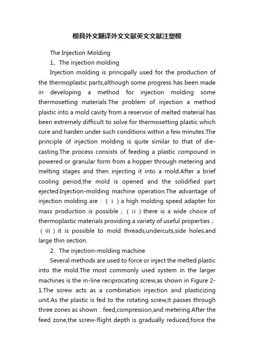
模具外文翻译外文文献英文文献注塑模The Injection Molding1、The injection moldingInjection molding is principally used for the production of the thermoplastic parts,although some progress has been made in developing a method for injection molding some thermosetting materials.The problem of injection a method plastic into a mold cavity from a reservoir of melted material has been extremely difficult to solve for thermosetting plastic which cure and harden under such conditions within a few minutes.The principle of injection molding is quite similar to that of die-casting.The process consists of feeding a plastic compound in powered or granular form from a hopper through metering and melting stages and then injecting it into a mold.After a brief cooling period,the mold is opened and the solidified part ejected.Injection-molding machine operation.The advantage of injection molding are:(ⅰ)a high molding speed adapter for mass production is possible;(ⅱ)there is a wide choice of thermoplastic materials providing a variety of useful properties;(ⅲ)it is possible to mold threads,undercuts,side holes,and large thin section.2、The injection-molding machineSeveral methods are used to force or inject the melted plastic into the mold.The most commonly used system in the larger machines is the in-line reciprocating screw,as shown in Figure 2-1.The screw acts as a combination injection and plasticizing unit.As the plastic is fed to the rotating screw,it passes through three zones as shown:feed,compression,and metering.After the feed zone,the screw-flight depth is gradually reduced,force theplastic to compress.The work is converted to heat by conduction from the barrel surface.As the chamber in front of the screw becomes filled,it forces the screw back,tripping a limit switch that activates a hydraulic cylinder that forces the screw forward and injects the fluid plastic into the closed mold.An antiflowback valve presents plastic under pressure from escaping back into the screw flight.The clamping force that a machine is capable of exerting is part of the size designation and is measured in tons.A rule-of-thumb can be used to determine the tonnage required for a particular job.It is based on two tons of clamp force per square inch of projected area.If the flow pattern is difficult and the parts are thin,this may have to go to three or four tons.Many reciprocating-screw machines are capable of handing thermosetting plastic materials.Previously these materials were handled by compression or transfer molding.Thermosetting materials cure or polymerize in the mold and are ejected hot in the range of 375°C~410°C.T hermosetting parts must be allowed to cool in the mold in order or remove them without distortion. Thus thermosetting cycles can be faster.Of course the mold must be heated rather than chilled,as with thermoplastics.3、Basic Underfeed MouldA simple mould of this type is shown in Figure3-1,and the description of the design and the opening sequence follows.The mould consists of three basic parts,namely:the moving half,the floating cavity plate and the feed plate respectively.The moving half consists of The moving mould plate assembly,support block,backing plate,ejector assembly and the pin ejection system.Thus the moving half in this design is identical with the moving half of basic moulds.The floating cavity plate,which may be of the integer or insert-bolster design,is located on substantial guide pillars(not shown)fitted in the feed plate.These guide pillars must be of sufficient length to support the floating cavity plate over its full movement and still project to perform the function of alignment between the cavity and core when the mould is being closed.Guide bushes are fitted into the moving mould plate and the floating cavity plate respectively.The maximum movement of the floating cavity plate is controlled by stop or similar device.The moving mould plate is suitably bored to provide a clearance for the stop bolt assembly.The stop bolts must be long enough to provide sufficient space between the feed plate and the floating cavity plate for easy removal of the feed system.The minimum space provide for should be 65mm just sufficient for an operator to remove the feed system by hand if necessary.The desire operating sequence is for the first daylight to occur between the floating cavity plate.This ensures the sprue is pulled from the sprue bush immediately the mouldis opened.T o achieve this sequence,springs may be incorporated between the feed plate and the floating cavity plate.The springs should be strong enough to give an initial impetus to the floating cavity plate to ensure it moves away with the moving half.It is normal practice to mount the springs on the guide pillars(Figure3-2)and accommodate them in suitable pocket in the cavity plate.The major part of the feed system(runner and sprue)is accommodated in the feed plate to facilitate automatic operation,the runner should be of a trapezoidal form so that once it is pulled from the feed plate is can easily beextracted.Note that if a round runner is used,half the runner is formed in the floating cavity plate,where it would remain,and be prevented from falling or being wiped clear when the mould is opened.Now that we have considered the mould assembly in the some detail,we look at the cycle of operation for this type of mould.The impressions are filled via the feed system(Figure3-1(a))and after a suitable dwell period,the machine platens commence to open.A force is immediately exerted by the compression springs,which cause the floating cavity plate to move away with the moving half as previously discussed.The sprue is pulled from the sprue bush by the sprue puller.After the floating cavity plate has moved a predetermined distance,it is arrested by the stop bolts.The moving half continues to move back and the moldings,having shrunk on to the cores,are withdrawn from the cavities.The pin gate breaks at its junction with the runner(Figure3-1(b)).The sprue puller,being attached to the moving half,is pulled through the floating cavity plate and thereby release the feed system which is then free to fall between the floating cavity plate and the feed plate.The moving half continues to move back until the ejector system is operated and the moldings are ejected (Figure3-1(c)).When the mould is closed,the respective plates are returned to their molding position and the cycle is repeated.4、Feed SystemIt is necessary to provide a flow-way in the injection mould to connect the nozzle(of the injection machine)to each impression.This flow-way is termed the feed system.Normally thefeed system comprises a sprue,runner and gate.These terms applyequally to the flow-way itself,and to the molded material which is remove from the flow-way itself in the process of extracted the molding.A typical feed system for a four-impression,two plate-type mould is shown in Figure4-1.It is seen that the material passes through the sprue,main runner,branch runner and gate before entering the impression.As the temperature of molten plastic is lowered which going through the sprue and runner,the viscosity will rise;however,the viscosity is lowered by shear heat generated when going through the gate to fill the cavity.It is desirable to keep the distance that the material has to travel down to a minimum to reduce pressure and heat losses.It is for this reason that careful consideration must be given to the impression layout gate’s design.4.1.SprueA sprue is a channel through which to transfer molten plastic injected from the nozzle of the injector into the mold.It is a part of sprue bush,which is a separate part from the mold.4.2.RunnerA runner is a channel that guides molten plastic into the cavity of a mold.4.3.GateA gate is an entrance through which molten plastic enters the cavity.The gate has the following function:restricts the flow and the direction of molten plastic;simplifies cutting of a runner and moldings to simplify finishing of parts;quickly cools and solidifies to avoid backflow after molten plastic has filled up in the cavity.4.4.Cold slug wellThe purpose of the cold slug well,shown opposite the sprue,is theoretically to receive the material that has chilled at the front of nozzle during the cooling and ejection phase.Perhaps of greater importance is the fact that it provides position means whereby the sprue bush for ejection purposes.The sprue,the runner and the gate will be discarded after a part is complete.However,the runner and the gate are important items that affect the quality or the cost of parts.5、EjectionA molding is formed in mould by injecting a plastic melt,under pressure,into animpression via a feed system.It must therefore be removed manually.Furthermore,all thermoplastic materials contract as they solidify,which means that the molding will shrink on to the core which forms it.This shrinkage makes the molding difficult to remove. Facilities are provided on the injection machine for automatic actuation of an ejector system,and this is situated behind the moving platen.Because of this,the mould’s ejector system will be most effectively operated if placed in the moving half of the mould,i.e. the half attached to the moving platen.We have stated previously that we need to eject the molding from the core and it therefore follows that the core,too,will most satisfactorily be located in the moving half.The ejector system in a mould will be discussed under three headings,namely:(ⅰ)the ejector grid;(ⅱ)the ejector plate assembly; and(ⅲ)the method of ejection.5.1、Ejector gridThe ejector grid(Figure5-1)is that part of the mould which supports the mould plate and provides a space into which theejector plate assembly can be fitted and operated.The grid normally consists of a back plate on to which is mounted a number of conveniently shaped “support blocks”.The ejector plate assembly is that part of the mould to which the ejector element is attached.The assembly is contained in a pocket,formed by the ejector grid,directly behind the mould plate.The assembly(Figure5-2)consists of an ejector plate,a retaining plate and an ejector rod.One end of this latter member is threaded and it is screwed into the ejector plate.In this particular design the ejector rod function not only as an actuating member but also as a method of guiding the assembly.Note that the parallel portion of the ejector rod passes through an ejector rod bush fitted in the back plate of the mould.5.2、Ejection techniquesWhen a molding cools,it contracts by an amount depending on the material being processed.For a molding which has no internal form,for example,a solid rectangular block,the molding will shrink away from the cavity walls,thereby permitting a simple ejection technique to be adopted.However,when the molding has internal form,the molding,as it cools,will shrink onto the core and some positive type of ejection is necessary.The designer has several ejection techniques from which to choose,but in general,the choice will be restricted depending upon the shape of the molding.The basic ejection techniques are as follows:(ⅰ)pin ejection(ⅱ)sleeve ejection(ⅲ)stripper plate ejection and(Ⅳ)air ejection.Figure 2-1aFigure 2-1bFigure 3-1Figure 3-2Figure 4-1aFigure 4-1bFigure 5-1Figure 5-2注塑模1、注塑模尽管成型某些热固性材料的方法取得了一定的进步,但注塑模主要(还是)用来生产热塑性塑件。
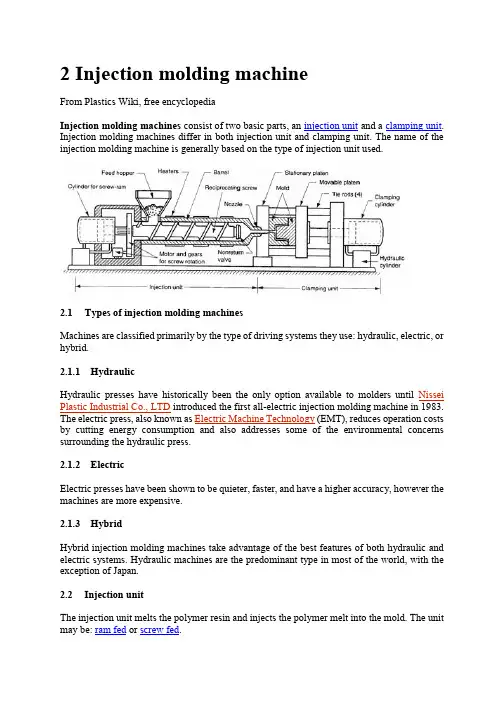
2 Injection molding machineFrom Plastics Wiki, free encyclopediaInjection molding machines consist of two basic parts, an injection unit and a clamping unit. Injection molding machines differ in both injection unit and clamping unit. The name of the injection molding machine is generally based on the type of injection unit used.2.1Types of injection molding machinesMachines are classified primarily by the type of driving systems they use: hydraulic, electric, or hybrid.2.1.1HydraulicHydraulic presses have historically been the only option available to molders until Nissei Plastic Industrial Co., LTD introduced the first all-electric injection molding machine in 1983. The electric press, also known as Electric Machine Technology (EMT), reduces operation costs by cutting energy consumption and also addresses some of the environmental concerns surrounding the hydraulic press.2.1.2ElectricElectric presses have been shown to be quieter, faster, and have a higher accuracy, however the machines are more expensive.2.1.3HybridHybrid injection molding machines take advantage of the best features of both hydraulic and electric systems. Hydraulic machines are the predominant type in most of the world, with the exception of Japan.2.2Injection unitThe injection unit melts the polymer resin and injects the polymer melt into the mold. The unit may be: ram fed or screw fed.The ram fed injection molding machine uses a hydraulically operated plunger to push the plastic through a heated region. The high viscosity melt is then spread into a thin layer by a "torpedo" to allow for better contact with the heated surfaces. The melt converges at a nozzle and is injected into the mold.Reciprocating screw A combination melting, softening, and injection unit in an injection molding machine. Another term for the injection screw. Reciprocating screws are capable of turning as they move back and forth.The reciprocating screw is used to compress, melt, and convey the material. The reciprocating screw consists of three zones (illustrated below):•feeding zone•compressing zone•metering zoneWhile the outside diameter of the screw remains constant, the depth of the flights on the reciprocating screw decreases from the feed zone to the beginning of the metering zone. These flights compress the material against the inside diameter of the barrel, which creates viscous (shear) heat. This shear heat is mainly responsible for melting the material. The heater bands outside the barrel help maintain the material in the molten state. Typically, a molding machine can have three or more heater bands or zones with different temperature settings.Injection molding reciprocating screw An extruder-type screw rotates within a cylinder, which is typically driven by a hydraulic drive mechanism. Plastic material is moved through the heated cylinder via the screw flights and the material becomes fluid. The injection nozzle is blocked by the previous shot, and this action causes the screw to pump itself backward through the cylinder. (During this step, material is plasticated and accumulated for the next shot.) When the mold clamp has locked, the injection phase takes place. At this time, the screw advances, acting as a ram. Simultaneously, the non-return valve closes off the escape passages in the screw and the screw serves as a solid plunger, moving the plastic ahead into the mold. When the injection stroke and holding cycle is completed, the screw is energized to return and the non-return valve opens, allowing plastic to flow forward from the cylinder again, thus repeating the cycle.2.2.1Feed hopperThe container holding a supply molding material to be fed to the screw. The hopper located over the barrel and the feed throat connects them.2.2.2Injection ramThe ram or screw that applies pressure on the molten plastic material to force it into the mold cavities.2.2.3Injection screwThe reciprocating-screw machine is the most common. This design uses the same barrel for melting and injection of plastic.The alternative unit involves the use of separate barrels for plasticizing and injecting the polymer. This type is called a screw-preplasticizer machine or two-stage machine. Plastic pellets are fed from a hopper into the first stage, which uses a screw to drive the polymer forward and melt it. This barrel feeds a second barrel, which uses a plunger to inject the melt into the mold. Older machines used one plunger-driven barrel to melt and inject the plastic. These machines are referred to as plunger-type injection molding machines.2.2.4BarrelBarrel is a major part that melts resins transmitted from hopper through screws and structured in a way that can heat up resins to the proper temperature. A band heater, which can control temper atures in five sections, is attached outside the barrel. Melted resins are supplied to the mold passing through barrel head, shot-off nozzle, and one-touch nozzle.2.2.5Injection cylinderHydraulic motor located inside bearing box, which is connected to injection cylinder load, rotates screw, and the melted resins are measures at the nose of screw. There are many types of injection cylinders that supply necessary power to inject resins according to the characteristics of resins and product types at appropriate speed and pressure. This model employs the double cylinder type. Injection cylinder is composed of cylinder body, piston, and piston load.2.3Clamping unitThe clamping unit holds the mold together, opens and closes it automatically, and ejects the finished part. The mechanism may be of several designs, either mechanical, hydraulic or hydromechanical.Toggle clamps - a type clamping unit include various designs. An actuator moves the crosshead forward, extending the toggle links to push the moving platen toward a closed position. At the beginning of the movement, mechanical advantage is low and speed is high; but near the end of the stroke, the reverse is true. Thus, toggle clamps provide both high speed and high force at different points in the cycle when they are desirable. They are actuated either by hydraulic cylinders or ball screws driven by electric motors. Toggle-clamp units seem most suited to relatively low-tonnage machines.Two clamping designs: (a) one possible toggle clamp design (1) open and (2) closed; and (b) hydraulic clamping (1) open and (2) closed. Tie rods used to guide movuing platens not shown.Hydraulic clamps are used on higher-tonnage injection molding machines, typically in the range 1300 to 8900 kN (150 to 1000 tons). These units are also more flexible than toggle clamps in terms of setting the tonnage at given positions during the stroke.Hydraulic Clamping System is using the direct hydraulic clamp of which the tolerance is still and below 1 %, of course, better than the toggle system. In addition, the Low Pressure Protection Device is higher than the toggle system for 10 times so that the protection for the precision and expensive mold is very good. The clamping force is focus on the central for evenly distribution that can make the adjustment of the mold flatness in automatically. Hydromechanical clamps -clamping units are designed for large tonnages, usually above 8900 kN (1000 tons); they operate by (1) using hydraulic cylinders to rapidly move the mold toward closing position, (2) locking the position by mechanical means, and (3) using high pressure hydraulic cylinders to finally close the mold and build tonnage.2.3.1Injection moldThere are two main types of injection molds: cold runner (two plate and three plate designs) and hot runner– the more common of the runnerless molds.2.3.2Injection platensSteel plates on a molding machine to which the mold is attached. Generally, two platens are used; one being stationary and the other moveable, actuated hydraulically to open and close the mold. It actually provide place to mount the mould. It contains threaded holes on which mould can be mounted using clamps.2.3.3Clamping cylinderA device that actuates the chuck through the aid of pneumatic or hydraulic energy.2.3.4Tie BarTie bars support clamping power, and 4 tie bars are located between the fixing platen and the support platen.3 Injection mouldFrom Wikipedia, the free encyclopediaMold A hollow form or cavity into which molten plastic is forced to give the shape of the required component. The term generally refers to the whole assembly of parts that make up the section of the molding equipment in which the parts are formed. Also called a tool or die. Moulds separate into at least two halves (called the core and the cavity) to permit the part to be extracted; in general the shape of a part must be such that it will not be locked into the mould. For example, sides of objects typically cannot be parallel with the direction of draw (the direction in which the core and cavity separate from each other). They are angled slightly; examination of most household objects made from plastic will show this aspect of design, known as draft. Parts that are "bucket-like" tend to shrink onto the core while cooling and, after the cavity is pulled away, are typically ejected using pins. Parts can be easily welded together after moulding to allow for a hollow part (like a water jug or doll's head) that couldn't physically be designed as one mould.More complex parts are formed using more complex moulds, which may require moveable sections, called slides, which are inserted into the mould to form particular features that cannot be formed using only a core and a cavity, but are then withdrawn to allow the part to be released. Some moulds even allow previously moulded parts to be re-inserted to allow a new plastic layer to form around the first part. This system can allow for production of fully tyred wheels.Traditionally, moulds have been very expensive to manufacture; therefore, they were usually only used in mass production where thousands of parts are being produced.Molds require: Engineering and design, special materials, machinery and highly skilled personnel to manufacture, assemble and test them.Cold-runner moldCold-runner mold Developed to provide for injection of thermoset material either directly into the cavity or through a small sub-runner and gate into the cavity. It may be compared to the hot-runner molds with the exception that the manifold section is cooled rather than heated to maintain softened but uncured material. The cavity and core plates are electrically heated to normal molding temperature and insulated from the cooler manifold section.3.1.1Types of Cold Runner MoldsThere are two major types of cold runner molds: two plate and three plate.3.1.2Two plate moldA two plate cold runner mold is the simplest type of mold. It is called a two plate mold because there is one parting plane, and the mold splits into two halves. The runner system must be located on this parting plane; thus the part can only be gated on its perimeter.3.1.3Three plate moldA three plate mold differs from a two plate in that it has two parting planes, and the mold splits into three sections every time the part is ejected. Since the mold has two parting planes, the runner system can be located on one, and the part on the other. Three plate molds are used because of their flexibility in gating location. A part can be gated virtually anywhere along its surface.3.1.4AdvantagesThe mold design is very simple, and much cheaper than a hot runner system. The mold requires less maintenance and less skill to set up and operate. Color changes are also very easy, since all of the plastic in the mold is ejected with each cycle.3.1.5DisadvantagesThe obvious disadvantage of this system is the waste plastic generated. The runners are either disposed of, or reground and reprocessed with the original material. This adds a step in the manufacturing process. Also, regrind will increase variation in the injection molding process, and could decrease the plastic's mechanical properties.3.1.6Hot runner moldHot-runner mold -injection mold in which the runners are kept hot and insulated from the chilled cavities. Plastic freezeoff occurs at gate of cavity; runners are in a separate plate so they are not, as is the case usually, ejected with the piece.Hot runner molds are two plate molds with a heated runner system inside one half of the mold.A hot runner system is divided into two parts: the manifold and the drops. The manifold has channels that convey the plastic on a single plane, parallel to the parting line, to a point abovethe cavity. The drops, situated perpendicular to the manifold, convey the plastic from the manifold to the part.3.1.7Types of Hot Runner MoldsThere are many variations of hot runner systems. Generally, hot runner systems are designated by how the plastic is heated. There are internally and externally heated drops and manifolds.3.1.8Externally heated hot runnersExternally heated hot runner channels have the lowest pressure drop of any runner system (because there is no heater obstructing flow and all the plastic is molten), and they are better for color changes none of the plastic in the runner system freezes. There are no places for material to hang up and degrade, so externally heated systems are good for thermally sensitive materials.3.1.9Internally heated hot runnersInternally heated runner systems require higher molding pressures, and color changes are very difficult. There are many places for material to hang up and degrade, so thermally sensitive materials should not be used. Internally heated drops offer better gate tip control. Internally heated systems also better separate runner heat from the mold because an insulating frozen layer is formed against the steel wall on the inside of the flow channels.3.1.10 insulated hot runnersA special type of hot runner system is an insulated runner. An insulated runner is not heated; the runner channels are extremely thick and stay molten during constant cycling. This system is very inexpensive, and offers the flexible gating advantages of other hot runners and the elimination of gates without the added cost of the manifold and drops of a heated hot runner system. Color changes are very easy. Unfortunately, these runner systems offer no control, and only commodity plastics like PP and PE can be used. If the mold stops cycling for some reason, the runner system will freeze and the mold has to be split to remove it. Insulated runners are usually used to make low tolerance parts like cups and frisbees.3.1.11 DisadvantagesHot-runner mold is much more expensive than a cold runner, it requires costly maintenance, and requires more skill to operate. Color changes with hot runner molds can be difficult, since it is virtually impossible to remove all of the plastic from an internal runner system.3.1.12 AdvantagesThey can completely eliminate runner scrap, so there are no runners to sort from the parts, and no runners to throw away or regrind and remix into the original material. Hot runners are popular in high production parts, especially with a lot of cavities.Advantages Hot Runner System Over a Cold Runner System include:•no runners to disconnect from the molded parts•no runners to remove or regrind, thus no need for process/ robotics to remove them•having no runners reduces the possibility of contamination•lower injection pressures•lower clamping pressure•consistent heat at processing temperature within the cavity•cooling time is actually shorter (as there is no need for thicker, longer-cycle runners)•shot size is reduced by runner weight•cleaner molding process (no regrinding necessary)•nozzle freeze and sprue sticking issues eliminated中文翻译注塑模具设计与制造2 注射机选自《维基百科》注射机由两个基本部分组成,注射装置和夹紧装置。
注塑模具外文翻译参考资料China's mold industry and its development trendDue to historical reasons for the formation of closed, "big and complete" enterprise features, most enterprises in China are equipped with mold workshop, in factory matching status since the late 70s have a mold the concept of industrialization and specialization of production. Production efficiency is not high, poor economic returns. Mold production industry is small and scattered, cross-industry, capital-intensive, professional, commercial and technical management level are relatively low.According to incomplete statistics, there are now specialized in manufacturing mold, the product supporting mold factory workshop (factory) near 17 000, about 600 000 employees, annual output value reached 20 billion yuan mold. However, the existing capacity of the mold and die industry can only meet the demand of 60%, still can not meet the needs of national economic development. At present, the domestic needs of large, sophisticated, complex and long life of the mold also rely mainly on imports. According to customs statistics, in 1997 630 million U.S. dollars worth of imports mold, not including the import of mold together with the equipment; in 1997 only 78 million U.S. dollars export mold. At present the technological level of China Die & Mould Industry and manufacturing capacity, China's national economy in the weak links and bottlenecks constraining sustainable economic development.Technical level of China's mold industry currently uneven, with wide disparities. Generally speaking, with the developed industrial countries, Hong Kong and Taiwan advanced level, there is a large gap.The use of CAD / CAM / CAE / CAPP and other technical design and manufacture molds, both wide application, or technical level, there is a big gap between both. In the application of CAD technology design molds, only about 10% of the mold used in the design of CAD, aside from drawing board still has a long way to go; in the application of CAE design and analysis of mold calculation, it was just started, most of the game is still in trial stages and animation; in the application of CAM technology manufacturing molds, first, the lack of advanced manufacturing equipment, and second, the existing process equipment (including the last 10 years the introduction of advanced equipment) or computer standard (IBM PC and compatibles, HP workstations, etc.) different, or because of differences in bytes, processing speed differences, differences in resistance to electromagnetic interference, networking is low, only about 5% of the mold manufacturing equipment of recent work in this task; in the application process planning CAPP technology, basically a blank state, based on the need for a lot of standardization work; in the mold common technology, such as mold rapid prototyping technology, polishing, electroforming technologies, surface treatment technology aspects of CAD / CAM technology in China has just started. Computer-aided technology, software development, is still atlow level, the accumulation of knowledge and experience required. Mostof our mold factory, mold processing equipment shop old, long in the length of civilian service, accuracy, low efficiency, still use the ordinary forging, turning, milling, planing, drilling, grinding and processing equipment, mold, heat treatment is still in use salt bath, box-type furnace, operating with the experience of workers, poorly equipped, high energy consumption. Renewal of equipment is slow, technological innovation, technological progress is not much intensity. Although in recent years introduced many advanced mold processing equipment, but are too scattered, or not complete, only about 25% utilization, equipment, some of the advanced functions are not givenfull play.Lack of technology of high-quality mold design, manufacturing technology and skilled workers, especially the lack of knowledge and breadth, knowledge structure, high levels of compound talents. China's mold industry and technical personnel, only 8% of employees 12%, and the technical personnel and skilled workers and lower the overall skill level. Before 1980, practitioners of technical personnel and skilled workers, the aging of knowledge, knowledge structure can not meet the current needs; and staff employed after 80 years, expertise, experience lack of hands-on ability, not ease, do not want to learn technology. In recent years, the brain drain caused by personnel not only decrease the quantity and quality levels, and personnelstructure of the emergence of new faults, lean, make mold design, manufacturingdifficult to raise the technical level.我国模具工业现状及发展趋势由于历史原因形成的封闭式、“大而全”的企业特征,我国大部分企业均设有模具车间,处于本厂的配套地位,自70年代末才有了模具工业化和生产专业化这个概念。
中英文资料对照外文翻译英文:Design and Technology of the Injection Mold1、3D solid model to replace the center layer modelThe traditional injection molding simulation software based on products of the center layer model. The user must first be thin-walled plastic products abstract into approximate plane and curved surface, the surface is called the center layer. In the center layer to generate two-dimensional planar triangular meshes, the use of these two-dimensional triangular mesh finite element method, and the final result of the analysis in the surface display. Injection product model using3D solid model, the two models are inconsistent, two modeling inevitable. But because of injection molding product shape is complex and diverse, the myriads of changes from athree-dimensional entity, abstraction of the center layer is a very difficult job, extraction process is very cumbersome and time-consuming, so the design of simulation software have fear of difficulty, it has become widely used in injection molding simulation software the bottleneck.HSCAE3D is largely accepted3D solid / surface model of the STL file format. Now the mainstream CAD/CAM system, such as UG, Pro/ENGINEER, CATIA and SolidWorks, can output high quality STL format file. That is to say, the user can use any commercial CAD/CAE systems to generate the desired products3D geometric model of the STL format file, HSCAE3D can automatically add the STL file into a finite element mesh model, through the surface matching and introduction of a new boundary conditions to ensure coordination of corresponding surface flow, based on3D solid model of analysis, and display of three-dimensional analysis results, replacing the center layer simulation technology to abstract the center layer, and then generate mesh this complicated steps, broke through system simulation application bottlenecks, greatly reducing the burden of user modeling, reduces the technical requirement of the user, the user training time from the past few weeks shorter for a fewhours. Figure 1 is based on the central layer model and surface model based on 3D solid / flow analysis simulation comparison chart.2、Finite element, finite difference, the control volume methodsInjection molding products are thin products, products in the thickness direction of size is much smaller than the other two dimensions, temperature and other physical quantities in the thickness direction of the change is very large, if the use of a simple finite element and finite difference method will cause analysis time is too long, can not meet the actual needs of mold design and manufacturing. We in the flow plane by using finite element method, the thickness direction by using finite difference method, were established and plane flow and thickness directions corresponding to the size of the grid and coupling, while the accuracy is guaranteed under the premise of the calculation speed to meet the need of engineering application, and using the control volume method is solved. The moving boundary problem in. For internal and external correspondence surface differences between products, can be divided into two parts the volume, and respectively formed the control equation, the junction of interpolation to ensure thatthe two part harmony contrast.3、Numerical analysis and artificial intelligence technologyOptimization of injection molding process parameters has been overwhelming majority of mold design staff concerns, the traditional CAE software while in computer simulation of a designated under the conditions of the injection molding conditions, but is unable to automatically optimize the technical parameters. Using CAE software personnel must be set to different process conditions were multiple CAE analysis, combined with practical experience in the program were compared between, can get satisfactory process scheme. At the same time, the parts after the CAE analysis, the system will generate a large amount of information about the project ( product, process, analyzes the results ), which often results in a variety of data form, requiring the user to have the analysis and understanding of the results of CAE analysis ability, so the traditional CAE software is a kind of passive computational tools, can provide users with intuitionistic, effective engineering conclusion, to software users demand is too high, the influence of CAE system in the larger scope of application and popularization. In view of the above, HSCAE3D software in the original CAE system based on accurate calculationfunction, the knowledge engineering technology is introduced the system development, the use of artificial intelligence is the ability of thinking and reasoning, instead of the user to complete a large number of information analysis and processing work, directly provide guiding significance for the process of conclusions and recommendations, effectively solve the CAE of the complexity of the system and the requirements of the users of the contradiction between, shortening of the CAE system and the distance between the user, the simulation software by traditional " passive" computational tools to " active" optimization system. HSCAE3D system artificial intelligence technology will be applied to the initial design, the results of the analysis of CAE interpretation and evaluation, improvement and optimization analysis of3 aspects.译文:注塑模具设计的技术1.用三维实体模型取代中心层模型传统的注塑成形仿真软件基于制品的中心层模型。
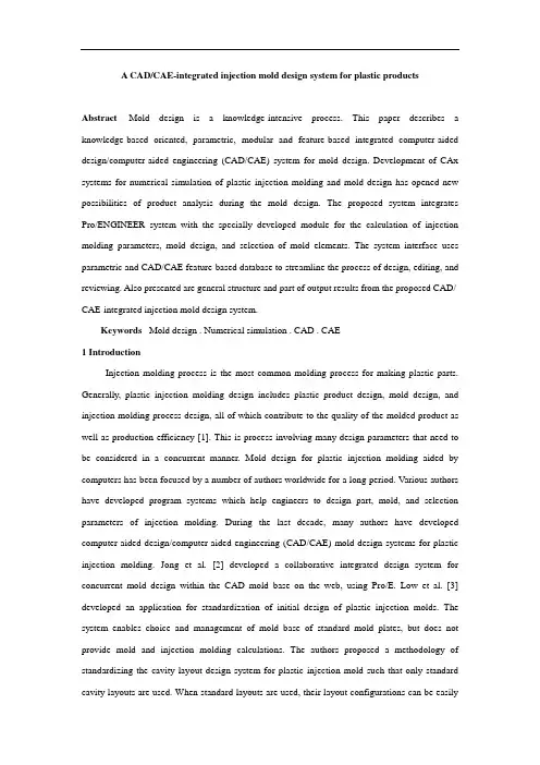
A CAD/CAE-integrated injection mold design system for plastic productsAbstract Mold design is a knowledge-intensive process. This paper describes a knowledge-based oriented, parametric, modular and feature-based integrated computer-aided design/computer-aided engineering (CAD/CAE) system for mold design. Development of CAx systems for numerical simulation of plastic injection molding and mold design has opened new possibilities of product analysis during the mold design. The proposed system integrates Pro/ENGINEER system with the specially developed module for the calculation of injection molding parameters, mold design, and selection of mold elements. The system interface uses parametric and CAD/CAE feature-based database to streamline the process of design, editing, and reviewing. Also presented are general structure and part of output results from the proposed CAD/ CAE-integrated injection mold design system.Keywords Mold design . Numerical simulation . CAD . CAE1 IntroductionInjection molding process is the most common molding process for making plastic parts. Generally, plastic injection molding design includes plastic product design, mold design, and injection molding process design, all of which contribute to the quality of the molded product as well as production efficiency [1]. This is process involving many design parameters that need to be considered in a concurrent manner. Mold design for plastic injection molding aided by computers has been focused by a number of authors worldwide for a long period. Various authors have developed program systems which help engineers to design part, mold, and selection parameters of injection molding. During the last decade, many authors have developed computer-aided design/computer-aided engineering (CAD/CAE) mold design systems for plastic injection molding. Jong et al. [2] developed a collaborative integrated design system for concurrent mold design within the CAD mold base on the web, using Pro/E. Low et al. [3] developed an application for standardization of initial design of plastic injection molds. The system enables choice and management of mold base of standard mold plates, but does not provide mold and injection molding calculations. The authors proposed a methodology of standardizing the cavity layout design system for plastic injection mold such that only standard cavity layouts are used. When standard layouts are used, their layout configurations can be easilystored in a database. Lin at al. [4, 5] describe a structural design system for 3D drawing mold based on functional features using a minimum set of initial information. In addition, it is also applicable to assign the functional features flexibly before accomplishing the design of a solid model for the main parts of a drawing mold. This design system includes modules for selection and calculation of mold components. It uses Pro/E modules Pro/Program and Pro/Toolkit, and consists of modules for mold selection, modification and design. Deng et al. [6, 7] analyzed development of the CAD/CAE integration. The authors also analyzed systems and problems of integration between CAD and CAE systems for numerical simulation of injection molding and mold design. Authors propose a feature ontology consisting of a number of CAD/CAE features. This feature represents not only the geometric information of plastic part, but also the design intent is oriented towards analysis. Part features contain the overall product information of a plastic part, wall features, development features (such as chamfer, ribs, boss, hole, etc.), treatment features which contain analysis-related design information and sub wall developed features. Wall and development features are so called “component features〞. God ec et al. [8, 9] developed a CAE system for mold design and injection molding parameters calculations. The system is based on morphology matrix and decision diagrams. The system is used for thermal, rheological and mechanical calculation, and material base management,Fig. 1 General structure of integrated injection mold design system for plastic productsbut no integration with commercial CAx software is provided. Huang et al. [10] developed a mold-base design system for injection molding. The database they used was parametric and feature-based oriented. The system used Pro/E for modeling database components. Kong et al. [11]developed a parametric 3D plastic injection mold design system integrated with solid works. Other knowledge-based systems, such as IMOLD, ESMOLD, IKMOULD, and IKBMOULD, have been developed for injection mold design. IMOLD divides mold design into four major steps; parting surface design, impression design, runner system design, and mold-base design. The software uses a knowledge-based CAD system to provide an interactive environment, assist designers in the rapid completion of mold design, and promote the standardization of the mold design process. IKB-MOULD application consists of databases and knowledge bases for mold manufacturing. Lou et al. [12] developed an integrated knowledge-based system for mold base design. The system has module for impression calculation, dimension calculation, calculation of the number of mold plates and selection of injection machine. The system uses Pro/ Mold Base library. This paper describes KBS and key technologies, such as product modeling, the frame-rule method, CBS, and the neural networks. A multilayer neural network has been trained by back propagation BP. This neural network adopts length, width, height and the number of parts in the mold as input and nine parameters (length, width, and height of up and down set-in, mold bases side thickness, bottom thickness of the core, and cavity plates) as output. Mok et al. [13, 14] developed an intelligent collaborative KBS for injection molds. Mok at el. [15] has developed an effective reuse and retrieval system that can register modeled standard parts using a simple graphical user interface even though designers may not know the rules of registration for a database. The mold design system was developed using an Open API and commercial CAD/computer aided manufacturing (CAM)/CAE solution. The system was applied to standardize mold bases and mold parts in Hyundai Heavy Industry. This system adopted the method of design editing, which implements the master model using features. The developed system provides methods whereby designers can register the master model, which is defined as a function of 3D CAD, as standard parts and effectively reuse standard parts even though they do not recognize the rules of the database.Todic et al. [16] developed a software solution for automated process planning for manufacturing of plastic injection molds. This CAD/CAPP/CAM system does not provide CAE calculation of parameters of injection molding and mold design. Maican et al. [17] used CAE for mechanical, thermal, and rheological calculations. They analyzed physical, mechanical, and thermal properties of plastic materials. They defined the critical parameters of loaded part. Nardinet al. [18] tried to develop the system which would suit all the needs of the injection molding for selection of the part–mold–technology system. The simulation results consist of geometrical and manufacturing data. On the basis of the simulation results, part designers can optimize part geometry, while mold designers can optimize the running and the cooling system of the mold. The authors developed a program which helps the programmers of the injection molding machine to transfer simulation data directly to the machine. Zhou et al. [1] developed a virtual injection molding system based on numerical simulation. Ma et al. [19] developed standard component library for plastic injection mold design using an object-oriented approach. This is an objector iented, library model for defining mechanical components parametrically. They developed an object-oriented mold component library model for incorporating different geometric topologies and non-geometric information. Over the years, many researchers have attempted to automate a wholeFig. 2 Structure of module for numerical simulation of injection molding processFig. 3 Forms to define the mold geometrymold design process using various knowledge-based engineering (KBE) approaches, such as rule-based reasoning (RBR), and case base (CBR) and parametric design template (PDT). Chan at al. [20] developed a 3D CAD knowledge-based assisted injection mold design system (IKB mold). In their research, design rules and expert knowledge of mold design were obtained from experienced mold designers and handbooks through various traditional knowledge acquisition processes. The traditional KBE approaches, such as RBR, CBR, and simple PDT have been successfully applied to mold cavity and runner layout design automation of the one product mold. Ye et al. [21] proposed a feature-based and object-oriented hierarchical representation and simplified symbolic geometry approach for automation mold assembly modeling. The previously mentioned analysis of various systems shows that authors used different ways to solve the problems of mold design by reducing it to mold configureator (selector). They used CAD/CAE integration for creating precision rules for mold-base selection. Many authors used CAE system for numerical simulation of injection molding to define parameters of injection molding. Several also developed original CAE modules for mold and injection molding process calculation. However, common to all previously mentioned systems is the lack of module for calculation of mold and injection molding parameters which would allow integration with the results of numerical simulation. This leads to conclusion that there is a need to create a software system which integrates parameters of injection molding with the result obtained by numericalFig. 4 Forms to determine the distance between the cooling channels and mold cavityFig. 5 Mold-base selector formssimulation of injection molding, mold calculation, and selection. All this would be integrated into CAD/CAE-integrated injection mold design system for plastic products.2 Structure of integrated CAD/CAE systemAs is well known, various computational approaches for supporting mold design systems of various authors use design automation techniques such as KBE (RBR, CBR, PDT) or design optimisation techniques such as traditional (NLP,LP, BB, GBA, IR, HR) or meta heuristic search such as (TS, SA, GA) and other special techniques such as (SPA, AR, ED).The developed interactive software system makes possible to perform: 3D modeling of the parts, analysis of part design and simulation model design, numerical simulation of injection molding, and mold design with required calculations.The system consists of four basic modules:& Module for CAD modeling of the part& Module for numerical simulation of injection molding processFig. 6 Form for mechanical mold calculation& Module for calculation of parameters of injection molding and mold design calculation and selection& Module for mold modeling (core and cavity design and design all residual mold components) The general structure of integrated injection mold design system for plastic products is shown in Fig. 1.2.1 Module for CAD modeling of the part (module I)The module for CAD modeling of the part is the first module within the integrated CAD/CAE system. This module is used for generating CAD model of the plastic product and appropriate simulation model. The result of this module is solid model of plastic part with all necessary geometrical and precision specifications. Precision specifications are: project name, number, feature ID, feature name, position of base point, code number of simulation annealing, trade material name, material grade, part tolerance, machine specification (name, clamping force, maximal pressure, dimensions of work piece), and number of cavity. If geometrical and precision specification is specified (given) with product model, the same are used as input to the nextmodule, while this module is used only to generate the simulation model.2.2 Module for numerical simulation of injection molding process (module II)Module II is used for numerical simulation of injection molding process. User implements an iterative simulation process for determining the mold ability parameters of injection molding and simulation model specification. The structure of this module is shown in Fig. 2.After a product model is imported and a polymer is selected from the plastic material database, user selects the best location for gating subsystem. The database contains rheological, thermal, and mechanical properties of plastic materials. User defines parameters of injection molding and picks the location for the gating subsystem. Further analyses are carried out: the plastic flow, fill time, injection pressure, pressure drop, flow front temperature, presence of weld line, presence of air traps, cooling quality, etc.The module offers four different types of mold flow analysis. Each analysis is aimed at solving specific problems:& Part analysis—This analysis is used to test a known gate location, material, and part geometry to verify that a part will have acceptable processing conditions.& Gate analysis—This analysis tests multiple gate locations and compares the analysis outputs to determine the optimal gate location.& Sink mark analysis—This analysis detects sink mark locations and depths to resolve cosmetic problems before the mold is built eliminating quality disputes that could arise between the molder and the customer.The most important parameters are the following: [22]& Part thickness& Flow length& Radius and drafts,& Thickness transitions& Part material& Location of gates& Number of gates& Mold temperature& Melt temperature& Injection pressure& Maximal injection molding machine pressureIn addition to the previously mentioned parameters of injection molding, the module shows following simulation results: welding line position, distribution of air traps, the distribution of injection molding pressure, shear stressFig. 7 Segment of the mechanical calculation algorithmdistribution, temperature distribution on the surface of the simulation model, the quality of filling of a simulation model, the quality of a simulation model from the standpoint of cooling, and time of injection molding [22, 23]. A part of output results from this module are the input data for thenext module. These output results are: material grade and material supplier, modulus of elasticity in the flow direction, modulus of elasticity transverse direction, injection pressure, ejection temperature, mold temperature, melting temperature, highest melting temperature thermoplastic, thermoplastic density in liquid and solid state, and maximum pressure of injection molding machine. During implementation of iterative SA procedure, user defines the moldability simulation model and the parameters of injection molding. All results are represented by different colors in the regions of the simulation model.2.3 Module for calculation of parameters of injection molding and mold design calculation and selection (module III)This module is used for analytical calculations, mold sizing, and its selection. Two of the more forms for determining the dimensions of core and cavity mold plates are shown in Fig. 3.Based on the dimensions of the simulation model and clamping force (Fig. 3) user selects the mold material and system calculates the width and length of core and cavity plates. Wall thickness between the mold cavity to the cooling channel can be calculated with the following three criteria: criterion allowable shear stress, allowable bending stress criterion, and the criterion of allowable angle isotherms are shown in Fig. 4 [22, 24]. The system adopts the maximum value of comparing the values of wall thickness calculated by previously mentioned criteria.Fig. 8 Forms for standard mold plates selectionFig. 9 Forms for mold plate model generationBased on the geometry of the simulation model, user select shape and mold type. Forms for the selection mold shape, type, and subsystems are shown in Fig. 5. Once these steps are completed, user implements the thermal, rheological, and mechanical calculation of mold specifications. An example of one of the several forms for mechanical mold calculation is shown in Fig. 6.Segment of the algorithm of mechanical calculations is shown in Fig. 7.f max maximal flexure of cavity platef dop allowed displacement of cavity plateε elastic deformationαmin minimal value of shrinkage factorE k modulus of elasticity of cavity plateG shear modulusS k wall thickness distance measuring between cavity and waterlined KT cooling channel diameterAfter the thermal, rheological, and mechanical calculations, user selects mold plates from the mold base. Form for the selection of standard mold plates is shown in Fig. 8. The system calculates the value of thickness of risers, fixed, and movable mold plates (Fig. 8). Based on the calculated dimensions, the system automatically adopts the first major standard value for the thickness of risers, movable, and fixed mold plate. Calculation of the thickness and the adoption of standard values are presented in the form as shown in Fig. 8.The interactive system recommends the required mold plates. The module loads dimensions from the database and generates a solid model of the plate. After the plate selection, the plate is automatically dimensioned, material plate isFig. 10 Structure of module IVassigned, and 3D model and 2D technical drawing are generated on demand. Dimensions of mold component (e.g., fixed plate) are shown in the form for mold plate mode generation, as shown inThe system loads the plate size required from the mold base. In this way, load up any other necessary standard mold plates that make up the mold subassembly. Subassembly mold model made up of instance plates are shown in Fig. 10Then get loaded other components of subsystems as shown in Fig. 5. Subsystem for selection other components include bolts and washers. The way of components selection are based on a production rules by authors and by company “D-M-E〞[25, 26].2.4 Module for mold modeling (core and cavity design and design all residual mold components; module IV)This module is used for CAD modeling of the mold (core and cavity design). This module uses additional software tools for automation creating core and cavity from simulation (reference) model including shrinkage factor of plastics material and automation splitting mold volumes of the fixed and movable plates. The structure of this module is shown in Fig. 11.Additional capability of this module consists of software tools for:& Applying a shrinkage that corresponds to design plastic part, geometry, and molding conditions, which are computed in module for numerical simulation& Make conceptual CAD model for nonstandard plates and mold components& Design impression, inserts, sand cores, sliders and other components that define a shape of molded part& Populate a mold assembly with standard components such as new developed mold base which consists of DME mold base and mold base of enterprises which use this system, and CAD modeling ejector pins, screws, and other components creating corresponding clearance holes& Create runners and waterlines, which dimensions was calculated in module for calculating of parameters of injection molding and mold design calculation and selection& Check interference of components during mold opening, and check the draft surfacesAfter applied dimensions and selection mold components, user loads 3D model of the fixed (core) and movable (cavity) plate. Geometry mold specifications, calculated in the previous module, are automatically integrated into this module, allowing it to generate the final mold assembly. Output from this module receives the complete mold model of the assembly as shown in Fig. 15. Thismodule allowsFig. 11 Subassembly model of moldFig. 12 CAD model of the test Productmodeling of nonstandard and standard mold components that are not contained in the mold base.3 Case studyThe complete theoretical framework of the CAD/CAE-integrated injection mold design system for plastic products was presented in the previous sections. In order to complete this review, the system was entirely tested on a real case study. The system was tested on few examples of similar plastic parts. Based on the general structure of the model of integrated CAD/CAE design system shown in Fig. 1, the authors tested the system on some concrete examples. One of the examples used for verification of the test model of the plastic part is shown in Fig. 12.The module for the numerical simulation of injection molding process defines the optimal location for setting gating subsystem. Dark blue regions indicate the optimal position for setting gating subsystem as shown in Fig. 13.Based on dimensions, shape, material of the case study product (Fig. 11), optimal gating subsystem location (Fig. 13), and injection molding parameters (Table 1), the simulation model shown in Fig. 14 was generated.One of the rules for defining simulation model gate for numerical simulation:IF (tunnel, plastic material, mass) THEN prediction dimension (upper tunnel, length, diameter1, diameter2, radius, angle, etc.)Part of the output results from module II, which are used in module III are shown in Table 1.Fig. 13 Optimal gating subsystem location in the partTable 1 Part of the output results from the module for the numerical simulation of injection molding processMaterial grade and material supplier Acrylonitrile butadiene styrene 780(ABS 780),Kumho Chemicals Inc.Max injection pressure 100 MPaMold temperature 60°C ili 40Melt Temperature 230°CInjection Time 0,39 s 0,2 sInjection Pressure 27,93 MPaRecommended ejection temperature 79°CModulus of elasticity, flow direction for ABS 780 2,600 MPaModulus of elasticity, transverse direction for ABS 780 2,600 MPaPoision ratio in all directions for ABS 780 0.38Shear modulus for ABS 780 942 MPaDensity in liquid state 0.94032 g/cm3Density in solid state 1.047 g/cm3In module III, the system calculates clamping force F=27.9 kN (Fig. 3), cooling channel diameter d KT=6 mm, cooling channel length lKT090 mm (Fig. 4). Given the shape and dimensions of the simulation model, square shape of mold with normal performance was selected as shown in Fig. 5. Selected mold assembly standard series: 1,616, length and width of mold housing 156×156 mm as shown in Fig. 8. In the segment of calculation shown in Fig. 8, mold design system panel recommends the following mold plates:& Top clamping plate N03-1616-20& Bottom clamping plate N04-1616-20& Fixed mold plate (core plate) N10A-1616-36& Movable plate (cavity plate) N10B-1616-36& Support plate N20-1616-26& Risers N30-1616-46& Ejector retainer plate N40-1616-10& Ejector plate N50-1616-12After finishing the fixed and movable mold plates from the standpoint of CAD modeling core and cavity plates, cooling channel, followed by manual selection of other mold standard components such as sprue bush, locating ring, guide pins, guide bush, leading bushing guide, spacer plates, screws (M4×10, M10×100, M10×30, M6×16, M10×30, etc.) and modeling nonstandard mold components (if any) ejector pins, ejector holes, inserts etc. A complete model of the mold assembly with tested simulation model is shown in Fig. 15.Fig. 14 Simulation model of plastic partFig. 15 Model of the mold assembly with tested simulation model4 ConclusionThe objective of this research was to develop a CAD/CAE integrated system for mold design which is based on Pro/ ENGINEER system and uses specially designed and developed modules for mold design. This paper presents a software solution for multiple cavity mold of identical molding parts, the so-called one product mold. The system is dedicated to design of normal types of molds for products whose length and width are substantially greater than product height, i.e., the system is customized for special requirements of mold manufacturers. The proposed system allows full control over CAD/CAE feature parameters which enables convenient and rapid mold modification. The described CAD/CAE modules are feature-based, parametric, based on solid models, and object oriented. The module for numerical simulation of injection molding allows the determination selection of injection molding parameters. The module for calculation of parameters of injection molding process and mold design calculation and selection improves design Fig. 15 Model of the mold assembly with tested simulation model faster, reduces mold design errors, and provides geometric and precision information necessary for complete mold design. The knowledge base of the system can be accessed by mold designers through interactive modules so that their own intelligence and experience can also be incorporated into the total mold design. Manufacture of the part confirms that the developed CAD/CAE system provides correct results and proves to be a confident software tool.Future research will be directed towards three main goals. The first is to develop a system for automation of family mold design. Another line of research is the integration with CAPP system for plastic injection molds manufacturing developed at the Faculty of Technical Sciences. Finally, following current trends in this area, a collaborative system using web technologies and blackboard architecture shall be designed and implemented.塑料制品的CAD / CAE集成的注塑模具设计系统摘要:模具设计是一个知识密集的过程。
外文资料翻译系部:专业:姓名:学号:外文出处:dvanced English literacy course(用外文写)附件:指导老师评语签名:年月日第一篇译文(中文)2.3注射模2.3.1注射模塑注塑主要用于热塑性制件的生产,它也是最古老的塑料成型方式之一。
目前,注塑占所有塑料树脂消费的30%。
典型的注塑产品主要有杯子器具、容器、机架、工具手柄、旋钮(球形捏手)、电器和通讯部件(如电话接收器),玩具和铅管制造装置。
聚合物熔体因其较高的分子质量而具有很高的粘性;它们不能像金属一样在重力流的作用下直接被倒入模具中,而是需要在高压的作用下强行注入模具中。
因此当一个金属铸件的机械性能主要由模壁热传递的速率决定,这决定了最终铸件的晶粒度和纤维取向,也决定了注塑时熔体注入时的高压产生强大的剪切力是物料中分子取向的主要决定力量。
由此所知,成品的机械性能主要受注射条件和在模具中的冷却条件影响。
注塑已经被应用于热塑性塑料和热固性塑料、泡沫部分,而且也已经被改良用于生产反应注塑过程,在此过程中,一个热固树脂系统的两个组成部分在模具中同时被注射填充,然后迅速聚合。
然而大多数注塑被用热塑性塑料上,接下来的讨论就集中在这样的模具上。
典型的注塑周期或流程包括五个阶段(见图2-1):(1)注射或模具填充;(2)填充或压紧;(3)定型;(4)冷却;(5)零件顶出。
图2-1 注塑流程塑料芯块(或粉末)被装入进料斗,穿过一条在注射料筒中通过旋转螺杆的作用下塑料芯块(或粉末)被向前推进的通道。
螺杆的旋转迫使这些芯块在高压下对抗使它们受热融化的料筒加热壁。
加热温度在265至500华氏度之间。
随着压力增强,旋转螺杆被推向后压直到积累了足够的塑料能够发射。
注射活塞迫使熔融塑料从料筒,通过喷嘴、浇口和流道系统,最后进入模具型腔。
在注塑过程中,模具型腔被完全充满。
当塑料接触冰冷的模具表面,便迅速固化形成表层。
由于型芯还处于熔融状态,塑料流经型芯来完成模具的填充。
Effect of gate size on the melt filling behavior and residual stress of injection moldedpartsPengcheng Xie a ,Fengxia Guo a ,Zhiwei Jiao a ,Yumei Ding a ,Weimin Yang a ,b ,⇑a College of Mechanical and Electrical Engineering,Beijing University of Chemical Technology,Beijing 100029,ChinabState Key Laboratory of Organic–Inorganic Composites,Beijing University of Chemical Technology,Beijing 100029,Chinaa r t i c l e i n f o Article history:Received 8March 2013Accepted 28June 2013Available online 20July 2013Keywords:MoldingVisualization Flow behavior Residual stressa b s t r a c tThis paper studies the effects of gate size on the cavity filling pattern and residual stress of injection molded parts.A total of three rectangular gates with different sizes were used.Experiments were carried out by using a dynamic visualization system.A flow visualization mold was specially designed and made for this study.A high-speed video camera was used to record the mold filling phenomena of cavities with different gate size and different processing parameters.In addition,a Stress Viewer was used to charac-terize the residual stress of molded samples.It was found that the undersized gate has many adverse effects on the filling behavior and residual stress of molded parts.With a larger gate,the cavity will be filled faster and residual stress of parts may be smaller.The result of the study also indicates that nozzle temperature and injection rate can significantly affect the above two aspects.Ó2013Elsevier Ltd.All rights reserved.1.IntroductionGating system design is a key link in the process of injection mold design,because as a channel to connect the runner and the cavity,the gate plays a very important role.The design of gate not only affects the melt filling process,but also concerns the demolding process and separation of products and waste,thus affecting the production costs and benefits [1].Gate size as an essential aspect of gate design has very important influence on the quality of part.A gate with suitable dimension should be able to ensure the plastic filling with fast speed and good liquidity [2].And at the packing stage,gate must remain open long enough to inject additional material into the cavity for shrinkage-compensating.Generally,the gate size is established by experience.Cross-sec-tion of gate is typically smaller than that of the runner and parts,thus parts can be easily separated from the runner without leaving a visible scar on the part.In addition,when the material in the gate drops below the freeze temperature,there is the end of packing,therefore,the gate dimension controls the packing time.From these points of view,the overlarge gate is not desirable.In recent years,a large number of studies on gate design were carried out.But there are limited published works on studies relat-ing to design of gate size:Tor et al.[2]used five rectangular gateswith different ratio of width and depth to the impacts of gate size on the quality of powder injection molding.By performing the analysis of weight and density on the samples molded for each of the five gates,they evaluated the impact of different gate size.Shen et al.[3]analyzed the optimal gate design of thin-walled injection molding by using control volume finite element method.Xie and Ziegmann [4]investigated the effect of gate dimension on micro injection molded weld line strength with polypropylene (PP)and high-density polyethylene (HDPE)and found out some relation-ship between gate size and the quality of micro-molded part.This paper aims to intuitively display the influence of gate size on melt flow behavior in cavity,as well as the relationship between gate size and residual stress of parts.As moldings are used in wider areas,higher requirements for precision of products have been constantly put forward.How to suppress the generation of product defects (e.g.jet,weld lines,air bubbles,flash,crazing,etc.)and maximize the dimensional accuracy of products has been an important subject for researchers.Observing the flow behavior as an effective method could help people know the generation princi-ple of defects,and further to find out the causes and even the solu-tions [5].The emergence of visualization injection molding method applied an effective way for observing the phenomenon of melt flow in the mold.Injection molding visualization technology is a technology that the injection molding process can be directly ob-served.It is essentially adding a system that can real-time monitor-ing the filling process and reproducing the melt flow behavior in a conventional injection molding process,thus making the injection molding process from the traditional sense of ‘‘invisible’’becomes ‘‘visualization’’and ‘‘repeatable’’.Up to now,visualization method0261-3069/$-see front matter Ó2013Elsevier Ltd.All rights reserved./10.1016/j.matdes.2013.06.071⇑Corresponding author at:College of Mechanical and Electrical Engineering,Beijing University of Chemical Technology,Beijing 100029,China.Tel./fax:+861064434734.E-mail address:yangwm@ (W.M Yang).has been widely used in multiple studies of injection.Yokoi has carried out a lot of research by this technique,for example,the study of molding process of two-color products,observation of flow front behavior duringfilling process with two-axis tracking system,analysis of thermoset phenolic resinflow behavior by Gate-Magnetization Method,and the study of meltfilling disci-pline of ultra-high speed injection molding[6–10],etc.In addition, by this method,Liu and Wu[11]compared the difference offilling process and molding parts between water-assisted and gas-as-sisted injection molding.Mehdi et al.[12]studied the bubbledynamics in foam injection molding.However,the visualization technology being applied to the gate size has not yet been found, in view of the successful application of it in above-mentioned areas,as well as the significant advantage it had shown,this study will use visualization techniques as one of the main means of research.Besides,defects in the products,such as warping and shrinkage, are detrimental to the quality and accuracy of the products[13]. Actually,an important factor causing these defects is residual stress.In general,the residual stress of injection molded products are divided into two Categories.One is the thermal residual stress, which is resulting during cooling period in the mold and after demolding[14].The other one is referred as residualflow stresses, which is due to the shear and normal stresses duringfilling and packing.Flow-induced stress is smaller than the former,but it could induce anisotropy of optical and some mechanical properties because of different molecular orientation in the directions of par-allel and perpendicular to theflow direction[15].Residual stress is not only the main cause of dimensional and shape inaccuracies of molded parts,but also responsible for environmental stress crack-ing[16,17].The dimension of gate influences the orientation of polymer molecule,fibers,and the mechanical and physical proper-ties of molding parts[18,19].Therefore,through comparing the residual stress of the products can provide the basis for the choice of gate size.Residual birefringence could be a valid measuring method for the polymer molecular orientation and residual stress [20],but it also can reflect a microscopic morphological structure of polymer products[21].Friedl[22]considered that the refractive index essentially contains all the information ofstatus characteristics of transparent injection products.In this paper,the visualization method was used toflow behavior in the case of different gate size.Throughthe differences offlow behavior with three gates underof injection parameters,the relationship between gatemeltfilling process will be drawn.And then,be used to measure the residual stresses in the molding experiment will be performed by Photo-elastic,whicheffect that the induced stresses inside a material willincoming light and form an interaction pattern.Thisbe related to the stress level and distribution inside the2.Experimental procedureThe injection experiment was conducted by the means injection molding.The emergence of visualizationing method applied an effective way for observing thenon of meltflow in the mold[5].The visual systemstudy including a injection molding machine,a visual mold,a high speed camera,a light and a data acquisition device.2.1.MaterialMaterial used in this study is an injection molding graded Polypropylene(PP,ST868M,from Chemical LCY,Taiwan),which is a random copolymer with ultra-high transparency,and its properties are listed in Table1.The recommended processing temperature ranges of190–270°C and the mold temperature is recommended between20and50°C.2.2.Part geometry and mold designThe mold cavity used in this paper is a tensile specimen with single gate.The geometries and dimensions of the tensile speci-mens were shown in Fig.1,which were designed and manufac-tured according to ISO527-2:2012[23].The gate of cavity is replaceable,three gates with different dimensions have been adopted in the experiment.Concretely,those gates have the same length(2mm)but different width and depth.According to the cross section size,they were respectively named as gate S(small), gate M(middle)and gate L(large),the actual sizes are shown in Ta-ble2.The middle gate size was selected based on experience val-ues,and then as the standard.The length and width of small gate and large gate were proportional changed and rounded.In order to facilitate the comparison,the small gate was made as small as possible,the cross-sectional edge length was as1/3times as the middle gate and into an integer of1Â1.Meanwhile,the large gate was expanded by the ratio of4/3times as the gate M,andfinal rounded to4Â3.Fig.2shows the photo of cavity plate used in the study,the cav-ity is processed on a removable patch,which could be tightly pressed on thefixed mold plate by positive pressure.When replac-ing the mold,people just need to loosen the screw then the embed-Table1General property of PP used in this study.Property Unit Globalene ST868M Density g/cm30.899MFI(meltflow rate)g/10cm18(230/2.16)Shrinkage% 1.3Tensile stress at yield MPa28Tensile strain at yield%12Heat deflection temperature°C88Table2Gate dimensions used in the experimental mold.Gate Small Middle Large Width(mm)134Depth(mm)1 2.53Length(mm)222Fig.1.Dimensions of tensile specimen.P.Xie et al./Materials and Design53(2014)366–372367the plastic molding processing is carried out in a closed flow chan-nel and cavity,the process of melt,mold filling,solidification and cooling are all invisible.Different to the conventional mold whose cavity is surrounded by metal,visual mold changed the cavity wall on the moving platen into a transparent quartz glass,and placed a mirror at a 45°angle in the other side of the glass.By the reflection of light,the phenomenon in the cavity can be observed from the outside.The rectangle in Fig.2shows the area that could be seen through the monitoring window.As shown in the figure,the length of monitoring window is smaller than the length of the article,so it to see the complete filling process through study.Fig.3shows the mold schematic.the melt filling process is nearly a transient the process to be seen by the naked eye This paper used a high-speed camera whose reach 17,500frames per second,and each moment of the filling process could be recorded clearly by it.The devices of visualization experiment are shown in Fig.4.2.3.Injection moldingAll specimens were prepared on an electric injection molding machine (GSK AE80).The maximum clamping force is 80tons,screw diameter is 32mm.The maximum injection velocity and volume can be provided is 300mm/s and 101cm 3.During the course of the experiment,corresponding to each set of experimen-tal parameters with different gates,more than 10shots were made before shooting to ensure that the process was stable.If no signifi-cation variation was observed during these runs,high-speed cam-era would be used to capture the melt filling process.Each set of parameters was shot five times,and the five specimens were col-lected for internal stress test.Table 3shows the experimental parameters and corresponding number.The packing pressure was always set to 80%of injection pressure,and packing time was 5s.The melting temperature was 240°C and mold tempera-ture was constantly at 35°C,original nozzle temperature was 190°C.3.Results discussion and analysis 3.1.Filling behaviorFig.5shows the flow behavior of melt front in the case of parameter (5)with gate S.In the initial stage of melt into the cav-ity,a small amount of material was straightly injected into the cav-ity and jetting occurred.And because of the decrease of temperature,the viscosity increased and the fluidity is reduced after the melt had flown through channel to the gate,a temporary filling hysteresis generated.Until a large enough pressure had been gradually built up,the low-temperature melt would be promoted into the cavity and moved forward,then the subsequent melt would flow smoothly through the gate and fill the cavity at a high-er speed.During the experiment process,it was found that sometimes the products obtained with gate S may be not fully formed,and increasing the rate and injection pressure can not completely solve the problem.The main reason is that the material in gate S had fro-zen before the cavity was filled completely.In order to obtain the full filled specimen,the method of improving the nozzle tempera-ture was tried,and the results showed that the nozzle temperature was a significant impact factor on the filling volume of small gate cavity.Fig.6is the filling volume of the parts shaped in the case of different injection pressure and nozzle temperature,it is obvious that the higher temperature of the nozzle,the greater the filling volume.The reason is that if the nozzle temperature is increased,the temperature of melt near the small gate will rise,thereby extending the gate solidification time,so that the melt filling quan-tity increases.Besides,increasing the injection pressure can also help to improve the filling volume.When using gate M and gate L,the melt fronts were smooth arcs,and there was no jetting or filling hysteresis occurred in the filling process.As shown in Fig.7,solid lines shows the regionFig.4.The equipments of visualization experiment.Fig.2.Photo of cavity plate.Table 3Experimental data and corresponding number.Inj.P (MPa)Inj.V (mm/s)408012010(1)(4)(7)30(2)(5)(8)50(3)(6)(9)Fig.3.Schematic of the visual mold.Design 53(2014)366–372can be directly observed,the wave front curve was derived directly from tracing the video capture,the contour shown in dashed line was inferred according to the flow pattern of the preceding para-graph.Through comparing between three schematic diagrams,it can be found that under the same processing parameters,a larger gate may cause a higher filling speed and there was hardly any short shot parts generated with gate M and gate L when the nozzle temperature was 190°C.The reason is that the volume flow rate of a large gate is generally higher than a small gate when the molding process is conducted in the same condition.As shown in Fig.8,through comparing the filling processes under different conditions,it can be concluded that the larger set of injection speed resulted in the faster filling rate.And there was no obvious relationship be-tween filling rate with injection pressure (Fig.9).On the whole,undersized gate like gate S will cause jetting and low filling speed.If molding process is conducted in condition of low injection rate or high injection pressure,the defect of shortshot will be able to generate.Therefore,for the filling behavior,undersized gate is disadvantageous.3.2.Residual stressThe residual stress in the specimens was examined by Stress Viewer R5.1(by Moldex3D,Fig.10),which is an instrument that could non-destructively and qualitatively observe the internal stress of transparent plastic parts.The instrument works by Brew-ster’s law of photo-elasticity.It uses the photo-elastic properties of plastic under stress to observe the variations of material birefrin-gence.When placing a transparent plastic sample between two polarized sheets and shining polarized light on it,the components of the light wave that are parallel and perpendicular to the direc-tion of the stress will propagate through the plastic with different speeds.Color fringes can be observed correspond to different speeds at that point,which in turn correspond to stress level,theFig.7.Filling process with three gates in the case of parameters (5).Fig.5.Filling process with gate S in the case of parameter (5).Fig.6.Specimens shaped by gate S with different nozzle temperature and injection pressure.principle is shown in Fig.11.From the color fringes patterns,the areas with higher density of color fringe lines higher stress inside can be learned.For a polymer material which has been subjected to stress and generated stress deformation,its refractive index of the light in the space will have a directional difference,in another words,the stress components of the plastic material in each directions are dif-ferent.As a result,the refractive index in these directions will also be different,and the difference will be proportional to the the for-mer.Therefore,by observing the light and dark fringes that were presented due to the different refractive index,the distribution and magnitude of residual stress can be known directly.With theoretic analysis and visualization techniques,Du et al.[24]once took rectangular plate cavity for the study,and observed the dynamic evolution process of residual stress during melt filling.They concluded that the residual stress near the point gate was sig-nificantly more than the fan gate.With the reduction of melt tem-perature or the increase of the holding pressure,the residual stress became larger.In this paper,the effects of various gate size andFig.10.Residual stress Viewer.Fig.11.Schematic diagram of birefringence.12.Residual stress distributions of specimens for three gates when injection rate was 30mm/s.9.Melt-flow-length of gate M with the injection speed of 30mms.(T-time,melt flow length)Melt-flow-length of gate M with the injection pressure of 40MPa.(T-time,flow length)parameters(including temperature,injection speed and injection pressure)on the residual stress were studied,and the discussion of the experimental results were as follows.As shown in Fig.12,when the injection rate was30mm/s and the nozzle temperature was190°C,the residual stress of speci-mens for three gates were significantly different.For ease of com-parison,the stress region had been divided into four parts according to the shape of the specimen.Stress of specimens shaped with gate S distributed much wider than specimens of the other two gates,the stress concentrations in the region of part2and part 3were particularly pared to gate S,residual stress of specimens shaped with gate M and L was much less than the for-mer.Difference between gate M and gate L was not obvious,but residual orientation,namely frozen in orientation[25,26].The chains with frozen orientation always have a development trend from high energy state to lower energy state,it means they may tend to curl,wound,or recrystallization,this will lead to inconsis-tent alignment direction and further generate internal stresses[26]. Therefore,when the meltflow rate is slower,the cooling rate will be faster,then the frozen in orientation will be more serious,thus the residual stress of products will be larger.That is why articles of gate S have the maximum residual stress and L has the minimum.Another set of contrasting results further demonstrate the influ-ence of temperature on the residual stress.As shown in Fig.14,in the case of injection rate of10mm/s,injection pressure of 120MPa,different nozzle temperature caused different residualFig.14.Residual stress distributions of specimens for gate S under different nozzle temperature.Fig.15.Residual stress distributions of specimens molded by gate M.Fig.13.Fig.13.Sketch of chains of a polymeric in different state[27]P.Xie et al./Materials and Design53(2014)366–372371the wall and in the center is larger than when the temperature was low,the cooling rate is uneven,made the difference of segment ori-entation became greater and thus the phenomenon occurred.In general,the residual stress will decline as the temperature rising, which is consistent with the conclusion of Du[24].In addition to the effect of gate size on residual stress,which also can be seen from Fig.12is that injection pressure has no sig-nificantly influence on the residual stress in this experiment.Fig.15shows the residual stress distribution of specimens molded by gate M.It can be found that the injection rate has a great influence on the residual stress.When the rate was10mm/ s,the residual stress distribution was the biggest and the difference with each other mainly lied in part1.The smallest stress was gen-erated in the case of50mm/s.This result suggests that a large speed is helpful to reducing the residual stress.Reason is that most of the polymer molecular chains are arranged along theflow direc-tion in thefilling process.Due to the faster injection rate resulted in the higher shear rate of the melt,it will lead to the higher orien-tation degree of the segment.Therefore,the preference consistency of products segment will be higher,while theflow residual stress will be small.From another point of view,due to the high injection rate,the temperature of melt in the cavity is relatively uniformly and high,according to the previous conclusions,it can be known that the thermal residual stress will also be small.Therefore,the total residual stress will be lower when the injection rate is higher.4.ConclusionsAccording to the results of injection molding visualization experiments and observations on residual stress,the following conclusions could be drawn.(1)Gate size is an important factor affecting thefilling behavior.The undersized gate will cause jetting and lowfilling speed, and is likely to produce short shot products.If the gate is appropriately enlarged,thefilling speed,flow stability and integrity of products will all be improved.Moreover,these effects are coupled with processing conditions,altering the injection speed and nozzle temperature will cause the change offilling behavior.(2)Gate can significantly impact the magnitude and distribu-tion of residual stress:A larger gate may generate smaller stress.Besides,the effect of injection speed and temperature on residual stress should not be ignored.The residual stress will be likely to reduce when the melt isfilling in a higher speed or a higher nozzle temperature.Through comparing between these three gates,it can be identi-fied in this paper that the undersized gate has many adverse effects on thefilling process and the residual stress.However,based on the traditional experience,the gate is not the larger the better.Fur-ther study is needed to be carried out in this aspect. AcknowledgementsThe authors are supported by the Laboratory of Advanced Poly-mer Processing.We gratefully acknowledge CoreTech System Co.,Ltd.(Moldex3D)and GSK CNC Equipment Co.,Ltd.for their gener-ous supply of the devices.Funding was provided by the National Natural Science Foundation of China(Grant Nos.51203009and 21174015).References[1]Pye RGW.Injection Mould Design.Harlow(Longman Scientific&Technical);1989.p.358.[2]Tor SB,Loh NH,Khor KA,Yoshida H.The effects of gate size in powder injectionmolding.Mater Manuf Processes1997;12(4):629–40.[3]Shen YK,Wu CW,Yuc YF,Chungc HW.Analysis for optimal gate design of thin-walled injection molding.Int Commun Heat Mass Trans2008;35(6):728–34.[4]Xie L,Ziegmann G.Effect of gate dimension on micro injection molded weldline strength with polypropylene(PP)and high-density polyethylene(HDPE).Int J Adv Manuf Technol2010;48(1–4):71–81.[5]Xie PC,Du B,Yan ZY,Ding YM,Yang WM.Visual experiment study on theinfluence of mold structure design on injection molding product’s defects.Adv Mater Res2010;87–88:31–5.[6]Yokoi H.Recent development of visualization analysis techniques in injectionmolding.Denso Tech Rev2006;11(2):3–13.[7]Yokoi H,Masuda N,Mitsuhata H.Visualization analysis offlow front behaviorduringfilling process of injection mold cavity by two-axis tracking system.J Mater Process Technol2002;130–131:328–33.[8]Ohta T,Yokoi H.Visual analysis of cavityfilling and packing process ininjection molding of thermoset phenolic resin by the gate-magnetization method.Polym Eng Sci2001;41(5):806–19.[9]Yokoi H.Visualization and measurement technologies for ultra-high-speedinjection molding phenomena.Prod Res2007;59:483–91.[10]Yoshimura Y,Endo M,Yokoi H.Visualization analysis of meltfilling behaviorfrom submarine-gate in ultra-high-speed injection molding.Prod Res 2009;61:985–8.[11]Liu SJ,Wu YC.Dynamic visualization of cavity-filling process influid-assistedinjection molding-gas versus water.Polym Test2007;26(2):232–42.[12]Mehdi M,Amir HB,Mohammad Rezavand SA,Amir P.Visualization of bubbledynamics in foam injection molding.J Appl Polym Sci2010;116(6):3346–55.[13]Demirer A,Soydan Y,Kapti AO.An experimental investigation of the effects ofhot runner system on injection moulding process in comparison with conventional runner system.Mater Des2007;28:1467–76.[14]Wang TH,Young WB.Study on residual stresses of thin-walled injectionmolding.Euro Polym J2005;41:2511–7.[15]Zoetelief WF,Douven LFA,Ingen Housz AJ.Residual thermal stresses ininjection molded products.Polym Eng Sci1996;36(14):1886–96.[16]Kamal MR,Lai-Fook RA,Hernandez-Aguilar JR.Residual thermal stresses ininjection moldings of thermoplastics:a theoretical and experimental study.Polym Eng Sci2002;42(5):1098–114.[17]Wimberger-Friedl R,de Bruin JG,Schoo HFM.Residual birefringence inmodified polycarbonates.Polym Eng Sci2003;43(1):62–70.[18]Fiske T,Gokturk HS,Yazici R,Kalyon DM.Effects offlow induced orientation offerromagnetic particles on relative magnetic permeability of injection molded composites.Polym Eng Sci1997;37(5):826.[19]Yamada K,Tomari K,Ishiaku US,Hamada H.Fracture toughness evaluation ofadjacentflow weld line in polystyrene by the SENB method.Polym Eng Sci 2005;45(8):1059–66.[20]Tumbull A,Maxwell AS,Pillai S.Residual stress in polymers evaluation ofmeasurement techniques.J Mater Sci1999;34(3):451–9.[21]Neves NM,Pouzada AS.The use of birefringence for predicting the stiffness ofinjection molded polycarbonate discs.Polym Eng Sci1998;38(10):1770–7. [22]Wimberger-Friedl R.The assessment of orientation,stress and densitydistributions in injection-molded amorphous polymers by optical techniques.Prog Polym Sci1995;20(3):369–99.[23]ISO527-2.Plastics—determination of tensile properties—Part2:Testconditions for moulding and extrusion plastics;2012.[24]Du B.Dynamic visualization experimental study of internal stress on theoptical products.Beijing University of Chemical Technology;2011.[25]Jansen KMB,Flaman AAM.The influence of surface heating on thebirefringence distribution in injection molded parts.Polym Eng Sci 1994;34(11):898–904.[26]Xu QJ,Yu SW.Calculation of residual stress in injection molded productionmolded products for polymer materials.Chinese J Theor Appl Mech 1998;30:157–67.[27]ten Grotenhuis SM,Piazolo S,Pakula T,Passchier CW,Bons PD.Are polymerssuitable rock analogs?Tectonophysics2002;350(1):35–47.372P.Xie et al./Materials and Design53(2014)366–372。
中英文对照资料外文翻译Injection MoldingThe basic concept of injection molding revolves around the ability of a thermoplastic material to be softened by heat and to harden when cooled .In most operations ,granular material (the plastic resin) is fed into one end of the cylinder (usually through a feeding device known as a hopper ),heated, and softened(plasticized or plasticated),forced out the other end of the cylinder,while it is still in the form of a melt,through a nozzle into a relatively cool mold held closed under pressure.Here,the melt cools and hardens until fully set-up.The mold is then opened,the piece ejected,and the sequence repeated.Thus,the significant elements of an injection molding machine become :1)the way in which the melt is plasticized (softened) and forced into the mold (called the injection unit);2)the system for opening the mold and closing it under pressure (called the clamping unit);3)the type of mold used;4)themachine controls.The part of an injection-molding machine,which converts a plastic material from a sold phase to homogeneous seni-liguid phase by raising its temperature .This unit maintains the material at a present temperature and force it through the injection unit nozzle into a mold .The plunger is a combination of the injection and plasticizing device in which a heating chamber is mounted between the plunger and mold. This chamber heats the plastic material by conduction .The plunger,on each storke; pushes unmelted plastic material into the chamber ,which in turn forces plastic melt at the front of the chamber out through the nozzleThe part of an injection molding machine in which the mold is mounted,and which provides the motion and force to open and close the mold and to hold the mold close with force during injection .This unit can also provide other features necessary for the effective functioning of the molding operation .Moving plate is the member of the clamping unit,which is moved toward a stationary member.the moving section of the mold is bolted to this moving plate .This member usually includes the ejector holes and moldmounting pattern of blot holes or “T”slots .Stationary plate is the fixed member of the clamping uniton which the stationary section of the mold is bolted .This member usually includes a mold-mounting pattern of boles or “T” slots.Tie rods are member of the clamping force actuating mechanism that serve as the tension member of the clamp when it is holding the mold closed.They also serve as a gutde member for the movable plate .Ejector is a provision in the clamping unit that actuates a mechanism within the mold to eject the molded part(s) from the mold .The ejection actuating force may be applied hydraulically or pneumatically by a cylinder(s) attached to the moving plate ,or mechanically by the opening storke of the moving plate.Methods of melting and injecting the plastic differ from one machine to another and are constantly being improred .couventional machines use a cylinder and piston to do both jobs .This method simplifies machine construction but makes control of injection temperatures and pressures an inherently difficult problem .Other machines use a plastcating extruder to melt the plastic and piston to inject it while some hare been designed to use a screw for both jobs :Nowadays,sixty percent of the machines use a reciprocating screw,35% a plunger (concentrated in the smaller machine size),and 5%a screw pot. Many of the problems connected with in jection molding arisesbecause the densities of polymers change so markedly with temperature and pressure.Athigh temperatures,the density of a polymer is considerably cower than at room temperature,provided the pressure is the same.Therefore,if modls were filled at atmospheric pressure, “shrinkage”would make the molding deviate form the shape of the mold.To compensate for this poor effect, molds are filled at high pressure.The pressure compresses the polymer and allows more materials to flow into the mold,shrinkage is reduced and better quality moldings are produced.Cludes a mold-mounting pattern of bolt holes or “T”slots.Tie rods are members of the clamping force actuating machanism that serve as the tension members of clamp when it is holding the mold closed.Ejector is a provision in the claming unit that actuates a mechanism within the mold to eject themolded part(s) form the mold.The ejection actuating force may be applied hydraulically or pneumatically by a cylinder(s) attached to the moving plate,or mechanically by the opening stroke of the moving plate.The function of a mold is twofold :imparting the desired shape to the plasticized polymer and cooling the injection molded part.It is basically made up of two sets of components :the cavities and cores and the base in which the cavities and coresare mounted. The mold ,which contains one or more cavities,consists of two basic parts :(1) a stationary molds half one the side where the plastic is injected,(2)Amoving half on the closing or ejector side of the machine. The separation between the two mold halves is called the parting line.In some cases the cavity is partly in the stationary and partly in the moving section.The size and weight of the molded parts limit the number of cavities in the mold and also determine the machinery capacity required.The mold components and their functions are as following :(1)Mold Base-Hold cavity(cavities) in fixed ,correctposition relative to machine nozzle .(2)Guide Pins-Maintain Proper alignment of entry into moldintrior .(3)Sprue Bushing(sprue)-Provide means of entry into moldinterior .(4)Runners-Conrey molten plastic from sprue to cavities .(5)Gates-Control flow into cavities.(6)Cavity(female) and Force(male)-Contorl the size,shapeand surface of mold article.(7)Water Channels-Control the temperature of mold surfacesto chill plastic to rigid state.(8)Side (actuated by came,gears or hydrauliccylinders)-Form side holes,slots,undercuts and threaded sections.(9)Vent-Allow the escape of trapped air and gas.(10)Ejector Mechanism (pins,blades,stripper plate)-Ejectrigid molded article form cavity or force.(11)Ejector Return Pins-Return ejector pins to retractedposition as mold closes for next cycle.The distance between the outer cavities and the primary sprue must not be so long that the molten plastic loses too much heat in the runner to fill the outer cavities properly.The cavities should be so arranged around the primary sprue that each receives its full and equal share of the total pressure available,through its own runner system(or the so-called balanced runner system).The requires the shortest possible distance between cavities and primary sprue,equal runner and gate dimension,and uniform colling.注射成型注射成型的基本概念是使热塑性材料在受热时熔融,冷却时硬化,在大部分加工中,粒状材料(即塑料树脂)从料筒的一端(通常通过一个叫做“料斗”的进料装置)送进,受热并熔融(即塑化或增塑),然后当材料还是溶体时,通过一个喷嘴从料筒的另一端挤到一个相对较冷的压和封闭的模子里。
中英文对照资料外文翻译Integrated simulation of the injection molding process withstereolithography moldsAbstract Functional parts are needed for design verification testing, field trials, customer evaluation, and production planning. By eliminating multiple steps, the creation of the injection mold directly by a rapid prototyping (RP) process holds the best promise of reducing the time and cost needed to mold low-volume quantities of parts. The potential of this integration of injection molding with RP has been demonstrated many times. What is missing is the fundamental understanding of how the modifications to the mold material and RP manufacturing process impact both the mold design and the injection molding process. In addition, numerical simulation techniques have now become helpful tools of mold designers and process engineers for traditional injection molding. But all current simulation packages for conventional injection molding are no longer applicable to this new type of injection molds, mainly because the property of the mold material changes greatly. In this paper, an integrated approach to accomplish a numerical simulation of injection molding into rapid-prototyped molds is established and a corresponding simulation system is developed. Comparisons with experimental results are employed for verification, which show that the present scheme is well suited to handle RP fabricated stereolithography (SL) molds.Keywords Injection molding Numerical simulation Rapid prototyping1 IntroductionIn injection molding, the polymer melt at high temperature is injected into the mold under high pressure [1]. Thus, the mold material needs to have thermal and mechanical properties capable of withstanding the temperatures and pressures of the molding cycle. The focus of many studies has been to create theinjection mold directly by a rapid prototyping (RP) process. By eliminating multiple steps, this method of tooling holds the best promise of reducing the time and cost needed to createlow-volume quantities of parts in a production material. The potential of integrating injection molding with RP technologies has been demonstrated many times. The properties of RP molds are very different from those of traditional metal molds. The key differences are the properties of thermal conductivity and elastic modulus (rigidity). For example, the polymers used in RP-fabricated stereolithography (SL) molds have a thermal conductivity that is less than one thousandth that of an aluminum tool. In using RP technologies to create molds, the entire mold design and injection-molding process parameters need to be modified and optimized from traditional methodologies due to the completely different tool material. However, there is still not a fundamental understanding of how the modifications to the mold tooling method and material impact both the mold design and the injection molding process parameters. One cannot obtain reasonable results by simply changing a few material properties in current models. Also, using traditional approaches when making actual parts may be generating sub-optimal results. So there is a dire need to study the interaction between the rapid tooling (RT) process and material and injection molding, so as to establish the mold design criteria and techniques for an RT-oriented injection molding process.In addition, computer simulation is an effective approach for predicting the quality of molded parts. Commercially available simulation packages of the traditional injection molding process have now become routine tools of the mold designer and process engineer [2]. Unfortunately, current simulation programs for conventional injection molding are no longer applicable to RP molds, because of the dramatically dissimilar tool material. For instance, in using the existing simulation software with aluminum and SL molds and comparing with experimental results, though the simulation values of part distortion are reasonable for the aluminum mold, results are unacceptable, with the error exceeding 50%. The distortion during injection molding is due to shrinkage and warpage of the plastic part, as well as the mold. For ordinarily molds, the main factor is the shrinkage and warpage of the plastic part, which is modeled accurately in current simulations. But for RP molds, the distortion of the mold has potentially more influence, which have been neglected in current models. For instance, [3] used a simple three-step simulation process to consider the mold distortion, which had too much deviation.In this paper, based on the above analysis, a new simulation system for RP molds is developed. The proposed system focuses on predicting part distortion, which is dominating defect in RP-molded parts. The developed simulation can be applied as an evaluation tool for RP mold design and process opti mization. Our simulation system is verified by an experimental example.Although many materials are available for use in RP technologies, we concentrate on usingstereolithography (SL), the original RP technology, to create polymer molds. The SL process uses photopolymer and laser energy to build a part layer by layer. Using SL takes advantage of both the commercial dominance of SL in the RP industry and the subsequent expertise base that has been developed for creating accurate, high-quality parts. Until recently, SL was primarily used to create physical models for visual inspection and form-fit studies with very limited func-tional applications. However, the newer generation stereolithographic photopolymers have improved dimensional, mechanical and thermal properties making it possible to use them for actual functional molds.2 Integrated simulation of the molding process2.1 MethodologyIn order to simulate the use of an SL mold in the injection molding process, an iterative method is proposed. Different software modules have been developed and used to accomplish this task. The main assumption is that temperature and load boundary conditions cause significant distortions in the SL mold. The simulation steps are as follows:1The part geo metry is modeled as a solid model, which is translated to a file readable by the flow analysis package.2Simulate the mold-filling process of the melt into a pho topolymer mold, which will output the resulting temperature and pressure profiles.3Structural analysis is then performed on the photopolymer mold model using the thermal and load boundary conditions obtained from the previous step, which calculates the distortion that the mold undergo during the injection process.4If the distortion of the mold converges, move to the next step. Otherwise, the distorted mold cavity is then modeled (changes in the dimensions of the cavity after distortion), and returns to the second step to simulate the melt injection into the distorted mold.5The shrinkage and warpage simulation of the injection molded part is then applied, which calculates the final distor tions of the molded part.In above simulation flow, there are three basic simulation mod ules.2. 2 Filling simulation of the melt2.2.1 Mathematical modelingIn order to simulate the use of an SL mold in the injection molding process, an iterativemethod is proposed. Different software modules have been developed and used to accomplish this task. The main assumption is that temperature and load boundary conditions cause significant distortions in the SL mold. The simulation steps are as follows:1. The part geometry is modeled as a solid model, which is translated to a file readable by the flow analysis package.2. Simulate the mold-filling process of the melt into a photopolymer mold, which will output the resulting temperature and pressure profiles.3. Structural analysis is then performed on the photopolymer mold model using the thermal and load boundary conditions obtained from the previous step, which calculates the distortion that the mold undergo during the injection process.4. If the distortion of the mold converges, move to the next step. Otherwise, the distorted mold cavity is then modeled (changes in the dimensions of the cavity after distortion), and returns to the second step to simulate the melt injection into the distorted mold.5. The shrinkage and warpage simulation of the injection molded part is then applied, which calculates the final distortions of the molded part.In above simulation flow, there are three basic simulation modules.2.2 Filling simulation of the melt2.2.1 Mathematical modelingComputer simulation techniques have had success in predicting filling behavior in extremely complicated geometries. However, most of the current numerical implementation is based on a hybrid finite-element/finite-difference solution with the middleplane model. The application process of simulation packages based on this model is illustrated in Fig. 2-1. However, unlike the surface/solid model in mold-design CAD systems, the so-called middle-plane (as shown in Fig. 2-1b) is an imaginary arbitrary planar geometry at the middle of the cavity in the gap-wise direction, which should bring about great inconvenience in applications. For example, surface models are commonly used in current RP systems (generally STL file format), so secondary modeling is unavoidable when using simulation packages because the models in the RP and simulation systems are different. Considering these defects, the surface model of the cavity is introduced as datum planes in the simulation, instead of the middle-plane.According to the previous investigations [4–6], fillinggoverning equations for the flow and temperature field can be written as:where x, y are the planar coordinates in the middle-plane, and z is the gap-wise coordinate; u, v,w are the velocity components in the x, y, z directions; u, v are the average whole-gap thicknesses; and η, ρ,CP (T), K(T) represent viscosity, density, specific heat and thermal conductivity of polymer melt, respectively.Fig.2-1 a–d. Schematic procedure of the simulation with middle-plane model. a The 3-D surface model b The middle-plane model c The meshed middle-plane model d The display of the simulation result In addition, boundary conditions in the gap-wise direction can be defined as:where TW is the constant wall temperature (shown in Fig. 2a).Combining Eqs. 1–4 with Eqs. 5–6, it follows that the distributions of the u, v, T, P at z coordinates should be symmetrical, with the mirror axis being z = 0, and consequently the u, v averaged in half-gap thickness is equal to that averaged in wholegap thickness. Based on this characteristic, we can divide the whole cavity into two equal parts in the gap-wise direction, as described by Part I and Part II in Fig. 2b. At the same time, triangular finite elements are generated in the surface(s) of the cavity (at z = 0 in Fig. 2b), instead of the middle-plane (at z = 0 in Fig. 2a). Accordingly, finite-difference increments in the gapwise direction are employed only in the inside of the surface(s) (wall to middle/center-line), which, in Fig. 2b, means from z = 0 to z = b. This is single-sided instead of two-sided with respect to the middle-plane (i.e. from the middle-line to two walls). In addition, the coordinate system is changed from Fig. 2a to Fig. 2b to alter the finite-element/finite-difference scheme, as shown in Fig. 2b. With the above adjustment, governing equations are still Eqs. 1–4. However, the original boundary conditions inthe gapwise direction are rewritten as:Meanwhile, additional boundary conditions must be employed at z = b in order to keep the flows at the juncture of the two parts at the same section coordinate [7]:where subscripts I, II represent the parameters of Part I and Part II, respectively, and Cm-I and Cm-II indicate the moving free melt-fronts of the surfaces of the divided two parts in the filling stage.It should be noted that, unlike conditions Eqs. 7 and 8, ensuring conditions Eqs. 9 and 10 are upheld in numerical implementations becomes more difficult due to the following reasons:1. The surfaces at the same section have been meshed respectively, which leads to a distinctive pattern of finite elements at the same section. Thus, an interpolation operation should be employed for u, v, T, P during the comparison between the two parts at the juncture.2. Because the two parts have respective flow fields with respect to the nodes at point A and point C (as shown in Fig. 2b) at the same section, it is possible to have either both filled or one filled (and one empty). These two cases should be handled separately, averaging the operation for the former, whereas assigning operation for the latter.3. It follows that a small difference between the melt-fronts is permissible. That allowance can be implemented by time allowance control or preferable location allowance control of the melt-front nodes.4. The boundaries of the flow field expand by each melt-front advancement, so it is necessary to check the condition Eq. 10 after each change in the melt-front.5. In view of above-mentioned analysis, the physical parameters at the nodes of the same section should be compared and adjusted, so the information describing finite elements of the same section should be prepared before simulation, that is, the matching operation among the elements should be preformed.Fig. 2a,b. Illustrative of boundary conditions in the gap-wise direction a of the middle-plane model b of thesurface model2.2.2 Numerical implementationPressure field. In modeling viscosity η, which is a function of shear rate, temperature and pressure of melt, the shear-thinning behavior can be well represented by a cross-type model such as:where n corresponds to the power-law index, and τ∗ characterizes the shear stress level of the transition region between the Newtonian and power-law asymptotic limits. In terms of an Arrhenius-type temperature sensitivity and exponential pressure dependence, η0(T, P) can be represented with reasonable accuracy as follows:Equations 11 and 12 constitute a five-constant (n, τ∗, B, Tb, β) representation for viscosity. The shear rate for viscosity calculation is obtained by:Based on the above, we can infer the following filling pressure equation from the governing Eqs. 1–4:where S is calculated by S = b0/(b−z)2η d z. Applying the Galerkin method, the pressure finite-element equation is deduced as:where l_ traverses all elements, including node N, and where I and j represent the local node number in element l_ corresponding to the node number N and N_ in the whole, respectively. The D(l_) ij is calculated as follows:where A(l_) represents triangular finite elements, and L(l_) i is the pressure trial function in finite elements.Temperature field. To determine the temperature profile across the gap, each triangular finite element at the surface is further divided into NZ layers for the finite-difference grid.The left item of the energy equation (Eq. 4) can be expressed as:where TN, j,t represents the temperature of the j layer of node N at time t.The heat conduction item is calculated by:where l traverses all elements, including node N, and i and j represent the local node number in element l corresponding to the node number N and N_ in the whole, respectively.The heat convection item is calculated by:For viscous heat, it follows that:Substituting Eqs. 17–20 into the energy equation (Eq. 4), the temperature equation becomes:2.3 Structural analysis of the moldThe purpose of structural analysis is to predict the deformation occurring in the photopolymer mold due to the thermal and mechanical loads of the filling process. This model is based on a three-dimensional thermoelastic boundary element method (BEM). The BEM is ideally suited for this application because only the deformation of the mold surfaces is of interest. Moreover, the BEM has an advantage over other techniques in that computing effort is not wasted on calculating deformation within the mold.The stresses resulting from the process loads are well within the elastic range of the mold material. Therefore, the mold deformation model is based on a thermoelastic formulation. The thermal and mechanical properties of the mold are assumed to be isotropic and temperature independent.Although the process is cyclic, time-averaged values of temperature and heat flux are used for calculating the mold deformation. Typically, transient temperature variations within a mold have been restricted to regions local to the cavity surface and the nozzle tip [8]. The transients decay sharply with distance from the cavity surface and generally little variation is observed beyond distances as small as 2.5 mm. This suggests that the contribution from the transients to the deformation at the mold block interface is small, and therefore it is reasonable to neglect the transient effects. The steady state temperature field satisfies Laplace’s equation 2T = 0 and the time-averaged boundary conditions. The boundary conditions on the mold surfaces are described in detail by Tang et al. [9]. As for the mechanical boundary conditions, the cavity surface is subjected to the melt pressure, the surfaces of the mold connected to the worktable are fixed in space, and other external surfaces are assumed to be stress free.The derivation of the thermoelastic boundary integral formulation is well known [10]. It is given by:where uk, pk and T are the displacement, traction and temperature,α, ν represent the thermal expansion coefficient and Poisson’s ratio of the material, and r = |y−x|. clk(x) is the surfacecoefficient which depends on the local geometry at x, the orientation of the coordinate frame and Poisson’s ratio for the domain [11]. The fundamental displacement ˜ulk at a point y in the xk direction, in a three-dimensional infinite isotropic elastic domain, results from a unit load concentrated at a point x acting in the xl direction and is of the form:where δlk is the Kronecker delta function and μ is the shear modulus of the mold material.The fundamental traction ˜plk , measured at the point y on a surface with unit normal n, is:Discretizing the surface of the mold into a total of N elements transforms Eq. 22 to:where Γn refers to the n th surface element on the domain.Substituting the appropriate linear shape functions into Eq. 25, the linear boundary element formulation for the mold deformation model is obtained. The equation is applied at each node on the discretized mold surface, thus giving a system of 3N linear equations, where N is the total number of nodes. Each node has eight associated quantities: three components of displacement, three components of traction, a temperature and a heat flux. The steady state thermal model supplies temperature and flux values as known quantities for each node, and of the remaining six quantities, three must be specified. Moreover, the displacement values specified at a certain number of nodes must eliminate the possibility of a rigid-body motion or rigid-body rotation to ensure a non-singular system of equations. The resulting system of equations is assembled into a integrated matrix, which is solved with an iterative solver.2.4 Shrinkage and warpage simulation of the molded partInternal stresses in injection-molded components are the principal cause of shrinkage and warpage. These residual stresses are mainly frozen-in thermal stresses due to inhomogeneous cooling, when surface layers stiffen sooner than the core region, as in free quenching. Based onthe assumption of the linear thermo-elastic and linear thermo-viscoelastic compressible behavior of the polymeric materials, shrinkage and warpage are obtained implicitly using displacement formulations, and the governing equations can be solved numerically using a finite element method.With the basic assumptions of injection molding [12], the components of stress and strain are given by:The deviatoric components of stress and strain, respectively, are given byUsing a similar approach developed by Lee and Rogers [13] for predicting the residual stresses in the tempering of glass, an integral form of the viscoelastic constitutive relationships is used, and the in-plane stresses can be related to the strains by the following equation:Where G1 is the relaxation shear modulus of the material. The dilatational stresses can be related to the strain as follows:Where K is the relaxation bulk modulus of the material, and the definition of α and Θ is:If α(t) = α0, applying Eq. 27 to Eq. 29 results in:Similarly, applying Eq. 31 to Eq. 28 and eliminating strain εxx(z, t) results in:Employing a Laplace transform to Eq. 32, the auxiliary modulus R(ξ) is given by:Using the above constitutive equation (Eq. 33) and simplified forms of the stresses and strains in the mold, the formulation of the residual stress of the injection molded part during the cooling stage is obtain by:Equation 34 can be solved through the application of trapezoidal quadrature. Due to the rapid initial change in the material time, a quasi-numerical procedure is employed for evaluating the integral item. The auxiliary modulus is evaluated numerically by the trapezoidal rule.For warpage analysis, nodal displacements and curvatures for shell elements are expressed as:where [k] is the element stiffness matrix, [Be] is the derivative operator matrix, {d} is the displacements, and {re} is the element load vector which can be evaluated by:The use of a full three-dimensional FEM analysis can achieve accurate warpage results, however, it is cumbersome when the shape of the part is very complicated. In this paper, a twodimensional FEM method, based on shell theory, was used because most injection-molded parts have a sheet-like geometry in which the thickness is much smaller than the other dimensions of the part. Therefore, the part can be regarded as an assembly of flat elements to predict warpage. Each three-node shell element is a combination of a constant strain triangular element (CST) and a discrete Kirchhoff triangular element (DKT), as shown in Fig. 3. Thus, the warpage can be separated into plane-stretching deformation of the CST and plate-bending deformation of the DKT, and correspondingly, the element stiffness matrix to describe warpage can also be divided into the stretching-stiffness matrix and bending-stiffness matrix.Fig. 3a–c. Deformation decomposition of shell element in the local coordinate system. a In-plane stretchingelement b Plate-bending element c Shell element3 Experimental validationTo assess the usefulness of the proposed model and developed program, verification is important. The distortions obtained from the simulation model are compared to the ones from SL injection molding experiments whose data is presented in the literature [8]. A common injection molded part with the dimensions of 36×36×6 mm is considered in the experiment, as shown in Fig. 4. The thickness dimensions of the thin walls and rib are both 1.5 mm; and polypropylene was used as the injection material. The injection machine was a production level ARGURY Hydronica 320-210-750 with the following process parameters: a melt temperature of 250 ◦C; an ambient temperature of 30 ◦C; an injection pressure of 13.79 MPa; an injection time of 3 s; and a cooling time of 48 s. The SL material used, Dupont SOMOSTM 6110 resin, has the ability to resist temperatures of up to 300 ◦C temperatures. As mentioned above, thermal conductivity of the mold is a major factor that differentiates between an SL and a traditional mold. Poor heat transfer in the mold would produce a non-uniform temperature distribution, thus causing warpage that distorts the completed parts. For an SL mold, a longer cycle time would be expected. The method of using a thin shell SL mold backed with a higher thermal conductivity metal (aluminum) was selected to increase thermal conductivity of the SL mold.Fig. 4. Experimental cavity modelFig. 5. A comparison of the distortion variation in the X direction for different thermal conductivity; where “Experimental”, “present”, “three-step”, and “conventional” mean the results of the experimental, the presented simulation, the three-step simulation process and the conventional injection molding simulation, respectively.Fig. 6. Comparison of the distortion variation in the Y direction for different thermal conductivitiesFig. 7. Comparison of the distortion variation in the Z direction for different thermal conductivitiesFig. 8. Comparison of the twist variation for different thermal conductivities For this part, distortion includes the displacements in three directions and the twist (the difference in angle between two initially parallel edges). The validation results are shown in Fig.5 to Fig. 8. These figures also include the distortion values predicted by conventional injection molding simulation and the three-step model reported in [3].4 ConclusionsIn this paper, an integrated model to accomplish the numerical simulation of injection molding into rapid-prototyped molds is established and a corresponding simulation system is developed. For verification, an experiment is also carried out with an RPfabricated SL mold.It is seen that a conventional simulation using current injection molding software breaks down for a photopolymer mold. It is assumed that this is due to the distortion in the mold caused by the temperature and load conditions of injection. The three-step approach also has much deviation. The developed model gives results closer to experimental.Improvement in thermal conductivity of the photopolymer significantly increases part quality. Since the effect of temperature seems to be more dominant than that of pressure (load), an improvement in the thermal conductivity of the photopolymer can improve the part quality significantly.Rapid Prototyping (RP) is a technology makes it possible to manufacture prototypes quickly and inexpensively, regardless of their complexity. Rap id Tooling (RT) is the next step in RP’s steady progress and much work is being done to obtain more accurate tools to define the parameters of the process. Existing simulation tools can not provide the researcher with a useful means of studying relative changes. An integrated model, such as the one presented in this paper, is necessary to obtain accurate predictions of the actual quality of final parts. In the future, we expect to see this work expanded to develop simulations program for injection into RP molds manufactured by other RT processes.References1. Wang KK (1980) System approach to injection molding process. Polym-Plast Technol Eng 14(1):75–93.2. Shelesh-Nezhad K, Siores E (1997) Intelligent system for plastic injection molding process design. J Mater Process Technol 63(1–3):458–462.3. Aluru R, Keefe M, Advani S (2001) Simulation of injection molding into rapid-prototyped molds. Rapid Prototyping J 7(1):42–51.4. Shen SF (1984) Simulation of polymeric flows in the injection molding process. Int J Numer Methods Fluids 4(2):171–184.5. Agassant JF, Alles H, Philipon S, Vincent M (1988) Experimental and theoretical study of the injection molding of thermoplastic materials. Polym Eng Sci 28(7):460–468.6. Chiang HH, Hieber CA, Wang KK (1991) A unified simulation of the filling and post-filling stages in injection molding. Part I: formulation. Polym Eng Sci 31(2):116–124.7. Zhou H, Li D (2001) A numerical simulation of the filling stage in injection molding based on a surface model. Adv Polym Technol 20(2):125–131.8. Himasekhar K, Lottey J, Wang KK (1992) CAE of mold cooling in injection molding using a three-dimensional numerical simulation. J EngInd Trans ASME 114(2):213–221.9. Tang LQ, Pochiraju K, Chassapis C, Manoochehri S (1998) Computeraided optimization approach for the design of injection mold cooling systems. J Mech Des, Trans ASME 120(2):165–174.10. Rizzo FJ, Shippy DJ (1977) An advanced boundary integral equation method for three-dimensional thermoelasticity. Int J Numer Methods Eng 11:1753–1768.11. Hartmann F (1980) Computing the C-matrix in non-smooth boundary points. In: New developments in boundary element methods, CML Publications, Southampton, pp 367–379.12. Chen X, Lama YC, Li DQ (2000) Analysis of thermal residual stress in plastic injection molding. J Mater Process Technol 101(1):275–280.13. Lee EH, Rogers TG (1960) Solution of viscoelastic stress analysis problems using measured creep or relaxation function. J Appl Mech 30(1):127–134.14. Li Y (1997) Studies in direct tooling using stereolithography. Dissertation, University of Delaware, Newark, DE..。
注塑模具设计英文参考文献Injection molding is a widely used manufacturing process used to produce complex and precise components. The design of injection molding molds plays a crucial role in ensuring high-quality molded products. This article provides a review of the existing literature on injection molding mold design.The first key component of an injection mold is the cavity and core. The cavity is the space in which the plastic material is molded, while the core forms the internal shape of the product. The design of the cavity and core depends on the geometry and complexity of the molded part. Several strategies are used to ensure that the cavity and core align precisely, such as the use of locating rings and holes. The design of gating, venting, and runner also plays a crucial role in the mold design process. Gates are the entry points of the molten material into the mold, while the runner delivers the molten material to the cavity. The venting system ensures the escape of gases that are generated during the molding process and helps reduce defects such as air bubbles.The second critical component of injection molding mold design is the cooling system. The cooling system removes heat from the molten plastic and the mold to control the temperature of the molded product. The cooling channels are typically designed to follow the contour of the mold cavity and core and are positioned in such a way that they can cool the plastic material uniformly. Several studies have been conducted on the effect of cooling channel design on the quality of the molded part. For example, the use of conformal cooling channels, which are channels that follow the contour of the mold cavity, has been shown to reduce cycletime and improve part quality.The third critical component of injection molding mold design is the ejection system. The ejection system ejects the molded product from the mold after it has cooled and solidified. The design of the ejection system depends on the shape and geometry of the molded product, the location of the gate and runner, and the molding material. Several strategies are used to ensure that the ejection system operates smoothly, such as the use of ejector pins, the use of hydraulic ejection systems, and the use of air ejection systems.Finally, several simulation tools are used to optimize the mold design process. These tools can be used to predict the behavior of the plastic material during the injection molding process. Simulation tools can also be used to optimize the cooling system and reduce cycle time.In conclusion, injection molding mold design is a complex process that involves the design of the cavity and core, gating and venting, cooling system, and ejection system. These components must be designed to ensure that the molded product is of high quality and is produced efficiently. Several simulation tools are available to optimize the mold design process and reduce costs. The literature on injection molding mold design provides valuable insights into the design of molds for various applications.。
The Injection Molding1、The injection moldingInjection molding is principally used for the production of the thermoplastic parts,although some progress has been made in developing a method for injection molding some thermosetting materials.The problem of injection a method plastic into a mold cavity from a reservoir of melted material has been extremely difficult to solve for thermosetting plastic which cure and harden under such conditions within a few minutes.The principle of injection molding is quite similar to that of die-casting.The process consists of feeding a plastic compound in powered or granular form from a hopper through metering and melting stages and then injecting it into a mold.After a brief cooling period,the mold is opened and the solidified part ejected.Injection-molding machine operation.The advantage of injection molding are:(ⅰ)a high molding speed adapter for mass production is possible;(ⅱ)there is a wide choice of thermoplastic materials providing a variety of useful properties;(ⅲ)it is possible to mold threads,undercuts,side holes,and large thin section.2、The injection-molding machineSeveral methods are used to force or inject the melted plastic into the mold.The most commonly used system in the larger machines is the in-line reciprocating screw,as shown in Figure 2-1.The screw acts as a combination injection and plasticizing unit.As the plastic is fed to the rotating screw,it passes through three zones as shown:feed,compression,and metering.After the feed zone,the screw-flight depth is gradually reduced,force the plastic to compress.The work is converted to heat by conduction from the barrel surface.As the chamber in front of the screw becomes filled,it forces the screw back,tripping a limit switch that activates a hydraulic cylinder that forces the screw forward and injects the fluid plastic into the closed mold.An antiflowback valve presents plastic under pressure from escaping back into the screw flight.The clamping force that a machine is capable of exerting is part of the size designation and is measured in tons.A rule-of-thumb can be used to determine the tonnage requiredfor a particular job.It is based on two tons of clamp force per square inch of projected area.If the flow pattern is difficult and the parts are thin,this may have to go to three or four tons.Many reciprocating-screw machines are capable of handing thermosetting plastic materials.Previously these materials were handled by compression or transfer molding.Thermosetting materials cure or polymerize in the mold and are ejected hot in the range of 375°C~410°C.Thermosetting parts must be allowed to cool in the mold in order or remove them without distortion. Thus thermosetting cycles can be faster.Of course the mold must be heated rather than chilled,as with thermoplastics.3、Basic Underfeed MouldA simple mould of this type is shown in Figure3-1,and the description of the design and the opening sequence follows.The mould consists of three basic parts,namely:the moving half,the floating cavity plate and the feed plate respectively.The moving half consists of The moving mould plate assembly,support block,backing plate,ejector assembly and the pin ejection system.Thus the moving half in this design is identical with the moving half of basic moulds.The floating cavity plate,which may be of the integer or insert-bolster design,is located on substantial guide pillars(not shown)fitted in the feed plate.These guide pillars must be of sufficient length to support the floating cavity plate over its full movement and still project to perform the function of alignment between the cavity and core when the mould is being closed.Guide bushes are fitted into the moving mould plate and the floating cavity plate respectively.The maximum movement of the floating cavity plate is controlled by stop or similar device.The moving mould plate is suitably bored to provide a clearance for the stop bolt assembly.The stop bolts must be long enough to provide sufficient space between the feed plate and the floating cavity plate for easy removal of the feed system.The minimum space provide for should be 65mm just sufficient for an operator to remove the feed system by hand if necessary.The desire operating sequence is for the first daylight to occur between the floating cavity plate.This ensures the sprue is pulled from the sprue bush immediately the mouldis opened.To achieve this sequence,springs may be incorporated between the feed plate and the floating cavity plate.The springs should be strong enough to give an initial impetus to the floating cavity plate to ensure it moves away with the moving half.It is normal practice to mount the springs on the guide pillars(Figure3-2)and accommodate them in suitable pocket in the cavity plate.The major part of the feed system(runner and sprue)is accommodated in the feed plate to facilitate automatic operation,the runner should be of a trapezoidal form so that once it is pulled from the feed plate is can easily be extracted.Note that if a round runner is used,half the runner is formed in the floating cavity plate,where it would remain,and be prevented from falling or being wiped clear when the mould is opened.Now that we have considered the mould assembly in the some detail,we look at the cycle of operation for this type of mould.The impressions are filled via the feed system(Figure3-1(a))and after a suitable dwell period,the machine platens commence to open.A force is immediately exerted by the compression springs,which cause the floating cavity plate to move away with the moving half as previously discussed.The sprue is pulled from the sprue bush by the sprue puller.After the floating cavity plate has moved a predetermined distance,it is arrested by the stop bolts.The moving half continues to move back and the moldings,having shrunk on to the cores,are withdrawn from the cavities.The pin gate breaks at its junction with the runner(Figure3-1(b)).The sprue puller,being attached to the moving half,is pulled through the floating cavity plate and thereby release the feed system which is then free to fall between the floating cavity plate and the feed plate.The moving half continues to move back until the ejector system is operated and the moldings are ejected(Figure3-1(c)).When the mould is closed,the respective plates are returned to their molding position and the cycle is repeated.4、Feed SystemIt is necessary to provide a flow-way in the injection mould to connect the nozzle(of the injection machine)to each impression.This flow-way is termed the feed system.Normally the feed system comprises a sprue,runner and gate.These terms applyequally to the flow-way itself,and to the molded material which is remove from the flow-way itself in the process of extracted the molding.A typical feed system for a four-impression,two plate-type mould is shown in Figure4-1.It is seen that the material passes through the sprue,main runner,branch runner and gate before entering the impression.As the temperature of molten plastic is lowered which going through the sprue and runner,the viscosity will rise;however,the viscosity is lowered by shear heat generated when going through the gate to fill the cavity.It is desirable to keep the distance that the material has to travel down to a minimum to reduce pressure and heat losses.It is for this reason that careful consideration must be given to the impression layout gate’s design.4.1.SprueA sprue is a channel through which to transfer molten plastic injected from the nozzle of the injector into the mold.It is a part of sprue bush,which is a separate part from the mold.4.2.RunnerA runner is a channel that guides molten plastic into the cavity of a mold.4.3.GateA gate is an entrance through which molten plastic enters the cavity.The gate has the following function:restricts the flow and the direction of molten plastic;simplifies cutting of a runner and moldings to simplify finishing of parts;quickly cools and solidifies to avoid backflow after molten plastic has filled up in the cavity.4.4.Cold slug wellThe purpose of the cold slug well,shown opposite the sprue,is theoretically to receive the material that has chilled at the front of nozzle during the cooling and ejection phase.Perhaps of greater importance is the fact that it provides position means whereby the sprue bush for ejection purposes.The sprue,the runner and the gate will be discarded after a part is complete.However,the runner and the gate are important items that affect the quality or the cost of parts.5、EjectionA molding is formed in mould by injecting a plastic melt,under pressure,into animpression via a feed system.It must therefore be removed manually.Furthermore,all thermoplastic materials contract as they solidify,which means that the molding will shrink on to the core which forms it.This shrinkage makes the molding difficult to remove. Facilities are provided on the injection machine for automatic actuation of an ejector system,and this is situated behind the moving platen.Because of this,the mo uld’s ejector system will be most effectively operated if placed in the moving half of the mould,i.e. the half attached to the moving platen.We have stated previously that we need to eject the molding from the core and it therefore follows that the core,too,will most satisfactorily be located in the moving half.The ejector system in a mould will be discussed under three headings,namely:(ⅰ)the ejector grid;(ⅱ)the ejector plate assembly; and(ⅲ)the method of ejection.5.1、Ejector gridThe ejector grid(Figure5-1)is that part of the mould which supports the mould plate and provides a space into which the ejector plate assembly can be fitted and operated.The grid normally consists of a back plate on to which is mounted a number of conveniently shaped “support blocks”.The ejector plate assembly is that part of the mould to which the ejector element is attached.The assembly is contained in a pocket,formed by the ejector grid,directly behind the mould plate.The assembly(Figure5-2)consists of an ejector plate,a retaining plate and an ejector rod.One end of this latter member is threaded and it is screwed into the ejector plate.In this particular design the ejector rod function not only as an actuating member but also as a method of guiding the assembly.Note that the parallel portion of the ejector rod passes through an ejector rod bush fitted in the back plate of the mould.5.2、Ejection techniquesWhen a molding cools,it contracts by an amount depending on the material being processed.For a molding which has no internal form,for example,a solid rectangular block,the molding will shrink away from the cavity walls,thereby permitting a simple ejection technique to be adopted.However,when the molding has internal form,the molding,as it cools,will shrink onto the core and some positive type of ejection is necessary.The designer has several ejection techniques from which to choose,but in general,the choice will be restricted depending upon the shape of the molding.The basic ejection techniques are as follows:(ⅰ)pin ejection(ⅱ)sleeve ejection(ⅲ)stripper plate ejection and(Ⅳ)air ejection.Figure 2-1aFigure 2-1bFigure 3-1Figure 3-2Figure 4-1aFigure 4-1bFigure 5-1Figure 5-2注塑模1、注塑模尽管成型某些热固性材料的方法取得了一定的进步,但注塑模主要(还是)用来生产热塑性塑件。