模具设计与制造中英文对照外文翻译文献
- 格式:doc
- 大小:58.50 KB
- 文档页数:16
Injection MoldingThe basic concept of injection molding revolves around the ability of a thermoplastic material to be softened by heat and to harden when cooled .In most operations ,granular material (the plastic resin) is fed into one end of the cylinder (usually through a feeding device known as a hopper ),heated, and softened(plasticized or plasticized),forced out the other end of the cylinder, while it is still in the form of a melt, through a nozzle into a relatively cool mold held closed under pressure.Here,the melt cools and hardens until fully set-up. The mold is then opened, the piece ejected, and the sequence repeated.Thus, the significant elements of an injection molding machine become: 1) the way in which the melt is plasticized (softened) and forced into the mold (called the injection unit);2) the system for opening the mold and closing it under pressure (called the clamping unit);3) the type of mold used;4) the machine controls.The part of an injection-molding machine, which converts a plastic material from a sold phase to homogeneous seni-liguid phase by raising its temperature .This unit maintains the material at a present temperature and force it through the injection unit nozzle into a mold .The plunger is a combination of the injection and plasticizing device in which a heating chamber is mounted between the plunger and mold. This chamber heats the plastic material by conduction .The plunger, on each stroke; pushes unbelted plastic material into the chamber, which in turn forces plastic melt at the front of the chamber out through the nozzleThe part of an injection molding machine in which the mold is mounted, and which provides the motion and force to open and close the mold and to hold the mold close with force during injection .This unit can also provide other features necessary for the effective functioning of the molding operation .Movingplate is the member of the clamping unit, which is moved toward a stationary member. the moving section of the mold is bolted to this moving plate .This member usually includes the ejector holes and mold mounting pattern of blot holes or “T” slots .Stationary plate is the fixed member of the clamping unit on which the stationary section of the mold is bolted .This member usually includes a mold-mounting pattern of boles or “T” slots. Tie rods are member of the clamping force actuating mechanism that serve as the tension member of the clamp when it is holding the mold closed. They also serve as a gutted member for the movable plate .Ejector is a provision in the clamping unit that actuates a mechanism within the mold to eject the molded part(s) from the mold .The ejection actuating force may be applied hydraulically or pneumatically by a cylinder(s) attached to the moving plate, or mechanically by the opening stroke of the moving plate.Methods of melting and injecting the plastic differ from one machine to another and are constantly being implored .conventional machines use a cylinder and piston to do both jobs .This method simplifies machine construction but makes control of injection temperatures and pressures an inherently difficult problem .Other machines use a plasticizing extruder to melt the plastic and piston to inject it while some hare been designed to use a screw for both jobs :Nowadays, sixty percent of the machines use a reciprocating screw,35% a plunger (concentrated in the smaller machine size),and 5%a screw pot.Many of the problems connected with in ejection molding arise because the densities of polymers change so markedly with temperature and pressure. thigh temperatures, the density of a polymer is considerably cower than at room temperature, provided the pressure is the same.Therefore,if molds were filled at atmospheric pressure, “shrinkage” would make the molding deviate form the shape of the mold.To compensate for this poor effect, molds are filled at high pressure. The pressure compresses the polymer and allows more materials to flow into the mold, shrinkage is reduced and better quality moldings are produced.Cludes a mold-mounting pattern of bolt holes or “T” slots. Tie rods are members of the clamping force actuating mechanism that serve as the tension members of clamp when it is holding the mold closed. Ejector is a provision in the calming unit that actuates a mechanism within the mold to eject the molded part(s) form the mold. The ejection actuating force may be applied hydraulically or pneumatically by a cylinder(s) attached to the moving plate, or mechanically by the opening stroke of the moving plate.The function of a mold is twofold: imparting the desired shape to the plasticized polymer and cooling the injection molded part. It is basically made up of two sets of components: the cavities and cores and the base in which the cavities and cores are mounted. The mold ,which contains one or more cavities, consists of two basic parts :(1) a stationary molds half one the side where the plastic is injected,(2)Moving half on the closing or ejector side of the machine. The separation between the two mold halves is called the parting line. In some cases the cavity is partly in the stationary and partly in the moving section. The size and weight of the molded parts limit the number of cavities in the mold and also determine the machinery capacity required. The mold components and their functions are as following:(1)Mold Base-Hold cavity (cavities) in fixed, correctposition relative to machine nozzle.(2)Guide Pins-Maintain Proper alignment of entry into moldinterior.(3)Spree Bushing (spree)-Provide means of entry into moldinterior.(4)Runners-Conroy molten plastic from spree to cavities.(5)Gates-Control flow into cavities.(6)Cavity (female) and Force (male)-Control the size,shape and surface of mold article.(7)Water Channels-Control the temperature of mold surfacesto chill plastic to rigid state.(8)Side (actuated by came, gears or hydrauliccylinders)-Form side holes, slots, undercuts and threaded sections.(9)Vent-Allow the escape of trapped air and gas.(10)Ejector Mechanism (pins, blades, stripper plate)-Ejectrigid molded article form cavity or force.(11)Ejector Return Pins-Return ejector pins to retractedposition as mold closes for next cycle.The distance between the outer cavities and the primary spree must not be so long that the molten plastic loses too much heat in the runner to fill the outer cavities properly. The cavities should be so arranged around the primary spree that each receives its full and equal share of the total pressure available, through its own runner system (or the so-called balanced runner system).The requires the shortest possible distance between cavities and primary sprue, equal runner and gate dimension, and uniform culling.注射成型注射成型的基本概念是使热塑性材料在受热时熔融,冷却时硬化,在大部分加工中,粒状材料(即塑料树脂)从料筒的一端(通常通过一个叫做“料斗”的进料装置)送进,受热并熔融(即塑化或增塑),然后当材料还是溶体时,通过一个喷嘴从料筒的另一端挤到一个相对较冷的压和封闭的模子里。
The mold designing and manufacturingThe mold is the manufacturing industry important craft foundation, in our country, the mold manufacture belongs to the special purpose equipment manufacturing industry. China although very already starts to make the mold and the use mold, but long-term has not formed the industry. Straight stabs 0 centuries 80's later periods, the Chinese mold industry only then drives into the development speedway. Recent years, not only the state-owned mold enterprise had the very big development, the three investments enterprise, the villages and towns (individual) the mold enterprise's development also rapid quietly.Although the Chinese mold industrial development rapid, but compares with the demand, obviously falls short of demand, its main gap concentrates precisely to, large-scale, is complex, the long life mold domain. As a result of in aspect and so on mold precision, life, manufacture cycle and productivity, China and the international average horizontal and the developed country still had a bigger disparity, therefore, needed massively to import the mold every year .The Chinese mold industry must continue to sharpen the productivity, from now on will have emphatically to the profession internal structure adjustment and the state-of-art enhancement. The structure adjustment aspect, mainly is the enterprise structure to the specialized adjustment, the product structure to center the upscale mold development, to the import and export structure improvement, center the upscale automobile cover mold forming analysis and the structure improvement, the multi-purpose compound mold and the compound processing and the laser technology in the mold design manufacture application, the high-speed cutting, the super finishing and polished the technology, the information direction develops .The recent years, the mold profession structure adjustment and the organizational reform step enlarges, mainly displayed in, large-scale, precise, was complex, the long life, center the upscale mold and the mold standard letter development speed is higher than the common mold product; The plastic mold and the compression casting mold proportion increases; Specialized mold factory quantity and its productivity increase; "The three investments" and the private enterprise develops rapidly; The joint stock system transformation step speeds up and so on. Distributes from the area looked,take Zhejiang Delta and Yangtze River delta as central southeast coastal area development quickly to mid-west area, south development quickly to north. At present develops quickest, the mold produces the most centralized province is Guangdong and Zhejiang, places such as Jiangsu, Shanghai, Anhui and Shandong also has a bigger development in recent years.Although our country mold total quantity had at present achieved the suitable scale, the mold level also has the very big enhancement, after but design manufacture horizontal overall rise and fall industry developed country and so on Yu De, America, date, France, Italy many. The current existence question and the disparity mainly display in following several aspects:(1) The total quantity falls short of demandDomestic mold assembling one rate only, about 70%. Low-grade mold, center upscale mold assembling oneself rate only has 50% about.(2) the enterprise organizational structure, the product structure, the technical structure and the import and export structure does not gatherin our country mold production factory to be most is from the labor mold workshop which produces assembles oneself (branch factory), from produces assembles oneself the proportion to reach as high as about 60%, but the overseas mold ultra 70% is the commodity mold. The specialized mold factory mostly is "large and complete", "small and entire" organization form, but overseas mostly is "small but", "is specially small and fine". Domestic large-scale, precise, complex, the long life mold accounts for the total quantity proportion to be insufficient 30%, but overseas in 50% above 2004 years, ratio of the mold import and export is 3.7:1, the import and export balances the after net import volume to amount to 1.32 billion US dollars, is world mold net import quantity biggest country .(3) The mold product level greatly is lower than the international standardThe production cycle actually is higher than the international water broad product level low mainly to display in the mold precision, cavity aspect and so on surface roughness, life and structure.(4) Develops the ability badly, economic efficiency unsatisfactory our country mold enterprise technical personnel proportion lowThe level is lower, also does not take the product development, and is frequent in the passive position in the market. Our country each mold staff average year creation output value approximately, ten thousand US dollars, overseas mold industry developed country mostly 15 to10, 000 US dollars, some reach as high as 25 to10, 000 US dollars, relative is our country quite part of molds enterprises also continues to use the workshop type management with it, truly realizes the enterprise which the modernized enterprise manages fewTo create the above disparity the reason to be very many, the mold long-term has not obtained the value besides the history in as the product which should have, as well as the most state-owned enterprises mechanism cannot adapt the market economy, but also has the following several reasons: .(1) Country to mold industry policy support dynamics also insufficiently Although the country already was clear about has promulgated the mold profession industrial policy, but necessary policy few, carried out dynamics to be weak. At present enjoyed the mold product increment duty enterprise nation 185; the majority enterprise still the tax burden is only overweight. The mold enterprise carries on the technological transformations introduction equipment to have to pay the considerable amount the tax money, affects the technology advancement, moreover privately operated enterprise loan extremely difficult.(2) Talented person serious insufficient, the scientific research development and the technical attack investment too urinemold profession is the technology, the fund, the work crowded industry, along with the time progress and the technical development, grasps the talented person which and skilled utilizes the new technology exceptionally short, the high-quality mold fitter and the enterprise management talent extremely is also anxious. Because the mold enterprise benefit unsatisfactory and takes insufficiently the scientific research development and the technical attack, the scientific research unit and the universities, colleges and institutes eye stares at is creating income, causes the mold profession invests too few in the scientific research development and the technical attack aspect, causes the mold technological development step doe not to be big, progresses does not be quick.(3) The craft equipment level is low, also is not good, the using factor is low. Recent years ,our country engine bed profession progressed quickly, has been able to provide the quite complete precision work equipment, but compared with the overseas equipment, still had a bigger disparity. Although the domestic many enterprises have introduced many overseas advanced equipment, but the overall equipment level low are very more than the overseas many enterprises. As a result of aspect the and so on system and fund reason, introduces the equipment not necessary, the equipment and the appendix not necessary phenomenon are extremely common, the equipment utilization rate low question cannot obtain the comparatively properly solution for a long time .(4) Specialization, standardization, commercialized degree low, the cooperation abilityBecause receives "large and complete" "small and entire" the influence since long ago, mold specialization level low, the specialized labor division is not careful, the commercialized degree is low. At present domestic every year produces mold, commodity mold minister 40% about, other for from produce uses for oneself. Between the molds enterprise cooperates impeded, completes the comparatively large-scale mold complete task with difficulty. Mold standardization level low, mold standard letter use cave rare is low also to the mold quality, the cost has a more tremendous influence, specially has very tremendous influence.(5) To the mold manufacture cycle) the mold material and the mold correlation technology fallThe mold material performance, the quality and the variety question often can affect the mold quality, the life and the cost, the domestically produced molding tool steel and overseas imports the steel products to compare has a bigger disparity. Plastic, plate, equipment energy balance, also direct influence mold level enhancement.At present, our country economy still was at the high speed development phase, on the international economical globalization development tendency is day by day obvious, this has provided the good condition and the opportunity for the our country mold industry high speed development. On the one hand, the domestic mold market will continue high speed to develop, on the other hand, the mold manufacture alsogradually will shift as well as the transnational group to our country carries on the mold purchase trend to our country extremely to be also obvious. Therefore, will take a broad view the future, international, the domestic mold market overall development tendency prospect will favor, estimated the Chinese mold will obtain the high speed development under the good market environment, our country not only can become the mold great nation, moreover certainly gradually will make the powerful nation to the mold the ranks to make great strides forward. "15" period, the Chinese mold industry level not only has the very big enhancement in the quantity and the archery target aspect, moreover the profession structure, the product level, the development innovation ability, enterprise's system and the mechanism as well as the technology advancement aspect also can obtain a bigger development .The mold technology has gathered the machinery, the electron, chemistry, optics, the material, the computer, the precise monitor and the information network and so on many disciplines, is a comprehensive nature multi-disciplinary systems engineering. The mold technology development tendency mainly is the mold product to larger-scale, precise, more complex and a more economical direction develops, the mold product technical content unceasingly enhances, the mold manufacture cycle unceasingly reduces, the mold production faces the information, is not having the chart, is fine, the automated direction develops, the mold enterprise to the technical integration, the equipment excellent, is producing approves the brand, the management information, the management internationalization direction develops. Mold profession in "十15" period needs to solve the key essential technology should be the mold information, the digitized technology and precise, ultra fine, high speed, the highly effective manufacture technology aspect breakthroughAlong with the national economy total quantity and the industry product technology unceasing development, all the various trades and occupations to the mold demand quantity more and more big, the specification more and more is also high.Although mold type many, but its development should be with emphasis both can meet the massive needs, and has the comparatively high-tech content, specially at present domestic still could not be self-sufficient, needs the massive imports the mold and can represent the development direction large-scale, precise, is complex, the longlife mold. Standard letter type, quantity, level and the production of the mold have significant influence to the entire mold profession development. Therefore, some important mold standard letters also must prioritize, moreover its development speed should quickly to the mold development speed, like this be able unceasingly to raise our country mold standardization level, thus improves the mold quality, reduces the mold production cycle, reduces the cost. Because our country mold product holds the bigger price superiority in the international market, therefore regarding the exportation prospect good mold product also should take key develops. According to the above required quantity big, the technical content is high, represents the development direction, the export prospect good principle choice prioritize product, moreover chooses the product to have at present to have the certain technology base, belongs has the condition, has the product which the possibility develops .模具设计与制造模具是制造业的重要工艺基础,在我国模具制造属于专用设备制造业。
英文翻译The Science of Die MakingThe traditional method of making large automotive sheet metal dies by model building and tracing has been replaced by CAD/CAM terminals that convert mathematical descriptions of body panel shapes into cutter paths.Teledyne Specialty Equipment’s Efficient Die and Mold facility is one of the companies on the leading edge of this transformation.by Associate EditorOnly a few years ago,the huge steel dies requited for stamping sheet metal auto body panels were built by starting with a detailed blueprint and an accurate full-scale master model of the part. The model was the source from which the tooling was designed and produced.The dies,machined from castings,were prepared from patterns made by the die manutacturers or somethimes supplied bythe car maker.Secondary scale models called”tracing aids”were made from the master model for use on duplicating machines with tracers.These machines traced the contour of the scale model with a stylus,and the information derived guided a milling cutter that carved away unwanted metal to duplicate the shape of the model in the steel casting.All that is changing.Now,companies such as Teledyne Specialty Equipment’s Effi cient Die and Mold operation in Independence,OH,work from CAD data supplied by customers to generate cutter paths for milling machines,which then automatically cut the sheetmetal dies and SMC compression molds.Although the process is uesd to make both surfaces of the tool, the draw die still requires a tryout and “benching” process.Also, the CAD data typically encompasses just the orimary surface of the tool,and some machined surfaces, such as the hosts and wear pads, are typically part of the math surface.William Nordby,vice president and business manager of dies and molds at Teledyne,says that “although no one has taken CAD/CAM to the point of building the entire tool,it will eventually go in that direction because the “big thrdd”want to compress cycle times and are trying to cut the amount of time that it takes to build the tooling.Tryout, because of the lack of development on the design end,is still a very time-consuming art,and vety much a trial-and-error process.”No More Models and Tracing AidsThe results to this new technology are impressive. For example, tolerances are tighter and hand finishing of the primary die surface with grinders has all but been eliminated. The big difference, says Gary Kral, Teledyne’s director of engineering, is that the dimensional control has radically improved. Conventional methods of making plaster molds just couldn’t hold tolerances because of day-to-day temperature and humidity variations.”For SMC molds the process is so accurate , and because there is no spring back like there is when stamping sheet metal, tryouts are not always required.SMC molds are approved by customers on a regulate basis without ever running a part .Such approvals are possible because of Teledyne’s ability to check the toolsurface based on mathematical analysis and guarantee that it is made exactly to the original design data.Because manual trials and processes have been eliminated, Teledyne has been able to consider foreign markets.” The ability to get a tool approved based on the mathe gives us the opportunity to compete in places we wouldn’t have otherwise,” says Nordby.According to Jim Church, systems manager at Teledyne, the company used to have lots of pattern makers ,and still has one model maker.” But 99.9 percent of the company’s work now is from CAD data. Instead of model makers, engineers work in front of computer monitors.”He says that improvenents in tool quality and reduction in manufacturing time are significant. Capabilities of the process were demonstrated by producing two identical tools. One was cut using conventional patterns and tracing mills, and the other tool was machined using computer generated cutting paths. Although machining time was 14 percent greater with the CAM-generated path, polishing hours were cut by 33 percent. In all ,manufacturing time decreased 16.5 percent and tool quality increased 12 percent.Teledyne’s CAD/CAM system uses state-of-the-art software that allows engineers to design dies and molds, develop CNC milling cutter paths and incorporate design changes easily. The system supports full-color, shaded three-dimensional modeling on its monitors to enhance its design and analysis capabilities. The CAD/CAM system also provides finite element analysis that can be used to improve the quality of castings , and to analyze the thermal properties of molds. Inputs virtually from any customer database can be used either directly or through translation.CMM Is CriticalTeledyne’s coordinate measuring machine(CMM),says’ Church,”is what has made a difference in terms of being able to move from the traditional manual processes of mold and die making to the automated system that Teledyne uses today.”The CMM precisely locates any point in a volume of space measuring 128 in, by 80 in, by 54 in, to an accuracy of 0.0007 in. It can measure parts, dies and molds weighing up to 40 tons. For maximum accuracy,the machine is housed in an environmentally isolated room where temperature is maintained within 2 deg.F of optimum. To isolate the CMM from vibration, it is mounted on a 100-ton concrete block supported on art cushions.According to Nordby, the CMM is used not only as a quality tool, but also as a process checking tool. “ As a tool goes through the shop, it is checked several times to validate the previous operation that was performed.” For example, after the initial surface of a mold is machined and before any finish work is done, it is run through the CMM for a complete data check to determine how close the surface is to the required geometry.The mold is checked with a very dense pattern based on flow lines of the part. Each mold is checked twice, once before benching and again after benching. Measurements taken from both halves of the mold are used to calculate theoretical stock thickness at full closure of the mold to verify its accuracy with the CAD design data.Sheet Metal Dies Are Different“Sheet metal is a different ballgame,” says Nordby, “because you have the issue of material springback and the way the metal forms in the die. What happens in the sheet metal is that you do the same kinds of things for the male punch as you would with SMC molds and you ensure that it is 100 percent to math data. But due to machined surface tolerance variations, the female half becomes the working side of the tool. And there is still a lot of development required after the tool goes into the press. The math generated surfaces apply primarily to the part surface of the tool.”EMS Tracks the Manufacturing ProcessTeledyne’s business operations also are computerized and carried over a network consisting of a V AX server and PC terminals. IMS (Effective Management Systems) software tracks orders, jobs in progress, location of arts, purchasing, receiving, and is now being upgraded to include accounting functions.Overall capabilities of the EMS system include bill-of-material planning and control, inventory management, standard costing, material history, master production scheduling, material requirements planning, customer order processing, booking and sales history, accounts receivable, labor history, shop floor control, scheduling, estimating, standard routings, capacity requirements planning, job costing, purchasing and receiving, requisitions, purchasing and receiving, requisitions, purchasing history and accounts payable.According to Frank Zugaro, Teledyne’s scheduling manager, the EMS software was chosen because of its capabilities in scheduling time and resources in a job shop environment. All information about a job is entered into inventory management to generate a structured bill of material. Then routes are attached to it and work orders are generated.The system provides daily updates of data by operator hour as well as a material log by shop order and word order. Since the database is interactive, tracking of materials received and their flow through the build procedure can be documented and cost data sent to accounting and purchasing.Gary Kral, Teledyne’s director of engineering, says that EMS is really a tracking device, and one of the systems greatest benefits is that it provides a documented record of everything involving a job and eliminates problems that could arise from verbal instructions and promises. Kral says that as the system is used more, they are finding that it pays to document more things to make it part of the permanent record. It helps keep them focused.模具制造科学传统的通过制造模具加工大型板材的方法已经被可以把实体的形状信息转换为切削路径的CAD/CAM所取代了。
中英文对照资料外文翻译文献一个描述电铸镍壳在注塑模具的应用的技术研究摘要:在过去几年中快速成型技术及快速模具已被广泛开发利用. 在本文中,使用电芯作为核心程序对塑料注射模具分析. 通过差分系统快速成型制造外壳模型. 主要目的是分析电铸镍壳力学特征、研究相关金相组织,硬度,内部压力等不同方面,由这些特征参数以生产电铸设备的外壳. 最后一个核心是检验注塑模具.关键词:电镀;电铸;微观结构;镍1. 引言现代工业遇到很大的挑战,其中最重要的是怎么样提供更好的产品给消费者,更多种类和更新换代问题. 因此,现代工业必定产生更多的竞争性. 毫无疑问,结合时间变量和质量变量并不容易,因为他们经常彼此互为条件; 先进的生产系统将允许该组合以更加有效可行的方式进行,例如,如果是观测注塑系统的转变、我们得出的结论是,事实上一个新产品在市场上具有较好的质量它需要越来越少的时间快速模具制造技术是在这一领域, 中可以改善设计和制造注入部分的技术进步. 快速模具制造技术基本上是一个中小型系列的收集程序,在很短的时间内在可接受的精度水平基础上让我们获得模具的塑料部件。
其应用不仅在更加广阔而且生产也不断增多。
本文包括了很广泛的研究路线,在这些研究路线中我们可以尝试去学习,定义,分析,测试,提出在工业水平方面的可行性,从核心的注塑模具制造获取电铸镍壳,同时作为一个初始模型的原型在一个FDM设备上的快速成型。
不得不说的是,先进的电铸技术应用在无数的行业,但这一研究工作调查到什么程度,并根据这些参数,使用这种技术生产快速模具在技术上是可行的. 都产生一个准确的,系统化使用的方法以及建议的工作方法.2 制造过程的注塑模具薄镍外壳的核心是电铸,获得一个充满epoxic金属树脂的一体化的核心板块模具(图1)允许直接制造注射型多用标本,因为它们确定了新英格兰大学英文国际表卓华组织3167标准。
这样做的目的是确定力学性能的材料收集代表行业。
该阶段取得的核心[4],根据这一方法研究了这项工作,有如下:a,用CAD系统设计的理想对象b模型制造的快速成型设备(频分多路系统). 所用材料将是一个ABS塑料c一个制造的电铸镍壳,已事先涂有导电涂料(必须有导电).d无外壳模型e核心的生产是背面外壳环氧树脂的抗高温与具有制冷的铜管管道.有两个腔的注塑模具、其中一个是电核心和其他直接加工的移动版. 因此,在同一工艺条件下,同时注入两个标准技术制造,获得相同的工作。
IntroductionAlthough the Greek philosopher Democritus had postulated the existence of atoms in the first century BC and Dalton’s atomic theory of 1807 laid the basis for the existence of atoms before the turn of the twentieth century. Indeed, at that time an influential school of German physicists led by Ernst Mach considered the atomic model to be merely a useful picture with no basis in reality.1.1 THE EXISTENCE OF ATOMSThe situation was dramatically changed by an explosion of experimental investigation over the fifteen years between 1897 and 1912. in the 1870s, technical improvements in the construction of vacuum pumps had made possible the investigation of electrical phenomenon in evacuated tubes and the discovery of invisible rays which traveled between an electrically negative electrode (cathode) and an electrically positive electrode (anode) in such a tube.These rays came to be known as cathode rays. At first there was considerable controversy over their nature, but a series of experiments carried out by J.J. Thomson in 1897 demonstrated conclusively that the cathode rays consisted of a stream of negatively charged particles, presumably emitted by atoms in the cathode (Fig. 1.1).Thomson’s measurements of the deflection of the rays by electric and magnetic fields enabled the speed of the particles to be measured and also the ratio of the charge of a particle to its mass. By the turn of the century, the charge-mass radio of these particles, which came to be called electrons, could be measured to quite high precision.However, to give absolute values of the charge and mass, experiments of a different type were required. The most successful were investigations where macroscopic particles such as oil droplets were charged in some way and their motion in electric fields observed. A relatively straightforward measurement of the mass of the oil droplets enabled the charge of the charge of the electron to be measured. The famous experiments carried out by Millikan between 1909 and 1916 gave a value for this charge as 1.592±.002×10-19 coulomb, less than 1 percent lower than that accepted today. This, combined with Thomson’s results, gave a value for the electron’s mass of approximately 9×10-31 kg.Fig. 1.1Schematic diagram of J.J. Thomson’s cathode ray tube Electrons emitted by the cathode are accelerated through the anode. The beam of electrons hits the phosphorescent screen, producing a luminous spot.The measurement of electric charge made possible a direct measurement of atomic masses. Back in 1830, Faraday had carried out experiments on electrolysis. He had used his results to suggest that if matter were atomic, then electricity should also be atomic, but the converse is also true.The flow of electric current between two metallic plates in an electrolyte results in a measurable in increase in the mass of one electrode. The mass of metal deposited per unit charge flowing can be measured. Assuming that the motion of atoms between electrodes in due to the fact that each atom in the electrolyte carries a specified number of excess electrons, the mass of a single atom can be calculated.The investigation of cathode ray tubes produced another important line of experimentation. In 1895 Röntgen had discovered that cathode rays impinging on glass or metal produced a new type of ray –the X-ray. These rays were shown to have wave-like properties and in 1899 their wavelength was estimated by the Dutch physicists Haga and Wind to be of the order of 10-10m, using diffraction at a v-shaped slit. In 1906 Marx demonstrated that the speed of the waves was equal to that of light to within experimental error, and it became generally accepted that X-rays were electromagnetic radiation like light, but with much shorter wavelengths. In 1912 Laue in Germany and Bragg in England demonstrated the diffraction of X-rays by the regular pattern of atoms in a crystal lattice. These diffraction patterns gave the first direct evidence of the existence of atoms and of their sizes. An example is shown in Fig. 1.2.Fig. 1.2Laue diffraction pattern caused by the diffraction of X-rays by the regular lattice of atoms in rock salt.In 1897, Rutherford had found that pieces of the naturally occurring element uranium emitted two types of ray which were termed α rays and βrays. Both could be deflected by electric and magnetic fields and were therefore presumed to consist of charge particles. The βparticles were found to have the same charge and mass as cathode ray electrons, so were assumed to be electrons. The αrays, on the other hand, were considerably more massive. Measurements of their charge and mass suggested that they consisted of helium atoms from which two electrons had been removed. This was confirmed by Rutherford and Royds in 1909, who fired α rays into a sealed and evacuated vessel and showed that helium accumulated in it. The evidence was conclusive that an α particle consisted of a helium atom from which two electrons had been removed.This experiment also confirmed suggestions about the physical meaning of the atomic number Z. This number had been introduced to define the order of elements in the periodic table. Hydrogen had Z=1, helium Z=2and so on. The identification of α particles with helium atoms suggested that Z defined the number of electrons in a particular atom.By 1912, therefore, direct evidence existed on the mass of individual atoms and the size of these atoms. Even more interestingly, the electron appeared to be a constituent of atom, suggesting some internal structure.1.2 THE SIZE OF ATOMSTurning from the historical development of the subject, it is worthwhile to sum up the measurement of atomic masses and dimensions.As mentioned above, direct measurement of atomic masses can be made using electrolysis. A typical electrolysis cell might consist of two copper electrodes immersed in a bath of copper sulphate (Fig. 1.3). A potential difference between the electrodes causes a current to flow an the deposition of copper on the cathode.Fig. 1.3 Electrolytic cell. The anode and cathode are immersed in an electrolyte such as copper sulphate solution. Positively charged copper ions are attracted to the cathode and are deposited there.Several assumptions have to be made. First, it is assumed that in solution the copper sulphate crystals split up, giving free atoms of copper and that these free atoms have an excess positive charge.Second, using chemical knowledge that copper is reasonable extrapolation from the chemical valence theory, if it is assumed that chemical bonds result from the exchange of electrons, and that the lightest atom, hydrogen, has only a single electron to exchange. A copper atom in this state is referred to as being doubly ionized, Cu++. A final assumption is that all copper ions attracted to the cathode stick to it and gain further electrons to become electrically neutral again. The experiment then consists of driving a known quantity of electricity through the cell and measuring the increase in mass of the cathode. Experiments can be carried out with different elements and results confirm the atomic theory and the theory of valence. Most interesting for our discuss is the calculation of the mass of an atom of hydrogen, the lightest element. This turns out to be 1.67×10⁻²⁷ kg, approximately 1800 times that of an electron.Knowing atomic masses, and the density of materials, it is straightforward to obtain values for atomic dimensions. The only problem is that unless the atoms in a sample of material are arranged in a regular pattern, the answer is not very meaningful. For crystalline substances, X-ray diffraction enable the arrangement of atoms to be discovered. The dimensions of the crystal structure can then be calculated.Fig. 1.4 A single cell of the simple cubic lattice of sodium chloride. The lattice is held together by the attraction between the positively charged sodium ion and the negatively charged chlorine ion.For example, crystals of rock salt (sodium chloride, NaCl) are found to have a cubic structure, with sodium and chlorine ions on alternate corners (Fig. 1.4). If M is the kilogram molecular weight of NaCl and ρ the density of the crystal, the volume of one kg-molecule is/V M ρ=There are 2N atoms is one kg-molecule, where N is Avogadro ’s number. Therefore the distance between the centres of atoms, d is given by:3/(2)d M N ρ=For sodium chloride, this works out as 2.8×10⁻¹⁰m and similar results are obtained for other crystals.Of course, such calculations only tell us the distance between the centres of the atoms and hence the maximum possible size for an atom. To go further, it is necessary to investigate the structure of the atom itself.2.3 THE NUCLEAR MODEL OF THE ATOMFig. 2.2 Classical models of the atom. (a) Thomson’s model. Small, negatively charged electrons are held in a dense, positively charged body.(b) Rutherford’s model. The vast majority of the mass and all the positive charge are concentrated in a relatively tiny nucleus, surrounded by electrons. In both pictures the size of the electrons and of the nucleus are exaggerated. The nucleus should be at least 1000 times smaller and the electrons many times smaller again.In order to explain the result, Rutherford proposed a new model in which all the positive charge and most of the mass of the atom resided in a central nucleus, surrounded by electrons orbiting in free space. The size of the nucleus would be small compared with the size of the atom (Fig.2.2(b)). This model would give a qualitative explanation for Geiger and Marsden’s results as most of the αparticles would pass through the atom without encountering any matter, but a very few would collide with the massive nucleus. However, much more importantly, this model gives a precise quantitative agreement between theory and experiment.Because of the seminal nature of this model, it is worthwhile looking at Rutherford’s analysis in detail. Only classical of physics is required .Fig 2.3Path of αparticle (charge +2e) in the field of the nucleus (charge +Ze). The nucleus is at the origin and is very much more massive than the α particle. The force F is due to electrostatic repulsion.The analysis of the scattering experiment falls into two parts. First, it it necessary to obtain an expression for the deflection of a single αparticle as a function of its kinetic energy and its trajectory relative to the nucleus. The particle and the nucleus are assumed to be very small, and the nucleus is assumed to have a positive charge Ze where e is the electronic charge and Z the atomic number. The α particle has a charge of +2e and the force between it and the nucleus is given by Coulomb’s law. Figure 2.3 shows through situation, with the nucleus situated at the origin. The α particle starts far enough away from the nucleus for the interaction force to be negligible and travels parallel to the χ-axis. An important parameter of the motion is the impact parameter, b, which defines the minimum distance between the nucleus and the particle if the particle were mot deflected.Electrostatic repulsion means that the particle is deflected through an angle Θ and it is obvious that the smaller the value of b, the greater is the value of Θ.It is now possible to work out a value for Θ in terms of b and the kinetic energy of the particle T. Since the mass of the nucleus is much greater than that of the α particle, the kinetic energy and hence the speed of the particle before and after deflection remains the same. However the particle ’s direction of motion has changed and the law of conservation of momentum gives an expression for the absolute value of the change in momentum (Fig.2.4)()212sin /2p p p m υ∆=-=Θ (2.1)Where m is the mass of the particle, and υ its speed.From Newton ’s second law,this change of momentum must be equal to the force acting on the particle, integrated over the whole time that the particle is in the field of the nucleus. Therefore,02sin(/2)p m Fdt υ∞∆=Θ=⎰ (2.2) Figure 2.3shows the direction of F a particular position of the particle, defined by through angle φ, as shown, by symmetry, it can be seen that the integral in (2.2) is given by00cos I Fdt F dt ϕ∞∞==⎰⎰ (since the integral of the component parallel to the χ-axis, F sin φ, must be zero, by symmetry ).Fig 2.4 Change in momentum of an α particle during interaction with through nucleus.A change of variables for integration enables (2.2) to be rewritten:()()/2()/22sin /2cos (/)m F dt d d ππυϕϕϕ-Θ--ΘΘ=⎰ (2.3)(see Fig 2.3 for the changed limits of integration).Finally, (dt/d φ) is equal to 1/ω where ω is the angular speed of the particle about the origin. Since the force acting on the particle is radial, the angular momentum of the particle is the same for any value of φ, and ω must be given by the equation2mr m b ωυ=Therefore2(/)/dt d r b ϕυ=Coulomb ’s law gives2202/4F Ze r πε=so that substituting in (2.3) and integrating through right hand side gives an expression for Θ in terms of υ and b220cot(/2)(2/)m Ze b πευΘ= (2.4)or, in terms of the kinetic energy T of the particle20cot(/2)(4/)T Ze b πεΘ= (2.5)This gives an equation for the scattering angle in terms of the kinetic energy and impact parameter of the particle and of the charge on the nucleus, Ze.介绍虽然希腊哲学家德谟克利特曾推测了在公元前一世纪原子的存在和道尔顿的原子理论1807年奠定了原子的存在,在20世纪之交以前。
模具外文翻译外文文献英文文献注塑模The Injection Molding1、The injection moldingInjection molding is principally used for the production of the thermoplastic parts,although some progress has been made in developing a method for injection molding some thermosetting materials.The problem of injection a method plastic into a mold cavity from a reservoir of melted material has been extremely difficult to solve for thermosetting plastic which cure and harden under such conditions within a few minutes.The principle of injection molding is quite similar to that of die-casting.The process consists of feeding a plastic compound in powered or granular form from a hopper through metering and melting stages and then injecting it into a mold.After a brief cooling period,the mold is opened and the solidified part ejected.Injection-molding machine operation.The advantage of injection molding are:(ⅰ)a high molding speed adapter for mass production is possible;(ⅱ)there is a wide choice of thermoplastic materials providing a variety of useful properties;(ⅲ)it is possible to mold threads,undercuts,side holes,and large thin section.2、The injection-molding machineSeveral methods are used to force or inject the melted plastic into the mold.The most commonly used system in the larger machines is the in-line reciprocating screw,as shown in Figure 2-1.The screw acts as a combination injection and plasticizing unit.As the plastic is fed to the rotating screw,it passes through three zones as shown:feed,compression,and metering.After the feed zone,the screw-flight depth is gradually reduced,force theplastic to compress.The work is converted to heat by conduction from the barrel surface.As the chamber in front of the screw becomes filled,it forces the screw back,tripping a limit switch that activates a hydraulic cylinder that forces the screw forward and injects the fluid plastic into the closed mold.An antiflowback valve presents plastic under pressure from escaping back into the screw flight.The clamping force that a machine is capable of exerting is part of the size designation and is measured in tons.A rule-of-thumb can be used to determine the tonnage required for a particular job.It is based on two tons of clamp force per square inch of projected area.If the flow pattern is difficult and the parts are thin,this may have to go to three or four tons.Many reciprocating-screw machines are capable of handing thermosetting plastic materials.Previously these materials were handled by compression or transfer molding.Thermosetting materials cure or polymerize in the mold and are ejected hot in the range of 375°C~410°C.T hermosetting parts must be allowed to cool in the mold in order or remove them without distortion. Thus thermosetting cycles can be faster.Of course the mold must be heated rather than chilled,as with thermoplastics.3、Basic Underfeed MouldA simple mould of this type is shown in Figure3-1,and the description of the design and the opening sequence follows.The mould consists of three basic parts,namely:the moving half,the floating cavity plate and the feed plate respectively.The moving half consists of The moving mould plate assembly,support block,backing plate,ejector assembly and the pin ejection system.Thus the moving half in this design is identical with the moving half of basic moulds.The floating cavity plate,which may be of the integer or insert-bolster design,is located on substantial guide pillars(not shown)fitted in the feed plate.These guide pillars must be of sufficient length to support the floating cavity plate over its full movement and still project to perform the function of alignment between the cavity and core when the mould is being closed.Guide bushes are fitted into the moving mould plate and the floating cavity plate respectively.The maximum movement of the floating cavity plate is controlled by stop or similar device.The moving mould plate is suitably bored to provide a clearance for the stop bolt assembly.The stop bolts must be long enough to provide sufficient space between the feed plate and the floating cavity plate for easy removal of the feed system.The minimum space provide for should be 65mm just sufficient for an operator to remove the feed system by hand if necessary.The desire operating sequence is for the first daylight to occur between the floating cavity plate.This ensures the sprue is pulled from the sprue bush immediately the mouldis opened.T o achieve this sequence,springs may be incorporated between the feed plate and the floating cavity plate.The springs should be strong enough to give an initial impetus to the floating cavity plate to ensure it moves away with the moving half.It is normal practice to mount the springs on the guide pillars(Figure3-2)and accommodate them in suitable pocket in the cavity plate.The major part of the feed system(runner and sprue)is accommodated in the feed plate to facilitate automatic operation,the runner should be of a trapezoidal form so that once it is pulled from the feed plate is can easily beextracted.Note that if a round runner is used,half the runner is formed in the floating cavity plate,where it would remain,and be prevented from falling or being wiped clear when the mould is opened.Now that we have considered the mould assembly in the some detail,we look at the cycle of operation for this type of mould.The impressions are filled via the feed system(Figure3-1(a))and after a suitable dwell period,the machine platens commence to open.A force is immediately exerted by the compression springs,which cause the floating cavity plate to move away with the moving half as previously discussed.The sprue is pulled from the sprue bush by the sprue puller.After the floating cavity plate has moved a predetermined distance,it is arrested by the stop bolts.The moving half continues to move back and the moldings,having shrunk on to the cores,are withdrawn from the cavities.The pin gate breaks at its junction with the runner(Figure3-1(b)).The sprue puller,being attached to the moving half,is pulled through the floating cavity plate and thereby release the feed system which is then free to fall between the floating cavity plate and the feed plate.The moving half continues to move back until the ejector system is operated and the moldings are ejected (Figure3-1(c)).When the mould is closed,the respective plates are returned to their molding position and the cycle is repeated.4、Feed SystemIt is necessary to provide a flow-way in the injection mould to connect the nozzle(of the injection machine)to each impression.This flow-way is termed the feed system.Normally thefeed system comprises a sprue,runner and gate.These terms applyequally to the flow-way itself,and to the molded material which is remove from the flow-way itself in the process of extracted the molding.A typical feed system for a four-impression,two plate-type mould is shown in Figure4-1.It is seen that the material passes through the sprue,main runner,branch runner and gate before entering the impression.As the temperature of molten plastic is lowered which going through the sprue and runner,the viscosity will rise;however,the viscosity is lowered by shear heat generated when going through the gate to fill the cavity.It is desirable to keep the distance that the material has to travel down to a minimum to reduce pressure and heat losses.It is for this reason that careful consideration must be given to the impression layout gate’s design.4.1.SprueA sprue is a channel through which to transfer molten plastic injected from the nozzle of the injector into the mold.It is a part of sprue bush,which is a separate part from the mold.4.2.RunnerA runner is a channel that guides molten plastic into the cavity of a mold.4.3.GateA gate is an entrance through which molten plastic enters the cavity.The gate has the following function:restricts the flow and the direction of molten plastic;simplifies cutting of a runner and moldings to simplify finishing of parts;quickly cools and solidifies to avoid backflow after molten plastic has filled up in the cavity.4.4.Cold slug wellThe purpose of the cold slug well,shown opposite the sprue,is theoretically to receive the material that has chilled at the front of nozzle during the cooling and ejection phase.Perhaps of greater importance is the fact that it provides position means whereby the sprue bush for ejection purposes.The sprue,the runner and the gate will be discarded after a part is complete.However,the runner and the gate are important items that affect the quality or the cost of parts.5、EjectionA molding is formed in mould by injecting a plastic melt,under pressure,into animpression via a feed system.It must therefore be removed manually.Furthermore,all thermoplastic materials contract as they solidify,which means that the molding will shrink on to the core which forms it.This shrinkage makes the molding difficult to remove. Facilities are provided on the injection machine for automatic actuation of an ejector system,and this is situated behind the moving platen.Because of this,the mould’s ejector system will be most effectively operated if placed in the moving half of the mould,i.e. the half attached to the moving platen.We have stated previously that we need to eject the molding from the core and it therefore follows that the core,too,will most satisfactorily be located in the moving half.The ejector system in a mould will be discussed under three headings,namely:(ⅰ)the ejector grid;(ⅱ)the ejector plate assembly; and(ⅲ)the method of ejection.5.1、Ejector gridThe ejector grid(Figure5-1)is that part of the mould which supports the mould plate and provides a space into which theejector plate assembly can be fitted and operated.The grid normally consists of a back plate on to which is mounted a number of conveniently shaped “support blocks”.The ejector plate assembly is that part of the mould to which the ejector element is attached.The assembly is contained in a pocket,formed by the ejector grid,directly behind the mould plate.The assembly(Figure5-2)consists of an ejector plate,a retaining plate and an ejector rod.One end of this latter member is threaded and it is screwed into the ejector plate.In this particular design the ejector rod function not only as an actuating member but also as a method of guiding the assembly.Note that the parallel portion of the ejector rod passes through an ejector rod bush fitted in the back plate of the mould.5.2、Ejection techniquesWhen a molding cools,it contracts by an amount depending on the material being processed.For a molding which has no internal form,for example,a solid rectangular block,the molding will shrink away from the cavity walls,thereby permitting a simple ejection technique to be adopted.However,when the molding has internal form,the molding,as it cools,will shrink onto the core and some positive type of ejection is necessary.The designer has several ejection techniques from which to choose,but in general,the choice will be restricted depending upon the shape of the molding.The basic ejection techniques are as follows:(ⅰ)pin ejection(ⅱ)sleeve ejection(ⅲ)stripper plate ejection and(Ⅳ)air ejection.Figure 2-1aFigure 2-1bFigure 3-1Figure 3-2Figure 4-1aFigure 4-1bFigure 5-1Figure 5-2注塑模1、注塑模尽管成型某些热固性材料的方法取得了一定的进步,但注塑模主要(还是)用来生产热塑性塑件。
冲压模具设计毕业外文翻译中英文翻译外文文献翻译毕业设计(论文)外文资料翻译系部:专业:姓名:学号:外文出处: The Pofessional English of DesignManufacture for Dies & Moulds附件: 1.外文资料翻译译文,2.外文原文。
指导教师评语:签名:年月日附件1:外文资料翻译译文冲压模具设计对于汽车行业与电子行业,各种各样的板料零件都是有各种不同的成型工艺所生产出来的,这些均可以列入一般种类“板料成形”的范畴。
板料成形(也称为冲压或压力成形)经常在厂区面积非常大的公司中进行。
如果自己没有去这些大公司访问,没有站在巨大的机器旁,没有感受到地面的震颤,没有看巨大型的机器人的手臂吧零件从一个机器移动到另一个机器,那么厂区的范围与价值真是难以想象的。
当然,一盘录像带或一部电视专题片不能反映出汽车冲压流水线的宏大规模。
站在这样的流水线旁观看的另一个因素是观看大量的汽车板类零件被进行不同类型的板料成形加工。
落料是简单的剪切完成的,然后进行不同类型的加工,诸如:弯曲、拉深、拉延、切断、剪切等,每一种情况均要求特殊的、专门的模具。
而且还有大量后续的加工工艺,在每一种情况下,均可以通过诸如拉深、拉延与弯曲等工艺不同的成形方法得到所希望的得到的形状。
根据板料平面的各种各样的受应力状态的小板单元体所可以考虑到的变形情形描述三种成形,原理图1描述的是一个简单的从圆坯料拉深成一个圆柱水杯的成形过程。
图1 板料成形一个简单的水杯拉深是从凸缘型坯料考虑的,即通过模具上冲头的向下作用使材料被水平拉深。
一个凸缘板料上的单元体在半径方向上被限定,而板厚保持几乎不变。
板料成形的原理如图2所示。
拉延通常是用来描述在板料平面上的两个互相垂直的方向被拉长的板料的单元体的变形原理的术语。
拉延的一种特殊形式,可以在大多数成形加工中遇到,即平面张力拉延。
在这种情况下,一个板料的单元体仅在一个方向上进行拉延,在拉长的方向上宽度没有发生变化,但是在厚度上有明确的变化,即变薄。
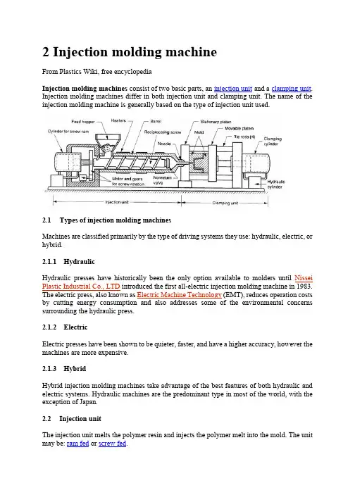
2 Injection molding machineFrom Plastics Wiki, free encyclopediaInjection molding machines consist of two basic parts, an injection unit and a clamping unit. Injection molding machines differ in both injection unit and clamping unit. The name of the injection molding machine is generally based on the type of injection unit used.2.1Types of injection molding machinesMachines are classified primarily by the type of driving systems they use: hydraulic, electric, or hybrid.2.1.1HydraulicHydraulic presses have historically been the only option available to molders until Nissei Plastic Industrial Co., LTD introduced the first all-electric injection molding machine in 1983. The electric press, also known as Electric Machine Technology (EMT), reduces operation costs by cutting energy consumption and also addresses some of the environmental concerns surrounding the hydraulic press.2.1.2ElectricElectric presses have been shown to be quieter, faster, and have a higher accuracy, however the machines are more expensive.2.1.3HybridHybrid injection molding machines take advantage of the best features of both hydraulic and electric systems. Hydraulic machines are the predominant type in most of the world, with the exception of Japan.2.2Injection unitThe injection unit melts the polymer resin and injects the polymer melt into the mold. The unit may be: ram fed or screw fed.The ram fed injection molding machine uses a hydraulically operated plunger to push the plastic through a heated region. The high viscosity melt is then spread into a thin layer by a "torpedo" to allow for better contact with the heated surfaces. The melt converges at a nozzle and is injected into the mold.Reciprocating screw A combination melting, softening, and injection unit in an injection molding machine. Another term for the injection screw. Reciprocating screws are capable of turning as they move back and forth.The reciprocating screw is used to compress, melt, and convey the material. The reciprocating screw consists of three zones (illustrated below):•feeding zone•compressing zone•metering zoneWhile the outside diameter of the screw remains constant, the depth of the flights on the reciprocating screw decreases from the feed zone to the beginning of the metering zone. These flights compress the material against the inside diameter of the barrel, which creates viscous (shear) heat. This shear heat is mainly responsible for melting the material. The heater bands outside the barrel help maintain the material in the molten state. Typically, a molding machine can have three or more heater bands or zones with different temperature settings.Injection molding reciprocating screw An extruder-type screw rotates within a cylinder, which is typically driven by a hydraulic drive mechanism. Plastic material is moved through the heated cylinder via the screw flights and the material becomes fluid. The injection nozzle is blocked by the previous shot, and this action causes the screw to pump itself backward through the cylinder. (During this step, material is plasticated and accumulated for the next shot.) When the mold clamp has locked, the injection phase takes place. At this time, the screw advances, acting as a ram. Simultaneously, the non-return valve closes off the escape passages in the screw and the screw serves as a solid plunger, moving the plastic ahead into the mold. When the injection stroke and holding cycle is completed, the screw is energized to return and the non-return valve opens, allowing plastic to flow forward from the cylinder again, thus repeating the cycle.2.2.1Feed hopperThe container holding a supply molding material to be fed to the screw. The hopper located over the barrel and the feed throat connects them.2.2.2Injection ramThe ram or screw that applies pressure on the molten plastic material to force it into the mold cavities.2.2.3Injection screwThe reciprocating-screw machine is the most common. This design uses the same barrel for melting and injection of plastic.The alternative unit involves the use of separate barrels for plasticizing and injecting the polymer. This type is called a screw-preplasticizer machine or two-stage machine. Plastic pellets are fed from a hopper into the first stage, which uses a screw to drive the polymer forward and melt it. This barrel feeds a second barrel, which uses a plunger to inject the melt into the mold. Older machines used one plunger-driven barrel to melt and inject the plastic. These machines are referred to as plunger-type injection molding machines.2.2.4BarrelBarrel is a major part that melts resins transmitted from hopper through screws and structured in a way that can heat up resins to the proper temperature. A band heater, which can control temper atures in five sections, is attached outside the barrel. Melted resins are supplied to the mold passing through barrel head, shot-off nozzle, and one-touch nozzle.2.2.5Injection cylinderHydraulic motor located inside bearing box, which is connected to injection cylinder load, rotates screw, and the melted resins are measures at the nose of screw. There are many types of injection cylinders that supply necessary power to inject resins according to the characteristics of resins and product types at appropriate speed and pressure. This model employs the double cylinder type. Injection cylinder is composed of cylinder body, piston, and piston load.2.3Clamping unitThe clamping unit holds the mold together, opens and closes it automatically, and ejects the finished part. The mechanism may be of several designs, either mechanical, hydraulic or hydromechanical.Toggle clamps - a type clamping unit include various designs. An actuator moves the crosshead forward, extending the toggle links to push the moving platen toward a closed position. At the beginning of the movement, mechanical advantage is low and speed is high; but near the end of the stroke, the reverse is true. Thus, toggle clamps provide both high speed and high force at different points in the cycle when they are desirable. They are actuated either by hydraulic cylinders or ball screws driven by electric motors. Toggle-clamp units seem most suited to relatively low-tonnage machines.Two clamping designs: (a) one possible toggle clamp design (1) open and (2) closed; and (b) hydraulic clamping (1) open and (2) closed. Tie rods used to guide movuing platens not shown.Hydraulic clamps are used on higher-tonnage injection molding machines, typically in the range 1300 to 8900 kN (150 to 1000 tons). These units are also more flexible than toggle clamps in terms of setting the tonnage at given positions during the stroke.Hydraulic Clamping System is using the direct hydraulic clamp of which the tolerance is still and below 1 %, of course, better than the toggle system. In addition, the Low Pressure Protection Device is higher than the toggle system for 10 times so that the protection for the precision and expensive mold is very good. The clamping force is focus on the central for evenly distribution that can make the adjustment of the mold flatness in automatically. Hydromechanical clamps -clamping units are designed for large tonnages, usually above 8900 kN (1000 tons); they operate by (1) using hydraulic cylinders to rapidly move the mold toward closing position, (2) locking the position by mechanical means, and (3) using high pressure hydraulic cylinders to finally close the mold and build tonnage.2.3.1Injection moldThere are two main types of injection molds: cold runner (two plate and three plate designs) and hot runner– the more common of the runnerless molds.2.3.2Injection platensSteel plates on a molding machine to which the mold is attached. Generally, two platens are used; one being stationary and the other moveable, actuated hydraulically to open and close the mold. It actually provide place to mount the mould. It contains threaded holes on which mould can be mounted using clamps.2.3.3Clamping cylinderA device that actuates the chuck through the aid of pneumatic or hydraulic energy.2.3.4Tie BarTie bars support clamping power, and 4 tie bars are located between the fixing platen and the support platen.3 Injection mouldFrom Wikipedia, the free encyclopediaMold A hollow form or cavity into which molten plastic is forced to give the shape of the required component. The term generally refers to the whole assembly of parts that make up the section of the molding equipment in which the parts are formed. Also called a tool or die. Moulds separate into at least two halves (called the core and the cavity) to permit the part to be extracted; in general the shape of a part must be such that it will not be locked into the mould. For example, sides of objects typically cannot be parallel with the direction of draw (the direction in which the core and cavity separate from each other). They are angled slightly; examination of most household objects made from plastic will show this aspect of design, known as draft. Parts that are "bucket-like" tend to shrink onto the core while cooling and, after the cavity is pulled away, are typically ejected using pins. Parts can be easily welded together after moulding to allow for a hollow part (like a water jug or doll's head) that couldn't physically be designed as one mould.More complex parts are formed using more complex moulds, which may require moveable sections, called slides, which are inserted into the mould to form particular features that cannot be formed using only a core and a cavity, but are then withdrawn to allow the part to be released. Some moulds even allow previously moulded parts to be re-inserted to allow a new plastic layer to form around the first part. This system can allow for production of fully tyred wheels.Traditionally, moulds have been very expensive to manufacture; therefore, they were usually only used in mass production where thousands of parts are being produced.Molds require: Engineering and design, special materials, machinery and highly skilled personnel to manufacture, assemble and test them.Cold-runner moldCold-runner mold Developed to provide for injection of thermoset material either directly into the cavity or through a small sub-runner and gate into the cavity. It may be compared to the hot-runner molds with the exception that the manifold section is cooled rather than heated to maintain softened but uncured material. The cavity and core plates are electrically heated to normal molding temperature and insulated from the cooler manifold section.3.1.1Types of Cold Runner MoldsThere are two major types of cold runner molds: two plate and three plate.3.1.2Two plate moldA two plate cold runner mold is the simplest type of mold. It is called a two plate mold because there is one parting plane, and the mold splits into two halves. The runner system must be located on this parting plane; thus the part can only be gated on its perimeter.3.1.3Three plate moldA three plate mold differs from a two plate in that it has two parting planes, and the mold splits into three sections every time the part is ejected. Since the mold has two parting planes, the runner system can be located on one, and the part on the other. Three plate molds are used because of their flexibility in gating location. A part can be gated virtually anywhere along its surface.3.1.4AdvantagesThe mold design is very simple, and much cheaper than a hot runner system. The mold requires less maintenance and less skill to set up and operate. Color changes are also very easy, since all of the plastic in the mold is ejected with each cycle.3.1.5DisadvantagesThe obvious disadvantage of this system is the waste plastic generated. The runners are either disposed of, or reground and reprocessed with the original material. This adds a step in the manufacturing process. Also, regrind will increase variation in the injection molding process, and could decrease the plastic's mechanical properties.3.1.6Hot runner moldHot-runner mold -injection mold in which the runners are kept hot and insulated from the chilled cavities. Plastic freezeoff occurs at gate of cavity; runners are in a separate plate so they are not, as is the case usually, ejected with the piece.Hot runner molds are two plate molds with a heated runner system inside one half of the mold.A hot runner system is divided into two parts: the manifold and the drops. The manifold has channels that convey the plastic on a single plane, parallel to the parting line, to a point abovethe cavity. The drops, situated perpendicular to the manifold, convey the plastic from the manifold to the part.3.1.7Types of Hot Runner MoldsThere are many variations of hot runner systems. Generally, hot runner systems are designated by how the plastic is heated. There are internally and externally heated drops and manifolds.3.1.8Externally heated hot runnersExternally heated hot runner channels have the lowest pressure drop of any runner system (because there is no heater obstructing flow and all the plastic is molten), and they are better for color changes none of the plastic in the runner system freezes. There are no places for material to hang up and degrade, so externally heated systems are good for thermally sensitive materials.3.1.9Internally heated hot runnersInternally heated runner systems require higher molding pressures, and color changes are very difficult. There are many places for material to hang up and degrade, so thermally sensitive materials should not be used. Internally heated drops offer better gate tip control. Internally heated systems also better separate runner heat from the mold because an insulating frozen layer is formed against the steel wall on the inside of the flow channels.3.1.10 insulated hot runnersA special type of hot runner system is an insulated runner. An insulated runner is not heated; the runner channels are extremely thick and stay molten during constant cycling. This system is very inexpensive, and offers the flexible gating advantages of other hot runners and the elimination of gates without the added cost of the manifold and drops of a heated hot runner system. Color changes are very easy. Unfortunately, these runner systems offer no control, and only commodity plastics like PP and PE can be used. If the mold stops cycling for some reason, the runner system will freeze and the mold has to be split to remove it. Insulated runners are usually used to make low tolerance parts like cups and frisbees.3.1.11 DisadvantagesHot-runner mold is much more expensive than a cold runner, it requires costly maintenance, and requires more skill to operate. Color changes with hot runner molds can be difficult, since it is virtually impossible to remove all of the plastic from an internal runner system.3.1.12 AdvantagesThey can completely eliminate runner scrap, so there are no runners to sort from the parts, and no runners to throw away or regrind and remix into the original material. Hot runners are popular in high production parts, especially with a lot of cavities.Advantages Hot Runner System Over a Cold Runner System include:•no runners to disconnect from the molded parts•no runners to remove or regrind, thus no need for process/ robotics to remove them•having no runners reduces the possibility of contamination•lower injection pressures•lower clamping pressure•consistent heat at processing temperature within the cavity•cooling time is actually shorter (as there is no need for thicker, longer-cycle runners)•shot size is reduced by runner weight•cleaner molding process (no regrinding necessary)•nozzle freeze and sprue sticking issues eliminated中文翻译注塑模具设计与制造2 注射机选自《维基百科》注射机由两个基本部分组成,注射装置和夹紧装置。
![模具设计相关专业毕业论文(外文原文+翻译)之翻译[管理资料]](https://uimg.taocdn.com/63ac390ff705cc1754270968.webp)
可行成形图在汽车覆盖件冲压工艺高效设计的应用Dae-Cheol Ko a,Seung-Hoon Cha b,Sang-Kon Lee c,Chan-Joo Lee b,Byung-Min Kim d,*a ILIC, Pusan National University, 30 Jangjeon-Dong, Kumjeong-Gu, Busan609-735, South Koreab Precision Manufacturing Systems Division, Pusan National University, 30Jangjeon-Dong, Kumjeong-Gu, Busan 609-735, South Koreac PNU-IFAM, Joint Research Center, Pusan National University, 30Jangjeon-Dong, Kumjeong-Gu, Busan 609-735, South Koread School of Mechanical Engineering, Pusan National University, 30 Jangjeon-Dong, Kumjeong-Gu, Busan 609-735, South Korea摘要:本文提出使用可行的成形图来表示无断裂和起皱的安全区域,进而有效和快速地设计冲压工艺方法。
要确定可行的成形图,有限元分析对应于正交实验设计的过程变量组合。
随后,基于成形极限图的有限元分析,确定断裂和起皱的特征值。
所有组合的特征值在整个过程中,通过人工神经网络训练进行了一系列预测。
可行的成形图从所有组合的过程变量中最终确定。
以汽车覆盖件如转动架和车轮毂的冲压工艺作为实例来验证利用成形图的进行过程设计有效性。
有限元模拟结果与实验模拟结果比较表明,利用可行的成形图来进行冲压工艺的设计是有效的并适用于实际的过程。
中英文资料对照外文翻译英文:Design and Technology of the Injection Mold1、3D solid model to replace the center layer modelThe traditional injection molding simulation software based on products of the center layer model. The user must first be thin-walled plastic products abstract into approximate plane and curved surface, the surface is called the center layer. In the center layer to generate two-dimensional planar triangular meshes, the use of these two-dimensional triangular mesh finite element method, and the final result of the analysis in the surface display. Injection product model using3D solid model, the two models are inconsistent, two modeling inevitable. But because of injection molding product shape is complex and diverse, the myriads of changes from athree-dimensional entity, abstraction of the center layer is a very difficult job, extraction process is very cumbersome and time-consuming, so the design of simulation software have fear of difficulty, it has become widely used in injection molding simulation software the bottleneck.HSCAE3D is largely accepted3D solid / surface model of the STL file format. Now the mainstream CAD/CAM system, such as UG, Pro/ENGINEER, CATIA and SolidWorks, can output high quality STL format file. That is to say, the user can use any commercial CAD/CAE systems to generate the desired products3D geometric model of the STL format file, HSCAE3D can automatically add the STL file into a finite element mesh model, through the surface matching and introduction of a new boundary conditions to ensure coordination of corresponding surface flow, based on3D solid model of analysis, and display of three-dimensional analysis results, replacing the center layer simulation technology to abstract the center layer, and then generate mesh this complicated steps, broke through system simulation application bottlenecks, greatly reducing the burden of user modeling, reduces the technical requirement of the user, the user training time from the past few weeks shorter for a fewhours. Figure 1 is based on the central layer model and surface model based on 3D solid / flow analysis simulation comparison chart.2、Finite element, finite difference, the control volume methodsInjection molding products are thin products, products in the thickness direction of size is much smaller than the other two dimensions, temperature and other physical quantities in the thickness direction of the change is very large, if the use of a simple finite element and finite difference method will cause analysis time is too long, can not meet the actual needs of mold design and manufacturing. We in the flow plane by using finite element method, the thickness direction by using finite difference method, were established and plane flow and thickness directions corresponding to the size of the grid and coupling, while the accuracy is guaranteed under the premise of the calculation speed to meet the need of engineering application, and using the control volume method is solved. The moving boundary problem in. For internal and external correspondence surface differences between products, can be divided into two parts the volume, and respectively formed the control equation, the junction of interpolation to ensure thatthe two part harmony contrast.3、Numerical analysis and artificial intelligence technologyOptimization of injection molding process parameters has been overwhelming majority of mold design staff concerns, the traditional CAE software while in computer simulation of a designated under the conditions of the injection molding conditions, but is unable to automatically optimize the technical parameters. Using CAE software personnel must be set to different process conditions were multiple CAE analysis, combined with practical experience in the program were compared between, can get satisfactory process scheme. At the same time, the parts after the CAE analysis, the system will generate a large amount of information about the project ( product, process, analyzes the results ), which often results in a variety of data form, requiring the user to have the analysis and understanding of the results of CAE analysis ability, so the traditional CAE software is a kind of passive computational tools, can provide users with intuitionistic, effective engineering conclusion, to software users demand is too high, the influence of CAE system in the larger scope of application and popularization. In view of the above, HSCAE3D software in the original CAE system based on accurate calculationfunction, the knowledge engineering technology is introduced the system development, the use of artificial intelligence is the ability of thinking and reasoning, instead of the user to complete a large number of information analysis and processing work, directly provide guiding significance for the process of conclusions and recommendations, effectively solve the CAE of the complexity of the system and the requirements of the users of the contradiction between, shortening of the CAE system and the distance between the user, the simulation software by traditional " passive" computational tools to " active" optimization system. HSCAE3D system artificial intelligence technology will be applied to the initial design, the results of the analysis of CAE interpretation and evaluation, improvement and optimization analysis of3 aspects.译文:注塑模具设计的技术1.用三维实体模型取代中心层模型传统的注塑成形仿真软件基于制品的中心层模型。
中英文对照外文翻译Heat Treatment of Die and Mould Oriented Concurrent DesignAbstract:Many disadvantages exist in the traditional die design method which belongs to serial pattern. It is well known that heat treatment is highly important to the dies. A new idea of concurrent design for heat treatment process of die and mould was developed in order to overcome the existent shortcomings of heat treatment process. Heat treatment CAD/CAE was integrated with concurrent circumstance and the relevant model was built. These investigations can remarkably improve efficiency, reduce cost and ensure quality of R and D for products.Key words :die design; heat treatment; mouldong desires for precision,service life,development period and cost,modern die and mould should be designed and manufactured perfectly.Therefore more and more advanced technologies and innovations have been applied,for example,concurrent engineering,agile manufacturing virtual manufacturing,collaborative design,etc.Heat treatment of die and mould is as important as design,manufacture and assembly because it has a vital effect on manufacture,assembly and service life.Design and manufacture of die and mould have progressed rapidly,but heat treatment lagged seriously behind them.As die and mould industry develops,heat treatment must ensure die and mould there are goodstate of manufacture,assembly and wear—resistant properties by request. Impertinent heat treatment can influence die and mould manufacturing such as over—hard and—soft and assembly.Traditionally the heat treatment process was made out according to the methods and properties brought forward by designer.This could make the designers of die and mould and heat treatment diverge from each other,for the designers of die and mould could not fully realize heat treatment process and materials properties,and contrarily the designers rarely understood the service environment and designing thought. These divergences will impact the progress of die and mould to a great extent. Accordingly,if the process design of heat treatment is considered in the early designing stage,the aims of shortening development period,reducing cost and stabilizing quality will be achieved and the sublimation of development pattern from serial to concurrent will be realized.Concurrent engineering takes computer integration system as a carrier,at the very start subsequent each stage and factors have been considered such as manufacturing,heat treating,properties and so forth in order to avoid the error.The concurrent pattern has dismissed the defect of serial pattern,which bring about a revolution against serial pattern.In the present work.the heat treatment was integrated into the concurrent circumstance of the die and mould development,and the systemic and profound research was performed.1 Heat Treatment Under Concurrent CircumstanceThe concurrent pattern differs ultimately from the serial pattern(see Fig.1).With regard to serial pattern,the designers mostly consider the structure and function of die and mould,yet hardly consider the consequent process,so that the former mistakes are easily spread backwards.Meanwhile,the design department rarely communicates with the assembling,cost accounting and sales departments.These problems certainly will influence the development progress of die and mould and the market foreground.Whereas in the concurrent pattern,the relations among departments are close,the related departments all take part in the development progress of die and mould and have close intercommunion with purchasers.This is propitious to eliminationof the conflicts between departments,increase the efficiency and reduce the cost.Heat treatment process in the concurrent circumstance is made out not after blueprint and workpiece taken but during die an d mould designing.In this way,it is favorable to optimizing the heat treatment process and making full use of the potential of the materials.2 Integration of Heat Treatment CAD/CAE for Die and MouldIt can be seen from Fig.2 that the process design and simulation of heat treatment are the core of integration frame.After information input via product design module and heat treatment process generated via heat treatment CAD and heat treatment CAE module will automatically divide the mesh for parts drawing,simulation temperature field microstructure analysis after heat—treatment and the defect of possible emerging (such as overheat,over burning),and then the heat treatment process is judged if the optimization is made according to the result reappeared by stereoscopic visiontechnology.Moreover tool and clamping apparatus CAD and CAM are integrated into this system.The concurrent engineering based integration frame can share information with other branch.That makes for optimizing the heat treatment process and ensuring the process sound.2.1 3-D model and stereoscopic vision technology for heat treatmentThe problems about materials,structure and size for die and mould can be discovered as soon as possible by 3-D model for heat treatment based on the shape of die and mould.Modeling heating condition and phase transformation condition for die and mould during heat treatment are workable,because it has been broken through for the calculation of phase transformation thermodynamics,phase transformation kinetics,phase stress,thermal stress,heat transfer,hydrokinetics etc.For example,3-D heat —conducting algorithm models for local heating complicated impression andasymmetric die and mould,and M ARC software models for microstructure transformation was used.Computer can present the informations of temperature,microstructure and stress at arbitrary time and display the entire transformation procedure in the form of 3-D by coupling temperature field,microstructure field and stress field.If the property can be coupled,various partial properties can be predicted by computer.2.2 Heat treatment process designDue to the special requests for strength,hardness,surface roughness and distortion during heat treatment for die and mould,the parameters including quenching medium type,quenching temperature and tempering temperature and time,must be properly selected,and whether using surface quenching or chemical heat treatment the parameters must be rightly determined.It is difficult to determine the parameters by computer fully.Since computer technology develops quickly in recent decades,the difficulty with large—scale calculation has been overcome.By simulating and weighing the property,the cost and the required period after heat treatment.it is not difficult to optimize the heat treatment process.2.3 Data base for heat treatmentA heat treatment database is described in Fig.3.The database is the foundation of making out heat treatment process.Generally,heat treatment database is divided into materials database and process database.It is an inexorable trend to predict the property by materials and process.Although it is difficult to establish a property database,it is necessary to establish the database by a series of tests.The materials database includes steel grades,chemical compositions,properties and home and abroad grades parallel tables.The process database includes heat treatment criterions,classes,heat preservation time and cooling velocity.Based on the database,heat treatment process can be created by inferring from rules.2.4 Tool and equipment for heat treatmentAfter heat treatment process is determined,tool and equipment CAD/CAE system transfers the information about design and manufacture to the numerical control device.Through rapid tooling prototype,the reliability of tool and the clamping apparatus can be judged.The whole procedure is transferred by network,in which there is no man—made interference.3 Key Technique3.1 Coupling of temperature,microstructure,stress and propertyHeat treatment procedure is a procedure of temperature-microstructure—stress interaction.The three factors can all influence the property (see Fig.4).During heating and cooling,hot stress and transformation will come into being when microstructure changes.Transformation temperature-microstructure and temperature—microstructure—and stress-property interact on each other.Research on the interaction of the four factors has been greatly developed,but the universal mathematic model has not been built.Many models fit the test nicely,but they cannot be put into practice.Difficulties with most of models are solved in analytic solution,and numerical method is employed so that the inaccuracy of calculation exists.Even so,comparing experience method with qualitative analysis,heat treatment simulation by computer makes great progress.3.2 Establishment and integration of modelsThe development procedure for die and mould involves design,manufacture,heat treatment,assembly,maintenance and so on.They should have own database and mode1.They are in series with each other by the entity—relation model.Through establishing and employing dynamic inference mechanism ,the aim of optimizing design can be achieved.The relation between product model and other models was built.The product model will change in case the cell model changes.In fact,it belongs to the relation of data with die and mould.After heat treatment model is integrated into the system,it is no more an isolated unit but a member which is close to other models in the system.After searching,calculating and reasoning from the heat treatment database,procedure for heat treatment,which is restricted by geometric model,manufacture model for die and mould and by cost and property,is obtained.If the restriction is disobeyed,the system will send out the interpretative warning.All design cells are connected by communication network.3.3 Management and harmony among membersThe complexity of die and mould requires closely cooperating among item groups.Because each member is short of global consideration for die and mould development,they need to be managed and harmonized.Firstly,each item group should define its own control condition and resource requested,and learn of the request of up-and-down working procedure in order to avoid conflict.Secondly,development plan should be made out and monitor mechanism should be established.The obstruction can be duly excluded in case the development is hindered.Agile management and harmony redound to communicating information,increasing efficiency,and reducing redundancy.Meanwhile it is beneficial for exciting creativity,clearing conflict and making the best of resource.4 Conclusions(1) Heat treatment CAD/CAE has been integrated into concurrent design for die and mould and heat treatment is graphed,which can increase efficiency,easily discover problems and clear conflicts.(2) Die and mould development is performed on the same platform.When the heat treatment process is made out,designers can obtain correlative information and transfer self-information to other design departments on the platform.(3) Making out correct development schedule and adjusting it in time can enormously shorten the development period and reduce cost.References:[1] ZHOU Xiong-hui,PENG Ying-hong.The Theory and Technique of Modern Die and Mould Design and Manufacture[M].Shanghai:Shanghai Jiaotong University Press 2000(in Chinese).[2] Kang M,Park& Computer Integrated Mold Manufacturing[J].Int J Computer Integrated Manufacturing,1995,5:229-239.[3] Yau H T,Meno C H.Concurrent Process Planning for Finishing Milling and Dimensional Inspection of Sculptured Surface in Die and Mould Manufacturing[J].Int J Product Research,1993,31(11):2709—2725.[4] LI Xiang,ZHOU Xiong-hui,RUAN Xue-yu.Application of Injection Mold Collaborative Manufacturing System [J].JournaI of Shanghai Jiaotong University,2000,35(4):1391-1394.[5] Kuzman K,Nardin B,Kovae M ,et a1.The Integration of Rapid Prototyping and CAE in Mould Manufacturing [J].J Materials Processing Technology,2001,111:279—285.[6] LI Xiong,ZHANG Hong—bing,RUAN Xue-yu,et a1.Heat Treatment Process Design Oriented Based on Concurrent Engineering[J].Journal of Iron and Steel Research,2002,14(4):26—29.文献出处:LI Xiong,ZHANG Hong-bing,RUAN Xue—yu,LUO Zhong—hua,ZHANG Yan.Heat Treatment of Die and Mould Oriented Concurrent Design[J].Journal of Iron and Steel Research,2006,13(1):40-43,74模具热处理及其导向平行设计摘要:在一系列方式中,传统模具设计方法存在许多缺点。
外文原文:Gas-Assisted Injection MoldingInjection molding is a very popular operation for production of commercial plastic parts with its sophisticated control and superior surface details. However, it has limitations, such as long cycle time for parts with thick sections due to slow cooling. Also packing of thick sections can produce sink marks on the part surface. Large thin parts can have warpage because the residual stress and strain induced during filling and packing. Thus traditional injection molding can be modified to solve these kinds of problems, also to improve the quality of the part and lower the cost of production.Currently, gas-assisted injection molding is in use and being developed worldwide. In the US, the process is known as Gas-Assisted Injection Molding (GAIM); it is also called Gas Injection Technique (GIT) in Europe (see Fig.4.3.1). This process is developed for the production of hollow plastic parts with separate internal channels. It is unique because it combines the advantages of conventional injection molding and blow molding while differing from both. GAIM offers a cost effective means of producing large, smooth surfaced and rigid parts using lower clamping pressure with little or no finishing. By introducing the gas before complete filling, numerous problems such as warpage, sink marks, and high filling pressure are mostly overcome. Moreover, the process gives great benefits in terms of higher stiffness-to-weight ratio than the solid parts with the same overall dimensions due to the elimination of material placed inefficiently near the neutral axis of the cross section, thus increasing the freedom of part design.In comparison with conventional injection molding, the gas-assisted process is more critical in terms of process control, especially for multi-cavity applications. The quality of the part is determined by both tool and process variables such as degree of under-fill, gas injection conditions, and mold temperature, thus indicating the importance of process control. The process is attracting many molders due to the demand for highly automated production of gas-assisted injection molded parts.The gas-assisted injection molding process is the most rapidly growing fieldwith considerable work going on in the field of controls and the process development. Research interest is drawn towards the development of new gas injection units, the study of the process variable, the efficiency of the production process, and advantages offered by the new process. Many different companies are offering gas injection-molding units with the various options, which are mainly pressure controlled or volume controlled processes.In gas injection molding, the mold is partially filled with molten thermoplastic, and an inert gas, usually nitrogen, is injected into the plastic. Gas is injected into the molten thermoplastic material using either of two procedures. In one method, a measured volume of gas is pressurized in a container. A valve is opened to allow the gas to flow into the polymer, and a piston is activated to force all gas from the container into the mold. As the gas expands in the mold, its pressure drops. A second method holds gas pressure, rather than gas volume, constant. The gas rapidly travels down the thickest-and therefore the hottest-section of the part, advancing the melt front and filling and packing the mold. Additional plastic volume may be displaced by the pressurized gas as the material shrinks. After the plastic cools, the gas is allowed to escape, leaving a molded plastic part containing internal voids.The standard GAIM process can be divided into four partial steps. The first step is a stage of melts injection [Fig.4.3.2 (a)]. The cavity is partially filled with a defined amount of melt. The required volume is empirically determined by performing filling studies in order to avoid blowing the gas through at the flow front and to ensure an ideal blowhole volume. Typically the polymer fills thecavity between 75%~95% before the meltand gas transition.The gas inlet phase is the second stage,which is shown in Fig. 4. 3. 2(b). Gas maybe added at any point in time either duringor shortly after melts injection. The gas canenter only if the gas pressure exceeds themelt pressured. In the interior of the moldedpart, the gas expels the melt from the plasticnucleus until the remainder of the cavity iscompletely filled. Gas injection pressuresrange from 0.5~30Mpa (70~4500psi).At the gas holding pressure phase, [Fig.4.3.2(c)] the gas continues to push thepolymer melt into the extremities of thecavity of the molded article acts as a holdingpressure to compensate for path of leastresistance as it pushes through the polymer.The final stage is a gas return for recycling or a gas release to atmosphere [Fig.4. 3. 2 (d)]. After the gas holding phase, the gas pressure in the molded article is released to the outside by suitable gas return and/ or by pressure release.A. Advantages of the GAIM processGas injection provides a solution to a number of problemsthat occurs in conventional injection molding.(1) Reducing stress and warpageWith gas, the pressure is equal everywhere throughout the continuous network of hollow channels. When designed properly, these provide an internal runner system within the part, enabling the applied pressure, and therefore the internal stress gradients, to be reduced markedly. This reduces a part’s tendency to warp.(2) Elimination of sink marksSink marks resulting from ribs or bosses on the backside of a part have long been a problem. These surface marks result from the volume contraction of the melt during cooling. Sink marks can be minimized or eliminated if a hollow gas channel can be directed between the front surface of the part and the backside detail. With gas injection, the base of the rib made somewhat thicker to help direct the gas channel. With a gas channel at the base of a rib, material shrinks are away from the inside surface of the channel as the molded part cools because the material is the hottest at the center. Therefore, no sink mark occurs on the outside surface as the part shrinks during cooling.(3) Smooth surfaceUnlike structural foam, gas injection permits lighter weight and saves material ina structurally rigid part. With gas holding, a good surface quality can be achieved.(4) Reduced clamp tonnageIn conventional injection, the highest pressure occurs during the packing phase. The maximum injection pressure is significantly lower in GAIM and a controlled gas pressure through a network of hollow channels is used to fill out the mold. This means that clamp tonnage requirements can be reduced by as much as 90%.(5) Elimination of external runnersOne of the best features of gas injection is that flow runners can be built right into the part. Frequently, all external runners (both hot and cold) can be eliminated, even on a larger and complex part. These benefits include the reduced tooling costs, the lower quantities of regrind from runners, and the improvement of temperature control over the plastic melt. Often the internal runners can improve the flow pattern in the mold and eliminate or control knit-line location resulting from multiple injections from multiple injection gates. In addition to serving as flow channels, the ribs and thick sections can provide structural rigidity when required.(6)Permitting different wall thicknessA constant wall thickness is maintained in the plastic parts. With gas injection, this design rule is flexible. Different wall thicknesses are possible if gas channels are designed into the part at the transition points. This permits uniform materialflows in the mold and avoids the high stresses and warpage that normally result from this sort of geometry.(7) Cycle time ReductionCompared with structural foam, gas-injection parts do not have the same inherent insulating characteristics, so that cycle times are faster-reportedly even faster than would be conventional injection of the same part with no hollow sections.(8) Resin savingGas assist plays a direct role in part-weight saving in the conversion of current tools. The main factor in reducing weight is that the part cavity is never completely filled. Another major contributor to resin saving is scrap reduction. With proper tool design, gas assisted allows scrap-free startups and production runs.B. Disadvantages of the GAIM processAll processes have their disadvantages, but those of GAIM and GAIMIC (Gas-assisted injection molding with internal-water cooling) appear relatively minor compared with their significant advantages.(1) Large hollow sectionsGIAM is not well suited for thin-walled hollow parts such as bottles or tanks. However, the thin-wall part has also tried out for some specific applications.(2) Vent holeThe gas must be vented prior to opening the mold, leaving a hole somewhere on the part. Normally this can be placed in a non-visible location, but if appearance or function is affected or secondary operations are required, it may be necessary to seal the hole.(3) Mold temperature controlSince wall thickness along the gas flow channel is a function of cooling rate, consistent wall thickness requires precise mold temperature control.(4) Surface blushThe gas channel may leave surface blush, which arises from differences in surface gloss leaves. The tendency for blush is a function of processing conditionsand types of plastics.(5) Unique designThe unique part design and mold design required in most cases to fully utilize that GAIM might be considered by some to be a disadvantage. The gas part design takes a relatively longer time than with the conventional injection molding process.(6)Extra cost of controllerIn order to control the gas injection, the process requires extra equipment. Gas-assisted injection molding with internal cooling requires a system for controlling the gas and the water, an expense not required with traditional injection molding.C. Types of process defects in the GAIMFingering, gas bubbles, hesitation lines, burning of resin, witness line cold slug, and gas blowout are typical defects normally encountered in GAIM.Fingering, or gas permeation, is a common problem encountered in GAIM. In fingering, gas escapes from the gas channel and migrates into undesired areas of the part. Severe gas fingering can result in significant reduction n in part stiffness, impact strength and reliabitity of the final molded part. During the gas holding phase, the transitional region between the gas channel and the flat area is possible for fingers to form within the flat area. In this case, the main cause of the fingering effect is the higher its shrinkage potential, and hence the greater danger of the fingering effect. In order to largely exclude the fingering effect through design, it is necessary to implement the following criteria: a basic wall thickness of 4mm or greater should be avoided for flat areas, a material with favorable solidification behavior should be selected, and the lowest possible gas pressure should be applied.Gas bubbles are caused by fingering. When fingering occurs, gas sometimes gets trapped in the thin-wall sections of the part where the gas is unable to fully vent. These trapped gases can cause bubbles that will still be in the gas core after the mold is opened.Hesitation lines appear on the surface of a part produced by GAIM when theshort shot of resin stops in the cavity, then starts moving again as the gas completes the fill.Burning of the resin can appear on either the outer surface of the part or within the gas channel itself. Burning of the part surface can be caused by gas pressure that is too high or by insufficient venting of the mold. Burning, the resin within the hollow sections of the part is also possible. Burning within the gas channel can cause gas injection pins to become plugged.On thin-walled parts molded in certain resins, a witness line, or gloss-level change, can occur over the gas channel. Excessive gas pressure can also cause witness lines over gas channels.When gas is injected through the molding machine nozzle, cold slugs of resin may occur on the part surface. A cold slug is caused when a small amount of unmelted resin is injected into the part.Gas blowout occurs when there is not enough resin in the cavity to hold the gas inside the part. If the part is short, gas will migrate to the non-filled area of the cavity and blow through. When blowout occurs, the part will sometimes look like a short shot.Most cases of defects are produced by the interface of the gas and the melt. These problems can be overcome by internal water-cooling between the interface of the gas and the melt.中文译文:气辅注射成型注射成型是一种很普通的生产方法,用于加工那种生产时难以控制和有复杂表面的商业塑件。
附录1 英文原文Mould Design and ManufacturingCAD and CAM are widely applied in mould design and mould making.CAD allows you to draw a model on screen ,then view it from every angle using 3-D animating and ,finally ,to test it by introducing various parameters into the digital simulation models (pressure ,temperature ,impact ,etc .)CAM ,on the other hand ,allows you to control the manufacturing quality .The advantages of these computer technologies are legion ;shorter design times (modifications can be made at the speed of the computer ).lower cost ,faster manufacturing ,etc .This new approach also allows shorter production runs ,and to make last-minute changes to the mould for a particular part.Finally ,also ,these new processes can be use to make complex parts .Computer-Aided Design (CAD) of MouldTraditionally, the creation of drawings of mould tools has been a time-consuming task that is not part of the creative process. Drawings are an organizational necessity rather than a desired part of the process .Computer-Aided Design (CAD) means using the computer and peripheral devices to simplify and enhance the design process .CAD systems offer an efficient means of design ,and can be use to create inspection equipment .CAD data also can play a critical role in selecting process sequence .A CAD system consists of three basic components ;hardware ,software,User ,The hardware components of a typical CAD system include a processor ,a system display,a keyboard, a digitizer, and a plotter. The software component of a CAD system consists of the programs which allow it to perform design and drafting functions.The user is the tool designer who uses the hardware and software to perform the design process.Based on he 3-D data of the product, the core and cavity have to be designedsrally the designer begins with a preliminary part design ,which means the work around the core and cavity could change .Modern CAD systems can support this with calculating a spot line for a defined draft direction ,splitting the part in the core and cavity side and generating the run-off or shut-off true faces .After the calculation of the optimal draft of the part, the position and direction of the cavity, slides and inserts have to be defined .Then,in the conceptual stage, the positions and the geometry of the mould –such as slides, ejection system, etc. –are roughly defined. With this information, the size and thickness of the plates can be defined and the corresponding standard mould that comes nearest to the requirements is chosen and changed accordingly –by adjusting the constraints and paramenter so that any number of plates with any size can be use in the mould. Detailing the functional components and adding the standard any size can be used in the mould. Detailing the functional compontnts and adding the standard components complete the mould.This all happens in 3D .Moreover ,the mould system provide functions for the checking, modifying and detailing of the part .Already in this early stage ,drawings and bill of materials can be created automatically.Through the use of 3D and the intelligence of the mould system, typical 2D mistakes –such as a collision between cooling and components/cavities or the wrong position of a hole –can be eliminated at the beginning. At any stage a bill of materials and drawings can be created-allowing the material to be ordered on time and always having an actual document to discuss with the customer or a bid for a mould base manufacturer .The use of a special 3D mould design system can shorten development cycles, improve mould quality ,enhance teamwork and free the designer from tedious routine work .The development cycles can be shortened only when organization and personnel measures are taken. The part design, mould design, electric design and mould manufacturing departments have to consistently work together in a tight relationship .Computer-Aided Manufacturing (CAM ) of MouldOne way to reduce the cost of manufacturing and reduce lead-time is by settingup a manufacturing system that uses equipment and personnel to their fullest potential .the foundation for this type of manufacturing system as the use of CAD data to help in madding key process decisions that ultimately improve machining precision and reduce non-productive time .This is called as computer-aided manufacturing (CAM).The objective of CAM is to produce, if possible ,sections of a mould without intermediate steps by initiating machining operations from the computer workstation .With a good CAM system, automation does not just occur within individual features. Atuomation of machining processes also occurs between all of the features make up a part, resulting in tool-path optimization. As you create features, the CAM system constructs a process plan for you .Operations are ordered based on a system analysis to reduce tool changes and the number of tools used .On the CAM sidethe trend is toward newer technologies and processes such as micro milling to support the manufacturing of high-precision injection moulds with complex 3D structures and high surface qualities. CAM software will continue to add to the depth and breadth of the machining intelligence inherent in the software until the CNC programming process becomes completely automatic. This is especially true for advanced multifunction machine tools becomes completely automatic This is especially true for advanced multifunction machine tools that require a more flexible combination of machining operations .CAM software will continue to automate more and more of manufacturing redundant work that can be handled faster and more accratrly by computers, while retaining the control that machinists need.With the emphasis in the mould making industry today on producing moulds in the most efficient manner while still maintaining quality, mold makers need to keep up with the latest software technologies-packages that will allow them to program and cut complex moulds quickly so that mould production time can be reduced .In a nutshell, the industry is moving toward improving the quality of data exchange between CAD and CAM as well as CAM to the CNC ,and CAM software is becoming more “intelligent” as it relates to machining processes-resulting in reduction in both cycle time and overall machining time .Five-axis machining also is emerging as a “must-have” on the shop floor-especially when dealing with deepcavities. And with the introduction of electronic date processing (EDP) into the mould making industry, new opportunities have arisen in mould-making to shorten production time, improve cost efficiencies and achieve higher quality.The Science of mold MakingThe traditional method of making large automotive sheet metal dies by model building and tracing has been replaced by CAD/CAM terminals that convert mathematical descriptions of body panel shapes into cutter paths.Teledyne Specialty Equipment’s Efficient Die and Mold facility is one of the companies on the leading edge of this transformation.Only a few years ago,the huge steel dies requited for stamping sheet metal auto body panels were built by starting with a detailed blueprint and an accurate full-scale master model of the part. The model was the source from which the tooling was designed and produced.The dies,machined from castings,were prepared from patterns made by the die manutacturers or something supplied by the car maker.Secondary scale models called”tracing aids” were made from the master model for use on duplicating machines with tracers.These machines traced the contour of the scale model with a stylus,and the information derived guided a milling cutter that carved away unwanted metal to duplicate the shape of the model in the steel casting.All that is changing.Now,companies such as Teledyne Specialty Equipment’s Efficient Die and Mold operation in Independence,OH,work from CAD data supplied by customers to generate cutter paths for milling machines,which then automatically cut the sheetmetal dies and SMC compression molds.Although the process is used to make both surfaces of the tool, the draw die still requires a tryout and “benching” process.Also, the CAD data typically encompasses just the orimary surface of the tool,and some machined surfaces, such as the hosts and wear pads, are typically part of the math surface.William Nordby,vice president and business manager of dies and molds at Teledyne,says that “although no one has taken CAD/CAM to the point of building theentire tool,it will eventually go in that direction because the “big thrdd”want to compress cycle times and are trying to cut the amount of time that it takes to build the tooling.Tryout, because of the lack of development on the design end,is still a very time-consuming art, and very much a trial-and-error process.”No More Models and Tracing AidsThe results to this new technology are impressive. For example, tolerances are tighter and hand finishing of the primary die surface with grinders has all but been eliminated. The big difference, says Gary Kral, Teledyne’s director of engineering, is that the dimensional control has radically improved. Conventional methods of making plaster molds just couldn’t hold tolerances because of day-to-day temperature and humidity variations.”For SMC molds the process is so accurate , and because there is no spring back like there is when stamping sheet metal, tryouts are not always required.SMC molds are approved by customers on a regulate basis without ever running a part .Such approvals are possible because of Teledyne’s ability to check the tool surface based on mathematical analysis and guarantee that it is made exactly to the original design data. Because manual trials and processes have been eliminated, Teledyne has been able to consider foreign markets.” The ability to get a tool approved based on the mathe gives us the opportunity to compete in places we wouldn’t have otherwise,” says Nordby. According to Jim Church, systems manager at Teledyne, the company used to have lots of pattern makers ,and still has one model maker.”But 99.9 percent of the company’s work now is from CAD data. Instead of model makers, engineers work in front of computer monitors.”He says that improvements in tool quality and reduction in manufacturing time are significant. Capabilities of the process were demonstrated by producing two identical tools. One was cut using conventional patterns and tracing mills, and the other tool was machined using computer generated cutting paths. Although machining time was 14 percent greater with the CAM-generated path, polishing hours were cut by 33 percent. In all ,manufacturing time decreased 16.5 percent and tool quality increased 12 percent.Teledyne’s CAD/CAM system uses state-of-the-art software that allows engineers to design dies and molds, develop CNC milling cutter paths and incorporate design changes easily. The system supports full-color, shaded three-dimensional modeling on its monitors to enhance its design and analysis capabilities. The CAD/CAM system also provides finite element analysis that can be used to improve the quality of castings , and to analyze the thermal properties of molds. Inputs virtually from any customer database can be used either directly or through translation.CMM Is CriticalTeledyne’s coordinate measuring machine(CMM),says’Church,”is what has made a difference in terms of being able to move from the traditional manual processes of mold and die making to the automated system that Teledyne uses today.”The CMM precisely locates any point in a volume of space measuring 128 in, by 80 in, by 54 in, to an accuracy of 0.0007 in. It can measure parts, dies and molds weighing up to 40 tons. For maximum accuracy,the machine is housed in an environmentally isolated room where temperature is maintained within 2 deg.F of optimum. To isolate the CMM from vibration, it is mounted on a 100-ton concrete block supported on art cushions.According to Nordby, the CMM is used not only as a quality tool, but also as a process checking tool. “ As a tool goes through the shop, it is checked several times to validate the previous operation that was performed.”For example, after the initial surface of a mold is machined and before any finish work is done, it is run through the CMM for a complete data check to determine how close the surface is to the required geometry.The mold is checked with a very dense pattern based on flow lines of the part. Each mold is checked twice, once before benching and again after benching. Measurements taken from both halves of the mold are used to calculate theoretical stock thickness at full closure of the mold to verify its accuracy with the CAD design data.Sheet Metal Dies Are Different“Sheet metal is a different ballgame,” says Nordby, “because you have the issue of material springback and the way the metal forms in the die. What happens in the sheet metal is that you do the same kinds of things for the male punch as you would with SMC molds and you ensure that it is 100 percent to math data. But due to machined surface tolerance variations, the female half becomes the working side of the tool. And there is still a lot of development required after the tool goes into the press. The math generated surfaces apply primarily to the part surface of the tool.”EMS Tracks the Manufacturing ProcessTeledyne’s business operations also are computerized and carried over a network consisting of a V AX server and PC terminals. IMS (Effective Management Systems) software tracks orders, jobs in progress, location of arts, purchasing, receiving, and is now being upgraded to include accounting functions.Overall capabilities of the EMS system include bill-of-material planning and control, inventory management, standard costing, material history, master production scheduling, material requirements planning, customer order processing, booking and sales history, accounts receivable, labor history, shop floor control, scheduling, estimating, standard routings, capacity requirements planning, job costing, purchasing and receiving, requisitions, purchasing and receiving, requisitions, purchasing history and accounts payable.According to Frank Zugaro, Teledyne’s scheduling manager, the EMS software was chosen because of its capabilities in scheduling time and resources in a job shop environment. All information about a job is entered into inventory management to generate a structured bill of material. Then routes are attached to it and work orders are generated.The system provides daily updates of data by operator hour as well as a material log by shop order and word order. Since the database is interactive, tracking of materials received and their flow through the build procedure can be documented and cost data sent to accounting and purchasing.Gary Kral, Teledyne’s director of engineering, says that EMS is really a tracking device, and one of the systems greatest benefits is that it provides a documentedrecord of everything involving a job and eliminates problems that could arise from verbal instructions and promises. Kral says that as the system is used more, they are finding that it pays to document more things to make it part of the permanent record. It helps keep them focused.2 中文翻译模具设计与制造CAD和CAM广泛用于模具的设计和制造中。
Injection MoldingThe basic concept of injection molding revolves around the ability of a thermoplastic material to be softened by heat and to harden when cooled .In most operations ,granular material (the plastic resin) is fed into one end of the cylinder (usually through a feeding device known as a hopper ),heated, and softened(plasticized or plasticized),forced out the other end of the cylinder, while it is still in the form of a melt, through a nozzle into a relatively cool mold held closed under pressure.Here,the melt cools and hardens until fully set-up. The mold is then opened, the piece ejected, and the sequence repeated.Thus, the significant elements of an injection molding machine become: 1) the way in which the melt is plasticized (softened) and forced into the mold (called the injection unit);2) the system for opening the mold and closing it under pressure (called the clamping unit);3) the type of mold used;4) the machine controls.The part of an injection-molding machine, which converts a plastic material from a sold phase to homogeneous seni-liguid phase by raising its temperature .This unit maintains the material at a present temperature and force it through the injection unit nozzle into a mold .The plunger is a combination of the injection and plasticizing device in which a heating chamber is mounted between the plunger and mold. This chamber heats the plastic material by conduction .The plunger, on each stroke; pushes unbelted plastic material into the chamber, which in turn forces plastic melt at the front of the chamber out through the nozzleThe part of an injection molding machine in which the mold is mounted, and which provides the motion and force to open and close the mold and to hold the mold close with force during injection .This unit can also provide other features necessary for the effective functioning of the molding operation .Movingplate is the member of the clamping unit, which is moved toward a stationary member. the moving section of the mold is bolted to this moving plate .This member usually includes the ejector holes and mold mounting pattern of blot holes or “T” slots .Stationary plate is the fixed member of the clamping unit on which the stationary section of the mold is bolted .This member usually includes a mold-mounting pattern of boles or “T” slots. Tie rods are member of the clamping force actuating mechanism that serve as the tension member of the clamp when it is holding the mold closed. They also serve as a gutted member for the movable plate .Ejector is a provision in the clamping unit that actuates a mechanism within the mold to eject the molded part(s) from the mold .The ejection actuating force may be applied hydraulically or pneumatically by a cylinder(s) attached to the moving plate, or mechanically by the opening stroke of the moving plate.Methods of melting and injecting the plastic differ from one machine to another and are constantly being implored .conventional machines use a cylinder and piston to do both jobs .This method simplifies machine construction but makes control of injection temperatures and pressures an inherently difficult problem .Other machines use a plasticizing extruder to melt the plastic and piston to inject it while some hare been designed to use a screw for both jobs :Nowadays, sixty percent of the machines use a reciprocating screw,35% a plunger (concentrated in the smaller machine size),and 5%a screw pot.Many of the problems connected with in ejection molding arise because the densities of polymers change so markedly with temperature and pressure. thigh temperatures, the density of a polymer is considerably cower than at room temperature, provided the pressure is the same.Therefore,if molds were filled at atmospheric pressure, “shrinkage” would make the molding deviate form the shape of the mold.To compensate for this poor effect, molds are filled at high pressure. The pressure compresses the polymer and allows more materials to flow into the mold, shrinkage is reduced and better quality moldings are produced.Cludes a mold-mounting pattern of bolt holes or “T” slots. Tie rods are members of the clamping force actuating mechanism that serve as the tension members of clamp when it is holding the mold closed. Ejector is a provision in the calming unit that actuates a mechanism within the mold to eject the molded part(s) form the mold. The ejection actuating force may be applied hydraulically or pneumatically by a cylinder(s) attached to the moving plate, or mechanically by the opening stroke of the moving plate.The function of a mold is twofold: imparting the desired shape to the plasticized polymer and cooling the injection molded part. It is basically made up of two sets of components: the cavities and cores and the base in which the cavities and cores are mounted. The mold ,which contains one or more cavities, consists of two basic parts :(1) a stationary molds half one the side where the plastic is injected,(2)Moving half on the closing or ejector side of the machine. The separation between the two mold halves is called the parting line. In some cases the cavity is partly in the stationary and partly in the moving section. The size and weight of the molded parts limit the number of cavities in the mold and also determine the machinery capacity required. The mold components and their functions are as following:(1)Mold Base-Hold cavity (cavities) in fixed, correctposition relative to machine nozzle.(2)Guide Pins-Maintain Proper alignment of entry into moldinterior.(3)Spree Bushing (spree)-Provide means of entry into moldinterior.(4)Runners-Conroy molten plastic from spree to cavities.(5)Gates-Control flow into cavities.(6)Cavity (female) and Force (male)-Control the size,shape and surface of mold article.(7)Water Channels-Control the temperature of mold surfacesto chill plastic to rigid state.(8)Side (actuated by came, gears or hydrauliccylinders)-Form side holes, slots, undercuts and threaded sections.(9)Vent-Allow the escape of trapped air and gas.(10)Ejector Mechanism (pins, blades, stripper plate)-Ejectrigid molded article form cavity or force.(11)Ejector Return Pins-Return ejector pins to retractedposition as mold closes for next cycle.The distance between the outer cavities and the primary spree must not be so long that the molten plastic loses too much heat in the runner to fill the outer cavities properly. The cavities should be so arranged around the primary spree that each receives its full and equal share of the total pressure available, through its own runner system (or the so-called balanced runner system).The requires the shortest possible distance between cavities and primary sprue, equal runner and gate dimension, and uniform culling.注射成型注射成型的基本概念是使热塑性材料在受热时熔融,冷却时硬化,在大部分加工中,粒状材料(即塑料树脂)从料筒的一端(通常通过一个叫做“料斗”的进料装置)送进,受热并熔融(即塑化或增塑),然后当材料还是溶体时,通过一个喷嘴从料筒的另一端挤到一个相对较冷的压和封闭的模子里。
外文资料翻译资料来源:《模具设计与制造专业英语》文章名:Chapter 3 Casting Dies书刊名:《English for Die & Mould Design and Manufacturing》作者:刘建雄王家惠廖丕博主编出版社:北京大学出版社,2002章节:Chapter 3 Casting Dies页码:P51~P60文章译名:铸造模具Chapter 3 Casting Dies3.1CastingThe first castings were made during the period 4000~3000 B.C., using stone and metal molds for casting copper. Various casting processes have been developed over a long period of time, each with its own characteristics and applications, to meet specific engineering and service requirements. Many parts and components are made by casting, including cameras, carburetors, engine blocks, crankshafts, automotive components, agricultural and railroad equipment, pipes and plumbing fixtures, power tools, gun barrels, frying pans, and very large components for hydraulic turbines.Casting can be done in several ways. The two major ones are sand casting, in which the molds used are disposable after each cycle, and die casting, or permanent molding, in which the same metallic die is used thousands or even millions of times. Both types of molds have three common features. They both have a “plumbing” system to channel molten alloy into the mold cavity. These channels are called sprues, runners, and gates (Fig. 3-1). Molds may be modified by cores which form holes and undercuts or inserts that become an integral part of the casting. Inserts strengthen and reduce friction, and they may be more machinable than the surrounding metal. For example, a steel shaft when properly inserted into a die cavity results in an assembled aluminum step gear after the shot.After pouring or injection, the resulting castings require subsequent operations such trim-ming, inspection, grinding, and repairs to a greater or lesser extent prior to shipping. Premium-quality castings from alloys of aluminum or steel require x-ray soundness that will be acceptable by the customer.Certain special casting processes are precision-investment casting, low-pressure casting, and centrifugal casting.3.2Sand CastingThe traditional method of casting metals is in sand molds and has been used for millennia. Simply stated, sand casting consists of (a) placing a pattern having the shape of the desired casting in sand to make an imprint, (b) incorporating a gating system, (c) filling the resulting cavity with molten metal, (d) allowing the metal to cool until it solidifies, (e) breaking away the sand mold, and (f) removing the casting (Fig. 3-2). The production steps for a typical sand-casting operation are shown in Fig. 3-3.Although the origins of sand casting date to ancient times, it is still the most prevalent form of casting. In the United States alone, about 15 million tons of metal are cast by this method each year.Open riser Vent Pouring basin (cup)CopeBlind FlaskriserSprueCore(sand)SandParting lineDragMoldcavityChokeRunner GateSandFig. 3-2 Schematic illustration of a sand mold33.2.1SandsMost sand casting operations use silica sand (SiO2), which is the product of the dis- integration of rocks over extremely long periods of time. Sand is inexpensive and is suitable as mold material because of its resistance to high temperatures. There are two general types of sand: naturally bonded (bank sand) and synthetic (lake sand). Because its composition can be controlled more accurately, synthetic sand is preferred by most foundries.Several factors are important in the selection of sand for molds. Sand having fine, round grains can be closely packed and forms a smooth mold surface. Although fine-grained sand enhances mold strength, the fine grains also lower mold permeability. Good permeability of molds and cores allows gases and steam evolved during casting to escape easily.3.2.2Types of Sand MoldsSand molds are characterized by the types of sand that comprise them and by the methods used to produce them. There are three basic types of sand molds: greensand, cold-box, and no-bake molds.The most common mold material is green molding sand, which is a mixture of sand, clay, and water. The term “green” refers to the fact that the sand in the mold is moist or damp while the metal is being poured into it. Greensand molding is the least expensive method of makingmolds.In the skin-dried method, the mold surfaces are dried, either by storing the mold in air or by drying it with torches. These molds are generally used for large castings because of their higher strength.Sand molds are also oven dried (baked) prior to pouring the molten metal; they are stronger than greensand molds and impart better dimensional accuracy and surface finish to the casting. However, this method has drawbacks: distortion of the mold is greater; the castings are more susceptible to hot tearing because of the lower collapsibility of the mold; and the production rate is slower because of the drying time required.In the cold-box mold process, various organic and inorganic binders are blended into the sand to bond the grains chemically for greater strength. These molds are dimensionally more accurate than greensand molds but are more expensive.In the no-bake mold process, a synthetic liquid resin is mixed with the sand; the mixture hardens at room temperature. Because bonding of the mold in this and in thecold-box process takes place without heat, they are called cold-setting processes.The following are the major components of sand molds (Fig. 3-2):(1)The mold itself, which is supported by a flask. Two-piece molds consist of a cope on top and a drag on the bottom. The seam between them is the parting line. When more than two pieces are used, the additional parts are called cheeks.(2)A pouring basin or pouring cup, into which the molten metal is poured.(3)A sprue, through which the molten metal flows downward.(4)The runner system, which has channels that carry the molten metal from the sprue to the mold cavity. Gates are the inlets into the mold cavity.(5)Risers, which supply additional metal to the casting as it shrinks during solidification. Fig. 3-2 shows two different types of risers: a blind riser and an open riser.(6)Cores, which are inserts made from sand. They are placed in the mold to form hollow regions or otherwise define the interior surface of the casting. Cores are also used on the outside of the casting to form features such as lettering on the surface of a casting or deep external pockets.(7)Vents, which are placed in molds to carry off gases produced when the molten metal comes into contact with the sand in the mold and core. They also exhaust air from the mold cavity as the molten metal flows into the mold.3.2.3PatternsPatterns are used to mold the sand mixture into the shape of the casting. They may be made of wood, plastic, or metal. The selection of a pattern material depends on the size and shape of the casting, the dimensional accuracy, the quantity of castings required, and the molding process.Because patterns are used repeatedly to make molds, the strength and durability of the material selected for patterns must reflect thenumber of castings that the mold will produce.They may be made of a combination of materials to reduce wear in critical regions. Patterns are usually coated with a parting agent to facilitate their removal from the molds.Patterns can be designed with a variety of features to fit application and economic requirements. One-piece patterns, also called loose or solid patterns, are generally used for simpler shapes and low-quantity production. They are generally made of wood and are inexpensive. Split patterns are two-piece patterns made such that each part forms a portion of the cavity for the casting; in this way, castings with complicated shapes can be produced.Match-plate patterns are a popular type of mounted pattern in which two-piece patterns are constructed by securing each half of one or more split patterns to the opposite sides of a single plate (Fig.3-4). In such constructions, the gating system can be mounted on the drag side of the pattern. This type of pattern is used most often in conjunction with molding machines and large production runs to produce smaller castings.Cope sidePlateDrag sideFig. 3-4 A typical metal match-plate pattern used in sand castingAn important recent development is the application of rapid prototyping to moldand pattern making. In sand casting, for example, a pattern can be fabricated in arapid prototyping machine and fastened to a backing plate at a fraction of the timeand cost of machining a pattern. There are several rapid prototyping techniques withwhich these tools can be produced quickly.Pattern design is a crucial aspect of the total casting operation. The design should provide for metal shrinkage, case of removal from the sand mold by means of a taper or draft (Fig.3-5), and proper metal flow in the mold cavity.Pattern Draft angleDamageFlaskSand moldPoor GoodFig. 3-5 Taper on patterns for case of removal from the sand mold3.2.4CoresFor castings with internal cavities or passages, such as those found in an automotive engine block or a valve body, cores are utilized. Cores are placed in themold cavity before casting to form the interior surfaces of the casting and are removed from the finished part during shakeout and further processing. Like molds,cores must possess strength, permeability, ability to withstand heat, and collapsibility; therefore, cores are made of sand aggregates.The core is anchored by core prints. These are recesses that are added to the pattern to support the core and to provide vents for the escape of gases (Fig. 3-6). A common problem with cores is that for some casting requirements, as in the casewhere a recess is required, they may lack sufficient structural support in the cavity.To keep the core from shifting, metal supports (chaplets) may be used to anchor thecore in place (Fig. 3-6).ChapletCore CoreCoreprintsCavity PartinglineMoldCavity CoreprintsFig. 3-6 Examples of sand cores showing core prints and chaplets to support cores8Cores are generally made in a manner similar to that used in making molds; the majority are made with shell, no-bake, or cold-box processes. Cores are formed in core boxes, which are used in much the same way that patterns are used to form sand molds. The sand can be packed into the boxes with sweeps, or blown into the box by compressed air from core blowers. The latter have the advantages of producing uniform cores and operating at very high production rates.3.2.5Sand-Molding MachinesThe oldest known method of molding, which is still used for simple castings, is to compact the sand by hand hammering (tamping) or ramming it around the pattern. For most operations, however, the sand mixture is compacted around the pattern by molding machines (Fig.3-7). These machines eliminate arduous labor, offer high-quality casting by improving the application and distribution of forces, manipulate the mold in a carefully controlled manner, and increase production rate.Squeeze head(a)(c) Equalizing pistons Pressurized air(b)(d)DiaphragmHydraulic cylinderFig. 3-7 Various designs of squeeze heads for mold making(a)conventional flat head (b) profile head (c) equalizing squeeze pistons (d) flexible diaphragmMechanization of the molding process can be further assisted by jolting the assembly. The flask, molding sand, and pattern are first placed on a pattern plate mounted on an anvil, and then jolted upward by air pressure at rapid intervals. The inertial forces compact the sand around the pattern. Jolting produces the highest compaction at the horizontal parting line, whereas in squeezing, compaction is highest at the squeezing head (Fig. 3-7). Thus, more uniform com- paction can be obtained by combining squeezing and jolting.In vertical flaskless molding, the halves of the pattern form a vertical chamber wall against which sand is blown and compacted (Fig. 3-8). Then, the mold haves are packed horizontally, with the parting line oriented vertically and moved along a pouring conveyor. This operation is simple and eliminates the need to handle flasks, allowing for very high production rates, particularly when other aspects of the operation (such as coring and pouring) are automated.Ram forceBoxSandPatternMetal poured here(a)(b)Fig. 3-8 Vertical flaskless molding(a)sand is squeezed between two halves of the pattern(b)assembled molds pass along an assembly line for pouringSandslingers fill the flask uniformly with sand under high-pressure stream. They are used to fill large flasks and are typically operated by machine. An impeller in the machine throws sand from its blades or cups at such high speeds that the machine not only places the sand but also rams it appropriately.In impact molding, the sand is compacted by controlled explosion or instantaneous release of compressed gases. This method produces molds withuniform strength and good permeability.In vacuum molding, also known as the “V” process, the pattern is covered tightly by a thin sheet of plastic. A flask is placed over the coated pattern and is filled with dry binderless sand. A second sheet of plastic is then placed on top of the sand, and a vacuum action hardens the sand so that the pattern can be withdrawn. Both halves of the mold are made this way and assembled.During pouring, the mold remains under a vacuum but the casting cavity does not. When the metal has solidified, the vacuum is turned off and the sand falls away, releasing the casting. Vacuum molding produces castings with high-quality detail and dimensional accuracy. It is especially well suited for large, relatively flat castings.113.2.6The Sand Casting OperationAfter the mold has been shaped and the cores have been placed in position, the two halves (cope and drag) are closed, clamped, and weighted down. They are weighted to prevent the separation of the mold sections under the pressure exerted when the molten metal is poured into the mold cavity.The design of the gating system is important for proper delivery of the molten metal into the mold cavity. As described, turbulence must be minimized, air and gases must be allowed to escape by such means as vents, and proper temperature gradients must be established and maintained to minimize shrinkage and porosity. The design of risers is also important in order to supply the necessary molten metal during solidification of the casting. The pouring basin may also serve as a riser. A complete sequence of operations in sand casting is shown in Fig. 3-9. In Fig. 3-9(a), a mechanical drawing of the part is used to generate a design for the pattern. Considerations such as part shrinkage and draft must be built into the drawing. In (b)~(c), patterns have been mounted on plates equipped with pins for alignment. Note the presence of core prints designed to hold the core in place. In (d)~(e), core boxes produce core halves, which are pasted together. The cores will be used to produce the hollow area of the part shown in (a). In (f), the cope half of the mold is assembled by securing the cope pattern plate to the flask with aligning pins, and attaching inserts to form the sprue and risers. In (g), the flask is rammed with sand and the plate and inserts are removed. In (h), the drag half is produced in a similar manner, with the pattern inserted. A bottom board is placed below the drag and aligned with pins. In (i), the pattern, flask, and bottom board are inverted, and the pattern is withdrawn, leaving the appropriate imprint. In (j), the core is set in place within the drag cavity. In (k), the mold is closed by placing the cope on top of the drag and securing the assembly with pins. The flasks are then subjected to pressure to counteract buoyant forces in the liquid, which might lift the cope. In (l), after the metal solidifies, the casting is removed from the mold. In (m), the sprue and risers are cut off and recycled, and the casting is cleaned, inspected, and heat treated (when necessary).After solidification, the casting is shaken out of its mold, and the sand and oxide layers adhering to the casting are removed by vibration (using a shaker) or by sand blasting. Ferrous castings are also cleaned by blasting with steel shot (shot blasting) or grit. The risers and gates are cut off by oxyfuel-gas cutting, sawing, shearing, andabrasive wheels, or they are trimmed in dies. Gates and risers on steel castings are also removed with air carbon-arc or powder-injection torches. Castings may be cleaned by electrochemical means or by pickling with chemicals to remove surface oxides.(a) (b) (c) Core printsMechanical drawing of part (d) (e)Core boxesCore printsCope pattern plateCore halvespasted together(f)FlaskGateDrag pattern plateRisers SprueCope ready for sand(g) (h) (i)Cope after ramming withsand and removing pattern, sprue, and risers Drag ready for sandDrag afterremoving pattern(j)CopeDrag (k)(l)(m)Drag with core set in place ClosingpinsCope and dragassembled readyfor pouringCasting asremoved frommold; heat treatedCasting readyfor shipmentFig. 3-9 Schematic illustration of the sequence of operations for sand castingAlmost all commercially-used metals can be sand cast. The surface finish obtained is largely a function of the materials used in making the mold. Dimensional accuracy is not as good as that of other casting processes. However, intricate shapes can be cast by this process, such as cast-iron engine blocks and very large propellers for ocean liners. Sand casting can be economical for relatively small production runs, and equipment costs are generally low.The surface of castings is important in subsequent machining operations, because machi- nability can be adversely affected if the castings are not cleaned properly and sand particles remain on the surface. If regions of the casting have not formed properly or have formedincompletely, the defects may be repaired by filling them with weld metal. Sand-mold castings generally have rough, grainy surfaces, depending on the quality of the mold and the materials used.The casting may subsequently be heat-treated to improve certain properties needed for its intended service use; these processes are particularly important for steel castings. Finishing operations may involve machining straightening, or forging with dies to obtain final dimensions.Minor surface imperfections may also be filled with a metal-filled epoxy, especially for cast-iron castings because they are difficult to weld. Inspection is an important final step and is carried out to ensure that the casting meets all design and quality control requirements.第三章铸造模具3.1 铸造第一批铸件是在公元前4000年至公元前3000年制造的。
外文原文:Injection MoldsA. Basic mold designAn injection mold consists of at least two halves that are fastened to the two platens of the injection molding machine so that they can be opened and closed. In the closed position, the product-forming surfaces of the two mold halves define the mold cavity into which the plastic melt is injected via the runner system and the gate. Cooling provisions in the mold provide for cooling and solidification of the molded product so that it can be subsequently ejected.B. Types of EjectionFor product ejection to occur ,the mold must open. The shapes of the molded product determines whether it can be ejected simply by opening the two mold halves or whether undercuts must be present. The design of a mold is dictated primarily by the shape of the product to be molded and the provisions necessary for product ejection. Injection-molded products can be classified as:○1Products without undercuts(e.g., plaques, strips, half-shells, cups).○2Products with external undercuts or lateral openings(e.g., spools and bobbins, beverage crates, threaded bolts).○3Products with internal undercuts (e.g., threaded closures, housings).○4Products with external and internal undercuts(e.g., bumper fascias, electrical and automotive instrument housings, cameras, etc.).C. Design RulesThere are many rules for designing molds. These rules and standard practices are based on logic, past experience, convenience, and economy. For designing, mold making, and molding, it is usually of advantage to follow the rules. But occasionally, it may work out better if a rule is ignored and an alternative way is selected. In this text, the most common rules are noted, but the designer will learn only from experience which way to go. The designer must ever be open to mew ideas and methods, to new molding and mold materials that may affect these rules.D. The Basic Mold1. Mold Cavity SpaceThe mold cavity space is a shape inside the mold, ”excavated”(by machining the mold material) in such a manner that when the molding material(in our case, the plastic)is forced into this space it will take on the shape of the cavity space and, therefore, the desired product The principle of a mold is almost as old as human civilization. Molds have been used to make tools, weapons, bells, statues, and household articles, by pouring liquid metals (iron, bronze) into sand forms. such molds, which are still used today in foundries ,can be used only once because the mold is destroyed to release the product after it has solidified. Today, we are looking for permanent molds that can be used over and over .Now molds are made from strong, durable materials, such as steel, or from softer aluminum or metal alloys and even from certain plastics where a long mold life is not required because the planned production is small. In injection molding the (hot) plastic is injected into the cavity space with high pressure, so the mold must be strong enough to resist the injection pressure without deforming.2 . Number of CavitiesMany molds, particularly molds for larger products, are built for only 1 cavity space(a single-cavity mold),but many molds, especially large production molds, are built with or more cavities. The reason for this is purely economical. It takes only little more time to inject several cavities than to inject one. For example, a 4-cavity mold requires only (approximately) one-fourth of the machine time of a single-cavity mold. Conversely, the production increases in proportion to the number of cavities. A mold with more cavities is more expensive to build than a single-cavity mold, but (as in our example)not necessarily 4 times as much as a single-cavity mold .But it may also require a larger machine with larger platen area and more clamping capacity, and because it will use (in this example) 4 times the amount of plastic, it may need a larger injection unit, so the machine hour cost will be higher than for a machine larger enough for the smaller mold. Today, most multicavity molds are built with a preferred number of cavities:2,4,6,8,12,16,24,32,48,64,96,128.These numbers are selected because the cavities can be easily arranged in a rectangular pattern, which is easier for designing and dimensioning, or manufacturing, and for symmetry around the center of the machine, which is highly desirable to ensure equal clamping force for each cavity. A smaller number of cavities can also be laid out in a circular pattern, even with odd numbers of cavities, such as 3, 5, 7 , 9.It is also possible to make cavity layouts for any number of cavities, provided such rules as symmetry of the projected areas around the machine centerline are observed.3. Cavity Shape and ShrinkageThe shape of the cavity is essentially the ”negative” of the shape of the desired product, with dimensional allowances added to allow for shrinking of the plastic. The shape of the cavity is usually created with chip-removing machine tolls, or with electric discharge machining (EDM), with chemical etching, or by any new method that may be available to remove metal or build it up, such as galvanic processes. It may also be created by casting (and then machining) certain metals (usually copper or zinc alloys) in plaster molds created from models of the product to be made, or by casting (and then machining) some suitable hard plastics (e.g., epoxy resins).The cavity shape can be either cut directly into the mold plates or formed by putting inserts into the plates.E. Cavity and CoreBy convention, the hollow (concave) portion of the cavity space is called the cavity. The matching, often raised (or convex) portion of the cavity space is called the core. Most plastic products are cup-shaped. This does not mean that they look like a cup, but they do have an inside and an outside. The outside of the product is formed by the cavity, the inside by the core. The alternative to the cup shape is the flat shape. In this case, there is no specific convex portion, and sometimes, the core looks like a mirror image of the cavity. Typical examples for this are plastic knives, game chips, or round disks such as records. While these items are simple in appearance, they often present serious molding problems for ejection of the product. Usually, the cavities are placed in the mold half that is mounted on the injection side, while the cores are placed in the moving half of the mold. The reason for this is that all injection molding machines provide an ejection mechanism on the moving platen and the products tend to shrink onto and cling to the core, from where they are then ejected. Most injection molding machines do not provide ejection mechanisms on the injection (“hot”) side.中文译文:注塑模具A基本模具设计一个注塑模具至少包括两半,这些固定在两个盘的注塑机,以便他们能够开启和关闭。
(文档含英文原文和中文翻译)中英文对照外文翻译模具设计与制造模具是制造业的重要工艺基础,在我国,模具制造属于专用设备制造业。
中国虽然很早就开始制造模具和使用模具,但长期未形成产业。
直到20世纪80年代后期,中国模具工业才驶入发展的快车道。
近年,不仅国有模具企业有了很大发展,三资企业、乡镇(个体)模具企业的发展也相当迅速。
虽然中国模具工业发展迅速,但与需求相比,显然供不应求,其主要缺口集中于精密、大型、复杂、长寿命模具领域。
由于在模具精度、寿命、制造周期及生产能力等方面,中国与国际平均水平和发达国家仍有较大差距,因此,每年需要大量进口模具。
中国模具产业除了要继续提高生产能力,今后更要着重于行业内部结构的调整和技术发展水平的提高。
结构调整方面,主要是企业结构向专业化调整,产品结构向着中高档模具发展,向进出口结构的改进,中高档汽车覆盖件模具成形分析及结构改进、多功能复合模具和复合加工及激光技术在模具设计制造上的应用、高速切削、超精加工及抛光技术、信息化方向发展。
近年,模具行业结构调整和体制改革步伐加大,主要表现在,大型、精密、复杂、长寿命、中高档模具及模具标准件发展速度高于一般模具产品;塑料模和压铸模比例增大;专业模具厂数量及其生产能力增加;“三资”及私营企业发展迅速;股份制改造步伐加快等。
从地区分布来看,以珠江三角洲和长江三角洲为中心的东南沿海地区发展快于中西部地区,南方的发展快于北方。
目前发展最快、模具生产最为集中的省份是广东和浙江,江苏、上海、安徽和山东等地近几年也有较大发展。
虽然我国模具总量目前已达到相当规模,模具水平也有很大提高,但设计制造水平总体上落后于德、美、日、法、意等工业发达国家许多。
当前存在的问题和差距主要表现在以下几方面:(1)总量供不应求国内模具自配率只有70%左右。
其中低档模具供过于求,中高档模具自配率只有50%左右。
(2)企业组织结构、产品结构、技术结构和进出口结构均不合理我国模具生产厂中多数是自产自配的工模具车间(分厂),自产自配比例高达60%左右,而国外模具超过70%属商品模具。
专业模具厂大多是“大而全”、“小而全”的组织形式,而国外大多是“小而专”、“小而精”。
国内大型、精密、复杂、长寿命的模具占总量比例不足30%,而国外在50%以上。
2004年,模具进出口之比为3.7:1,进出口相抵后的净进口额达13.2亿美元,为世界模具净进口量最大的国家。
(3)模具产品水平大大低于国际水平,生产周期却高于国际水平产品水平低主要表现在模具的精度、型腔表面粗糙度、寿命及结构等方面。
(4)开发能力较差,经济效益欠佳我国模具企业技术人员比例低,水平较低,且不重视产品开发,在市场中经常处于被动地位。
我国每个模具职工平均年创造产值约合1万美元,国外模具工业发达国家大多是15~20万美元,有的高达25~30万美元,与之相对的是我国相当一部分模具企业还沿用过去作坊式管理,真正实现现代化企业管理的企业较少。
造成上述差距的原因很多,除了历史上模具作为产品长期未得到应有的重视,以及多数国有企业机制不能适应市场经济之外,还有下列几个原因:(1)国家对模具工业的政策支持力度还不够虽然国家已经明确颁布了模具行业的产业政策,但配套政策少,执行力度弱。
目前享受模具产品增值税的企业全国只有185家,大多数企业仍旧税负过重。
模具企业进行技术改造引进设备要缴纳相当数量的税金,影响技术进步,而且民营企业贷款十分困难。
(2)人才严重不足,科研开发及技术攻关投入太少模具行业是技术、资金、劳动密集的产业,随着时代的进步和技术的发展,掌握并且熟练运用新技术的人才异常短缺,高级模具钳工及企业管理人才也非常紧张。
由于模具企业效益欠佳及对科研开发和技术攻关重视不够,科研单位和大专院校的眼睛盯着创收,导致模具行业在科研开发和技术攻关方面投入太少,致使模具技术发展步伐不大,进展不快。
(3)工艺装备水平低,且配套性不好,利用率低近年来我国机床行业进步较快,已能提供比较成套的高精度加工设备,但与国外装备相比,仍有较大差距。
虽然国内许多企业已引进许多国外先进设备,但总体的装备水平比国外许多企业低很多。
由于体制和资金等方面的原因,引进设备不配套,设备与附件不配套现象十分普遍,设备利用率低的问题长期得不到较妥善的解决。
(4)专业化、标准化、商品化程度低,协作能力差由于长期以来受“大而全”“小而全”影响,模具专业化水平低,专业分工不细致,商品化程度低。
目前国内每年生产的模具,商品模具只占40%左右,其余为自产自用。
模具企业之间协作不畅,难以完成较大规模的模具成套任务。
模具标准化水平低,模具标准件使用覆盖率低也对模具质量、成本有较大影响,特别是对模具制造周期有很大影响。
(5)模具材料及模具相关技术落后模具材料性能、质量和品种问题往往会影响模具质量、寿命及成本,国产模具钢与国外进口钢材相比有较大差距。
塑料、板材、设备性能差,也直接影响模具水平的提高。
目前,我国经济仍处于高速发展阶段,国际上经济全球化发展趋势日趋明显,这为我国模具工业高速发展提供了良好的条件和机遇。
一方面,国内模具市场将继续高速发展,另一方面,模具制造也逐渐向我国转移以及跨国集团到我国进行模具采购趋向也十分明显。
因此,放眼未来,国际、国内的模具市场总体发展趋势前景看好,预计中国模具将在良好的市场环境下得到高速发展,我国不但会成为模具大国,而且一定逐步向模具制造强国的行列迈进。
“十一五”期间,中国模具工业水平不仅在量和质的方面有很大提高,而且行业结构、产品水平、开发创新能力、企业的体制与机制以及技术进步的方面也会取得较大发展。
模具技术集合了机械、电子、化学、光学、材料、计算机、精密监测和信息网络等诸多学科,是一个综合性多学科的系统工程。
模具技术的发展趋势主要是模具产品向着更大型、更精密、更复杂及更经济的方向发展,模具产品的技术含量不断提高,模具制造周期不断缩短,模具生产朝着信息化、无图化、精细化、自动化的方向发展,模具企业向着技术集成化、设备精良化、产批品牌化、管理信息化、经营国际化的方向发展。
我国模具行业今后仍需提高的共性技术有:(1)建立在CAD/CAE平台上的先进模具设计技术,提高模具设计的现代化、信息化、智能化、标准化水平。
(2)建立在CAM/CAPP基础上的先进模具加工技术与先进制造技术相结合,提高模具加工的自动化水平与生产效率。
(3)模具生产企业的信息化管理技术。
例如PDM(产品数据管理)、ERP(企业资源管理)、MIS(模具制造管理信息系统)及INTERMET平台等信息网络技术的应用、推广及发展。
(4)高速、高精、复合模具加工技术的研究与应用。
例如超精冲压模具制造技术、精密塑料和压铸模具制造技术等。
(5)提高模具生产效率、降低成本和缩短模具生产周期的各种快速经济模具制造技术。
(6)先进制造技术的应用。
例如热流道技术、气辅技术、虚拟技术、纳米技术、高速扫描技术、逆向工程、并行工程等技术在模具研究、开发、加工过程中的应用(7)原材料在模具中成形的仿真技术。
(8)先进的模具加工和专有设备的研究与开发。
(9)模具及模具标准件、重要辅件的标准化技术。
(10)模具及其制品的检测技术。
(11)优质、新型模具材料的研究与开发及其正确应用。
(12)模具生产企业的现代化管理技术。
模具行业在“十一五”期间需要解决的重点关键技术应是模具信息化、数字化技术和精密、超精、高速、高效制造技术方面的突破。
随着国民经济总量和工业产品技术的不断发展,各行各业对模具的需求量越来越大,技术要求也越来越高。
虽然模具种类繁多,但其发展重点应该是既能满足大量需要,又有较高技术含量,特别是目前国内尚不能自给,需大量进口的模具和能代表发展方向的大型、精密、复杂、长寿命模具。
模具标准件的种类、数量、水平、生产集中度等对整个模具行业的发展有重大影响。
因此,一些重要的模具标准件也必须重点发展,而且其发展速度应快于模具的发展速度,这样才能不断提高我国模具标准化水平,从而提高模具质量,缩短模具生产周期,降低成本。
由于我国的模具产品在国际市场上占有较大的价格优势,因此对于出口前景好的模具产品也应作为重点来发展。
根据上述需要量大、技术含量高、代表发展方向、出口前景好的原则选择重点发展产品,而且所选产品必须目前已有一定技术基础,属于有条件、有可能发展起来的产品。
根据“十一五”模具行业发展规划,“十一五”期间模具产品发展重点主要有如下几类:(1)汽车覆盖件模具冲压模具占模具总量的40%以上。
汽车覆盖件模具主要为汽车配套,也包括为农用车、工程机械和农机配套的覆盖件模具,它在冲压模具中具有很大的代表性,模具大都是大中型,结构复杂,技术要求高。
尤其是为轿车配套的覆盖件模具,要求更高,可以代表冲压模具的水平。
此类模具我国已有一定的技术基础,已为中档轿车配套,但水平还不高,能力不足,目前满足率只有一半左右。
中高档轿车覆盖件模具主要依靠进口,已成为汽车发展的瓶颈,极大的影响着车型开发。
(2)精密冲压模具多工位级进模和精冲模代表了冲压模具的发展方向,精度要求寿命要求极高,主要为电子工业、汽车、仪器仪表、电机电器等配套。
这两种模具,国内已有相当基础,并已引进了国外技术及设备,个别企业生产的产品已达到世界水平,但大部分企业仍有较大差距,供应总量不足,进口很多。
(3)大型精密塑料模具塑料模具占模具总量近40%,而且这个比例还在上升。
塑料模具中为汽车和家电配套的大型注塑模具,为集成电路配套的塑封模,为电子信息产业和机械及包装配套的多层、多腔、多材质、多色精密注塑模,为新型建材及节水农业配套的塑料异型材挤出模及管路和喷头模具等,目前虽然已有相当技术基础并正在快速发展,但技术水平与国外仍有较大差距,总量供不应求,每年的进口额达几亿美元。
(4)主要模具标准件目前国内已有较大产量的模具标准件主要是模架、导向件、推杆推管、弹性元件等。
这些产品不但国内配套大量需要,出口前景也很好,应继续大力发展。
氮气缸和热流道元件主要依靠进口,应在现有基础上提高水平,形成标准并组织规模化生产。
(5)其他高技术含量的模具占模具总量给8%的压铸模具中,大型薄壁精密压铸技术含量高,难度大。
镁合金压铸模具目前虽然刚起步,但发展前景好,有代表性。
子午线橡胶轮胎模具也是发展方向,其中活络模技术难度最大。
与快速成型技术相结合的一些快速制模技术及相应的快速经济模具具有很好的发展前景。
这些高技术含量的模具在“十一五”期间也应重点发展。
附件2:外文原文Mold design and manufactureThe mold is the manufacturing industry important craft foundation, in our country, the mold manufacture belongs to the special purpose equipmentmanufacturing industry. China although very already starts to make the mold and the use mold, but long-term has not formed the industry. Straight stabs 0 centuries 80's later periods, the Chinese mold industry only then drives into the development speedway. Recent years, not only the state-owned mold enterprise had the very big development, the three investments enterprise, the villages and towns (individual) the mold enterprise's development also quite rapid .Although the Chinese mold industrial development rapid, but compares with the demand, obviously falls short of demand, its main gap concentrates precisely to, large-scale, is complex, the long life mold domain. As a result of in aspect and so on mold precision, life, manufacture cycle and productivity, China and the international average horizontal and the developed country still had a bigger disparity, therefore, needed massively to import the mold every year .The Chinese mold industry except must continue to sharpen the productivity, from now on will have emphatically to the profession internal structure adjustment and the state-of-art enhancement. The structure adjustment aspect, mainly is the enterprise structure to the specialized adjustment, the product structure to center the upscale mold development, to the import and export structure improvement, center the upscale automobile cover mold forming analysis and the structure improvement, the multi-purpose compound mold and the compound processing and the laser technology in the mold design manufacture application, the high-speed cutting, the superfinishing and polished the technology, the information direction develops .The recent years, the mold profession structure adjustment and the organizational reform step enlarges, mainly displayed in, large-scale, precise, was complex, the long life, center the upscale mold and the mold standard letter development speed is higher than the common mold product; The plastic mold and the compression casting mold proportion increases; Specialized mold factory quantity and its productivity increase; "The three investments" and the private enterprise develops rapidly; The joint stock system transformation step speeds up and so on. Distributes from the area looked, take Zhujiang Delta and Yangtze River delta as central southeast coastal area development quickly to mid-west area, south development quickly to north. Atpresent develops quickest, the mold produces the most centralized province is Guangdong and Zhejiang, places such as Jiangsu, Shanghai, Anhui and Shandong also has a bigger development in recent years .Although our country mold total quantity had at present achieved the suitable scale, the mold level also has the very big enhancement, after but design manufacture horizontal overall rise and fall industry developed country and so on Yu De, America, date, France, Italy many. The current existence question and the disparity mainly display in following several aspects:(1) The total quantity falls short of demandDomestic mold assembling oneself rate only ,about 70%. Low-grade mold , center upscale mold assembling oneself rate only has 50% about .(2) The enterprise organizational structure, the product structure, the technical structure and the import and export structure does not gatherIin our country mold production factory to be most is from the labor mold workshop which produces assembles oneself (branch factory), from produces assembles oneself the proportion to reach as high as about 60%, but the overseas mold ultra 70% is the commodity mold. The specialized mold factory mostly is "large and complete", "small and entire" organization form, but overseas mostly is "small but", "is specially small and fine". Domestic large-scale, precise, complex, the long life mold accounts for the total quantity proportion to be insufficient 30%, but overseas in 50% above 2004 years, ratio of the mold import and export is 3.7:1, the import and export balances the after net import volume to amount to 1.32 billion US dollars, is world mold net import quantity biggest country .(3) The mold product level greatly is lower than the international standardThe production cycle actually is higher than the international water broad product level low mainly to display in the mold precision, cavity aspect and so on surface roughness, life and structure .(4) Develops the ability badly, economic efficiency unsatisfactory our country mold enterprise technical personnel proportion lowThe level is lower, also does not take the product development, frequently is in the passive position in the market. Our country each mold staff average year creation output value approximately ,ten thousand US dollars, overseas mold industry developed country mostly 15 to10,000 US dollars, some reach as high as 25 to10,000 US dollars, relative is our country quite part of molds enterprises also continues to use the workshop type management with it, truly realizes the enterprise which the modernized enterprise manages fewTo create the above disparity the reason to be very many, the mold long-term has not obtained the value besides the history in as the product which should have, as well as the most state-owned enterprises mechanism cannot adapt the market economy, but also has the following several reasons: .(1) Country to mold industry policy support dynamics also insufficientlyAlthough the country already was clear about has promulgated the mold profession industrial policy, but necessary policy few, carried out dynamics to be weak. At present enjoyed the mold product increment duty enterprise nation 185, the majority enterprise still the tax burden is only overweight. The mold enterprise carries on the technological transformations introduction equipment to have to pay the considerable amount the tax money, affects the technology advancement, moreover privately operated enterprise loan extremely difficult .(2) Talented person serious insufficient, the scientific research development and the technical attack investment too urineMold profession is the technology, the fund, the work crowded industry, along with the time progress and the technical development, grasps the talented person which and skilled utilizes the new technology exceptionally short, the high-quality mold fitter and the enterprise management talent extremely is also anxious. Because the mold enterprise benefit unsatisfactory and takes insufficiently the scientific research development and the technical attack, the scientific research unit and the universities, colleges and institutes eye stares at is creating income, causes the mold profession invests too few in the scientific research development and the technicalattack aspect, causes the mold technological development step not to be big, progresses not quick .(3) The craft equipment level to be low, also necessary is not good, the use factor lowrecent years our country engine bed profession progressed quickly, has been able to provide the quite complete precision work equipment, but compared with the overseas equipment, still had a bigger disparity. Although the domestic many enterprises have introduced many overseas advanced equipment, but the overall equipment level low are very more than the overseas many enterprises. As a result of aspect the and so on system and fund reason, introduces the equipment not not necessary, the equipment and the appendix not necessary phenomenon are extremely common, the equipment utilization rate low question cannot obtain the comparatively properly solution for a long time .(4) Specialization, standardization, commercialized degree low, the cooperation abilityBecause receives "large and complete" "small and entire" the influence since long ago, mold specialization level low, the specialized labor division is not careful, the commercialized degree is low. At present domestic every year produces mold, commodity mold minister 40% About, other for from produce uses for oneself. Between the mold enterprise cooperates impeded, completes the comparatively large-scale mold complete task with difficulty. Mold standardization level low, mold standard letter use cave rare is low also to the mold quality, the cost has a more tremendous influence, specially has very tremendous influence .(5) To the mold manufacture cycle) the mold material and the mold correlation technology fallsThe mold material performance, the quality and the variety question often can affect the mold quality, the life and the cost, the domestically produced molding tool steel and overseas imports the steel products to compare has a bigger disparity. Plastic, plate, equipment energy balance, also direct influence mold level enhancement .At present, our country economy still was at the high speed development phase, on the international economical globalization development tendency is day by day obvious, this has provided the good condition and the opportunity for the our country mold industry high speed development. On the one hand, the domestic mold market will continue high speed to develop, on the other hand, the mold manufacture also gradually will shift as well as the transnational group to our country carries on the mold purchase trend to our country extremely to be also obvious. Therefore, will take a broad view the future, international, the domestic mold market overall development tendency prospect will favor, estimated the Chinese mold will obtain the high speed development under the good market environment, our country not only can become the mold great nation, moreover certainly gradually will make the powerful nation to the mold the ranks to make great strides forward. "15" period, the Chinese mold industry level not only has the very big enhancement in the quantity and the archery target aspect, moreover the profession structure, the product level, the development innovation ability, enterprise's system and the mechanism as well as the technology advancement aspect also can obtain a bigger development .The mold technology has gathered the machinery, the electron, chemistry, optics, the material, the computer, the precise monitor and the information network and so on many disciplines, is a comprehensive nature multi-disciplinary systems engineering. The mold technology development tendency mainly is the mold product to larger-scale, preciser, more complex and a more economical direction develops, the mold product technical content unceasingly enhances, the mold manufacture cycle unceasingly reduces, the mold production faces the information, is not having the chart, is fine, the automated direction develops, the mold enterprise to the technical integration, the equipment excellent, is producing approves the brand, the management information, the management internationalization direction develops. Our country mold profession still will have to enhance from now on the general character technology had :(1) To establish in the CAD/CAE platform the advanced mold design technology, enhances modernization which the mold designed, information, intellectualization, standardized level .(2) Establishes in the CAM/CAPP foundation the advanced mold processing technology and the advanced manufacture technology unifies, raises the automated level and the production efficiency which the mold processes .(3) The mold production enterprise's information management technology. For example PDM (product data management), ERP (enterprise resource management), MIS (mold manufacture management information system) and information network technology the and so on INTERMET platform application, the promotion and the development .(4) Are high speed, Gao Jing, the compound mold processing technology research and the application. For example the ultra fine ramming mold manufacture technology, the precise plastic and the compression casting mold manufacture technology and so on .(5) Enhances the mold production efficiency, reduces the cost and reduces the mold production cycle each kind of fast economical mold manufacture technology .(6) The advanced manufacture technology application. For example hot technology and so on flow channel technology, gas auxiliary technology, hypothesized technology, nanotechnology, rapid scanning technology, reversion project, parallel project in the mold research, the development, the processing process application .(7) The raw material the simulation technology which forms in the mold .(8) The advanced mold processing and the appropriation equipment research and the development .(9) The mold and the mold standard letter, the important auxiliary standardized technology .(10) The mold and its the product examination technology.(11) High quality, the new mold material research and the development and its the correct application .(12) T he mold production enterprise's modern management technology □Mold profession in "十15" period needs to solve the key essential technology should be the mold information, the digitized technology and precise, ultra fine, high speed, the highly effective manufacture technology aspect breakthrough Along with the national economy total quantity and the industry product technology unceasing development, all the various trades and occupations to the mold demand quantity more and more big, the specification more and more is also high.Although mold type many, but its development should be with emphasis both can meet the massive needs, and has the comparatively high-tech content, specially at present domestic still could not be self-sufficient, needs the massive imports the mold and can represent the development direction large-scale, precise, is complex, the long life mold. The mold standard letter type, the quantity, the level, the production a and so on have the significant influence to the entire mold profession development. Therefore, some important mold standard letters also must the prioritize, moreover its development speed should quickly to the mold development speed, like this be able unceasingly to raise our country mold standardization level, thus improves the mold quality, reduces the mold production cycle, reduces the cost. Because our country mold product holds the bigger price superiority in the international market, therefore regarding the exportation prospect good mold product also should take key develops. According to the above required quantity big, the technical content is high, represents the development direction, the export prospect good principle choice prioritize product, moreover chooses the product to have at present to have the certain technology base, belongs has the condition, has the product which the possibility develops .According to "十15" the mold profession development plan, "十15" the period mold product development mainly has following several kind of the automobile cover mold(1)Ramming mold to occupyThe mold total quantity dish with emphasis above 40%. Automobile cover mold mainly for automobile necessary, also includes for the agriculture with the vehicle, theproject machinery and the farm machinery necessary cover mold, it has the very big representation in the ramming mold, the mold mostly is large and middle scale, structure complex, the specification is high. For the passenger vehicle necessary cover mold, the request is in particular higher, may represent the ramming mold the level. This kind of mold our country had the certain technology base, already for middle-grade passenger vehicle necessary, but the level is not high, the ability is insufficient, at present satisfying rate only has one about the half. Center the upscale passenger vehicle cover mold main dependence import, has become the bottleneck which the automobile develops, enormous influence vehicle type development .(2)The precise ramming moldMulti- locations level was entering the mold and fine represents the ramming mold development direction, the precision request life request has been extremely high, mainly for the electronics industry, the automobile, the instrument measuring appliance, the electrical machinery electric appliance and so on formed a complete set. These two kind of molds, domestic had the suitable foundation, and has introduced the overseas technology and the equipment, the individual enterprise produces the product has achieved the world level, but the majority of enterprises still had a bigger disparity, the supply total quantity insufficient, the import were very many(3) The large-scale precise plastic moldPlastic mold accounts for the mold total quantity 10%, moreover this proportion also is rising. In the plastic mold necessary large-scale casts the mold for the automobile and the electrical appliances, necessary models for the integrated circuit seals the mold, for the electronic information industry and the machinery and the packing necessary multilayer, the multi- cavities, the multi- material qualities, the multicolor precise note , and saves water the agricultural necessary plastic different molding for the new building materials to squeeze out the mold and the pipeline and the nozzle mold and so on, at present although had the suitable technology base and fast is developing, but the technical level and overseas still had a bigger disparity, the total quantity falls short of demand, Every year import amount reaches several hundred million US dollar.(4) The main mold standard to imitateeAt present domestically to have an greater output the mold standard letter mainly is the mold frame, the guidance, the throwout lever pushes the tube, the elastic part and so on. These products not only the domestic necessary massive need, the exportation prospect very is also good, should continue vigorously to develop. The nitrogen cylinder and the hot flow channel part main dependence import, should raise the level in the existing foundation, forms the standard and organization scale production.(5) The other high-tech content moldsOccupiesin the mold total quantity green 8% compression casting mold, large-scale thin wall precise compression casting technology content high, the difficulty is big. The magnesium alloy compression casting mold at present although just started, but the prospects for development were good, have the representation. The meridian rubber tire mold also is the development direction, detachable mold technology difficulty is biggest. With fast takes shape some fast pattern making technologies and the corresponding fast economical mold which the technology unifies has the very good prospects for development. These high-tech content molds in "十15" period also should the prioritize .。