rfc4126.Max Allocation with Reservation Bandwidth Constraints Model for Diffserv-aware MPLS Traffic
- 格式:pdf
- 大小:32.51 KB
- 文档页数:22
L T E信令流程详解集团标准化工作小组 #Q8QGGQT-GX8G08Q8-GNQGJ8-MHHGN#LTE信令流程目录概述本文通过对重要概念的阐述,为信令流程的解析做铺垫,随后讲解LTE中重要信令流程,让大家熟悉各个物理过程是如何实现的,其次通过异常信令的解读让大家增强对异常信令流程的判断,再次对系统消息的解析,让大家了解系统消息的特点和携带的内容。
最后通过实测信令内容讲解,说明消息的重要信元字段。
第一章协议层与概念1.1控制面与用户面在无线通信系统中,负责传送和处理用户数据流工作的协议称为用户面;负责传送和处理系统协调信令的协议称为控制面。
用户面如同负责搬运的码头工人,控制面就相当于指挥员,当两个层面不分离时,自己既负责搬运又负责指挥,这种情况不利于大货物处理,因此分工独立后,办事效率可成倍提升,在LTE网络中,用户面和控制面已明确分离开。
1.2接口与协议接口是指不同网元之间的信息交互时的节点,每个接口含有不同的协议,同一接口的网元之间使用相互明白的语言进行信息交互,称为接口协议,接口协议的架构称为协议栈。
在LTE中有空中接口和地面接口,相应也有对应的协议和协议栈。
信令流数据流图1 子层、协议栈与流图2 子层运行方式LTE系统的数据处理过程被分解成不同的协议层。
简单分为三层结构:物理层、数据链路层L2和网络层。
图1阐述了LTE系统传输的总体协议架构以及用户面和控制面数据信息的路径和流向。
用户数据流和信令流以IP包的形式进行传送,在空中接口传送之前,IP包将通过多个协议层实体进行处理,到达eNodeB后,经过协议层逆向处理,再通过S1/X2接口分别流向不同的EPS实体,路径中各协议子层特点和功能如下:1.2.1NAS协议(非接入层协议)处理UE和MME之间信息的传输,传输的内容可以是用户信息或控制信息(如业务的建立、释放或者移动性管理信息)。
它与接入信息无关,只是通过接入层的信令交互,在UE和MME之间建立起了信令通路,从而便能进行非接入层信令流程了。
一种内存优化的RFC包分类算法Merge RFC随着互联网的快速发展,网络数据量越来越庞大,如何对这些海量数据进行内存优化成为亟需解决的问题。
RFC(Request for Comments)是一种由互联网工程任务组(IETF)制定的文档,用于描述互联网相关协议、技术和其他一些有关主题之间的思想和信息。
本文提出一种基于RFC文档的内存优化算法—— Merge RFC。
Merge RFC算法通过对RFC文档进行分类,将相似的RFC文档合并在同一类别中,并进行压缩存储,从而减少内存消耗。
该算法可以分为以下几个步骤:1. 获取RFC文档首先,需要从互联网上获取RFC文档。
这里可以使用爬虫或者直接从IETF官网下载RFC文档,将其存放在本地的存储介质中。
2. 解析RFC文档将下载的RFC文档进行解析,提取文档的内容和关键词。
这里可以使用自然语言处理技术和关键词提取算法,提取出每个RFC文档的主题和相关信息。
3. 构建RFC包分类模型根据RFC文档的内容和关键词,构建RFC包分类模型。
该模型可以基于人工规则或者机器学习算法构建,通过模型可以将每个RFC文档归类到相应的类别中。
4. 合并相似RFC包使用RFC包分类模型将相似的RFC文档合并在同一类别中,并进行压缩存储。
这样可以避免相似RFC文档重复存储,减少内存消耗。
5. 精细化存储对于一些频繁访问的RFC文档,可以进行精细化存储。
将这些文档存储到高速缓存中,快速响应用户的查询请求,加速访问速度。
6. 动态调整模型随着新的RFC文档不断产生,RFC包分类模型需要不断进行调整和优化。
通过监控和分析用户的访问行为,动态调整模型,保证RFC文档的合并和分类是最优的。
总之,Merge RFC算法可以帮助优化内存消耗,提高应用程序的性能和稳定性。
未来,我们可以继续优化该算法,探索更多的RFC文档分类方法,提高算法的精度和效率。
Internet Message Access Protocol (IMAP) is an email retrieval protocol. It stores email messages on a mail server and enables the recipient to view and manipulate them as though they were stored locally on their device. IMAP was developed in the late 1980s and has since become one of the most widely used email retrieval protocols.The IMAP standard is defined in RFC 3501, which was published in 2003. This document provides a detailed description of the protocol's functionality, including its data formats, commands, and responses. The standard specifies how IMAP clients and servers should communicate with each other to enable the retrieval and manipulation of email messages.One of the key features of IMAP is its support for multiple clients accessing the same mailbox simultaneously. This is achieved through the use of a "shared" storage model, where all clients see the same set of messages and folders stored on the server. This allows users to access their email from different devices without having to worry about synchronizing their messages manually.Another important aspect of IMAP is its support for message organization and management. Clients can create, delete, and rename folders, as well as move messages between folders. They can also search for specific messages based on various criteria, such as sender, subject, or date.IMAP also provides a range of features for managing individual messages. Clients can mark messages as read or unread, flag them for follow-up, and even move them to a specific folder. They can also reply to messages, forward them to others, and generate replies or forwards with attachments.Overall, the IMAP standard provides a powerful and flexible framework for managing email messages. Its support for shared storage, message organization, and advanced message management features make it a popular choice for both personal and business email users.。

Revision HistoryContentsIntroduction 4 Overview (4)Supporting Resources (4)Intended Audience (4)Service Overview 5 Service Purpose (5)How it works? (5)Service Endpoints 7 Staging (7)PostExportUsage (7)GetExportUsageStatus (7)Production (7)PostExportUsage (7)GetExportUsageStatus (7)Service Request & Response 8 Request (8)Authentication (8)PostExportUsage (9)GetExportUsageStatus (11)Response (11)PostExportUsage (11)GetExportUsageStatus (12)Output CSV File Structure (14)Sample Requests / Responses 17 PostExportUsage (17)GetExportUsageStatus (17)Formatting Standards 19 Error Messages 20 HTTP Status codes & errors (20)400 Bad Request errors (21)TablesTable 1: Detailed Authentication JSON Request Structure (9)Table 2: Detailed PostExportUsage JSON Request Structure (11)Table 3: Detailed GetExportUsageStatus JSON Request Structure (11)Table 4: Detailed PostExportUsage JSON Response Structure (12)Table 5: Detailed GetExportUsageStatus JSON Response Structure (13)Table 6: Detailed Output CSV Structure (16)Table 7: HTTP Status Codes & Errors (20)Table 8: 400 Bad Request Errors (21)FiguresFigure 1: File Generation Process (5)IntroductionOverviewThe Autodesk Partner Web Services platform is an automation solution for low-touch order placement by partners directly to Autodesk. This platform enables true B2B web service transactions between distribution partners and Autodesk.For partners to effectively implement Autodesk web services, partner developers should be familiar with RESTful web services, OAuth, and the JSON data-interchange format. Supporting ResourcesAutodesk Partner Developer Portal: The Autodesk Partner Developer Portal is a site for partner developers to build and test applications by subscribing to Autodesk Partner Web Services. The portal features a robust repository of service documentation, an ongoing conduit to the services to support partner teams, and a community to allow partner developers to share insights and information with each other. A partner administrator can invite and manage developers and keep track of all applications they create. Developers can learn and test services to help with application integration. For more information, please visit the Autodesk Partner Developer Portal.Authentication API Documentation: The Authentication API Documentation is intended to help partner developers understand and use the OAuth 2.0 industry-standard protocol for authorization required to use Autodesk Partner Web Services. The documentation provides basic information on web service integration and examples of developing a typical application. For more information, please visit the Autodesk Partner Developer Portal for the latest version of the API Authentication Guide.Intended AudienceThis guide is designed to teach architects, consultants, and developers about the Autodesk Partner Web Services platform, the onboarding process, and API implementation guidelines.Service OverviewService PurposeExportUsage API enables partners to export individual usage events for both regular Single User (SUS) and Flex Subscriptions:•Usage events for Single User Subscriptions represent logins by individual users to their products.•Usage events for Flex Subscriptions represent events where Tokens were burned down when users accessed and used individual products in their Flex Portfolio.How it works?File Generation ProcessFigure 1: File Generation Process1.Perform the Data request2.Store the password and jobID returned from the POST request3.Poll the jobID endpoint which will get redirected to the file when ready4.Download the file5.Decrypt the file using openssl and the password from step 26.Unzip the file using any standard unzip utility7.Export the data contained in the CSV file into Partner’s CRM/Database/System1.Data RequestThe POST request will be processed asynchronously and will queue the request and return the response on the job status check once it is completed.Please note that this is a POST API which will run asynchronously. A successful request to the service will return an HTTPS 202 redirect and a Location header pointing to an API endpoint for fetching the status of the created task. Partners can follow the redirect to check the status of their task.2.Status check and file download1.Check job while processing with GET handling 200-HTTPS response code2.Check job while processing returns completed processing with a 303-HTTPS response codeand a new Location Header3.Check the processed file by doing a GET on the returned location. Note this will be a signedURL with a short duration span to get it. In case it is expired you will have to repeat the step above to get a new non expired URL3.File decryptionFor security and data protection reasons, the created file is encrypted and only the authorized Partner will have access to the contained information. To decrypt the downloaded file, the password returned in the response of ExportUsage will be used. Please use the following commands based on your system’s OS:Linux/Unix/MacOSWindowsOnce the file has been decrypted, any standard unzip utility can be used to obtain the resulting CSV file.Resulting CSV file will follow RFC 4180: Common Format and MIME Type for Comma-Separated Values (CSV) Files.Service Endpoints StagingPostExportUsagehttps:///v1/export/usage GetExportUsageStatushttps:///v1/export/usage/{id} Production PostExportUsagehttps:///v1/export/usage GetExportUsageStatushttps:///v1/export/usage/{id}Service Request & ResponseRequestThe following tables explain the schema for the Request of the ExportUsage service.Please note that:•Bold denote objects and arrays•Cardinality: (M) Mandatory, (O) OptionalAuthenticationThese fields will be sent with every Request.* Please refer to https:///contents/files/user-guides/en/pws-api-authentication-guide.pdf for API Authentication details.Autodesk® Partner WebServices ExportUsage Service Reference Manual • 8PostExportUsageAutodesk® Partner WebServices ExportUsage Service Reference Manual • 9Table 2: Detailed PostExportUsage JSON Request Structure GetExportUsageStatusResponseThe following information represents the Response schema for the ExportUsage service.Please note that:•Bold denote objects and arrays•Cardinality: (M) Mandatory, (O) OptionalPostExportUsageGetExportUsageStatusOnce the job is completed, the service will respond with a 303 HTTPS Code, redirecting automatically to the file’s remote loc ation.Output CSV File Structure The information returned in the ExportUsage API is as follows:Sample Requests / Responses The following information are sample requests and responses to be used as reference. PostExportUsageGetExportUsageStatusFormatting StandardsUUID v4 – Unique, randomly generated stringhttps:///wiki/Universally_unique_identifier#Version_4_.28random.29 ISO 8601 – YYYY-MM-DD date format/iso/home/standards/iso8601.htmISO 639-1 – Two letter language code/iso/home/store/catalogue_tc/catalogue_detail.htm?csnumber=22109 ISO 3166-1 alpha-2 format – two letter country code form/iso/country_codesRFC 1480 – Common Format and MIME Type for Comma-Separated Values (CSV) Files https:///html/rfc4180Error MessagesHTTP Status codes & errorsThe following are all known HTTP status codes, error codes, and messages returned by the service due to a failure to authenticate, bad request, or exceeding maximum traffic allowed by the service.400 Bad Request errorsThe following are all error codes, messages, and the reason for error returned when the service produces a 400 Bad Request or 500 Internal Server Error response.。
Network Working Group J. Rosenberg Request for Comments: 3262 dynamicsoft Category: Standards Track H. SchulzrinneColumbia U.June 2002Reliability of Provisional Responsesin the Session Initiation Protocol (SIP)Status of this MemoThis document specifies an Internet standards track protocol for theInternet community, and requests discussion and suggestions forimprovements. Please refer to the current edition of the "InternetOfficial Protocol Standards" (STD 1) for the standardization stateand status of this protocol. Distribution of this memo is unlimited.Network Communication Protocol Map. To order: /map.html Easy to use sniffing tool: /packet.htmlCopyright Notice Copyright (C) The Internet Society (2002). All Rights Reserved.AbstractThis document specifies an extension to the Session InitiationProtocol (SIP) providing reliable provisional response messages.This extension uses the option tag 100rel and defines the ProvisionalResponse ACKnowledgement (PRACK) method.Table of Contents1 Introduction (2)2 Terminology (3)3 UAS Behavior (3)4 UAC Behavior (6)5 The Offer/Answer Model and PRACK (9)6 Definition of the PRACK Method (10)7 Header Field Definitions (10)7.1 RSeq (10)7.2 RAck (11)8 IANA Considerations (11)8.1 IANA Registration of the 100rel Option Tag (11)8.2 IANA Registration of RSeq and RAck Headers (12)9 Security Considerations (12)10 Collected BNF (12)11 Acknowledgements (12)12 Normative References (13)13 Informative References (13)14 Authors' Addresses (13)15. Full Copyright Statement (14)1 IntroductionThe Session Initiation Protocol (SIP) (RFC 3261 [1]) is a request-response protocol for initiating and managing communicationssessions. SIP defines two types of responses, provisional and final. Final responses convey the result of the request processing, and are sent reliably. Provisional responses provide information on theprogress of the request processing, but are not sent reliably in RFC 3261.It was later observed that reliability was important in severalcases, including interoperability scenarios with the PSTN.Therefore, an optional capability was needed to support reliabletransmission of provisional responses. That capability is provided in this specification.The reliability mechanism works by mirroring the current reliability mechanisms for 2xx final responses to INVITE. Those requests aretransmitted periodically by the Transaction User (TU) until aseparate transaction, ACK, is received that indicates reception ofthe 2xx by the UAC. The reliability for the 2xx responses to INVITE and ACK messages are end-to-end. In order to achieve reliability for provisional responses, we do nearly the same thing. Reliableprovisional responses are retransmitted by the TU with an exponential backoff. Those retransmissions cease when a PRACK message isreceived. The PRACK request plays the same role as ACK, but forprovisional responses. There is an important difference, however.PRACK is a normal SIP message, like BYE. As such, its ownreliability is ensured hop-by-hop through each stateful proxy. Also like BYE, but unlike ACK, PRACK has its own response. If this were not the case, the PRACK message could not traverse proxy serverscompliant to RFC 2543 [4].Each provisional response is given a sequence number, carried in the RSeq header field in the response. The PRACK messages contain anRAck header field, which indicates the sequence number of theprovisional response that is being acknowledged. The acknowledgments are not cumulative, and the specifications recommend a singleoutstanding provisional response at a time, for purposes ofcongestion control.Rosenberg & Schulzrinne Standards Track [Page 2]2 TerminologyIn this document, the key words "MUST", "MUST NOT", "REQUIRED","SHALL", "SHALL NOT", "SHOULD", "SHOULD NOT", "RECOMMENDED", "MAY", and "OPTIONAL" are to be interpreted as described in RFC 2119 [2] and indicate requirement levels for compliant SIP implementations.3 UAS BehaviorA UAS MAY send any non-100 provisional response to INVITE reliably, so long as the initial INVITE request (the request whose provisional response is being sent reliably) contained a Supported header field with the option tag 100rel. While this specification does not allow reliable provisional responses for any method but INVITE, extensions that define new methods that can establish dialogs may make use ofthe mechanism.The UAS MUST send any non-100 provisional response reliably if theinitial request contained a Require header field with the option tag 100rel. If the UAS is unwilling to do so, it MUST reject the initial request with a 420 (Bad Extension) and include an Unsupported header field containing the option tag 100rel.A UAS MUST NOT attempt to send a 100 (Trying) response reliably.Only provisional responses numbered 101 to 199 may be sent reliably. If the request did not include either a Supported or Require header field indicating this feature, the UAS MUST NOT send the provisional response reliably.100 (Trying) responses are hop-by-hop only. For this reason, the reliability mechanisms described here, which are end-to-end,cannot be used.An element that can act as a proxy can also send reliable provisional responses. In this case, it acts as a UAS for purposes of thattransaction. However, it MUST NOT attempt to do so for any request that contains a tag in the To field. That is, a proxy cannotgenerate reliable provisional responses to requests sent within the context of a dialog. Of course, unlike a UAS, when the proxy element receives a PRACK that does not match any outstanding reliableprovisional response, the PRACK MUST be proxied.There are several reasons why a UAS might want to send a reliableprovisional response. One reason is if the INVITE transaction will take some time to generate a final response. As discussed in Section 13.3.1.1 of RFC 3261, the UAS will need to send periodic provisional responses to request an "extension" of the transaction at proxies.The requirement is that a proxy receive them every three minutes, but Rosenberg & Schulzrinne Standards Track [Page 3]the UAS needs to send them more frequently (once a minute isrecommended) because of the possibility of packet loss. As a more efficient alternative, the UAS can send the response reliably, inwhich case the UAS SHOULD send provisional responses once every two and a half minutes. Use of reliable provisional responses forextending transactions is RECOMMENDED.The rest of this discussion assumes that the initial requestcontained a Supported or Require header field listing 100rel, andthat there is a provisional response to be sent reliably.The provisional response to be sent reliably is constructed by the UAS core according to the procedures of Section 8.2.6 of RFC 3261. In addition, it MUST contain a Require header field containing the option tag 100rel, and MUST include an RSeq header field. The value of the header field for the first reliable provisional response in a transaction MUST be between 1 and 2**31 - 1. It is RECOMMENDED that it be chosen uniformly in this range. The RSeq numbering space is within a single transaction. This means that provisional responses for different requests MAY use the same values for the RSeq number.The reliable provisional response MAY contain a body. The usage of session descriptions is described in Section 5.The reliable provisional response is passed to the transaction layer periodically with an interval that starts at T1 seconds and doubles for each retransmission (T1 is defined in Section 17 of RFC 3261). Once passed to the server transaction, it is added to an internallist of unacknowledged reliable provisional responses. Thetransaction layer will forward each retransmission passed from the UAS core.This differs from retransmissions of 2xx responses, whoseintervals cap at T2 seconds. This is because retransmissions of ACK are triggered on receipt of a 2xx, but retransmissions ofPRACK take place independently of reception of 1xx.Retransmissions of the reliable provisional response cease when amatching PRACK is received by the UA core. PRACK is like any other request within a dialog, and the UAS core processes it according to the procedures of Sections 8.2 and 12.2.2 of RFC 3261. A matching PRACK is defined as one within the same dialog as the response, and whose method, CSeq-num, and response-num in the RAck header fieldmatch, respectively, the method from the CSeq, the sequence number from the CSeq, and the sequence number from the RSeq of the reliable provisional response.If a PRACK request is received by the UA core that does not match any unacknowledged reliable provisional response, the UAS MUST respond to the PRACK with a 481 response. If the PRACK does match anunacknowledged reliable provisional response, it MUST be responded to with a 2xx response. The UAS can be certain at this point that the provisional response has been received in order. It SHOULD ceaseretransmissions of the reliable provisional response, and MUST remove it from the list of unacknowledged provisional responses.If a reliable provisional response is retransmitted for 64*T1 seconds without reception of a corresponding PRACK, the UAS SHOULD reject the original request with a 5xx response.If the PRACK contained a session description, it is processed asdescribed in Section 5 of this document. If the PRACK insteadcontained any other type of body, the body is treated in the same way that body in an ACK would be treated.After the first reliable provisional response for a request has been acknowledged, the UAS MAY send additional reliable provisionalresponses. The UAS MUST NOT send a second reliable provisionalresponse until the first is acknowledged. After the first, it isRECOMMENDED that the UAS not send an additional reliable provisional response until the previous is acknowledged. The first reliableprovisional response receives special treatment because it conveysthe initial sequence number. If additional reliable provisionalresponses were sent before the first was acknowledged, the UAS could not be certain these were received in order.The value of the RSeq in each subsequent reliable provisionalresponse for the same request MUST be greater by exactly one. RSeq numbers MUST NOT wrap around. Because the initial one is chosen to be less than 2**31 - 1, but the maximum is 2**32 - 1, there can be up to 2**31 reliable provisional responses per request, which is morethan sufficient.The UAS MAY send a final response to the initial request beforehaving received PRACKs for all unacknowledged reliable provisionalresponses, unless the final response is 2xx and any of theunacknowledged reliable provisional responses contained a sessiondescription. In that case, it MUST NOT send a final response until those provisional responses are acknowledged. If the UAS does send a final response when reliable responses are still unacknowledged, it SHOULD NOT continue to retransmit the unacknowledged reliableprovisional responses, but it MUST be prepared to process PRACKrequests for those outstanding responses. A UAS MUST NOT send newreliable provisional responses (as opposed to retransmissions ofunacknowledged ones) after sending a final response to a request.4 UAC BehaviorWhen the UAC creates a new request, it can insist on reliabledelivery of provisional responses for that request. To do that, it inserts a Require header field with the option tag 100rel into the request. A Require header with the value 100rel MUST NOT be present in any requests excepting INVITE, although extensions to SIP mayallow its usage with other request methods.Header field where PRACK___________________________________Accept R oAccept 2xx -Accept 415 cAccept-Encoding R oAccept-Encoding 2xx -Accept-Encoding 415 cAccept-Language R oAccept-Language 2xx -Accept-Language 415 cAlert-Info R -Alert-Info 180 -Allow R oAllow 2xx oAllow r oAllow 405 mAuthentication-Info 2xx oAuthorization R oCall-ID c mCall-Info -Contact R -Contact 1xx -Contact 2xx -Contact 3xx oContact 485 oContent-Disposition oContent-Encoding oContent-Language oContent-Length tContent-Type *CSeq c mDate oError-Info 300-699 oExpires -From c mIn-Reply-To R -Max-Forwards R mMin-Expires 423 -MIME-Version oOrganization -Table 1: Summary of header fields, A--OHeader field where PRACK__________________________________________Priority R -Proxy-Authenticate 407 mProxy-Authenticate 401 oProxy-Authorization R oProxy-Require R oRecord-Route R oRecord-Route 2xx,18x oReply-To -Require cRetry-After 404,413,480,486 o500,503 o600,603 oRoute R cServer r oSubject R -Supported R oSupported 2xx oTimestamp oTo c mUnsupported 420 mUser-Agent oVia c mWarning r oWWW-Authenticate 401 mTable 2: Summary of header fields, P--ZIf the UAC does not wish to insist on usage of reliable provisional responses, but merely indicate that it supports them if the UAS needs to send one, a Supported header MUST be included in the request with the option tag 100rel. The UAC SHOULD include this in all INVITErequests.If a provisional response is received for an initial request, andthat response contains a Require header field containing the option tag 100rel, the response is to be sent reliably. If the response is a 100 (Trying) (as opposed to 101 to 199), this option tag MUST beignored, and the procedures below MUST NOT be used.The provisional response MUST establish a dialog if one is not yetcreated.Assuming the response is to be transmitted reliably, the UAC MUSTcreate a new request with method PRACK. This request is sent within the dialog associated with the provisional response (indeed, theprovisional response may have created the dialog). PRACK requestsMAY contain bodies, which are interpreted according to their type and disposition.Note that the PRACK is like any other non-INVITE request within adialog. In particular, a UAC SHOULD NOT retransmit the PRACK request when it receives a retransmission of the provisional response being acknowledged, although doing so does not create a protocol error.Once a reliable provisional response is received, retransmissions of that response MUST be discarded. A response is a retransmission when its dialog ID, CSeq, and RSeq match the original response. The UAC MUST maintain a sequence number that indicates the most recentlyreceived in-order reliable provisional response for the initialrequest. This sequence number MUST be maintained until a finalresponse is received for the initial request. Its value MUST beinitialized to the RSeq header field in the first reliableprovisional response received for the initial request.Handling of subsequent reliable provisional responses for the sameinitial request follows the same rules as above, with the following difference: reliable provisional responses are guaranteed to be inorder. As a result, if the UAC receives another reliable provisional response to the same request, and its RSeq value is not one higherthan the value of the sequence number, that response MUST NOT beacknowledged with a PRACK, and MUST NOT be processed further by the UAC. An implementation MAY discard the response, or MAY cache theresponse in the hopes of receiving the missing responses.The UAC MAY acknowledge reliable provisional responses received after the final response or MAY discard them.5 The Offer/Answer Model and PRACKRFC 3261 describes guidelines for the sets of messages in whichoffers and answers [3] can appear. Based on those guidelines, this extension provides additional opportunities for offer/answerexchanges.If the INVITE contained an offer, the UAS MAY generate an answer in a reliable provisional response (assuming these are supported by theUAC). That results in the establishment of the session beforecompletion of the call. Similarly, if a reliable provisionalresponse is the first reliable message sent back to the UAC, and the INVITE did not contain an offer, one MUST appear in that reliableprovisional response.If the UAC receives a reliable provisional response with an offer(this would occur if the UAC sent an INVITE without an offer, inwhich case the first reliable provisional response will contain the offer), it MUST generate an answer in the PRACK. If the UAC receives a reliable provisional response with an answer, it MAY generate anadditional offer in the PRACK. If the UAS receives a PRACK with an offer, it MUST place the answer in the 2xx to the PRACK.Once an answer has been sent or received, the UA SHOULD establish the session based on the parameters of the offer and answer, even if the original INVITE itself has not been responded to.If the UAS had placed a session description in any reliableprovisional response that is unacknowledged when the INVITE isaccepted, the UAS MUST delay sending the 2xx until the provisionalresponse is acknowledged. Otherwise, the reliability of the 1xxcannot be guaranteed, and reliability is needed for proper operation of the offer/answer exchange.All user agents that support this extension MUST support alloffer/answer exchanges that are possible based on the rules inSection 13.2 of RFC 3261, based on the existence of INVITE and PRACK as requests, and 2xx and reliable 1xx as non-failure reliableresponses.6 Definition of the PRACK MethodThis specification defines a new SIP method, PRACK. The semantics of this method are described above. Tables 1 and 2 extend Tables 2 and 3 from RFC 3261 for this new method.7 Header Field DefinitionsThis specification defines two new header fields, RAck and RSeq.Table 3 extends Tables 2 and 3 from RFC 3261 for these headers.7.1 RSeqThe RSeq header is used in provisional responses in order to transmit them reliably. It contains a single numeric value from 1 to 2**32 - 1. For details on its usage, see Section 3.Example:RSeq: 988789Header field where proxy ACK BYE CAN INV OPT REG PRA______________________________________________________RAck R - - - - - - mRSeq 1xx - - - o - - -Table 3: RAck and RSeq Header Fields7.2 RAckThe RAck header is sent in a PRACK request to support reliability of provisional responses. It contains two numbers and a method tag.The first number is the value from the RSeq header in the provisional response that is being acknowledged. The next number, and themethod, are copied from the CSeq in the response that is beingacknowledged. The method name in the RAck header is case sensitive.Example:RAck: 776656 1 INVITE8 IANA ConsiderationsThis document registers a new option tag and two new headers, based on the IANA registration process of RFC 3261.8.1 IANA Registration of the 100rel Option TagThis specification registers a single option tag, 100rel. Therequired information for this registration, as specified in RFC 3261, is:Name: 100relDescription: This option tag is for reliability of provisionalresponses. When present in a Supported header, it indicatesthat the UA can send or receive reliable provisional responses. When present in a Require header in a request, it indicatesthat the UAS MUST send all provisional responses reliably.When present in a Require header in a reliable provisionalresponse, it indicates that the response is to be sentreliably.8.2 IANA Registration of RSeq and RAck HeadersThe following is the registration for the RSeq header:RFC Number: RFC3262Header Name: RSeqCompact Form: noneThe following is the registration for the RAck header:RFC Number: RFC3262Header Name: RAckCompact Form: none9 Security ConsiderationsThe PRACK request can be injected by attackers to forceretransmissions of reliable provisional responses to cease. As these responses can convey important information, PRACK messages SHOULD be authenticated as any other request. Authentication procedures arespecified in RFC 3261.10 Collected BNFThe BNF for the RAck and RSeq headers and the PRACK method aredefined here.PRACKm = %x50.52.41.43.4B ; PRACK in capsMethod = INVITEm / ACKm / OPTIONSm / BYEm/ CANCELm / REGISTERm / PRACKm/ extension-methodRAck = "RAck" HCOLON response-num LWS CSeq-num LWS Method response-num = 1*DIGITCSeq-num = 1*DIGITRSeq = "RSeq" HCOLON response-num11 AcknowledgementsThe authors would like to thank Jo Hornsby, Jonathan Lennox, RohanMahy, Allison Mankin, Adam Roach, and Tim Schroeder for the comments on this document.12 Normative References[1] Rosenberg, J., Schulzrinne, H., Camarillo, G., Johnston, A.,Peterson, J., Sparks, R., Handley, M. and E. Schooler, "SIP:Session Initiation Protocol", RFC 3261, June 2002.[2] Bradner, S., "Key Words for Use in RFCs to Indicate Requirement Levels", BCP 14, RFC 2119, March 1997.[3] Rosenberg, J. and H. Schulzrinne, "An Offer/Answer Model with SDP", RFC 3264, June 2002.13 Informative References[4] Handley, M., Schulzrinne, H., Schooler, E. and J. Rosenberg,"SIP: Session Initiation Protocol", RFC 2543, March 1999.14 Authors' AddressesJonathan Rosenbergdynamicsoft72 Eagle Rock AvenueFirst FloorEast Hanover, NJ 07936EMail: jdrosen@Henning SchulzrinneColumbia UniversityM/S 04011214 Amsterdam Ave.New York, NY 10027-7003EMail: schulzrinne@15. Full Copyright StatementCopyright (C) The Internet Society (2002). All Rights Reserved.This document and translations of it may be copied and furnished to others, and derivative works that comment on or otherwise explain it or assist in its implementation may be prepared, copied, publishedand distributed, in whole or in part, without restriction of anykind, provided that the above copyright notice and this paragraph are included on all such copies and derivative works. However, thisdocument itself may not be modified in any way, such as by removing the copyright notice or references to the Internet Society or other Internet organizations, except as needed for the purpose ofdeveloping Internet standards in which case the procedures forcopyrights defined in the Internet Standards process must befollowed, or as required to translate it into languages other thanEnglish.The limited permissions granted above are perpetual and will not be revoked by the Internet Society or its successors or assigns.This document and the information contained herein is provided on an "AS IS" basis and THE INTERNET SOCIETY AND THE INTERNET ENGINEERING TASK FORCE DISCLAIMS ALL WARRANTIES, EXPRESS OR IMPLIED, INCLUDINGBUT NOT LIMITED TO ANY WARRANTY THAT THE USE OF THE INFORMATIONHEREIN WILL NOT INFRINGE ANY RIGHTS OR ANY IMPLIED WARRANTIES OFMERCHANTABILITY OR FITNESS FOR A PARTICULAR PURPOSE.AcknowledgementFunding for the RFC Editor function is currently provided by theInternet Society.Rosenberg & Schulzrinne Standards Track [Page 14]。
RFC 1413 - Identification ProtocolNetwork Working Group M. St. JohnsRequest for Comments: 1413 US Department of Defense Obsoletes: 931 February 1993Identification ProtocolStatus of this MemoThis RFC specifies an IAB standards track protocol for the Internetcommunity, and requests discussion and suggestions for improvements. Please refer to the current edition of the "IAB Official ProtocolStandards" for the standardization state and status of this protocol.Distribution of this memo is unlimited.1. INTRODUCTIONThe Identification Protocol (a.k.a., "ident", a.k.a., "the IdentProtocol") provides a means to determine the identity of a user of aparticular TCP connection. Given a TCP port number pair, it returnsa character string which identifies the owner of that connection onthe server's system.The Identification Protocol was formerly called the AuthenticationServer Protocol. It has been renamed to better reflect its function.This document is a product of the TCP Client Identity ProtocolWorking Group of the Internet Engineering Task Force (IETF).2. OVERVIEWThis is a connection based application on TCP. A server listens forTCP connections on TCP port 113 (decimal). Once a connection isestablished, the server reads a line of data which specifies theconnection of interest. If it exists, the system dependent useridentifier of the connection of interest is sent as the reply. Theserver may then either shut the connection down or it may continue to read/respond to multiple queries.The server should close the connection down after a configurableamount of time with no queries - a 60-180 second idle timeout isrecommended. The client may close the connection down at any time; however to allow for network delays the client should wait at least30 seconds (or longer) after a query before abandoning the query and closing the connection.St. Johns [Page 1]RFC 1413 Identification Protocol February 19933. RESTRICTIONSQueries are permitted only for fully specified connections. Thequery contains the local/foreign port pair -- the local/foreignaddress pair used to fully specify the connection is taken from theaddress A may only query the server on address B about connections between A and B.4. QUERY/RESPONSE FORMATThe server accepts simple text query requests of the form:<port-on-server> , <port-on-client>where <port-on-server> is the TCP port (decimal) on the target (where the "ident" server is running) system, and <port-on-client> is theTCP port (decimal) on the source (client) system.N.B - If a client on host A wants to ask a server on host B about aconnection specified locally (on the client's machine) as 23, 6191(an inbound TELNET connection), the client must actually ask about 6191, 23 - which is how the connection would be specified on host B. For example:6191, 23The response is of the form<port-on-server> , <port-on-client> : <resp-type> : <add-info>where <port-on-server>,<port-on-client> are the same pair as thequery, <resp-type> is a keyword identifying the type of response, and <add-info> is context dependent.The information returned is that associated with the fully specifiedTCP connection identified by <server-address>, <client-address>,<port-on-server>, <port-on-client>, where <server-address> and<client-address> are the local and foreign IP addresses of thequerying connection -- i.e., the TCP connection to the IdentificationProtocol Server. (<port-on-server> and <port-on-client> are takenfrom the query.)For example:6193, 23 : USERID : UNIX : stjohns6195, 23 : ERROR : NO-USERSt. Johns [Page 2]RFC 1413 Identification Protocol February 19935. RESPONSE TYPESA response can be one of two types:USERIDIn this case, <add-info> is a string consisting of anoperating system name (with an optional character setidentifier), followed by ":", followed by anidentification string.The character set (if present) is separated from theoperating system name by ",". The character setidentifier is used to indicate the character set of theidentification string. The character set identifier,if omitted, defaults to "US-ASCII" (see below).Permitted operating system names and character setnames are specified in RFC 1340, "Assigned Numbers" orits successors.In addition to those operating system and character setnames specified in "Assigned Numbers" there is onespecial case operating system identifier - "OTHER".Unless "OTHER" is specified as the operating systemtype, the server is expected to return the "normal"user identification of the owner of this connection."Normal" in this context may be taken to mean a stringof characters which uniquely identifies the connectionowner such as a user identifier assigned by the systemadministrator and used by such user as a mailidentifier, or as the "user" part of a user/passwordpair used to gain access to system resources. When anoperating system is specified (e.g., anything but"OTHER"), the user identifier is expected to be in amore or less immediately useful form - e.g., somethingthat could be used as an argument to "finger" or as amail address."OTHER" indicates the identifier is an unformattedcharacter string consisting of printable characters inthe specified character set. "OTHER" should bespecified if the user identifier does not meet theconstraints of the previous paragraph. Sending anencrypted audit token, or returning other non-useridinformation about a user (such as the real name andphone number of a user from a UNIX passwd file) areSt. Johns [Page 3]RFC 1413 Identification Protocol February 1993both examples of when "OTHER" should be used.Returned user identifiers are expected to be printablein the character set indicated.The identifier is an unformatted octet string - - alloctets are permissible EXCEPT octal 000 (NUL), 012 (LF)and 015 (CR). N.B. - space characters (040) following thecolon separator ARE part of the identifier string andmay not be ignored. A response string is stillterminated normally by a CR/LF. N.B. A string may beprintable, but is not *necessarily* printable.ERRORFor some reason the port owner could not be determined, <add-info> tells why. The following are the permitted values of <add-info> and their meanings:INVALID-PORTEither the local or foreign port was improperlyspecified. This should be returned if either orboth of the port ids were out of range (TCP portnumbers are from 1-65535), negative integers, reals orin any fashion not recognized as a non-negativeinteger.NO-USERThe connection specified by the port pair is notcurrently in use or currently not owned by anidentifiable entity.HIDDEN-USERThe server was able to identify the user of thisport, but the information was not returned at therequest of the user.UNKNOWN-ERRORCan't determine connection owner; reason unknown.Any error not covered above should return thiserror code value. Optionally, this code MAY bereturned in lieu of any other specific error codeif, for example, the server desires to hideinformation implied by the return of that errorSt. Johns [Page 4]RFC 1413 Identification Protocol February 1993code, or for any other reason. If a serverimplements such a feature, it MUST be configurableand it MUST default to returning the proper errormessage.Other values may eventually be specified and defined in futurerevisions to this document. If an implementer has a need to specifya non-standard error code, that code must begin with "X".In addition, the server is allowed to drop the query connectionwithout responding. Any premature close (i.e., one where the clientdoes not receive the EOL, whether graceful or an abort should beconsidered to have the same meaning as "ERROR : UNKNOWN-ERROR". FORMAL SYNTAX<request> ::= <port-pair> <EOL><port-pair> ::= <integer> "," <integer><reply> ::= <reply-text> <EOL><EOL> ::= "015 012" ; CR-LF End of Line Indicator<reply-text> ::= <error-reply> | <ident-reply><error-reply> ::= <port-pair> ":" "ERROR" ":" <error-type><ident-reply> ::= <port-pair> ":" "USERID" ":" <opsys-field>":" <user-id><error-type> ::= "INVALID-PORT" | "NO-USER" | "UNKNOWN-ERROR"| "HIDDEN-USER" | <error-token><opsys-field> ::= <opsys> [ "," <charset>]<opsys> ::= "OTHER" | "UNIX" | <token> ...etc.; (See "Assigned Numbers")<charset> ::= "US-ASCII" | ...etc.; (See "Assigned Numbers")<user-id> ::= <octet-string><token> ::= 1*64<token-characters> ; 1-64 characters<error-token> ::= "X"1*63<token-characters>; 2-64 chars beginning w/XSt. Johns [Page 5]RFC 1413 Identification Protocol February 1993 <integer> ::= 1*5<digit> ; 1-5 digits.<digit> ::= "0" | "1" ... "8" | "9" ; 0-9<token-characters> ::=<Any of these ASCII characters: a-z, A-Z,- (dash), .!@#$%^&*()_=+.,<>/?"'~`{}[]; >; upper and lowercase a-z plus; printables minus the colon ":"; character.<octet-string> ::= 1*512<octet-characters><octet-characters> ::=<any octet from 00 to 377 (octal) except forASCII NUL (000), CR (015) and LF (012)>Notes on Syntax:1) To promote interoperability among variantimplementations, with respect to white space the abovesyntax is understood to embody the "be conservative inwhat you send and be liberal in what you accept"philosophy. Clients and servers should not generateunnecessary white space (space and tab characters) but should accept white space anywhere except within atoken. In parsing responses, white space may occuranywhere, except within a token. Specifically, anyamount of white space is permitted at the beginning orend of a line both for queries and responses. Thisdoes not apply for responses that contain a user IDbecause everything after the colon after the operatingsystem type until the terminating CR/LF is taken aspart of the user ID. The terminating CR/LF is NOTconsidered part of the user ID.2) The above notwithstanding, servers should restrict theamount of inter-token white space they send to thesmallest amount reasonable or useful. Clients shouldfeel free to abort a connection if they receive 1000characters without receiving an <EOL>.3) The 512 character limit on user IDs and the 64character limit on tokens should be understood to meanas follows: a) No new token (i.e., OPSYS or ERROR-TYPE)token will be defined that has a length greater than 64and b) a server SHOULD NOT send more than 512 octets ofuser ID and a client MUST accept at least 512 octets ofSt. Johns [Page 6]RFC 1413 Identification Protocol February 1993user ID. Because of this limitation, a server MUSTreturn the most significant portion of the user ID inthe first 512 octets.4) The character sets and character set identifiers shouldmap directly to those defined in or referenced by RFC 1340,"Assigned Numbers" or its successors. Character setidentifiers only apply to the user identification field- all other fields will be defined in and must be sentas US-ASCII.5) Although <user-id> is defined as an <octet-string>above, it must follow the format and character setconstraints implied by the <opsys-field>; see thediscussion above.6) The character set provides context for the client toprint or store the returned user identification string.If the client does not recognize or implement thereturned character set, it should handle the returnedidentification string as OCTET, but should in additionstore or report the character set. An OCTET stringshould be printed, stored or handled in hex notation(0-9a-f) in addition to any other representation theclient implements - this provides a standardrepresentation among differing implementations.6. Security ConsiderationsThe information returned by this protocol is at most as trustworthyas the host providing it OR the organization operating the host. For example, a PC in an open lab has few if any controls on it to prevent a user from having this protocol return any identifier the userwants. Likewise, if the host has been compromised the information returned may be completely erroneous and misleading.The Identification Protocol is not intended as an authorization oraccess control protocol. At best, it provides some additionalauditing information with respect to TCP connections. At worst, itcan provide misleading, incorrect, or maliciously incorrectinformation.The use of the information returned by this protocol for other thanauditing is strongly discouraged. Specifically, using IdentificationProtocol information to make access control decisions - either as the primary method (i.e., no other checks) or as an adjunct to othermethods may result in a weakening of normal host security.St. Johns [Page 7]RFC 1413 Identification Protocol February 1993An Identification server may reveal information about users,entities, objects or processes which might normally be consideredprivate. An Identification server provides service which is a roughanalog of the CallerID services provided by some phone companies and many of the same privacy considerations and arguments that apply to the CallerID service apply to Identification. If you wouldn't run a"finger" server due to privacy considerations you may not want to runthis protocol.7. ACKNOWLEDGEMENTSAcknowledgement is given to Dan Bernstein who is primarilyresponsible for renewing interest in this protocol and for pointingout some annoying errors in RFC 931.References[1] St. Johns, M., "Authentication Server", RFC 931, TPSC, January1985.[2] Reynolds, J., and J. Postel, "Assigned Numbers", STD 2, RFC 1340, USC/Information Sciences Institute, July 1992.Author's AddressMichael C. St. JohnsDARPA/CSTO3701 N. Fairfax DrArlington, VA 22203Phone: (703) 696-2271EMail: stjohns@。

H.264(AVC:Advanced Video Coding)是目前应用广泛的视频编码格式,而为了让H.264能在网络环境中进行传输,需要将之封装为RTP包,协议RFC6184就是描述如何定义这些RTP包的。
RFC6184废弃了RFC3984,是目前最新的协议标准。
简介H.264标准协议定义了两种不同的类型:一种称为VCL(Video Coding Layer),另一种称为NAL(Network Abstraction Layer)。
为了在网络上进行传输,NAL Encoder会将VCL Encoder输出的内容(slice)封装称为NALUs (NAL Units),然后再封包(如RTP包)进行传输。
NALU的格式如下:F(1 bit):如果是坏帧,则置1。
否则为0。
NRI(2 bit):如果是00,则表示此帧即使丢失了,也不影响解码;其他值则表示此帧如果丢失了,会影响解码。
Type(5 bit):NAL Unit的类型。
RTP包格式RTP头格式在RFC3550协议中定义,其中与H.264相关的字段如下:M(1 bit):表示此RTP包是NAL的最后一个RTP包。
PT(7 bits):动态映射的payload type的值,通常在SDP中完成协商。
Sequence number(16 bits):单调递增,同时也表示了解码的顺序。
timestamp(32 bits):NALU的采样时间,时钟频率是90k。
RTP负载格式根据NALU和RTP包大小,定义了三种不同的负载格式。
如下:Single NAL Unit:仅包含一个NALU。
Aggregation Unit:包含多个NALU,其中包含四种类型:STAP-A, STAP-B, MTAP16, MTAP24。
Fragmentation Unit:当一个NALU太大导致无法放入一个RTP包时,会使用这种格式。
NALU type与各个负载格式的对应关系如下:根据不同的使用场景,定义了三种不同的封包模式。
自管理网络(SON)策略和优化功能介绍从4G网络开始,各主设备厂家的SON功能就越来越完善,并且均可以投入生产使用,用的较频繁的有ANR(也就是邻区自动优化功能)。
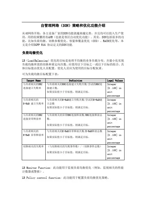
其实,SON包括很多的功能,比如负荷均衡、切换参数优化、容量和覆盖优化(CCO)、RACH优化等,本文是介绍3GPP R16 协议定义的SON功能.负荷均衡优化LB(Load Balancing)优化的目标是处理不均衡的业务负载分布,并最小化实现负载均衡所需的切换和重定向次数。
应使用以下目标之一或以下目标的组合。
具体目标值由优化人员配置。
优化人员应为使用的目标分配权重。
可为负载均衡目标配置下表:LB Monitor Function: 此功能用于监视负荷均衡优化(例如,监视相关的性能计数器或警报)。
LB Policy control function: 此功能用于配置负荷均衡优化策略。
图1:负荷均衡部署架构对于负载均衡,SON LB 决策算法位于eNB 中。
IRPManager 可以收集与负荷均衡相关的性能度量。
切换参数优化功能对于LTE 系统内,应使用以下目标之一或以下目标的组合。
具体目标值由优化人员配置。
优化人员应为使用的目标分配权重。
Target Name DefinitionLegal Values 切换相关失败率(与切换相关的失败事件数)/(切换事件总数) 如果实际值小于目标值,则满足目标。
Integer [0..100] in unit percentage在实现优化人员配置的其他目标的情况下,应始终追求最小化不必要切换次数的目标。
此目标可能不需要配置目标值。
下表是切换涉及的参数。
NM (IRPManager)DM eNBItf-NeNBEMLBLBLB Monitor FunctionLB Policy Control FunctionX2eNB LBLB Monitor FunctionLB Policy Control FunctionX2EM表1. 同频和异频切换涉及的切换优化参数表2. 异系统切换优化参数HO参数优化功能重点检测过早切换、过晚切换以及HO导致的网络资源使用率低下。

rats体系结构-回复r a t s体系结构在计算机科学中是一个用于描述和分析分布式系统的框架。
它的名字是一个缩写,代表了四个基本因素:可靠性(Reliability)、可用性(Availability)、可扩展性(Scalability)和可管理性(Manageability)。
本文将对每个因素进行详细解释,以及它们在架构设计中的应用。
可靠性是指系统在面对各种故障情况下能够保持正常运行的能力。
在分布式系统中,故障是不可避免的。
硬件故障、网络中断、软件错误等问题可能导致系统的某些部分无法正常工作。
为了保证可靠性,rats体系结构通过复制和冗余来提供容错能力。
通过将数据和功能复制到不同的节点上,当一个节点出现故障时,其他节点可以继续提供服务。
此外,rats体系结构还提供了故障检测和恢复机制,以便在发生故障时能够及时发现并采取相应的措施。
可用性是指系统对用户请求的响应能力。
用户希望系统能够始终可用,并在短时间内对请求做出回应。
为了实现高可用性,rats体系结构采用了分布式缓存和负载均衡等策略。
分布式缓存可以将数据在多个节点上进行存储,从而提高访问速度;而负载均衡可以将用户请求分配到不同的节点上,避免单点故障和过载。
此外,rats体系结构还支持水平扩展,即增加节点以应对更高的用户负载。
可扩展性是指系统能够支持不断增长的用户和数据量而不降低性能的能力。
分布式系统面临的一个挑战是随着用户数量的增加,系统的性能会下降。
为了解决这个问题,rats体系结构采用了水平扩展和垂直扩展两种方式。
水平扩展通过增加节点来分摊负载,从而提高系统的吞吐量;而垂直扩展则是增加单个节点的计算和存储资源,以提高单个节点的处理能力。
通过这些扩展策略,rats体系结构可以应对不断增长的需求。
可管理性是指系统能够方便地进行监控、维护和管理的能力。
分布式系统通常由许多节点组成,这些节点可能位于不同的地理位置上。
为了方便管理,rats体系结构提供了统一的接口和管理工具。
主要文档Nginx功能概述Nginx功能概述HTTP基础功能:处理静态文件,索引文件以及自动索引;反向代理加速(无缓存),简单的负载均衡和容错;FastCGI,简单的负载均衡和容错;模块化的结构。
过滤器包括gzipping, byte ranges, chunked responses, 以及 SSI-filter 。
在SSI过滤器中,到同一个 proxy 或者 FastCGI 的多个子请求并发处理;SSL 和 TLS SNI 支持;IMAP/POP3 代理服务功能:使用外部 HTTP 认证服务器重定向用户到 IMAP/POP3 后端;使用外部 HTTP 认证服务器认证用户后连接重定向到内部的 SMTP 后端;认证方法:POP3: POP3 USER/PASS, APOP, AUTH LOGIN PLAIN CRAM-MD5;IMAP: IMAP LOGIN;SMTP: AUTH LOGIN PLAIN CRAM-MD5;SSL 支持;在 IMAP 和 POP3 模式下的 STARTTLS 和 STLS 支持;支持的操作系统:FreeBSD 3.x, 4.x, 5.x, 6.x i386; FreeBSD 5.x, 6.x amd64;Linux 2.2, 2.4, 2.6 i386; Linux 2.6 amd64;Solaris 8 i386; Solaris 9 i386 and sun4u; Solaris 10 i386;MacOS X (10.4) PPC;结构与扩展:一个主进程和多个工作进程。
工作进程是单线程的,且不需要特殊授权即可运行;kqueue (FreeBSD 4.1+), epoll (Linux 2.6+), rt signals (Linux 2.2.19+), /dev/poll (Solaris 711/99+), select, 以及 poll 支持;kqueue支持的不同功能包括 EV_CLEAR, EV_DISABLE (临时禁止事件), NOTE_LOWAT, EV_EOF,有效数据的数目,错误代码;sendfile (FreeBSD 3.1+), sendfile (Linux 2.2+), sendfile64 (Linux 2.4.21+), 和 sendfilev (Solaris 8 7/01+) 支持;输入过滤 (FreeBSD 4.1+) 以及 TCP_DEFER_ACCEPT (Linux 2.4+) 支持;10,000 非活动的 HTTP keep-alive 连接仅需要 2.5M 内存。
RFC逻辑定律SAP 高级应用开发 - RFCRFC Remote function Call 远程功能调用, 是SAP系统之间以及非SAP系统之间程序通信的基本接口技术. 例如BAPI , ALE都是基于RFC实现的RFC连接类型:1.类型2: R/2连接2.类型3: ABAP连接或R/3连接,指定主机名和通信服务3.类型I:内部连接,与当前系统连接到同一ABAP系统中,预定义无法修改,与SM51中所显示的应用服务器名相同4.类型L:逻辑目标,通常工作流系统指定过程中配置的RFC目标即为该类型的逻辑目标5.类型X:指定安装了特殊的ABAP设备驱动程序的系统,必须制定ABAP设备驱动程序名6.类型S:通过SNA或APPC启动的外部程序连接7.类型M:通过CMC到ABAP系统的异步RFC连接8.类型T:通过TCP/IP并使用RFC库或SAP连接器的外部程序连接;分为启动(指定主机名、程序路径名)和注册(RFC服务器程序)两种连接模式。
9.类型G:定义外部系统到本地HTTP连接10.类型H:定义ABAP系统到本地的HTTP连接远程调用RFM:1.远程目标可以是文字或变量,其值为SAP系统中一直的远程目标系统。
2.若远程系统是当前系统中的SAP应用服务器,也可以直接指定应用服务器名称,则SM59中的I类型目标3.SM59定义的RFC目标是区分大小写的。
DESTINATION附加项中目标变量的值必须与其完全一致通过CALL FUNCTION语句进行远程功能调用时,可形成不同的调用模式:1. CALL FUNCTION DESTINATION 以同步RFC方式实现RFM 调用,若后面无其他附加项,则形成同步RFC调用,调用程序等待远程调用结果以继续执行2. CALL FUNCTION STARTING NEW TASK 以异步RFC方式实现RFM调用,调用程序不等待远程调用结果继续执行,结果将在回调子程序(callback subroutine)中接收3. CALL FUNCTION IN BACKROUND TASK 以事务性RFC方式实现RFM调用,远程功能暂不开始执行,等待COMMIT WORK 语句出现时,一次性执行一个或多个远程功能远程功能调用时,仅允许通过值传递参数,不能进行引用传递,因为在RFC过程中,可以传递参数,并返回结果,但不能改变调用程序的上下文对表类型参数,在本地普通功能调用中默认为引用传递,不需要创建内表的本地副本,但RFC不支持引用传递机制,将进行隐式的值传递调用,必须在RFC客户和RFC服务器之间交换整个表,只传输实际表格,如果没有指定表参数,则在被调用功能中使用空表RFC 创建连接类型时:1.LOAD BALANCING选择NO:指定TARGET HOST,SYSTEM NUMBER2. LOAD BALANCING选择YES,要指定TARGET SYSTEM (SM51),MESSAGE SERVER(RZ03),GROUP(SMLG)除去SM59定义的远程目标之外,SAP提供两个预定义目标,可以再CALL FUNCTION 语句的DESTINATION附加附件中使用:l目标NONE,将运行当前程序的应用服务器作为目标系统,调用过程将通过RFC接口实现,并拥有RFC上下文,应用于任意调用类型l目标BACK,用于被远程调用的RFM内部的CALL FUNCTION 语句中的目标制定,通过已建立的RFC连接反过来调用该模块的调用者或已载入的其他功能模块SAP ABAP 系统间的RFC实现(通过RFM实现)远程调用RFM:1.远程目标可以是文字或变量,其值为SAP系统中一直的远程目标系统。
稀疏矩阵csr存储规则
稀疏矩阵CSR存储规则是一种用于高效存储和处理稀疏矩阵的方法。
稀疏矩阵是指大部分元素为零的矩阵,而CSR(Compressed Sparse Row)存储规则则是一种基于行压缩的存储方式。
在CSR存储规则中,矩阵被分解为三个数组,值数组(values array)、列索引数组(column index array)和行偏移数组(row offset array)。
这种方式的存储规则可以大大减少存储空间,并且能够提高矩阵运算的效率。
在值数组中,存储了矩阵中所有非零元素的值,按照它们在矩阵中出现的顺序排列。
列索引数组则存储了每个非零元素所在的列号,而行偏移数组则记录了每一行的第一个非零元素在值数组中的位置。
通过这种存储方式,我们可以快速定位矩阵中的非零元素,并且能够高效地进行矩阵运算,比如矩阵乘法、矩阵向量乘法等。
这对于处理大规模稀疏矩阵的应用非常重要,比如在图像处理、网络分析、物理模拟等领域。
总的来说,稀疏矩阵CSR存储规则是一种非常有效的矩阵存储和处理方法,能够帮助我们更高效地处理大规模稀疏矩阵,提高计算效率,减少内存占用。
这种存储规则在实际应用中得到了广泛的应用,对于处理大规模数据和复杂计算任务有着重要的意义。
Network Working Group J. Ash Request for Comments: 4126 AT&T Category: Experimental June 2005 Max Allocation with Reservation Bandwidth Constraints Model forDiffserv-aware MPLS Traffic Engineering & Performance Comparisons Status of This MemoThis memo defines an Experimental Protocol for the Internetcommunity. It does not specify an Internet standard of any kind.Discussion and suggestions for improvement are requested.Distribution of this memo is unlimited.Copyright NoticeCopyright (C) The Internet Society (2005).AbstractThis document complements the Diffserv-aware MPLS Traffic Engineering (DS-TE) requirements document by giving a functional specificationfor the Maximum Allocation with Reservation (MAR) BandwidthConstraints Model. Assumptions, applicability, and examples of theoperation of the MAR Bandwidth Constraints Model are presented. MAR performance is analyzed relative to the criteria for selecting aBandwidth Constraints Model, in order to provide guidance to userimplementation of the model in their networks.Table of Contents1. Introduction (2)1.1. Specification of Requirements (3)2. Definitions (3)3. Assumptions & Applicability (5)4. Functional Specification of the MAR BandwidthConstraints Model (6)5. Setting Bandwidth Constraints (7)6. Example of MAR Operation (8)7. Summary (9)8. Security Considerations (10)9. IANA Considerations (10)10. Acknowledgements (10)A. MAR Operation & Performance Analysis (11)B. Bandwidth Prediction for Path Computation (19)Normative References (20)Informative References (20)Ash Experimental [Page 1]1. IntroductionDiffserv-aware MPLS traffic engineering (DS-TE) requirements andprotocol extensions are specified in [DSTE-REQ, DSTE-PROTO]. Arequirement for DS-TE implementation is the specification ofBandwidth Constraints Models for use with DS-TE. The BandwidthConstraints Model provides the ’rules’ to support the allocation ofbandwidth to individual class types (CTs). CTs are groupings ofservice classes in the DS-TE model, which are provided separatebandwidth allocations, priorities, and QoS objectives. Several CTscan share a common bandwidth pool on an integrated, multiserviceMPLS/Diffserv network.This document is intended to complement the DS-TE requirementsdocument [DSTE-REQ] by giving a functional specification for theMaximum Allocation with Reservation (MAR) Bandwidth ConstraintsModel. Examples of the operation of the MAR Bandwidth ConstraintsModel are presented. MAR performance is analyzed relative to thecriteria for selecting a Bandwidth Constraints Model, in order toprovide guidance to user implementation of the model in theirnetworks.Two other Bandwidth Constraints Models are being specified for use in DS-TE:1. Maximum Allocation Model (MAM) [MAM] - the maximum allowablebandwidth usage of each CT is explicitly specified.2. Russian Doll Model (RDM) [RDM] - the maximum allowable bandwidthusage is done cumulatively by grouping successive CTs according to priority classes.MAR is similar to MAM in that a maximum bandwidth allocation is given to each CT. However, through the use of bandwidth reservation andprotection mechanisms, CTs are allowed to exceed their bandwidthallocations under conditions of no congestion but revert to theirallocated bandwidths when overload and congestion occurs.All Bandwidth Constraints Models should meet these objectives:1. applies equally when preemption is either enabled or disabled(when preemption is disabled, the model still works ’reasonably’well),2. bandwidth efficiency, i.e., good bandwidth sharing among CTs under both normal and overload conditions,Ash Experimental [Page 2]3. bandwidth isolation, i.e., a CT cannot hog the bandwidth ofanother CT under overload conditions,4. protection against QoS degradation, at least of the high-priority CTs (e.g., high-priority voice, high-priority data, etc.), and5. reasonably simple, i.e., does not require additional IGPextensions and minimizes signaling load processing requirements.In Appendix A, modeling analysis is presented that shows the MARModel meets all of these objectives and provides good networkperformance, relative to MAM and full-sharing models, under normaland abnormal operating conditions. It is demonstrated that MARsimultaneously achieves bandwidth efficiency, bandwidth isolation,and protection against QoS degradation without preemption.In Section 3 we give the assumptions and applicability; in Section 4 a functional specification of the MAR Bandwidth Constraints Model;and in Section 5 we give examples of its operation. In Appendix A,MAR performance is analyzed relative to the criteria for selecting a Bandwidth Constraints Model, in order to provide guidance to userimplementation of the model in their networks. In Appendix B,bandwidth prediction for path computation is discussed.1.1. Specification of RequirementsThe key words "MUST", "MUST NOT", "REQUIRED", "SHALL", "SHALL NOT","SHOULD", "SHOULD NOT", "RECOMMENDED", "MAY", and "OPTIONAL" in this document are to be interpreted as described in [RFC2119].2. DefinitionsFor readability a number of definitions from [DSTE-REQ, DSTE-PROTO]are repeated here:Traffic Trunk: an aggregation of traffic flows of the same class (i.e., treated equivalently from the DS-TEperspective), which is placed inside a LabelSwitched Path (LSP).Class-Type (CT): the set of Traffic Trunks crossing a link that is governed by a specific set of bandwidthconstraints. CT is used for the purposes of link bandwidth allocation, constraint-based routing,and admission control. A given Traffic Trunkbelongs to the same CT on all links.Ash Experimental [Page 3]Up to 8 CTs (MaxCT = 8) are supported. They are referred to as CTc, 0 <= c <= MaxCT-1 = 7. Each CT is assigned either a Bandwidth Constraint, or a set of Bandwidth Constraints. Up to 8Bandwidth Constraints (MaxBC = 8) are supportedand they are referred to as BCc, 0 <= c <=MaxBC-1 = 7.TE-Class: A pair of: a) a CT, and b) a preemption priority allowed for that CT. This means that an LSP,transporting a Traffic Trunk from that CT, canuse that preemption priority as the set-uppriority, the holding priority, or both.MAX_RESERVABLE_BWk: maximum reservable bandwidth on link k specifies the maximum bandwidth that may be reserved; this may be greater than the maximum link bandwidth,in which case the link may be oversubscribed[OSPF-TE].BCck: bandwidth constraint for CTc on link k =allocated (minimum guaranteed) bandwidth for CTc on link k (see Section 4).RBW_THRESk: reservation bandwidth threshold for link k (seeSection 4).RESERVED_BWck: reserved bandwidth-in-progress on CTc on link k(0 <= c <= MaxCT-1), RESERVED_BWck = total amount of the bandwidth reserved by all the established LSPs that belong to CTc.UNRESERVED_BWk: unreserved link bandwidth on link k specifies the amount of bandwidth not yet reserved for any CT, UNRESERVED_BWk = MAX_RESERVABLE_BWk - sum[RESERVED_BWck (0 <= c <= MaxCT-1)].UNRESERVED_BWck: unreserved link bandwidth on CTc on link kspecifies the amount of bandwidth not yetreserved for CTc, UNRESERVED_BWck =UNRESERVED_BWk - delta0/1(CTck) * RBW-THRESkwheredelta0/1(CTck) = 0 if RESERVED_BWck < BCckdelta0/1(CTck) = 1 if RESERVED_BWck >= BCckAsh Experimental [Page 4]A number of recovery mechanisms under investigation in the IETF take advantage of the concept of bandwidth sharing across particular sets of LSPs. "Shared Mesh Restoration" in [GMPLS-RECOV] and "Facility-based Computation Model" in [MPLS-BACKUP] are example mechanisms that increase bandwidth efficiency by sharing bandwidth across backup LSPs protecting against independent failures. To ensure that the notionof RESERVED_BWck introduced in [DSTE-REQ] is compatible with such aconcept of bandwidth sharing across multiple LSPs, the wording of the definition provided in [DSTE-REQ] is generalized. With thisgeneralization, the definition is compatible with Shared MeshRestoration defined in [GMPLS-RECOV], so that DS-TE and Shared MeshProtection can operate simultaneously, under the assumption thatShared Mesh Restoration operates independently within each DS-TEClass-Type and does not operate across Class-Types. For example,backup LSPs protecting primary LSPs of CTc also need to belong toCTc; excess traffic LSPs that share bandwidth with backup LSPs of CTc also need to belong to CTc.3. Assumptions & ApplicabilityIn general, DS-TE is a bandwidth allocation mechanism for differentclasses of traffic allocated to various CTs (e.g., voice, normaldata, best-effort data). Network operation functions such ascapacity design, bandwidth allocation, routing design, and networkplanning are normally based on traffic-measured load and forecast[ASH1].As such, the following assumptions are made according to theoperation of MAR:1. Connection admission control (CAC) allocates bandwidth for network flows/LSPs according to the traffic load assigned to each CT,based on traffic measurement and forecast.2. CAC could allocate bandwidth per flow, per LSP, per traffic trunk, or otherwise. That is, no specific assumption is made about aspecific CAC method, except that CT bandwidth allocation isrelated to the measured/forecasted traffic load, as per assumption #1.3. CT bandwidth allocation is adjusted up or down according tomeasured/forecast traffic load. No specific time period isassumed for this adjustment, it could be short term (seconds,minutes, hours), daily, weekly, monthly, or otherwise.Ash Experimental [Page 5]4. Capacity management and CT bandwidth allocation thresholds (e.g., BCc) are designed according to traffic load, and are based ontraffic measurement and forecast. Again, no specific time period is assumed for this adjustment, it could be short term (hours),daily, weekly, monthly, or otherwise.5. No assumption is made on the order in which traffic is allocatedto various CTs; again traffic allocation is assumed to be basedonly on traffic load as it is measured and/or forecast.6. If link bandwidth is exhausted on a given path for aflow/LSP/traffic trunk, alternate paths may be attempted tosatisfy CT bandwidth allocation.Note that the above assumptions are not unique to MAR, but aregeneric, common assumptions for all BC Models.4. Functional Specification of the MAR Bandwidth Constraints ModelA DS-TE Label Switching Router (LSR) that implements MAR MUST support enforcement of bandwidth constraints, in compliance with thespecifications in this section.In the MAR Bandwidth Constraints Model, the bandwidth allocationcontrol for each CT is based on estimated bandwidth needs, bandwidth use, and status of links. The Label Edge Router (LER) makes neededbandwidth allocation changes, and uses [RSVP-TE], for example, todetermine if link bandwidth can be allocated to a CT. Bandwidthallocated to individual CTs is protected as needed, but otherwise it is shared. Under normal, non-congested network conditions, allCTs/services fully share all available bandwidth. When congestionoccurs for a particular CTc, bandwidth reservation prohibits traffic from other CTs from seizing the allocated capacity for CTc.On a given link k, a small amount of bandwidth RBW_THRESk (thereservation bandwidth threshold for link k) is reserved and governsthe admission control on link k. Also associated with each CTc onlink k are the allocated bandwidth constraints BCck to governbandwidth allocation and protection. The reservation bandwidth on a link (RBW_THRESk) can be accessed when a given CTc has bandwidth-in- use (RESERVED_BWck) below its allocated bandwidth constraint (BCck). However, if RESERVED_BWck exceeds its allocated bandwidth constraint (BCck), then the reservation bandwidth (RBW_THRESk) cannot beaccessed. In this way, bandwidth can be fully shared among CTs ifavailable, but is otherwise protected by bandwidth reservationmethods.Ash Experimental [Page 6]Bandwidth can be accessed for a bandwidth request = DBW for CTc on a given link k based on the following rules:Table 1: Rules for Admitting LSP Bandwidth Request = DBW on Link kFor LSP on a high priority or normal priority CTc:If RESERVED_BWck <= BCck: admit if DBW <= UNRESERVED_BWkIf RESERVED_BWck > BCck: admit if DBW <= UNRESERVED_BWk - RBW_THRESk; or, equivalently:If DBW <= UNRESERVED_BWck, admit the LSP.For LSP on a best-effort priority CTc:allocated bandwidth BCck = 0;Diffserv queuing admits BE packets only if there is available linkbandwidth.The normal semantics of setup and holding priority are applied in the MAR Bandwidth Constraints Model, and cross-CT preemption is permitted when preemption is enabled.The bandwidth allocation rules defined in Table 1 are illustratedwith an example in Section 6 and simulation analysis in Appendix A. 5. Setting Bandwidth ConstraintsFor a normal priority CTc, the bandwidth constraints BCck on link kare set by allocating the maximum reservable bandwidth(MAX_RESERVABLE_BWk) in proportion to the forecast or measuredtraffic load bandwidth (TRAF_LOAD_BWck) for CTc on link k. That is: PROPORTIONAL_BWck = TRAF_LOAD_BWck/[sum {TRAF_LOAD_BWck, c=0, MaxCT-1}] X MAX_RESERVABLE_BWkFor normal priority CTc:BCck = PROPORTIONAL_BWckFor a high priority CT, the bandwidth constraint BCck is set to amultiple of the proportional bandwidth. That is:For high priority CTc:BCck = FACTOR X PROPORTIONAL_BWckwhere FACTOR is set to a multiple of the proportional bandwidth(e.g., FACTOR = 2 or 3 is typical). This results in some ’over-allocation’ of the maximum reservable bandwidth, and gives priority Ash Experimental [Page 7]to the high priority CTs. Normally the bandwidth allocated to highpriority CTs should be a relatively small fraction of the total link bandwidth, with a maximum of 10-15 percent being a reasonableguideline.As stated in Section 4, the bandwidth allocated to a best-effortpriority CTc should be set to zero. That is:For best-effort priority CTc:BCck = 06. Example of MAR OperationIn the example, assume there are three class-types: CT0, CT1, CT2.We consider a particular link withMAX-RESERVABLE_BW = 100And with the allocated bandwidth constraints set as follows:BC0 = 30BC1 = 20BC2 = 20These bandwidth constraints are based on the normal traffic loads, as discussed in Section 5. With MAR, any of the CTs is allowed toexceed its bandwidth constraint (BCc) as long a there are at leastRBW_THRES (reservation bandwidth threshold on the link) units ofspare bandwidth remaining. Let’s assumeRBW_THRES = 10So under overload, ifRESERVED_BW0 = 50RESERVED_BW1 = 30RESERVED_BW2 = 10Therefore, for this loadingUNRESERVED_BW = 100 - 50 - 30 - 10 = 10CT0 and CT1 can no longer increase their bandwidth on the link,because they are above their BC values and there is only RBW_THRES=10 units of spare bandwidth left on the link. But CT2 can take theadditional bandwidth (up to 10 units) if the demand arrives, because it is below its BC value.Ash Experimental [Page 8]As also discussed in Section 4, if best effort traffic is present, it can always seize whatever spare bandwidth is available on the link at the moment, but is subject to being lost at the queues in favor ofthe higher priority traffic.Let’s say an LSP arrives for CT0 needing 5 units of bandwidth (i.e., DBW = 5). We need to decide, based on Table 1, whether to admit this LSP or not. Since for CT0RESERVED_BW0 > BC0 (50 > 30), andDBW > UNRESERVED_BW - RBW_THRES (i.e., 5 > 10 - 10)Table 1 says the LSP is rejected/blocked.Now let’s say an LSP arrives for CT2 needing 5 units of bandwidth(i.e., DBW = 5). We need to decide based on Table 1 whether to admit this LSP or not. Since for CT2RESERVED_BW2 < BC2 (10 < 20), andDBW < UNRESERVED_BW (i.e., 5 < 10)Table 1 says to admit the LSP.Hence, in the above example, in the current state of the link and in the current CT loading, CT0 and CT1 can no longer increase theirbandwidth on the link, because they are above their BCc values andthere is only RBW_THRES=10 units of spare bandwidth left on the link. But CT2 can take the additional bandwidth (up to 10 units) if thedemand arrives, because it is below its BCc value.7. SummaryThe proposed MAR Bandwidth Constraints Model includes the following:1. allocation of bandwidth to individual CTs,2. protection of allocated bandwidth by bandwidth reservationmethods, as needed, but otherwise full sharing of bandwidth,3. differentiation between high-priority, normal-priority, and best- effort priority services, and4. provision of admission control to reject connection requests, when needed, in order to meet performance objectives.The modeling results presented in Appendix A show that MAR bandwidth allocation achieves a) greater efficiency in bandwidth sharing while still providing bandwidth isolation and protection against QoSAsh Experimental [Page 9]degradation, and b) service differentiation for high-priority,normal-priority, and best-effort priority services.8. Security ConsiderationsSecurity considerations related to the use of DS-TE are discussed in [DSTE-PROTO]. They apply independently of the Bandwidth Constraints Model, including the MAR specified in this document.9. IANA Considerations[DSTE-PROTO] defines a new name space for "Bandwidth ConstraintsModel Id". The guidelines for allocation of values in that namespace are detailed in Section 13.1 of [DSTE-PROTO]. In accordancewith these guidelines, the IANA has assigned a Bandwidth Constraints Model Id for MAR from the range 0-239 (which is to be managed as per the "Specification Required" policy defined in [IANA-CONS]).Bandwidth Constraints Model Id 2 was allocated by IANA to MAR.10. AcknowledgementsDS-TE and Bandwidth Constraints Models have been an active area ofdiscussion in the TEWG. I would like to thank Wai Sum Lai for hissupport and review of this document. I also appreciate helpfuldiscussions with Francois Le Faucheur.Ash Experimental [Page 10]Appendix A. MAR Operation & Performance AnalysisA.1. MAR OperationIn the MAR Bandwidth Constraints Model, the bandwidth allocationcontrol for each CT is based on estimated bandwidth needs, bandwidth use, and status of links. The LER makes needed bandwidth allocation changes, and uses [RSVP-TE], for example, to determine if linkbandwidth can be allocated to a CT. Bandwidth allocated toindividual CTs is protected as needed, but otherwise it is shared.Under normal, non-congested network conditions, all CTs/servicesfully share all available bandwidth. When congestion occurs for aparticular CTc, bandwidth reservation acts to prohibit traffic fromother CTs from seizing the allocated capacity for CTc. Associatedwith each CT is the allocated bandwidth constraint (BCc) whichgoverns bandwidth allocation and protection; these parameters areillustrated with examples in this Appendix.In performing MAR bandwidth allocation for a given flow/LSP, the LER first determines the egress LSR address, service-identity, and CT.The connection request is allocated an equivalent bandwidth to berouted on a particular CT. The LER then accesses the CT priority,QoS/traffic parameters, and routing table between the LER and egress LSR, and sets up the connection request using the MAR bandwidthallocation rules. The LER selects a first-choice path and determines if bandwidth can be allocated on the path based on the MAR bandwidth allocation rules given in Section 4. If the first choice path hasinsufficient bandwidth, the LER may then try alternate paths, andagain applies the MAR bandwidth allocation rules now described.MAR bandwidth allocation is done on a per-CT basis, in whichaggregated CT bandwidth is managed to meet the overall bandwidthrequirements of CT service needs. Individual flows/LSPs areallocated bandwidth in the corresponding CT according to CT bandwidth availability. A fundamental principle applied in MAR bandwidthallocation methods is the use of bandwidth reservation techniques.Bandwidth reservation gives preference to the preferred traffic byallowing it to seize idle bandwidth on a link more easily than thenon-preferred traffic. Burke [BUR] first analyzed bandwidthreservation behavior from the solution of the birth-death equationsfor the bandwidth reservation model. Burke’s model showed therelative lost-traffic level for preferred traffic, which is notsubject to bandwidth reservation restrictions, as compared to non-preferred traffic, which is subject to the restrictions. Bandwidthreservation protection is robust to traffic variations and provides Ash Experimental [Page 11]significant dynamic protection of particular streams of traffic. It is widely used in large-scale network applications [ASH1, MUM, AKI,KRU, NAK].Bandwidth reservation is used in MAR bandwidth allocation to control sharing of link bandwidth across different CTs. On a given link, asmall amount of bandwidth (RBW_THRES) is reserved (perhaps 1% of the total link bandwidth), and the reservation bandwidth can be accessed when a given CT has reserved bandwidth-in-progress (RESERVED_BW)below its allocated bandwidth (BC). That is, if the available linkbandwidth (unreserved idle link bandwidth UNRESERVED_BW) exceedsRBW_THRES, then any CT is free to access the available bandwidth onthe link. However, if UNRESERVED_BW is less than RBW_THRES, then the CT can utilize the available bandwidth only if its current bandwidth usage is below the allocated amount (BC). In this way, bandwidth can be fully shared among CTs if available, but it is protected bybandwidth reservation if below the reservation level.Through the bandwidth reservation mechanism, MAR bandwidth allocation also gives preference to high-priority CTs, in comparison to normal- priority and best-effort priority CTs.Hence, bandwidth allocated to each CT is protected by bandwidthreservation methods, as needed, but otherwise shared. Each LERmonitors CT bandwidth use on each CT, and determines if connectionrequests can be allocated to the CT bandwidth. For example, for abandwidth request of DBW on a given flow/LSP, the LER determines the CT priority (high, normal, or best-effort), CT bandwidth-in-use, and CT bandwidth allocation thresholds, and uses these parameters todetermine the allowed load state threshold to which capacity can beallocated. In allocating bandwidth DBW to a CT on given LSP (forexample, A-B-E), each link in the path is checked for availablebandwidth in comparison to the allowed load state. If bandwidth isunavailable on any link in path A-B-E, another LSP could be tried,such as A-C-D-E. Hence, determination of the link load state isnecessary for MAR bandwidth allocation, and two link load states are distinguished: available (non-reserved) bandwidth (ABW_STATE), andreserved-bandwidth (RBW_STATE). Management of CT capacity uses thelink state and the allowed load state threshold to determine if abandwidth allocation request can be accepted on a given CT.A.2. Analysis of MAR PerformanceIn this Appendix, modeling analysis is presented in which MARbandwidth allocation is shown to provide good network performance,relative to full sharing models, under normal and abnormal operating conditions. A large-scale Diffserv-aware MPLS traffic engineeringsimulation model is used, in which several CTs with differentAsh Experimental [Page 12]priority classes share the pool of bandwidth on a multiservice,integrated voice/data network. MAR methods have also been analyzedin practice for networks that use time division multiplexing (i.e.,TDM-based networks) [ASH1], and in modeling studies for IP-basednetworks [ASH2, ASH3, E.360].All Bandwidth Constraints Models should meet these objectives:1. applies equally when preemption is either enabled or disabled(when preemption is disabled, the model still works ’reasonably’well),2. bandwidth efficiency, i.e., good bandwidth sharing among CTs under both normal and overload conditions,3. bandwidth isolation, i.e., a CT cannot hog the bandwidth ofanother CT under overload conditions,4. protection against QoS degradation, at least of the high-priority CTs (e.g., high-priority voice, high-priority data, etc.), and5. reasonably simple, i.e., does not require additional IGPextensions and minimizes signaling load processing requirements.The use of any given Bandwidth Constraints Model has significantimpacts on the performance of a network, as explained later.Therefore, the criteria used to select a model need to enable us toevaluate how a particular model delivers its performance, relative to other models. Lai [LAI, DSTE-PERF] has analyzed the MAM and RDMModels and provided valuable insights into the relative performanceof these models under various network conditions.In environments where preemption is not used, MAM is attractivebecause a) it is good at achieving isolation, and b) it achievesreasonable bandwidth efficiency with some QoS degradation of lowerclasses. When preemption is used, RDM is attractive because it canachieve bandwidth efficiency under normal load. However, RDM cannot provide service isolation under high load or when preemption is notused.Our performance analysis of MAR bandwidth allocation methods is based on a full-scale, 135-node simulation model of a national network,combined with a multiservice traffic demand model to study variousscenarios and tradeoffs [ASH3, E.360]. Three levels of trafficpriority -- high, normal, and best effort -- are given across 5 CTs: normal priority voice, high priority voice, normal priority data,high priority data, and best effort data.Ash Experimental [Page 13]The performance analyses for overloads and failures include a) theMAR Bandwidth Constraints Model, as specified in Section 4, b) theMAM Bandwidth Constraints Model, and c) the No-DSTE BandwidthConstraints Model.The allocated bandwidth constraints for MAR are described in Section 5 as:Normal priority CTs: BCck = PROPORTIONAL_BWk,High priority CTs: BCck = FACTOR X PROPORTIONAL_BWkBest-effort priority CTs: BCck = 0In the MAM Bandwidth Constraints Model, the bandwidth constraints for each CT are set to a multiple of the proportional bandwidthallocation:Normal priority CTs: BCck = FACTOR1 X PROPORTIONAL_BWk,High priority CTs: BCck = FACTOR2 X PROPORTIONAL_BWkBest-effort priority CTs: BCck = 0Simulations show that for MAM, the sum (BCc) should exceedMAX_RESERVABLE_BWk for better efficiency, as follows:1. The normal priority CTs and the BCc values need to be over-allocated to get reasonable performance. It was found that over- allocating by 100% (i.e., setting FACTOR1 = 2), gave reasonableperformance.2. The high priority CTs can be over-allocated by a larger multipleFACTOR2 in MAM and this gives better performance.The rather large amount of over-allocation improves efficiency, butsomewhat defeats the ’bandwidth protection/isolation’ needed with aBC Model, because one CT can now invade the bandwidth allocated toanother CT. Each CT is restricted to its allocated bandwidthconstraint BCck, which is the maximum level of bandwidth allocated to each CT on each link, as in normal operation of MAM.In the No-DSTE Bandwidth Constraints Model, no reservation orprotection of CT bandwidth is applied, and bandwidth allocationrequests are admitted if bandwidth is available. Furthermore, noqueuing priority is applied to any of the CTs in the No-DSTEBandwidth Constraints Model.Table 2 gives performance results for a six-times overload on asingle network node at Oakbrook, Illinois. The numbers given in the table are the total network percent lost (i.e., blocked) or delayed Ash Experimental [Page 14]。