二氧化钛纳米材料及其能源应用_英文_
- 格式:pdf
- 大小:1.52 MB
- 文档页数:13
纳米二氧化钛在能源和环境治理方面的应用张娜娜;何又青;严尹涛;沈丹青【摘要】With the development of nanometer material technology, the material research field has made further progress. As a new nanomaterial, nanometer titanium dioxide has been widely used in the preparation of energy materials and environmental protection because of its strong photocatalytic effect, good thermal stability, reusable and other characteristics. The nanometer titanium dioxide in the management of water pollution, air pollution, soil restoration, and how to improve the application of solar cell conversion efficiency were introduced. The problems at present, the future development and the application prospect of the future were described.%随着纳米材料技术的发展, 使得材料研究领域又有了更进一步的飞跃.纳米二氧化钛作为一种新兴的纳米材料,因其具有光催化效果强、热稳定好、可重复使用等特性, 使其在能源材料的制备和环境保护等方面得到了广泛的应用.本文着重介绍纳米二氧化钛在水体污染、空气污染的治理, 土壤修复以及提高太阳能电池转化效率等方面的应用, 并对其在现阶段存在的问题和未来的发展及应用前景做出了展望.【期刊名称】《广州化工》【年(卷),期】2018(046)012【总页数】2页(P19-20)【关键词】二氧化钛(TiO2);光催化性能;纳米;应用【作者】张娜娜;何又青;严尹涛;沈丹青【作者单位】宿迁学院信息工程学院,江苏宿迁 223800;宿迁学院信息工程学院,江苏宿迁 223800;宿迁学院信息工程学院,江苏宿迁 223800;宿迁学院信息工程学院,江苏宿迁 223800【正文语种】中文【中图分类】O643.36现代工业化的迅猛发展,除了给人们带来的是经济的飞速发展和生活的安逸,同时还带来了环境方面的污染。
二氧化钛纳米材料二氧化钛(TiO2)是一种重要的功能材料,具有广泛的应用前景。
而纳米材料作为一种特殊的材料形态,具有独特的物理化学性质和应用潜力,因此二氧化钛纳米材料备受关注。
本文将介绍二氧化钛纳米材料的制备方法、性质和应用前景。
首先,二氧化钛纳米材料的制备方法有多种途径。
常见的制备方法包括溶胶-凝胶法、水热法、溶剂热法、气相沉积法等。
其中,溶胶-凝胶法是一种常用的制备方法,通过溶胶的凝胶化和热处理过程,可以得到具有较高比表面积和较小晶粒尺寸的二氧化钛纳米材料。
水热法则是利用高温高压条件下水热反应合成纳米材料,具有简单、环保的特点。
此外,溶剂热法和气相沉积法也是常用的制备方法,它们分别适用于不同形态的纳米材料制备,如纳米颗粒、纳米管、纳米片等。
其次,二氧化钛纳米材料具有许多特殊的性质。
首先,由于其较大的比表面积和较小的晶粒尺寸,二氧化钛纳米材料表现出优异的光催化性能。
其次,二氧化钛纳米材料还具有优异的光电化学性能,可应用于太阳能电池、光催化水分解等领域。
此外,二氧化钛纳米材料还具有优异的光学性能和电化学性能,可应用于传感器、光电器件等领域。
最后,二氧化钛纳米材料具有广泛的应用前景。
在环境领域,二氧化钛纳米材料可应用于水处理、空气净化等方面,具有重要的应用价值。
在能源领域,二氧化钛纳米材料可应用于太阳能电池、光催化水分解等领域,具有重要的推动作用。
在光电子器件领域,二氧化钛纳米材料可应用于传感器、光电器件等方面,具有广阔的市场前景。
综上所述,二氧化钛纳米材料具有重要的科研和应用价值。
随着纳米技术的不断发展,二氧化钛纳米材料的制备方法将更加多样化,其性质和应用前景也将得到更广泛的拓展。
相信在不久的将来,二氧化钛纳米材料将在多个领域展现出重要的作用,为人类社会的可持续发展做出重要贡献。
纳米二氧化钛(TiO2)应用:水处理、催化剂载体、紫外线吸收等
二十世纪纳米技术兴起并迅速发展,由于纳米材料的独特性质使它在科学技术领域占据重要地位。
纳米二氧化钛(TiO2)具有许多的特殊性能比如表面效应、体积效应、量子尺寸效应、宏观量子隧道效应等,从而使其与普通二氧化钛相比具有许多特殊性能。
纳米二氧化钛在水处理、催化剂载体、紫外线吸收剂、光敏性催化剂、防晒护肤化妆品、涂料填料、光电子器件等领域具有广泛的用途。
纳米TiO的制备方法有气相法、液相法。
目前,研究的一个热点是纳米TiO2 作为半导体光催化剂用于废水、废气的净化。
纳米TiO2 具有湿敏、气敏功能,如它对一氧化碳极为敏感,可用在传感器上,尽管我国对纳米二氧化钛的研究起步较晚,但是科技工作者们在其制备和应用上做了大量的工作和深入的研究,并取得了许多成果。
河北麦森钛白粉有限公司生产的纳米二氧化钛(光催化)(MS-GCA01)
产品性能:
本品光催化纳米二氧化钛外观为白色疏松粉末。
在可见光或紫外光的作用下具有很强的氧化还原能力,化学性能稳定,能将甲醛,甲苯,二甲苯,氨,氡,TVOC等有害有机物,污染物,臭气,细菌,病毒,微生物等有害有机物彻底分解成无害的CO2和H2O,并具有去除污染物,亲水性,自洁性等特性,性能持久,不产生二次污染。
本品适合于各种空气污染治理的光触媒喷剂,纳米抗菌涂料,污水处理(可将造纸厂,印染厂,酒精厂和化工厂等废水中的大分子有机物进行降解,使之变成CO2,H2O)纳米抗菌自洁纤维,电子材料等产品,产品比表面大,光催化效率高,分解有害气体速度快,本品吸收紫外线能力强范围广(280nm-460nm)。
5二氧化钛纳米材料的应用现有的二氧化钛纳米材料的应用领域包括涂料,牙膏,防紫外线,光催化,光电,传感,和电致变色以及光色体–这些应用领域前景良好。
二氧化钛纳米材料通常有电子带隙,电子伏特大于3.0,在紫外线区域具有高吸收性。
二氧化钛纳米材料性能非常稳定、无毒、价格便宜。
由于其良好的光学和生物学性能,可应用于紫外线保护。
如果水表面接触角大于130 °或小于5 °,可将表面分别定义为超疏水或超亲水表面。
各种玻璃制品具有防雾功能,如镜子,眼镜,具有超亲水或超疏水表面。
例如,冯等人发现可逆超亲水性和超疏水性,可来回切换二氧化钛纳米薄膜。
用紫外光照射二氧化钛纳米棒薄膜时,光生空穴和晶格氧产生反应,表面氧空缺。
动力学上,水分子与这些氧空缺相协调,球形水滴沿纳米棒填补了凹槽,并且在二氧化钛纳米棒薄膜上分散,接触角约为0°- 这会导致超亲水二氧化钛薄膜。
羟基吸附后,表面转化成大力亚稳态。
如薄膜被放置在黑暗中,被吸附羟基逐渐取代了大气中的氧气,表面回到原始状态。
表面润湿度由超亲水转换成超疏水。
由于超亲水或超疏水表面,许多不同类型的表面具有防污、自洁性能。
电气或光学性质随吸附而产生变化,二氧化钛纳米材料也可用来作为各种气体和湿度传感器。
就未来的清洁能源应用而言,最重要的研究领域之一,是寻找高效电力和/或氢气材料。
如二氧化钛和有机染料或无机窄禁带半导体敏化,二氧化钛能吸收光,形成可见光区域,并将太阳能转换成电能,应用于太阳能电池。
Gratzel领导的小组,运用染料敏化太阳能技术,实现了将所有太阳能转换成电流,转换效率物10.6%电流。
人们广泛研究了二氧化钛纳米材料用于水分解和制氢,这是因为于水氧化还原时,其具有合适的电子能带结构。
二氧化钛纳米材料另外应用- 二氧化钛纳米材料与染料或金属纳米粒子敏化时,形成光致变色。
当然,二氧化钛纳米材料的众多应用之一是光催化分解各种污染物。
5.1光催化应用二氧化钛被认为是最有效的、无害环境的光催化剂,广泛用于各种污染物的降解。
黑色二氧化钛纳米材料研究进展黑色二氧化钛纳米材料是一种新型的纳米材料,由于其独特的物理、化学和光学性质,近年来备受。
本文将概述黑色二氧化钛纳米材料的制备方法、性能研究及其应用前景,并探讨当前研究的不足和未来需要进一步解决的问题。
黑色二氧化钛纳米材料的制备方法主要有化学气相沉积、液相合成和物理气相沉积等。
其中,化学气相沉积法是通过引入气态反应剂,使反应在催化剂表面进行,从而生成纳米材料。
液相合成法是将钛源、氧源和碳源等混合在溶剂中,通过控制反应条件合成出黑色二氧化钛纳米材料。
物理气相沉积法则是将钛源和氧源在高温下蒸发,然后在低温区快速冷凝,生成黑色二氧化钛纳米材料。
黑色二氧化钛纳米材料的性能主要包括物理性能、化学性能和光学性能。
物理性能方面,黑色二氧化钛纳米材料具有高比表面积、高透光性和良好的热稳定性等。
化学性能方面,黑色二氧化钛纳米材料具有优异的耐酸碱性和化学稳定性,能在广泛的环境条件下保持稳定。
光学性能方面,黑色二氧化钛纳米材料具有宽广的可见光透过范围和良好的紫外线屏蔽性能。
由于黑色二氧化钛纳米材料具有优异的性能,其在众多领域都具有广泛的应用前景。
例如,在光催化领域,黑色二氧化钛纳米材料可以用于降解有机污染物和杀菌消毒。
在太阳能电池领域,黑色二氧化钛纳米材料可以作为透明电极材料,提高太阳能电池的光电转化效率。
在涂料领域,黑色二氧化钛纳米材料可以用于制造高效能涂料,提高涂料的防晒、耐污和耐候性能。
黑色二氧化钛纳米材料作为一种新型的纳米材料,具有优异的物理、化学和光学性能,使其在众多领域具有广泛的应用前景。
然而,目前关于黑色二氧化钛纳米材料的研究仍存在不足之处,例如其制备方法尚需进一步优化以提高产量和纯度,同时其应用领域也需要进一步拓展。
未来,研究人员需要进一步解决这些问题,同时深入研究黑色二氧化钛纳米材料的潜在应用价值,为其在更多领域的应用奠定基础。
合成纳米二氧化钛的方法很多,主要包括物理法、化学法以及生物法。
纳米二氧化钛的制备及其应用研究进展摘要:纳米二氧化钛作为一种重要的功能性材料,在光催化、电池、光电器件等领域具有广泛的应用潜力。
本文对纳米二氧化钛的制备方法进行了综述,并探讨了其在不同应用领域的研究进展。
主要包括溶胶-凝胶法、水热法、气相法等一系列制备方法及其优缺点,以及纳米二氧化钛在光催化、电池和光电器件等领域的应用前景。
最后,总结了现有研究中存在的问题,并展望了未来纳米二氧化钛在各个领域的发展趋势。
1. 引言纳米二氧化钛作为一种重要的半导体材料,因其独特的物理、化学性质而受到广泛关注。
其具有高比表面积、优异的光电催化性能、良好的化学稳定性、可控的光吸收能力等特点,使其在光催化、电池、光电器件等领域有着广泛的应用潜力。
在实际应用中,纳米二氧化钛的功能和性能往往与其结构和制备方法密切相关。
因此,研究纳米二氧化钛的制备方法及其应用是目前材料科学和化学领域的热点之一。
2. 纳米二氧化钛的制备方法2.1 溶胶-凝胶法溶胶-凝胶法是一种常用的纳米二氧化钛制备方法。
该方法通过将金属前驱物溶解在有机或无机溶剂中,生成溶胶,然后通过控制溶胶的凝胶过程,形成纳米二氧化钛颗粒。
由于溶胶-凝胶法制备过程相对简单、可控性强,使得纳米二氧化钛的晶粒尺寸和形貌可以通过控制溶胶的成分、浓度、PH值等条件来调节。
然而,溶胶-凝胶法制备纳米二氧化钛的缺点是制备周期长,需要较高温度和长时间的热处理。
2.2 水热法水热法是一种采用高温高压水作为反应介质,将金属前体转化为纳米二氧化钛的制备方法。
水热法可以在相对较低的温度下制备出高度结晶的纳米二氧化钛颗粒,其晶形和晶面可通过调节反应温度和时间来控制。
由于水热法制备过程相对简单,且无需添加昂贵的添加剂,因此被广泛应用于纳米二氧化钛的制备。
2.3 气相法气相法是指将气体或气态前体转化为纳米二氧化钛的制备方法。
传统的气相法将有机金属化合物蒸汽通过热分解或水解,控制反应条件,形成纳米二氧化钛颗粒。

纳米二氧化钛的制备及其在环保领域的应用纳米二氧化钛的制备及其在环保领域的应用一、引言地球资源的有限性和环境问题的日益严重,使得环保领域的研究与应用成为了当下的热点。
作为一种具有良好光催化活性和化学稳定性的纳米材料,纳米二氧化钛因其卓越的性能而备受关注,并在环保领域显示出广泛的应用前景。
二、纳米二氧化钛的制备方法纳米二氧化钛的制备方法有多种,常见的有溶胶-凝胶法、水热法、溶剂热法、水热-溶胶凝胶法等。
下面将介绍一种常用的制备方法——溶胶-凝胶法。
首先,将钛酸四酯等钛源溶解于适量氯化氢水溶液中。
然后进行水解反应,控制反应温度和pH值,使得溶液中的钛离子发生水解生成氢氧化钛。
接着通过酸加热处理或直接加热,使氢氧化钛凝胶生成金红石型TiO2固体。
最后,经过洗涤、过滤、烘干等步骤,得到纳米二氧化钛粉末。
三、纳米二氧化钛在清洁能源领域的应用1.光催化降解有机污染物纳米二氧化钛具有优异的光催化活性,可以利用光照将有机污染物降解为无害物质。
然而,纳米二氧化钛本身的光吸收范围主要集中在紫外光区域,限制了其在可见光区域的光催化活性。
为了解决这一问题,研究者们通过掺杂、修饰等方法,对纳米二氧化钛进行改进,提高其在可见光区域的光吸收能力。
例如,将纳米二氧化钛与纳米碳管复合,形成TiO2/N-CNT异质结构,提高了纳米二氧化钛的吸光性能,使其具备了可见光催化降解有机污染物的能力。
2.光催化水分解产氢利用纳米二氧化钛的光催化性质,通过光照反应将水分解为氧气和氢气,可作为一种清洁的氢能源生成方法。
研究者通过改变纳米二氧化钛的结构和形貌,提高其光催化水分解的效率。
例如,将纳米二氧化钛与金属催化剂负载在载体上,形成复合材料,可以增强材料的光催化性能。
此外,通过表面修饰纳米二氧化钛,改变其表面电子结构,也可提高光催化水分解的效率。
四、纳米二氧化钛在污水处理领域的应用1.有机污染物的去除纳米二氧化钛对有机污染物具有较好的光催化降解性能。
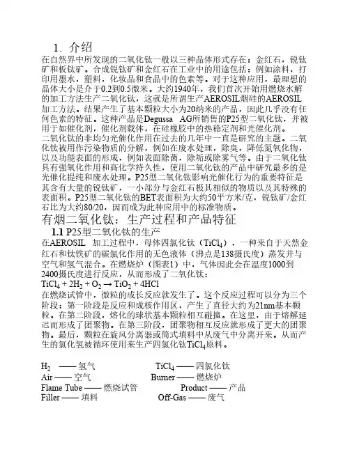
1. 介绍在自然界中所发现的二氧化钛一般以三种晶体形式存在:金红石,锐钛矿和板钛矿。
合成锐钛矿和金红石在工业中的用途包括:例如涂料,打印用墨水,塑料,化妆品和食品中的色素等。
对于这种应用,最理想的晶体大小是介于0.2到0.5微米。
大约1940年,我们首次开始用燃烧水解的加工方法生产二氧化钛,这就是所谓生产AEROSIL烟硅的AEROSIL 加工方法。
结果产生了基本颗粒大小为20纳米的产品,因此几乎没有任何色素的特征。
这种产品是Degussa AG所销售的P25型二氧化钛,并被用于如催化剂,催化剂载体,在硅橡胶中的热稳定剂和光催化剂。
二氧化钛的非均匀光催化作用在过去的几年中一直是研究的主题。
二氧化钛被用作污染物质的分解,例如在废水处理,除臭,降低氮氧化物,以及功能表面的形成,例如表面除菌,除垢或除雾气等。
由于二氧化钛具有强氧化作用和高化学持久性,使用二氧化钛的产品中研究最多的是光催化提纯和废水处理。
P25型二氧化钛影响光催化行为的重要特征是其含有大量的锐钛矿,一小部分与金红石极其相似的物质以及其特殊的表面积。
P25型二氧化钛的BET表面积为大约50平方米/克,锐钛矿/金红石比为大约80/20,因而成为此种应用中的标准物质。
有烟二氧化钛:生产过程和产品特征1.1 P25型二氧化钛的生产在AEROSIL 加工过程中,母体四氯化钛(TiCl4),一种来自于天然金红石和钛铁矿的碳氯化作用的无色液体(沸点是138摄氏度)蒸发并与空气和氢气混合。
在燃烧炉(图表1)中,气体因此会在温度1000到2400摄氏度进行反应,从而形成了二氧化钛:TiCl4 + 2H2 + O2 → TiO2 + 4HCl在燃烧试管中,微粒的成长反应就发生了。
这个反应过程可以分为三个阶段:第一阶段是反应和成核作用区,产生了直径大约为21nm基本颗粒。
在第二阶段,熔化的球状基本颗粒相互碰撞。
在这里,由于熔解延迟而形成了团聚物。
在第三阶段,团聚物相互反应就形成了更大的团聚物。
二氧化钛基纳米材料及其在清洁能源技术中的研究进展一、本文概述随着全球能源需求的日益增长和环境保护的迫切需求,清洁能源技术的研究与应用已成为当前科技领域的重要课题。
其中,二氧化钛基纳米材料因其独特的物理和化学性质,在清洁能源技术中展现出了巨大的应用潜力。
本文旨在综述近年来二氧化钛基纳米材料在清洁能源技术中的研究进展,探讨其光催化、太阳能电池、燃料电池和锂离子电池等领域的应用,以及当前存在的挑战与未来的发展方向。
通过对相关文献的梳理和分析,本文旨在为研究者提供二氧化钛基纳米材料在清洁能源技术中的最新研究进展,为相关领域的深入研究和技术创新提供参考。
二、二氧化钛基纳米材料的制备方法二氧化钛(TiO₂)基纳米材料的制备方法多种多样,每种方法都有其独特的优点和适用场景。
下面将介绍几种主要的制备方法。
溶胶-凝胶法:这是一种常用的制备二氧化钛纳米材料的方法。
通过控制溶液的pH值、反应温度和时间,可以得到不同形貌和尺寸的二氧化钛纳米颗粒。
这种方法的优点是操作简单,反应条件温和,可以制备出高纯度的纳米材料。
然而,溶胶-凝胶法通常需要较长的反应时间,且制备过程中可能会使用到有毒的有机溶剂。
水热法:水热法是在高温高压的水热环境下,使反应物发生化学反应生成目标产物的方法。
通过控制反应温度、压力和时间,可以制备出具有特定形貌和结构的二氧化钛纳米材料。
水热法的优点是能够制备出结晶度高、分散性好的纳米材料。
然而,该方法需要特殊的设备,且制备过程中需要消耗大量的能量。
物理气相沉积法:物理气相沉积法是通过物理手段将气态的原料沉积在基材表面,形成纳米材料的方法。
这种方法可以制备出高质量的二氧化钛纳米薄膜。
物理气相沉积法的优点是制备过程中无需使用化学试剂,可以避免杂质引入。
但是,该方法需要昂贵的设备,且制备过程中可能需要对基材进行特殊处理。
微乳液法:微乳液法是利用表面活性剂在油水界面形成的微小液滴作为反应场所,通过控制液滴的大小和分布来制备纳米材料的方法。
纳米级二氧化钛在电池中的应用在现代科技的浪潮中,咱们的电池也在不断进化。
说到这,大家可能会想,电池不就是那个黑乎乎的块儿吗?其实可不是哦!今天就让咱们来聊聊一个小家伙,纳米级二氧化钛,怎么在电池中扮演着大明星的角色。
这种材料就像那种看起来不起眼的“黑马”,关键时刻却能带来意想不到的惊喜。
先说说纳米级二氧化钛。
听名字就觉得很高科技对吧?实际上,这个小东西的粒子大小非常微小,甚至能跟人类的头发丝比起来小几百倍。
这种细小的颗粒让它在各种应用中大显身手,尤其是在电池里。
咱们电池的性能,简直就像一场华丽的演出,而纳米二氧化钛就是那个炫酷的主角。
它的特性真是让人刮目相看,既能提升电池的容量,又能增加充电速度,简直就是个多面手,真是不得不佩服。
你可能会问,这么神奇的材料,它是怎么做到的呢?纳米级二氧化钛具有优良的导电性和化学稳定性,这就意味着它能在电池工作时提供稳定的电流。
它在充放电的过程中,不会轻易发生反应,简直就像个靠谱的朋友,永远在你身边,支持你。
想想看,电池的充电速度快了,续航时间长了,谁不想拥有这样一款电池呢?这就好比在紧急情况下,电话不再是个“电量不足”的小怪兽,而是个能陪你战斗到底的超级英雄。
更有意思的是,纳米级二氧化钛的应用不止于此哦!它还能通过增加电池内部的表面积,帮助提高能量密度。
这就像是把一个小房间改造成了一个宽敞的仓库,空间大了,能放的东西自然也多了。
这样一来,咱们的电池不仅能装更多的能量,还能在不增加体积的情况下变得更强大。
试想一下,你的手机电池再也不用频繁充电,出门在外也能轻松应对各种需求,简直是科技界的一股清流。
这些都不是纸上谈兵。
纳米级二氧化钛的应用已经在很多电池中逐渐显露头角。
像是一些新型的锂离子电池,已经开始将这种材料作为关键成分。
大家可能不知道,纳米二氧化钛在电池中还能提升循环寿命,这意味着电池能用得更久,就像一位忠诚的老友,陪伴你走过许多个春秋。
这种长久的陪伴,真的是让人感到心安。
纳米二氧化钛在锂电池中的应用引言:锂电池作为一种重要的储能设备,广泛应用于移动电子设备、电动汽车和可再生能源等领域。
为了提高锂电池的性能和稳定性,研究人员一直在寻找新的材料来改进电池的性能。
纳米二氧化钛作为一种有潜力的材料,近年来引起了广泛的关注。
本文将探讨纳米二氧化钛在锂电池中的应用,并分析其优势和挑战。
一、纳米二氧化钛的制备方法纳米二氧化钛可以通过溶胶-凝胶法、水热法、气相沉积法等多种方法制备。
其中,溶胶-凝胶法是一种常用的制备方法,通过控制反应条件和添加剂,可以得到具有不同形貌和尺寸的纳米二氧化钛颗粒。
二、纳米二氧化钛在锂电池正极材料中的应用1. 提高锂离子嵌入/脱嵌速率:纳米二氧化钛具有较大的比表面积和短离子扩散路径,可以提高锂离子在正极材料中的嵌入/脱嵌速率,从而提高电池的充放电性能。
2. 增加电池容量:纳米二氧化钛具有较高的锂离子嵌入容量,可以增加电池的总容量,延长电池的使用时间。
3. 提高电池循环寿命:纳米二氧化钛具有较好的结构稳定性和电化学稳定性,可以减少电池在循环过程中的容量衰减,提高电池的循环寿命。
三、纳米二氧化钛在锂电池负极材料中的应用1. 提高锂离子嵌入/脱嵌速率:纳米二氧化钛可以作为锂电池负极材料的添加剂,通过提高锂离子在负极材料中的嵌入/脱嵌速率,改善电池的充放电性能。
2. 抑制锂枝晶生长:纳米二氧化钛具有较高的表面能和较小的晶粒尺寸,可以抑制锂枝晶的生长,减少电池内部的短路现象,提高电池的安全性能。
3. 提高电池循环寿命:纳米二氧化钛可以减少电池在循环过程中的容量衰减,提高电池的循环寿命。
四、纳米二氧化钛在锂电池中的挑战1. 纳米二氧化钛的制备成本较高,需要进一步降低制备成本。
2. 纳米二氧化钛的导电性较差,需要通过掺杂或复合改进其导电性能。
3. 纳米二氧化钛的循环稳定性有待提高,需要进一步研究其循环衰减机制并寻找解决方法。
结论:纳米二氧化钛作为一种有潜力的材料,在锂电池中具有广阔的应用前景。
纳米二氧化钛在锂电池制作上的应用
随着科技的发展,能源危机愈发严重,因此新能源的开发利用成为了如今炙手可热的话题。
随着美国推出新型电动汽车之后,全球在锂离子电池领域的研究愈发热门。
锂离子电池性能的好坏主要是与其正负极材料、电解液有关,如今可作为锂电池掺杂材料的氧化物有很多,而其中性能最优异的掺杂材料当属纳米二氧化钛(UG-T30D)。
纳米二氧化钛(UG-T30D)在作为锂离子电池正负极掺杂材料上具有低毒性,低耗能,稳定性良好,高倍率且脱嵌锂可逆性好等特点,作为锂电池掺杂材料具有很好的发展前景。
纳米氧化钛作为锂离子电池的掺杂材料特点如下:
(1)纳米二氧化钛(UG-T30D)可以有效地减小锂电池的容量衰减,增加锂电池的稳定性,提高其化学性能。
(2)纳米二氧化钛(UG-T30D)可以提高锂电池首次放电比容量。
(3)纳米二氧化钛(UG-T30D)可降低LiCoO2在放电过程中的极化,使材料具有更高的放电电压及更平稳的放电效果。
(4)适量的纳米二氧化钛(UG-T30D)可以呈疏松状存在,降低了粒子间应力及循环过程中所造成的结构和体积的微小应变,增加电池的稳定性。
二氧化钛纳米管(TiO2Nanotubes)在环境和能源领域的应用纳米结构的二氧化钛因其在光学、生物学、电学等方面的独特性质而成为目前研究的热点之一,并被广泛应用于光催化,光电池,传感器和涂料等方面,尤其是管状纳米二氧化钛,因为具有尺寸可控和高度有序的特性,引起越来越多的关注。
二氧化钛纳米管相对于纳米棒,纳米线等一维纳米结构而言,具有更大的比表面积,即可以提供更多的活性中心,使得二氧化钛纳米管在微电子、光催化、光电转换等领域展现出良好的应用前景。
二氧化钛纳米管的应用主要是在环境领域和能源领域两大方面。
二氧化钛是在水处理领域降解有机污染物的应用最广泛的光催化剂之一,特别是针对污水中的难降解有机物,表现出良好的优势和前景。
研究人员利用二氧化钛TIO2纳米管来降解双酚A(BPA)的实验,结果表明,加入二氧化钛纳米管做催化剂后,BPA的降解率达到了80.1%,比加入一般TIO2纳米颗粒时的降解率高了51.1%,说明了二氧化钛纳米管具有良好的光催化性能。
TIO2纳米管对SDBS的光催化降解表现出较高的光催化活性,10min时SDBS约降解12%,20min时SDBS已降解30%。
TIO2纳米管用在传感器材料中,用来检测氧气,一氧化碳,氢气等,并且已经被证实,TIO2纳米管对一氧化碳,氢气,氨气等气体表现出高敏感性。
这种高气敏活性源于TIO2纳米管特殊的形貌结构和在纳米尺寸上的高度对称性。
因此可用作汽车尾气传感器,通过检测汽车尾气中的氧气含量来控制和减少尾气中的CO和NOx的污染。
自从研究人员发现用紫外光照射TiO2可以分解水并制得氢气以来,光催化分解水制氢成为了一个新的研究领域。
TIO2纳米管用于光裂解技术中,在波长为320-400nm,能量强度为100m.W/cm2的光照射下,H2产生速率达到了960umol/h.W(24mL /h.W),转换效率达6.8%。
在所有报道的光电化学电池中,其H2产生率最高。
二氧化钛纳米材料的形貌控制及其在能源和环境领域的应用共3篇二氧化钛纳米材料的形貌控制及其在能源和环境领域的应用1随着全球工业化和城市化进程的不断提高,环境问题日益突出,对于环境污染的治理和清洁能源的研究已经成为当前全球面临的重大课题之一。
在这个背景下,二氧化钛纳米材料因其在催化、光催化、光电转换等领域应用广泛而备受关注。
二氧化钛纳米材料可通过不同方法制备,包括溶胶-凝胶法、水热法、溶剂热法等等。
从化学合成的角度来看,通过对溶液中的成分及沉淀条件进行控制,可以调控二氧化钛纳米材料的结构和形貌。
其中一种经典的制备方法是溶胶-凝胶法,其制备过程包括溶胶的制备、凝胶的形成和热处理等步骤。
在控制凝胶的形成过程中,可以通过改变水解与缩合反应的速率,调节水解缩合平衡的条件,达到控制二氧化钛纳米材料结构和形貌的目的。
例如,在溶胶-凝胶法制备的二氧化钛纳米材料中,当乳胶稳定剂添加量较少时,形成的二氧化钛主要为十二面体晶型,而当稳定剂添加量增加,形成的二氧化钛主要为四面体晶型。
在催化、光催化、光电转换领域的应用中,形貌控制方法的调整,从而实现二氧化钛纳米材料特定结构或形貌的合成,是非常重要的。
例如,在光催化降解废水等应用中,传统的二氧化钛纳米材料因结晶度和晶粒大小有限,其光催化效率受到限制。
而通过形貌控制方法,制备的具有较大表面积的纳米材料,表面氧含量较高,可以提高光催化反应速率,提高光催化降解废水的效率。
同时,二氧化钛纳米材料在光电转换领域也有广泛的应用。
近年来,人们研究发现,通过形貌控制方法合成的具有高秩序结构的多孔二氧化钛纳米材料,可以作为染料敏化太阳能电池(DSSCs)中的电子传输层。
在这类结构的多孔二氧化钛纳米材料中,光电荷分离效率高,具有较好的光电转换性质。
此外,通过添加掺杂元素(如铬、铁等)和半导体体系(如硫代钙钛矿)等方法,还可以研究和改善其光电性能。
总的来说,二氧化钛纳米材料的形貌控制方法,在能源和环境领域的应用非常广泛。
第30卷 第8期 催 化 学 报 2009年8月V ol. 30 No. 8Chinese Journal of Catalysi sAugust2009文章编号: 0253-9837(2009)08-0839-13综述: 839~851Received date: 29 April 2009.*Corresponding author. Tel: +1-510-486-7140; Fax: +1-510-486-7303; E-mail: XChen3@English edition available online at ScienceDirect (/science/journal/18722067).二氧化钛纳米材料及其能源应用陈晓波劳伦斯伯克利国家实验室, 伯克利, 加利福尼亚 94720, 美国摘要:简要介绍了二氧化钛纳米材料的合成、性质、改性及其在能源方面的应用. 其中合成方法包括溶胶凝胶、水/溶剂热、氧化、沉积和超声/微波助合成法; 性质包括结构和热力学以及电学和光学性质; 改性包括掺杂和敏化; 应用包括光催化、光伏打和光解水.关键词:二氧化钛; 纳米材料; 掺杂; 敏化; 光催化; 光伏打; 光解水 中图分类号:O643 文献标识码:ATitanium Dioxide Nanomaterials and Their Energy ApplicationsCHEN Xiaobo *Lawrence Berkeley National Laboratory, Berkeley, California 94720, USAAbstract: Here we briefly introduce the synthesis, properties, modifications, and energy applications of titanium dioxide nanomaterials. This introduction surveys their synthetic methods (sol/sol-gel, hydro/solvo-thermal, oxidation, deposition, sonochemical, and microwave-assisted approaches), their structural and thermodynamic properties, their modifications (doping and sensitizing), and their applications in photocata-lysis, photovoltaics and solar water splitting.Key words: titanium dioxide; nanomaterial; doping; sensitizing; photocatalysis; photovoltaics; solar water splittingTitanium dioxide (TiO 2) is biocompatible and environ-mentally benign and has been widely used as a pigment [1–3]. Manufacture of titanium dioxide pigment is a com-bination of two distinct processes: base pigment particle production and surface treatment, drying and milling. There are two different process routes used to extract and purify TiO 2 from ore to produce core pigment particles: the sulfate process and the chloride process [4].The sulfate process is the first commercial process for the manufacture of TiO 2. Originally ilmenite is used as a raw material, but beneficiated ores with a much higher TiO 2 assay have been used more recently. The ore is first dried, ground, and classified to ensure efficient sulfation by agita-tion with concentrated sulfuric acid. The resultant metal sulfates are dissolved in water or weak acid, and the solu-tion is treated to ensure that only ferrous-state iron is pre-sent. The solution temperature is reduced to avoid prema-ture hydrolysis and clarified by settling and chemical floc-culation. The clear solution is then further cooled to crystal-lize coarse ferrous sulfate heptahydrate (FeSO 4⋅7H 2O)which is separated from the process. The solution is evapo-rated to a precise composition and hydrolyzed to produce a suspension consisting predominantly of clusters of colloidal hydrous titanium oxide. Precipitation is carefully controlled to achieve the necessary particle size, usually employing a seeding or nucleating technique. The suspension is then separated from the mother liquor and extensively washed to remove residual traces of metallic impurities, using chelat-ing agents if necessary. The washed suspension is treated with chemicals which adjust the physical texture and act as catalysts in the calcination step. This process can produce either anatase or rutile crystal forms depending on additives used prior to calcination.The feedstock for the chloride process is a mineral rutile or synthetic beneficiates containing over 90 percent TiO 2. A suitable ore blend is mixed with a source of carbon and then reacted with chlorine at approximately 900 °C. The reaction yields titanium tetrachloride, TiCl 4, and the chlorides of all the impurities present. The mixed chlorides are cooled and the low-volatile chloride impurities (e.g. iron, manganese,840 催化学报第30卷and chromium) are separated by condensation and removed from the gas stream with any unreacted solid starting mate-rials. The TiCl4 vapor is condensed to a liquid, followed by fractional distillation to produce an extremely pure, color-less, mobile liquid TiCl4 intermediate product, freezing at −24 °C and boiling at 136 °C. The second critical stage in the chloride process is oxidation of the TiCl4 to TiO2 pig-ment particles. Pure titanium tetrachloride is reacted with oxygen in an exothermic reaction to form titanium dioxide and liberate chlorine, which is recycled to the chlorination stage. The high temperature ensures that only the rutile crystal form is produced. After cooling, the gas stream passes through a separator to collect the pigment particles and to remove adsorbed chlorine from the pigment. In both processes, the raw pigment may either be dried, milled, packed, and sold or more likely, especially for rutile pig-ments, surface-treated to produce a range of special prod-ucts for various applications.Recent enormous research efforts dedicated to TiO2 ma-terials have been most fascinated with the discovery of the phenomenon of photocatalytic splitting of water on a TiO2 electrode by Fujishima et al. in 1972 [5–7]. An exponential growth of research activities has been seen in nanoscience and nanotechnology in the past decades [8–15]. TiO2 nano-materials, including nanoparticles, nanorods, nanowires, and nanotubes, are widely investigated for various applications in photocatalysis, photovoltaics, batteries, photonic crystals, sensors, ultraviolet blockers, smart surface coatings, pig-ment, and paints [1–24]. Various methods, such as sol-gel, sol, hydrothermal/solvothermal, physical/chemical vapor deposition, electrodeposition, etc., have been successfully used in making TiO2 nanomaterials. In the nanometer scale, new physical and chemical properties emerge and they vary with the sizes and shapes of the nanomaterials. The move-ment of electrons and holes in semiconductor nanomaterials is governed by the well-known quantum confinement, the transport properties related to phonons and photons are largely affected by the size and geometry of the materials, and the specific surface area and surface-to-volume ratio increase dramatically as the size of a material decreases [8– 13]. The high surface area brought about by small particle size is beneficial to most TiO2-based devices, as it facilitates reaction/interaction between the devices and interacting media, which mainly occurs on the surface and depends on the surface area. As the size, shape, and crystal structure of TiO2 nanomaterials change, not only does surface stability vary, but the transitions between different phases of TiO2 under pressure or heat become size dependent as well.1 Preparation methods1.1 Sol/sol-gel methodsTiO2 nanomaterials have been synthesized with the sol-gel method, a widely used method in making various ceramic materials. In a typical sol-gel process, the hydroly-sis of a titanium alkoxide or halide precursor and subse-quent condensation finally lead to the formation of TiO2 inorganic framework. This process normally proceeds via an acid-catalyzed hydrolysis step of titanium (IV) alkoxide followed by condensation [25–27]. The development of Ti–O–Ti chains through alcoxolation is favored for low content of water, with low hydrolysis rates and excess tita-nium alkoxide in the reaction mixture. Three-dimensional polymeric skeletons with close packing are resulted from the development of Ti–O–Ti chains, since each Ti is coor-dinated with four O atoms. The formation of Ti(OH)4 is favored with high hydrolysis rates. The presence of a large quantity of Ti–OH and insufficient development of three- dimensional polymeric skeletons lead to loosely packed first-order particles. The formation of Ti(OH)4O+H2 by the coordination of water to Ti(OH)4 is favored in the presence of a large excess of water. Closely packed first-order parti-cles are yielded via a three-dimensionally developed gel skeleton. Ti–O–Ti chains are formed in the reactions of the formed Ti–O+H–H species with other Ti–OH with the pro-duction of water or alcohol. The rate constant for coarsening increased with temperature due to the temperature depend-ence of the viscosity of the solution and the equilibrium solubility of TiO2. Secondary particles were formed by epi-taxial self-assembly of primary particles at longer times and higher temperatures, and the number of primary particles per secondary particle increased with time. The average TiO2 nanoparticle radius increased linearly with time in agreement with the Lifshitz-Slyozov-Wagner model for coarsening [26].The sol method here refers to the non-hydrolytic sol-gel processes and usually involves the reaction of titanium chloride with a variety of different oxygen donor molecules, e.g. a metal alkoxide or an organic ether [28–36]. The con-densation between Ti–Cl and Ti–OR leads to the formation of Ti–O–Ti bridges. The alkoxide groups can be provided by titanium alkoxides or can be formed in situ by reaction of the titanium chloride with alcohols or ethers. For a series of alkyl substituents including methyl, ethyl, isopropyl, and tert-butyl, the reaction rate dramatically increased with greater branching of R, while average particle sizes were relatively unaffected. Variation of R yielded a clear trend in average particle size, but without discernible trend in reac-tion rate. Increasing nucleophilicity (or size) of the halide resulted in smaller anatase crystals. Average sizes ranged from 9.2 nm for TiF4 to 3.8 nm for TiI4. The amount of pas-sivating agent influenced the chemistry [36].Micelles and inverse micelles are commonly employed to synthesize TiO2 nanoparticles in the sol and sol-gel methods第8期陈晓波等: 二氧化钛纳米材料及其能源应用 841[37–42]. In micelles, the hydrophobic hydrocarbon chains of the surfactants are oriented toward the interior of the micelle, and the hydrophilic groups of the surfactants are towards with the surrounding aqueous medium. Reverse micelles are formed in nonaqueous media and the hydro-philic headgroups are directed toward the core of the mi-celles while the hydrophobic groups are directed outward. Micelles are often globular and roughly spherical in shape, but ellipsoids, cylinders, and bilayers are also possible. The shape of a micelle is a function of the molecular geometry of its surfactant molecules and solution conditions such as surfactant concentration, temperature, pH, and ionic strength. The TiO2 nanoparticles prepared with the above micelle and reverse micelle methods normally have amor-phous structure, and calcination is usually necessary in or-der to induce high crystallinity. However, this process usu-ally leads to the growth and agglomeration of TiO2 nanopar-ticles. The crystallinity of TiO2 nanoparticles initially (syn-thesized by controlled hydrolysis of titanium alkoxide in reverse micelles in a hydrocarbon solvent) could be im-proved by annealing in the presence of the micelles at tem-peratures considerably lower than those required for the traditional calcination treatment in the solid state [40]. This procedure resulted in crystalline TiO2 nanoparticles with unchanged physical dimensions and minimal agglomeration [40].Surfactants have been widely used in the preparation of variety of nanoparticles with good size distribution and dis-persity [43–50]. Adding different surfactants as capping agents such as acetic acid and acetylacetone into the reac-tion matrix can help synthesize monodispersed TiO2 nanoparticles [43,44]. With the aid of surfactants, different sized and shaped TiO2 nanorods have been synthesized [46,47]. The growth of high aspect ratio anatase TiO2 nano-rods could be achieved by controlled hydrolysis of titanium tetraisopropoxide (TTIP) in oleic acid (OA). A kinetically overdriven growth mechanism led to the growth of TiO2 nanorods instead of nanoparticles [46]. The shape of TiO2 nanocrystals could be modified by changing the surfactant concentration. For example, at low lauric acid concentra-tions, bullet- and diamond-shaped nanocrystals were ob-tained; at higher concentrations, rod-shaped nanocrystals or a mixture of nanorods and branched nanorods were ob-served [49].Ordered TiO2 nanorods, nanowire, and nanotube arrays TiO2 can be obtained by combining the sol-gel method with an anodic alumina membrane (AAM) template by dipping porous AAMs into boiled TiO2 sol followed by drying and heating processes [51], by sol-gel electrophoretic deposition of TiO2 colloidal suspensions into AAM [52], or using the sol-gel method by templating with AAM[53] and other organic compounds [54]. 1.2 Hydro/solvo-thermal methodsThe hydrothermal method has been widely used to pre-pare TiO2 nanomaterials [55–67]. Hydro/solvo-thermal synthesis is normally conducted in steel pressure vessels called autoclaves under controlled temperature and/or pres-sure with the reaction in aqueous/organic solutions. The temperature can be elevated above the boiling point of the water/organics, reaching the pressure of vapor saturation. The temperature and the amount of solution added to the autoclave largely determine the internal pressure produced. The solvothermal method is almost identical to hydrother-mal method except that the solvent used here is non-aqueous. However, the temperature can be elevated much higher than that in hydrothermal method because a variety of organic solvent with high boiling points can be chosen. The solvothermal method normally has better con-trol than hydrothermal methods of the size, shape distribu-tions, and the crystallinity of TiO2 nanoparticles. For exam-ple, by hydrothermal treatment of a titanium trichloride aqueous solution supersaturated with NaCl at 160 ºC for 2 h, TiO2 nanorods could be prepared [57]. Different surfac-tants or compositions can be used to tune the morphology of the resulting nanorods [58,59].When TiO2 powders are put into a 2.5–20 mol/L NaOH aqueous solution and held at 20–110 °C for 20 h in an autoclave, TiO2 nanotubes are obtained [62,63]. With/without the aid of surfactants, the solvothermal method has been employed to synthesize high-quality TiO2 nanoparticles and nanorods [64–67]. For example, narrow-dispersed TiO2 nanorods could be obtained by keeping TTIP dissolved in anhydrous toluene with OA asa surfactant at 250 ºC for 20 h in an autoclave [66].1.3 Oxidation methodsBy oxidation of titanium metal using oxidants or under anodization, TiO2 nanomaterials can be obtained. TiO2 nanotubes by electrochemical oxidation of titanium foil has been extensively studied [68–73]. For example, by anodiz-ing titanium sheet under 10–20 V in a 0.5% hydrogen fluo-ride electrolyte solution for 10–30 min, aligned TiO2 nano-tube arrays can be obtained. The length and diameter of the TiO2 nanotubes could be controlled over a wide range (di-ameter, 15–120 nm; length, 20 nm to 10 μm) with the ap-plied potential between 1 and 25 V in optimized phos-phate/HF electrolytes. Crystallized TiO2 nanotubes were obtained after the anodized titanium plate was annealed at 500 °C for 6 h in oxygen [70]. This method normally pro-duces large TiO2 nanotubes with diameters over 50 nm. Figure 1 shows typicl SEM and TEM images of TiO2 nano-tubes we fabricated by this method with HCl as etching acid [73].842 催化学报第30卷Direct oxidation of a titanium metal plate with hydrogen peroxide can lead to the formation of TiO2 nanorods [74,75]. By the addition of inorganic salts of NaX (X = F−, Cl−, and SO42−), the crystalline phase of TiO2 nanorods were controlled. The addition of F− and SO42− helped the forma-tion of pure anatase, while the addition of Cl− favored the formation of rutile. The anions affected the precipitation rate [74].Aligned TiO2 nanorod arrays were obtained by oxidizing titanium substrate using acetone as the oxygen source at 850 ºC for 90 min [76]. The oxygen source was found to play an important role. Highly dense and well-aligned TiO2 nanorod arrays were formed when acetone was used as the oxygen source. Crystal-grain films were obtained with pure oxygen, and random nanofibers growing from the ledges of the TiO2 grains were produced with argon mixed with a low concen-tration of oxygen. Large polycrystalline TiO2 grains were formed with pure oxygen, since oxygen diffusion predomi-nated because of the high oxygen concentration and the oxidation occurred at the Ti metal and the TiO2 interface. When acetone was used as the oxygen source, well aligned TiO2 nanorod arrays were formed when Ti cations diffused to the oxide surface and reacted with the adsorbed acetone species.1.4 Deposition methodsVapor deposition refers to any process in which materials in a vapor state are condensed to form a solid phase mate-rial. Vapor deposition processes usually take place within a vacuum chamber. If no chemical reaction occurs, this proc-ess is called physical vapor deposition (PVD), otherwise it is called chemical vapor deposition (CVD). In CVD proc-esses, thermal energy heats the gases in the coating chamber and drives the deposition reaction. Other CVD approaches include electrostatic spray hydrolysis, diffusion flame pyro-lysis, thermal plasma pyrolysis, ultrasonic spray pyrolysis, laser-induced pyrolysis, and ultronsic-assisted hydrolysis. In PVD, materials are first evaporated and then condensed to form a solid material. The primary PVD methods include thermal deposition, ion plating, ion implantation, sputtering, laser vaporization, and laser surface alloying.Thick crystalline TiO2 films with grain sizes below 30 nm as well as TiO2 nanoparticles with sizes below 10 nm were prepared by pyrolysis of TTIP in a mixed helium/oxygen atmosphere, using liquid precursor delivery [77]. In another example, TiO2 nanorods were developed grown on fused silica substrates with a template- and catalyst-free metalor-ganic CVD (MOCVD) method [78]. Titanium acetylaceto-nate (Ti(C10H14O5)) placed on a Pyrex glass container was used as the precursor. The precursor was loaded into the low-temperature zone of a furnace at 200–230 °C to vapor-ize. The vapor was carried by a N2/O2 flow into the high- temperature zone of the furnace, and TiO2 nanostructures were grown directly on bare fused silica or silicon substrates at 500–700 °C. The final crystalline phase and morphology were dependent on the reaction conditions. At 630 and 560 °C under a pressure of 5 Torr, single-crystalline rutile and anatase TiO2 nanorods were formed respectively; while at 535 °C under 3.6 Torr, anatase TiO2 nanowalls composed of well-aligned nanorods were formed.TiO2 nanowire arrays have been fabricated by a simple PVD method or thermal deposition [79–81]. Typically, pure Ti metal powder was loaded as the titanium source on a quartz boat in a tube furnace. The substrate was kept ~0.5 mm away from the source. The temperature was increased to 850 °C under an argon gas flow protection. Then the fur-nace chamber was pumped down to ~300 Torr and the flow rate of the argon gas was set at 100 sccm (standard cubic centimeter per minute) and held for 3 h. After the reaction, a layer of TiO2 nanowires was obtained [79]. Alternatively, a layer of Ti nanopowders can be deposited on the substrate before the growth of TiO2 nanowires [80,81], and Au can be employed as catalyst [80].1.5 Sonochemical and microwave-assisted methods The sonochemical method has been applied to prepare various TiO2 nanomaterials by different groups [41,82–85]. Sonochemistry arises from acoustic cavitation: the forma-tion, growth, and implosive collapse of bubbles in a liquid. Cavitational collapse produces intenselocal heating (~5 000 Fig. 1. SEM (A) and TEM (B) images of TiO2 nanotubes fabricated by the electroxidation method [73].第8期陈晓波等: 二氧化钛纳米材料及其能源应用 843K), high pressures (~1 000 atm), and enormous heating and cooling rates (>109 K/s). Highly photoactive TiO2 nanopar-ticle photocatalysts with anatase and brookite phases can be obtained using the hydrolysis of titanium tetraisoproproxide in pure water or in a 1:1 EtOH-H2O solution under ultra-sonic radiation [41]. Arrays of TiO2 nanowhiskers with a diameter of 5 nm and nanotubes with a diameter of ~5 nm, and a length of 200–300 nm could be obtained by sonicating TiO2 particles in NaOH aqueous solution followed by washing with deionized water and dilute HNO3 aqueous solution [85].Microwave radiation is applied to prepare various TiO2 nanomaterials [86–88]. A dielectric material can be proc-essed with energy in the form of high-frequency electro-magnetic waves. The principal frequencies of microwave heating are between 900 and 2 450 MHz. At lower micro-wave frequencies, conductive currents flowing within the material due to the movement of ionic constituents can transfer energy from the microwave field to the material. At higher frequencies, the energy absorption is primarily due to molecules with permanent dipole, which tend to re-orientate under the influence of a microwave electric field. This re-orientation loss mechanism originates from the inability of the polarisation to follow extremely rapid reversals of the electric field, so the polarisation phasor lags the applied electric field. This ensures that the resulting current density has a component in phase with the field, and therefore power is dissipated in the dielectric material. The major advantages of using microwaves for industrial processing are rapid heat transfer and volumetric and selective heating. Colloidal titania nanoparticle suspensions could be prepared within 5 to 60 min with microwave radiation, while 1 to 32 h was needed for the conventional synthesis method of forced hydrolysis at 195 °C [86]. TiO2 nanotubes can be synthesized with microwave radiation via the reaction of TiO2 crystals of anatase, rutile, or mixed phase and NaOH aqueous solution under certain microwave power [88]. Normally, the TiO2 nanotubes had the central hollow, open-ended and multi-wall structure with diameters of 8–12 nm and lengths up to 200–1000 nm [88].2 Properties2.1 Structural and thermodynamic propertiesTiO2 has three phases of crystal structures, namely ana-tase, rutile, and brookite. The most commonly seen phases are anatase and rutile. For the bulk TiO2 material, rutile is the stable phase at high temperatures, but anatase and brookite are common in fine grained (nano-scale) natural and synthetic samples. On heating concomitant with coars-ening, the following transformations are all seen: anatase to brookite to rutile, brookite to anatase to rutile, anatase to rutile, and brookite to rutile. These transformation se-quences imply very closely balanced energetics as a func-tion of particle size. The surface enthalpies of the three polymorphs are sufficiently different that crossover in thermodynamic stability can occur under conditions that preclude coarsening, with anatase and/or brookite stable at small particle size [89,90]. In reality, the crystal structure of TiO2 nanoparticles depended largely on the preparation method [91]. For small TiO2 nanoparticles (< 50 nm), ana-tase seemed more stable and transformed to rutile at > 973 K. In another study, the prepared TiO2 nanoparticles had anatase and/or brookite structures, which transformed to rutile after reaching a certain particle size [89,92]. Once rutile was formed, it grew much faster than anatase. When the particle size was larger than 14 nm, rutile became more stable than anatase. A slow phase transition was observed from brookite to anatase below 1 053 K along with grain growth, a rapid brookite to anatase and anatase to rutile transformations between 1 053 K and 1 123 K, and rapid grain growth of rutile above 1 123 K as the dominant phase [93].Surface passivation had an important impact on nanocrystal morphology and phase stability [94–96]. The surface hydrogenation induced significant changes in the shape of rutile nanocrystals, but not in anatase, and that the size at which the phase transition might be expected in-creased dramatically when the under-coordinated surface titanium atoms were H-terminated. For example, for spherical particles, the cross-over point was about 2.6 nm. For clean and faceted surface, at low temperatures, a phase transition pointed at an average diameter of approximately 9.3–9.4 nm for anatase nanocrystals, the transition size de-creased slightly to 8.9 nm when the surface bridging oxy-gens were H-terminated, and increased significantly to 23.1 nm when both the bridging oxygens and under-coordinated titanium atoms of the surface trilayer were H-terminated. Below the cross point, anatase phase was more stable than rutile phase [94].2.2 Electronic and optical propertiesThe electronic structure of TiO2 has been studied by various experimental techniques, i.e. X-ray photoelectron, X-ray absorption and emission spectroscopies [91,97,98]. It is well known that for nanoparticles the bandgap energy increases and the energy band becomes more discrete with decreasing size [99,100]. As the size of a semiconductor nanoparticle falls below the Bohr radius of the first excita-tion state or comparable to the DeBroglie wavelength of the charge carriers, the charge carriers begin to behave quantum mechanically and the charge confinement leads to a series844 催化学报第30卷of discrete electronic states [101]. However, there is dis-crepancy on this critical size, below which quantizationeffects are observed for TiO2 nanomaterials with indirectbandgaps. The estimated critical diameter depends criticallyon the effective masses of the charge carriers [102]. Theexcitation radii for titania particles was found between 0.75and 1.9 nm in two studies [103,104].The main mechanism of light absorption in pure semi-conductors is direct interband electron transitions. This ab-sorption is especially small in indirect semiconductors, e.g.TiO2, where the direct electron transitions between the bandcenters are prohibited by the crystal symmetry. Indirectelectron transitions with momentum nonconservation at theinterface can enhance the light absorption in small TiO2crystallites [105]. This effect increases at a rough interfacewhen the share of the interface atoms is larger. The indirecttransitions are allowed due to a large dipole matrix element and a large density of states for the electron in the valence band. Considerable enhancement of the absorption is ex-pected in small TiO2 nanocrystals, as well as in porous and microcrystalline semiconductors, when the share of the in-terface atoms is sufficiently large. A rapid increase in the absorption takes place at low (hν < E g + W c, W c: width of conduction band) photon energies. Electron transitions to any point in the conduction band become possible when hν= E g + W c. Further enhancement of the absorption occurs due to an increase of the electron density of states in only the valence band. The interface absorption becomes the main mechanism of light absorption for the crystallites that are smaller than 20 nm [105]. Due to lower dimensionality, the band gap of TiO2 nanomaterials was larger than the band gap of bulk TiO2 [106,107].3 ModificationsMany applications of TiO2 nanomaterials are closely re-lated to their optical properties. However, the highly effi-cient use of TiO2 nanomaterials is sometimes prevented by the wide bandgap of TiO2. The bandgap of bulk TiO2 lies in the UV regime (3.0 eV for rutile phase and 3.2 eV for ana-tase phase), which is only a small fraction of the sun’s en-ergy (< 10%) [24]. Thus, one of the goals for improvement of the performance of TiO2 nanomaterials is to increase their optical activity by shifting the onset of the response from the UV to the visible region [9]. There are several ways to achieve this goal. First, doping TiO2 nanomaterials with other elements can narrow the electronic properties and thus alter the optical properties of TiO2 nanomaterials. Second, sensitizing TiO2 with other colorful inorganic or organic compounds can improve its optical activity in the visible light region. Third, coupling collective oscillations of the electrons in the conduction band of metal nanoparticle sur-faces to those in the conduction band of TiO2 nanomaterials in metal-TiO2 nanocomposites can improve the perform-ance. In addition, the modification of TiO2 nanomaterials surface with other semiconductors can alter the charge transfer properties between TiO2 and the surrounding envi-ronment, thus improving the performance of TiO2 nanoma-terials based devices. Figure 2 illustrates the modification paths in improving the properties (mainly the optical prop-erties) of TiO2 nanomaterials.3.1 DopingA variety of metal and nonmetal elements have been doped into TiO2 nanomaterials [108–132]. The preparation methods of doped TiO2 nanomaterials can be divided into three types: wet chemistry, high temperature treatment, and ion implantation on TiO2 nanomaterials. The wet chemistry method usually involves hydrolysis of a titanium precursor in a mixture of water and other reagents, followed by heat-ing. TiO2 nanoparticles were doped with 21 metal ions by the sol-gel method, and the presence of metal ion dopants significantly influenced the photoreactivity, charge carrier recombination rates, and interfacial electron-transfer rates [112]. C-doped TiO2 nanomateirals have been obtained by heating titanium carbide [114], or by annealing TiO2 under CO gas flow at high temperatures (500–800 °C) [115], or by direct burning of a titanium metal sheet in a natural gas flame [116]. N-doped TiO2 nanomaterials have been synthe-sized by hydrolysis of TTIP in a water/amine mixture and the post-treatment of the TiO2 sol with amines [108] or di-rectly from a Ti-bipyridine complex [122].A red shift in the band gap transition or visible-light ab-sorption was observed in metal-doped TiO2 [112,133,134]. For V-, Mn-, or Fe-doped TiO2, the absorption spectra shifted to a lower energy region with an increase in thedopant concentration [112,133,134]. This red shift was at-Fig. 2. Illustration of the modification paths for TiO2 nanomaterials.。