FX3U·FX3UC定位指令一览
- 格式:docx
- 大小:374.35 KB
- 文档页数:5
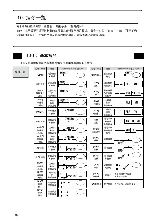
86FX 2N 可编程控制器的基本顺控指令的种类及其功能如下所示。
10-1.基本指令8710FX 系列可编程控制器的步进梯形图指令如下所示。
10-2.步进梯形图指令有黄色标记指令不支持88FX 2N 可编程控制器的应用指令如下所示。
各指令的功能以及FNC. No (指令编号)如下所示。
按《FNC. No.顺序》10-3.应用指令分类FNC No.指令符号功能D 指令P 指令备注分类FNC No.指令符号功能D 指令P 指令备注程序流程00CJ 条件跳转—○数据处理40ZRST 成批复位—○01CALL 子程序调用—○41DECO 译码—○02SRET 子程序返回——42ENCO 编码—○03IRET 中断返回——43SUM ON 位总数○○04EI 允许中断——44BON ON 的判定○○05DI 禁止中断——45MEAN 平均值○○06FEND 主程序结束——46ANS 信号报警器置位——07WDT 看门狗定时器—○47ANR 信号报警器复位—○08FOR 循环范围的开始——48SQR BIN 开方○○09NEXT 循环范围的结束——49FLT BIN 整数→2进制浮点数转换○○传送·比较10CMP 比较○○高速处理50REF 输入输出刷新—○11ZCP 区间比较○○51REFF 滤波器调整—○12MOV 传送○○52MTR 矩阵输入——13SMOV 移位—○53HSCS 比较置位(高速计数器)○—14CML 取反传送○○54HSCR 比较复位(高速计数器)○—15BMOV 成批传送—○55HSZ 区间比较(高速计数器)○—16FMOV 多点传送○○56SPD 脉冲密度——17XCH 交换○○57PLSR 脉冲输出○—18BCD BCD 转换○○58PWM 脉宽调制——19BIN BIN 转换○○59PLSR 带加减速的脉冲输出○—四则·逻辑运算20ADD BIN 加法○○便捷指令60IST 初始化状态——21SUB BIN 减法○○61SER 数据检索○○22MUL BIN 乘法○○62ABSD 凸轮顺控(绝对方式)○—23DIV BIN 除法○○63INCD 凸轮顺控(相对方式)——24INC BIN 加1○○64TTMR 示教定时器——25DEC BIN 减1○○65STMR 特殊定时器——26WAND 逻辑与○○66ALT 交替输出——27WOR 逻辑或○○67RAMP 斜坡信号——28WXOR 逻辑异或○○68ROTC 旋转工作台控制——29NEG 求补码○○69SORT 数据排列——循环移位30ROR 循环右移○○外围设备I /O70TKY 数字键输入○—31ROL 循环左移○○71HKY 16键输入○—32RCR 带进位循环右移○○72DSW 数字式开关——33RCL 带进位循环左移○○73SEGD 7段译码—○34SFTR 位右移—○74SEGL 7段码分时显示——35SFTL 位左移—○75ARWS 箭头开关——36WSFR 字右移—○76ASC ASCII 转换——37WSFL 字左移—○77PR ASCII 码打印输出——38SFWR 移位写入—○78FROM BFM 的读出○○39SFRD移位读出—○79TOBFM 的写入○○8910分类FNC No.指令符号功能D 指令P 指令备注分类FNC No.指令符号功能D 指令P 指令备注外围设备S E R80RS 串行数据传送——触点比较224LD=(S1)=(S2)○—81PRUN 8进制位传送○○225LD>(S1)>(S2)○—82ASCI HEX →ASCII 转换—○226LD<(S1)<(S2)○—83HEX ASCII →HEX 转换—○228LD<>(S1)≠(S2)○—84CCD 校验码—○229LD<=(S1)≦(S2)○—85VRRD 电位器值读取—○230LD>=(S1)≧(S2))○—86VRSC电位器刻度—○232AND=(S1)=(S2)○—87233AND>(S1)>(S2)○—88PIDPID 运算——234AND<(S1)<(S2)○—89236AND<>(S1)≠(S2)○—浮点数110ECMP 2进制浮点数比较○○237AND<=(S1)≦(S2)○—111EZCP 2进制浮点数区间比较○○238AND>=(S1)≧(S2)○—118EBCD 2进制浮点数→10进制浮点数的转换○○240OR=(S1)=(S2)○—119EBIN 10进制浮点数→2进制浮点数的转换○○241OR>(S1)>(S2)○—120EADD 2进制浮点数加法运算○○242OR<(S1)<(S2)○—121ESUB 2进制浮点数减法运算○○244OR<>(S1)≠(S2)○—122EMUL 2进制浮点数乘法运算○○245OR<=(S1)≦(S2)○—123EDIV 2进制浮点数除法运算○○246OR>=(S1)≧(S2)○—浮点数127ESQR 2进制浮点数开方运算○○129INT 2进制浮点数→BIN 整数的转换○○130SIN 2进制浮点数SIN 运算○○131COS 2进制浮点数COS 运算○○132TAN 2进制浮点数TAN 运算○○147SWAP 上下字节转换○○155ABS 读出ABS 当前值 *○—时钟运算160TCMP 时钟数据比较—○161TZCP 时钟数据区间比较—○162TADD 时钟数据加法运算—○163TSUB 时钟数据减法运算—○166TRD 时钟数据的读出—○167TWR 时钟数据的写入—○169HOUR 长时间计时*○—格雷码170GRY 格雷码的转换○○171GBIN 格雷码的逆转换○○外部设备176RD3A A/D 数据的读出 *—○177WR3A D/A 数据的写入 *—○180EXTR与三菱变频器通讯 *○○* V3.00以上追加。

FX3U·FX3UC定位指令一览
FX3U·FX3UC定位指令一览
一、原点回归指令
一、停止指令
在一般的STOP动作(减速停止)中,使用[指令的OFF]或者[正转极限标志位和反转极限标志位]。
在为了避免危险而要求立即停止的场合,请使用脉冲停止标志位。
但是,如果在定位指令的执行过程中将脉冲输出停止标志位置ON,那么脉冲输出立即停止。
因此有电机立即停止、设备损坏的危险。
二、指令执行结束标志位、指令执行异常结束标志位
三、FNC157-PLSV可变速脉冲输出
执行PLSV指令一次,则D1中脉冲量以S1的频率从D2输出。
例子:
成组位软元件的传送:
例子:
四、四则逻辑运算
DIV除法指令是将S1制定的常数或源元件中的二进制数作为被除数,除以S2指定的常数或源元件中的二进制除数,商送到指定的目标元件D 中去,榆树送到目标元件D+1 的元件中。
fx3u用户-编程手册基本应用指令说明书摘要:1.简介:了解FX3U编程手册的基本应用指令2.编程基础:熟悉编程语言和基本语法3.指令分类:概述常用指令的分类和功能4.常用指令详解:解析重要指令的应用场景和操作方法5.编程实践:结合实际案例,讲解如何在实际项目中运用FX3U编程手册6.编程技巧:分享提高编程效率和代码可读性的技巧7.常见问题与解决方案:分析常见编程问题,提供解决策略8.总结:回顾FX3U编程手册的基本应用指令,强调其在实际工作中的重要性正文:fx3u用户-编程手册基本应用指令说明书,为广大编程工作者提供了丰富的编程知识和实用技巧。
以下将针对FX3U编程手册的基本应用指令进行详细解读,以帮助读者更好地掌握与应用这些指令。
一、简介FX3U编程手册为广大用户提供了全面的基本应用指令,涵盖了逻辑运算、数据传输、数学运算、程序控制等多个方面。
为了更好地应用这些指令,我们需要对其进行深入了解。
二、编程基础在实际编程过程中,熟悉编程语言和语法是编写高质量程序的前提。
FX3U编程手册中详细介绍了编程语言和基本语法,包括数据类型、变量、常量、运算符等基本概念。
三、指令分类FX3U编程手册中的基本应用指令分为以下几类:1.逻辑运算指令:如AND、OR、NOT等。
2.数据传输指令:如MOV、CMP、PING等。
3.数学运算指令:如ADD、SUB、MUL、DIV等。
4.程序控制指令:如IF、ELSE、FOR、WHILE等。
5.数据处理指令:如SCAN、SORT、SEARCH等。
四、常用指令详解以下将详细解析一些重要指令的应用场景和操作方法:1.MOV:用于将数据从一个寄存器传输到另一个寄存器。
2.AND:用于执行逻辑与运算。
3.OR:用于执行逻辑或运算。
4.NOT:用于执行逻辑非运算。
5.IF:用于根据条件执行不同的程序分支。
6.ELSE:用于实现条件不成立时的程序分支。
7.FOR:用于循环执行一段程序。
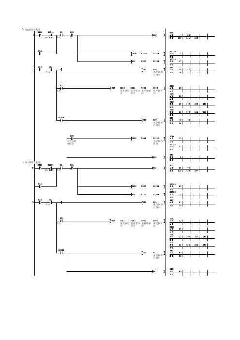
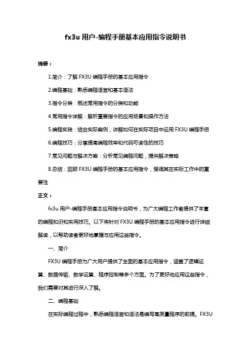
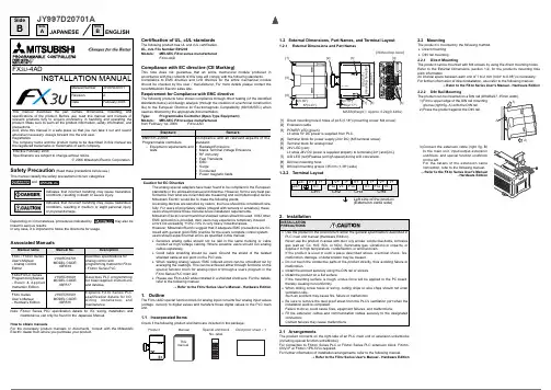
DRVI的意思一共要发送多少个脉冲数(放到D0里面),每次最多可以发送多少个脉冲(D2),,由那个输出触点发送出去(Y0),发送的是正脉冲还是负脉冲(Y3决定),链接步进电机驱动器。
DRVA的意思步进电机要移动到什么位置(位置定义为脉冲量D4),每次最多可以发送多少个脉冲(D6),,由那个输出触点发送出去(Y0),发送的是正脉冲还是负脉冲(Y3决定),链接步进电机驱动器。
ZRN指令的意思步进电机回归0点脉冲的速度(起步的时候要发多少脉冲个数D8),当接近传感器快要到达0脉冲点时的速度(快要停止时要发送多少脉冲个数D10),外部传感器的触点(X0),由那个输出触点发送出去(Y0)。
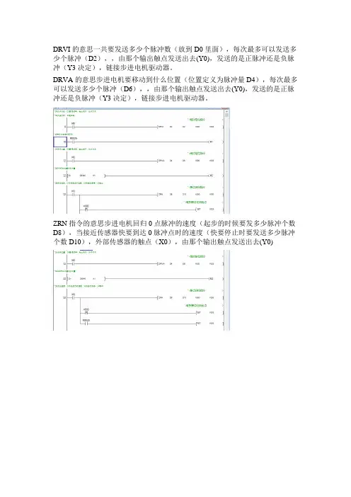
SideBSideASideBJAPANESEENGLISHJY997D20701ASafety Precaution (Read these precautions before use.)linked to serious results.In any case, it is important to follow the directions for usage.Associated ManualsNote:FX 3UC Series PLC specification details for I/O, wiring, installation, andmaintenance can only be found in the Japanese Manual.How to obtain manualsFor the necessary product manuals or documents, consult with the Mitsubishi Electric dealer from where you purchase your product.Manual name Manual No.DescriptionFX 3U / FX 3UC Series User's Manual - Analog Control EditionJY997D16701MODEL CODE:09R619Describes specifications for analog control andprogramming method for FX 3U / FX 3UC Series PLC.FX 3U /FX 3UC Series Programming Manual - B a s i c & A p p l i ed Instruction Edition JY997D16601MODEL CODE:09R517Describes PLC programming for basic/applied instructions and devices.FX 3U Series User’s Manual - Hardware EditionJY997D16501MODEL CODE:09R516Explains FX 3U Series PLC specification details for I/O,w i r i n g , i ns ta l l a t i o n , a n dmaintenance.Certification of UL, cUL standardsThe following product has UL and cUL certification.UL, cUL File Number:E95239Models:MELSEC FX 3U series manufacturedFX 3U -4ADCompliance with EC directive (CE Marking)This note does not guarantee that an entire mechanical module produced in accordance with the contents of this note will comply with the following standards.Compliance to EMC directive and LVD directive for the entire mechanical module should be checked by the user / manufacturer. For more details please contact the local Mitsubishi Electric sales site.Requirement for Compliance with EMC directiveThe following products have shown compliance through direct testing (of the identified standards below) and design analysis (through the creation of a technical construction file) to the European Directive for Electromagnetic Compatibility (89/336/EEC) when used as directed by the appropriate documentation.Type:Programmable Controller (Open Type Equipment)Models:MELSEC FX 3U series manufactured from February 1st, 2006FX 3U -4ADCaution for EC DirectiveThe analog special adapters have been found to be compliant to the European standards in the aforesaid manual and directive. However, for the very best per-formance from what are in fact delicate measuring and controlled output device Mitsubishi Electric would like to make the following points;As analog devices are sensitive by nature, their use should be considered care-fully. For users of proprietary cables (integral with sensors or actuators), these users should follow those manufacturers installation requirements.Mitsubishi Electric recommend that shielded cables should be used. If NO other EMC protection is provided, then users may experience temporary induced errors not exceeding +10%/-10% in very heavy industrial areas.However, Mitsubishi Electric suggest that if adequate EMC precautions are fol-lowed with general good EMC practice for the users complete control system, users should expect normal errors as specified in this manual.•Sensitive analog cable should not be laid in the same trunking or cable conduit as high voltage cabling. Where possible users should run analog cables separately.•Good cable shielding should be used. Ground the shield of the twisted shielded cable at one point on the PLC side.•When reading analog values, EMC induced errors can be smoothed out by averaging the readings. This can be achieved either through functions on the special function block for analog input or through a users program in the FX 3U Series PLC main unit.•Please use FX 3U -4AD while installed in a shielded enclosure. For the details,refer to the following manual.→ Refer to the FX 3U Series User's Manual - Hardware Edition1.OutlineThe FX 3U -4AD special function block for analog input converts four analog input values (voltage, current) to digital values and transfers those digital values to the PLC main unit.1.1Incorporated ItemsCheck if the following product and items are included in the package:StandardRemarkEN61131-2:2003Programmable controllers-Equipment requirements and testsCompliance with all relevant aspects of the standard.•Radiated Emissions•Mains Terminal Voltage Emissions •RF immunity •Fast Transients •ESD •Surge•Conducted•Power magnetic fields1.2External Dimensions, Part Names, and Terminal Layout1.2.1External Dimensions and Part Names1.2.2Terminal Layout2.Installation2.1ArrangementsThe product connects on the right side of an PLC main unit or extension units/blocks (including special function units/blocks).For connection to FX 3UC Series PLC or FX 2NC Series PLC extension block, FX 2NC -CNV-IF or FX 3UC -1PS-5V is required.For further information of installation arrangements, refer to the following manual.→ Refer to the FX 3U Series User's Manual - Hardware Edition[1]Direct mounting hole:2 holes of φ4.5 (0.18") (mounting screw: M4 screw)[2]Extension cable[3]POWER LED (green):Lit while 5V DC power is supplied from PLC.[4]Terminal block for power supply (24V DC) (M3 terminal screw)[5]Terminal block for analog input [6]24V LED (red):Lit while 24V DC power is supplied properly to terminals [24+] and [24-].[7]A/D LED (red):Flashes (at high speed) during A/D conversion. [8]DIN rail mounting hook[9]DIN rail mounting groove (35 mm (1.38") wide)INSTALLATION PRECAUTIONS•Use the product in the environment within the general specifications described in PLC main unit manual (Hardware Edition).Never use the product in areas with dust, oily smoke, conductive dusts, corrosive gas (salt air, Cl 2, H 2S, SO 2, or NO 2), flammable gas, vibrations or impacts, or expose it to high temperature, condensation, or wind and rain.If the product is used in such a place described above, electrical shock, fire,malfunction, damage, or deterioration may be caused.•Do not touch the conductive parts of the product directly, thus avoiding failure or malfunction.•Install the product securely using the DIN rail or screws.•Install the product on a flat surface.If the mounting surface is rough, undue force will be applied to the PC board,thereby causing nonconformity.•When drilling screw holes or wiring, cutting chips or wire chips should not enter ventilation slits.Such an accident may cause fire, failure or malfunction.•Be sure to remove the dust proof sheet from the PLC's ventilation port when the installation work is completed.Failure to do so could cause fires, equipment failures, and malfunctions.•Fit the extension cables and communication cables securely to the designated connectors.Contact failures may cause malfunctions.2.2MountingThe product is mounted by the following method. •Direct mounting •DIN rail mounting2.2.1Direct MountingThe product can be mounted with M4 screws by using the direct mounting holes.Refer to the External Dimensions (section 1.2) for the product’s mounting hole pitch information.An interval space between each unit of 1 to 2 mm (0.04" to 0.08") is necessary. For further information of direct installation, also refer to the following manual.→ Refer to the FX 3U Series User's Manual - Hardware Edition2.2.2DIN Rail MountingThe product can be mounted on a DIN rail (DIN46227, 35mm width).1)Fit the upper edge of the DIN rail mounting groove (right fig. A) onto the DIN rail. 2)Press the product against the DIN rail.3)on the left.→ Refer to the FX 3U FX 3U -4ADINSTALLATION MANUALThis manual describes the part names, dimensions, mounting, and specifications of the product. Before use, read this manual and manuals of relevant products fully to acquire proficiency in handling and operating the product. Make sure to learn all the product information, safety information, and precautions.And, store this manual in a safe place so that you can take it out and read it whenever necessary. Always forward it to the end user.RegistrationThe company name and the product name to be described in this manual are the registered trademarks or trademarks of each company.Effective February 2006Specifications are subject to change without notice.© 2006 Mitsubishi Electric CorporationManual Number JY997D20701Revision ADateFebruary 20063.Wiring*1For FX 3U Series PLC (AC power type), the 24V DC service power supply is also4.4Performance Specification4.5Input characteristicsThe input characteristics in each input mode are as follows.For the details of the input characteristics, refer to the following manual.→ Refer to the FX 3U / FX 3UC Series User’s Manual- Analog Control EditionSideBSideASideBJAPANESEENGLISHJY997D20701ASafety Precaution (Read these precautions before use.)This manual classify the safety precautions into two categories:linked to serious results.In any case, it is important to follow the directions for usage.Associated ManualsNote:FX 3UC Series PLC specification details for I/O, wiring, installation, andmaintenance can only be found in the Japanese Manual.How to obtain manualsFor the necessary product manuals or documents, consult with the Mitsubishi Electric dealer from where you purchase your product.Manual name Manual No.DescriptionFX 3U / FX 3UC Series User's Manual - Analog Control EditionJY997D16701MODEL CODE:09R619Describes specifications for analog control andprogramming method for FX 3U / FX 3UC Series PLC.FX 3U /FX 3UC Series Programming Manual - B a s i c & A p p l i ed Instruction Edition JY997D16601MODEL CODE:09R517Describes PLC programming for basic/applied instructions and devices.FX 3U Series User’s Manual - Hardware EditionJY997D16501MODEL CODE:09R516Explains FX 3U Series PLC specification details for I/O,w i r i n g , i ns ta l l a t i o n , a n dmaintenance.Certification of UL, cUL standardsThe following product has UL and cUL certification.UL, cUL File Number:E95239Models:MELSEC FX 3U series manufacturedFX 3U -4ADCompliance with EC directive (CE Marking)This note does not guarantee that an entire mechanical module produced in accordance with the contents of this note will comply with the following standards.Compliance to EMC directive and LVD directive for the entire mechanical module should be checked by the user / manufacturer. For more details please contact the local Mitsubishi Electric sales site.Requirement for Compliance with EMC directiveThe following products have shown compliance through direct testing (of the identified standards below) and design analysis (through the creation of a technical construction file) to the European Directive for Electromagnetic Compatibility (89/336/EEC) when used as directed by the appropriate documentation.Type:Programmable Controller (Open Type Equipment)Models:MELSEC FX 3U series manufactured from February 1st, 2006FX 3U -4ADCaution for EC DirectiveThe analog special adapters have been found to be compliant to the European standards in the aforesaid manual and directive. However, for the very best per-formance from what are in fact delicate measuring and controlled output device Mitsubishi Electric would like to make the following points;As analog devices are sensitive by nature, their use should be considered care-fully. For users of proprietary cables (integral with sensors or actuators), these users should follow those manufacturers installation requirements.Mitsubishi Electric recommend that shielded cables should be used. If NO other EMC protection is provided, then users may experience temporary induced errors not exceeding +10%/-10% in very heavy industrial areas.However, Mitsubishi Electric suggest that if adequate EMC precautions are fol-lowed with general good EMC practice for the users complete control system, users should expect normal errors as specified in this manual.•Sensitive analog cable should not be laid in the same trunking or cable conduit as high voltage cabling. Where possible users should run analog cables separately.•Good cable shielding should be used. Ground the shield of the twisted shielded cable at one point on the PLC side.•When reading analog values, EMC induced errors can be smoothed out by averaging the readings. This can be achieved either through functions on the special function block for analog input or through a users program in the FX 3U Series PLC main unit.•Please use FX 3U -4AD while installed in a shielded enclosure. For the details,refer to the following manual.→ Refer to the FX 3U Series User's Manual - Hardware Edition1.OutlineThe FX 3U -4AD special function block for analog input converts four analog input values (voltage, current) to digital values and transfers those digital values to the PLC main unit.1.1Incorporated ItemsCheck if the following product and items are included in the package:StandardRemarkEN61131-2:2003Programmable controllers-Equipment requirements and testsCompliance with all relevant aspects of the standard.•Radiated Emissions•Mains Terminal Voltage Emissions •RF immunity •Fast Transients •ESD •Surge•Conducted•Power magnetic fields1.2External Dimensions, Part Names, and Terminal Layout1.2.1External Dimensions and Part Names1.2.2Terminal Layout2.Installation2.1ArrangementsThe product connects on the right side of an PLC main unit or extension units/blocks (including special function units/blocks).For connection to FX 3UC Series PLC or FX 2NC Series PLC extension block, FX 2NC -CNV-IF or FX 3UC -1PS-5V is required.For further information of installation arrangements, refer to the following manual.→ Refer to the FX 3U Series User's Manual - Hardware Edition[1]Direct mounting hole:2 holes of φ4.5 (0.18") (mounting screw: M4 screw)[2]Extension cable[3]POWER LED (green):Lit while 5V DC power is supplied from PLC.[4]Terminal block for power supply (24V DC) (M3 terminal screw)[5]Terminal block for analog input [6]24V LED (red):Lit while 24V DC power is supplied properly to terminals [24+] and [24-].[7]A/D LED (red):Flashes (at high speed) during A/D conversion. [8]DIN rail mounting hook[9]DIN rail mounting groove (35 mm (1.38") wide)INSTALLATION PRECAUTIONS•Use the product in the environment within the general specifications described in PLC main unit manual (Hardware Edition).Never use the product in areas with dust, oily smoke, conductive dusts, corrosive gas (salt air, Cl 2, H 2S, SO 2, or NO 2), flammable gas, vibrations or impacts, or expose it to high temperature, condensation, or wind and rain.If the product is used in such a place described above, electrical shock, fire,malfunction, damage, or deterioration may be caused.•Do not touch the conductive parts of the product directly, thus avoiding failure or malfunction.•Install the product securely using the DIN rail or screws.•Install the product on a flat surface.If the mounting surface is rough, undue force will be applied to the PC board,thereby causing nonconformity.•When drilling screw holes or wiring, cutting chips or wire chips should not enter ventilation slits.Such an accident may cause fire, failure or malfunction.•Be sure to remove the dust proof sheet from the PLC's ventilation port when the installation work is completed.Failure to do so could cause fires, equipment failures, and malfunctions.•Fit the extension cables and communication cables securely to the designated connectors.Contact failures may cause malfunctions.2.2MountingThe product is mounted by the following method. •Direct mounting •DIN rail mounting2.2.1Direct MountingThe product can be mounted with M4 screws by using the direct mounting holes.Refer to the External Dimensions (section 1.2) for the product’s mounting hole pitch information.An interval space between each unit of 1 to 2 mm (0.04" to 0.08") is necessary. For further information of direct installation, also refer to the following manual.→ Refer to the FX 3U Series User's Manual - Hardware Edition2.2.2DIN Rail MountingThe product can be mounted on a DIN rail (DIN46227, 35mm width).1)Fit the upper edge of the DIN rail mounting groove (right fig. A) onto the DIN rail. 2)Press the product against the DIN rail.3)on the left.→ Refer to the FX 3U3.Wiring3.1Applicable Cable and Terminal Tightening TorqueThe size of the terminal screws is M3.The end disposal of the cable shows below.Tighten the terminal to a torque of 0.5N m to 0.8N m.•When one wire is connected to one terminal•When two wires are connected to one terminal3.2Power Supply WiringFor the power supply wiring, refer to the following manual.→ Refer to the FX 3U / FX 3UC Series User’s Manual- Analog Control Edition3.3Wiring of Analog Input→ For the terminal layout, refer to Subsection 1.2.2*1For FX 3U Series PLC (AC power type), the 24V DC service power supply is alsoavailable. *2terminal.*3Use a 2-core twisted shield wire for analog input line, and separate it from otherpower lines or inductive lines.*4For the current input, short-circuit the [V+] terminal and the [I+] terminal. *5If there is voltage ripple in the input voltage or there is noise in the externalwiring, connect a capacitor of approximately 0.1 to 0.47µF 25 V.3.4GroundingGrounding should be performed as stated below.•The grounding resistance should be 100Ω or less.•Independent grounding should be performed for best results.When independent grounding is not performed, perform "shared grounding"of the following figure.→ For details, refer to the FX 3U Series User's Manual- Hardware Edition.•The grounding wire size should be AWG 14 (2 mm 2).•The grounding point should be close to the PLC, and all grounding wire should be as short as possible.4.Specification4.1Applicable PLCThe version number can be checked by monitoring D8001 as the last three digits indicate it.4.2General SpecificationThe items other than the following are equivalent to those of the PLC main unit. For other general specifications, refer to the manual of the PLC main unit.→ For details, refer to the FX 3U Series User's Manual- Hardware Edition.4.3Power Supply SpecificationSTARTUP ANDMAINTENANCE PRECAUTIONS•Do not disassemble or modify the unit.Doing so may cause failure, malfunction or fire.* For repair, contact your local Mitsubishi Electric distributor.•Do not drop the product or do not exert strong impact, doing so may cause damage.DISPOSAL PRECAUTIONS•Please contact a company certified in the disposal of electronic waste forenvironmentally safe recycling and disposal of your device.TRANSPORT ANDSTORAGE PRECAUTIONS•During transportation avoid any impact as the product is a precision instrument.Check the operation of the product after transportation.Model name ApplicabilityFX 3U Series PLC Ver. 2.20 (from the first product) and laterFX 3UC Series PLCVer. 1.30 (from the product manufactured in August, 2004 with SER No. 48) and laterItemSpecificationDielectric withstandvoltage500V AC for one minuteConforming to JEM-1021Between all terminals and ground terminal of PLCmain unitInsulation resistance 5M Ω or more by 500V DC megger Item SpecificationA/D conversion circuit driving power 24V DC ±10%, 90mA for 24V DCConnect a 24V DC power supply to the terminal block.CPU driving power5V DC, 110mA5V DC power is supplied internally from the main unit.4.4Performance Specification*1Change the offset and gain values to change the input characteristics. However,the resolution doesn’t change even when the offset and gain values change.When the analog value direct indication is enabled in the input mode 2, 5, or 8,the offset value and the gain value don’t change. *2The offset and the gain should satisfy the following condition:1V ≤ (Gain - Offset)*3The offset and the gain should satisfy the following condition:3 mA ≤ (Gain - Offset) ≤ 30 mA*4The input characteristics vary depending on the input mode to be used.For the details of the input characteristics, refer to the following manual.→ Refer to the FX 3U / FX 3UC Series User’s Manual- Analog Control Edition4.5Input characteristicsThe input characteristics in each input mode are as follows.For the details of the input characteristics, refer to the following manual.→ Refer to the FX 3U / FX 3UC Series User’s Manual- Analog Control EditionInput mode Input modeAnalog inputrange Digital outputrange 0Voltage input mode -10 to +10V -32000 to +320001Voltage input mode-10 to +10V -4000 to +40002Voltage input modeAnalog value direct indication -10 to +10V -10000 to +100003Current input mode 4 to 20mA 0 to 160004Current input mode4 to 20mA 0 to 40005Current input modeAnalog value direct indication 4 to 20mA 4000 to 200006Current input mode -20 to +20mA -16000 to +160007Current input mode-20 to +20mA -4000 to +40008Current input modeAnalog value direct indication-20 to +20mA-20000 to +20000FX 3U -4ADINSTALLATION MANUALThis manual describes the part names, dimensions, mounting, and specifications of the product. Before use, read this manual and manuals of relevant products fully to acquire proficiency in handling and operating the product. Make sure to learn all the product information, safety information, and precautions.And, store this manual in a safe place so that you can take it out and read it whenever necessary. Always forward it to the end user.RegistrationThe company name and the product name to be described in this manual are the registered trademarks or trademarks of each company.Effective February 2006Specifications are subject to change without notice.© 2006 Mitsubishi Electric CorporationManual Number JY997D20701Revision ADateFebruary 2006。
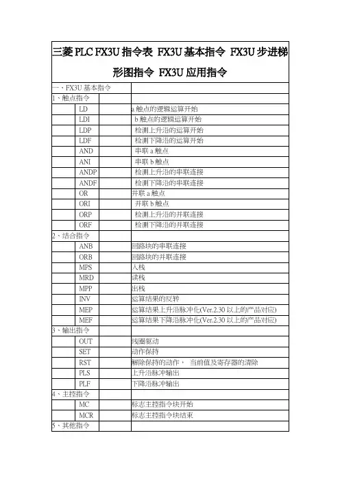
第5章三菱FX3U系列PLC的基本指令系统一、LD、LDI、OUT指令二、AND、ANI指令三、OR、ORI指令四、ANB、ORB指令五、LDP、LDF、ANDP、ANDF、ORP、ORF指令六、MPS、MRD、MPP指令5.1FX3U系列PLC 的基本指令七、MC、MCR指令八、SET、RST指令九、PLS、PLF指令十、INV指令指令十一、MEP、MEF指令十二、NOP、END指令5.1.1触点指令及线圈输出指令1、LD、LDI、OUT指令指令的作用LD(LoaD):取指令,常开触点与母线连接。
LDI(LoaDInverse):取反指令,常闭触点与母线连接。
OUT:驱动线圈的输出指令。
编程元件LD:LDI:X、Y、M、S、T、COUT:Y、M、S、T、CLD、LDI、OUT指令的功能、电路表示、操作元件、所占的程序步符号、名称功能电路表示及操作元件程序步LD(取)(load)常开触点逻辑运算起始1LDI(取反)(loadinverse)常闭触点逻辑运算起始1OUT(输出)线圈驱动Y、M,1(特殊辅助继电器M ,2)T,3;C,3~5LD、LDI、OUT用法示例指令表程序步序指令地址梯形图注意事项LD、LDI用于将触点接到母线上。
LD、LDI还与块操作指令ANB、ORB相配合,用于分支电路的起点。
OUT不能用于X;并联输出OUT指令可连续使用任意次。
OUT指令用于T和C,其后须跟常数K,K为延时时间或计数次数。
常数K的设定,如下:定时器、计数器K的设定范围实际的设定值步数1ms定时器1~32,7670.001~32.767秒310ms定时器1~32,7670.01~327.67秒3100ms定时器0.1~3276.7秒16位计数器1~32,767同左332位计数器-2,147,483,648~+2,147,483,647同左5双线圈输出在用户程序中,同一个编程元件的线圈使用了两次或多次,称为双线圈输出。
fx3u用户-编程手册基本应用指令说明书FX3U系列PLC(可编程逻辑控制器)是一种常用的自动化控制设备,广泛应用于工业生产线等领域。
本文是FX3U用户编程手册的基本应用指令说明书,旨在帮助用户更好地理解和使用FX3U PLC。
以下是对各个指令进行详细说明。
1. LD指令:LD指令用于将数据从指定的地址加载到寄存器中。
它的基本语法为LD A, B,其中A表示目标寄存器,B表示源地址。
例如,LD D100, M10将把M10地址处的数据加载到D100寄存器中。
2. AND指令:AND指令用于执行逻辑与操作。
它的基本语法为AND A, B,其中A和B可以是寄存器或地址。
例如,AND Y0, X1将执行Y0寄存器与X1寄存器的逻辑与操作。
3. OR指令:OR指令用于执行逻辑或操作。
它的基本语法为OR A, B,其中A和B可以是寄存器或地址。
例如,OR Y0, X1将执行Y0寄存器与X1寄存器的逻辑或操作。
4. OUT指令:OUT指令用于将数据从寄存器输出到指定的地址。
它的基本语法为OUT A, B,其中A表示源寄存器,B表示目标地址。
例如,OUT D100, Y0将把D100寄存器中的数据输出到Y0地址处。
5. IN指令:IN指令用于从外部设备(如传感器)读取数据并保存到寄存器中。
它的基本语法为IN A, B,其中A表示目标寄存器,B表示外部设备的地址。
例如,IN D100, X0将从X0地址处读取数据并保存到D100寄存器中。
6. TIM指令:TIM指令用于设定定时器的时间间隔。
它的基本语法为TIM A, B,其中A表示定时器的编号,B表示时间间隔。
例如,TIM T0, 100将设置T0定时器的时间间隔为100毫秒。
7. CMP指令:CMP指令用于比较两个数据的大小。
它的基本语法为CMP A, B,其中A和B可以是寄存器或地址。
例如,CMP D100,D200将比较D100和D200寄存器中的数据大小。
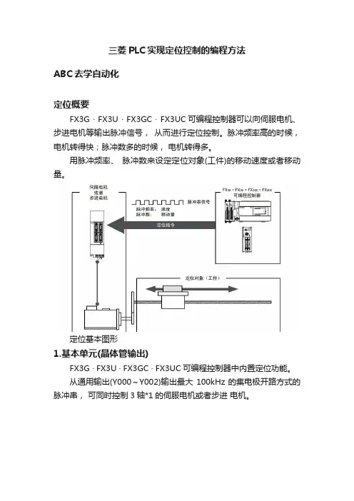
三菱PLC实现定位控制的编程方法ABC去学自动化定位概要FX3G · FX3U · FX3GC · FX3UC可编程控制器可以向伺服电机、步进电机等输出脉冲信号,从而进行定位控制。
脉冲频率高的时候,电机转得快;脉冲数多的时候,电机转得多。
用脉冲频率、脉冲数来设定定位对象(工件)的移动速度或者移动量。
定位基本图形1.基本单元(晶体管输出)FX3G · FX3U · FX3GC · FX3UC可编程控制器中内置定位功能。
从通用输出(Y000~Y002)输出最大100kHz的集电极开路方式的脉冲串,可同时控制3轴*1的伺服电机或者步进电机。
2. 特殊适配器特殊适配器使用FX3U可编程控制器内置的定位功能,输出最大200kHz的差动线性驱动方式的脉冲串,可同时控制4轴的伺服电机或者步进电机。
FX3U可编程控制器最多可以连接2台高速输出特殊适配器(FX3U-2HSY-ADP)。
· 第1台FX3U-2HSY-ADP使用Y000、 Y004和Y001、 Y005。
· 第2台FX3U-2HSY-ADP使用Y002、 Y006和Y003、 Y007。
3.特殊功能模块/单元FX3U · FX3UC可编程控制器可以连接特殊功能模块/单元,进行定位控制。
此外,特殊功能单元也可以独立进行定位控制。
1). FX3U可编程控制器的构成FX3U可编程控制器中最多可以连接8台特殊功能模块/单元。
2). FX3UC可编程控制器的构成FX3UC可编程控制器中最多可以连接8台*1特殊功能模块/单元。
连接特殊功能模块/单元时,一定需要FX2NC-CNV-IF或者FX3UC-1PS-5V。
*1. 与FX3UC-32MT-LT(-2)连接时,最多可以连接7台。
*2. 与FX3UC-32MT-LT(-2)连接时,从No.1开始。
3). 单独运行(FX2N-10GM, FX2N-20GM)特殊功能单元(FX2N-10GM、 FX2N-20GM)可以不连接在可编程控制器上,而独立运行。
干货:三菱FX3U控制伺服的高速脉冲指令,跟我一起做,马上就会三菱FX3U做为一款入门级PLC,应用很广泛,其实学习PLC就几点,开关量的输入、输出,就是我们平常所说的IO、伺服(或者步进电机)的控制、Modbus通信、模拟量输入输出,掌握了这些,基本可以做80%的项目了,小编今天主要来和大家说一下伺服电机(或者步进电机)的控制方法。
其实伺服电机就是高级一点的步进,其自带编码器,驱动器功能更加强大,支持位置模式、速度模式和转矩模式三种类型,因为伺服电机可以精确定位,所以通常我们用到的是位置模式。
位置模式需要PLC发送高速脉冲串给伺服驱动器,伺服驱动器再驱动伺服电机按照一定的角度和速度来旋转,从而达到位置控制的模式三菱FX3U这款PLC控制伺服电机有两种方法,一种是高速脉冲模式,一种是定位模式,其指令是不一样的,同时,FX3U只支持三路高速脉冲的发送,分别是Y0、Y1、Y2,所以最多只能控制三台伺服电机,如果想控制超三台伺服电机,可以选择加装定位模块或者几台PLC组网来实现。
一、高速脉冲模式1、PLSY指令PLSY是高速脉冲输出指令,可以指定Y0、Y1或者Y2发送高速脉冲,其指令格式如下如上图所示,分别是16位高速脉冲输出和32位高速脉冲输出,16位高速脉冲输出可以发送最大频率为32767的数据,而32位高速脉冲输出可以发送最大频率为200,000Hz的脉冲串,各位同学可以根据实际需要进行选择,不过这里小编建议大家养成一个好习惯,就是坚持用32位运算进行程序处理,可以有效防止程序溢出。
熟悉了相关指令,我们看下详细用法。
比如我们想接通M0的同时,让Y0输出频率为10000,数量为25000的脉冲串,那么就这样来写程序其中:频率为每秒钟发送的脉冲数,表示到伺服电机就是速度发送脉冲数即为一共发送多少个脉冲给驱动器,转换到伺服电机就是走过的距离或者角度Y0为输出通道,接线到驱动侧的高速脉冲输入点。
这里M0只要保持接通,就会以当前速度发送25000个脉冲,中间如果M0断开,则停止发送脉冲,再次接通M0则重新发送25000个脉冲直到完成。
三菱FX3U系列伺服定位指令全面详解,附带程序案例!BFH一、PLC定位及伺服控制系统介绍通过PLC给伺服驱动器发驱动脉冲,通过改变脉冲频率来控制移动速度,通过改变脉冲数量来改变移动量,控制步进电机移动方向。
伺服驱动器是执行机构,在接收到PLC发来的信号,控制电机来运动,通过位置编码器精准定位。
1、定位控制基本单元通过一个FX3U的CPU就可以带三个轴的伺服驱动器。
PLC的脉冲输出端是固定的,Y0、Y1、Y2。
具体是否具备脉冲输出可看模块的手册。
其余的Y可以作为方向的输出端。
输出的最大脉冲频率为100KHz。
2、FX3U PLC特殊适配器扩展单元展开剩余92%基本单元的脉冲输出Y不起作用,只能用特殊适配器扩展单元的输入Y来输出脉冲。
3、PLC输入端内部电路(漏型输入)4、PLC输出端内部电路Y0可以提供脉冲频率和脉冲数量。
利用Y4输出方向。
由定位指令来实现,不需要单独编程Y4.二、FX3U-PLC定位控制指令(一)、原点回归指令:ZRN首先以S1的速度快速运动,当到近点S3后切换到爬行速度S2,D为输出。
只能在原点的正方向才能使用原点回归指令,在反向是不能使用ZRN指令的。
1、原点回归指令ZRN运行过程2、原点回归指令ZRN,速度变化过程及清零信号说明1)Y0脉冲输出端的清零信号选择(1)M8341=ON;清零信号有效M8464=OFF;清零信号输出端固定有效Y4--清零信号固定输出端。
2)Y0脉冲输出端的清零信号选择(2)M8341=ON;清零信号有效M8464=ON;清零信号输出指定有效D8464--清零信号指定寄存器。
例:上图中当执行条件满足,将M8341=1,M8464=1,将Y20送到D8464.注意:若设置H0028,对应的Y028,由于没有Y028,则出现运算错误。
3)清零信号输出端固定(与脉冲输出端一致性)4)清零信号输出端可指定(可任意选择)3、定位指令的最高速度设定最高速度限定了PLC输出最高脉冲频率,为定位指令的上线频率。
8.程序流程-FNC00~FNC09
9.传送·比较-FNC10~FNC19
10.四则逻辑运算-FNC20~FNC29
11.循环·移位-FNC30~FNC39
13.高速处理-FNC50~FNC59
15.外部设备I/O-FNC70~FNC79
16.外部设备SER(选件设备)-FNC80~FNC89
17.数据传送2-FNC100~FNC109
18.浮点数运算-FNC110~FNC139
19.数据处理2-FNC140~FNC149
20.定位控制-FNC150~FNC159
21.时钟运算-FNC160~FNC169
22.外部设备-FNC170~FNC179
23.1指令替换对照表
24.其他指令FNC181~FNC189
25.数据块处理-FNC190~FNC199
26.字符串控制-FNC200~FNC209
27.数据处理3-FNC210~FNC219
28.触点比较指令-FNC220~FNC249
29.数据表处理-FNC250~FNC269
应用指令说明8-33摘自:《FX3G ·FX3U ·FX3UC 系列微型可编程控制器编程手册(基本·应用指令说明书)》
30.外部设备通信(变频器通信)-FNC 270~FNC 274
31.数据传送3-FNC 275~FNC 279
32.高速处理2-FNC 280~FNC 289
33.扩展文件寄存器控制-FNC 290~FNC 299
以上内容摘自:《FX3G ·FX3U ·FX3UC 系列微型可编程控制器编程手册(基本·应用指令说明书)》。
fx3u定位控制实例FX3U是三菱电机推出的一款高性能PLC,可广泛应用于自动化控制系统中。
其中,定位控制是FX3U的一项重要功能,可以实现对机械装置的精确定位和运动控制。
本文将以FX3U定位控制实例为主题,介绍其原理和应用。
一、定位控制的原理定位控制是通过控制电机的运动,使得被控制物体精确移动到预定位置的过程。
在FX3U中,定位控制主要依靠PLC的高速计数器和脉冲输出功能来实现。
需要通过高速计数器来接收外部脉冲信号,通常是由编码器或脉冲发生器产生的。
高速计数器能够精确地计算脉冲的数量,从而确定电机的位置。
然后,PLC会根据设定的目标位置和当前位置之间的差值,计算出控制电机需要输出的脉冲数量。
接下来,FX3U通过脉冲输出功能将计算得到的脉冲信号发送给电机驱动器,驱动器会根据接收到的脉冲信号控制电机的转动角度和速度。
通过连续输出脉冲信号,电机可以逐步移动到目标位置,实现定位控制。
二、FX3U定位控制的应用FX3U的定位控制功能广泛应用于各种自动化设备和生产线中,以下以一个简单的装配机器人为例,介绍FX3U定位控制的应用过程。
装配机器人通常由多个电机和传感器组成,通过定位控制实现对零部件的精确装配。
首先,需要将机器人的各个关节与电机相连,并安装编码器用于测量电机的转动角度。
然后,通过编程设置FX3U 的高速计数器和脉冲输出功能,使其能够接收编码器的脉冲信号并控制电机的运动。
在装配过程中,传感器可以感知到待装配零部件的位置和状态,并将信号传输给FX3U。
FX3U根据传感器的信号确定待装配零部件的位置,然后计算出电机需要输出的脉冲数量。
通过控制电机的输出脉冲信号,机器人的各个关节可以精确地移动到目标位置,完成零部件的装配。
除了装配机器人,FX3U定位控制还可以应用于印刷机械、包装设备、数控机床等领域。
在印刷机械中,通过定位控制可以实现印刷品的对位精确度,提高印刷质量。
在包装设备中,定位控制可以使得包装物料准确地进入包装盒中,提高生产效率。
三菱FX系列plc指令集锦1、LD 取一常开触点指令2、LDI 取一常闭触点指令3、AND 串联一常开触点4、ANI 串联一常闭触点5、OR 并一常开触点6、ORI 并一常闭7、ANB 并联回路的“与”运算8、ORB 并联回路的“或”运算9、MPS 累加器结果的进栈堆10、MRD 读取栈内容11、MPP 堆栈移出内容12、PLS 上升沿输出13、PLF 下降沿输出14、LDP 上升沿读入累加器15、LDF 下降沿读入累加器16、ANDP 累加器内容与上升沿“与”运算17、ANDF 累加器内容与下降沿“与运算18、ORP 累加器内容与上升沿“或”运算19、ORF 累加器内容与下降沿“或”运算20、MC 生产主控母线(操作数Y、M)21、MCR 生产主控母线复位指令22、示教式定时设定的应用制定功能指令TTMR(FNC64)注释:“K2”常数0—2设定定时设定值与按键输入时间的比例1)、当K=0时,定时设定与按键输入比例为1:12)、当K=1时,定时设定与按键输入比例为1:103)、当K=2时,定时设定与按键输入比例为1:100TTMR实际改变的是数据寄存器的存储数据,故需要进行示教式设定的定时器必须用数据寄存器D来设定时间。
(精度比较差)23、任意频率的时钟生成M8011(10Ms)M8012(100Ms)M8013(1S)M8014(60S)任意周期时钟脉冲信号可利用STMR指令的特性,通过以下程序生成。
24、高速比较指令(DHSZ)25、高速置位/复位指令(DHSCS/DHSCR)FNC53/FNC54用于计数器的比较与输出的直接控制注释:高速计数器C241为带复位输入(X1)的单相高速输入计数器,使用DHSCS后,只要计数器值达到1000后,y0置1(不受PLC时间的限制),而使用DHSCR后,只要计数值到达2000,就可以使Y0置为0。
26、高速比较指令(DHSZ) FNC 55注释:K1000为比较下限K2000为比较上限27、速度测量(SPD) FNC56(脉冲密度指令)可以计算单位时间内的输入脉冲数,可用于以位置脉冲形式输出的机械装置速度的实时测量。
FX3U·FX3UC定位指令一览
一、原点回归指令
一、停止指令
在一般的STOP动作(减速停止)中,使用[指令的OFF]或者[正转极限标志位和反转极限标志位]。
在为了避免危险而要求立即停止的场合,请使用脉冲停止标志位。
但是,如果在定位指令的执行过程中将脉冲输出停止标志位置ON,那么脉冲输出立即停止。
因此有电机立即停止、设备损坏的危险。
二、指令执行结束标志位、指令执行异常结束标志位
三、FNC157-PLSV可变速脉冲输出
执行PLSV指令一次,则D1中脉冲量以S1的频率从D2输出。
四、传送指令
将软元件的内容传送到其他的软元件中的指令。
例子:
成组位软元件的传送:
例子:
五、四则逻辑运算
DIV除法指令是将S1制定的常数或源元件中的二进制数作为被除数,除以S2指定的常数或源元件中的二进制除数,商送到指定的目标元件D中去,榆树送到目标元件D+1 的元件中。