ASTM--D380-1994
- 格式:pdf
- 大小:184.23 KB
- 文档页数:10
ASTM美國試驗與材料協會標準(紡織部分)標準代號標準名稱ASTM D1059-2001基於短長度樣品的紗線支數試驗方法ASTM D1060-1996為測定淨毛纖維百分率從成包原毛中心取樣的標準操作規程ASTM D1113a-1990洗淨羊毛中植物性物質和其它鹼性不溶雜質的標準測試方法ASTM D1117-2001無紡織物評價的標準指南ASTM D1230-1994服裝紡織品的易燃性的標準測試方法ASTM D1230-1994服裝紡織品的易燃性的標準測試方法ASTM D123-2002與紡織品相關的標準術語ASTM D1234-1985含脂羊毛的手扯長度的取樣和試驗方法ASTM D1244-1998紗線結構的名稱與符號ASTM D1282-1996用氣流阻力表示羊毛毛條,生條和洗淨羊毛的平均纖維直經的標準測試方法ASTM D1283-1985羊毛堿溶性的測試方法ASTM D1294a-19951英寸(25.4毫米)長度的羊毛纖維束拉伸強度和斷裂強度的標準試驗方法ASTM D1334-1996原毛毛含量的標準試驗方法.商業尺度ASTM D1422-1999退撚加撚法測定單細紗撚數的標準試驗方法ASTM D1423-2002直接計數法測定紗線撚數的標準試驗方法ASTM D1424-1996埃爾曼多夫落錘儀測定機織物抗撕裂的標準試驗方法ASTM D1425-1996用電容測試設備測定紗線條幹不勻度的標準試驗方法ASTM D1440-1996棉纖維長度和長度分佈的標準試驗方法(列陣法)ASTM D1441-2000試驗用棉纖維取樣的標準操作規程ASTM D1442-2000棉纖維成熟度的標準試驗方法(燒鹼膨脹與偏振光法)ASTM D1445-1995棉纖維的斷裂強度和延伸率的標準試驗方法(扁纖維束法)ASTM D1447-2000用纖維照影機測量法測定棉纖維的長度和長度均勻度的標準試驗方法ASTM D1448-1997棉纖維的馬克隆尼讀數的標準試驗方法ASTM D1464-1990棉花染色差異性的標準試驗方法ASTM D1518-1985紡織材料的熱傳導的標準試驗方法ASTM D1571-1995石棉布的標準規範ASTM D1575-1990洗淨羊毛及生條中羊毛纖維長度的測試方法ASTM D1576-1990用爐烘乾法測定羊毛內水分的試驗方法ASTM D1578-1993絞紗形式下紗線的斷裂強度的試驗方法ASTM D1684-1996顏色分級用棉分級室的照明的標準操作規程ASTM D1770-1994羊毛條中毛結,植物性物質與有色纖維含量標準測試方法ASTM D1776-1998試驗用調濕織物ASTM D1777-1996測量紡織材料的厚度的標準試驗方法ASTM D1909-1996紡織纖維商品回潮率標準表ASTM D1913-2000服裝革抗濕性的標準試驗方法(噴霧法)ASTM D1987-1995土工織物或泥土/土工織物的生物阻塞的標準試驗方法ASTM D204-2002縫紉線的標準試驗方法ASTM D2052-2001拉鍊耐乾洗色牢度的測試方法ASTM D2052-2001拉鍊耐乾洗色牢度的測試方法ASTM D2053-1999拉鍊耐光照色牢度的試驗方法ASTM D2053-1999拉鍊耐光照色牢度的試驗方法ASTM D2062-1987拉鍊可用性的試驗方法ASTM D2062-1987拉鍊可用性的試驗方法ASTM D2118-1996羊毛及其製品中標準水份含量的確定ASTM D2130-1990顯微投影法測定羊毛和其它動物纖維直徑的標準試驗方法ASTM D2165-1994羊毛及類似動物纖維的水萃取物pH值的標準測試方法ASTM D2252-1996各類阿爾帕卡毛細度的標準規範ASTM D2257-1998紡織材料中可萃取物的試驗方法ASTM D2258-1999試驗用紗線的抽樣ASTM D2259-2002紗線收縮性的標準試驗方法ASTM D2260-2002各種支數標定制中測得的對等紗線支數表和換算標準係數表ASTM D2261-1996切口(單幅撕裂)法(恒速拉伸試驗機)測定紡織物撕裂強度的標準試驗方法ASTM D2402-2001紡織纖維保水性的標準試驗方法(離心機法)ASTM D2462-1990用甲苯蒸餾法測定羊毛中水分的試驗方法ASTM D2475-2001毛氈標準規範ASTM D2494-2002紗線或人造纖維或纖維束貨包的商業品質的標準試驗方法ASTM D2495-2001用烘乾法測定棉花中水分的標準試驗方法ASTM D2497-2001人造有機長絲單紗標準公差ASTM D2497-2001人造有機長絲單紗標準公差ASTM D2524-1995毛纖維抗斷裂強度的試驗方法.平列纖維束法.1/8英寸(3.2毫米)規範長度的標準試驗方法ASTM D2525-1990測定羊毛水分的取樣的標準操作規程ASTM D2589-1988石棉纖維的麥克涅特濕法分類的標準試驗方法ASTM D2590-1998溫石棉取樣的試驗方法ASTM D2594a-1999低彈針織物彈性的標準試驗方法ASTM D2612-1999靜態試驗條件下紗條和毛條中纖維粘附力的標準試驗方法ASTM D2644-2002毛織品系統的細紗標準公差ASTM D2645-1995棉紗或毛紗系統中的細紗的標準公差ASTM D2646-1996背襯織物的標準試驗方法ASTM D2692-1998輪胎簾布織物、輪胎簾布、輪胎簾線及紗線氣體芯吸效應的試驗方法ASTM D2720-1994商業用各種洗淨羊毛、毛條及短毛的商業公定重量和產量計算的標準實施規程ASTM D2724-1987粘結的、熔合的和疊層衣用織物的標準試驗方法ASTM D2752-1988石棉纖維透氣性的測試方法ASTM D276a-2000識別紡織品中纖維的標準試驗方法ASTM D2812-1995棉花中含雜量的試驗方法ASTM D2816-1995開士米毛線中粗毛節含量的標準試驗方法ASTM D2817-1991開士米毛線中最大粗毛節含量的測定ASTM D2859-2002精製紡織地板覆蓋物著火特性的標準試驗方法ASTM D2904-1997產生正常分佈資料的紡織試驗法的實驗室間試驗的標準實施規程ASTM D2905-1997紡織品樣品的數值表的標準實施規程ASTM D2906-1997織物精密度和偏差表的標準實施規程ASTM D2947-1988石棉纖維篩選分析的試驗方法ASTM D2968-1995用顯微投影法測定羊毛和其它動物纖維中的有髓纖維和死毛纖維的標準試驗方法ASTM D2985-1992石棉顏色的試驗方法ASTM D2987-1988石棉纖維水分含量的標準測試方法ASTM D3025-2001校正棉花標準用標準棉花纖維試驗結果ASTM D3106-2001彈性紗永久變型的標準試驗方法ASTM D3108-2001紗與固體材料磨擦係數的標準試驗方法ASTM D3135-1987粘合的、熔凝纖維的及疊層衣料的性能ASTM D3136-2000服裝、紡織品、傢俱織物和皮革製品用保養說明標籤的標準術語ASTM D3136-2000服裝、紡織品、傢俱織物和皮革製品用保養說明標籤的標準術語ASTM D3181-1995在紡織品上進行磨損試驗的標準指南ASTM D3217-2001線圈或打結的人造紡織纖維斷裂強度標準試驗方法ASTM D3217-2001a線圈或打結的人造紡織纖維斷裂強度標準試驗方法ASTM D3218-2001聚烯烴單絲標準規範ASTM D3333-2001試驗用人造短纖維、次等化學纖維或亞麻短纖維的取樣標準實施規程ASTM D3333-2001試驗用人造短纖維、次等化學纖維或亞麻短纖維的取樣標準實施規程ASTM D3374-1999乙烯塗覆的玻璃絲標準規範ASTM D3412-2001紗與紗之間摩擦係數的標準試驗方法ASTM D3511-2002用刷型起球試驗器測定紡織物纖維的抗起球性及其有關的表面變化的標準試驗方法ASTM D3512-2002用隨機轉筒起球試驗器測定紡織物表面的抗起球性及其它有關表面變化的試驗方法ASTM D3513-1996人造短纖維中超長纖維含量的標準試驗方法ASTM D3513-1996人造短纖維中超長纖維含量的標準試驗方法ASTM D3514-2002用彈性護墊試驗器測定紡織物表面的抗起球性及其它有關表面變化的試驗方法ASTM D3562-1999機織耐乾洗外套織物的標準性能規範ASTM D3655-2002男子及婦女用梳條編織外衣和夾克織物的標準性能規範ASTM D3656-1997塗乙烯的玻璃纖維紗編的防蟲罩及排氣孔遮布ASTM D3657-1988拉鍊尺寸ASTM D3691-2002機織帶狀針織家用窗簾和帶皺折編織物的標準性能規範ASTM D3692-1989標籤標明衣物及家用裝飾物用拉鍊的選擇規定ASTM D3692-1989標籤標明衣物及家用裝飾物用拉鍊的選擇規定ASTM D3773-1990紡織品長度的試驗方法ASTM D3774-1996紡織品寬度的標準試驗方法ASTM D3775-2002機織物經緯密度的標準測試方法ASTM D3776-1996紡織品單位面積(重量)品質的標準試驗方法ASTM D3777-1997紡織品記錄規範ASTM D3779a-2002婦女及女孩用機織雨衣與適合各種用途的防水上膠織物的標準性能規範ASTM D3780a-2002男人及男孩用機織套裝織物及機織運動夾克、運動褲及褲子織物的標準性能規範ASTM D3781-2002男人及男孩用針織雨衣和適合各種用途防水上膠織物的標準性能規範ASTM D3781-2002男人及男孩用針織雨衣和適合各種用途防水上膠織物的標準性能規範ASTM D3782-2002男人及男孩用針織套裝織物和針織運動夾克、運動褲及褲子織物的標準性能規範ASTM D3782-2002男人及男孩用針織套裝織物和針織運動夾克、運動褲及褲子織物的標準性能規範ASTM D3782-2002男人及男孩用針織套裝織物和針織運動夾克、運動褲及褲子織物的標準性能規範ASTM D3783a-2002男人及男孩衣服用機織平紋襯裡織物的標準性能規範ASTM D3784a-2002男人及男孩用機織浴衣及睡衣織物的標準性能規範ASTM D3785-2002機織領帶及圍巾織物的標準性能規範ASTM D3787-2001針織品破裂強度測試方法.恒速橫向移動球式破裂試驗ASTM D3787-2001針織品破裂強度測試方法.恒速橫向移動球式破裂試驗ASTM D3787-2001針織品破裂強度測試方法.恒速橫向移動球式破裂試驗ASTM D3819a-1995男人及男孩用機織睡衣織物的標準性能規範ASTM D3820a-2002男人及男孩用機織內衣織物的標準性能規範ASTM D3822-2001單支紡織品纖維張力性能的標準試驗方法ASTM D3823-2001測定縫紉線標籤數目的標準實施規程ASTM D3882-1999機織和針織織物中弓緯和緯斜的試驗方法ASTM D3882-1999機織和針織織物中弓緯和緯斜的試驗方法ASTM D3883-1999機織織物中紗線捲曲性或捲繞性的標準試驗方法ASTM D3884-2001紡織品耐磨性的標準試驗方法(旋轉平臺,雙頭法)ASTM D3885-2002紡織纖維的耐磨性的標準試驗方法(撓曲及磨損法)ASTM D3886-1999紡織品耐磨性的標準試驗方法(充氣膜法)ASTM D3887-1996針織物公差的標準規範ASTM D3887-1996針織物公差的標準規範ASTM D3888-1995自由端紡紗的相關標準術語ASTM D3937-2001人造短纖維捲曲率的標準試驗方法ASTM D3937-2001人造短纖維捲曲率的標準試驗方法ASTM D3938-2000服裝和其它紡織消費產品用提示標籤的確定或確認標準指南ASTM D3938-2000服裝和其它紡織消費產品用提示標籤的確定或確認標準指南ASTM D3939a-1997織物的抗鉤絲標準試驗方法(MACE試驗法)ASTM D3990-1999紡織品缺陷的相關標準術語ASTM D3991-1994羊毛和馬海毛細度及分級的標準規範ASTM D3992-1994羊毛條和馬海毛條細度及分級的標準規範ASTM D3994a-2002機織泳裝織物的標準性能規範ASTM D3995-2002男人及婦女用針織職員工作服織物的標準性能規範ASTM D3995-2002男人及婦女用針織職員工作服織物的標準性能規範ASTM D3996-2002針織泳裝織物的標準性能規範ASTM D3996-2002針織泳裝織物的標準性能規範ASTM D4029-1997精整機織玻璃織物標準實施規程ASTM D4030-1999玻璃纖維繩和縫紉線規格ASTM D4031-2001變形紗線膨松特性的標準試驗方法ASTM D4032-1994用圓形彎曲法測定織物挺度的標準試驗方法ASTM D4035-2002針織領帶和圍巾織物的標準性能規範ASTM D4035-2002針織領帶和圍巾織物的標準性能規範ASTM D4037-2002機織、針織或植絨床罩織物的標準性能規範ASTM D4038a-1995婦女及女孩用機織服裝和襯衫織物的標準性能規範ASTM D4038a-1995婦女及女孩用機織服裝和襯衫織物的標準性能規範ASTM D4109a-2002男人及男孩用機織連衣褲工作服、勞動布工作服、工裝褲及車間塗層織物的標準性能規範ASTM D4110-2002男人及男孩用針織浴衣、晨衣和睡衣的標準性能規範ASTM D4110-2002男人及男孩用針織浴衣、晨衣和睡衣的標準性能規範ASTM D4111-2002家用及公共機構用機織餐巾和臺布織物的標準性能規範ASTM D4112a-2002機織傘布織物的標準性能規範ASTM D4114a-2002婦女及女孩衣服用機織平面襯裡織物的標準性能規範ASTM D4115-2002婦女及女孩用針織和機織服裝、手套織物的標準性能規範ASTM D4115-2002婦女及女孩用針織和機織服裝、手套織物的標準性能規範ASTM D4115-2002婦女及女孩用針織和機織服裝、手套織物的標準性能規範ASTM D4116-2001婦女及女孩用針織和機織緊身束腰胸衣織物的標準性能規範ASTM D4116-2001婦女及女孩用針織和機織緊身束腰胸衣織物的標準性能規範ASTM D4117-2001婦女及女孩用機織浴衣、長睡衣、睡衣、長襯裙、帶肩帶長內衣和內衣織物的標準性能規範ASTM D4118-2001婦女用機織工作服、勞動布、工裝褲及車間塗層織物的標準性能規範ASTM D4119-2001男人及男孩用針織襯衫織物的標準性能規範ASTM D4119-2001男人及男孩用針織襯衫織物的標準性能規範ASTM D41-1994鋪屋面、防潮及防水用瀝青底層的標準規範ASTM D4120-2001粗紗、梳條和毛條中纖維內聚力動態試驗的標準試驗方法ASTM D4154-2001男人和男孩用針織和機織海濱服和運動衫織物的標準性能規範ASTM D4155-2001婦女和女孩用機織運動服裝、短褲、寬鬆的長褲和套服織物的標準性能規範ASTM D4156-2001婦女和女孩用針織運動服織物的標準性能規範ASTM D4158-2001針織織物的耐磨損性的標準試驗方法(均勻磨損法)ASTM D4232-2001男人和婦女用服裝及職業工作人員工作服織物的標準性能規範ASTM D4232-2001男人和婦女用服裝及職業工作人員工作服織物的標準性能規範ASTM D4233-2001婦女和女孩用針織和機織胸罩織物的標準性能規範ASTM D4233-2001婦女和女孩用針織和機織胸罩織物的標準性能規範ASTM D4234-2001婦女和女孩用針織浴衣、便服、長睡衣、睡衣、長襯裙和女內衣織物的標準性能規範ASTM D4234-2001婦女和女孩用針織浴衣、便服、長睡衣、睡衣、長襯裙和女內衣織物的標準性能規範ASTM D4235-2001婦女和女孩用針織女襯衫和服裝織物標準性能規範ASTM D4235-2001婦女和女孩用針織女襯衫和服裝織物標準性能規範ASTM D4235-2001婦女和女孩用針織女襯衫和服裝織物標準性能規範ASTM D4270-1995制定和編寫試驗方法用現行規則的標準指南ASTM D4271-1988紡織品測試取樣的編寫規程ASTM D4356-1984建立一致的試驗方法公差的規程ASTM D4389-1999粗紗精製玻璃布標準規範ASTM D4391a-1993紡織品燃燒特性的標準術語ASTM D4466-2002多成分紡織纖維的標準術語ASTM D4467-1994獲得非正式分佈資料的紡織品試驗方法的實驗室間試驗的標準實施規程ASTM D4522-1986羽絨填充製品的性能規範ASTM D4524-1986羽衣成分的標準試驗方法ASTM D461-1993氊子的試驗方法ASTM D4686-1991頻率分佈的識別和轉換ASTM D4697-1995在用戶實驗室中維護試驗方法的標準指南ASTM D4720-1987軟窗簾性能評定的標準實施規程ASTM D4721-1989可機器洗滌的和乾洗的床罩與附屬品性能的評定ASTM D4723-1999紡織品耐熱性和易燃性試驗方法和性能規範的描述和標準索引ASTM D4769-1988紡織品和較舒適經紗針織品ASTM D4769-1988紡織品和較舒適經紗針織品ASTM D4772-1997絲絨紡織品表面吸水性的標準試驗方法(水流試驗法)ASTM D4845-1996有關羊毛的標準術語ASTM D4848-1998紡織品的強度、變形性及其有關特性的標準規範ASTM D4849b-2002與紗和纖維相關的標準術語ASTM D4851-1997建築用塗層織物和層壓織物的標準試驗方法ASTM D4852-1988懸掛的裝飾織物的評定ASTM D4853-1997還原試驗變異性的標準指南ASTM D4854-1995從取樣方案的期望原始資料中估算變異性幅度的標準指南ASTM D4911-1994平行精紡式開良精紡系統中手工織短纖維紗線的公差ASTM D4920-1998有關紡織材料水分的標準術語ASTM D4966-1998紡織品耐磨性的標準試驗方法(馬丁代爾磨擦試驗儀法)ASTM D4970-2002紡織纖維品的耐起球和其他有關表面變化的標準試驗方法(馬丁戴爾壓力檢驗機法) ASTM D5034-1995紡織品的伸長和斷裂強度的標準試驗方法(織物抓樣強力試驗)ASTM D5035-1995紡織纖維的伸長率和斷裂力的標準測試方法(剝離法)ASTM D5038-2001紡織材料保存的標準術語ASTM D5070-1990用電位測量滴定法對紡織品軟化劑中合成季銨鹽的試驗方法ASTM D5103-2001人造短纖維長度和長度分配的標準試驗方法(單纖維試驗)ASTM D5104-2002紡織纖維收縮的標準測試方法(單纖維試驗)ASTM D5141-1996使用特定場地土壤的淤泥柵欄用土工織物的篩選效益和流動率測定的標準試驗方法ASTM D519-1990羊毛條中纖維長度的標準試驗方法ASTM D5219-1999服裝量度用與人體尺寸相關的標準術語ASTM D5253-1996鋪地織物和傢俱裝飾布用的書寫管理指令和一般刷新程式標準術語ASTM D5264-1998用蘇瑟蘭德-板印試驗機對印刷材料抗磨性的標準試驗方法ASTM D5278-1992窄幅織物深長的試驗方法(靜態負載試驗)ASTM D5344-1999部分取向紗延展力的標準試驗方法ASTM D5362a-1997織物耐鉤私性的標準試驗方法(豆袋試驗法)ASTM D5378-1993單位和家用編織和針織浴簾的標準性能規範ASTM D5430-1993織物目視檢驗分級的標準試驗方法ASTM D5431-1993公共機構和家用編織及針織薄片製品的標準性能規範ASTM D5431-1993公共機構和家用編織及針織薄片製品的標準性能規範ASTM D5432-1993公共機構和家用毛毯製品的標準性能規範ASTM D5433-2000公共機構和家用毛巾製品的標準性能規範ASTM D5446-2002測定在充氣減振中用的織物、紗線和縫合線的物理性能的標準試驗方法ASTM D5489-2001a紡織品提示標籤用提示符號的標準指南ASTM D5497-1994c鈕扣術語ASTM D5585-1995成年女子號型的人體測量標準表,2號規格ASTM D5586-200155歲以上婦女人體測量的標準表(全部號型)ASTM D5684-2002絨面地板覆蓋物標準術語ASTM D5733-1999非織造織物抗撕裂強度的梯形法標準試驗方法ASTM D5735-1995非織造織物的榫舌(單撕裂)抗撕裂強度標準試驗方法(恒定伸長率拉伸試驗機) ASTM D579-1997本色布紡織玻璃布標準規範ASTM D5793-1995絨頭紗線地板覆蓋物每單位長度或寬度結接點的標準試驗方法ASTM D580-1999本色布機織玻璃纖維帶ASTM D581-1999玻璃纖維編織套管ASTM D584-1996原毛中羊毛含量實驗室標準試驗方法ASTM D5848-1998絨頭紗線地板覆蓋物單位面積品質的標準試驗方法ASTM D5884-2001內增強土工薄膜扯裂強度測定的標準試驗方法ASTM D6192-1998女孩人體測量的標準表,尺碼為7-16ASTM D6193-1997針角和縫合的標準操作規程ASTM D6240-1998尺寸為34至60的男性身體測量的標準表ASTM D629-1999紡織品定量分析標準試驗方法ASTM D6413-1999織物火焰抗性的標準試驗方法(垂直試驗)ASTM D6544-2000紫外線(UV)透射試驗前紡織品製作的標準實施規程ASTM D6545-2000兒童睡衣用紡織品易燃性的標準試驗方法ASTM D6613-2002測定尼龍或聚脂纖維尺寸的標準實施規程ASTM D6614-2000紡織織物拉伸性能的標準試驗方法.CRE法ASTM D6650-2001測定淨室中使用的無紡織物動擦除效率、濕顆粒去除能力和織物粒子作用的標準試驗方法ASTM D6651-2001無紡織物吸附率和吸附能力測定的標準試驗方法ASTM D6652-2001測定無紡織物留下的纖維狀碎屑的標準試驗方法ASTM D6663-2001單位和家用編織和針織蓋被及附屬品的標準規範ASTM D6664-2001單位和家用編織、針織和棉的床褥品的標準規範ASTM D6767-2002用毛細管流量試驗測定紡織物的標準試驗方法ASTM D6775-2002測定紡織品厚邊帶、線帶和飾帶的拉伸和撕裂強度的標準試驗方法ASTM D681-1987電氣與包裝用黃麻粗紗和合股線的規格ASTM D737-1996紡織纖維透氣率的試驗方法ASTM D76-1999紡織材料的拉伸試驗機ASTM D861-1995用特克斯制命名纖維,紗的半製品,紗和其它紡織品線度的標準操作規程ASTM D885-2002人造有機纖維制輪胎簾子線、輪胎簾布和工業長紗線的試驗ASTM D885-2002人造有機纖維制輪胎簾子線、輪胎簾布和工業長紗線的試驗ASTM E1684-2000顏色分級用棉分級室的照明的標準操作規程ASTM E1716-1995使用可呼吸碳化矽金屬須的人用的人身保護設備選擇與使用標準規範ASTM E2016-1999工業紡織金屬絲布規範ASTM E2225-2002紡織品和繩索檢驗論證用標準指南ASTM E2228-2002紡織纖維的顯微鏡檢驗用標準指南ASTM F1001a-1999防護服裝材料評估用化學試劑的選擇標準指南ASTM F1002-1996防止工人遭受特種熔化物質和有關高溫侵害用防護服裝的性能規範ASTM F1045-1999冰球運動用頭盔的性能規範ASTM F1060-2001表面接觸熱的防護服裝材料的熱防護性能的標準試驗方法ASTM F1117-1993介電防護鞋ASTM F1163-2001騎馬運動和騎馬行駛用防護帽的標準規範ASTM F1194-1999防護服裝材料化學試劑滲透性檢驗結果的報告編制ASTM F1291-1999通過加熱的人體模型測量服裝隔熱性能的試驗方法ASTM F1301-1990化工防護套服用標籤的標準實施規程ASTM F1342-1991防護服裝耐穿刺能力的測試方法ASTM F1358-2000主要不是用於耐火的防護服用材料遇火效應的標準試驗方法ASTM F1359a-1999淋噴狀態下人體模型上防護服裝或套裝耐液體滲透性的標準試驗方法ASTM F1383a-1999間斷接觸條件下防護服裝材料耐液體或氣體滲透性的標準試驗方法ASTM F1407a-1999化學防護服裝材料耐液體滲透性的標準試驗方法.滲透杯法ASTM F1407a-1999化學防護服裝材料耐液體滲透性的標準試驗方法.滲透杯法ASTM F1414-1999測量矮身材者(短腿)穿防護服裝耐鏈鋸切割性的標準試驗方法ASTM F1446a-2001評估防護帽性能特徵的設備和程式的標準試驗方法ASTM F1449-2001耐燃燒、耐熱、耐電弧性防護服裝的養護和維修標準指南ASTM F1458-1998測量護腳設備的鏈鋸切割阻力的標準試驗方法ASTM F1461-1993化工防護服的設計ASTM F1506-2000遭受暫態電弧和相關熱危害的電工用耐磨服裝紡織材料的標準性能規範ASTM F1506a-2002暴露到暫態電弧和相關熱危害環境的電工用耐磨服裝紡織材料抗燃的標準性能規範ASTM F1506a-2002暴露到暫態電弧和相關熱危害環境的電工用耐磨服裝紡織材料抗燃的標準性能規範ASTM F1518-2000紡織材料的熱傳導的標準試驗方法ASTM F1671b-1997使用Φ-X174噬菌體穿透率的試驗系統測試防護服裝材料抗血液攜帶病原體穿透率的標準試驗方法ASTM F1731-1996消防和救援人員制服及其他隔熱保護服裝的人體測量與尺寸標注的標準規程ASTM F1790-1997測量防護服用材料的耐切割的標準試驗方法ASTM F1816-1997兒童外上衣上綜線的標準安全規範ASTM F1819-1998用機械壓力技術測定防護服裝材料抗人造血滲透性的標準試驗方法ASTM F1868-1998用焊接熱板測定服裝材料耐熱和耐蒸發的標準試驗方法ASTM F1891b-2002雨衣耐電弧和耐火的標準規範ASTM F1932-1998測量睡袋紡織纖維回彈力的標準試驗方法ASTM F1939a-1999耐火服裝材料的抗輻射性能的標準試驗方法ASTM F1958/F1958M-1999使用人體模型的電弧暴露法測定服裝用不耐火焰材料易燃性的標準試驗方法ASTM F1959/F1959M-1999測定服裝材料電弧熱性能值的標準試驗方法ASTM F2050-2001有關拉鍊的名詞術語ASTM F2050-2001有關拉鍊的名詞術語ASTM F429-2001橄欖球運動用防護頭盔的減衝擊性能的標準試驗方法ASTM F739a-1999連續接觸條件下防護服材料耐液體或氣體滲透的標準試驗方法ASTM F903a-1999防護服材料耐液體滲透的標準試驗方法ASTM F914-1998航空人員隔音裝置用聲發射的試驗方法ASTM F955-1996評定通過接觸熔融物質的防護服裝材料的傳熱性的試驗方法ASTM G24-1997自然光透過玻璃進行曝光Standard Practice for Conducting Exposures to Daylight Filtered Through Glass。
塑料行业ASTM标准大全ASTMD 4549-98 聚苯乙烯模塑和挤出材料规范ASTM D1693-00 乙烯塑料环境应力开裂标准试验方法ASTM D 256 塑料和电绝缘材料抗冲击性能试验方法ASTM D 570 塑料吸水试验方法ASTM D 638 塑料拉伸性能试验方法ASTM D1238 塑料熔体流动速率试验方法ASTM D257 塑料体积电阻率试验方法ASTM D 648 塑料弯曲负荷下热变形温度试验方法ASTM D 788 甲基丙烯酸酯模塑和挤出材料规范ASTM D 790 非增强,增强塑料和电绝缘材料弯曲性能的试验方法ASTM D 883 塑料术语定义ASTM D746 塑料低温脆化温度的试验方法ASTM D 955 从模塑塑料的模塑尺寸测定收缩率的试验方法ASTM D 957 测定塑料模具表面温度的操作规程ASTM D 3935 未填充和增强聚碳酸酯(PC)材料规范ASTM D 4066 尼龙注塑和挤出材料规范ASTM D 4101 丙烯塑料注塑和挤出材料规范ASTM D 4181 聚甲醛(POM)模塑和挤出材料规范ASTM D 4507 热塑性聚酯(TPES)材料规范ASTM D 4549 聚苯乙烯模塑和挤出材料规范ASTM D3641-97热塑性模塑和挤塑材料的注塑成型试样的标准操作规ASTM D3835-96用毛细管流变仪法测定聚合物材料的流变特性ASTM D4019-94a 用库仑法测定塑料湿度的标准试验方法ASTM D4065-95 测定和报告塑料动态力学性能的操作指南ASTMD 4101-00 聚丙烯模塑和挤出材料规范ASTM D5023-95a 用三点弯曲法测定塑料动态力学性能试验方法ASTM D5420-98a 落锤冲击法(Gardner Impact)平板硬质塑料试样耐冲击性试验方法ASTM D5422-93 用螺杆挤出毛细管流变仪测定热塑性塑料材料特性的试验方法ASTM D 5524-94高密度聚乙烯中酚类抗氧剂的测定的标准方法(液相色谱)ASTM D 5815-95线性低密度聚乙醇中酚类抗氧剂及芥酸类添加剂测定的标准方法(液相色谱)ASTM D5857-96 采用ISO标准和方法的丙烯塑料模塑和挤出材料规ASTM D 6042-96 聚丙烯均聚物中酚类抗氧剂及芥酸类添加剂测定的标准方法(液相色谱)ASTM D 3795-93 用扭矩流变仪测量热固性塑料热流动和固化性能标准试验方法ASTM D1248-84(89) 聚乙烯模塑和挤出材料规格ASTM D 746-98 塑料和弹性体冲击脆化温度试验方法ASTM D2396-94 扭矩流变仪测量PVC树脂粉末混合时间的标准试验ASTMD:4440-01塑料标准实验方法:动态机械性能熔体流变学ASTM D2591 塑料热应力开裂试验方法ASTM D1591 塑料介电常数和损耗正切的试验方法。
ASTM与国标对应项目
1、GB/T7767-2003 炭黑术语——D3053-08b
2、GB3778-2011 橡胶用炭黑标准——D1765-10
3、GB/T3780.1-2006 吸碘值测定方法——D1510-09b
4、GB/T3780.2-2007 吸油值测定方法——D2414-09a
5、GB/T3780.4-2008 压缩吸油测定方法——D3493-09
6、GB/T10722-2003 炭黑总表面积和外表面积的测定氮吸附法——D6556-09
7、GB/T3780.6-2007 着色强度测定方法——D3265-07
8、GB/T3780.7-2006 pH值测定方法——D1512-05
9、GB/T3780.8-2008 加热减量测定方法——D1509-07
10、GB/T3780.10-2009 灰分测定方法——D1506-07
11、GB/T14853.2-2006 橡胶用造粒炭黑第2部分:细粉含量的测定和粒子磨损量的测定——D1508-07
12、GB/T14853.6-2002 橡胶用造粒炭黑单个粒子破碎强度的测定——D3313-05A
13、GB/T3780.15-2006 甲苯抽出物透光率测定方法——D1618-04
14、GB/T3780.18-2007 炭黑在天然橡胶(NR)中鉴定方法——D3192-09
15、GB/T15338-2012 炭黑试验方法精密度和偏差的确认——D4821-75
16、GB/T9580-2009 标准参比炭黑的鉴定方法——D4122-06。
ASTM A系列标准ASTM A100-2004 硅铁ASTM A1011-2006 高强度低合金和改型高强度低合金热轧结构碳钢板材和带材规范ASTM A1011-A1011M-2006b 高强度低合金和改型高强度低合金热轧结构碳钢板材和带材规范ASTM A101-2004 铬铁ASTM A1017-2005 压力容器铬-钼-钨合金钢板规范ASTM A1018-A1018M-2006b含铌或钒的高强度低合金和改性高强度低合金热轧厚镀锡卷板结构碳钢板材和带材规范ASTM A102-2004 钒铁合金ASTM A1035-A1035M-2006 用于混凝土加固的变形和未变形的低碳含铬棒材规范ASTM A105&A105M-2002 管道用碳素钢锻件标准规范ASTM A105-1998 管道部件用碳素钢锻件ASTM A105-A105M-2003 管系部件用碳素钢锻件ASTM A106-1999 高温设备用无缝碳素钢管的标准规范ASTM A106-A106M-2004a 高温用无缝碳素钢管ASTM A106-A106M-2006 高温用无缝碳素钢管ASTM A108-2003 优质冷加工碳素钢棒材技术规范ASTM A109-A109M-2003 冷轧碳素钢带技术规范ASTM A111-99a(2004)e1 电话和电报线路用镀锌-铁-丝规格ASTM A116-2000 镀锌钢丝编织栏栅网ASTM A1-2001 碳素钢丁字轨ASTM A121-99(2004) 镀锌刺钢丝ASTM A123&A123M-2001a 铁和钢制品镀锌层(热浸镀锌)的标准规范ASTM A135-A135M-2006 电阻焊钢管ASTM A143-2001 热浸镀锌结构钢制品防脆化的标准实施规程和脆化探测方法ASTM A148-2001 结构用高强度钢铸件ASTM A148A148M-2001 结构用高强度钢铸件ASTM A153&A153M-2001a 铁及钢制金属构件上镀锌层(热浸)标准规范ASTM A153-2003 钢铁制金属构件上镀锌层(热浸)的标准规范ASTM A181-2001 普通锻制碳素钢管的规格ASTM A182-2002 高温下使用的锻制或轧制的合金钢管法兰、锻制管件、阀门及零件的标准规范ASTM A182-A182M-2006 高温设备用锻制或轧制的合金钢管法兰、锻制管件、阀门及零件ASTM A184-A184M-2006 混凝土加筋用变形钢筋编织网ASTM A193-2000 高温设备用合金钢和不锈钢螺栓材料的标准规范ASTM A193-A193M-2006 高温设备用合金钢和不锈钢螺栓材料ASTM A194-A194M-2006 高温和高压设备用碳素钢与合金钢螺栓和螺母的规格ASTM A197-A197M-2000(2006) 化铁炉用可锻铸铁ASTM A202-2003 压力容器用铬锰硅合金钢板ASTM A202-202M-2003 压力容器用铬锰硅合金钢板ASTM A20A20M-2001 压力容器用钢板材通用要求ASTM A20-A20M-2006 压力容器用钢板材通用要求ASTM A213-2001 无缝铁素体和奥氏体合金钢锅炉、过热器和热交换器管的标准规范ASTM A213-A213M-2006 无缝铁素体和奥氏体合金钢锅炉、过热器和换热器管ASTM A2-2002 普通型,带槽和防护型碳素工字钢轨ASTM A225-A225M-2003 压力容器用锰矾镍合金钢板ASTM A227-A227M-1999 机械弹簧用冷拉钢丝ASTM A227-A227M-2006 机械弹簧用冷拉钢丝ASTM A228-1993 乐器用优质弹簧钢丝标准规范ASTM A234&A234M-2000a 中温与高温设备用锻制碳素钢及合金钢管配件的标准规范ASTM A234&A234M-2005 中温与高温设备用锻制碳素钢及合金钢管配件的标准规范ASTM A239-1995(2004) 用普力斯试验法(硫酸铜浸蚀)确定铁或钢制品上镀锌层最薄点的测试方法ASTM A239-2004 用普力斯试验法(硫酸铜浸蚀)确定铁或钢制品上镀锌层最薄点的测试方法ASTM A240-1994 压力容器用耐热铬及铬镍不锈钢板、薄板及带材ASTM A240-2004a 压力容器用耐热铬及铬镍不锈钢板、薄板及带材ASTM A249-2001 锅炉焊接管ASTM A262-2002ae2 奥氏体不锈钢晶间浸蚀敏感性的检测ASTM A266&A266M-2003 压力容器部件用碳素钢锻件标准规范ASTM A268&A268M-20001 通用无缝和焊接铁素体与马氏体不锈钢管的标准规范ASTM A269-2001 普通设备用无缝和焊接奥氏体不锈钢管标准规范ASTM A27-1995 通用碳素钢铸件ASTM A276-2006 不锈钢棒材和型材1ASTM A27A27M-2000 通用碳素钢铸件ASTM A283A&283M-1998 低和中等抗拉强度碳素钢板标准规范ASTM A290-1995 减速器环用碳素钢和合金钢锻件ASTM A295-2005 高碳耐磨轴承钢技术规范ASTM A29-A29M-1999 热锻及冷加工碳素钢和合金钢棒ASTM A307-2000 抗拉强度为60000PSI的碳素钢螺栓和螺柱的标准规范ASTM A308-2003 经热浸处理镀有铅锡合金的薄板材的技术规范ASTM A309-2001 用三点试验法测定长镀锌薄钢板镀层的重量成分的试验方法ASTM A311-2000 有机械性能要求的消除应力的冷拉碳素钢棒ASTM A312&A312M-2001a 无缝、焊接和深度冷加工奥氏体不锈钢管的标准规范ASTM A31-2004 钢铆钉及铆钉和压力容器用棒材ASTM A312-A312M-2006 无缝和焊接奥氏体不锈钢管ASTM A3-2001(2006) 低、中、高碳素钢鱼尾(连接)板ASTM A320-A320M-2005 低温用合金钢螺栓材料规格ASTM A325M-2000 最小抗拉强度为830Mpa的热处理钢结构螺栓标准规范(米制)ASTM A327M-1991(2006) 铸铁冲击试验方法(米制)ASTM A333&A333M-1999 低温设备用无缝和焊接钢管的标准规范ASTM A333-2004 低温设备用无缝和焊接钢管的标准规范ASTM A335-A335M-2006 高温用无缝铁素体合金钢管ASTM A336-A336M-2006 压力与高温部件用合金钢锻件规格ASTM A338-1994(2004)铁路、船舶和其它重负荷设施在650F(345℃)温度内使用的可锻铸铁法兰、管道配件和阀门零件ASTM A340-2003a 有关磁性试验用符号和定义的术语ASTM A343-2003在电力频率下用瓦特计-安培计-伏特计法(100-1000赫兹)和25厘米艾普斯亭(EPSTEIN) 机架测定材料的交流电磁性能的试验方法ASTM A343-343M-2003在电力频率下用瓦特计-安培计-伏特计法(100-1000赫兹)和25厘米艾普斯亭(EPSTEIN) 机架测定材料的交流电磁性能的试验方法ASTM A345-2004 磁设备用平轧电炉钢ASTM A348-2005用瓦特计-安培计-伏特计法(100-10000赫兹)和25厘米艾普斯亭框测定材料的交流磁性能的试验方法ASTM A34-A34M-2001 磁性材料的抽样和采购试验的标准惯例ASTM A351A315M-2000 压力容器部件用奥氏体和双相奥氏体-铁素体铸件ASTM A351-A351M-2006 容压零件用奥氏体及奥氏体铁素体铸铁的技术规范ASTM A354-2004 淬火与回火合金钢螺栓,双头螺栓及其他外螺纹紧固件规格ASTM A36&A36M-1996 结构碳钢的标准规范ASTM A366e1-1997 冷轧碳钢规范ASTM A370-1996 钢制品机械试验的标准试验方法和定义(中文版)ASTM A370-2003a 钢制品机械试验的标准试验方法和定义ASTM A380-1999(2005) 不锈钢零件、设备和系统的清洗和除垢ASTM A384-2005ASTM A385-2005 提供高质量镀锌覆层(热浸)ASTM A400-69(2006) 钢棒的成分及机械性能选择指南ASTM A403-1997 锻制奥氏体管不锈钢配件标准规范ASTM A403-A403M-2006 锻制奥氏体不锈钢管配件ASTM A409-409M-2001 腐蚀场所或高温下使用的焊接大口径奥氏体钢管ASTM A416-A416M-2006 预应力混凝土用无涂层七股钢铰线ASTM A421 A421M-2005 预应力混凝土用无涂层消除应力钢丝的技术规范ASTM A421-2002 预应力混凝土用无涂层消除应力钢丝的技术规范ASTM A437A&437M-2004 高温设备用经特殊热处理的涡轮型合金钢螺栓材料标准规范ASTM A451-A451M-2006 高温用离心铸造的奥氏体钢管ASTM A47-A47M-1999 铁素体可锻铁铸件ASTM A485-2003 高淬透性耐磨轴承钢的技术规ASTM A48-A48M-2003 灰铁铸件ASTM A49-2001 经热处理的碳素钢鱼尾(连接)板,微合金鱼尾板及锻制碳素钢异型鱼尾板ASTM A494-2004 镍和镍合金铸件ASTM A496-2001 混凝土增强用变形钢丝的标准规范ASTM A512-96 (2001)冷拉对缝焊碳素钢机械管规格标准ASTM A513-2000 电阻焊碳素钢与合金钢机械钢管标准规范ASTM A513-2006 电阻焊碳素钢与合金钢机械钢管ASTM A514M-2000a焊接用经回火与淬火的高屈服强度合金钢板ASTM A514M-2005 焊接用经回火与淬火的高屈服强度合金钢板ASTM A516-A516M-2006 中温及低温压力容器用碳素钢板ASTM A517-2006 压力容器用经回火与淬火的高强度合金钢板ASTM A518–2003 耐蚀高硅铁铸件ASTM A524-1996(2001) 常温和低温用无缝碳素钢管ASTM A530A530M-2004a 特种碳素钢和合金钢管ASTM A532 A532M-1993a(2003) 耐磨铸铁ASTM A53-2002 黑色和热浸镀锌焊接及无缝钢管规范ASTM A53-2006 无镀层热浸的、镀锌的、焊接的及无缝钢管的技术规范ASTM A536-1984(2004) 球墨铸铁件中文版ASTM A537-A537M-2006 压力容器用经热处理的碳锰硅钢板ASTM A540-A540M-2006 特殊用途的合金钢螺栓材料ASTM A541 A541M-2005 压力容器部件用经淬火和回火的碳素钢及合金钢锻件ASTM A553A&553M-1995(00) 压力容器用经回火和淬火的含8%及9%镍的合金钢板的标准规范ASTM A563M-2003 碳合金钢螺母ASTM A564-2004 热轧及冷精轧时效硬化处理过的不锈钢棒材和型材技术规范ASTM A568-A568M-2006 热轧及冷轧高强度低合金碳素钢薄板ASTM A572-2006 高强度低合金钴钒结构钢技术规范ASTM A572-A572M-2006 高强度低合金钴钒结构钢技术规范ASTM A575-1996(2002) 商品级碳素钢棒(M级)ASTM A577 A577M-1990(2001) 钢板的超声角波束检验ASTM A578 A578M-1996(2001) 特殊设备用的普通钢板和包覆钢板的直波束超声探伤检验ASTM A578A578M-2001 特殊设备用的普通钢板和包覆钢板的直波束超声探伤检验的标准规范ASTM A579-2004 超高强度合金钢锻件ASTM A580 A580M-1998 耐热不锈钢丝ASTM A581 A581M-1995b(2000) 高速切削用耐热不锈钢丝和盘条ASTM A581A581M-1995b(2004) 高速切削用耐热不锈钢丝和盘条ASTM A582 A582M-2005 热轧或冷精轧的高速切削不锈及耐热钢棒ASTM A586-1998 镀锌平行和螺旋形钢丝绳ASTM A587-1996(2001) 化学工业用电阻焊低碳钢管ASTM A588 A588M-2004 高强度低合金结构钢4英寸(100mm)厚屈服点最小为50ksi(345MPa) ASTM A589 A589M-2006 水井用无缝和焊接碳素钢管ASTM A6&A6M-1989 轧制结构钢棒材、板材、型材和板桩一般要求的标准规范ASTM A606,656715,JIS G3106,3114中文ASTM A615-A615M-2006 钢筋混凝土配筋用变形和光面坯钢筋ASTM A6-2000 轧制结构钢棒材、板材、型材和板桩一般要求的标准规范ASTM A6-2004 轧制结构钢棒材、板材、型材和板桩一般要求的标准规范(中文)ASTM A633-A633M-2001(2006) 正火的高强度低合金结构钢ASTM A644-1998(R2003) 铁铸件的相关术语ASTM A65-2001 钢轨道钉ASTM A653-A653M-2006 热浸处理的镀锌铁合金或镀锌合金薄钢板的标准规范ASTM A656-2003 具有改良可模锻性的高强度低合金热轧结构钢板ASTM A66-2001 钢质螺旋道钉ASTM A663-A663M-1989(2006) 商品级碳素钢棒的机械特性ASTM A666-奥氏体不锈钢板ASTM A67-2000 热加工低碳钢和高碳钢垫板技术规范ASTM A691-1998(2002) 高温下高压装置用电熔焊碳素钢和合金钢管ASTM A696-2000 压力管道部件专用热锻或冷精轧碳素钢棒ASTM A6-A6M-2006 轧制结构钢板材、型材和薄板桩通用技术要求ASTM A703-2004a 受压部件用钢铸件ASTM A704-A704M-2006 混凝土加筋用焊接普通钢棒或杆的光面钢筋或钢筋网ASTM A706-2006a 混凝土配筋用低合金变形和光圆钢筋ASTM A706-A706M-2006 混凝土配筋用变形低合金光面无节钢筋ASTM A707-2002 低温设备用锻制碳素钢和合金钢法兰ASTM A709-A709M-2006 桥梁用结构钢ASTM A722A&722M-1998 预应力混凝土用未涂覆的高强度钢棒材的标准规范ASTM A732-2002 一般设备用熔模铸造碳素低合金钢及高强度加温钴合金钢铸件ASTM A732A732M-2002 一般设备用熔模铸造碳素低合金钢及高强度加温钴合金钢铸件ASTM A737-1999(2004) 高强度低合金钢压力容器板ASTM A74-2004 铸铁污水管及配件的技术规范ASTM A743A743M-2003 一般用途铁铬、铁铬镍耐腐蚀铸件ASTM A748-1987 压力容器用静态铸造的激冷白口铁-灰口铁双金属轧辊ASTM A754-A754M-2006 X射线荧光涂层厚度的试验方法ASTM A763-2004 铁素体不锈钢晶间腐蚀敏感性检测ASTM A775-A775M-2006 涂环氧树脂的钢筋钢棒ASTM A781-2002 一般工业用一般要求的钢和合金铸件ASTM A781A781M-2002 一般工业用一般要求的钢和合金铸件ASTM A782-A782M-1990[1996] 经淬火和回火的锰铬钼硅锆合金钢压力容器板ASTM A782-A782M-2006 经淬火和回火的锰铬钼硅锆合金钢压力容器板ASTM A795M-2004 防火用黑色及热浸镀锌的焊接和无缝钢管ASTM A796-A796M-2006雨水管和卫生污水管及其它地下埋设管道用波纹钢管、管托架及拱形架结构设计惯例ASTM A800-A800M-2001(2006) 奥氏体合金钢铸件中铁素体含量的估算ASTM A802-A802M-1995(2006) 钢铸件外观检验的表面验收标准ASTM A810-2001 镀锌钢管用绕网ASTM A815-2004 锻制铁素体、铁素体奥氏体和马氏体不锈钢管配件ASTM A817-2003 链接栅栏网用金属涂覆钢丝ASTM A820-A820M-2006 纤维增强混凝土用钢纤维ASTM A82-2002 钢筋混凝土用无节钢丝ASTM A832-1995 压力容器板用铬钼钒及铬钼钒钛硼合金钢ASTM A836-1995 搪瓷管和压力容器设备用钛稳定碳素体钢锻件ASTM A841-2001 压力容器用温度机械控制工艺加工的钢板ASTM A844A844M-1993(1999) 压力容器用直接淬火加工的含镍9%的合金钢板ASTM A887-1989(2004) 核能设备用经硼酸处理的不锈钢板、薄板及带材ASTM A897-A897M-2006 等温淬火球墨铸铁ASTM A90&A90M-2001 镀锌和镀锌合金钢铁制品镀层重量的标准试验方法ASTM A905-1993 压力容器缠绕用钢丝ASTM A917-2006 要求每一面标识有镀层质量用的电解工艺涂层的薄钢板材标准规范ASTM A923-2006 检测锻制双重奥氏体-铁素体不锈钢中有害金属间相的标准试验方法ASTM A946-1995 耐腐蚀和耐热用铬,铬-镍和硅合金钢板,薄板和带的标准规范ASTM A955-A955M-2006a 混凝土增强的变形的和无节钢筋技术规范ASTM A960-A960-2003 普通要求的锻制钢管管件的标准规范ASTM A967-2001 不锈钢零件化学钝化处理的标准规范ASTM A99-2003 锰铁合金ASTM A996-A996M-2006a 混凝土用条钢和车轴钢变形钢棒规范ASTM B 系列标准ASTM B103-1998 锡磷青铜板带材标准ASTM B117-2003 盐雾喷射(雾化)装置操作的标准实施规范 (中文版)ASTM B117-2003 盐雾喷射(雾化)装置操作的标准实施规范(EN)ASTM B117-2003 盐雾喷射装置操作的标准实施规范ASTM B137-1995 阳极镀铝层重量测定的标准试验方法ASTM B148-1997(2003) 铝青铜砂型铸件ASTM B152-152M-2000 铜薄板、带材、中厚板及轧制棒材技术规范ASTM B152M-2006 铜薄板、带材、中厚板及轧制棒材技术规范ASTM B16&B16M-2000 螺纹切削机用易切削黄铜杆材、棒材和型材的标准规范ASTM B16-2005 制螺钉机用易切削黄铜条材、棒材和型材ASTM B164-1998 镍铜合金杆材、棒材和线材标准规范ASTM B166-2004 镍铬铁合金及镍铬钴钼合金条材、棒材及线材ASTM B167-2001 无缝镍铬铁合金管ASTM B168-2001 镍铬铁合金及镍铬钴钼合金板、薄板和带材ASTM B179-2006 砂型铸件、永久型模铸件和压模铸件用铝合金锭及其熔化成形方式ASTM B183-1979(1997) 电镀用低碳钢的制备ASTM B187-B187M-2003 铜汇流棒、条和型材ASTM B208-2004 砂型、永久型、离心型和连续铸造铸件用的铜基合金拉伸试验样件制备标准惯例ASTM B230-B230M-2004 电气用1350-H19型铝线ASTM B231-B231M-2004 同心绞捻铝1350导线ASTM B232-B232M-2001 涂覆钢芯加强的同心绞捻铝导线(ACSR)ASTM B233-2003 电气用1350铝拉制坯料ASTM B234-2004 冷凝器及热交换器用拉制铝和铝合金无缝管ASTM B240-2004 压模铸造用锌及锌铝合金锭ASTM B242-1999(2004)e1 电镀用高碳钢的制备ASTM B249M-2006 铜和铜合金棒材、型材及锻件ASTM B311-1993(2002)e1 孔隙度小于2%的粉末冶金材料密度的标准测试方法ASTM B328-2003 烧结金属结构零件和油浸轴承密度与互连多孔性的试验方法规范ASTM B368-1997(2003) 加速铜氧化的醋酸盐喷雾试验(cass试验)ASTM B36M-2006 黄铜板、薄板、带材及轧制棒材ASTM B380-1997 装饰性电镀层的腐蚀膏试验中文版ASTM B388-2000 恒温双金属薄板和带材ASTM B389-1981(2004) 恒温双金属螺旋形线圈的热偏转率的测试方法ASTM B407-2001 镍铁铬合金无缝管ASTM B423-2005 镍铁铬钼铜合金无缝管ASTM B425-1999 镍铁铬钼铜合金(UNS N08825和UNS N08221)杆材和棒材标准规范ASTM B435-2003统一编制牌号为NO6002、NO6230、N12160和R30556的板材和带材及牌号为N06002、N06230和R30556的带材ASTM B439-2000 铁基烧结轴承(油浸的)ASTM B446-2000 镍铬钼钶合金(UNS N06625)条和棒规范ASTM B446-2003 镍铬钼钶合金(UNS N06625)条和棒规范ASTM B456-1995 铜+镍+铬及镍+铬的电解沉积镀层标准规范ASTM B466 B466M-2003 无缝铜镍合金管ASTM B488-2001(2006) 工程用电解沉积镀金层ASTM B527-1993用塔普-帕克(Tap-Pak)容量计测定金属粉末及化合物粉末的塔普(Tap)密度的标准试验方法ASTM B557-2002a 锻造和铸造的铝及镁合金制品的抗拉试验的标准试验方法ASTM B580-2000 铝阳极氧化镀层ASTM B594-2006 航空用铝合金锻件超声波检测ASTM B604-1991(97) 塑料表面装饰用铜加镍铬镀层标准规范ASTM B619-2005 焊接的镍和镍钴合金管ASTM B626-2004 焊接的镍和镍钴合金管ASTM B633-1998 钢和铁电积沉淀镀锌的标准(中文)ASTM B66-2003 蒸汽机车易损零件用青铜铸件ASTM B670-2002 高温设备用沉淀淬火镍合金(UNS N07718) 厚板、薄板及带材的标准规范ASTM B680-1980(00) 用酸溶解法测定铝的阳极镀层封闭质量的试验方法ASTM B68-2002 光亮退火的无缝铜管ASTM B689-1997(2003) 电镀工程镀镍层ASTM B689-2003 电镀工程镀镍层ASTM B733-2004 化学镀镍ASTM B735-1995(2000) 用硝酸蒸汽测试金属基体上金涂层孔隙度的方法ASTM B748-1990(2006) 用扫描电子显微镜测量横截面测定金属涂层厚度的方法ASTM B824-2004 铜合金铸件ASTM B870-2002 铜-铍合金锻制和挤制合金C17500和C17510的标准规范ASTM B912-2000 用电抛光法测定不锈钢钝化的标准规范ASTM B912-2002 电解抛光ASTM B93-2006 砂型铸件、永久型模铸件和压模铸件用镁合金锭ASTM B94-2005 镁合金压铸件ASTM C 系列标准ASTM C1005-2000 水硬水泥物理试验中质量和体积测定用标准质量与称重器具的标准规范ASTM C1017&C1017M-1998 生产流动混凝土用的化学混合物的标准规范ASTM C1025-2000 石墨电极芯挠曲断裂模数的试验方法ASTM C1038-2004 存放在水中的水硬性水泥灰浆棒膨胀的标准试验方法ASTM C1039-2000 石墨电极的表观孔隙率、表观比重和松密度的试验方法ASTM C1043-2006 使用护热板装置中线电源加热器时稳态热传导特性测量用的加热板温度的测定ASTM C109&C109M-2002ASTM C110-2006 生石灰,熟石灰和石灰石的物理试验方法ASTM C1107-2002 干包装水硬水泥砂浆(非收缩的)标准规范ASTM C113-1993 耐火砖的二次加热变化的标准试验方法ASTM C1134-1990 部分浸入后刚性热绝缘材料水分保持标准试验方法ASTM C114-2004a 水硬水泥化学分析的标准试验方法ASTM C1166-2000 致密及多孔弹性体衬垫和附件火焰蔓延的试验方法ASTM C1179-2000 室外加工碳素材料及石墨材料氧化质量损失试验方法ASTM C1222-2006 实验室试验水硬水泥的评定ASTM C1276-1994 利用旋转米度计测量模制粉末熔点以上粘度的标准试验方法ASTM C1293-2006 用测定碱-硅石反应引起的混凝土长度变化对混凝土集料的标准试验方法ASTM C1305-2006 液体外加防水薄膜的裂缝挖补能力的标准测定方法ASTM C131-2006 用洛杉机磨耗试验机测定小规格粗集料的抗磨性与抗冲击性的试验方法ASTM C1329-2004 砂浆水泥的标准规范ASTM C1398-1998(04)用吉尔摩水泥稠度试验针实验室测定含喷浆混凝土添加剂的水硬水泥砂浆凝固时间的标准试验方法ASTM C1437-2001 水硬水泥灰浆流动性的标准试验方法ASTM C146-1994a(1999) 玻璃沙的化学分析试验方法ASTM C148-2000 玻璃容器偏振检验的试验方法ASTM C149-1986(2000) 玻璃容器热冲击的试验方法ASTM C158-2002 玻璃的挠曲试验方法(测定玻璃挠折模量)ASTM C1587-2006Standard PraASTM CtiASTM Ce for Preparation of Field Removed ManufaASTM Ctured Masonry Units and Masonry SpeASTM Cimens for ASTM Compressive Strength TestingASTM C169-1992(2000) 碱石灰玻璃及硅酸盐玻璃的化学分析试验方法ASTM C170-1990(R1999) 天然建筑石料抗压强度的试验方法ASTM C186(2000) 玻璃容器的内压的试验方法ASTM C-1997 用护热板法测定稳态热通量和传导性的标准试验方法ASTM C224-78(2004)e1 玻璃容器的取样方法ASTM C225-1985(1999) 玻璃容器耐化学腐蚀的试验方法ASTM C24-2001(2006)耐火和高矾土耐溶材料的溶锥当量测试法ASTM C242-2001 卫生陶瓷及其制品术语ASTM C25-2006 石灰石,生石灰和熟石灰的化学分析方法ASTM C270-2006 砌块用的灰浆ASTM C273-2000 夹层结构或夹层芯材的平直剪切性能的试验方法ASTM C305-2006 塑性稠度的水硬性水泥泥浆和灰浆机械搅拌ASTM C32-2004 污水管及检查井用砖(粘土或页岩)ASTM C329-1988(2006) 焙烧卫生陶瓷材料比重的试验方法ASTM C428-05(2006) 石棉水泥无压污水管ASTM C428-2005(2006) 石棉水泥无压污水管ASTM C473-2006 石膏板制品和石膏板条的物理测试标准试验方法ASTM C51-2006 与石灰及石灰石相关的(工业用)名词术语ASTM C518-2004用热流计法测定稳态热通量和热传递特性的试验方法ASTM C559-2000 用物理测量法测定碳加工品及石墨制品松密度的试验方法ASTM C560-1998 石墨的化学分析试验方法ASTM C561-2000 石墨样品中灰分的检测方法ASTM C562-2000 石墨样品中水分的检测方法ASTM C565-1998 碳和石墨机械加工材料抗拉检验的试验方法ASTM C595-2006 混合水硬性水泥ASTM C61(2006)基恩(Keene)石膏水泥ASTM C611-1998 在室温时,炭加工品及石墨制品的电阻率的试验方法ASTM C625-2000 石墨辐射结果的报告ASTM C651-2000 在室温下用四点负荷法,测定炭加工品及石墨制品的抗挠强度的试验方法ASTM C662-1998 不透水的石墨管和插片ASTM C67-2006 砖及结构粘土瓦的取样和试验的试验方法ASTM C695 -2000 碳和石墨和抗压强度的试验方法ASTM C70-2006 细集料表面湿度的测试方法ASTM C704-2001 室温下耐火材料耐腐蚀的试验方法ASTM C709-2003 炭和石墨加工术语ASTM C714-2000 用热脉冲法测定炭和石墨的热扩散系数的测试方法ASTM C747-1998 用音响共振法测定炭精和石墨的弹性模量与基本频率的试验方法ASTM C748-1998 细粒石墨材料的洛氏硬度的测试方法ASTM C749-2002 碳和石墨抗拉应力的试验方法ASTM C769-1998 为获得近似扬氏模量测量加工的炭精及石墨材料中音速的试验方法ASTM C773-1988(2006) 预制封缝带泛油或增塑剂泛出的试验方法ASTM C781-2002 高温气冷核反应堆用试验石墨及硼酸化石墨元部件的标准操作ASTM C783-2003 预制封缝带柔软度的测试方法ASTM C808-2000 炭加工的及石墨制承重材料和密封材料的磨擦及磨蚀结果的报告指南ASTM C816-1998 用燃烧碘量滴定法测定石墨中硫含量的试验方法ASTM C838-2001 加工炭精及石墨型材松密度的试验方法ASTM C880-2006 天然建筑石料弯曲强度的试验方法ASTM C886-1998 细粒炭精和石墨材料肖氏硬度的试验方法ASTM C90-2006a 承重混凝土空心砌块ASTM C94-2004 搅拌好的混凝土规范ASTM C94-2006 搅拌好的混凝土规范ASTM C989-2006 混凝土和灰浆用研磨成颗粒状的高炉碎渣的技术规范ASTM C990-2006 使用预制接缝密封胶粘结的混凝土管道、检查孔和预制箱型型件ASTM C99-1987(R2006) 规格石料断裂模数的试验方法ASTM D 系列标准ASTM D0091-2002润滑油的沉淀值试验方法ASTM D1002-2001 用拉力负载测定金属之间胶粘剂抗剪切强度特性的试验方法ASTM D1002-2005 用拉力负载测定金属之间胶粘剂抗剪切强度特性的试验方法ASTM D1003-1997 ;RASTM DEWMASTM DMTUKVEASTM D1003-2000 ;RASTM DEWMASTM DM-ASTM D1004-1994 ;RASTM DEWMASTM DQTOTRBASTM D1004-1994a R03 ;RASTM DEWMASTM DQTOTRBUJAZASTM D1004-1994a R03 ;RASTM DEWMASTM DQTUKVEASTM D1004-2003 ;RASTM DEWMASTM DQ-ASTM D1004-2003 塑料薄膜和薄板的抗撕裂强度的测试方法ASTM D1005-1995 用千分尺测量有机涂层干膜厚度的试验方法ASTM D1007-2000 仲丁醇ASTM D1007-2005 仲丁醇ASTM D1015-1999高纯烃凝固点测定试验方法ASTM D1015-2004 高纯度烃冻结点的测试方法ASTM D1016-1999 烃纯度试验方法ASTM D1016-2004 冻结点测定烃纯度的试验方法ASTM D1018-2000 石油馏分中氢含量的测试方法ASTM D1018-2000 石油馏分中氢试验方法ASTM D1018-2000(2005) 石油馏分中氢含量的测试方法ASTM D1025-2000 聚合级丁二烯中不挥发性残余物的试验方法ASTM D1025-2000 聚合级丁二烯中固定渣滓试验方法ASTM D1042-1993 ;RASTM DEWNASTM DITOTM-ASTM D1042-2001 ;RASTM DEWNASTM DI-ASTM D1042-2001 ;RASTM DEWNASTM DITMASTM DE-ASTM D1042-2001 ;RASTM DEWNASTM DITUKVEASTM D1043-1999 ;RASTM DEWNASTM DMTOTK-ASTM D1043-1999 ;RASTM DEWNASTM DMTUKVEASTM D1043-2002 ;RASTM DEWNASTM DM-ASTM D1044-1999 ;RASTM DEWNASTM DQ-ASTM D1044-2005 透明塑料表面耐磨蚀性的试验方法ASTM D1045-1995 ;RASTM DEWNASTM DUTOTU-ASTM D1045-1995 R01 ;RASTM DEWNASTM DU-ASTM D1052-1999 用罗斯挠曲装置测定橡胶切口扩展的试验方法ASTM D1053-1997 橡胶特性试验.挠性聚合物和涂覆制品的低温劲度测试方法ASTM D1054-1991 用回跳摆锤法测定橡胶弹性的试验方法ASTM D1055-1997 ;RASTM DEWNTU-ASTM D1056-1998 ;RASTM DEWNTYTUKVEASTM D1056-2000 ;RASTM DEWNTY-ASTM D1062-1996 金属间粘结力抗裂强度的标准试验方法ASTM D1066-2001 蒸汽的抽样方法ASTM D1067-2002 水的酸性和碱性的测试方法ASTM D1068-2003 水中铁的测定ASTM D1068-2003 水中铁的测试方法ASTM D1076-1997 橡胶.浓缩的、氨储存的、乳状的和离心处理的天然胶乳ASTM D1078-2003 挥发性有机液体馏程的测定方法ASTM D1078-2003 挥发性有机液体馏程的试验方法ASTM D1083-1991(98)集装箱、大型船运箱和板条箱的机械搬运的试验方法ASTM D1084-1997 胶粘剂粘度的测试方法ASTM D1091-2000 润滑油和添加剂中磷含量的测试方法ASTM D1091-2000 润滑油及添加剂中磷试验方法ASTM D1092-1999 润滑油可测量表观粘度试验方法ASTM D1092-1999 润滑脂表观粘度的试验方法ASTM D1093-1998 液态烃和它们的蒸馏残余物酸度的测试方法ASTM D1094-00 航空燃料水反应性的试验方法ASTM D1094-2000 航空燃料水反应性的试验方法ASTM D1094-2000 航空燃料易溶于水成分试验方法ASTM D1101-1997a 室外用层压结构木制品的胶合接头完整性的试验方法ASTM D1102-1984(2001)木材中灰分的测试方法ASTM D1125-1999 水的电导性和电阻率的测试方法ASTM D1125-1999 水中的电导和电导率测定法ASTM D1126-2002 水硬度的测试方法ASTM D1126-2002 水中的总硬度 (以 CaCO3计)ASTM D1129-2004 与水相关的术语ASTM D1133-2004 烃类溶剂的贝壳杉脂丁醇值的测试方法ASTM D1141-2003 海水代用品ASTM D1144-1999 胶粘剂粘结强度提高的测定方法ASTM D1146-2000 有效粘结层粘结点的试验方法ASTM D1148-1995 橡胶变质.受热及紫外线使浅颜色表面退色的试验方法ASTM D1149-1999 橡胶变质试验.在小室中橡胶表面臭氧龟裂ASTM D1149-99 橡胶变质试验.在小室中橡胶表面臭氧龟裂ASTM D1151-2000 潮气和温度对胶粘剂粘结能力影响的试验方法ASTM D1152-2001 甲醇(甲基醇)ASTM D1153-2001 甲基异丁基甲酮ASTM D1157-1991 轻烃中TBC测试试验方法ASTM D1157-2000 轻质烃总抑制剂含量(TBC)的测试方法ASTM D1159-2001 电化学滴定法测量石油馏分及商用脂族烯烃的溴值试验方法ASTM D1159-2001 电位滴定法测试石油馏出物和脂肪烃溴数ASTM D1160-2002a 减压蒸馏石油产品试验方法ASTM D1160-2003 石油产品减压蒸馏方法ASTM D116-1986(2006) 电气设备用上釉陶瓷材料的试验ASTM D1171-1999 橡胶变质试验.室外或小室内橡胶表面臭氧龟裂(三角形试样) ASTM D1179-2004 水中氟化物离子的测试方法ASTM D1183-1996 胶粘剂耐周期性实验室老化条件的标准试验方法ASTM D1184-1998 胶粘剂粘结的层压部件抗挠强度的试验方法ASTM D1186-2001 铁基非磁性涂层干膜厚度的无损测量方法ASTM D1192-1998 水和蒸汽的抽样设备标准指南ASTM D1193-1999 试剂水(联邦试验方法No.7916)ASTM D1200-1994(2005) 福特粘度杯测定粘度的试验方法ASTM D1201-1999 ;RASTM DEYMASTM DE-ASTM D1203-1994 R03 ;RASTM DEYMASTM DM-ASTM D1203-1994 R99 ;RASTM DEYMASTM DMTOTRSOTLFMQ--ASTM D1204-1994 ;RASTM DEYMASTM DQTOTRFMQ--ASTM D1204-1994 ;RASTM DEYMASTM DQTUKVEASTM D1204-2002 ;RASTM DEYMASTM DQ-ASTM D1209-2000 透明液体色度的试验方法(铂钴标度)ASTM D1209-2000 无色透明液体色度的测定方法(铂钴标度)ASTM D1210-1996 颜料载体体系分散细度的测试方法ASTM D121-2005 煤和焦炭术语ASTM D1217-1993 宾汗比重瓶测试液体密度试验方法ASTM D1217-1993 用宾汉比重法测定液体密度和相对密度(比重)的试验方法ASTM D1217-2003 用宾汉比重法测定液体密度和相对密度(比重)的试验方法ASTM D1218-2002 碳氢化合物折射率试验方法ASTM D1218-2002 液态烃的折光率和折光分散度的测试方法。
ASTMD标准中文版本.docxASTM D412 DIEC标准中文版硫化橡胶和热塑性弹性体拉伸试验方法1简述1.1本试验方法包括了硫化热固性橡胶和热塑性弹性体拉伸性能的评定方法。
本试验方法不能用来试验硬质胶和高硬度、低伸长的材料。
试验方法如下:方法 A——直条和哑铃试样方法 B——环形试样注 1——这两种试验的结果不可比。
1.2 基于 SI 或非 SI 的单位制均视为本标准的标准单位。
由于使用不同单位制的结果数值可能不同,因此不同单位应单独使用,不能混用。
1.3安全性2引用文献D 1349橡胶规范——试验标准温度D 1566橡胶相关术语D 3182 橡胶规范——制取标准混炼胶和标准硫化试片的的材料、设备和操作步骤D 3183橡胶规范——从成品上制备试片D 4483橡胶与碳黑工业种标准试验方法的测量精度规范2.2 ASTM附件环形试样的制取,方法B2.3 ISO 标准ISO 37 硫化或热塑性橡胶拉伸应力—应变性能的测定方法3术语3.1 定义3.1.1 拉伸永久变形——试样在因一定作用下伸长后,在作用力解除的情况下其残余的变形,以原始长度的百分数表示。
3.1.2扯断永久变形——将拉断后的哑铃试样以断面紧贴,测得的永久变形。
3.1.3拉伸力——试样拉断过程中产生的最大力。
3.1.4拉伸强度——拉伸试样时使用的应力3.1.5定伸应力——规则截面的试样,拉伸到特定长度时产生的应力。
3.1.6热塑性弹性体——一种类似与橡胶的材料,但与普通的硫化胶不同,他可象塑料一样的被加工和回收。
3.1.7断裂伸长——在连续的拉伸过程中,试样发生断裂时的伸长率。
3.1.8屈服点——在应力-应变曲线上,在试样最终的破坏前,关于应变的应力变化的速度变为 0 并且相反的点。
3.1.9屈服应变——屈服点的应变的水平3.1.10屈服应力——屈服点的应力的水平4方法描述4.1 测定拉伸性能的试验,首先从样品材料上裁取试样,包括制样和试验两部分。
ASTM胶黏行业标准总汇10 标准试验方法汇集10.1 老化(1)ASTM D1183-70(1981) ——胶粘剂耐循环实验室老化条件的标准试验方法。
(2)ASTM D1581-60(1984) ——玻璃瓶标签用水基或溶剂、可溶液体胶粘剂粘接耐久性的标准试验方法。
(3)ASTMD1713-65(1981)——自动装置密封顶盖纤维板试件用水基或溶剂、可溶液体胶粘剂粘接耐久性的标准试验方法。
(4)ASTM D3632-77(1982)——用氧压法对粘接接头进行加速老化的试验方法。
10.2 淀粉物质ASTM D1488-60(1981) 胶粘剂中的淀粉物质的标准试验方法。
10.3 灰分含量美联邦试验方法标准175B,4032.1 法——胶粘剂的灰分含量。
10.4 生物降解(1)ASTM D1382-64(1981)——胶膜对蟑螂侵袭敏感性的标准试方法。
(2)ASTM D1383-64(1981)——干胶膜对实验室小鼠侵袭敏感性标准试验方法。
(3)ASTM D1877-77——在霉菌条件下多层板胶粘剂粘接接头耐久性标准试验方法。
(4)ASTM D4299-84——细菌污染对胶粘剂制备和胶膜影响的标准试验方法。
(5)ASTM D4300-84——霉菌污染对胶粘剂制备和胶膜耐久性影响的标准试验方法。
10.5 粘连点ASTM D1146-53(1981) ——潜性胶层粘连点的标准试验方法。
10.6 性能鉴定ARP 1610——物理化学定性方法,环氧胶粘剂和预测树脂体系。
10.7 化学试剂ASTM D896-84 ——粘接接头耐化学试剂的标准试验方法。
10.8 劈裂ASTM D1062-78(1983) ——金属对金属粘接劈裂强度的标准试验方法。
10.9 劈裂/剥离强度ASTM D3807-79 ——胶粘剂的拉伸劈裂/剥离强度的标准试验方法(工程塑料对工程塑料的粘接)。
10.10 腐蚀ASTM D3310-74(1983) ——测定胶粘剂腐蚀性的标准推荐方法。
ASTM D类最新标准目录( 一)D4-86(2004) 沥青含量试验方法D5-06e1 沥青材料的渗透性试验方法D6-95(2000)e1 油及沥青混合物加热损失试验方法D8-02 与道路和路面材料相关的术语D9-05 与木材相关的术语D12-88(1998) 未加工的桐油D13-02 松节油规范D16-03 与涂料、清漆、亮漆和有关产品相关的术语D20-03 路面焦油的蒸馏试验方法D25-99(2005) 圆木桩D29-98 虫胶树脂的抽样和试验方法D34-91(2003) 白颜料化学分析指南D36-95(2000)e1 沥青软化点试验方法(沥青软化点测定器)D38-94(2000)e1 木材防腐剂的抽样试验方法D41-05 铺屋面、防潮及防水用沥青底层D43-00 屋顶、防潮及防水材料用杂酚油底漆D49-83(2002) 铅丹的化学分析D50-90(2005) 含铁和锰的黄色、橙色、红色和褐色涂料的化学分析试验方法D56-05 泰格密闭闪点试验器测定闪点的试验方法D61-75(2004) 硬沥青的软化点的试验方法(水中方块试验法)D69-01 磨擦带的试验方法D70-03 半固态沥青材料的比重和密度的试验方法D71-94(2004) 固体硬沥青和地沥青的相对密度试验方法(变位法)D75-03 集料的抽样D76-99(2005) 纺织材料的抗拉试验机D79-86(2004) 氧化锌颜料D81-87(2003) 碱性碳酸盐铅白颜料D83-84(2002) 铅丹颜料D85-05 赭色颜料规范D86-05 大气压下石油产品蒸馏试验方法D87-04 石蜡熔点的试验方法(冷却曲线)D88-94(2005) 赛波特粘度的试验方法D91-02 润滑油的沉淀值试验方法D92-05a 用克利夫兰德开杯法测定石油产品的闪点和燃点的试验方法D93-02a 用潘斯基-马丁斯仪闭杯闪点测定器测定闪点的试验方法D94-02 石油产品的皂化值试验方法D95-05e1 蒸馏法测定石油产品及沥青材料中水的试验方法D97-05a 石油的倾点的试验方法D98-05 氯化钙D113-99 沥青材料的延展性的试验方法D115-02 电绝缘用含清漆试验溶剂的试验方法D116-86(2006) 电气设备用上釉陶瓷材料的试验D117-02 产自石油的电绝缘油的试验方法和规范导则D120-02a 橡胶绝缘手套D121-05 煤和焦炭术语D123-03 与纺织材料相关的术语D124-88(1998) 脱胶的豆油D126-87(2002) 含铬酸铅和氧化铬绿的黄、橙和绿色颜料的化学分析方法D127-05 石油蜡包括凡士林滴熔点的试验方法D128-98(2003)e1 润滑脂分析试验方法D129-00(2005) 石油产品中硫含量试验方法(通用氧弹法)D130-04e1 用铜条变色法检测石油产品对铜腐蚀性的测试方法D139-95(2001)e1 沥青材料浮选试验的检测方法D140-01 沥青材料的抽样D143-94(2000)e1 洁净木材小样品的试验D146-04 防水与屋面材料用沥青浸渍的油毡和编织物的抽样与试验方法D149-97a(2004) 固体电绝缘材料在工业电源频率下的介电击穿电压和介电强度的试验方法D150-98(2004) 固体电绝缘材料的(恒久电介质)的交流损耗特性和介电常数的测试方法D153-84(2003) 颜料比重测试方法D154-85(2001) 清漆试验D156-02e1 石油产品赛波特比测试方法(赛波特比色计法)D167-93(2004)e1 块焦比重和孔隙度的试验方法D168-94(2000) 杂酚油焦炭渣的测试方法D173-03 屋顶和防水材料用饱和沥青棉织物D176-00 电绝缘用固体充填化合物与浸渍剂的试验方法D178-01(2005) 橡胶绝缘垫子D185-84(1999 颜料,糊剂及涂料中粗颗粒的试验方法D187-94(2003)e1 煤油燃烧质量的测试方法D189-05 石油产品康拉孙残碳测试方法D197-87(2002) 粉煤的取样方法与细度试验方法D198-05a 结构尺寸木料静力试验法D202-97(2002)e1 电绝缘用未浸渍纸的抽样和试验方法D204-02 缝线的测试方法D209-81(2003) 灯黑颜料D210-05 骨炭颜料D211-67(2002) 铬黄和铬橙颜料D215-91(2002) 白色亚麻籽油涂料的化学分析D217-02 润滑剂针入度的测试方法D225-04 表面有矿物颗粒的沥青屋面板D226-06 铺顶和防水用沥青饱和有机毡D227-03 铺顶和防水用焦油沥青饱和有机毡D228-06 沥青屋面卷材,盖板和瓦的试验方法D229-01 电绝缘用硬质薄板及板材的试验方法D233-02 松脂的抽样和测试试验方法D234-82(1998) 生亚麻子油D235-02 矿物溶剂油(石油溶液油)(烃干洗溶液)规格D237-57(1997) 橙色紫胶和其他虫胶D240-02 弹式量热器测定液烃燃料燃烧热的试验方法D242-04 沥青铺路混合料用矿物填料D243-02 规定残渣渗透性测试方法D244-04 乳化沥青的测试方法D245-06 制定目测分等木材的结构等级及有关允许性能的规程D246-04 杂酚油和杂酚油-煤焦油溶液的蒸馏试验方法D256-06 塑料及电绝缘材料的抗冲击性的测试方法D257-99(2005) 绝缘材料的直流电阻或电导的试验方法D260-86(2001) 熟亚麻籽油D261-75(1999) 铁蓝颜料D262-81(1999) 群青蓝颜料D263-05 氧化铬绿颜料D267-82(2003) 黄青铜粉规格D268-01 涂料及其相关涂层和原料用挥发性溶剂及化学中间体的抽样和测试D269-97(2002) 松香和松香衍生物中不溶物的试验方法D276-00a 纺织品中纤维的鉴定方法(AATCC方法20)D279-02 颜料渗出的试验方法D280-01 颜料吸收的水份(及试验条件下挥发的其他物质)的测试方法D281-95(2002) 用刮刀磨损法测定颜料油吸附性的试验方法D283-84(1999) 一氧化铜和铜涂料化学分析试验方法D287-92(2006) 原油和石油产品API比重的试验方法(液体比重计法)D291-86(2002) 烟煤立方英尺重量的试验方法D293-93(2004) 焦炭筛析分析试验方法D295-99(2004) 电绝缘用棉质漆布的试验方法D297-93(2002)e2 橡胶制品的测试方法.化学方法D299-04e1 石棉纱的标准规范D301-95(2004) 可溶性硝化纤维素的试验方法D304-05 n-丁醇(丁醇)D305-84(2003) 黑色涂料中的溶剂萃取材料的试验方法D312-00 屋顶用沥青D315-95(2004)e1 机织石棉带的标准规范D319-04 合成的戊醇D322-97(2002)e1 蒸馏法测定汽油发动机废机油中汽油稀释剂的试验方法D323-99a 石油产品蒸气压力的测试方法D329-02 丙酮D330-93(2001) 2-丁氧基乙醇D331-05 2-乙氧基乙醇D332-87(2004) 白色颜料着色力的试验方法D333-01 透明漆和着色漆的试验方法D341-03 液体石油产品粘度-温度关系曲线图D344-97(2004) 用擦试外规评定法对涂料相对遮盖力的测试方法D345-02 道路和结构用氯化钙的抽样和试验方法D346-04e1 实验室分析用焦炭试样的收集和制备D347-97 杂酚油和煤焦油的体积和比重修正表D348-00 电绝缘用刚性管的测试方法D349-99(2004) 电绝缘用层压圆棒的试验方法D350-01 电绝缘用经处理软套管的试验方法D351-97(2003) 天然白云母块及薄片目检质量分级D352-97(2003) 电绝缘用涂浆云母的试验方法D358-98 涂料耐大气老试验用木片规格D360-89(2001) 紫胶清漆规范D363-90(2000) 磷酸三甲苯酯规格D365-01(2005) 可溶性硝酸纤维素基溶液的试验方法D367-94(2000)e1 杂酚油中苯不溶物的测试方法D368-89(2002) 杂酚油及油质防腐剂比重的试验方法D369-84(2002) 杂酚油馏份与残渣比重的测试方法D370-02e1 油质防腐剂脱水作用的试验方法D372-00(2006) 电绝缘用经处理的软套管规格D374-99(2004) 固体电绝缘厚度的测试方法D374M-99(2005) 固体电绝缘厚度的标准测试方法(米制)D375-95(2004)e1 石棉粗砂的标准规范D378-00 平型橡胶传送带的测试方法D380-94(2006) 橡胶软管的测试方法D381-04 用喷射蒸发法测定燃烧中原在胶的测试方法D387-00 使用机械研磨机测定有色颜料主色和着力色的试验方法D388-05 用排列法测定煤的分类D390-92(1999) 海上,陆地及淡水中用木桩,电杆和木材的防腐处理用煤柏油杂酚油规程D391-94(2000)e1 杂酚油-煤焦油溶液D395-03 橡胶压缩永久变形特性的试验方法D396-05 燃料油规范D402-02 稀释沥青产品蒸馏的测试方法 Standard Test Method for Distillationof Cut-Back Asphalt ic (Bituminous) ProductsD409-02 粉碎机法测定煤炭可磨性的试验方法 Standard Test Method for Grindabilityof Coal by t he Hardgrove-Machine MethodD411-98(2003) 电绝缘用紫胶片试验方法 Standard Test Methods for ShellacUsed for Electrical I nsulationD412-98a(2002)e1 硫化橡胶、热塑橡胶和热塑合成橡胶的拉伸试验方法 Standard Test Methods f or VulcanizedRubber and Thermoplastic Elastomers—TensionD413-98(2002)e1 橡胶特性-与软质基底粘附性的试验方法 Standard Test Methods for RubberPro perty—Adhesion to Flexible SubstrateD420-98(2003) 土壤粒度分析的测试方法 Standard Guide to SiteCharacterization for Engineering, Design, and ConstructionPurposesD421-85(2002) 土壤粒度分析试验方法 Standard Practice for Dry Preparationof Soil Samples for Particle-Size Analysis and Determination ofSoil ConstantsD422-63(2002)e1 土壤粒度分析试验方法 Standard Test Method forParticle-Size Analysis of Soils D425-88(2001) 土壤离心湿度当量试验方法 Standard Test Method for CentrifugeMoisture Equiva lent of SoilsD427-04 用水银法测量土壤收缩系数的测试方法 Test Method for Shrinkage Factors ofSoils by t he Mercury MethodD429-03e1 橡胶特性与硬质基底粘附性的试验方法 Standard Test Methods for RubberProperty—Adhesion to Rigid SubstratesD430-06 橡胶变质的动态疲劳试验方法 Standard Test Methods for RubberDeterioration-Dynamic FatigueD434-95 Standard Test Method for Resistance toSlippage of Yarns in Woven Fabrics Using a St andard SeamD440-86(2002) 煤的跌落粉碎试验 Standard Test Method of Drop ShatterTest for CoalD441-86(2002) 煤的滚筒试验 Standard Test Method of Tumbler Test for CoalD444-88(2003) 锌黄颜料(铬酸锌黄)的化学分析方法 Standard Test Methods for Chemical Analysis of Zinc YellowPigment (Zinc Chromate Yellow)D445-06 透明和不透明液体运动粘度的测试方法.(包括动态粘度的计算) Standard Test Method for Kinematic Viscosity ofTransparent and Opaque Liquids (and the Calculation of DynamicViscosity)D446-06 玻璃毛细管运动粘度计操作说明书和规范 Standard Specifications and OperatingInstructi ons for Glass Capillary Kinematic ViscometersD448-03a 道路和桥梁建筑的集料尺寸分类 Standard Classification for Sizes ofAggregate for Roa d and Bridge ConstructionD449-03 防潮和防水用沥青规范 Standard Specification for AsphaltUsed in Dampproofing and WaterproofingD450-96(2006) 铺屋面,防潮与防水用硬煤沥青 Standard Specification for Coal-TarPitch Used in Roofing, Dampproofing, and WaterproofingD451-91(2002) 沥青屋顶制品用粒状矿物铺面材料筛分分析试验方法 Standard Test Method for Si eveAnalysis of Granular Mineral Surfacing For Asphalt RoofingProductsD452-91(2002) 沥青层面制品表面修整用非粒状矿物的筛分试验方法 Standard Test Method for Si eveAnalysis of Surfacing for Asphalt Roofing ProductsD453-94(2000)e1 杂酚油-煤焦油溶液中焦油酸含量的测试方法 Standard Test Method for Tar Aci ds inCreosote-Coal Tar SolutionsD454-04 用加热及空气压力测定橡胶变质的试验方法 Standard Test Method for RubberDeteriorat ion by Heat and Air PressureD459-00 肥皂和其它洗涤剂的术语规范 Standard Terminology Relating toSoaps and Other Deter gentsD460-91(2005) 肥皂和其它洗涤剂粒度的试验方法 Standard Test Methods for Samplingand Che mical Analysis of Soaps and Soap ProductsD464-05 松脂油产品包括妥尔油和其他相关产品的皂化值的试验方法 Standard Test Methods for Saponification Number of Naval Store Products Including Tall Oil and Other Related ProductsD465-05 松脂制品包括妥尔油及其它相关产品酸值的试验方法 Standard Test Methods for Acid N umberof Naval Stores Products Including Tall Oil and Other RelatedProductsD470-05 电线和电缆用交联绝缘与套管的测试方法 Standard Test Methods for CrosslinkedInsulati ons and Jackets for Wire and CableD471-98e2 液体对橡胶性能影响的测试方法 Standard Test Method for RubberProperty-Effect of LiquidsD473-02 萃取法测定原油和燃料油中沉积物的试验方法 Standard Test Method for Sediment inCr ude Oils and Fuel Oils by the Extraction MethodD476-00(2005) 二氧化钛颜料规范 Standard Classification for DryPigmentary Titanium Dioxide P roductsD478-02 锌黄(铬酸锌)颜料 Standard Specificationfor Zinc Yellow (Zinc Chromate) PigmentsD480-88(2003) 铝粉和铝粉浆的抽样和试验方法 Standard Test Methods for Samplingand Testin g of Flaked Aluminum Powders and PastesD482-03 石油产品灰分的测试方法 Standard Test Method for Ash fromPetroleum ProductsD483-04 石油制植物喷洒油不磺化残渣的试验方法 Standard Test Method for UnsulfonatedResidu e of Petroleum Plant Spray OilsD490-92(2005) 道路柏油 Standard Specification for Road TarD494-04 Standard Test Method for Acetone Extraction ofPhenolic Molded or Laminated Products Standard TestMethod for Acetone Extraction of Phenolic Molded or LaminatedProductsD495-99(2004) 固体电绝缘材料的耐高压低电流干电弧性能的测试方法 Standard Test Method for High-Voltage, Low-Current, Dry Arc Resistance of Solid ElectricalInsulationD500-95(2003) 磺化油和硫化油的化学分析和试验方法D501-03 碱性洗涤剂的抽样和化学分析试验方法D502-89(2003) 肥皂和其它洗涤剂粒度的试验方法D509-05 松香分级和抽样试验方法D511-03 水中钙镁离子的测试方法D512-04 测定水中氯离子含量的试验方法D513-02 水中二氧化碳溶解量和总量的试验方法D516-02 水中硫酸铁的试验方法D517-98(2003) 沥青厚板材D518-99 橡胶变质表面龟裂的试验方法D519-04 羊毛条中纤维长度的试验方法D520-00(2005) 锌粉颜料规范D521-02 锌粉(金属锌粉)的化学分析试验方法D522-93a(2001) 用锥形心轴仪测定涂覆有机涂层延伸率的试验方法D523-89(1999) 镜面光泽的试验方法D524-04 石油产品中兰氏残炭的试验方向D525-05 汽油氧化稳定性的试验方法(诱导期方法)D528-97(2002) 纸和纸板的机器定向试验方向D529-04 沥青材料的加速风化试验条件和程序的测试方法(碳弧法)D531-00(2005) 普西和琼斯橡胶压缩试验方法D542-00 透明有机塑料的折射指数的试验方法D543-06 塑料耐化学试剂性能的试验方法D545-99(2005) 混凝土用预制伸缩缝纫填料的试验方法(非挤压和弹性型)D546-05 道路和铺砌材料用矿物填料筛分的测试方法D548-97(2002) 纸张水溶解酸碱度的试验方法D555-84(1998) 干性油试验D558-04 土壤水泥混合物的水分与密度关系的试验方法D559-03 压实的掺土水泥混合物的湿润与干燥的试验方法D560-03 压实的掺土水泥混合物的冻融试验方法D561-82(2003) 涂料用炭黑颜料D562-01(2005) 斯氏粘度计测定涂料稠度的试验方法D563-88(1996)e1 醇酸树脂和树脂溶液中苯酐含量的试验方法D564-87(2002) 液体涂料催干剂的试验方法D565-99(2005) 白色矿物油中可碳化物质的试验方法D566-02 润滑脂滴点的试验方法D570-98(2005) 塑料吸水率的试验方法D572-04 用加热法和氧化法进行的橡胶变质的试验方法D573-04 在空气烤炉中作橡胶变质的试验方法D575-91(2001) 橡胶压缩特性的试验方法D578-05 玻璃纤维丝D579-04 原织物玻璃纤维D580-04 机织玻璃纤维带D581-99 机织玻璃纤维套管的编织D584-96(2005) 原毛中羊毛含量实验室测试方法D585-97(2002) 纸张、纸板、纤维板和相关产品的单批取样和验收方法D586-97(2002) 纸中灰分含量的试验方法D589-97(2002) 纸的不透明度的测试方法D590-93(2002) 纸中石油蜡的测试方法D596-01 水分析结果的报告D600-90(2001) 液体涂料催干剂D601-87(1998) 奥气油(永久液体)D602-81(2003) 硫酸钡颜料规范D605-82(2003) 硅酸镁颜料(滑石)D607-82(2003) 湿磨云母颜料D608-05 邻苯二甲酸二丁酯D609-00 涂料、油漆以及改性涂料与相关涂料产品的测试用冷轧钢板的制备D610-01 涂漆钢表面锈蚀程度评价的试验方法D611-04 石油产品和烃类溶剂苯胺点和混合苯胺点的试验方法D612-88(2004) 石蜡中可碳化物质的试验方法D613-05 十六烷法测定柴油燃料燃烧质量的试验方法D618-05 塑料及电绝缘材料的调理方法D619-99(2004) 电绝缘用硫化纤维的测试方法D622-99(2005) 汽车空气制动和真空制动系统用橡胶软管试验方法D623-99e1 橡胶特性-压缩中热的产生及挠曲疲劳的试验方法D624-00e1 橡胶的热塑性弹性的耐老化性的抗撕裂强度的试验方法D628-95(2004)e1 石棉套管的标准规范D629-99 纺织品定量分析试验方法D632-01 氯化钠D633-97(2005) 道路柏油的体积修正表D635-06 自承塑料在水平状态时的燃烧速率或者燃烧蔓延程度及燃烧时间的试验方法D638-03 塑料拉伸性能的试验方法D642-00(2005) 船用集装箱、组合件和单体加载的抗压缩能力的测试方法D643-97(2002) 用厦泊测试仪测试纸的折痕持久性的标准试验方法D644-99(2002) 用烘干法测定纸和纸板中水分的测试方法D645/D645M-97(2002) 纸和纸板厚度的测试方法D646-96(2001) 纸张及纸板的基本重量的试验方法(单位面积的重量)D648-06 在挠曲负荷下塑料的挠曲温度的试验方法D653-05 土壤、岩石和其内部所含液体的相关术语D660-93(2005) 外用漆龟裂程度评价方法D661-93(2005) 外用漆破裂程度评价的试验方法D662-93(2005) 外用漆侵蚀程度评价的试验方法D664-06 电位滴定法测定石油产品酸值的试验方法D665-06 水存在下抑制的矿物油防锈特性的试验方法D668-99(2004) 电绝缘用硬条和硬管尺度测量的测试方法D669-03 层压薄板与层压板的平行于层片的耗散系数和介电常数的试验方法D685-93(2002) 检测调理纸和纸制品D686-93(2002) 纸中矿物填料和矿物涂料的定性测试方法D689-03 纸张的内部耐撕裂的试验方法D692-00(2004) 沥青铺路砌混合用粗集料D693-03a 碎石路面用压碎集料D695-02a 硬质塑料抗压特性的试验方法D696-03 从-30摄氏度到30摄氏度的塑料线性热膨胀系数的试验方法D698-00ae1 实验室中用12000ft-lbt/ft(600KN-m/m)作用力测定土壤压力特性的试验方法D704-99(2004) 三氯氰胺甲醛模制化合物D705-99(2004) 脲甲醛模制化合物D706-05 乙酸纤维素模制和挤压化合物D707-05 醋酸丁酸纤维素模制与挤压料规格D709-01 层压热固材料D710-97(2002) 电绝缘用硫化纤维薄板、条和管D711-89(2004) 路标漆不粘着时间的试验方法D713-90(2004) 路标漆进行路面使用的试验方法D714-02e1 涂料起泡程度的试验方法D715-86(2003) 硫酸钡颜料分析的标准试验方法D716-86(2003) 评定云母颜料的标准试验方法D717-86(2003) 硅酸镁颜料分析的标准试验方法D718-86(2003) 硅酸铝颜料的分析标准试验方法D720-91(2004)e1 煤自由膨胀指数的试验方法D721-05 石油蜡含油量的试验方法D722-93(2002) 纸的抗油脂性标准试验方法D724-99(2003) 纸表面可湿性的测试方法(接触角法)D726-94(2003) 空气中无孔纸的透气性的测试方法D727-96(2001) 真空方法测定屋顶和地板油毡煤油值的试验方法D731-95(1999) 热固模塑料粉末的模塑指数的试验方法D732-02 用穿孔工具测量塑料剪切强度的测试方法D737-04 纺织纤维透气率的试验方法D740-05 丁酮规范D746-04 用冲击法测定塑料及弹性材料的脆化温度的试验方法D747-02 用悬臂梁法对塑料表观弯曲系数的测试方法D748-00(2005)e1 固定式云母介电电容器用天然云母块和云母薄片D750-00 用碳弧型装置和风化装置对橡胶变质的测试方法D751-06 涂层织物的测试方法D763-01 未加工棕土和焙烧棕土颜料D765-87(2003) 未加工黄土和焙烧黄土颜料技术规范D768-01 黄色氧化铁的水合物D769-01 黑色合成氧化铁D770-05 异丙醇规范D772-86(2005) 外部涂料剂落程度评价的试验方法D774/D774M-97(2002) 纸张抗破碎强度的测试方法D776-92(2001) 干热对纸和纸板特性的影响的试验方法D777-97(2002) 经过处理的纸和纸板易燃性的标准试验方法D778-97(2002) 纸萃液(热萃取和冷萃取法)氢离子浓度(pH)的标准试验方法D779-03 纸、纸板和其他印刷材料用干烧指示器法测试耐水性的测试方法D780-95(2003) 纸印刷油墨渗透性的测试方法(蓖麻油试验)D784-03 电绝缘材料用橙色紫胶和其他印度虫胶D785-03 塑料和电绝缘材料的洛氏硬度的测试方法D787-96(2003) 乙基纤维模制和挤压化合物D788-05 甲基丙烯酸酯模制和挤压化合物的分类系统D789-06 聚酰胺相对粘度,熔点和含水量的测试方法D790-03 未增强和增强塑料及电绝缘材料的挠曲性的试验方法D792-00 用位移法测定塑料密度和比重(相对密度)的标准试验方法D800-05 工业用金属除垢剂化学分析试验方法D801-02 二聚戊烯抽样和测试的试验方法D802-02 松油抽样和测试的试验方法D803-03 妥儿油的测试试验方法D804-02 松脂制品包括妥儿油及相关产品的术语D806-00(2006) 掺土水泥混合物中水泥含量的试验方法D807-05 工业锅炉用水引起脆裂倾向的评价方法(美国矿业局的脆变检查器方法)D808-05 新的和使用过的石油产品中氯含量的试验方法(氧弹法)D813-06 测定橡胶龟裂扩展的试验方法D814-95(2005) 橡胶特性挥发性液体蒸汽渗透性的试验方法D816-06 橡胶胶水的试验方法D817-96(2004) 乙酸丙酸纤维素和醋酸丁酸纤维素的试验方法D820-93(2003) 含合成洗涤剂肥皂的化学分析试验方法D822-01 用经过过滤明光碳弧灯和水中曝光装置对涂料及相关涂层和材料上做的导电试验D823-95(2001) 色漆,清漆,喷漆及有关产品制成厚度均匀漆膜试片的方法D824-94(2002) 用皱文纸测定吸水率的测试方法D828-97(2002) 纸和纸板拉力破坏强度的测试方法D829-97(2002) 纸和纸制品湿抗拉断裂强度的标准试验方法D831-94(2004) 电缆及电容器油的气体含量的测试方法D832-92(2001)e1 低温状态下的橡胶试验D841-02 甲苯的硝化定级D843-06 硝化二甲苯D847-04 苯,甲苯,二甲苯,溶剂石脑油和类似的工业芳烃酸度的试验方法D848-03 工业芳烃的酸洗颜色的标准试验方法D849-05 工业芳烃对铜条腐蚀的标准试验方法D850-03 工业芳轻及相关物质的蒸溜法D852-02 苯凝固点的试验方法D853-04 工业芳烃中硫化氢和二氧化硫含量(定性)的标准试验方法D854-06 土壤比重的试验方法D857-02 水中铝含量的测试方法D858-02 水中锰含量的试验方法D859-05 水中二氧化硅的测试方法D861-01a 用特克斯制命名纤维,纱的半制品,纱和其它纺织品线度D865-99(2005) 橡胶的空气中加热变质试验方法(试管法)D866-99(2004) 电线及电缆用丁苯合成橡胶套D868-85(2003) 路标漆渗色程度评价的试验方法D869-85(2004) 涂漆沉降程度评价试验方法D870-02 水浸渍法涂层耐水试验D871-96(2004) 测试乙酸纤维素的试验方法D873-02 航空燃料的氧化稳定性的测试方法D874-06 润滑油和添加剂中硫酸盐类灰分的测试方法D876-00 电绝缘用刚性氧化乙烯聚合物管的测试方法D877-02e1 用圆盘电极测定电绝缘液体介电击穿电压的试验方法D878-01e1 绝缘油中无机氯化物和硫酸盐的测试方法D880-92(2002) 船用集装箱的冲击试验的试验方法D882-02 塑料薄板材抗拉特性的试验方法D883-00 塑料相关术语D885-06 由人造有机纤维制成的轮胎帘子线,轮胎帘布和工业长纱线的测试D887-82(2003)e1 水沉积物抽样D888-05 水中溶解氧的试验方法D889-99(2004) 松香中油挥发性的试验方法D890-98(2003) 液体松脂中水含量的试验方法D891-95(2004) 液态工业化合物的比重,表观比重的测试方法D892-05 润滑油发泡特性的标准试验方法D893-05a 用过的润滑油中不溶物的试验方法D896-04 胶粘剂耐化学试剂粘法的试验方法D897-01e1 胶粘剂粘结力的抗拉性的测试方法D898-05 胶粘剂固体单位面积涂用重量的试验方法D899-00 单位面积涂用液体胶粘剂的重量的测试方法D902-00 电绝缘用挠性涂树脂玻璃布和玻璃布带的测试方法D903-98(2004) 胶粘剂粘结抗剥落或爆皮强度的试验方法D904-99(2005) 人造光(碳弧型)和自然光对胶粘剂试样的曝光D905-03 用压缩荷载法测定胶粘剂的抗剪切强度性能的试验方法D906-98(2004) 用拉力负荷法测定胶合板结构中胶粘剂剪切强度特性的试验方法D907-05e1 胶粘剂术语D909-01e1 增压进料法测定航空汽油抗震性的试验方法(联邦试验方法No.791b) D910-04a 航空汽油技术规范D912-81(1999) 防污涂料用氧化亚铜D913-03e1 路标漆耐磨程度的评价方法D914-00(2006) 乙基纤维的试验方法D918-99(2003) 纸和纸板的抗粘结性试验方法D919-97(2002) 纸和纸板的铜值测试方法D922-00a(2006) 非硬质聚氯乙烯管D923-97 电绝缘液体的抽样方法D924-04 电绝缘液体的损耗因数(或功率因数)和介电常数(电容率)的测试方法D925-06 橡胶特性.表面着色(接触、色移和扩散)的试验方法D926-04 用平行板法测量橡胶的塑性和弹性D928-03 碳酸氢钠D932-85(2002) 水和水沉积物中嗜铁细菌含量试验方法D933-84(2003) 水沉积物的检验和分析结果的报告方法D934-80(2003) 用X射线衍射法作水沉积物中结晶化合物的识别方法D937-04 石油脂的针入度试验方法D938-05 石油蜡(包括凡士林)凝固点的测试方法D942-02 氧弹法测定润滑脂氧化稳定性的试验方法D943-04a 防腐蚀矿物油氧化特性的试验方法D945-06 用机械示波器测定在压缩应力和剪切应力下橡胶特性的试验方法D946-82(2005) 路面建造用按贯入度级配的沥青膏D950-03 胶粘剂抗冲击强度的试验方法D951-99(2004) 用喷射法测定船运集装箱的耐水性的试验方法D952-02 薄板塑料和电绝缘材料粘结强度的试验方法D953-02 塑料支承强度的测试方法D955-00 模制塑料模型尺寸收缩率的测量方法D957-95(2006)e1 塑料生产用模型表面温度的测定D960-02a 生蓖麻油D961-86(2001) 脱水蓖麻油D962-81(2003) 涂料用铝粉和铝浆颜料D964-03 防污漆用铜粉D968-05 用落沙磨蚀法测定有机涂层耐磨性的试验方法D969-85(2003) 路标漆渗色程度的实验室试验方法D971-99a(2004) 环法测定油水界面张力的试验方法D972-02 润滑脂和润滑油蒸发损失的测试方法D974-04 用颜色指示剂滴定法测定酸碱值的标准试验方法D975-06 柴油技术规范D976-04be1 馏分燃料正十六烷指数的计算方法D977-05 乳化沥青D979-01(2006)e1 沥青铺面混合料的取样方法D982-05 Standard Test Method for Organic Nitrogen in Paper andPaperboard D984-97(2002)。
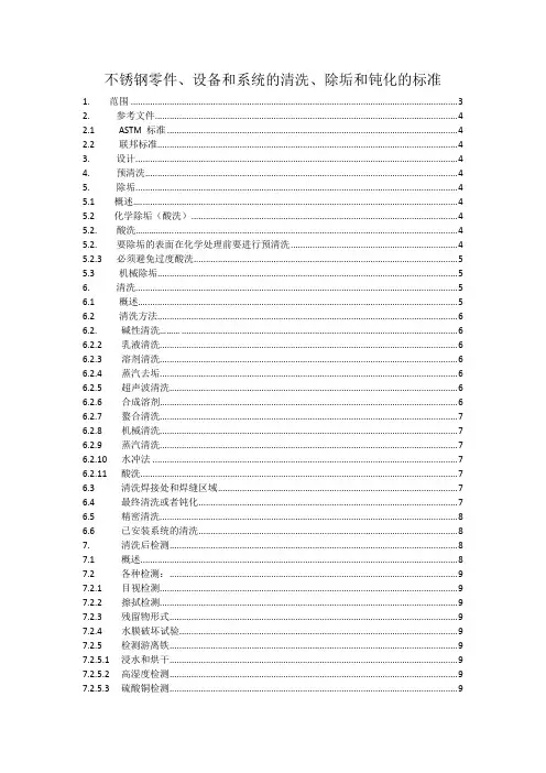
不锈钢零件、设备和系统的清洗、除垢和钝化的标准1. 范围 (3)2. 参考文件 (4)2.1 ASTM 标准 (4)2.2 联邦标准 (4)3. 设计 (4)4. 预清洗 (4)5. 除垢 (4)5.1 概述.... . (4)5.2 化学除垢(酸洗) (4)5.2. 酸洗................. (4)5.2. 要除垢的表面在化学处理前要进行预清洗 (4)5.2.3 必须避免过度酸洗 (5)5.3 机械除垢 (5)6. 清洗 (5)6.1 概述.... .. (5)6.2 清洗方法 (6)6.2. 碱性清洗......... (6)6.2.2 乳液清洗 (6)6.2.3 溶剂清洗 (6)6.2.4 蒸汽去垢 (6)6.2.5 超声波清洗 (6)6.2.6 合成溶剂 (6)6.2.7 螯合清洗 (7)6.2.8 机械清洗 (7)6.2.9 蒸汽清洗 (7)6.2.10 水冲法 (7)6.2.11 酸洗 (7)6.3 清洗焊接处和焊缝区域 (7)6.4 最终清洗或者钝化 (7)6.5 精密清洗 (8)6.6 已安装系统的清洗 (8)7. 清洗后检测 (8)7.1 概述 (8)7.2 各种检测: (9)7.2.1 目视检测 (9)7.2.2 擦拭检测 (9)7.2.3 残留物形式 (9)7.2.4 水膜破坏试验 (9)7.2.5 检测游离铁 (9)7.2.5.1 浸水和烘干 (9)7.2.5.2 高湿度检测 (9)7.2.5.3 硫酸铜检测 (9)7.3 精密检测: (10)7.3.1 溶剂环绕检测 (10)7.3.2 黑光检测 (10)7.3.3 喷雾检测 (10)7.3.4 自由铁的铁锈检测 (10)7.3.4.1 蓝变 (10)8. 预防措施 (11)8.1 将铁感染最小化 (11)8.2 清洗和酸洗溶液的再使用 (11)8.3 冲洗用水 (11)8.4 清洗溶液和冲洗水的流通 (11)8.5 已清洗表面的保护 (12)8.6 安全 (13)8.7 使用过的溶液和水的丢弃 (13)9. 关键词 (13)附录(必要信息) (13)A1 关于不锈钢酸洗除垢的建议和预防措施(见表A1.1) (13)A2 不锈钢酸洗的建议和预防措施(见表格A2.1) (15)1.范围1.1这个标准包括了不锈钢零件、组件、设备和安装系统的清洗、除垢和钝化的所有建议和预防措施。
ASTM D类最新标准目录(十五).docD6473-99(2005) 岩石比重和吸收的腐蚀控制试验方法D6474-99(2006) 高温凝胶渗透色谱检测聚烯烃中分子量分布和分子量平均值的试验方法D6475-00 计算单位面积上防腐覆盖层量的试验方法D6476-05 "充气用织物动态空气渗透性测定的标准试验方法"D6477-04 "轮胎帘线和帘布的相关标准术语"D6478-02 "测定充气用织物密封特性的标准试验方法 "D6479-02 "测定充气用机织织物边角耐精梳性的标准试验方法"D6480-05 用透射电子显微镜对表面擦拭取样中石棉结构值浓度间接制备和分析的标准试验方法D6481-99(2004) 能量分散X射线荧光光谱法检测润滑油中磷、硫、钙、锌的试验方法D6482-01 用搅动抗张法的冷却曲线分析测定液态高聚物骤冷剂冷却特性的试验方法D6483-04 评估T-9柴油机用柴油机油的试验方法D6484/D6484M-04 聚合物基体复合层压材料的开洞耐压强度的测试方法D6485-99(2004) 基体排放的挥发性有机化学药品短期接触的急性和刺激影响的风险描述指南D6486-01(2005) 汽车涂层的短期车辆设备暴露标准实施规范D6487-04 小Joe补偿色浸渍印刷法用胶印墨水预印刷的标准惯例D6488-05 印刷相关问题术语D6489-99(2006) 测定经防水涂层处理过的变硬混凝土吸水性试验方法D6490-99(2006) 用于类水泥面板的无膜成型处理的水蒸气透过的测试方法D6491-99(2003) 在干热试验中预受力的预涂的金属抗老化性的评价标准惯例D6492-99(2003) 检测镀锌和锌/铝合金钢六价铬的标准惯例D6493-05 用自动环和球装置检测烃类树脂的软化点的试验方法D6494-99(2004)e1 测定作为苯可溶性分馏物的工作环境中沥青烟雾颗粒物质的试验方法D6495-02 地面粘土衬认可检验要求指南D6496-04a 测定针刺式土工合成粘土里衬的最上层和底层间平均粘结拉伸强度的试验方法D6497-02 土工薄膜与渗透层或结构间的机械连接指南D6498-99(2002) 对于家庭危险废物操作的家庭危险废物处理培训大纲指南D6499-03 在天然橡胶和它的产品中进行抗原性蛋白质的免疫测量的试验方法D6500-00 用光纤直径分析仪测定羊毛和其它动物纤维直径的试验方法D6501-04 盐水中膦酸酯的测试方法D6502-99(2003) (XRF)用X射线荧光光谱法(XRF)在线测定水中低度微粒和溶解金属的测试方法D6503-99(2005) 用Enterolert测定水中肠球菌试验方法D6504-00 高纯度水中阳离子导电性在线检测规程D6505-00(2006) 检定丙基溴含量试验方法D6506-01 地下防水用沥青防护层规范D6507-00(2005) 复合材料纤维增强定向编码惯例D6508-00(2005)e1 用毛细管电泳法和铬酸盐电解液法测定水基料中可溶无机阴离子的试验方法D6509-00 用玻璃纤维加固不规则聚丙烯改良沥青薄板材规范D6510-00 用于建造屋面系统的沥青的选择指南D6511-00 溶剂负载沥青复合物的试验方法D6512-03 实验室间数值评估惯例D6513-00(2005) 标准耐火测试中计算木结构墙迭加荷载的试验方法D6514-03 透平油高温全氧化测试的试验方法D6515-00(2004) 橡胶轴封从弯曲恢复测定的试验方法D6517-00(2005) 地下水取样的现场保存指南D6518-03a 煤机械取样系统恒定误差试验惯例D6519-05 用液压控固定活塞采样器进行土壤抽样的标准规程D6520-06 挥发性和半挥发性有机化合物分析用水和它的顶部空间的固相微萃取惯例D6521-05 用压力老化容器(PAV)对沥青粘合剂加速老化惯例D6522-00(2005) 测定从往复式发动机,燃气轮机,锅炉,和过程加热器排放物中氧化氮,一氧化碳和氧浓度的试验方法D6523-00(2005) 卫生垃圾掩埋用的可选日常封盖物(ADCs)的评估和选择指南D6524-00(2006) 测量草皮增强垫(TRMs)弹性的试验方法D6525-00(2006) 测量永久性成卷冲刷防护产品公称厚度的试验方法D6526-03e1 毛细管气相色谱法分析甲苯的试验方法D6527-00 用稳态离心法测定多孔介质中不饱和和饱和水分导电率的试验方法D6528-00 粘性土的压密不排水直接样品剪切试验的试验方法D6529-00 馈送50-1000uS/cm的连续电气去电离作用系统的操作性能的试验方法D6530-00(2006) 冷却塔水中活性微生物总量的测试方法(KoolKount化验;KKA)D6531-00(2005) 仪器测量水基墨水的相对着色度的试验方法D6532-00(2006) 关于水凝水泥灰浆样本吸水,清洁防水处理效果评估的试验方法D6534-05 测定机械泵分配器启动力峰值试验方法D6535-05 检定机械泵分配器汲取管长度试验方法D6536-00(2005) 测量机械泵分配器汲取管长度试验方法D6537-00(2006) 包装性能检测用仪表监视包装冲击试验规程D6538-00(2005)e1 自动取样器对废水取样指南D6539-00(2006) 用流动空气测定局部饱水孔隙材料气动渗透性的标准试验方法D6540-05 绒头纱线地板覆盖物的加速染污标准试验方法D6541-05 HFC-236fa、1,1,1,3,3,3-六氟丙烷的标准规范D6542-05 计算堆料中煤吨数的标准规程D6543-00(2006) 用流线煤分析仪进行的测量评价的标准指南D6544-00 紫外线(UV)透射试验前纺织品制备的标准实施规程D6545-00 小孩睡衣裤的织物的可燃性测试方法D6546-00(2005) 工业液压液用弹性密封件能力测定的标准试验方法和建议极限值D6547-00(2005) 双金属电偶用润滑液防腐性能的标准试验方法D6548-00(2005) 薄棉卫生纸抗机械穿透性的标准试验方法D6549-01 搅拌冷却曲线分析法测定冷却剂冷却特性的标准试验方法(Drayton装置)D6550-05 超临界液相色谱法测定汽油中烯烃含量的标准试验方法D6551/D6551M-05 用氙弧曝光器具对压敏胶带做加速老化试验的标准实施规程D6552-06 控制和表征称量聚集的悬浮颗粒的误差的标准规程D6553-00(2005) 导轨润滑剂冷却能力的标准试验方法D6554-00 100%棉粗斜棉布织物的性能规范D6555-03 木制反复使用组件的系统效果评定指南D6556-04 炭黑的标准试验方法.氮吸收法测定总的和外部表面积D6557-04 评估汽车发动机润滑油的防锈性能的试验方法D6558-00a(2005) 碳阳极和阴极块的TGACO2反应率测定标准试验方法D6559-00a(2005) 碳阳极和阴极块的TGA气体反应率测定标准试验方法D6560-00(2005) 原油和石油产品中沥青质(庚烷不溶物)测定的标准试验方法D6561-00 利用(甲氧基-2-苯基-1)哌嗪(MOPIP)测定工作场所空气中气溶胶单体和低聚二异腈酸己二酯(HDI)的标准试验方法D6562-00 利用9-(N-甲氨基甲基)蒽(MAMA)法测定工作场所空气中气态二异腈酸己二酯(HDI)的标准试验方法D6563-05 用毛细管柱气相色谱法分析苯、甲苯、二甲苯及三者浓缩物的试验方法D6564-00(2005) 地表水样现场过滤指南D6565-00(2005) 时间-区域反射计法测定土壤中水(水分)含量的测试方法D6566-00(2006) 测定草皮增强垫的单位面积重量的试验方法D6567-00(2006) 测定草皮增强垫的光线渗透的试验方法D6568-00(2006) 可追溯的化学分析水样的计划编制,执行和报告指南D6569-05 pH1在线测量的标准试验方法D6570-04 机械分级木材指定允许特性的标准实施规程D6571-01 通过静力负载测定高弹性无纺织物的抗压性和复原性的试验方法D6572-00 通过团粒状测试测定粘土的分散性的试验方法D6573/D6573M-01 通用钢丝运输箱规范D6574-00(2006) 用径向流动测定土工织物的(在平面流中)液压透过比的测试方法D6575-00(2006) 测定用做草皮增加垫的土工织物的硬度的试验方法D6576-00 柔性泡沫橡胶化学膨胀规范D6577-00a 工业防护覆层试验的标准指南D6578-00 耐涂写性测定的标准实施规程D6579-00 尺寸筛析色谱法测定烃和萜烯树脂平均分子量和分子量分布的标准实施规程D6580-00(2005) 锌粉涂料与锌粉涂料硫化薄膜和富锌涂层硫化薄膜中金属锌含量测定的标准试验方法D6581-00(2005) 化学悬浮离子色谱法测定饮用水中溴酸盐、亚溴酸盐、氯酸盐和亚氯酸盐的标准试验方法D6582-00(2005) 分等级抽样的标准指南:环境抽样中平均浓度的有效评估D6583-04 涂料薄膜孔隙度的标准试验方法D6584-00e1 气相色谱法测定B-100生物柴油甲酯中自由甘醇和甘醇总值的试验方法D6585-05 未烧结聚四氟乙烯挤压薄膜或胶带规范D6586-03 用快速小刻度柱测试法预测水系中粒状活性炭污染物吸附惯例D6587-00 用自动试验机测试纱线支数的试验方法D6588-02 轮胎帘布的疲劳试验方法(圆盘疲劳试验)D6589-05 大气散射模型性能统计评估指南D6590/D6590M-00(2006) 密封纤维容器和罐用压敏胶带规范D6591-00 高效液相色谱法折射率检测中间馏分中芳烃类型的试验方法D6592-01 轻便式化学发光水质测定的标准试验方法D6593-06 低温和轻型条件下运行的、以汽油为燃料的火花点火式内燃发动机内对抑制沉积物形成的汽车机油评价的标准试验方法D6594-05 135℃时柴油机油腐蚀性评价试验方法D6595-00(2005) 用转盘式电极原子发射光谱法测定用过的润滑油或用过的液压水流体中磨耗金属和污染物的试验方法D6596-00(2005) 汽油和相关烃类材料的安瓿瓶封装和贮藏惯例D6597-00(2006) 评估场所封闭达到净化等级惯例D6598-00 监测垂直变形用沉降平台的安装和操作指南D6599-00 斜坡上活柴笼建造惯例D6600-00(2004) 评估橡胶检验方法的测试灵敏度惯例D6601-02 用无转子剪切流变仪测量硫化和硫化后橡胶动态性能的试验方法D6602-03b 炭黑易消散物或/和其它环境微粒的取样和测试惯例D6603-00 防紫外线纺织品标签指南D6604-00 示差扫描量热法测定烃类树脂玻璃透过温度惯例D6605-00 测定加热后烃类树脂的颜色稳定性的试验方法D6606-00(2005) 通过Duke粘度计测定漆料和清漆的粘度和屈服的试验方法D6607-00(2005) 在规格界限中精密度声明变化的内容惯例D6608-00(2006) 在沥青混合物中鉴定特立尼达湖沥青惯例D6609-01 煤随机抽样的标准指南D6611-00 湿和干的条件下纱与纱之间抗磨损性的测试方法D6612-00 用自动检测器测定纱数和纱数可变性的试验方法D6613-02 尼龙或聚脂纤维尺寸确定的标准实施规程D6614-00 恒延伸法测定纺织纤维的伸展性能的试验方法D6615-06 喷口B广馏份航空涡轮机燃料标准规范D6616-01a(2006) 在摄氏100度时用锥形承载模拟器粘度计测量高剪切速率时粘度的标准试验方法D6617-05 用来自标准材料的单个试验结果的试验室偏差测定惯例D6618-05 在四冲程循环超动力柴油机1M-PC单气缸油检验发动机中的发动机油评估测试方法D6619-00(2006) 通过高速分散合并颜料惯例D6620-00 基于计数测定石棉探测范围惯例D6621-00(2006) 芳烃材料用生产分析器的性能试验惯例D6622-01 完全粘结的热铺增强防水系统应用的指南D6624-06 利用河流分析仪数据测定收集的分批处理流动物质的流量比例平均特性值(FPAPV)的标准实施规程D6625-01 用荧光紫外-集中光-水-冷凝曝光和曝水仪器对涂漆板抛光防护性能试验的标准实施规程D6626-01 分级特立尼达湖地改良沥青粘合剂规范D6627-01 冷沥青混合料挥发性馏份测定试验方法D6628-03 路面标记材料颜色规范D6629-01 由于腐蚀引起的土壤损耗的评价方法的选择指南D6630-01 低坡度绝热屋顶薄膜装配性能指南D6631-05 进行实验室间研究和测定试验方法精确度的委员会D01标准指南D6632-01 防污油漆中铜总量试验方法D6633-05 机械泵分配器的基本功能稳定性的标准试验方法D6634-01(2006) 地下水监测井用净化和取样选择的标准指南D6635-01 平板膨胀剂表现测试方法D6636-01(2006) 加筋土工薄膜的剥纸强度的测定的标准试验方法D6637-01 单边或多边拉伸法测定土工格栅拉伸特性的标准试验方法D6638-01 土工合成加筋和分段式混凝土构件间的连接强度的测定的标准试验方法(模数化混凝土块)D6639-01 地下勘察用频域电磁法使用指南D6640-01(2005) 环境勘察用岩心管样品机获取的土壤的收集和处置的标准实施规程D6641/D6641M-01e1 用组合式荷载压力试验夹具测定聚合物基质复合叠材的压力特性的标准试验方法D6642-01(2006) 确定土壤水(湿度)流量的方法比对指南D6643-01 木基板材角部抗冲击性测试试验方法D6644-01(2002) 有眼镶边纽扣抗拉强度试验方法D6645-01 红外分光光度测定法测定聚乙烯中甲基(共聚单体)含量试验方法D6646-03 测定粒状和丸状活性炭的加速硫化氢突破容量试验方法D6647-01 通过原子吸收测定酸性可溶铁试验方法D6648-01 沥青蠕变强度测定试验方法D6650-01 测定净室中使用无纺织物动擦除效率、湿颗粒去除能力和织物粒子作用试验方法D6651-01 无纺织物吸附率和吸附能力测定试验方法D6652-01 测定无纺织物留下的纤维状碎屑试验方法D6653-01 真空法测定高空对包装系统影响试验方法D6654-05 机械泵分配器基本储存稳定性试验方法D6655-01 机械泵分配器相关术语D6656-01 测定湿铬鞣革中氧化铬试验方法(高氯酸氧化)D6657-01 测定湿铬鞣革pH值试验方法D6658-01 通过烘炉干燥测定湿铬鞣革的挥发性物质(湿度)试验方法D6659-01 物理和化学试验用湿铬鞣革的取样和制备规程D6660-01 自动相变法测定含水乙二醇基发动机冷却剂凝固点试验方法D6661-01(2006) 用擦拭取样方法从表面现场收集有机化合物规程D6662-01 聚烯烃基塑料甲板规范D6663-01 公共场所用和家用编织和针织床罩及附属品规范D6664-01 公共场所用和家用编织、针织和棉绒的床上品规范D6665-01 在沸水试验中评价预应力预涂金属耐老化的标准实施规程D6666-04 评价含水高聚物淬火剂的标准指南D6667-04 紫外线荧光法检测气态烃和液化石油气中挥发性硫总量试验方法D6668-01 F=0和F=1的易燃性额定值间的区分的标准试验方法D6669-01a 醇酸和乳胶内部涂料暴露评定用暴露方案的选择和设计的标准实施规范D6670-01 室内材料/产品排放的挥发性有机物质的全室测定的标准实施规程D6671/D6671M-06 非方向性纤维增强多聚矩阵元件的混合模式I-模式II内层裂纹强度的标准试验方法D6672-06 格式化驱动数值控制的切布机的切割数据的标准实施规程D6673-04 缝制品图案数据交换数据格式的标准实施规程D6674-01 织物用熟练试验程序的标准指南D6675-01 机动车薄钢板上有机涂层的盐加速户外表面腐蚀试验的标准实施规程D6676-01e1 用内部加热测定高温下外部管道镀层的阴极断接的标准试验方法D6677-01 用刀评价粘结性的标准试验方法D6681-05 高速单缸柴油机履带车1P测试程序中发动机油的评估试验方法D6682-01 使用Peschl旋转分开水平撕裂试验机测量粉末撕裂应力的试验方法D6683-01 粉末和其它散料的容积密度的试验方法D6684-04 咬合混凝土块铺面系统的原料和制造规范D6685-01 纤维制混凝土用织物的试验方法的选择的标准指南D6686-01 覆层抗丹宁着色评定的标准试验方法D6687-04 印刷油墨载体和成分测试的标准导则D6688-01 夹层法测定印刷品耐液态化学品腐蚀性试验方法D6689-01 同样试验组织内多层工作台最优控制和报告试验方法不确定性的标准指南D6690-06 沥青铺路和混凝土热应用连接和裂纹密封剂标准规范D6691-01 利用规定的微生物团测定塑料材料在海洋环境中需氧生物降解能力的标准试验方法D6692-01 海水中放射性同位素标记的聚脂塑料的生物降解性的测定的标准试验方法D6693-04 非增强聚乙烯和非增强柔性聚丙烯土工薄膜张力特性的测定的标准试验方法D6694-01 喷射聚氨基甲酸乙酯泡沫屋面结构使用的液硅涂层的标准规范D6695-03b 清漆和相关涂覆料的氙弧曝光操作规程D6696-05e1 了解氰化物种类指南D6697-01 化学需氧量(锰III需氧量)测定试验方法D6698-01 水中5NTU以下混浊度的联机测量的标准试验方法D6699-01(2006) 用水斗取液体样的标准惯例D6700-01(2006) 轮胎废料产生的燃料的使用惯例D6701-01 测定水蒸气通过无纺织物和塑料衬层的透过速率试验方法D6702-01 检定非清洁用的无纺布的动态擦除效果试验方法D6703-01 自动Heithaus滴定试验方法D6704-01 检定冷混合沥青修补材料可成形性试验方法D6705-04 喷射成形聚氨酯泡沫体屋顶系统的维修和重新涂覆指南D6706-01 测定土壤中土工织物抗拉出的测试方法D6707-06 地下排水设施用圆形织法的土工织物规范D6708-06 两种测量材料同一性能的试验方法之间预期一致性的统计分析和改进惯例D6709-06 序列VIII火花点火发动机(CLR油试验发动机)中汽车发动机油评定试验方法D6710-02 烃基淬火油评价指南D6711-01 用于填充金属筐,水泥沉床,和金属筐沉床的石块分类惯例D6712-01 超高分子量聚乙烯(UHMW-PE)实心塑料型材规范D6713-01 (PVDF)由聚偏氟乙烯制成的挤制和压模制型材规范D6714-01 灰化湿铬鞣革中氧化铬的试验方法(高氯酸氧化)D6715-01 用盐保存(腌干)兽皮的理化检测取样和准备惯例D6716-01 湿铬鞣革中总灰份的标准试验方法D6717-01 弹性纱线(绞纱样品)线密度试验方法D6718-02 D13委员会标准的编写规程D6719-05。

ASTM D类最新标准目录( 一)D4-86(2004) 沥青含量试验方法D5-06e1 沥青材料的渗透性试验方法D6-95(2000)e1 油及沥青混合物加热损失试验方法D8-02 与道路和路面材料相关的术语D9-05 与木材相关的术语D12-88(1998) 未加工的桐油D13-02 松节油规范D16-03 与涂料、清漆、亮漆和有关产品相关的术语D20-03 路面焦油的蒸馏试验方法D25-99(2005) 圆木桩D29-98 虫胶树脂的抽样和试验方法D34-91(2003) 白颜料化学分析指南D36-95(2000)e1 沥青软化点试验方法(沥青软化点测定器)D38-94(2000)e1 木材防腐剂的抽样试验方法D41-05 铺屋面、防潮及防水用沥青底层D43-00 屋顶、防潮及防水材料用杂酚油底漆D49-83(2002) 铅丹的化学分析D50-90(2005) 含铁和锰的黄色、橙色、红色和褐色涂料的化学分析试验方法D56-05 泰格密闭闪点试验器测定闪点的试验方法D61-75(2004) 硬沥青的软化点的试验方法(水中方块试验法)D69-01 磨擦带的试验方法D70-03 半固态沥青材料的比重和密度的试验方法D71-94(2004) 固体硬沥青和地沥青的相对密度试验方法(变位法)D75-03 集料的抽样D76-99(2005) 纺织材料的抗拉试验机D79-86(2004) 氧化锌颜料D81-87(2003) 碱性碳酸盐铅白颜料D83-84(2002) 铅丹颜料D85-05 赭色颜料规范D86-05 大气压下石油产品蒸馏试验方法D87-04 石蜡熔点的试验方法(冷却曲线)D88-94(2005) 赛波特粘度的试验方法D91-02 润滑油的沉淀值试验方法D92-05a 用克利夫兰德开杯法测定石油产品的闪点和燃点的试验方法D93-02a 用潘斯基-马丁斯仪闭杯闪点测定器测定闪点的试验方法D94-02 石油产品的皂化值试验方法D95-05e1 蒸馏法测定石油产品及沥青材料中水的试验方法D97-05a 石油的倾点的试验方法D98-05 氯化钙D113-99 沥青材料的延展性的试验方法D115-02 电绝缘用含清漆试验溶剂的试验方法D116-86(2006) 电气设备用上釉陶瓷材料的试验D117-02 产自石油的电绝缘油的试验方法和规范导则D120-02a 橡胶绝缘手套D121-05 煤和焦炭术语D123-03 与纺织材料相关的术语D124-88(1998) 脱胶的豆油D126-87(2002) 含铬酸铅和氧化铬绿的黄、橙和绿色颜料的化学分析方法D127-05 石油蜡包括凡士林滴熔点的试验方法D128-98(2003)e1 润滑脂分析试验方法D129-00(2005) 石油产品中硫含量试验方法(通用氧弹法)D130-04e1 用铜条变色法检测石油产品对铜腐蚀性的测试方法D139-95(2001)e1 沥青材料浮选试验的检测方法D140-01 沥青材料的抽样D143-94(2000)e1 洁净木材小样品的试验D146-04 防水与屋面材料用沥青浸渍的油毡和编织物的抽样与试验方法D149-97a(2004) 固体电绝缘材料在工业电源频率下的介电击穿电压和介电强度的试验方法D150-98(2004) 固体电绝缘材料的(恒久电介质)的交流损耗特性和介电常数的测试方法D153-84(2003) 颜料比重测试方法D154-85(2001) 清漆试验D156-02e1 石油产品赛波特比测试方法(赛波特比色计法)D167-93(2004)e1 块焦比重和孔隙度的试验方法D168-94(2000) 杂酚油焦炭渣的测试方法D173-03 屋顶和防水材料用饱和沥青棉织物D176-00 电绝缘用固体充填化合物与浸渍剂的试验方法D178-01(2005) 橡胶绝缘垫子D185-84(1999 颜料,糊剂及涂料中粗颗粒的试验方法D187-94(2003)e1 煤油燃烧质量的测试方法D189-05 石油产品康拉孙残碳测试方法D197-87(2002) 粉煤的取样方法与细度试验方法D198-05a 结构尺寸木料静力试验法D202-97(2002)e1 电绝缘用未浸渍纸的抽样和试验方法D204-02 缝线的测试方法D209-81(2003) 灯黑颜料D210-05 骨炭颜料D211-67(2002) 铬黄和铬橙颜料D215-91(2002) 白色亚麻籽油涂料的化学分析D217-02 润滑剂针入度的测试方法D225-04 表面有矿物颗粒的沥青屋面板D226-06 铺顶和防水用沥青饱和有机毡D227-03 铺顶和防水用焦油沥青饱和有机毡D228-06 沥青屋面卷材,盖板和瓦的试验方法D229-01 电绝缘用硬质薄板及板材的试验方法D233-02 松脂的抽样和测试试验方法D234-82(1998) 生亚麻子油D235-02 矿物溶剂油(石油溶液油)(烃干洗溶液)规格D237-57(1997) 橙色紫胶和其他虫胶D240-02 弹式量热器测定液烃燃料燃烧热的试验方法D242-04 沥青铺路混合料用矿物填料D243-02 规定残渣渗透性测试方法D244-04 乳化沥青的测试方法D245-06 制定目测分等木材的结构等级及有关允许性能的规程D246-04 杂酚油和杂酚油-煤焦油溶液的蒸馏试验方法D256-06 塑料及电绝缘材料的抗冲击性的测试方法D257-99(2005) 绝缘材料的直流电阻或电导的试验方法D260-86(2001) 熟亚麻籽油D261-75(1999) 铁蓝颜料D262-81(1999) 群青蓝颜料D263-05 氧化铬绿颜料D267-82(2003) 黄青铜粉规格D268-01 涂料及其相关涂层和原料用挥发性溶剂及化学中间体的抽样和测试D269-97(2002) 松香和松香衍生物中不溶物的试验方法D276-00a 纺织品中纤维的鉴定方法(AATCC方法20)D279-02 颜料渗出的试验方法D280-01 颜料吸收的水份(及试验条件下挥发的其他物质)的测试方法D281-95(2002) 用刮刀磨损法测定颜料油吸附性的试验方法D283-84(1999) 一氧化铜和铜涂料化学分析试验方法D287-92(2006) 原油和石油产品API比重的试验方法(液体比重计法)D291-86(2002) 烟煤立方英尺重量的试验方法D293-93(2004) 焦炭筛析分析试验方法D295-99(2004) 电绝缘用棉质漆布的试验方法D297-93(2002)e2 橡胶制品的测试方法.化学方法D299-04e1 石棉纱的标准规范D301-95(2004) 可溶性硝化纤维素的试验方法D304-05 n-丁醇(丁醇)D305-84(2003) 黑色涂料中的溶剂萃取材料的试验方法D312-00 屋顶用沥青D315-95(2004)e1 机织石棉带的标准规范D319-04 合成的戊醇D322-97(2002)e1 蒸馏法测定汽油发动机废机油中汽油稀释剂的试验方法D323-99a 石油产品蒸气压力的测试方法D329-02 丙酮D330-93(2001) 2-丁氧基乙醇D331-05 2-乙氧基乙醇D332-87(2004) 白色颜料着色力的试验方法D333-01 透明漆和着色漆的试验方法D341-03 液体石油产品粘度-温度关系曲线图D344-97(2004) 用擦试外规评定法对涂料相对遮盖力的测试方法D345-02 道路和结构用氯化钙的抽样和试验方法D346-04e1 实验室分析用焦炭试样的收集和制备D347-97 杂酚油和煤焦油的体积和比重修正表D348-00 电绝缘用刚性管的测试方法D349-99(2004) 电绝缘用层压圆棒的试验方法D350-01 电绝缘用经处理软套管的试验方法D351-97(2003) 天然白云母块及薄片目检质量分级D352-97(2003) 电绝缘用涂浆云母的试验方法D358-98 涂料耐大气老试验用木片规格D360-89(2001) 紫胶清漆规范D363-90(2000) 磷酸三甲苯酯规格D365-01(2005) 可溶性硝酸纤维素基溶液的试验方法D367-94(2000)e1 杂酚油中苯不溶物的测试方法D368-89(2002) 杂酚油及油质防腐剂比重的试验方法D369-84(2002) 杂酚油馏份与残渣比重的测试方法D370-02e1 油质防腐剂脱水作用的试验方法D372-00(2006) 电绝缘用经处理的软套管规格D374-99(2004) 固体电绝缘厚度的测试方法D374M-99(2005) 固体电绝缘厚度的标准测试方法(米制)D375-95(2004)e1 石棉粗砂的标准规范D378-00 平型橡胶传送带的测试方法D380-94(2006) 橡胶软管的测试方法D381-04 用喷射蒸发法测定燃烧中原在胶的测试方法D387-00 使用机械研磨机测定有色颜料主色和着力色的试验方法D388-05 用排列法测定煤的分类D390-92(1999) 海上,陆地及淡水中用木桩,电杆和木材的防腐处理用煤柏油杂酚油规程D391-94(2000)e1 杂酚油-煤焦油溶液D395-03 橡胶压缩永久变形特性的试验方法D396-05 燃料油规范D402-02 稀释沥青产品蒸馏的测试方法 Standard Test Method for Distillationof Cut-Back Asphalt ic (Bituminous) ProductsD409-02 粉碎机法测定煤炭可磨性的试验方法 Standard Test Method for Grindabilityof Coal by t he Hardgrove-Machine MethodD411-98(2003) 电绝缘用紫胶片试验方法 Standard Test Methods for ShellacUsed for Electrical I nsulationD412-98a(2002)e1 硫化橡胶、热塑橡胶和热塑合成橡胶的拉伸试验方法 Standard Test Methods f or VulcanizedRubber and Thermoplastic Elastomers—TensionD413-98(2002)e1 橡胶特性-与软质基底粘附性的试验方法 Standard Test Methods for RubberPro perty—Adhesion to Flexible SubstrateD420-98(2003) 土壤粒度分析的测试方法 Standard Guide to SiteCharacterization for Engineering, Design, and ConstructionPurposesD421-85(2002) 土壤粒度分析试验方法 Standard Practice for Dry Preparationof Soil Samples for Particle-Size Analysis and Determination ofSoil ConstantsD422-63(2002)e1 土壤粒度分析试验方法 Standard Test Method forParticle-Size Analysis of Soils D425-88(2001) 土壤离心湿度当量试验方法 Standard Test Method for CentrifugeMoisture Equiva lent of SoilsD427-04 用水银法测量土壤收缩系数的测试方法 Test Method for Shrinkage Factors ofSoils by t he Mercury MethodD429-03e1 橡胶特性与硬质基底粘附性的试验方法 Standard Test Methods for RubberProperty—Adhesion to Rigid SubstratesD430-06 橡胶变质的动态疲劳试验方法 Standard Test Methods for RubberDeterioration-Dynamic FatigueD434-95 Standard Test Method for Resistance toSlippage of Yarns in Woven Fabrics Using a St andard SeamD440-86(2002) 煤的跌落粉碎试验 Standard Test Method of Drop ShatterTest for CoalD441-86(2002) 煤的滚筒试验 Standard Test Method of Tumbler Test for CoalD444-88(2003) 锌黄颜料(铬酸锌黄)的化学分析方法 Standard Test Methods for Chemical Analysis of Zinc YellowPigment (Zinc Chromate Yellow)D445-06 透明和不透明液体运动粘度的测试方法.(包括动态粘度的计算) Standard Test Method for Kinematic Viscosity ofTransparent and Opaque Liquids (and the Calculation of DynamicViscosity)D446-06 玻璃毛细管运动粘度计操作说明书和规范 Standard Specifications and OperatingInstructi ons for Glass Capillary Kinematic ViscometersD448-03a 道路和桥梁建筑的集料尺寸分类 Standard Classification for Sizes ofAggregate for Roa d and Bridge ConstructionD449-03 防潮和防水用沥青规范 Standard Specification for AsphaltUsed in Dampproofing and WaterproofingD450-96(2006) 铺屋面,防潮与防水用硬煤沥青 Standard Specification for Coal-TarPitch Used in Roofing, Dampproofing, and WaterproofingD451-91(2002) 沥青屋顶制品用粒状矿物铺面材料筛分分析试验方法 Standard Test Method for Si eveAnalysis of Granular Mineral Surfacing For Asphalt RoofingProductsD452-91(2002) 沥青层面制品表面修整用非粒状矿物的筛分试验方法 Standard Test Method for Si eveAnalysis of Surfacing for Asphalt Roofing ProductsD453-94(2000)e1 杂酚油-煤焦油溶液中焦油酸含量的测试方法 Standard Test Method for Tar Aci ds inCreosote-Coal Tar SolutionsD454-04 用加热及空气压力测定橡胶变质的试验方法 Standard Test Method for RubberDeteriorat ion by Heat and Air PressureD459-00 肥皂和其它洗涤剂的术语规范 Standard Terminology Relating toSoaps and Other Deter gentsD460-91(2005) 肥皂和其它洗涤剂粒度的试验方法 Standard Test Methods for Samplingand Che mical Analysis of Soaps and Soap ProductsD464-05 松脂油产品包括妥尔油和其他相关产品的皂化值的试验方法 Standard Test Methods for Saponification Number of Naval Store Products Including Tall Oil and Other Related ProductsD465-05 松脂制品包括妥尔油及其它相关产品酸值的试验方法 Standard Test Methods for Acid N umberof Naval Stores Products Including Tall Oil and Other RelatedProductsD470-05 电线和电缆用交联绝缘与套管的测试方法 Standard Test Methods for CrosslinkedInsulati ons and Jackets for Wire and CableD471-98e2 液体对橡胶性能影响的测试方法 Standard Test Method for RubberProperty-Effect of LiquidsD473-02 萃取法测定原油和燃料油中沉积物的试验方法 Standard Test Method for Sediment inCr ude Oils and Fuel Oils by the Extraction MethodD476-00(2005) 二氧化钛颜料规范 Standard Classification for DryPigmentary Titanium Dioxide P roductsD478-02 锌黄(铬酸锌)颜料 Standard Specificationfor Zinc Yellow (Zinc Chromate) PigmentsD480-88(2003) 铝粉和铝粉浆的抽样和试验方法 Standard Test Methods for Samplingand Testin g of Flaked Aluminum Powders and PastesD482-03 石油产品灰分的测试方法 Standard Test Method for Ash fromPetroleum ProductsD483-04 石油制植物喷洒油不磺化残渣的试验方法 Standard Test Method for UnsulfonatedResidu e of Petroleum Plant Spray OilsD490-92(2005) 道路柏油 Standard Specification for Road TarD494-04 Standard Test Method for Acetone Extraction ofPhenolic Molded or Laminated Products Standard TestMethod for Acetone Extraction of Phenolic Molded or LaminatedProductsD495-99(2004) 固体电绝缘材料的耐高压低电流干电弧性能的测试方法 Standard Test Method for High-Voltage, Low-Current, Dry Arc Resistance of Solid ElectricalInsulationD500-95(2003) 磺化油和硫化油的化学分析和试验方法D501-03 碱性洗涤剂的抽样和化学分析试验方法D502-89(2003) 肥皂和其它洗涤剂粒度的试验方法D509-05 松香分级和抽样试验方法D511-03 水中钙镁离子的测试方法D512-04 测定水中氯离子含量的试验方法D513-02 水中二氧化碳溶解量和总量的试验方法D516-02 水中硫酸铁的试验方法D517-98(2003) 沥青厚板材D518-99 橡胶变质表面龟裂的试验方法D519-04 羊毛条中纤维长度的试验方法D520-00(2005) 锌粉颜料规范D521-02 锌粉(金属锌粉)的化学分析试验方法D522-93a(2001) 用锥形心轴仪测定涂覆有机涂层延伸率的试验方法D523-89(1999) 镜面光泽的试验方法D524-04 石油产品中兰氏残炭的试验方向D525-05 汽油氧化稳定性的试验方法(诱导期方法)D528-97(2002) 纸和纸板的机器定向试验方向D529-04 沥青材料的加速风化试验条件和程序的测试方法(碳弧法)D531-00(2005) 普西和琼斯橡胶压缩试验方法D542-00 透明有机塑料的折射指数的试验方法D543-06 塑料耐化学试剂性能的试验方法D545-99(2005) 混凝土用预制伸缩缝纫填料的试验方法(非挤压和弹性型)D546-05 道路和铺砌材料用矿物填料筛分的测试方法D548-97(2002) 纸张水溶解酸碱度的试验方法D555-84(1998) 干性油试验D558-04 土壤水泥混合物的水分与密度关系的试验方法D559-03 压实的掺土水泥混合物的湿润与干燥的试验方法D560-03 压实的掺土水泥混合物的冻融试验方法D561-82(2003) 涂料用炭黑颜料D562-01(2005) 斯氏粘度计测定涂料稠度的试验方法D563-88(1996)e1 醇酸树脂和树脂溶液中苯酐含量的试验方法D564-87(2002) 液体涂料催干剂的试验方法D565-99(2005) 白色矿物油中可碳化物质的试验方法D566-02 润滑脂滴点的试验方法D570-98(2005) 塑料吸水率的试验方法D572-04 用加热法和氧化法进行的橡胶变质的试验方法D573-04 在空气烤炉中作橡胶变质的试验方法D575-91(2001) 橡胶压缩特性的试验方法D578-05 玻璃纤维丝D579-04 原织物玻璃纤维D580-04 机织玻璃纤维带D581-99 机织玻璃纤维套管的编织D584-96(2005) 原毛中羊毛含量实验室测试方法D585-97(2002) 纸张、纸板、纤维板和相关产品的单批取样和验收方法D586-97(2002) 纸中灰分含量的试验方法D589-97(2002) 纸的不透明度的测试方法D590-93(2002) 纸中石油蜡的测试方法D596-01 水分析结果的报告D600-90(2001) 液体涂料催干剂D601-87(1998) 奥气油(永久液体)D602-81(2003) 硫酸钡颜料规范D605-82(2003) 硅酸镁颜料(滑石)D607-82(2003) 湿磨云母颜料D608-05 邻苯二甲酸二丁酯D609-00 涂料、油漆以及改性涂料与相关涂料产品的测试用冷轧钢板的制备D610-01 涂漆钢表面锈蚀程度评价的试验方法D611-04 石油产品和烃类溶剂苯胺点和混合苯胺点的试验方法D612-88(2004) 石蜡中可碳化物质的试验方法D613-05 十六烷法测定柴油燃料燃烧质量的试验方法D618-05 塑料及电绝缘材料的调理方法D619-99(2004) 电绝缘用硫化纤维的测试方法D622-99(2005) 汽车空气制动和真空制动系统用橡胶软管试验方法D623-99e1 橡胶特性-压缩中热的产生及挠曲疲劳的试验方法D624-00e1 橡胶的热塑性弹性的耐老化性的抗撕裂强度的试验方法D628-95(2004)e1 石棉套管的标准规范D629-99 纺织品定量分析试验方法D632-01 氯化钠D633-97(2005) 道路柏油的体积修正表D635-06 自承塑料在水平状态时的燃烧速率或者燃烧蔓延程度及燃烧时间的试验方法D638-03 塑料拉伸性能的试验方法D642-00(2005) 船用集装箱、组合件和单体加载的抗压缩能力的测试方法D643-97(2002) 用厦泊测试仪测试纸的折痕持久性的标准试验方法D644-99(2002) 用烘干法测定纸和纸板中水分的测试方法D645/D645M-97(2002) 纸和纸板厚度的测试方法D646-96(2001) 纸张及纸板的基本重量的试验方法(单位面积的重量)D648-06 在挠曲负荷下塑料的挠曲温度的试验方法D653-05 土壤、岩石和其内部所含液体的相关术语D660-93(2005) 外用漆龟裂程度评价方法D661-93(2005) 外用漆破裂程度评价的试验方法D662-93(2005) 外用漆侵蚀程度评价的试验方法D664-06 电位滴定法测定石油产品酸值的试验方法D665-06 水存在下抑制的矿物油防锈特性的试验方法D668-99(2004) 电绝缘用硬条和硬管尺度测量的测试方法D669-03 层压薄板与层压板的平行于层片的耗散系数和介电常数的试验方法D685-93(2002) 检测调理纸和纸制品D686-93(2002) 纸中矿物填料和矿物涂料的定性测试方法D689-03 纸张的内部耐撕裂的试验方法D692-00(2004) 沥青铺路砌混合用粗集料D693-03a 碎石路面用压碎集料D695-02a 硬质塑料抗压特性的试验方法D696-03 从-30摄氏度到30摄氏度的塑料线性热膨胀系数的试验方法D698-00ae1 实验室中用12000ft-lbt/ft(600KN-m/m)作用力测定土壤压力特性的试验方法D704-99(2004) 三氯氰胺甲醛模制化合物D705-99(2004) 脲甲醛模制化合物D706-05 乙酸纤维素模制和挤压化合物D707-05 醋酸丁酸纤维素模制与挤压料规格D709-01 层压热固材料D710-97(2002) 电绝缘用硫化纤维薄板、条和管D711-89(2004) 路标漆不粘着时间的试验方法D713-90(2004) 路标漆进行路面使用的试验方法D714-02e1 涂料起泡程度的试验方法D715-86(2003) 硫酸钡颜料分析的标准试验方法D716-86(2003) 评定云母颜料的标准试验方法D717-86(2003) 硅酸镁颜料分析的标准试验方法D718-86(2003) 硅酸铝颜料的分析标准试验方法D720-91(2004)e1 煤自由膨胀指数的试验方法D721-05 石油蜡含油量的试验方法D722-93(2002) 纸的抗油脂性标准试验方法D724-99(2003) 纸表面可湿性的测试方法(接触角法)D726-94(2003) 空气中无孔纸的透气性的测试方法D727-96(2001) 真空方法测定屋顶和地板油毡煤油值的试验方法D731-95(1999) 热固模塑料粉末的模塑指数的试验方法D732-02 用穿孔工具测量塑料剪切强度的测试方法D737-04 纺织纤维透气率的试验方法D740-05 丁酮规范D746-04 用冲击法测定塑料及弹性材料的脆化温度的试验方法D747-02 用悬臂梁法对塑料表观弯曲系数的测试方法D748-00(2005)e1 固定式云母介电电容器用天然云母块和云母薄片D750-00 用碳弧型装置和风化装置对橡胶变质的测试方法D751-06 涂层织物的测试方法D763-01 未加工棕土和焙烧棕土颜料D765-87(2003) 未加工黄土和焙烧黄土颜料技术规范D768-01 黄色氧化铁的水合物D769-01 黑色合成氧化铁D770-05 异丙醇规范D772-86(2005) 外部涂料剂落程度评价的试验方法D774/D774M-97(2002) 纸张抗破碎强度的测试方法D776-92(2001) 干热对纸和纸板特性的影响的试验方法D777-97(2002) 经过处理的纸和纸板易燃性的标准试验方法D778-97(2002) 纸萃液(热萃取和冷萃取法)氢离子浓度(pH)的标准试验方法D779-03 纸、纸板和其他印刷材料用干烧指示器法测试耐水性的测试方法D780-95(2003) 纸印刷油墨渗透性的测试方法(蓖麻油试验)D784-03 电绝缘材料用橙色紫胶和其他印度虫胶D785-03 塑料和电绝缘材料的洛氏硬度的测试方法D787-96(2003) 乙基纤维模制和挤压化合物D788-05 甲基丙烯酸酯模制和挤压化合物的分类系统D789-06 聚酰胺相对粘度,熔点和含水量的测试方法D790-03 未增强和增强塑料及电绝缘材料的挠曲性的试验方法D792-00 用位移法测定塑料密度和比重(相对密度)的标准试验方法D800-05 工业用金属除垢剂化学分析试验方法D801-02 二聚戊烯抽样和测试的试验方法D802-02 松油抽样和测试的试验方法D803-03 妥儿油的测试试验方法D804-02 松脂制品包括妥儿油及相关产品的术语D806-00(2006) 掺土水泥混合物中水泥含量的试验方法D807-05 工业锅炉用水引起脆裂倾向的评价方法(美国矿业局的脆变检查器方法)D808-05 新的和使用过的石油产品中氯含量的试验方法(氧弹法)D813-06 测定橡胶龟裂扩展的试验方法D814-95(2005) 橡胶特性挥发性液体蒸汽渗透性的试验方法D816-06 橡胶胶水的试验方法D817-96(2004) 乙酸丙酸纤维素和醋酸丁酸纤维素的试验方法D820-93(2003) 含合成洗涤剂肥皂的化学分析试验方法D822-01 用经过过滤明光碳弧灯和水中曝光装置对涂料及相关涂层和材料上做的导电试验D823-95(2001) 色漆,清漆,喷漆及有关产品制成厚度均匀漆膜试片的方法D824-94(2002) 用皱文纸测定吸水率的测试方法D828-97(2002) 纸和纸板拉力破坏强度的测试方法D829-97(2002) 纸和纸制品湿抗拉断裂强度的标准试验方法D831-94(2004) 电缆及电容器油的气体含量的测试方法D832-92(2001)e1 低温状态下的橡胶试验D841-02 甲苯的硝化定级D843-06 硝化二甲苯D847-04 苯,甲苯,二甲苯,溶剂石脑油和类似的工业芳烃酸度的试验方法D848-03 工业芳烃的酸洗颜色的标准试验方法D849-05 工业芳烃对铜条腐蚀的标准试验方法D850-03 工业芳轻及相关物质的蒸溜法D852-02 苯凝固点的试验方法D853-04 工业芳烃中硫化氢和二氧化硫含量(定性)的标准试验方法D854-06 土壤比重的试验方法D857-02 水中铝含量的测试方法D858-02 水中锰含量的试验方法D859-05 水中二氧化硅的测试方法D861-01a 用特克斯制命名纤维,纱的半制品,纱和其它纺织品线度D865-99(2005) 橡胶的空气中加热变质试验方法(试管法)D866-99(2004) 电线及电缆用丁苯合成橡胶套D868-85(2003) 路标漆渗色程度评价的试验方法D869-85(2004) 涂漆沉降程度评价试验方法D870-02 水浸渍法涂层耐水试验D871-96(2004) 测试乙酸纤维素的试验方法D873-02 航空燃料的氧化稳定性的测试方法D874-06 润滑油和添加剂中硫酸盐类灰分的测试方法D876-00 电绝缘用刚性氧化乙烯聚合物管的测试方法D877-02e1 用圆盘电极测定电绝缘液体介电击穿电压的试验方法D878-01e1 绝缘油中无机氯化物和硫酸盐的测试方法D880-92(2002) 船用集装箱的冲击试验的试验方法D882-02 塑料薄板材抗拉特性的试验方法D883-00 塑料相关术语D885-06 由人造有机纤维制成的轮胎帘子线,轮胎帘布和工业长纱线的测试D887-82(2003)e1 水沉积物抽样D888-05 水中溶解氧的试验方法D889-99(2004) 松香中油挥发性的试验方法D890-98(2003) 液体松脂中水含量的试验方法D891-95(2004) 液态工业化合物的比重,表观比重的测试方法D892-05 润滑油发泡特性的标准试验方法D893-05a 用过的润滑油中不溶物的试验方法D896-04 胶粘剂耐化学试剂粘法的试验方法D897-01e1 胶粘剂粘结力的抗拉性的测试方法D898-05 胶粘剂固体单位面积涂用重量的试验方法D899-00 单位面积涂用液体胶粘剂的重量的测试方法D902-00 电绝缘用挠性涂树脂玻璃布和玻璃布带的测试方法D903-98(2004) 胶粘剂粘结抗剥落或爆皮强度的试验方法D904-99(2005) 人造光(碳弧型)和自然光对胶粘剂试样的曝光D905-03 用压缩荷载法测定胶粘剂的抗剪切强度性能的试验方法D906-98(2004) 用拉力负荷法测定胶合板结构中胶粘剂剪切强度特性的试验方法D907-05e1 胶粘剂术语D909-01e1 增压进料法测定航空汽油抗震性的试验方法(联邦试验方法No.791b) D910-04a 航空汽油技术规范D912-81(1999) 防污涂料用氧化亚铜D913-03e1 路标漆耐磨程度的评价方法D914-00(2006) 乙基纤维的试验方法D918-99(2003) 纸和纸板的抗粘结性试验方法D919-97(2002) 纸和纸板的铜值测试方法D922-00a(2006) 非硬质聚氯乙烯管D923-97 电绝缘液体的抽样方法D924-04 电绝缘液体的损耗因数(或功率因数)和介电常数(电容率)的测试方法D925-06 橡胶特性.表面着色(接触、色移和扩散)的试验方法D926-04 用平行板法测量橡胶的塑性和弹性D928-03 碳酸氢钠D932-85(2002) 水和水沉积物中嗜铁细菌含量试验方法D933-84(2003) 水沉积物的检验和分析结果的报告方法D934-80(2003) 用X射线衍射法作水沉积物中结晶化合物的识别方法D937-04 石油脂的针入度试验方法D938-05 石油蜡(包括凡士林)凝固点的测试方法D942-02 氧弹法测定润滑脂氧化稳定性的试验方法D943-04a 防腐蚀矿物油氧化特性的试验方法D945-06 用机械示波器测定在压缩应力和剪切应力下橡胶特性的试验方法D946-82(2005) 路面建造用按贯入度级配的沥青膏D950-03 胶粘剂抗冲击强度的试验方法D951-99(2004) 用喷射法测定船运集装箱的耐水性的试验方法D952-02 薄板塑料和电绝缘材料粘结强度的试验方法D953-02 塑料支承强度的测试方法D955-00 模制塑料模型尺寸收缩率的测量方法D957-95(2006)e1 塑料生产用模型表面温度的测定D960-02a 生蓖麻油D961-86(2001) 脱水蓖麻油D962-81(2003) 涂料用铝粉和铝浆颜料D964-03 防污漆用铜粉D968-05 用落沙磨蚀法测定有机涂层耐磨性的试验方法D969-85(2003) 路标漆渗色程度的实验室试验方法D971-99a(2004) 环法测定油水界面张力的试验方法D972-02 润滑脂和润滑油蒸发损失的测试方法D974-04 用颜色指示剂滴定法测定酸碱值的标准试验方法D975-06 柴油技术规范D976-04be1 馏分燃料正十六烷指数的计算方法D977-05 乳化沥青D979-01(2006)e1 沥青铺面混合料的取样方法D982-05 Standard Test Method for Organic Nitrogen in Paper andPaperboard D984-97(2002)。
美标A S T M标准的中文对照大全(总3页)-CAL-FENGHAI.-(YICAI)-Company One1-CAL-本页仅作为文档封面,使用请直接删除ASTM A6/A6M-2004 a结构用轧制钢板、型钢、板桩和棒钢通用要求ASTM A36/A36M2004碳结构钢标准规范ASTM A106-2002a高温用无缝碳钢公称管规范ASTM A143-2003热侵镀锌结构钢制品防脆化的标准实施规程和催化探测方法ASTM A179/A179M-1990a(R2001)热交换器和冷凝器用无缝冷拉低碳钢管标准规范ASTM A192-2002高压设备用无缝碳钢锅炉管标准规范ASTM A209/A209M-2003锅炉和过热器用无缝碳钼合金钢管标准规范ASTM A210/A210M-2003锅炉和过热器用无缝中碳钢管技术条件ASTM A213/A213Mb-2004锅炉过热器和换热器用无缝铁素体和奥氏体合金钢传热管技术条件ASTM A234/A234M-2004中、高温用锻制碳钢和合金钢管道配件ASTM A252-98(R2002)焊接钢和无缝钢管桩的标准规范ASTM A262-2002a探测奥氏体不锈钢晶间腐蚀敏感度的标准实施规范ASTM A269/A269-2004通用无缝和焊接奥氏体不锈钢管标准规范ASTM A333/A333M-2004低温设备用无缝和焊接钢管的规范标准ASTM A334/A334M-2004低温设备用无缝和焊接碳素和合金钢管的标准规范ASTM A335-2003高温设备用无缝铁素体合金钢管标准规范ASTM A370/A370M-2003a钢制品力学性能试验方法和定义标准ASTM A387/A387M-2003压力容器用铬钼合金钢板的标准规范ASTM A403/A403M-2004锻制奥氏体不锈钢管配件的标准规范ASTM A450/A450M-2004碳素钢管、铁素体合金钢管及奥氏体合金钢管一般要求的标准规范ASTM A500-2003a圆形与异型冷成型焊接与无缝碳素钢结构管标准规范ASTM A515-2003中温及高温压力容器用碳素钢板的标准规范ASTM A516-2004a中温及低温压力容器用碳素钢板的标准规范ASTM A530-2003特种碳素钢和合金钢管一般要求的标准规范ASTM A615/A615M-2004a混凝土配筋用异形钢筋和无节钢胚棒标准规范ASTM A703/A703M-2004标准技术条件—承压件钢铸件通用要求ASTM A781/A781M-2004a铸件、钢和合金的标准规范及通用工业的一般性要求ASTM A788/A788M-2004a标准技术条件—钢锻件通用要求ASTM B209/B209M -2004铝和铝合金薄板和中厚板标准规范ASTM E6-2003金属材料布氏硬度的标准测试方法ASTM E18-2003金属材料洛氏硬度和洛氏表面硬度的标准测试方法ASTM E29-2002使用有效数字确定试验数据与规范符合性作法ASTM E8-2004金属材料拉伸试验的标准测试方法ASTM E94-2004放射性检查的标准指南ASTM E125-1963(R2003)铁铸件的磁粉检验用标准参考照片ASTM E164-2003焊件的超声接触检验的标准操作规程ASTM E208-1995a(R2000)用导向落锤试验测定铁素体钢无塑性转变温度的标准试验方法ASTM E213-2004金属管超声检验方法ASTM F36-1995测定垫片材料压缩率及回弹率的标准试验方法ASTM F37-1995垫片材料密封性的标准试验方法ASTM F38-1995垫片材料的蠕变松弛的标准试验方法ASTM F112-1995色覆垫片密封性能的标准试验方法ASTM F146-1995a垫片材料耐液体标准试验方法ASTM F1311-1995(R2001)大口径组装式碳钢法兰标准规范ASTM G1-2003腐蚀试样的制备、清洁处理和评定用标准实施规范ASTM G36-73(R1981) 参考资料标准实用规程:在沸的氯化镁溶液中进行的应力腐蚀裂纹试验ASTM G46-1976(R1986) 参考资料标准实用规程:麻点腐蚀的检验和评定ASTM G48-1976(R1980) 参考资料使用三氯化铁溶液做不锈钢及其合金的耐麻点腐蚀和抗裂口腐蚀性试验的标准方法ASTM标准中译本丛书(一)碳钢、铸铁、不锈钢及合金钢材料标准规范(含18个标准)ASTM A105/A105M-2002管道部件用碳钢锻件ASTM A126-1995(R2001)阀门、法兰和管道附件用灰铁铸件ASTM A181/A181M-2001通用管路用碳钢锻件标准规范ASTM A193/A193M-2001高温用合金钢和不锈钢螺栓材料ASTM A194/A194M-2001 a高温用合金钢和不锈钢螺栓材料ASTM A216/A216M-2001 a高温用可熔焊碳钢铸件标准规范ASTM A217/A217M-2002高温承压件用马氏体不锈钢和合金钢铸件标准规范ASTM A276-2002 a不锈钢棒材和型材ASTM A278/A278M-2001高温不超过650°F(350℃)的承压部件用灰铸铁件 ASTM A320/A320M-2002低温用合金钢栓接材料 ASTM A350/A350M-2002要求冲击韧性试验的管件用碳钢及低合金钢锻件标准规范 ASTM A351/A351M-2000承压件用奥氏体、奥氏体-铁素体(双相)钢铸件规范ASTM A352/A352M-1993(R1998)低温承压件用铁素体和马氏体钢铸件标准规范 ASTM A395/A395M-1999高温用铁素体球墨铸铁承压铸件 ASTM A439-1983(R1999)奥氏体球墨铸铁件 ASTM A536-1984(R1999)球墨铸铁件 ASTM A694/A694M-2000高温输送用管法兰、管件、阀门及零件用碳钢和合金钢锻件标准规范 ASTM A965/A965M-2002高温高压部件用奥氏体钢锻件 ASTM标准中译本丛书(二)法兰、管件、阀门及部件(含9个标准) ASTM A182/A182M-2002高温用锻制或轧制合金钢法兰、锻制管件、阀门和部件 ASTM A961-2002管道用钢制法兰、锻制管件、阀门和零件的通用要求标准规范 ASTM B462-2002高温耐腐蚀用锻制或轧制的UNS NO6030、UNS NO6022、UNS NO6200、UNS NO8020、UNS NO8024、UNS NO8026、UNS NO8367、UNS NO10276、UNS N10665、UNS N10675和UNS R20033合金管法兰、锻制管件、阀门和零件标准规范 ASTM F885-1984公称管径为NPS 1/4~2的青铜截止阀外形尺寸标准规范 ASTM F992-1986(R2001)阀门铭牌标准规范 ASTM F993-1986(R2001)阀门锁紧装置标准规范 ASTM F1030-1986(R1998)阀门操作装置的选择准则ASTM F1098-1987(R1998)公称管径有NPS2~24的蝶阀外形尺寸标准规范。
Designation:D380–94(Reapproved2006)Standard Test Methods forRubber Hose1This standard is issued under thefixed designation D380;the number immediately following the designation indicates the year of original adoption or,in the case of revision,the year of last revision.A number in parentheses indicates the year of last reapproval.A superscript epsilon(e)indicates an editorial change since the last revision or reapproval.This standard has been approved for use by agencies of the Department of Defense.These methods have been approved for use by agencies of the Department of Defense to replace Methods7431,7421,10011,10021,10211,10221,10311,10341,10351,and10361 of Federal Test Method Standard No.601and for listing in the DoD Index of Specifications and Standards.1.Scope1.1These test methods cover procedures for inspection and test of all types and constructions of rubber hose.21.2In case of conflict between provisions of these test methods and those of detailed specifications or test methods fora particular hose,the latter shall take precedence.1.3The values stated in SI units are to be regarded as the standard.The values given in parentheses are for information only.1.4This standard does not purport to address all of the safety concerns,if any,associated with its use.It is the responsibility of the user of this standard to establish appro-priate safety and health practices and determine the applica-bility of regulatory limitations prior to use.2.Referenced Documents2.1ASTM Standards:3D412Test Methods for Vulcanized Rubber and Thermo-plastic Elastomers—TensionD413Test Methods for Rubber Property—Adhesion to Flexible SubstrateD471Test Method for Rubber Property—Effect of Liquids D572Test Method for Rubber—Deterioration by Heat and OxygenD573Test Method for Rubber—Deterioration in an Air OvenD865Test Method for Rubber—Deterioration by Heating in Air(Test Tube Enclosure)D1149Test Method for Rubber Deterioration—Surface Ozone Cracking in a ChamberD1415Test Method for Rubber Property—International HardnessD2240Test Method for Rubber Property—Durometer HardnessD3183Practice for Rubber—Preparation of Pieces for Test Purposes from ProductsD3767Practice for Rubber—Measurement of Dimensions D4483Practice for Evaluating Precision for Test Method Standards in the Rubber and Carbon Black Manufacturing IndustriesE4Practices for Force Verification of Testing Machines3.General Test Methods3.1Except as otherwise specified in these test methods for rubber hose,the following test methods,applicable in general to vulcanized rubber,shall be complied with as required and are hereby made a part of these test methods:3.1.1General Physical Test Requirements—Practice D3183.3.1.2Tension Test—Test Methods D412.3.1.3Aging Test—Test Method D572,Test Method D573, and Test Method D865.3.1.4Adhesion Test—Test Methods D413.3.1.5Immersion Test—Test Method D471.3.1.6Hardness Test—Test Method D2240.3.1.7Hardness Test—Test Method D1415.4.Significance and Use4.1These test methods provide uniform methods for inspec-tion and test of rubber hoses that can be referenced in hose specifications for various applications.4.2Uniform test methods make quality comparisons of hose easier and more meaningful,and are more economical particu-larly when the same rubber vulcanizates are used in different types,constructions,or sizes of hose.1These test methods are under the jurisdiction of ASTM Committee D11onRubber and are the direct responsibility of Subcommittee D11.31on Rubber Hoseand Belting.Current edition approved May1,2006.Published June2006.Originallyapproved st previous edition approved in2000as D380–94(2000).2For specifications covering hose used in automotive,construction,and indus-trial equipment applications,reference should be made to SAE Standards forCoolant System Hoses(SAE J20e),Fuel and Oil Hoses(SAE J30b),Power SteeringPressure Hose—High V olumetric Expansion(SAE J188),Power Steering ReturnHose(SAE189),Power Steering Pressure Hose—Low V olumetric Expansion(SAEJ191),Power Steering Pressure Hose—Wire Braid(SAE J190),Windshield WiperHose(SAE J50a),Emission Control Hose(SAE J1010),Windshield Washer Tubing(SAE J1037),Tests and Procedures for SAE100R Series Hydraulic Hose and HoseAssemblies(SAE J343c),and for Tests and Procedures for High-TemperatureTransmission Oil Hose,Lubricating Oil Hose,and Hose Assemblies(SAE J1019).3For referenced ASTM standards,visit the ASTM website,,orcontact ASTM Customer Service at service@.For Annual Book of ASTMStandards volume information,refer to the standard’s Document Summary page onthe ASTM website.1Copyright©ASTM International,100Barr Harbor Drive,PO Box C700,West Conshohocken,PA19428-2959,United States.5.Sampling5.1A sample of sufficient length for proper performance of the required tests shall be cut from the hose when possible without impairing its use and the pieces of hose from which samples have thus been cut shall be accepted by the purchaser as full length,provided the hose meets the specified require-ments.The length of samples required depends on the tests which are required.The following will show the minimum length required for the various tests:5.1.1Thickness of Tube,Cover,and Rubber Elements; Tensile Strength and Elongation(Original);Adhesion: Nominal Bore Diameter,mm(in.)Sample Length,mm(in.) below19(0.75)900(36)19to31.5(0.75to1.25)750(30)over31.5(1.25)600(24)5.1.2Volumetric Expansion—For all sizes450mm(18in.).5.1.3Straight Burst—For hose nominal76mm(3in.)and smaller,450mm(18in.);for hose over76mm in inside diameter600mm(24in.)but not exceeding900mm(36in.). Use900mm for all sizes of jacketed rubberlinedfire hose. N OTE1—V olumetric samples can be used for burst tests when hose is nominal76mm(3in.)inside diameter and smaller.5.1.4Curved Burst—For all bore diameters of hose,900 mm(36in.).5.1.5Hold Test—For hose76mm(3in.)and smaller,450 mm(18in.);for hose over76mm in inside diameter,600mm (24in.)but not exceeding900mm.5.1.6Immersion Test—Volume Change and Strength Dete-rioration:Nominal Bore Diameter,mm(in.)Sample Length,mm(in.) below19(0.75)450(18)19to31.5(0.75to1.25)300(12)over31.5(1.25)150(6)5.1.7Low-Temperature Test:Nominal Bore Diameter,mm(in.)Sample Length,mm(in.) below31.5(1.25)500(20)31.5to50(1.25to2)700(28)over50(2)1000(40)5.2Where the construction of the hose does not permit the cutting of samples as described in5.1without impairment of use,as in wire inserted hose,dredging sleeves,etc.,a separate length having the same specifications shall be provided,either as an additional length or as a prolongation built onto the hose. Wire shall be omitted from the prolongation or sample length unless the detailed physical tests include requirements that measure the effect of the wire or metal elements in the construction.Additional length taken for purpose of tests shall be paid for by the purchaser,provided they conform to the specified requirements.5.3The sampling of woven-jacketed rubber-lined hose shall be in accordance with detailed specifications for this material.6.Measurement of Hose6.1Length—Determine the length by means of a steel tape or calibrated measuring device.It shall not include the length offittings except when specifically so requested and recorded.In the case of woven-jacketed rubber-lined hose,or hose with a helical wire reinforcement,determine the length under a 70-kPa(10-psi)internal pressure.6.2Outside Diameter and Reinforcement Diameter—Measure the circumference with aflexible tape and determine the diameter by e of a pi(p)tape graduated to read the diameter directly is acceptable.On diameters of 25mm(1in.)or less,caliper measurements are acceptable when at least two measurements are made approximately90°apart and the measurements averaged.The measuring device shall be capable of measuring in increments of0.25mm(0.01 in.)or less.All diameter measurements shall be made at least 25mm(1in.)distance back from the ends of the hose.6.3Inside Diameter—On hose up to and including nominal inside diameter of75mm(3in.)suitable expanding ball gauges,telescoping gauges,or cylindrical-plug gauges shall be used.6.3.1The measuring devices shall have the following mini-mum precision:Nominal Bore Diameter,mm(in.)Plug gauges,mm(in.)Calipers,mm(in.)Scales,mm(in.) 25(1)or less0.25(0.01)over25to50(1to2)0.50(0.02)over50to75(2to3)0.75(0.03)over75(3)0.25(0.01)150(6)or more0.50(0.02)0.50(0.02) 6.3.1.1Plug gates shall have the maximum increments in diameter as given above and a minimum step length of9.5mm (0.37in.).6.3.1.2Ball gauges and telescopic gauges shall be capable of measuring increments of0.50mm(0.02in.)or less.6.3.2On hose150mm(6in.)or larger in nominal inside diameter,in addition to inside calipers,a graduated steel scale can be used.On hose150mm(6in.)or larger the measuring device shall be capable of measuring0.50mm(0.02in.)or less.With the exception of cylindrical plug gauges,at least two measurements shall be made approximately90°apart and these measurements averaged.For hose that has a visual inside diameter variation at the end of the hose,for example,the flared or necked down end on wire braid reinforced hose, measurements shall be made at least25mm(1in.)distance back from the end of the hose.6.4Wall Thickness—Determine the wall thickness at least 12mm from the end of the hose to avoidfle a micrometer with a rounded anvil in contact with the inside of the hose.Contact surface of the anvil should be about8mm long.Support for the anvil should be smaller in diameter than the anvil to avoid inwardflare.Care is needed to be sure that the anvil and the foot are square to the surface of the hose. Sufficient force shall be applied to obtainfirm contact with,but not indent,hose surface.6.4.1The minimum wall thickness shall be the minimum measurement obtained from a series of measurements taken around the circumference of the hose but concentrated in the area visually suspected of being thin.6.4.2The maximum wall thickness shall be the maximum measurement obtained from a series of measurements taken around the circumference of the hose but concentrated in the area visually suspected of beingthick. 26.4.3The average wall thickness shall be the average of at least four measurements taken equidistant around the circum-ference of the hose.6.5Wall Concentricity—The difference between the mini-mum and maximum wall thickness determined in6.4.1and6.4.2.7.Thickness of Tube,Cover or Other Rubber Elements 7.1Determine the thickness of a rubber element from any type of hose in accordance with Method A of Practice D3767.7.2Take the thickness of a rubber element adjoining a braid-or helical-wound reinforcing member of any material as the average between two measurements of thickness,one of which shall be obtained using the unbuffed specimen and the other using a specimen that is buffed just sufficiently to remove the braid or helical corrugations.7.3Take the thickness of a rubber element adjoining a seamless woven jacket of any material on a specimen that is buffed just sufficiently to remove the corrugations caused by the woven jacket.Where backing is used on a rubber element, remove the backing before measuring thickness.7.4Determine the thickness of a rubber element adjoining flexible metal convoluted lining at the valleys formed by the tops of the metal convolutions.Prepare the opposite side of the rubber element,adjacent to other reinforcing members,for thickness measurement as specified in the other paragraphs of this section,depending on the type of reinforcing member. 7.5Determine the thickness of a rubber element adjoining reinforcing fabric woven prior to assembly in the hose on a specimen that is unbuffed.8.Test Conditions8.1The temperature of the testing room shall be between21 and32°C(70and90°F).The samples to be tested shall be kept in this room for at least30min previous to the time of testing. In case of arbitration a test atmosphere of5065%relative humidity at a temperature of2362°C(73.463.6°F)shall be used.N OTE2—These special test conditions shall be confined to tension and immersion testing only.9.Number of Tests9.1When test value limits are established,test one specimen for each physical characteristic required in the detailed speci-fications for a particular hose,except in the immersion tests given in Sections19-23inclusive.If the results do not meet the specified requirements,prepare two additional specimens from the original sample and test.Should the results of either of these tests be below the specified requirements,consider the sample to have failed to meet the specifications.9.2If test value limits are not established,test at least three specimens and take the median.10.Separation of Rubber Parts10.1Cut a sufficient length from the hose sample to provide longitudinal tension test specimens from hose76mm(3in.) and under in nominal diameter and transverse test specimens on larger sizes.Separate the rubber parts to be tested from the balance of the hose.Perform the separation without the use of a solvent,if practicable,and without excessive stretching of the rubber.Make the separation a little at a time while the rubber is gripped near the point of separation.If it is necessary to use a solvent in the separating operation use commercial iso octane. If iso octane is used,place the rubber so as to permit free evaporation of the solvent from all parts of its surface,and allow it to rest at least1h before being tested.TENSILE STRENGTH AND ELONGATION OFRUBBER11.Procedure11.1Test in accordance with Test Methods D412.When specimen thickness is less than 1.5mm(0.06in.)after preparation a greater variation in test values can be anticipated. At times acceptable test specimens cannot be obtained or true values do not result from dumbbells prepared from the hose.In such cases substitution of sheet material in accordance with the section on pieces from Practice D3183is recommended.ADHESION TESTS12.Test Specimens12.1From woven-jacketed rubber-lined hose,cut adhesion test specimens all transversely from the samples in rings 50mm(2in.)in width.Then open these rings and lay them out flat so as to give rectangular specimens of length equal to the full circumference of the hose.Accurately cut on each speci-men a central strip of lining38mm(1.5in.)in width,the cut extending through the lining but not entirely through the woven jacket.Separate these strips from the jacket at one end for a distance of about38mm.12.2From other types of hose,cut the adhesion test speci-mens transversely from the samples in rings25mm(1in.)in width using a sharp tool that will leave clean edges.On hose 6.5to100mm(0.25to4in.),inclusive,in inside diameter test the specimens in ring form and refer to them as“ring specimens.”For hose over100mm in inside diameter cut the rings through at the point where the outside ply of fabric ends, and open them to form strips that shall be referred to as“strip specimens.”12.3Cut adhesion specimens from hose less than6.5mm in inside diameter longitudinally from the hose(Note3).Since the width of these specimens will be less than25mm(1in.), determine the adhesion on the contact width of the test specimen.N OTE3—Adhesion tests on hose smaller than6.5mm(0.25in.)are not recommended,due to the size of the specimen available.12.4In hose constructions having braided wire reinforcing members,it is impractical to prepare adhesion test specimens.12.5On hose19mm(0.75in.)to100mm(4in.),inclusive, in inside diameter,having a woven wirefiller reinforcement, prepare specimens for the adhesion test as follows:Cut the hose to form a longitudinal specimen150mm(6in.)long and 50mm(2in.)wide.Flatten the specimen thus prepared and draw two parallel lines25mm(1in.)apart along the tube and cover and cut through to the woven carcass.Separate fromthe 3jacket for a short distance the ends of the central portion between these two cuts.Determine adhesion in accordance with13.2for strip specimens.13.Procedure13.1Ring Specimens—Test in accordance with the Static-Mass Method or Machine Method of Test Methods D413. 13.2Strip Specimens—Test in accordance with the Static-Mass Method or Machine Method of Test Methods D413. 13.3For hose with woven wire reinforcement having an inside diameter under19mm(0.75in.),the hose may be tested for value of tube adhesion by use of the ball-vacuum method as follows:Lay sections of hose in a straight line on an inclined table.Pass a steel ball,3.18mm(0.125in.)less in diameter than the nominal inside diameter of the hose,through the hose while the internal pressure is60610kPa(1863in.Hg) below the external pressure.13.4Report:13.4.1The report shall include the following:13.4.1.1Value of the adhesions obtained by the Static-Mass Method in accordance with13.1and13.2as average millime-tres per second(or inches per minute)of separation under a stated mass required to separate specimens at an average rate of 0.42mm/s(or1in./min),13.4.1.2Value of the adhesions obtained by the Machine Method(see the Calculation section of Test Methods D413)in accordance with13.1and13.2,and13.4.1.3Value of adhesion obtained in accordance with 13.3,as ball passing or not passing.13.5Precision and Bias—The precision and bias of the Static-Mass and Machine Methods are given in Test Methods D413.No statement is made about either the precision or bias of the ball method for measuring adhesion of hose lining since the results merely indicate whether there is conformance to the criteria specified in the procedure.PRESSURE TESTS14.Types of Tests14.1Hydrostatic tests of hose consist of subjecting the specimen to the action of internal water pressure under specified conditions to determine either the bursting strength of the hose or the effect of lower hydrostatic pressures in producing changes similar to those occurring in service.In the latter case,the test may be used as an inspection proof test with a minimum safe limit.Bursting strength is determined on short specimens cut from the full hose lengths,but in tests for service effects and for proof inspection,the full lengths are used as specimens.The specimens may be tested,as required,in straight,curved,or kinked positions,depending upon the stresses which are desired to be evaluated.14.2Aerostatic pressure tests of hose consist of subjecting the specimen to the action of internal air or nitrogen gas pressure under specified conditions to determine the integrity and leak resistance of the hose or hose assembly.Normally the hose or hose assembly is submerged under water and a constant stream of bubbles is an indication of leakage.15.Application of Pressure15.1Apply hydrostatic pressure by means of a hand-or power-driven hydraulic pump or an accumulator system.Con-nect the hose to the waterline or pump andfill with water prior to application of pressure,allowing all air in the hose to escape through a petcock provided for the purpose.This is important as a safety measure because expansion of air compressed in the hose,when suddenly released by bursting or other failure, might result in serious accident.Then close the petcock and apply the pressure at a uniform rate of increase of approxi-mately7MPa(1000psi)/min except for hose with bursting strength specified above14MPa(2000psi),in which case the pressure shall be applied at a rate of70MPa(10000psi)/min or as rapidly as pump capacity will permit.Measure the pressure with a calibrated gauge.N OTE4—The specified rate of7MPa(1000psi)/min requires too much time for small-diameter high-strength hose,such as hydraulic brake hose, wire-reinforced grease gun hose,etc.With3.2-mm(0.125-in.)hydraulic brake hose,pressure increases at rates as high as280MPa(40000psi)/ min are satisfactory.15.2Apply aerostatic pressure by connecting the hose or hose assembly to a source of air or nitrogen gas pressure. Submerge the hose and couplings entirely in water such that visual observations of the hose assembly is permitted.Apply the specified internal pressure,measured with a calibrated gauge,and maintain for the specified period of time.Any evidence of leakage from the hose or couplings shall be reported.Initial appearance of bubbles may be an indication of air entrapped in the hose wall.Agitate the hose after2min to break the air bubbles from the hose surface.Following this a steady stream of bubbles from any location shall be considered failure to meet the test.16.Bursting Tests16.1Straight Bursting Test—The specimen for the hydro-static test for bursting strength shall be at least450mm(18in.) in length for hose76mm(3in.)and smaller in inside diameter, and at least600mm(24in.)in length for larger hose.Shorter or longer lengths may be burst tested when circumstances dictate,for example,when a burst on a manufactured part is specified.The pressure shall be raised as specified in Section 15,until failure,and the pressure at which failure occurs shall be considered the bursting strength of the hose.16.2Curved Bursting Test—The curved bursting strength test for woven rubber-linedfire hose shall be made in accor-dance with16.1,except that the hose shall befirmly secured at both ends to a suitable test frame which is curved to a radius of 690mm(27in.).16.3Precision and Bias:16.3.1This precision and bias section has been prepared in accordance with Practice D4483.Refer to Practice D4483for terminology and other statistical calculation details.16.3.2The precision results in this precision and bias section give an estimate of the precision of this test method with the rubber materials used in the particular inter-laboratory program is described below.The precision parameters should not be used for acceptance/rejection testing of any group of materials without documentation that they are applicableto 4those particular materials and the specific testing protocols that include this test method.16.3.2.1A Type 1(inter-laboratory)precision was evaluated in 1989.Both repeatability and reproducibility are short-term;a period of a few days separate replica to test results.A test result is the average value as specified by this method,obtained on two determinations or measurements of the property or parameter in question.(1)Seven different types of hose were used in the inter-laboratory program.These were tested in varying numbers of laboratories as given in Table 1on two different days.(2)The results of the precision calculations for repeatabil-ity and reproducibility are given in Table 1in ascending order of average hose burst pressure expressed in MPa.(3)The precision of this test method may be expressed in the format of the following statements which use an appropri-ate value of r ,R ,(r ),or (R ),to be used in decisions of test results.The appropriate value is that value of r or R associated with a mean value in the precision table closest to the main level under consideration at any given time,for any given hose in routine testing operations.(4)Repeatability —The repeatability,r ,of this test method has been established as the appropriate value tabulated in the precision table.Two single test results,obtained under normal test method procedures,that differ by more than this tabulated r (for any given level)must be considered as derived from different or non-identical sample populations.(5)Reproducibility —The reproducibility,R ,of this test method has been established as the appropriate value tabulatedin the precision table.Two single test results obtained in two different laboratories,under normal test method procedures,that differ by more than the tabulated R (for any given level)must be considered to have come from different or non-identical sample populations.(6)Repeatability and reproducibility expressed as a per-centage of the mean level,(r )and (R ),have equivalent application statements as above for r and R .For the (r )and (R )statements,the difference in the two single results is expressed as a percentage of the rhythmic mean of the two test results.16.3.3Bias —In test method terminology,bias is the differ-ence between an average test value and the reference (or true)test property value.Reference values do not exist for this test method since the value (of the test property)is exclusively defined by the test method.Bias,therefore,cannot be deter-mined.17.Hydrostatic Pressure Tests17.1When tests for elongation,contraction,twist,warp,rise,and outside diametrical expansion are required,the hose shall be stretched out straight for inspection,and a pressure of 70kPa (10psi)applied.All original observations and measure-ments shall be taken at this pressure.Measurements shall be made using a graduated tape.The designated test pressure shall be applied at the rate specified in Section 15,without releasing the original pressure of 70kPa (10psi),and final measure-ments taken.The test pressure shall be applied for a minimum of 15s prior to taking final measurements.N OTE 5—The application of a pressure of 70kPa (10psi)prior to initial measurements is to assure that the hose is round,straight,and at manufactured length at the time of measurement.On very low pressure hose,such as ducting,this initial pressure might have a major effect on the attributes being measured.In such cases a lower initial pressure will provide a more valid evaluation of these attributes.17.1.1Elongation and Contraction —Measurements for the determination of elongation and contraction shall be based:(1)for hose,on distance between bench marks placed on hose;(2)for assemblies,on “free length,”which is the distance between end connections on the hose.The results shall be reported as elongation if the final length is greater than the original length and as contraction if the final length is less than the original length.All results shall be reported to the nearest 1%.17.1.2Twist —The amount of twist may be determined by noting,during the period the pressure is applied,the turns of the fitting at the free end of the hose.A crayon or pencil mark on the top surface of the hose adjacent to the closed coupling should be made so as to aid in determining the twist.Twist sometimes occurs quite rapidly.The amount of twist shall be reported to the nearest 45°.The direction of twist shall be reported as “right”or “left,”a “right”twist being one in the direction that would tend to tighten the couplings.17.1.3Warp —Warping in hose tests is the deviation from a straight line drawn from fitting to fitting in a plane parallel to the surface on which the hose rests.The amount of warping is the maximum deviation of any portion of the hose from a straight line drawn from center to center of the fittings.The warp is measured as the distance from this line to the center line of the hose at the point of maximum deviation.A tightly stretched cord may be used to establish the straight line fromTABLE 1Precision for Hose Burst Strength AType Hose No.of Labora-tories BAverage Burst Pressure,MPa Within Laboratories Between Laboratories Sr r (r)SRR(R)50013 2.820.1210.3412.20.2290.6523.280014 5.510.3460.9817.80.455 1.2923.416001315.20.558 1.5810.4 1.21 3.4222.525001015.90.2940.83 5.210.821 2.3214.68000975.7 1.53 4.32 5.71 2.677.5810.0514********.4 3.519.927.38 4.0811.548.592000010179.8 5.7416.29.0112.134.219.01Hose Pressure No.of Labora-tories Average Burst Pressure,psi Within Laboratory Between LaboratoriesSr r (r)SR R (R)5001341017.65012.2339423.0800148005014217.86618723.416001322108122910.417549622.4250010231042120 5.211933714.68000910980222627 5.7388109910.014000111951050814407.459216758.620000102610083223569.01755496719.0ASymbols are defined as follows:Sr =Within laboratory standard deviation.r =Repeatability (in measurement units).(r)=Repeatability (in percent).SR =Between laboratory standard deviations.R =Reproducibility (in measurement units).(R)=Reproducibility (in percent).BNumber of laboratories participating in testing this type ofhose.5。
(完整版)ASTMD类最新标准目录(四).docASTM D类最新标准目录(四).docD1720-03 硝酸纤维素溶液中活性溶剂稀释比的试验方法D1721-97(2001) 磷酸三甲苯酯高锰酸盐时间的测试方法D1722-98(2004) 水溶性溶剂的水混溶性试验方法D1725-04 树脂溶液粘度的测试方法D1726-03 液体环氧树脂中水解氯含量的试验方法D1729-96(2003) 不透明材料色差的目测评估D1730-03 涂漆铝和铝合金表面预处理D1731-03 涂漆热浸铝表面预处理D1732-03 涂漆镁合金表面预处理D1734-93(2003) 涂料面漆测试用水泥板和瓦工板的制备D1735-04 用水雾仪作涂层耐水性试验D1739-98(2004) 降尘(可沉降粒状物)的收集和测量的试验方法D1740-01 航空涡轮机燃料发光计值的试验方法D1742-06 贮存过程中油从润滑脂中分离的试验方法D1743-05ae1 润滑脂防腐蚀性能的测试方法D1746-03 塑料薄板透明度的试验方法D1747-99(2004)e1 粘性材料折射指数的测试方法D1748-02 在湿润箱中用金属保护剂防止金属生锈的试验方法D1749-93(2002) 纸和纸制品试验方法的实验室间评估D1751-04 混凝土铺面和结构建筑用预制伸缩缝填料(非挤压的弹性沥青型)D1752-04a 混凝土铺面和结构建筑用预制微孔橡胶与软木伸缩缝填料D1754-97(2002) 加热和空气对沥青材料影响的试验方法(薄膜炉试验)D1755-92(2001) 聚氯乙烯树脂规范D1756-02 煤中二氧化碳的测试方法D1757-03 煤灰和焦灰中硫含量的测试方法D1758-06 用木桩现场试验评定木材防腐剂D1760-01 木材产品的加压处理D1761-06 木结构用机械紧固件的测试方法D1762-84(2001) 木炭的化学分析D1763-00(2005) 环氧树脂D1765-05ae1 橡胶制品用碳黑的分类系统D1766-05 橡胶化学制品的试验方法.溶解性D1767-89(2003) 肥皂或合成洗涤剂中乙二胺四乙酸盐(EDTA)含量的测试方法D1768-89(2003) 用紫外线吸收法对合成洗涤剂中烷基苯磺酸钠含量的测试方法D1770-94(2000)e1 羊毛条中毛结,植物性物质与有色纤维含量测试方法D1776-04 试验用调湿织物D1777-96(2002) 测量纺织材料的厚度D1779-98(2004) 传声材料附着力试验方法D1780-05 金属对金属之间胶粘剂引起蠕变的试验D1781-98(2004) 胶粘剂攀缘卷筒剥离的试验方法D1782-95(2001) 粒状阳离子交换材料使用性能的测试方法D1783-01 水中苯酚类化合物的测试方法D1784-03 硬质聚氯乙烯化合物和氯化聚氯乙烯化合物D1785-06 聚氯乙烯塑料管.40,80及120号表D1786-01(2006)e1 甲苯二异氰酸盐D1790-02 用冲击法测定塑料薄板的脆化温度的试验方法D1791-93(2004) 液态水乳化地板擦亮剂加速老化的试验方法D1792-06 乳化地板擦亮剂长期可除污性的测试方法D1793-92(2002) 地板擦亮乳剂水斑的测试方法D1795-96(2001)e1 纤维素固有粘度的测试方法D1796-04 离心法测定燃料油中水分及沉淀物的试验方法(实验室法)D1799-03a 碳黑.包装装运物抽样D1807-00(2005) 电绝缘液体折射指数和比光散度的试验方法D1813-00(2005) 皮件试样厚度测量D1814-70(2005) 测量皮件厚度的测试方法D1815-00(2005) 皮革吸水率(静态)的测试方法D1816-04 用VDE电极测量石油制绝缘油的介电击穿电压的测试方法D1817-05 橡胶化学制品的试验方法.密度D1822-06 对断裂塑料及电绝缘材料的拉伸冲击能量的测试方法D1823-95(2001) 用挤压粘度计测定在高速剪切时塑料溶胶和有机溶胶的表观粘度的试验方法D1824-95(2002) 在低剪切速率下塑料溶胶和有机溶胶的表观粘度的测试方法D1825-03 电气试验用镀铜电绝缘材料及热固层压材料的浸蚀和清洗D1826-94(2003) 用连续记录量热器测定天燃气范围中煤气热值的测试方法D1827-92(2002) 用二氧化碳置换法测定绝缘液体中气含量(非酸性物)的试验方法D1828-01e1 粘接接口和结构的空气暴露D1830-99(2005) 用弧形电极法测定电绝缘挠性薄片材料热稳定性的试验方法D1831-00(2006) 润滑脂滚轧稳定性的试验方法D1832-04 石油蜡过氧化值的测试方法D1833-87(2004) 石油蜡气味的测试方法D1834-90(2000) 蜡纸的20度镜面光泽的试验方法D1835-05 液化石油(LP)气D1836-02 商品己烷D1837-02a 液化石油气挥发性的试验方法D1838-06 液化石油气对铜片腐蚀性的试验方法D1839-91(2005) 柴油燃料中硝酸戊脂的测试方法D1840-03 紫外线分光光度法测定航空涡轮机燃料中萘烃的试验方法D1841-63(1998) 馏出的椰子脂肪酸D1842-63(1998) 馏出的玉米脂肪酸D1843-63(1998) 分馏和馏出的棉子脂肪酸D1844-86(2003) 碱式硅铬酸铅的化学分析测试方法D1845-86(2003) 铬酸锶颜料的化学分析测试方法D1847-93(1998) 环氧树脂中总氯量的试验方法D1849-95(2003) 涂料包装耐久性的测试方法D1854-02 热浇注弹性型抗喷气燃料的混凝土接缝密封料D1856-95a(2003) 用阿布松(Abson)法从溶液中回收沥青的试验方法D1857-04 煤和焦炭灰的可溶性试验方法D1858-63(2000) 杂酚油-石油溶液D1859-71(2000) 与杂酚油掺合用的石油D1860-95(2000) 木材中水份及杂酚油型防腐剂的试验方法D1863-05 组合屋面用矿物集料D1864-89(2002) 组合屋面用矿物集料中水分的测试方法D1865-89(2002) 组合屋面用矿物集料硬度的试验方法D1867-01 印制线路用镀铜热固层压板D1868-93(1998) 电绝缘系统评定中的局部放电(电晕)脉冲的检查和测量的方法D1869-95(2005) 石棉水泥管用橡胶垫圈D1871-04 单根钢丝对橡胶附着力的测试方法D1874-62(2004) 纤维板船运箱顶盖自动机密封用水可溶或溶剂可溶的液体胶粘剂D1875-03 流体胶粘剂密度的测试方法D1876-01 胶粘剂的抗剥离性的试验方法(T型剥离试验)D1879-06 暴露在高能辐射下的胶粘剂样品D1881-97(2002)e1 在玻璃器皿中发动机冷却剂的起泡倾向的试验方法D1882-96(2001) 汽车用冷却系统化学溶液对车辆有机面漆产生影响的测试方法D1883-05 实验室压实泥土的加利福尼亚承载力比的试验方法D1886-03 水中镍含量的测试方法D1889-00 水的混浊度的测试方法D1890-05 水的β粒子放射性的测试方法D1894-06 塑料薄膜及薄板的静态和动态摩擦系数的测试方法D1895-96(2003) 塑料材料的表观密度,容积因素和可倾注性的试验方法D1896-99(2004) 热固化合物传递模塑试样D1900-94(2002) 碳黑.散装装运物抽样D1901-00(2004) 卤化有机溶剂及其掺合物的相对蒸发时间的测试方法D1903-03 阿斯卡列电介液和石油制造的电绝缘液的热膨胀系数的测试方法D1907-01 用绞纱法测定纱线支数的标准试验方法D1909-04 纤维纺织品商品回潮率表D1912-00(2005)e1 家具革耐冻裂性的试验方法D1913-00(2005) 服装革抗湿性的试验方法(喷雾法)D1914-95(2004)e1 有关大气分析的换算单位和换算系数D1916-93(1997) 胶粘剂渗透性的测试方法D1917-03 橡胶性能的测试方法.丁苯橡胶生胶和混炼胶的收缩性D1918-95(2004)e1 石棉织物石棉含量的标准测试法D1921-06 塑料粒度(筛析)的试验方法D1922-06a 用摆锤法测定塑料薄膜与薄板抗扩展扯裂性的测试方法D1926-00(2006) 纤维素羧基含量的测试方法D1929-96(2001)e1 塑料引燃性能的测试方法D1931-99(2004) 电绝缘用完全硫化的硅橡胶涂层玻璃布和玻璃带D1932-04 韧性电绝缘清漆的耐热性的试验方法D1933-03 作为电绝缘材料的氮气D1934-95(2005) 用开杯法作电绝缘石油的氧化老化的试验方法D1937-05 颗粒碳黑的测试方法.质量强度D1938-02 用一次撕裂法测定塑料薄膜与薄板的抗撕裂扩展性的试验方法D1941-91(2001) 用帕夏尔斜槽(Parshall)进行水的明沟流量测量的试验方法D1943-05 水的α粒子放射性的测试方法D1945-03 气相色谱法分析天燃气的测试方法D1946-90(2006) 用气相色谱法作重整气分析D1957-86(2001) 脂肪油和脂肪酸羟基值的试验方法D1959-97 干性油及脂肪酸碘值的试验方法D1963-85(1996) 干性油,清漆,树脂及相关原料在25/25℃时比重的试验方法D1965-87(1998) 干性油,脂肪酸和聚合脂肪酸中不皂化物的测试方法D1966-69(1998) 生亚麻油油脚的标准试验方法D1968-02a 与纸和纸产品相关的术语D1969-01 2-乙基己醇(合成物)D1970-01 冰坝防护用作为陡斜屋面衬底的自粘聚合物改良型沥青板材料D1971-02 用火焰原子吸收或等离子发射光谱法对金属测定用试样的蒸煮D1972-97(2005) 塑料产品的类别标记D1974-98(2003) 封口,密封及加固纤维板海运集装箱的方法D1975-95(2001)e1 塑料注模开口桶抗环境应力断裂的试验方法D1976-02 用电感耦合氩等离子原子发射光谱法对水中元素的测试方法D1977-03 用氢氟酸/硫酸分解和原子光谱分析测定FCC平衡催化剂中镍和钒的测试方法D1978-91(2002) 电镀试样分析D1979-97 氨基树脂中游离甲醛含量的测试方法D1980-87(1998) 脂肪酸和聚合脂肪酸中酸值的试验方法D1981-02 脂肪酸加热后测量颜色的试验方法D1982-85(2004) 脂肪酸冻点测试方法D1985-03 测试连接和裂缝粘合用密封胶用混凝土块的制备D1986-91(2002) 聚乙烯蜡的表观粘度测量的测试方法D1987-95(2002) 土工织物或泥土/土工织物的生物阻塞的测试方法D1988-06 用色斑长度检测管测定天然气中的硫醇的试验方法D1990-00(2002)e1 确定实尺样品分级试验中目测级量度木材的允许参数D1991-05 橡胶化学试验方法.二巯基苯并噻唑(MBT).化验D1992-91(2001) 橡胶用合成增塑剂试验D1993-03 用多点布-埃-特氮气吸附法对沉积二氧化硅表面面积的测试方法D1994-95(2000) 测量热溶胶粘剂酸值的测试方法D1995-92(2004) 胶粘剂(压合式粘合剂)多种强度试验的试验方法D1996-97(2003) 用液体色层分离法(LC)对低浓度聚乙烯中酚醛抗氧剂和棕榈纤维酰胺润滑添加剂的测试方法D1997-91(2001) 用干燥物质作泥炭样品纤维含量的试验室测定的测试方法D1998-04 聚乙稀立式贮藏箱D2000-06 汽车用橡胶制品的分类系统D2001-92(2002) 汽油和石脑油脱戊烷的试验方法D2007-03 粘土凝胶吸附色谱法测定橡胶增量及作业油和加工油中特性基团的试验方法D2008-91(2006) 石油产品紫外线吸收率和吸收系数的试验方法D2010/D2010M-98(2004) 用二氧化铅蜡烛法评定大气中活性硫化物总含量的测试方法D2013-04 分析用煤样品的制备D2014-97(2004) 用底部加热炉对煤的膨胀性和收缩性的测试方法D2017-05 Standard Test Method of Accelerated Laboratory Test ofNatural Decay Resistance ofWoodsD2019-97(2002) 纸和纸板中杂质的测试方法D2020-92(2003) 纸和纸板的耐霉性的测试方法D2022-89(2003) 含氯漂白剂的抽样和化学分析的测试方法D2023-89(2003) 洗涤剂中甲苯磺酸钠分析的测试方法D2024-65(2003) 非离子表面活性剂的混浊点的测试方法D2026-97(2004) 稀释沥青(慢凝型)D2027-97(2004) 稀释沥青(中凝型)D2028-97(2004) 稀释沥青(快凝性)D2029-97(2003) 用露点法测定电绝缘气体中蒸汽含量的试验方法D2035-80(2003) 水的凝聚絮凝瓶试验D2036-06 水中氰化物的测试方法D2041-03a 沥青铺砌混合料最大理论比重和密度的试验方法D2042-01 沥青材料在三氯乙烯中溶解度的试验方法D2043-94(2002) 用纸对银失去光泽的测试方法D2047-04 用杰门机对擦亮涂覆地板表面静摩擦系数的测试方法D2048-92(2002) 地板擦亮膜粉化的测试方法D2050-04 有关拉链的名词术语D2051-03 拉链表面耐洗性能的测试方法D2052-05 拉链耐干洗色牢度的测试方法D2053-99(2004) 拉链耐光照色牢度的试验方法D2054-99(2004) 拉链布带耐磨擦色牢度的标准试验方法D2057-05 洗涤时拉链色牢度的测试方法D2058-03 拉链干洗后耐久性的试验方法D2059-03 拉链抗盐雾(雾状)腐蚀的试验方法D2060-00(2005)e1 测量拉链尺寸的方法D2061-03 拉链强度的测试方法D2062-03 拉链可用性的试验方法D2063-91(2002) 带连续线性封合的包装件用持久扭矩测量的测试方法D2064-91(2003) 建筑涂料抗污染性的标准试验方法D2065-03 在表面活化剂加速潮湿应力下测量组合木材产品边棱性能的测试方法D2066-06 印刷油墨色散的相对着色力测试方法D2067-97(2003) 印刷油墨分散剂中粗颗粒的测试方法D2068-04 馏出燃料油过滤器阻塞倾向的测试方法D2070-91(2001) 液压油热稳定性的试验方法D2071-87(1998) 脂族氮制品的试验方法D2072-92(1998)e1 脂族氮化合物中水的试验方法D2073-92(1998)e1 仲裁电势测定法测定脂肪胺,酰胺基胺及二元胺的总胺值,伯胺值,仲胺值和叔胺值的试验方法D2074-92(1998) 交替指示剂法测定脂肪胺中总胺值,伯胺值,仲胺值和叔胺值的试验方法D2075-92(1998) 脂肪胺,酰胺基胺及二元胺碘值的试验方法D2076-92(1998) 脂族季铵氯化物中酸值和胺值的测试方法D2077-92(1998) 脂族季铵氯化物中灰分的测试方法D2079-92(1998) 脂族季铵氯化物中不挥发物质(固体)的测试方法D2080-92(1998) 脂族季铵氯化物平均分子量的测试方法D2081-92(1998) 脂族季铵氯化物中pH值的测试方法D2082-92(1998) 脂族氮化合物中非胺物百分比的测试方法D2083-92(1998) 脂肪胺中伯,仲,叔胺百分比的计算测试方法D2084-01 橡胶性能的测试方法.用振动圆盘硫化计测量硫化作用。
已经接触过的ASME/ASTM材料成分汇总不锈钢:304:C≤0.08%,Mn≤2.00%,P、S微量,Si≤1.00%,Cr 18.0%-20.0%,Ni 8.0%-11.0%。
304L:C≤0.035%,Mn≤2.00%,P、S微量,Si≤1.00%,Cr 18.0%-20.0%,Ni 8.0%-13.0%。
304H:用于高温C 0.04%-0.10%,Mn≤2.00%,P、S微量,Si≤1.00%,Cr 18.0%-20.0%,Ni 8.0%-11.0%。
316:C≤0.08%,Mn≤2.00%,P、S微量,Si≤1.00%,Cr 16.0%-18.0%,Ni 无缝11.0%-14.0%(焊接10.0%-14.0%),Mo 2.0%-3.0%。
316L:C≤0.035%,Mn≤2.00%,P、S微量,Si≤1.00%,Cr 16.0%-18.0%,Ni 10.0%-14.0%,Mo 2.0%-3.0%。
316H:用于高温C≤0.035%,Mn≤2.00%,P、S微量,Si≤1.00%,Cr 16.0%-18.0%,Ni 无缝11.0%-14.0%(焊接10.0%-14.0%),Mo 2.0%-3.0%。
321:C≤0.08%,Mn≤2.00%,P、S微量,Si≤1.00%,Cr≥17.0%-19.0%,Ni 9.0%-12.0%,Ti 5C-0.70%。
321H:用于高温C 0.04%-0.10%,Mn≤2.00%,P、S微量,Si≤1.00%,Cr 18.0%-20.0%,Ni 8.0%-11.0%,Ti 4C-0.70%。
347:C≤0.08%,Mn≤2.00%,P、S微量,Si≤1.00%,Cr 17.0%-19.0%,Ni 无缝9.0%-12.0%,Co≤10C-1.10%。
螺栓A193 B8、螺母A194 8A相当于304的含量用于高温螺栓A193 B8M、螺母A194 8MA相当于316的含量用于高温CF8M:C≤0.08%,Mn≤1.50%,P、S微量,Si≤1.00%,Cr 18.0%-21.0%,Ni 9.0%-12.0%,Mo 2.0%-3.0%。
ASTM A6/A6M-2004 a结构用轧制钢板、型钢、板桩和棒钢通用要求ASTM A36/A36M2004碳结构钢标准规范ASTM A106-2002a高温用无缝碳钢公称管规范ASTM A143-2003热侵镀锌结构钢制品防脆化的标准实施规程和催化探测方法ASTM A179/A179M-1990a(R2001)热交换器和冷凝器用无缝冷拉低碳钢管标准规范ASTM A192-2002高压设备用无缝碳钢锅炉管标准规范ASTM A209/A209M-2003锅炉和过热器用无缝碳钼合金钢管标准规范ASTM A210/A210M-2003锅炉和过热器用无缝中碳钢管技术条件ASTM A213/A213Mb-2004锅炉过热器和换热器用无缝铁素体和奥氏体合金钢传热管技术条件ASTM A234/A234M-2004中、高温用锻制碳钢和合金钢管道配件ASTM A252-98(R2002)焊接钢和无缝钢管桩的标准规范ASTM A262-2002a探测奥氏体不锈钢晶间腐蚀敏感度的标准实施规范ASTM A269/A269-2004通用无缝和焊接奥氏体不锈钢管标准规范ASTM A333/A333M-2004低温设备用无缝和焊接钢管的规范标准ASTM A334/A334M-2004低温设备用无缝和焊接碳素和合金钢管的标准规范ASTM A335-2003高温设备用无缝铁素体合金钢管标准规范ASTM A370/A370M-2003a钢制品力学性能试验方法和定义标准ASTM A387/A387M-2003压力容器用铬钼合金钢板的标准规范ASTM A403/A403M-2004锻制奥氏体不锈钢管配件的标准规范ASTM A450/A450M-2004碳素钢管、铁素体合金钢管及奥氏体合金钢管一般要求的标准规范ASTM A500-2003a圆形与异型冷成型焊接与无缝碳素钢结构管标准规范ASTM A515-2003中温及高温压力容器用碳素钢板的标准规范ASTM A516-2004a中温及低温压力容器用碳素钢板的标准规范ASTM A530-2003特种碳素钢和合金钢管一般要求的标准规范ASTM A615/A615M-2004a混凝土配筋用异形钢筋和无节钢胚棒标准规范ASTM A703/A703M-2004标准技术条件—承压件钢铸件通用要求ASTM A781/A781M-2004a铸件、钢和合金的标准规范及通用工业的一般性要求ASTM A788/A788M-2004a标准技术条件—钢锻件通用要求ASTM B209/B209M -2004铝和铝合金薄板和中厚板标准规范ASTM E6-2003金属材料布氏硬度的标准测试方法ASTM E18-2003金属材料洛氏硬度和洛氏表面硬度的标准测试方法ASTM E29-2002使用有效数字确定试验数据与规范符合性作法ASTM E8-2004金属材料拉伸试验的标准测试方法ASTM E94-2004放射性检查的标准指南ASTM E125-1963(R2003)铁铸件的磁粉检验用标准参考照片ASTM E164-2003焊件的超声接触检验的标准操作规程ASTM E208-1995a(R2000)用导向落锤试验测定铁素体钢无塑性转变温度的标准试验方法ASTM E213-2004金属管超声检验方法ASTM F36-1995测定垫片材料压缩率及回弹率的标准试验方法ASTM F37-1995垫片材料密封性的标准试验方法ASTM F38-1995垫片材料的蠕变松弛的标准试验方法ASTM F112-1995色覆垫片密封性能的标准试验方法ASTM F146-1995a垫片材料耐液体标准试验方法ASTM F1311-1995(R2001)大口径组装式碳钢法兰标准规范ASTM G1-2003腐蚀试样的制备、清洁处理和评定用标准实施规范ASTM G36-73(R1981) 参考资料标准实用规程:在沸的氯化镁溶液中进行的应力腐蚀裂纹试验ASTM G46-1976(R1986) 参考资料标准实用规程:麻点腐蚀的检验和评定ASTM G48-1976(R1980) 参考资料使用三氯化铁溶液做不锈钢及其合金的耐麻点腐蚀和抗裂口腐蚀性试验的标准方法ASTM标准中译本丛书(一)碳钢、铸铁、不锈钢及合金钢材料标准规范(含18个标准)ASTM A105/A105M-2002管道部件用碳钢锻件ASTM A126-1995(R2001)阀门、法兰和管道附件用灰铁铸件ASTM A181/A181M-2001通用管路用碳钢锻件标准规范ASTM A193/A193M-2001高温用合金钢和不锈钢螺栓材料ASTM A194/A194M-2001 a高温用合金钢和不锈钢螺栓材料ASTM A216/A216M-2001 a高温用可熔焊碳钢铸件标准规范ASTM A217/A217M-2002高温承压件用马氏体不锈钢和合金钢铸件标准规范ASTM A276-2002 a不锈钢棒材和型材ASTM A278/A278M-2001高温不超过650°F(350℃)的承压部件用灰铸铁件ASTM A320/A320M-2002低温用合金钢栓接材料ASTM A350/A350M-2002要求冲击韧性试验的管件用碳钢及低合金钢锻件标准规范ASTM A351/A351M-2000承压件用奥氏体、奥氏体-铁素体(双相)钢铸件规范ASTM A352/A352M-1993(R1998)低温承压件用铁素体和马氏体钢铸件标准规范ASTM A395/A395M-1999高温用铁素体球墨铸铁承压铸件ASTM A439-1983(R1999)奥氏体球墨铸铁件ASTM A536-1984(R1999)球墨铸铁件ASTM A694/A694M-2000高温输送用管法兰、管件、阀门及零件用碳钢和合金钢锻件标准规范ASTM A965/A965M-2002高温高压部件用奥氏体钢锻件ASTM标准中译本丛书(二)法兰、管件、阀门及部件(含9个标准)ASTM A182/A182M-2002高温用锻制或轧制合金钢法兰、锻制管件、阀门和部件ASTM A961-2002管道用钢制法兰、锻制管件、阀门和零件的通用要求标准规范ASTM B462-2002高温耐腐蚀用锻制或轧制的UNS NO6030、UNS NO6022、UNS NO6200、UNS NO8020、UNS NO8024、UNS NO8026、UNS NO8367、UNS NO10276、UNS N10665、UNS N10675和UNS R20033合金管法兰、锻制管件、阀门和零件标准规范ASTM F885-1984公称管径为NPS 1/4~2的青铜截止阀外形尺寸标准规范ASTM F992-1986(R2001)阀门铭牌标准规范ASTM F993-1986(R2001)阀门锁紧装置标准规范ASTM F1030-1986(R1998)阀门操作装置的选择准则ASTM F1098-1987(R1998)公称管径有NPS2~24的蝶阀外形尺寸标准规范。
D 1000-1999 电气和电子设备用压敏粘结涂覆带的试验方法ASTM D 1002-2001 用拉力负载法测定单面搭接粘结金属试样的表面剪切强度的标准试验方法(金属之间) ASTM D 1003-2000 透明塑料混浊度和透光系数的标准试验方法ASTM D 1004-1994 塑料薄膜和薄板的抗撕裂强度的测试方法ASTM D 1005-1995 用千分尺测量有机涂层干膜厚度的试验方法ASTM D 1006-2001 木材表面涂料的室外暴露试验标准实施规程ASTM D 1007-2000 仲丁醇ASTM D 1013-1993 树脂和塑料中总氮量的测试方法ASTM D 1014-1995 钢材表面涂料室外暴露试验方法ASTM D 1015-1999 高纯度烃冻结点的标准测试方法ASTM D 1016-1999 通过冻结点测定烃纯度的标准试验方法ASTM D 1018-2000 石油馏分中氢含量的标准试验方法ASTM D 1025-1996 聚合级丁二烯中不挥发性残余物的试验方法ASTM D 1029-1995 纸和纸板的抗剥离试验方法ASTM D 1030-1995 纸和纸板纤维分析的试验方法ASTM D 1034-1994 氟铬砷酸盐苯酚ASTM D 1035-1994 氟铬砷酸盐苯酚的化学分析方法ASTM D 1036-1999 木电杆的标准静态试验方法ASTM D 1037-1999 木质纤维板和刨花板的性能评定试验方法ASTM D 1038-1983 薄板和胶合板相关术语的定义ASTM D 1039-1994 电绝缘用玻璃粘合云母的试验方法ASTM D 1042a-2001 加速操作状态下塑料线性尺寸变化的标准测试方法ASTM D 1043-1999 用扭转试验法测定温度对塑料硬挺度影响的试验方法ASTM D 1044-1999 透明塑料表面耐磨蚀性的试验方法ASTM D 1045-1995 塑料用增塑剂的取样与试验方法ASTM D 1047-1995 电线及电缆用聚氯乙烯套管ASTM D 1048-1999 橡胶绝缘毡层ASTM D 1049-1998 橡胶绝缘封盖物ASTM D 1050-1990 橡胶绝缘衬里套管ASTM D 1051-1995 橡胶绝缘管ASTM D 1052-1985 用罗斯挠曲装置测定橡胶切口扩展的试验方法ASTM D 1053-1992 橡胶特性试验.挠性聚合物和涂覆制品的低温劲度测试方法ASTM D 1054-1991 用回跳摆锤法测定橡胶弹性的试验方法ASTM D 1055-1997 挠性多孔材料.泡沫胶乳ASTM D 1056-2000 韧性多孔材料的标准规范.海绵状或膨胀橡胶ASTM D 1059-1997 基于短长度样品的纱线支数试验方法ASTM D 1060-1996 为测定净毛纤维百分率从成包原毛中心取样ASTM D 1061-1995 石棉卷标准规范ASTM D 1062-1996 金属之间胶粘剂抗劈裂强度的标准试验方法ASTM D 1064-1997 松香油脂肪酸及其它相关制品中铁含量的测试方法ASTM D 1065-1996 松脂制品(包括松香、松油和相关产品)中不可皂化物的测试方法ASTM D 1066-1997 蒸汽的抽样ASTM D 1067-1992 水的酸性和碱性的测试方法ASTM D 1068-1996 水中铁的测试方法ASTM D 1070-1985 气体燃料相关密度的试验方法ASTM D 1071-1983 气体燃料试样容积的测量方法ASTM D 1072-1990 燃料气中总硫量的测试方法ASTM D 1073-2001 沥青铺面混合料用细集料标准规范ASTM D 1074-1996 沥青混合料抗压强度的测试方法ASTM D 1075-1996 水对压实的沥青混合料粘结力影响的试验方法ASTM D 1076-1997 橡胶.浓缩的、氨储存的、乳状的和离心处理的天然胶乳ASTM D 1078-2001 挥发性有机液体馏程的标准试验方法ASTM D 1079-2001 铺屋面材料、防水材料和沥青材料的相关标准术语ASTM D 1082-2000 云母耗散因数和电容率(介电常数)的标准试验方法ASTM D 1083-1991 集装箱、大型船运箱和板条箱的机械搬运的试验方法ASTM D 1084-1997 胶粘剂粘度的测试方法ASTM D 1085-1965 石油和石油产品的测量(只适用于再版单行本)ASTM D 1091-2000 润滑油和添加剂中磷含量的标准试验方法ASTM D 1092-1999 润滑脂表观粘度测量的标准试验方法ASTM D 1093-1998 液态烃及其蒸馏残余物酸度的测试方法ASTM D 1094-1999 航空燃料水反应性的试验方法ASTM D 1101-1997 室外用层压板结构制品的胶合接头完整性的试验方法ASTM D 1102-1984 木材中灰分的测试方法ASTM D 1105-1996 无提取物木材的制备ASTM D 1106-1996 木材中酸不溶木素的测试方法ASTM D 1107-1996 木材的醇苯可溶性试验方法ASTM D 1108-1996 木材中二氯甲烷溶解物的测试方法ASTM D 1109-1984 木材在百分之一的烧碱中可溶性的试验方法ASTM D 1110-1984 木材水溶解度的测试方法ASTM D 1113-1990 洗净羊毛中植物性物质和其它碱性不溶杂质的测试方法ASTM D 1117-1999 无纺织物的试验ASTM D 1118-1995 石棉纤维和石棉织物磁参数的标准测试方法ASTM D 1119-1996 发动机冷却剂与防锈剂的灰分含量的测试方法ASTM D 1120-1994 发动机冷却剂沸点的测试方法ASTM D 1121-1998 发动机抗冻剂、防锈剂和冷却剂储备碱度的测试方法ASTM D 1122-1997 用液体比重计测量发动机冷却剂及其浓缩物比重的试验方法ASTM D 1123-1999 卡尔.费歇尔试剂法测定发动机冷却剂浓缩物中水含量的试验方法ASTM D 1125-1995 水的电导性和电阻率的测试方法ASTM D 1126-1996 水硬度的测试方法ASTM D 1129-2002 与水相关的标准术语ASTM D 1131-1997 松香油的试验方法ASTM D 113-1999 沥青材料延展性的试验方法ASTM D 1133-1997 烃类溶剂的贝壳杉脂丁醇值的测试方法ASTM D 1139-2000 单层或多层沥青表面处理用集料的标准规范ASTM D 1140-2000 土壤中小于200号(75微米)筛孔的材料总量的标准试验方法ASTM D 1141-1998 海水代用品ASTM D 1142-1995 露点温度法测定气体燃料中蒸汽含量的试验方法ASTM D 1143-1981 静态轴向压力荷载下桩柱的试验方法ASTM D 1144-1999 胶粘剂粘结强度提高的测定ASTM D 1146-2000 有效粘结层粘结点的标准试验方法ASTM D 1148-1995 橡胶变质.受热及紫外线使浅颜色表面退色的试验方法ASTM D 1149-1999 橡胶变质的试验方法.在小室中的橡胶表面臭氧龟裂ASTM D 1151-2000 潮气和温度对胶粘剂粘结能力影响的标准试验方法ASTM D 115-1998 电绝缘用含清漆溶剂的试验方法ASTM D 1152-1997 甲醇(甲基醇)ASTM D 1153-1994 甲基异丁基甲酮ASTM D 1155-1989 玻璃球圆度的测试方法ASTM D 1157-1991 轻质烃总抑制剂含量(TBC)的测试方法ASTM D 1159-1998 电位滴定法测量石油馏分及商用脂族烯烃溴值的试验方法ASTM D 1160-1999 石油产品减压蒸馏试验方法ASTM D 116-1986 电气设备用上釉陶瓷材料的试验ASTM D 1165-1980 生活中用硬木和软木的命名法ASTM D 1166-1984 木材及有关材料中甲氧基团的测试方法ASTM D 1168-1999 电绝缘用烃类石蜡的测试ASTM D 1169-1995 电绝缘液体电阻率(电阻系数)的测试方法ASTM D 1171-1999 橡胶变质的标准试验方法.室外或小室内橡胶表面臭氧龟裂(三角形试样)ASTM D 117-1996 产自石油的电绝缘油的试验方法和规范导则ASTM D 1172-1995 肥皂和洗涤剂水溶液pH值的测试方法ASTM D 1173-1953 表面活性剂起泡性试验方法ASTM D 1176-1998 试验用发动机冷却剂或防锈剂水溶液的取样和制备的试验方法ASTM D 1177-1994 发动机冷却剂溶液冻结点的测试方法ASTM D 1179-1999 水中氟化物离子的测试方法ASTM D 1183-1996 胶粘剂耐周期性实验室老化条件的标准试验方法ASTM D 1184-1998 胶粘剂粘结的层压部件挠曲强度的试验方法ASTM D 1185-1998 材料搬运和航运用托盘及有关设备的试验方法ASTM D 1186-2001 铁基非磁性涂层干膜厚度的无损标准试验方法ASTM D 1187-1997 金属保护涂层用沥清乳液ASTM D 1188-1996 用涂石蜡样品测定压实的沥青混合料的体积比重和密度的试验方法ASTM D 1190-1997 热浇铸弹性混凝土填缝料ASTM D 1191-1984 混凝土接缝密封胶的试验方法ASTM D 1192-1998 水和蒸汽的抽样设备ASTM D 1193-1999 试剂水(联邦试验方法No.7916)ASTM D 1194-1994 展宽基底和静荷载用土壤承受能力的测试方法ASTM D 1195-1993 用于公路路面和机场跑道设计和评定的土壤与韧性路面成份的往复静态平板荷载的测试方法ASTM D 1196-1993 用于公路和机场路面设计和评定的土壤与韧性路面成份的非往复静立平板荷载试验方法ASTM D 1198-1993 胺基树脂溶剂容限的测试方法ASTM D 1200-1994 福特粘度杯测定粘度的试验方法ASTM D 1201-1999 热固聚酯模制化合物ASTM D 120-1995 橡胶绝缘手套ASTM D 1203-1994 用活性碳法测定塑料的挥发损失的试验方法ASTM D 1204-1994 高温下非硬性热塑塑料薄板或薄膜线性尺寸变化的测试方法ASTM D 1208-1996 某些颜料通性的试验方法ASTM D 1209-2000 透明液体色度的标准试验方法(铂钴标度)ASTM D 1210-1996 颜料载体体系分散细度的测试方法ASTM D 1211-1997 木材用透明硝基漆漆膜耐温度变化的试验方法ASTM D 121-2000 煤和焦炭的标准术语ASTM D 1212-1991 有机涂层湿膜厚度的测试方法ASTM D 1214-1989 玻璃球筛析的试验方法ASTM D 1217-1993 用宾汉比重法测定液体密度和相对密度(比重)的试验方法ASTM D 1218-1999 液态烃的折射率和折射分散度的标准测试方法ASTM D 12-1988 未加工的桐油ASTM D 121a-2001 煤和焦炭的标准术语ASTM D 1220-1965 立式圆罐的测量和校正(只用做再版单行本)ASTM D 1223-1993 75度下纸和纸板镜面光泽的试验方法ASTM D 1224-1992 纸中锌和镉的试验方法ASTM D 1227-1995 屋面保护涂层用乳化沥青ASTM D 1229-1987 橡胶特性试验方法.低温时的压缩变形率ASTM D 1230-1994 服装纺织品的易燃性的测试方法ASTM D 123-2000 与纺织品相关的标准术语ASTM D 1233-1988 韧皮纤维和叶纤维制双股线ASTM D 1234-1985 含脂羊毛的手扯长度的取样和试验方法ASTM D 1238-2001 用挤压塑性计测定热塑性塑料熔化流率的标准试验方法ASTM D 1239-1998 用化学制剂测定塑料薄膜抗萃取性的试验方法ASTM D 1240-1996 包括松香,高脂油和相关产品中心存储的松香酸含量的测试方法ASTM D 1241-1968 土壤集料次底层、底层和表层用料ASTM D 124-1988 脱胶的豆油ASTM D 1242-1995 塑性材料耐磨性的试验方法ASTM D 1243-1995 氯乙烯聚合物的稀溶液粘度的试验方法ASTM D 1244-1998 纱线结构的名称与符号ASTM D 1245-1984 用化学显微镜作水沉积物的检验ASTM D 1246-1995 水中的溴化物离子的测试方法ASTM D 1248-2000 电线和电缆用聚乙烯塑料挤制材料标准规范ASTM D 1249-1992 辛基正酞酸酯增塑剂ASTM D 1250-1980 石油测量表ASTM D 1251-1994 用周期法测定包装箱的蒸汽渗透性的试验方法ASTM D 1252-2000 水的化学氧需要量(重铬酸盐氧需要量)的标准试验方法ASTM D 1253-1986 水中残余氯的测试方法ASTM D 1257-1990 高比重甘油ASTM D 1258-1995 高比重甘油的试验方法ASTM D 1259-1985 树脂溶液的不挥发物含量的测试方法ASTM D 126-1987 含铬酸铅和氧化铬绿的黄、橙和绿色颜料的化学分析方法ASTM D 1263-1994 汽车轮轴承润滑脂泄漏倾向的试验方法ASTM D 1264-1996 润滑脂抗水洗能力的试验方法ASTM D 1265-1997 液化石油(LP)气取样(手工法)ASTM D 1266-1998 石油产品中硫的试验方法(燃灯法)ASTM D 1267-1995 液化石油(LP)气气压的测试方法(液化石油气法)ASTM D 127-1987 石油蜡包括凡士林滴熔点的试验方法ASTM D 1272-1956 五氯苯酚ASTM D 1274-1995 五氯苯酚的化学分析方法ASTM D 1275-1996 电绝缘油中腐蚀性硫的测试方法ASTM D 1278-1991 天然橡胶的试验方法.化学分析ASTM D 1279-1982 金属除垢剂的抛光作用的试验方法ASTM D 1280-1989 浸槽式金属除垢剂的全浸腐蚀试验的试验方法ASTM D 128-1998 润滑脂的分析试验方法ASTM D 1282-1996 用气流阻力表示羊毛毛条,生条和洗净羊毛的平均纤维直经的测试方法ASTM D 1283-1985 羊毛碱溶性的测试方法ASTM D 1287-1991 发动机冷却剂和防锈剂的pH值的试验方法ASTM D 1290-1995 用离心机测定水乳化抛光剂中沉积物的试验方法ASTM D 1291-2001 氯的需求量和/或水的需求量评估的标准实施规程ASTM D 129-2000 石油产品中硫含量的标准试验方法(氧弹法)ASTM D 1292-1986 水的气味的测试方法ASTM D 1293-1999 水pH值的标准测试方法ASTM D 1294-1995 在1英寸(25.4毫米)长度内羊毛纤维拉伸强度和断裂强度试验方法ASTM D 1296-2001 挥发性溶剂和烯释剂气味的标准试验方法ASTM D 1298-1999 比重计法测定原油和液态石油产品的密度、相对密度和API燃油比重ASTM D 130-1994 用铜条变色法检测石油产品对铜腐蚀性的测试方法ASTM D 1304-1999 与电绝缘试验相关的胶粘剂ASTM D 1305-1999 电绝缘纸和纸板.硫酸盐(牛皮纸)层型ASTM D 1306-1988 醇酸树脂和含有其它二元酸的酯类的酞酸含量测试方法(重量法) ASTM D 1308-1987 家用化学品对透明和着色有机面漆影响的试验方法ASTM D 1309-1993 贮藏期间交通标志用色漆的沉淀特性的测试方法ASTM D 1310-1986 用泰格开口杯装置测定液体闪点和燃点的测试方法ASTM D 1312-1993 涂层用合成酚醛树脂或溶液中表观游离酚的测试方法ASTM D 1316-1993 用美国油墨研究会研磨测量计测定油墨研磨细度的测试方法ASTM D 1318-2000 测定残留燃料油中钠的标准试验方法(火焰光度测定法)ASTM D 1319-1999 用荧光指示剂吸附法测定液态石油产品中烃类物质的试验方法ASTM D 13-1997 松脂油标准规范ASTM D 1321-1997 石油蜡针入度的试验方法ASTM D 1322-1997 航空涡轮机燃料烟点的试验方法ASTM D 1324-1983 改性木材ASTM D 1325-1994 氨化砷酸铜ASTM D 1326-1994 氨化砷酸铜的化学分析法ASTM D 1327-1997 铺屋面和防水用浸沥青物质的机织粗麻布ASTM D 1329-1988 评定橡胶特性的试验方法.低温下的回缩(TR试验)ASTM D 1330-1985 薄橡胶衬垫ASTM D 1331-1989 表面活性剂溶液的表面张力与界面张力的试验方法ASTM D 1334-1996 原毛毛含量的测试方法.商业尺度ASTM D 1335-1998 毛绒地毯绒头联结的标准试验方法ASTM D 1336-1997 机织织物中纱线扭曲度的标准试验方法ASTM D 1337-1996 用稠度和粘结强度测定胶粘剂贮藏寿命的试验方法ASTM D 1338-1999 用稠度和粘结强度测定液态或糊状胶粘剂使用寿命的标准试验方法ASTM D 1342-1992 巴西棕榈蜡中石蜡型烃含量的测试方法ASTM D 1343-1995 用落球法测定纤维素衍生物粘度的测试方法ASTM D 1347-1972 甲基纤维素的试验方法ASTM D 1348-1994 纤维素中湿度的测试方法ASTM D 1349-1999 橡胶.试验温度ASTM D 1351-1997 电线和电缆的聚乙烯绝缘ASTM D 1352-1997 电线和电缆用耐臭氧的丁基橡胶绝缘ASTM D 1353-1996 色漆、清漆、喷漆及相关产品用挥发性溶剂中不挥发物质的试验方法ASTM D 1356-2000 与大气取样和分析相关的标准术语ASTM D 1357-1995 制定外围大气的取样计划ASTM D 1358-1986 用分光光度计测定脱水蓖麻油及其衍生物二稀值的试验方法ASTM D 1360-1998 涂料阻燃性试验方法(小室法)ASTM D 1363-1994 丙铜和甲醇的高锰酸盐时间的测试方法ASTM D 1364-1995 挥发性溶剂中水的测试方法(费歇尔试剂滴定法)ASTM D 1366-1986 颜料粒度特性报告ASTM D 1367-1996 石墨润滑质量的测试方法ASTM D 1369-1984 沥青表面处理用材料的数量ASTM D 1370-2000 沥青材料间接触相容性的试验方法(奥林萨斯试验)ASTM D 1374-1989 金属除垢剂的充气全浸腐蚀的试验方法ASTM D 1384-2001 玻璃器皿中发动机冷却剂腐蚀试验的标准试验方法ASTM D 1385-2001 水中肼含量的标准试验方法ASTM D 1386-1998 合成蜡和天然蜡的酸值(以实验为基础的)的试验方法ASTM D 1387-1989 合成和天然蜡皂化值(经验)的测试方法ASTM D 1388-1996 织物硬挺性测试方法ASTM D 1389-1997 测试薄固体电绝缘材料校验电压的试验方法ASTM D 139-1995 沥青材料浮选试验的检测方法ASTM D 1397-1993 醇酸树脂和树脂溶液中不皂化物的测试方法ASTM D 1398-1993 醇酸树脂和醇酸树脂溶液的脂肪酸含量测试方法ASTM D 1399-1995 磷酸三甲苯酯不可皂化物含量的测试方法ASTM D 1400-1994 非铁金属基表面非传导涂层干膜厚度无损测量的测量方法ASTM D 1401-1998 石油和合成燃料的水分离特性的试验方法ASTM D 140-2001 沥青材料的抽样标准实施规程ASTM D 1403-1997 用1/4和1/2标度的锥形设备测定润滑脂锥入度的试验方法ASTM D 1404-1999 评定润滑脂中有害粒子的标准试验方法ASTM D 1405-2001 平定航空燃料净燃烧热的标准试验方法ASTM D 1406-1965 油箱的液体校准(只适用于单行本)ASTM D 1407-1965 驳船油槽的测量和校准(只适用于单行本)ASTM D 1408-1965 球形和扁球形油槽的测量和校准(只适用于单行本)ASTM D 1409-1965 油槽车油槽的测量和校正ASTM D 1410-1965 固定卧式油槽的测量和校准ASTM D 1411-1999 分级集料筑路混合物中作为掺合物的溶水氯化物的试验方法ASTM D 1412-1999 在96%-97%相对湿度和30℃时煤的平衡湿气的标准测试方法ASTM D 1413-1999 用实验室土块培养法测试木材防腐剂ASTM D 1414-1994 O型橡胶圈的试验方法ASTM D 1415-1988 橡胶特性的测试方法.国际硬度ASTM D 1416-1989 合成橡胶的测试方法.化学分析ASTM D 1417-1997 合成橡胶胶乳的试验方法ASTM D 1418-2001 橡胶和橡胶胶乳的标准实施规程.命名ASTM D 1418a-2001 橡胶和橡胶乳液标准规范.术语ASTM D 1422-1999 退捻加捻法测定单细纱捻数的试验方法ASTM D 1423-1999 直接计算法测定纱线捻数的试验方法ASTM D 1424-1996 埃尔曼多夫落锤仪测定机织物抗撕裂的试验方法ASTM D 1425-1996 用电容测试设备测定纱线条干不匀度的测试方法ASTM D 1426-1998 水中氨态氮的测试方法ASTM D 1429-1995 水和盐水的比重的测试方法ASTM D 1430-1995 聚氯三氟乙烯(PCTFE)塑料ASTM D 143-1994 洁净木材小样品的试验ASTM D 1434-1982 测定塑料薄膜和薄片透气性能的测试方法ASTM D 1435-1999 塑料的室外风化ASTM D 1436-1997 试验用乳胶地板基质抛光剂的使用ASTM D 1439-1997 羧甲基纤维素钠盐的试验方法ASTM D 1440-1996 棉纤维长度和长度分布的试验方法(列阵法)ASTM D 1441-1987 试验用棉纤维取样ASTM D 1442-1993 棉纤维成熟度的试验方法(烧碱膨胀与偏振光法)ASTM D 1445-1995 棉纤维的断裂强度和延伸率的试验方法(扁纤维束法) ASTM D 1447-1989 用纤维照相法测定棉纤维的长度和长度均匀度的测试方法ASTM D 1448-1997 棉纤维的马克隆尼读数的试验方法ASTM D 1452-1980 用螺旋钻作土壤勘探和取样ASTM D 1455-1987 乳化地板抛光剂60度镜面光泽度的试验方法ASTM D 1456-1986 橡胶特性的测试方法.特定应力下的延伸ASTM D 1457-1992 聚四氟乙烯模塑及挤压成型物料ASTM D 1458-1996 电绝缘用完全硫化硅橡胶涂层的玻璃布与玻璃带的试验方法ASTM D 1459-1993 电绝缘用硅清漆涂层的玻璃布和玻璃带ASTM D 1460-1986 橡胶性能的测试方法.液体浸没期间的长度变化ASTM D 1461-1985 沥青铺砌混合料中水份或挥发性馏份含量的测试方法ASTM D 146-1997 防水与屋面材料用沥青浸渍的油毡和编织物的抽样与试验方法ASTM D 1464-1990 棉花染色差异性的试验方法ASTM D 1465-1990 石油蜡的熔点和粘着点的测试方法ASTM D 1466-1986 涂料,清漆及相关物料常用液体油和脂肪酸取样的测试方法ASTM D 1467-1989 防护涂层用脂肪酸试验ASTM D 1468-1993 磷酸三甲苯酯中挥发物质的试验方法ASTM D 1469-1993 车辆涂层中总松香酸含量的测试方法ASTM D 1474-1998 有机涂层压痕硬度的试验方法ASTM D 1475-1998 色漆、清漆、喷漆及相关产品密度的试验方法ASTM D 1476-1988 喷漆溶剂的庚烷混溶性试验方法ASTM D 1478-1991 滚珠轴承润滑脂低温转矩的试验方法ASTM D 1480-1993 用宾汉比重计测定粘性材料密度和相对密度(比重)的试验方法ASTM D 1481-1993 用利普金双毛细管比重计测定粘性材料密度和相对密度(比重)的试验方法ASTM D 1483-1995 用加纳尔--科尔曼法测定颜料的吸油量的试验方法ASTM D 1485-1986 从天然原料中获取橡胶的方法.取样和样品制备ASTM D 1488-2000 胶粘剂中淀粉物质的标准试验方法ASTM D 1489-1997 含水胶粘剂中不挥发物含量的试验方法ASTM D 1490-2001 脲甲醛树脂溶液中不挥发物含量的标准测试方法ASTM D 149-1997 固体电绝缘材料在工业电源频率下的介电击穿电压和介电强度的试验方法ASTM D 1492-1996 库仑计滴定法测定芳烃溴指数的测定方法ASTM D 1493-1997 工业有机化学品固化点的测试方法ASTM D 1494-1997 增强塑料板的散射光透射系数的测试方法ASTM D 1498-1993 水的氧化还原潜能ASTM D 1499-1999 操纵塑料暴露用曝光和曝水装置(碳弧型)ASTM D 1500-1998 石油产品ASTM颜色的试验方法(ASTM比色刻度尺)ASTM D 150-1998 固体电绝缘材料(恒定电介质)的交流损耗特性和介电常数的试验方法ASTM D 1505-1998 用密度梯度法测定塑料密度的试验方法ASTM D 1506-1999 炭黑的标准测试方法.灰分含量ASTM D 1508-1999 粒状碳黑的试验方法.细粒含量ASTM D 1509-1995 碳黑的测试方法.加热损耗ASTM D 1510-2001 炭黑的标准试验方法.碘吸收值ASTM D 1510a-2001 炭黑标准测试方法.碘吸收值ASTM D 1511-1998 碳黑的试验方法.丸粒尺寸分布ASTM D 1512-1995 碳黑的测试方法.pH值ASTM D 1513-1999 丸状炭黑的标准测试方法.倾注密度ASTM D 1514-2000 炭黑的标准试验方法.筛渣ASTM D 1516-1984 皮革宽度的测试方法ASTM D 1517-1999 皮革的相关标准术语ASTM D 1518-1985 纺织材料的热传导的试验方法ASTM D 1519-1995 橡胶化学制品的试验方法.溶化范围ASTM D 1523-1995 工作温度为90℃的电线和电缆用合成橡胶绝缘材料ASTM D 1524-1994 用过的石油制电绝缘油的现场目测检查的方法ASTM D 1525-2000 塑料维卡(Vicat)软化温度的标准试验方法ASTM D 1527-1999 丙烯腈-丁二稀-苯乙稀塑料管.表40和80ASTM D 1531-1995 用液体位移法测定介电常数与耗散系数的试验方法ASTM D 153-1984 颜料比重测试方法ASTM D 1533-2000 用卡耳费瑟库仑滴定法测定绝缘液体中水的标准试验方法ASTM D 1534-1995 用比色指示剂滴定法测定电绝缘液近似酸度的试验方法ASTM D 1535-2001 用孟塞尔制规定颜色的标准实施规程ASTM D 1537-1960 蒸馏的大豆脂肪酸ASTM D 1538-1960 蒸馏的亚麻籽脂肪酸ASTM D 1539-1960 脱水蓖麻籽脂酸ASTM D 1541-1997 干性油及其衍生物总碘值的试验方法ASTM D 154-1985 清漆试验ASTM D 1542-1960 清漆中松香的质量检测的测试方法ASTM D 1544-1998 透明液体颜色的试验方法(加德纳比色刻度尺)ASTM D 1545-1998 用起泡时间法测定透明液体粘度的试验方法ASTM D 1546-1996 透明地板密封剂的性能试验ASTM D 1550-1994 ASTM丁二烯测量表ASTM D 1552-1995 石油产品中硫含量的试验方法(高温法)ASTM D 1554-2001 与木基纤维和刨花板材料相关的标准术语ASTM D 1555-1995 工业芳烃体积和重量的计算方法ASTM D 1555M-2000 工业香烃类计量的体积和重量计算的标准测试方法ASTM D 1556-2000 用砂锥法现场测定土壤密度和单位重量的标准试验方法ASTM D 1557-1991 用修正作用力56000 ft-Ibf/ft(2700 KN-m/m)测量土壤实验室压实性能的测试方法ASTM D 1558-1994 细粒土水含量渗透阻力关系的试验方法ASTM D 1559-1989 用马歇尔(Marshall)装置测定沥青混合物抗塑性流动的试验方法ASTM D 1560-1992 用赫维门(Hveem)装置测定沥青混合物抗变形和粘结性的试验方法ASTM D 1561-1992 用搅拌压实机法制作沥青混合物试样ASTM D 156-2000 石油产品赛波特颜色的标准试验方法(赛波特比色计法)ASTM D 1562-1998 纤维素丙酸酯模制和挤压化合物ASTM D 1566-2000 与橡胶相关的标准术语ASTM D 1567-1989 评定除垢剂对某些搪瓷制品腐蚀影响的测试方法ASTM D 1568-1997 烷基苯磺酸盐的取样与化学分析的标准试验方法ASTM D 1569-1962 烷基洗涤剂的试验方法ASTM D 1570-1995 脂肪烷基硫酸盐的取样与化学分析的测试方法ASTM D 1571-1995 石棉布的标准规范ASTM D 1573-1995 石棉织物热老化的标准测试方法ASTM D 1574-1987 羊毛和其它动物纤维中可萃取物的试验方法ASTM D 1575-1990 洗净羊毛及生条中羊毛纤维长度的测试方法ASTM D 1576-1990 用炉烘干法测定羊毛内水分的试验方法ASTM D 1577-1996 纺织纤维线密度的测试方法ASTM D 1578-1993 绞纱形式下纱线的断裂强度的试验方法ASTM D 1579-2001 苯酚、间苯二酚和三聚氰胺胶粘剂中填料含量的标准测试方法ASTM D 1582-1998 液相苯酚、间苯二酚和三聚氰胺胶粘剂中不挥发物含量的测试方法ASTM D 1583-2001 干粘膜中氢离子浓度的标准试验方法ASTM D 1585-1996 中心仓库中松香,妥尔油和相关产品的脂肪酸含量测试方法ASTM D 1586-1999 土壤渗透试验和对开管取样的试验方法ASTM D 1587-1994 泥土薄壁管抽样ASTM D 1593-1999 非硬性氯乙烯塑料薄板ASTM D 1596-1997 包装材料减震性能的试验方法ASTM D 1598-1997 恒定内压下塑料管的破裂时间的测试方法ASTM D 1599-1999 塑料管道和配件的短时破裂水压的测试方法ASTM D 1600-1999 与塑料相关的缩略语的标准术语ASTM D 1601-1999 乙烯聚合物稀溶液粘度的测试方法ASTM D 1603-2001 烯烃塑料中碳黑含量的标准试验方法ASTM D 1607-1991 大气中二氧化氮含量的测试方法(格里斯-沙耳茨曼反应)ASTM D 1608-1998 气态燃烧产物中氮的氧化物的测试方法(苯酚二磺酸法)ASTM D 1610-1991 试验用皮革和皮革制品的修整ASTM D 1611-1981 皮革与金属接触时产生腐蚀的试验方法ASTM D 1612-1995 甲醇(木精)中丙酮含量的测试方法ASTM D 1613-1996 色漆,清漆,喷漆和有关产品用挥发性溶剂和化学介质中酸度的试验方法ASTM D 1614-1995 丙酮中碱度的试验方法ASTM D 1615-1960 醇酸树脂中甘油,乙二醇和季戊四醇的试验方法ASTM D 1617-1990 溶剂和稀释剂酯化值的试验方法ASTM D 1618-1999 炭黑可萃取性的标准试验方法.甲苯脱色ASTM D 1619-1999 碳黑的试验方法.硫含量ASTM D 16-2000 涂料、相关涂层、材料和应用的标准术语ASTM D 1621-2000 硬质泡沫塑料压缩特性的标准试验方法ASTM D 1622-1998 硬质泡沫塑料表观密度的测试方法ASTM D 1623-1978 硬质泡沫塑料张力和张力粘合性能的试验方法ASTM D 1624-1971 酸性铬酸铜ASTM D 1625-1971 铬酸盐砷酸铜ASTM D 1627-1994 酸性铜铬酸盐的化学分析ASTM D 1628-1994 铬酸盐砷酸铜的化学分析的测试方法ASTM D 1630-1994 橡胶特性的试验.耐磨性(NBS磨损机)ASTM D 1631-1999 用碘试剂法测定苯酚和有关原料中水分的试验方法ASTM D 1632-1996 试验室中水泥土压缩试样和挠曲试样的制作和养护ASTM D 1633-2000 模制掺土水泥圆筒抗压强度的标准试验方法ASTM D 1634-2000 用横梁弯曲断裂部分测定掺土水泥抗压强度的标准试验方法(改良立方体法) ASTM D 1635-2000 用简支梁三点负荷法测定掺土水泥抗挠强度的标准试验方法ASTM D 1636-1999 烯丙基模制化合物ASTM D 1639-1990 有机涂料酸值试验方法ASTM D 1640-1995 室温下有机涂料干燥,固化及成膜试验方法ASTM D 1641-1997 外用清漆耐用性的试验方法ASTM D 1642-1993 清漆弹性或韧性的试验方法ASTM D 1644-2001 清漆中不挥发物含量的标准试验方法ASTM D 1646-1999 橡胶的试验方法.粘度和硫化特性(穆尼粘度计)ASTM D 1647-1989 清漆干膜耐水性和耐碱性试验方法ASTM D 1648-1986 碱式硅铬酸盐颜料ASTM D 1649-1995 铬酸锶颜料ASTM D 1652-1997 环氧树脂中环氧含量的试验方法ASTM D 1653-1993 有机涂层薄膜水蒸气渗透性测试方法ASTM D 1655-2001 航空涡轮机燃料标准规范ASTM D 1657-1989 用压力温差比重计测定轻烃类物质的密度或相对密度的测试方法ASTM D 1662-1992 切削润滑油中活性硫的测试方法ASTM D 1665-1998 焦油制品恩氏比粘度的测试方法ASTM D 1666-1987 木材和木基材料的传导机械试验ASTM D 1667-1997 软质泡沫材料.氯乙烯聚合物和共聚物(闭孔泡沫)ASTM D 1668-1997 铺屋面和防水用(机织和经处理的)玻璃织物ASTM D 1669-1989 沥青材料在加速风化与室外风化用试片的制备ASTM D 1670-1998 沥青材料在加速风化与室外风化中端点损坏的试验方法ASTM D 167-1993 块焦比重和孔隙度的试验方法ASTM D 1673-1994 电绝缘用充气泡沫塑料的介电常数与耗散系数的测试方法。
Designation:D380–94(Reapproved2006)Standard Test Methods forRubber Hose1This standard is issued under thefixed designation D380;the number immediately following the designation indicates the year of original adoption or,in the case of revision,the year of last revision.A number in parentheses indicates the year of last reapproval.A superscript epsilon(e)indicates an editorial change since the last revision or reapproval.This standard has been approved for use by agencies of the Department of Defense.These methods have been approved for use by agencies of the Department of Defense to replace Methods7431,7421,10011,10021,10211,10221,10311,10341,10351,and10361 of Federal Test Method Standard No.601and for listing in the DoD Index of Specifications and Standards.1.Scope1.1These test methods cover procedures for inspection and test of all types and constructions of rubber hose.21.2In case of conflict between provisions of these test methods and those of detailed specifications or test methods fora particular hose,the latter shall take precedence.1.3The values stated in SI units are to be regarded as the standard.The values given in parentheses are for information only.1.4This standard does not purport to address all of the safety concerns,if any,associated with its use.It is the responsibility of the user of this standard to establish appro-priate safety and health practices and determine the applica-bility of regulatory limitations prior to use.2.Referenced Documents2.1ASTM Standards:3D412Test Methods for Vulcanized Rubber and Thermo-plastic Elastomers—TensionD413Test Methods for Rubber Property—Adhesion to Flexible SubstrateD471Test Method for Rubber Property—Effect of Liquids D572Test Method for Rubber—Deterioration by Heat and OxygenD573Test Method for Rubber—Deterioration in an Air OvenD865Test Method for Rubber—Deterioration by Heating in Air(Test Tube Enclosure)D1149Test Method for Rubber Deterioration—Surface Ozone Cracking in a ChamberD1415Test Method for Rubber Property—International HardnessD2240Test Method for Rubber Property—Durometer HardnessD3183Practice for Rubber—Preparation of Pieces for Test Purposes from ProductsD3767Practice for Rubber—Measurement of Dimensions D4483Practice for Evaluating Precision for Test Method Standards in the Rubber and Carbon Black Manufacturing IndustriesE4Practices for Force Verification of Testing Machines3.General Test Methods3.1Except as otherwise specified in these test methods for rubber hose,the following test methods,applicable in general to vulcanized rubber,shall be complied with as required and are hereby made a part of these test methods:3.1.1General Physical Test Requirements—Practice D3183.3.1.2Tension Test—Test Methods D412.3.1.3Aging Test—Test Method D572,Test Method D573, and Test Method D865.3.1.4Adhesion Test—Test Methods D413.3.1.5Immersion Test—Test Method D471.3.1.6Hardness Test—Test Method D2240.3.1.7Hardness Test—Test Method D1415.4.Significance and Use4.1These test methods provide uniform methods for inspec-tion and test of rubber hoses that can be referenced in hose specifications for various applications.4.2Uniform test methods make quality comparisons of hose easier and more meaningful,and are more economical particu-larly when the same rubber vulcanizates are used in different types,constructions,or sizes of hose.1These test methods are under the jurisdiction of ASTM Committee D11onRubber and are the direct responsibility of Subcommittee D11.31on Rubber Hoseand Belting.Current edition approved May1,2006.Published June2006.Originallyapproved st previous edition approved in2000as D380–94(2000).2For specifications covering hose used in automotive,construction,and indus-trial equipment applications,reference should be made to SAE Standards forCoolant System Hoses(SAE J20e),Fuel and Oil Hoses(SAE J30b),Power SteeringPressure Hose—High V olumetric Expansion(SAE J188),Power Steering ReturnHose(SAE189),Power Steering Pressure Hose—Low V olumetric Expansion(SAEJ191),Power Steering Pressure Hose—Wire Braid(SAE J190),Windshield WiperHose(SAE J50a),Emission Control Hose(SAE J1010),Windshield Washer Tubing(SAE J1037),Tests and Procedures for SAE100R Series Hydraulic Hose and HoseAssemblies(SAE J343c),and for Tests and Procedures for High-TemperatureTransmission Oil Hose,Lubricating Oil Hose,and Hose Assemblies(SAE J1019).3For referenced ASTM standards,visit the ASTM website,,orcontact ASTM Customer Service at service@.For Annual Book of ASTMStandards volume information,refer to the standard’s Document Summary page onthe ASTM website.1Copyright©ASTM International,100Barr Harbor Drive,PO Box C700,West Conshohocken,PA19428-2959,United States.5.Sampling5.1A sample of sufficient length for proper performance of the required tests shall be cut from the hose when possible without impairing its use and the pieces of hose from which samples have thus been cut shall be accepted by the purchaser as full length,provided the hose meets the specified require-ments.The length of samples required depends on the tests which are required.The following will show the minimum length required for the various tests:5.1.1Thickness of Tube,Cover,and Rubber Elements;Tensile Strength and Elongation (Original);Adhesion :Nominal Bore Diameter,mm (in.)Sample Length,mm (in.)below 19(0.75)900(36)19to 31.5(0.75to 1.25)750(30)over 31.5(1.25)600(24)5.1.2Volumetric Expansion —For all sizes 450mm (18in.).5.1.3Straight Burst —For hose nominal 76mm (3in.)and smaller,450mm (18in.);for hose over 76mm in inside diameter 600mm (24in.)but not exceeding 900mm (36in.).Use 900mm for all sizes of jacketed rubberlined fire hose.N OTE 1—V olumetric samples can be used for burst tests when hose is nominal 76mm (3in.)inside diameter and smaller.5.1.4Curved Burst —For all bore diameters of hose,900mm (36in.).5.1.5Hold Test —For hose 76mm (3in.)and smaller,450mm (18in.);for hose over 76mm in inside diameter,600mm (24in.)but not exceeding 900mm.5.1.6Immersion Test—Volume Change and Strength Dete-rioration :Nominal Bore Diameter,mm (in.)Sample Length,mm (in.)below 19(0.75)450(18)19to 31.5(0.75to 1.25)300(12)over 31.5(1.25)150(6)5.1.7Low-Temperature Test :Nominal Bore Diameter,mm (in.)Sample Length,mm (in.)below 31.5(1.25)500(20)31.5to 50(1.25to 2)700(28)over 50(2)1000(40)5.2Where the construction of the hose does not permit the cutting of samples as described in 5.1without impairment of use,as in wire inserted hose,dredging sleeves,etc.,a separate length having the same specifications shall be provided,either as an additional length or as a prolongation built onto the hose.Wire shall be omitted from the prolongation or sample length unless the detailed physical tests include requirements that measure the effect of the wire or metal elements in the construction.Additional length taken for purpose of tests shall be paid for by the purchaser,provided they conform to the specified requirements.5.3The sampling of woven-jacketed rubber-lined hose shall be in accordance with detailed specifications for this material.6.Measurement of Hose6.1Length —Determine the length by means of a steel tape or calibrated measuring device.It shall not include the length of fittings except when specifically so requested and recorded.In the case of woven-jacketed rubber-lined hose,or hose with a helical wire reinforcement,determine the length under a 70-kPa (10-psi)internal pressure.6.2Outside Diameter and Reinforcement Diameter —Measure the circumference with a flexible tape and determine the diameter by e of a pi (p )tape graduated to read the diameter directly is acceptable.On diameters of 25mm (1in.)or less,caliper measurements are acceptable when at least two measurements are made approximately 90°apart and the measurements averaged.The measuring device shall be capable of measuring in increments of 0.25mm (0.01in.)or less.All diameter measurements shall be made at least 25mm (1in.)distance back from the ends of the hose.6.3Inside Diameter —On hose up to and including nominal inside diameter of 75mm (3in.)suitable expanding ball gauges,telescoping gauges,or cylindrical-plug gauges shall be used.6.3.1The measuring devices shall have the following mini-mum precision:Nominal Bore Diameter,mm (in.)Plug gauges,mm (in.)Calipers,mm (in.)Scales,mm (in.)25(1)or less0.25(0.01)over 25to 50(1to 2)0.50(0.02)over 50to 75(2to 3)0.75(0.03)over 75(3)0.25(0.01)150(6)or more0.50(0.02)0.50(0.02)6.3.1.1Plug gates shall have the maximum increments in diameter as given above and a minimum step length of 9.5mm (0.37in.).6.3.1.2Ball gauges and telescopic gauges shall be capable of measuring increments of 0.50mm (0.02in.)or less.6.3.2On hose 150mm (6in.)or larger in nominal inside diameter,in addition to inside calipers,a graduated steel scale can be used.On hose 150mm (6in.)or larger the measuring device shall be capable of measuring 0.50mm (0.02in.)or less.With the exception of cylindrical plug gauges,at least two measurements shall be made approximately 90°apart and these measurements averaged.For hose that has a visual inside diameter variation at the end of the hose,for example,the flared or necked down end on wire braid reinforced hose,measurements shall be made at least 25mm (1in.)distance back from the end of the hose.6.4Wall Thickness —Determine the wall thickness at least 12mm from the end of the hose to avoid fle a micrometer with a rounded anvil in contact with the inside of the hose.Contact surface of the anvil should be about 8mm long.Support for the anvil should be smaller in diameter than the anvil to avoid inward flare.Care is needed to be sure that the anvil and the foot are square to the surface of the hose.Sufficient force shall be applied to obtain firm contact with,but not indent,hose surface.6.4.1The minimum wall thickness shall be the minimum measurement obtained from a series of measurements taken around the circumference of the hose but concentrated in the area visually suspected of being thin.6.4.2The maximum wall thickness shall be the maximum measurement obtained from a series of measurements taken around the circumference of the hose but concentrated in the area visually suspected of beingthick.D 380–94(2006)2标准分享网 免费下载The standard is downloaded from 6.4.3The average wall thickness shall be the average of at least four measurements taken equidistant around the circum-ference of the hose.6.5Wall Concentricity—The difference between the mini-mum and maximum wall thickness determined in6.4.1and6.4.2.7.Thickness of Tube,Cover or Other Rubber Elements 7.1Determine the thickness of a rubber element from any type of hose in accordance with Method A of Practice D3767.7.2Take the thickness of a rubber element adjoining a braid-or helical-wound reinforcing member of any material as the average between two measurements of thickness,one of which shall be obtained using the unbuffed specimen and the other using a specimen that is buffed just sufficiently to remove the braid or helical corrugations.7.3Take the thickness of a rubber element adjoining a seamless woven jacket of any material on a specimen that is buffed just sufficiently to remove the corrugations caused by the woven jacket.Where backing is used on a rubber element, remove the backing before measuring thickness.7.4Determine the thickness of a rubber element adjoining flexible metal convoluted lining at the valleys formed by the tops of the metal convolutions.Prepare the opposite side of the rubber element,adjacent to other reinforcing members,for thickness measurement as specified in the other paragraphs of this section,depending on the type of reinforcing member. 7.5Determine the thickness of a rubber element adjoining reinforcing fabric woven prior to assembly in the hose on a specimen that is unbuffed.8.Test Conditions8.1The temperature of the testing room shall be between21 and32°C(70and90°F).The samples to be tested shall be kept in this room for at least30min previous to the time of testing. In case of arbitration a test atmosphere of5065%relative humidity at a temperature of2362°C(73.463.6°F)shall be used.N OTE2—These special test conditions shall be confined to tension and immersion testing only.9.Number of Tests9.1When test value limits are established,test one specimen for each physical characteristic required in the detailed speci-fications for a particular hose,except in the immersion tests given in Sections19-23inclusive.If the results do not meet the specified requirements,prepare two additional specimens from the original sample and test.Should the results of either of these tests be below the specified requirements,consider the sample to have failed to meet the specifications.9.2If test value limits are not established,test at least three specimens and take the median.10.Separation of Rubber Parts10.1Cut a sufficient length from the hose sample to provide longitudinal tension test specimens from hose76mm(3in.) and under in nominal diameter and transverse test specimens on larger sizes.Separate the rubber parts to be tested from the balance of the hose.Perform the separation without the use of a solvent,if practicable,and without excessive stretching of the rubber.Make the separation a little at a time while the rubber is gripped near the point of separation.If it is necessary to use a solvent in the separating operation use commercial iso octane. If iso octane is used,place the rubber so as to permit free evaporation of the solvent from all parts of its surface,and allow it to rest at least1h before being tested.TENSILE STRENGTH AND ELONGATION OFRUBBER11.Procedure11.1Test in accordance with Test Methods D412.When specimen thickness is less than 1.5mm(0.06in.)after preparation a greater variation in test values can be anticipated. At times acceptable test specimens cannot be obtained or true values do not result from dumbbells prepared from the hose.In such cases substitution of sheet material in accordance with the section on pieces from Practice D3183is recommended.ADHESION TESTS12.Test Specimens12.1From woven-jacketed rubber-lined hose,cut adhesion test specimens all transversely from the samples in rings 50mm(2in.)in width.Then open these rings and lay them out flat so as to give rectangular specimens of length equal to the full circumference of the hose.Accurately cut on each speci-men a central strip of lining38mm(1.5in.)in width,the cut extending through the lining but not entirely through the woven jacket.Separate these strips from the jacket at one end for a distance of about38mm.12.2From other types of hose,cut the adhesion test speci-mens transversely from the samples in rings25mm(1in.)in width using a sharp tool that will leave clean edges.On hose 6.5to100mm(0.25to4in.),inclusive,in inside diameter test the specimens in ring form and refer to them as“ring specimens.”For hose over100mm in inside diameter cut the rings through at the point where the outside ply of fabric ends, and open them to form strips that shall be referred to as“strip specimens.”12.3Cut adhesion specimens from hose less than6.5mm in inside diameter longitudinally from the hose(Note3).Since the width of these specimens will be less than25mm(1in.), determine the adhesion on the contact width of the test specimen.N OTE3—Adhesion tests on hose smaller than6.5mm(0.25in.)are not recommended,due to the size of the specimen available.12.4In hose constructions having braided wire reinforcing members,it is impractical to prepare adhesion test specimens.12.5On hose19mm(0.75in.)to100mm(4in.),inclusive, in inside diameter,having a woven wirefiller reinforcement, prepare specimens for the adhesion test as follows:Cut the hose to form a longitudinal specimen150mm(6in.)long and 50mm(2in.)wide.Flatten the specimen thus prepared and draw two parallel lines25mm(1in.)apart along the tube and cover and cut through to the woven carcass.Separate fromthe D380–94(2006)3jacket for a short distance the ends of the central portion between these two cuts.Determine adhesion in accordance with 13.2for strip specimens.13.Procedure13.1Ring Specimens —Test in accordance with the Static-Mass Method or Machine Method of Test Methods D 413.13.2Strip Specimens —Test in accordance with the Static-Mass Method or Machine Method of Test Methods D 413.13.3For hose with woven wire reinforcement having an inside diameter under 19mm (0.75in.),the hose may be tested for value of tube adhesion by use of the ball-vacuum method as follows:Lay sections of hose in a straight line on an inclined table.Pass a steel ball,3.18mm (0.125in.)less in diameter than the nominal inside diameter of the hose,through the hose while the internal pressure is 60610kPa (1863in.Hg)below the external pressure.13.4Report :13.4.1The report shall include the following:13.4.1.1Value of the adhesions obtained by the Static-Mass Method in accordance with 13.1and 13.2as average millime-tres per second (or inches per minute)of separation under a stated mass required to separate specimens at an average rate of 0.42mm/s (or 1in./min),13.4.1.2Value of the adhesions obtained by the Machine Method (see the Calculation section of Test Methods D 413)in accordance with 13.1and 13.2,and13.4.1.3Value of adhesion obtained in accordance with 13.3,as ball passing or not passing.13.5Precision and Bias —The precision and bias of the Static-Mass and Machine Methods are given in Test Methods D 413.No statement is made about either the precision or bias of the ball method for measuring adhesion of hose lining since the results merely indicate whether there is conformance to the criteria specified in the procedure.PRESSURE TESTS14.Types of Tests14.1Hydrostatic tests of hose consist of subjecting the specimen to the action of internal water pressure under specified conditions to determine either the bursting strength of the hose or the effect of lower hydrostatic pressures in producing changes similar to those occurring in service.In the latter case,the test may be used as an inspection proof test with a minimum safe limit.Bursting strength is determined on short specimens cut from the full hose lengths,but in tests for service effects and for proof inspection,the full lengths are used as specimens.The specimens may be tested,as required,in straight,curved,or kinked positions,depending upon the stresses which are desired to be evaluated.14.2Aerostatic pressure tests of hose consist of subjecting the specimen to the action of internal air or nitrogen gas pressure under specified conditions to determine the integrity and leak resistance of the hose or hose assembly.Normally the hose or hose assembly is submerged under water and a constant stream of bubbles is an indication of leakage.15.Application of Pressure15.1Apply hydrostatic pressure by means of a hand-or power-driven hydraulic pump or an accumulator system.Con-nect the hose to the waterline or pump and fill with water prior to application of pressure,allowing all air in the hose to escape through a petcock provided for the purpose.This is important as a safety measure because expansion of air compressed in the hose,when suddenly released by bursting or other failure,might result in serious accident.Then close the petcock and apply the pressure at a uniform rate of increase of approxi-mately 7MPa (1000psi)/min except for hose with bursting strength specified above 14MPa (2000psi),in which case the pressure shall be applied at a rate of 70MPa (10000psi)/min or as rapidly as pump capacity will permit.Measure the pressure with a calibrated gauge.N OTE 4—The specified rate of 7MPa (1000psi)/min requires too much time for small-diameter high-strength hose,such as hydraulic brake hose,wire-reinforced grease gun hose,etc.With 3.2-mm (0.125-in.)hydraulic brake hose,pressure increases at rates as high as 280MPa (40000psi)/min are satisfactory.15.2Apply aerostatic pressure by connecting the hose or hose assembly to a source of air or nitrogen gas pressure.Submerge the hose and couplings entirely in water such that visual observations of the hose assembly is permitted.Apply the specified internal pressure,measured with a calibrated gauge,and maintain for the specified period of time.Any evidence of leakage from the hose or couplings shall be reported.Initial appearance of bubbles may be an indication of air entrapped in the hose wall.Agitate the hose after 2min to break the air bubbles from the hose surface.Following this a steady stream of bubbles from any location shall be considered failure to meet the test.16.Bursting Tests16.1Straight Bursting Test —The specimen for the hydro-static test for bursting strength shall be at least 450mm (18in.)in length for hose 76mm (3in.)and smaller in inside diameter,and at least 600mm (24in.)in length for larger hose.Shorter or longer lengths may be burst tested when circumstances dictate,for example,when a burst on a manufactured part is specified.The pressure shall be raised as specified in Section 15,until failure,and the pressure at which failure occurs shall be considered the bursting strength of the hose.16.2Curved Bursting Test —The curved bursting strength test for woven rubber-lined fire hose shall be made in accor-dance with 16.1,except that the hose shall be firmly secured at both ends to a suitable test frame which is curved to a radius of 690mm (27in.).16.3Precision and Bias :16.3.1This precision and bias section has been prepared in accordance with Practice D 4483.Refer to Practice D 4483for terminology and other statistical calculation details.16.3.2The precision results in this precision and bias section give an estimate of the precision of this test method with the rubber materials used in the particular inter-laboratory program is described below.The precision parameters should not be used for acceptance/rejection testing of any group of materials without documentation that they are applicabletoD 380–94(2006)4标准分享网 免费下载The standard is downloaded from those particular materials and the specific testing protocols that include this test method.16.3.2.1A Type 1(inter-laboratory)precision was evaluated in 1989.Both repeatability and reproducibility are short-term;a period of a few days separate replica to test results.A test result is the average value as specified by this method,obtained on two determinations or measurements of the property or parameter in question.(1)Seven different types of hose were used in the inter-laboratory program.These were tested in varying numbers of laboratories as given in Table 1on two different days.(2)The results of the precision calculations for repeatabil-ity and reproducibility are given in Table 1in ascending order of average hose burst pressure expressed in MPa.(3)The precision of this test method may be expressed in the format of the following statements which use an appropri-ate value of r ,R ,(r ),or (R ),to be used in decisions of test results.The appropriate value is that value of r or R associated with a mean value in the precision table closest to the main level under consideration at any given time,for any given hose in routine testing operations.(4)Repeatability —The repeatability,r ,of this test method has been established as the appropriate value tabulated in the precision table.Two single test results,obtained under normal test method procedures,that differ by more than this tabulated r (for any given level)must be considered as derived from different or non-identical sample populations.(5)Reproducibility —The reproducibility,R ,of this test method has been established as the appropriate value tabulatedin the precision table.Two single test results obtained in two different laboratories,under normal test method procedures,that differ by more than the tabulated R (for any given level)must be considered to have come from different or non-identical sample populations.(6)Repeatability and reproducibility expressed as a per-centage of the mean level,(r )and (R ),have equivalent application statements as above for r and R .For the (r )and (R )statements,the difference in the two single results is expressed as a percentage of the rhythmic mean of the two test results.16.3.3Bias —In test method terminology,bias is the differ-ence between an average test value and the reference (or true)test property value.Reference values do not exist for this test method since the value (of the test property)is exclusively defined by the test method.Bias,therefore,cannot be deter-mined.17.Hydrostatic Pressure Tests17.1When tests for elongation,contraction,twist,warp,rise,and outside diametrical expansion are required,the hose shall be stretched out straight for inspection,and a pressure of 70kPa (10psi)applied.All original observations and measure-ments shall be taken at this pressure.Measurements shall be made using a graduated tape.The designated test pressure shall be applied at the rate specified in Section 15,without releasing the original pressure of 70kPa (10psi),and final measure-ments taken.The test pressure shall be applied for a minimum of 15s prior to taking final measurements.N OTE 5—The application of a pressure of 70kPa (10psi)prior to initial measurements is to assure that the hose is round,straight,and at manufactured length at the time of measurement.On very low pressure hose,such as ducting,this initial pressure might have a major effect on the attributes being measured.In such cases a lower initial pressure will provide a more valid evaluation of these attributes.17.1.1Elongation and Contraction —Measurements for the determination of elongation and contraction shall be based:(1)for hose,on distance between bench marks placed on hose;(2)for assemblies,on “free length,”which is the distance between end connections on the hose.The results shall be reported as elongation if the final length is greater than the original length and as contraction if the final length is less than the original length.All results shall be reported to the nearest 1%.17.1.2Twist —The amount of twist may be determined by noting,during the period the pressure is applied,the turns of the fitting at the free end of the hose.A crayon or pencil mark on the top surface of the hose adjacent to the closed coupling should be made so as to aid in determining the twist.Twist sometimes occurs quite rapidly.The amount of twist shall be reported to the nearest 45°.The direction of twist shall be reported as “right”or “left,”a “right”twist being one in the direction that would tend to tighten the couplings.17.1.3Warp —Warping in hose tests is the deviation from a straight line drawn from fitting to fitting in a plane parallel to the surface on which the hose rests.The amount of warping is the maximum deviation of any portion of the hose from a straight line drawn from center to center of the fittings.The warp is measured as the distance from this line to the center line of the hose at the point of maximum deviation.A tightly stretched cord may be used to establish the straight line fromTABLE 1Precision for Hose Burst Strength AType Hose No.of Labora-tories BAverage Burst Pressure,MPa Within Laboratories Between Laboratories Sr r (r)SRR(R)50013 2.820.1210.3412.20.2290.6523.280014 5.510.3460.9817.80.455 1.2923.416001315.20.558 1.5810.4 1.21 3.4222.525001015.90.2940.83 5.210.821 2.3214.68000975.7 1.53 4.32 5.71 2.677.5810.0514********.4 3.519.927.38 4.0811.548.592000010179.8 5.7416.29.0112.134.219.01Hose Pressure No.of Labora-tories Average Burst Pressure,psi Within Laboratory Between LaboratoriesSr r (r)SR R (R)5001341017.65012.2339423.0800148005014217.86618723.416001322108122910.417549622.4250010231042120 5.211933714.68000910980222627 5.7388109910.014000111951050814407.459216758.620000102610083223569.01755496719.0ASymbols are defined as follows:Sr =Within laboratory standard deviation.r =Repeatability (in measurement units).(r)=Repeatability (in percent).SR =Between laboratory standard deviations.R =Reproducibility (in measurement units).(R)=Reproducibility (in percent).BNumber of laboratories participating in testing this type ofhose.D 380–94(2006)5。