A case study in verification of UML statecharts the PROFIsafe protocol
- 格式:pdf
- 大小:205.06 KB
- 文档页数:14
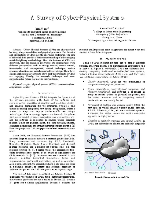
A Survey of Cyber-Physical SystemsJiafu Wan a,ba School of Computer Science and EngineeringSouth China University of Technology,Guangzhou,Chinajiafuwan_76@Hehua Yan*,b,Hui Suo bb College of Information EngineeringGuangdong Jidian PolytechnicGuangzhou,China*Corresponding Author,hehua_yan@Abstract—Cyber Physical Systems(CPSs)are characterized by integrating computation and physical processes.The theories and applications of CPSs face the enormous challenges.The aim of this work is to provide a better understanding of this emerging multi-disciplinary methodology.First,the features of CPSs are described,and the research progresses are summarized from different perspectives such as energy control,secure control, transmission and management,control technique,system resource allocation,and model-based software design.Then three classic applications are given to show that the prospects of CPSs are engaging.Finally,the research challenges and some suggestions for future work are in brief outlined.Keywords-cyber physical systems(CPSs);communications; computation;controlI.I NTRODUCTIONCyber Physical Systems(CPSs)integrate the dynamics of the physical processes with those of the software and communication,providing abstractions and modeling,design, and analysis techniques for the integrated whole[1].The dynamics among computers,networking,and physical systems interact in ways that require fundamentally new design technologies.The technology depends on the multi-disciplines such as embedded systems,computers,communications,etc. and the software is embedded in devices whose principle mission is not computation alone,e.g.cars,medical devices, scientific instruments,and intelligent transportation systems[2]. Now the project for CPSs engages the related researchers very much.Since2006,the National Science Foundation(NSF)has awarded large amounts of funds to a research project for CPSs. Many universities and institutes(e.g.UCB,Vanderbilt, Memphis,Michigan,Notre Dame,Maryland,and General Motors Research and Development Center,etc.)join this research project[3,4].Besides these,the researchers from other countries have started to be aware of significance for CPSs research.In[5-7],the researchers are interested in this domain,including theoretical foundations,design and implementation,real-world applications,as well as education. As a whole,although the researchers have made some progress in modeling,control of energy and security,approach of software design,etc.the CPSs are just in an embryonic stage.The rest of this paper is outlined as follows.Section II introduces the features of CPSs.From different perspectives, the research processes are summarized in Section III.Section IV gives some classic applications.Section V outlines the research challenges and some suggestions for future work and Section VI concludes this paper.II.F EATURES OF CPS SGoals of CPSs research program are to deeply integrate physical and cyber design.The diagrammatic layout for CPSs is shown in Figure1.Obviously,CPSs are different from desktop computing,traditional embedded/real-time systems, today’s wireless sensor network(WSN),etc.and they have some defining characteristics as follows[7-10].∙Closely integrated.CPSs are the integrations of computation and physical processes.∙Cyber capability in every physical component and resource-constrained.The software is embedded inevery embedded system or physical component,andthe system resources such as computing,networkbandwidth,etc.are usually limited.∙Networked at multiple and extreme scales.CPSs,the networks of which include wired/wireless network,WLAN,Bluetooth,GSM,etc.are distributed systems.Moreover,the system scales and device categoriesappear to be highly varied.∙Complex at multiple temporal and spatial scales.In CPSs,the different component has probablyinequable Figure1.Diagrammatic layout for CPSsgranularity of time and spatiality,and CPSs are strictlyconstrained by spatiality and real time.∙Dynamically reorganizing/reconfiguring.CPSs as very complicated systems must have adaptive capabilities.∙High degrees of automation,control loops must close.CPSs are in favor of convenient man-machineinteraction,and the advanced feedback controltechnologies are widely applied to these systems.∙Operation must be dependable,certified in some cases.As a large scale/complicated system,the reliability andsecurity are necessary for CPSs.III.R EASEARCH P ROCESSSince2007,American government has treated CPSs as a new development strategy.Some researchers from various countries discussed the related concepts,technologies, applications and challenges during CPSweek and the international conference on CPS subject[11].The results of this research mainly concentrate in the following respects[7]. A.Energy ControlOne of the features of CPSs is distributed system.Though the vast majority of devices in CPSs need less energy,the energy supply is still a great challenge because the demand and supply of energy is inconvenient.In[12],a control strategy is proposed for realizing best trade-off between satisfying user requests and energy consumption in a data center.In[13-15],these papers concern the basic modeling of cyber-based physical energy systems.A novel cyber-based dynamic model is proposed in which a resulting mathematical model greatly depends on the cyber technologies supporting the physical system.F.M.Zhang et al [16]design optimal and adaptive discharge profile for a square wave impulsive current to achieve maximum battery life.J. Wei et al and C.J.Xue et al[17,18]develop an optimal lazy scheduler to manage services with minimum energy expenditure while not violating time-sensitive constraints.In [19],a peak inlet temperature minimization problem is formulated to improve the energy efficiency.J.R.Cao et al[20] present a clustering architecture in order to obtain good performance in energy efficiency.B.Secure ControlNow,the research for secure control mainly includes key management,identity authentication,etc.In[21],the existing security technologies for CPSs are summarized,and main challenges are proposed.C.Singh et al[22]explore the topic of the reliability assurance of CPSs and possibly stimulate more research in this area.T.T.Gamage et al[23]give a general theory of event compensation as an information flow security enforcement mechanism for CPSs.Then a case study is used to demonstrate this concept.In[24],a certifcateless signature scheme for mobile wireless CPSs is designed and validated.Y.Zhang et al[25]present an adaptive health monitoring and management system model that defines the fault diagnosis quality metrics and supports diagnosis requirement specifications.J.Wei et al[26]exploit message scheduling solutions to improve security quality of wireless networks for mission-critical cyber-physical applications.C.Transmission and ManagementCPSs need to conduct the transmission and management of multi-modal data generated by different sensor devices.In[27], a novel information-centric approach for timely,secure real-time data services in CPSs is proposed.In order to obtain the crucial data for optimal environment abstraction,L.H.Kong et al[28]study the spatio-temporal distribution of CPS nodes.H. Ahmadi et al[29]present an innovative congestion control mechanism for accurate estimation of spatio-temporal phenomena in wireless sensor networks performing monitoring applications.A dissertation on CPSs discusses the design, implementation,and evaluation of systems and algorithms that enable predictable and scalable real-time data services for CPS applications[30].Now,the exiting results are still rare,and there are many facets to be studied.D.Model-based Software DesignNow,the main model-based software design methods include Model Driven Development(MDD)(e.g.UML), Model-Integrated Computing(MIC),Domain-Specific Modeling(DSM),etc[31,32].An example,abstractions in the design flow for DSM,is shown in Figure2.These methods have been widely applied to the embedded system design[34, 35].On the basis of these,some researchers conduct model-based software design for CPSs in the following aspects:event model,physical model,reliability and real-time assurance,etc.Figure2.Abstractions in the design flow for DSM[33]1)Event model.E.A.Lee et al[36]make a case that the time is right to introduce temporal semantics into programming models for CPSs.A programming model called programming temporally-integrated distributed embedded systems(PTIDES) provides a coordination language rooted in discrete-event semantics,supported by a lightweight runtime framework and tools for verifying concurrent software components.In[37],a concept lattice-based event model for CPSs is proposed.This model not only captures the essential information about events in a distributed and heterogeneous environment,but it alsoPlatform mapping Abstractions are linkedthrough refinementrelationsAbstraction layers allowthe verification ofdifferent propertiesPlatform mappingAbstraction layersdefine platformsallows events to be composed across different boundaries of different components and devices within and among both cyber and physical domains.In addition,A CPS architecture along with a novel event model for CPS is developed[38].2)Physical model.In[39],a methodology for automatically abstracting models of CPSs is proposed.The models are described using a user-defined language inspired by assembly code.For mechanical systems,Y.Zhu et al[40]show how analytical models of a particular class of physical systems can be automatically mapped to executable simulation codes.S.Jha et al[41]present a new approach to assist designers by synthesizing the switching logic,given a partial system model, using a combination of fixpoint computation,numerical simulation,and machine learning.This technique quickly generates intuitive system models.3)Reliability and real-time assurance. E. A.Lee[42] emphasizes the importance of security,reliability and real-time assurance in CPSs,and considers the effective orchestration of software and physical processes requires semantic models. From the perspective of soft real-time and hard real-time,U. Kremer[43]conducts the research that the role of time in CPS applications has a fundamental impact on the design and requirements.In CPSs,the heterogeneity causes major challenges for compositional design of large-scale systems including fundamental problems caused by network uncertainties,such as time-varying delay,jitter,data rate limitations,packet loss and others.To address these implementation uncertainties,X.Koutsoukos et al[44]propose a passive control architecture.For improving reliability,T.L. Crenshaw et al[45]describe a simplex reference model to assist developers with CPS architectures which limit fault-propagation.A highly configurable and reusable middleware framework for real-time hybrid testing is provided in[46].Though the model-based software design has an early start, the present development of CPSs progresses at a fast enough rate to provide a competitive challenge.E.Control TechniqueCompared with other control applications,the control technique for CPSs is still at an elementary stage.F.M.Zhang et al[2]develop theoretical results in designing scheduling algorithms for control applications of CPS to achieve balances among robustness,schedulability and power consumption. Moreover,an inverted pendulum as a study object is designed to validate the proposed theory.N.Kottenstette et al[47] describe a general technique:passivity and a particular controller structure involving the resilient power junction.In [48],a design and implementation of CPSs for neutrally controlled artificial legs is proposed.In[49],J.L.Ny et al approach the problem of certifying a digital controller implementation from an input-output,robust control perspective.F.System Resource AllocationUntil now,the relative research for system resource allocation mainly focuses on embedded/real-time systems, networked control systems,WSN,etc[50-52].Towards the complicated CPSs,this work is in the beginning stage.V.Liberatore[53]gives a new train of thought on bandwidth allocation in CPSs.In[54],the model dynamics are presented to express the properties of both software and hardware of CPSs,which is used to do resource allocation.K.W.Li et al [55]research the problem of designing a distributed algorithm for joint optimal congestion control and channel assignment in the multi-radio multi-channel networks for CPSs.The ductility metric is developed to characterize the overload behavior of mixed-criticality CPSs in[56].IV.C LASSIC A PPLICATIONSApplications of CPSs include medical devices and systems, assisted living,traffic control and safety,advanced automotive systems,process control,energy conservation,environmental control avionics and aviation software,instrumentation,critical infrastructure(e.g.power,water),distributed robotics,weapons systems,manufacturing,distributed sensing command and control,smart structures,biosystems,communications systems, etc.[9,10].The classic application architecture of CPSs is described in[38].Now,some application cases for CPSs have been conducted in[57-64].Here,three examples(Health Care and Medicine,Intelligent Road and Unmanned Vehicle,and Electric Power Grid)are used to illuminate the classic applications of CPSs[8,9].A.Health Care and MedicineThe domain of health care and medicine includes national health information network,electronic patient record initiative, home care,operating room,etc.some of which are increasingly controlled by computer systems with hardware and software components,and are real-time systems with safety and timing requirements.A case of CPSs,an operating room,is shown in Figure3.Figure3.A case of CPSs:An operating room[8,9]B.Electric Power GridThe power electronics,power grid,and embedded control software form a CPS,whose design is heavily influenced by fault tolerance,security,decentralized control,and economic/ ethical social aspects[65].In[8,9],a case of CPSs,electric power grid,is given as shown in Figure4.Figure4.A case of CPSs:Electric power grid[8,9]C.Integrate Intelligent Road with Unmanned VehicleWith the development of sensor network,embedded systems,etc.some new solutions can be applied to unmanned vehicle.We are conducting a program that intelligent road and unmanned vehicle are integrated in the form of CPSs.Figure5 shows another case of CPSs:Integrate intelligent road with unmanned vehicle.Figure5.A case of CPSs:Integrate intelligent road with unmanned vehicleV.R ESEARCH C HALLENGESCPSs as a very active research field,a variety of questions need to be solved,at different layers of the architecture and from different aspects of systems design,to trigger and to ease the integration of the physical and cyber worlds[66].In[10, 42,66-68],the research challenges are mainly summarized as follows:1)Control and hybrid systems.A new mathematical theory must merge event-based systems with time-based systems for feedback control.This theory also must be suitable for hierarchies involving asynchronous dynamics at different time scales and geographic scope.2)Sensor and mobile networks.In practical applications, the need for increased system autonomy requires self-organizing/reorganizing mobile networks for CPSs.Gathering and refining critical information from the vast amount of raw data is essential.3)Robustness,reliability,safety,and security.It is a critical challenge because uncertainty in the environment,security attacks,and errors in physical devices make ensuring overall system robustness,security,and safety.Exploiting the physical nature of CPS by leveraging location-based,time-based and tag-based mechanisms is to realize security solutions.4)Abstractions.This aspect includes real-time embedded systems abstractions and computational abstractions,which needs new resource allocation scheme to ensure that fault tolerance,scalability,optimization,etc.are achieved.New distributed real-time computing and real-time group communication methods are needed.In addition,the physical properties also should be captured by programming abstractions.5)Model-based development.Though there several existing model-based development methods,they are far from meeting demands in puting and communications,and physical dynamics must be abstracted and modeled at different levels of scale,locality,and time granularity.6)Verification,validation,and certification.The interaction between formal methods and testing needs to be established. We should apply the heterogeneous nature of CPS models to compositional verification and testing methods.VI.C ONCLUSIONSIn the last few years,this emerging domain for CPSs has been attracting the significant interest,and will continue for the years to come.In spite of rapid evolution,we are still facing new difficulties and severe challenges.In this literature, we concisely review the existing research results that involve energy control,secure control,model-based software design transmission and management,control technique,etc.On this basis,some classic applications used to show the good prospects.Then,we propose several research issues and encourage more insight into this new field.A CKNOWLEDGMENTThe authors would like to thank the National Natural Science Foundation of China(No.50875090,50905063), National863Project(No.2009AA4Z111),Key Science and Technology Program of Guangdong Province(No. 2010B010700015),China Postdoctoral Science Foundation (No.20090460769)and Open Foundation of Guangdong Key Laboratoryof Modern Manufacturing Technology(No. GAMTK201002)for their support in this research.R EFERENCES[1]Available at:/cps/.[2] F.M.Zhang,K.Szwaykowska,W.Wolf,and V.Mooney,“Taskscheduling for control oriented requirements for Cyber-Physical Systems,”in Proc.of2008Real-Time Systems Symposium,2005,pp.47-56.[3]Available at:/news/17248-nsf-funds-cyber-physical-systems-project/.[4]J.Sprinkle,U.Arizona,and S.S.Sastry,“CHESS:Building a Cyber-Physical Agenda on solid foundations,”Presentation Report,Apr2008.[5]Available at:/.[6]Available at:/gdcps.html.[7]J.Z.Li,H.Gao,and B.Yu,“Concepts,features,challenges,andresearch progresses of CPSs,”Development Report of China Computer Science in2009,pp.1-17.[8]R.Rajkumar,“CPS briefing,”Carnegie Mellon University,May2007.[9] B.H.Krogh,“Cyber Physical Systems:the need for new models anddesign paradigms,”Presentation Report,Carnegie Mellon University. [10] B.X.Huang,“Cyber Physical Systems:A survey,”Presentation Report,Jun2008.[11]Available at:/.[12]L.Parolini,N.Toliaz,B.Sinopoli,and B.H.Krogh,“A Cyber-PhysicalSystems approach to energy management in data centers,”in Proc.of First International Conference on Cyber-Physical Systems.April2010, Stockholm,Sweden.[13] F.M.Zhang,Z.W.Shi,and W.Wolf,“A dynamic battery model forco-design in cyber-physical systems,”in Proc.of29th IEEE International Conference on Distributed Computing Systems Workshops.2009.[14]M.D.Ilić,L.Xie,U.A.Khan,et al.“Modeling Future Cyber-PhysicalEnergy Systems,”in Proc.of Power and Energy Society General Meeting-Conversion and Delivery of Electrical Energy in the21st Century,2008.[15]M.D.Ilić,L.Xie,U.A.Khan,et al.“Modeling of future Cyber–Physical Energy Systems for distributed sensing and control,”IEEE Transactions on Systems,Man,and Cybernetics-Part A:Systems and Humans,Vol.40,2010,pp.825-838.[16] F.M.Zhang,and Z.W.Shi,“Optimal and adaptive battery dischargestrategies for Cyber-Physical Systems,”in Proc.of Joint48th IEEE Conference on Decision and Control,and28th Chinese Control Conference,2009,Shanghai,China.[17]W.Jiang,G.Z.Xiong,and X.Y.Ding,“Energy-saving servicescheduling for low-end Cyber-Physical Systems,”in Proc.of The9th International Conference for Young Computer Scientists,2008.[18] C.J.Xue,G.L.Xing,Z.H.Yuan,et al.“Joint sleep scheduling andmode assignment in Wireless Cyber-Physical Systems,”in Proc.of29th IEEE International Conference on Distributed Computing Systems Workshops,2009.[19]Q.H.Tang,S.K.S.Gupta,and G.Varsamopoulos,“Energy-efficientthermal-aware task scheduling for homogeneous high-performance computing data centers:A cyber-physical approach,”IEEE Transactions on Parallel and Distributed Systems,Vol.19,2008,pp.1458-1472. [20]J.R.Cao,and H.A.Li,“Energy-efficient structuralized clustering forsensor-based Cyber Physical Systems,”in Proc.of Symposia and Workshops on Ubiquitous,Autonomic and Trusted Computing,2009. [21] A. A.Cárdenas,S.Amin,and S.Sastry,“Secure control:towardssurvivable Cyber-Physical Systems,”in Proc.of The28th International Conference on Distributed Computing Systems Workshops,2008. [22] C.Singh,and A.Sprintson,“Reliability assurance of Cyber-PhysicalPower Systems,”in Conference Proc.,2010.[23]T.T.Gamage,B.M.McMillin,and T.P.Roth,“Enforcing informationflow security properties in Cyber-Physical Systems:A generalized framework based on compensation,”in Proc.of34th Annual IEEE Computer Software and Applications Conference Workshops,2010. [24]Z.Xu,X.Liu,G.Q.Z,et al.“A cert ificateless signature scheme formobile wireless Cyber-Physical Systems,”in Proc.of The28th International Conference on Distributed Computing Systems Workshops, 2008.[25]Y.Zhang,I.L.Yen,F.B.Bastani,et al.“Optimal adaptive systemhealth monitoring and diagnosis for resource constrained Cyber-Physical Systems,”in Proc.of20th International Symposium on Software Reliability Engineering,2009.[26]W.Jiang,W.H.Guo,and N.Sang,“Periodic real-time messagescheduling for confidentiality-aware Cyber-Physical System in wireless networks,”in Proc.of Fifth International Conference on Frontier of Computer Science and Technology,2010.[27]K.D.Kang,and S.H.Son,“Real-time data services for Cyber PhysicalSystems,”in Proc.of28th International Conference on Distributed Computing Systems Workshops,2008.[28]L.H.Kong,D.W.Jiang,and M.Y.Wu,“Optimizing the spatio-temporal distribution of Cyber-Physical Systems for environment abstraction,”in Proc.of International Conference on Distributed Computing Systems,2010.[29]H.Ahmadi,T.F.Abdelzaher,and I.Gupta,“Congestion control forspatio-temporal data in Cyber-Physical Systems,”in Proc.of the1st ACM/IEEE International Conference on Cyber-Physical Systems,2010.[30]W.Kang,“Adaptive real-time data management for Cyber-PhysicalSystems,”PhD Thesis,University of Virginia,2009.[31]Z.M.Song,“Devlopment method of embedded equipment controlsystems based on Model Integrated Computing,”PhD Thesis,South China University of Technology,2007.[32]Available at:/research/MIC.[33]J.Sztipanovits,“Cyber Physical Systems:New challenges for model-based design,”Presentation Report,Vanderbilt University,Apr2008. [34] F.Li,D.Li,J.F.Wan,et al.“Towards a component-based modelintegration approach for embedded computer control system,”in Proc.of International Conference on Computational Intelligence and Security, 2008.[35] D.Li,F.Li,and X.Huang,et al.“A model based integration frameworkfor computer numerical control system development,”Robotics and Computer-Integrated Manufacturing,Vol.26,2010,pp.848-860. [36] E.A.Lee,S.Matic,S.A.Seshia,et al.“The case for timing-centricdistributed software,”in Proc.of29th IEEE International Conference on Distributed Computing Systems Workshops,2009.[37]Y.Tan,M.C.Vuran,and S.Goddard,“A concept lattice-based eventmodel for Cyber-Physical Systems,”in Proc.of CCPS,Apr2010, Stockholm,Sweden.[38]Y.Tan,M.C.Vuran,and S.Goddard,“Spatio-temporal event model forCyber-Physical Systems,”in Proc.of29th IEEE International Conference on Distributed Computing Systems Workshops,2009. [39]R.A.Thacker,K.R.Jones,C.J.Myers,et al.“Automatic abstractionfor verification of Cyber-Physical Systems,”in Proc.of CCPS,Apr2010, Stockholm,Sweden.[40]Y.Zhu, E.Westbrook,J.Inoue,et al.“Mathematical equations asexecutable models of mechanical systems,”in Proc.of CCPS,Apr2010, Stockholm,Sweden.[41]S.Jha,S.Gulwani,S.A.Seshia,et al.“Synthesizing switching logic forsafety and dwell-time requirements,”in Proc.of CCPS,Apr2010, Stockholm,Sweden.[42] E.A.Lee,“Cyber Physical Systems:Design challenges,”in Proc.ofISORC,May,2008,Orlando,USA.[43]U.Kremer,“Cyber-Physical Systems:A case for soft real-time,”Available at:/.[44]X.Koutsoukos,N.Kottenstette,J.Hall,et al.“Passivity-based controldesign for Cyber-Physical Systems,”Available at:http://citeseerx.ist./.[45]T.L.Crenshaw, E.Gunter, C.L.Robinson,et al.“The simplexreference model:Limiting fault-propagation due to unreliable components in Cyber-Physical System architectures,”in Proc.of IEEE International Real-Time Systems Symposium,2008.[46]T.Tidwell,X.Y.Gao,H.M.Huang,et al.“Towards configurable real-time hybrid structural testing:A Cyber-Physical Systems approach,”in Proc.of IEEE International Symposium on Object/Component/Service-Oriented Real-Time Distributed Computing,2009.[47]N.Kottenstette,G.Karsai,and J.Sztipanovits,“A passivity-basedframework for resilient Cyber Physical Systems,”in Proc.of2nd International Symposium on Resilient Control Systems,2009.[48]H.Huang,Y.Sun,Q.Yang,et al.“Integrating neuromuscular and CyberSystems for neural control of artificial legs,”in Proc.of CCPS,Apr 2010,Stockholm,Sweden.[49]J.L.Ny,and G.J.Pappas,“Robustness analysis for the certification ofdigital controller implementations,”in Proc.of CCPS,Apr2010, Stockholm,Sweden.[50]J.F.Wan,D.Li,and P.Zhang,“Key technology of embedded systemimplementation for software-based CNC system,”Chinese Journal of Mechanical Engineering,Vol.23,2010,pp.241-248.[51]J.F.Wan,D.Li,H.H.Yan,and P.Zhang,“Fuzzy feedback schedulingalgorithm based on central processing unit utilization for a software-based computer numerical control system,”Journal of Engineering Manufacture,Vol.224,2010,pp.1133-1143.[52]J.F.Wan,and D.Li,“Fuzzy feedback scheduling algorithm based onoutput jitter in resource-constrained embedded systems,”In Proc.of International Conference on Challenges in Environmental Science and Computer Engineering,March2010,Wuhan,China.[53]V.Liberatore,“Bandwidth allocation in sense-and-respond systems,”Report,Available at:/~vxl11/NetBots/.[54]M.Lindberg,and K.E.Årzén,“Feedback control of cyber-physicalsystems with multi resource dependencies and model uncertainties,”in Proc.of the31st IEEE Real-Time Systems Symposium,Dec2010. [55]K.W.Li,Q.W.Liu,F.R.Wang,et al.“Joint optimal congestioncontrol and channel assignment for multi-radio multi-channel wireless networks in Cyber-Physical Systems,”in Proc.of Symposia and Workshops on Ubiquitous,Autonomic and Trusted Computing,2009. [56]kshmanan,D.Niz,R.Rajkumar,et al.“Resource allocation indistributed mixed-criticality Cyber-Physical Systems,”in Proc.of International Conference on Distributed Computing Systems,2010. [57] D.Dragomirescu,“Cyber-Physical Systems for aeronautic applications,”Presentation Report,2010,University of Toulouse,France.[58] A.M.K.Cheng,“Cyber-Physical Medical and Medication Systems,”inProc.of the28th International Conference on Distributed Computing Systems Workshops,2008.[59]T.Dillon,and E.Chang,“Cyber-Physical Systems as an embodiment ofdigital ecosystems,”in Proc.of4th IEEE International Conference on Digital Ecosystems and Technologies,2010.[60]J.Madden,B.McMillin,and A.Sinha,“Environmental obfuscation of aCyber Physical System-Vehicle example,”in Proc.of34th Annual IEEE Computer Software and Applications Conference Workshops,2010. [61]I.Lee,and O.Sokolsky,“Medical Cyber Physical Systems,”in Proc.ofDAC,2010,Anaheim,California,USA.[62]W.Harrison,J.Moyne,and D.Tilbury,“Virtual fusion:The completeintegration of simulated and actual,”Presentation Report,2008, University of Michigan,USA.[63]M.Li,Y.H.Liu,J.L.Wang,et al.“Sensor network navigation withoutlocations,”in Proc.of IEEE INFOCOM,2009.[64]G.L.Xing,W.J.Jia,Y.F.Du,et al.“Toward ubiquitous video-basedCyber-Physical Systems,”in Proc.of IEEE International Conference on Systems,Man and Cybernetics,2008.[65] B.McMillin,C.Gill,M.L.Crow,et al,“Cyber-Physical Systemsdistributed control-The advanced electric power grid,”Available at: /.[66]L.Sha,S.Gopalakrishnan,X.Liu,et al.“Cyber-Physical Systems:Anew frontier,”in Proc.of IEEE International Conference on Sensor Networks,Ubiquitous,and Trustworthy Computing,2008.[67]M.Broy,“Cyber-Physical Systems:Technological&scientificchallenges,”Presentation Report,2010.[68]R.Rajkumar,I.Lee,L.Sha,et al.“Cyber-Physical Systems-The nextcomputing revolution,”in Proc.of Design Automation Conference,2010, Anaheim,California,USA.。
UML i:The Unified Modeling Language forInteractive ApplicationsPaulo Pinheiro da Silva and Norman W.Paton Department of Computer Science,University of Manchester Oxford Road,Manchester M139PL,England,UK.e-mail:{pinheirp,norm}@AbstractUser interfaces(UIs)are essential components of most software sys-tems,and significantly affect the effectiveness of installed applications.Inaddition,UIs often represent a significant proportion of the code deliveredby a development activity.However,despite this,there are no modellinglanguages and tools that support contract elaboration between UI devel-opers and application developers.The Unified Modeling Language(UML)has been widely accepted by application developers,but not so much byUI designers.For this reason,this paper introduces the notation of theUnified Modelling Language for Interactive Applications(UML i),that ex-tends UML,to provide greater support for UI design.UI elements elicitedin use cases and their scenarios can be used during the design of activitiesand UI presentations.A diagram notation for modelling user interfacepresentations is introduced.Activity diagram notation is extended to de-scribe collaboration between interaction and domain objects.Further,acase study using UML i notation and method is presented.1IntroductionUML[9]is the industry standard language for object-oriented software design. There are many examples of industrial and academic projects demonstrating the effectiveness of UML for software design.However,most of these success-ful projects are silent in terms of UI design.Although the projects may even describe some architectural aspects of UI design,they tend to omit important aspects of interface design that are better supported in specialist interface de-sign environments[8].Despite the difficulty of modelling UIs using UML,it is becoming apparent that domain(application)modelling and UI modelling may occur simultaneously.For instance,tasks and domain objects are interde-pendent and may be modelled simultaneously since they need to support each other[10].However,task modelling is one of the aspects that should be consid-ered during UI design[6].Further,tasks and interaction objects(widgets)areinterdependent as well.Therefore,considering the difficulty of designing user interfaces and domain objects simultaneously,we believe that UML should be improved in order to provide greater support for UI design[3,7].This paper introduces the UML i notation which aims to be a minimal exten-sion of the UML notation used for the integrated design of applications an their user interfaces.Further,UML i aims to preserve the semantics of existing UML constructors since its notation is built using new constructors and UML exten-sion mechanisms.This non-intrusive approach of UML i can be verified in[2], which describes how the UML i notation introduced in this paper is designed in the UML meta-model.UML i notation has been influenced by model-based user interface develop-ment environment(MB-UIDE)technology[11].In fact,MB-UIDEs provide a context within which declarative models can be constructed and related,as part of the user interface design process.Thus,we believe that the MB-UIDE technology offers many insights into the abstract description of user interfaces that can be adapted for use with the UML technology.For instance,MB-UIDE technology provides techniques for specifying static and dynamic aspects of user interfaces using declarative models.Moreover,as these declarative models can be partially mapped into UML models[3],it is possible to identify which UI aspects are not covered by UML models.The scope of UML i is restricted to form-based user interfaces.However, form-based UIs are widely used for data-intensive applications such as database system applications and Web applications and UML i can be considered as a baseline for non-form-based UI modelling.In this case,modifications might be required in UML i for specifying a wider range of UI presentations and tasks.To introduce the UML i notation,this paper is structured as follows.MB-UIDE’s declarative user interface models are presented in terms of UML i dia-grams in Section2.Presentation modelling is introduced in Section3.Activity modelling that integrates use case,presentation and domain models is presented in Section4.The UML i method is introduced in Section5when a case study ex-emplifying the use of the UML i notation is presented along with the description of the method.Conclusions are presented in Section6.2Declarative User Interface ModelsA modelling notation that supports collaboration between UI developers and application developers should be able to describe the UI and the application at the same time.From the UI developer’s point of view,a modelling notation should be able to accommodate the description of users requirements at appro-priate levels of abstraction.Thus,such a notation should be able to describe abstract task specifications that users can perform in the application in order to achieve some goals.Therefore,a user requirement model is required to describe these abstract tasks.Further,UI sketches drawn by users and UI developers can help in the elicitation of additional user requirements.Therefore,an abstract presentation model that can present early design ideas is required to describethese UI ter in the design process,UI developers could also refine abstract presentation models into concrete presentation models,where widgets are selected and customised,and their placement(layout)is decided.From the application developer’s point of view,a modelling notation that integrates UI and application design should support the modelling of application objects and actions in an integrated way.In fact,the identification of how user and application actions relate to a well-structured set of tasks,and how this set of tasks can support and be supported by the application objects is a challenging activity for application designers.Therefore,a task model is required to describe this well-structured set of tasks.The task model is not entirely distinct from the user requirement model.Indeed,the task model can be considered as a more structured and detailed view of the user requirement model.The application objects,or at least their interfaces,are relevant for UI de-sign.In fact,these interfaces are the connection points between the UI and the underlying application.Therefore,the application object interfaces compose an application model.In an integrated UI and application development environ-ment,an application model is naturally produced as a result of the application design.UML i aims to show that using a specific set of UML constructors and dia-grams,as presented in Figure1,it is possible to build declarative UI models. Moreover,results of previous MB-UIDE projects can provide experience as to how the declarative UI models should be inter-related and how these models can be used to provide a declarative description of user interfaces.For instance, the links(a)and(c)in Figure1can be explained in terms of state objects,as presented in Teallach[5].The link(d)can be supported by techniques from TRI-DENT[1]to generate concrete presentations.In terms of MB-UIDE technology there is not a common sense of the models that might be used for describing a UI.UML i does not aim to present a new user interface modelling proposal,but to reuse some of the models and techniques proposed for use in MB-UIDEs in the context of UML.Figure1:UML i declarative user interface models.3User Interface DiagramUser interface presentations,the visual part of user interfaces,can be modelled using object diagrams composed of interaction objects,as shown in Figure2(a). These interaction objects are also called widgets or visual components.The selection and grouping of interaction objects are essential tasks for modelling UI presentations.However,it is usually difficult to perform these tasks due to the large number of interaction objects with different functionalities provided by graphical environments.In a UML-based environment,the selection and grouping of interaction objects tends to be even more complex than in UI de-sign environments because UML does not provide graphical distinction between domain and interaction objects.Further,UML treats interaction objects in the same way as any other objects[3].For instance,in Figure2(a)it is not easy to see that the Results Displayer is contained by the SearchBookUI FreeContainer. Considering these presentation modelling difficulties,this section introduces the UML i user interface diagram,a specialised object diagram used for the concep-tual modelling of user interface presentation.(a)(b)Figure2:An abstract presentation model for the SearchBookUI can be modelled as an object diagram of UML,as presented in(a).The same presentation can alternatively be modelled using the UML i user interface diagram,as presented in(b).3.1User Interface Diagram NotationThe SearchBookUI abstract presentation modelled using the user interface dia-gram is presented in Figure2(b).The user interface diagram is composed of six constructors that specify the role of each interaction object in a UI presentation.•FreeContainers,•Containers,,are rendered as a pair of semi-overlapped triangles pointing to the right.They are responsible for receiving information from users in the form of events.Graphically,Containers,Inputters,Displayers,Editors and ActionInvokers must be placed into a FreeContainer.Additionally,the overlapping of the bor-ders of interaction objects is not allowed.In this case,the“internal”lines of Containers and FreeContainers,in terms of their two-dimensional representa-tions,are ignored.3.2From an Abstract to a Concrete PresentationThe complexity of user interface presentation modelling can be reduced by work-ing with a restricted set of abstract interaction objects,as specified by the user interface diagram notation.However,a presentation modelling approach as proposed by the UML i user interface diagram is possible since form-based pre-sentations respect the Abstract Presentation Pattern1(APP)in Figure3.Thus, a user interface presentation can be described as an interaction object acting as a FreeContainer.The APP also shows the relationships between the abstract interaction objects.As we can see,the APP is environment-independent.In fact,a UI presen-tation described using the user interface diagram can be implemented by any object-oriented programming language,using several toolkits.Widgets should be bound to the APP in order to generate a concrete presentation model.In this way,each widget should be classified as a FreeContainer,Container, Inputter,Displayer,Editor or ActionInvoker.The binding of widgets to the APP can be described using UML[3].Widget binding is not efficient to yield afinal user interface implementation. In fact,UML i is used for UI modelling and not for implementation.However, we believe that by integrating UI builders with UML i-based CASE tools we canFigure3:The Abstract Presentation Patternproduce environments where UIs can be modelled and developed in a system-atic way.For instance,UI builder facilities may be required for adjusting UI presentation layout and interaction object’s colour,size and font.4Activity Diagram ModellingUML interaction diagrams(sequence and collaboration diagrams)are used for modelling how objects collaborate.Interaction diagrams,however,are limited in terms of workflow modelling since they are inherently sequential.Therefore, concurrent and repeatable workflows,and especially those workflows affected by users decisions,are difficult to model and interpret from interaction diagrams.Workflows are easily modelled and interpreted using activity diagrams.In fact,Statechart constructors provide a graphical representation for concurrent and branching workflows.However,it is not so natural to model object col-laboration in activity diagrams.Improving the ability to describe object col-laboration and common interaction behaviour,UML i activity diagrams provide greater support for UI design than UML activity diagrams.This section explains how activities can be modelled from use cases,how activity diagrams can be simplified in order to describe common interactive behaviours,and how interaction objects can be related to activity diagrams.4.1Use Cases and Use Case ScenariosUse case diagrams are normally used to identify application functionalities. However,use case diagrams may also be used to identify interaction activi-ties.For instance,a communicates association between a use case and an actor indicates that the actor is interacting with the use case.Therefore,forexample,in Figure4the CollectBook use case cannot identify an interaction activity since its association with Borrower is not a communicates associa-tion.Indeed,the CollectBook use case identifies a functionality not supported by the application.Figure4:A use case diagram for the BorrowBook use case with its component use cases.Use case scenarios can be used for the elicitation of actions[12].Indeed,ac-tions are identified by scanning scenario descriptions looking for verbs.However, actions may be classified as Inputters,Displayers,Editors or ActionInvokers. For example,Figure5shows a scenario for the SearchBook use case in Figure4. Three interaction objects can be identified in the scenario:∇providingthat specifies some query details;and displaysits title,authors,year,or a combination of this information.Addi-tionally,John can∇specifythe details of the matching books,if any.Figure5:A scenario for the SearchBook use case.4.2From Use Cases to ActivitiesUML i assumes that a set of activity diagrams can describe possible user interac-tions since this set can describe possible application workflows from application entry points.Indeed,transitions in activity diagrams are inter-object transi-tions,such as those transitions between interaction and domain objects that can describe interaction behaviours.Based on this assumption,those activity diagrams that belong to this set of activity diagrams can be informally classified as interaction activity diagrams.Activities of interaction activity diagrams can also be informally classified as interaction activities.The difficulty with this classification,however,is that UML does not specify any constructor for mod-elling application entry points.Therefore,the process of identifying in which activity diagram interactions start is unclear.The initial interaction state constructor used for identifying an application’s entry points in activity diagrams is introduced in UML i.This constructor is rendered as a solid square,,and it is used as the UML initial pseudo-state[9], except that it cannot be used within any state.A top level interaction activ-ity diagram must contain at least one initial interaction state.Figure6 shows a top level interaction activity diagram for a library application.Figure6:Modelling an activity diagram from use cases using UML i.Use cases that communicate directly with actors are considered candidate interaction activities in UML i.Thus,we can define a top level interaction ac-tivity as an activity which is related to a candidate interaction activity.This relationship between a top level interaction activity and a candidate interaction activity is described by a realisation relationship,since activity diagrams can describe details about the behaviour of candidate interaction activities.The diagram in Figure6is using the UML i activity diagram notation explained in the next section.However,we can clearly see in the diagram which top level interaction activity realises which candidate interaction activity.For instance, the SearchBook activity realises the SearchBook candidate interaction activity modelled in the use case diagram in Figure4.In terms of UI design,interaction objects elicited in scenarios are primitive interaction objects that must be contained by FreeContainers(see the APP in Figure3).Further,these interaction objects should be contained by FreeCon-tainers associated with top-level interaction activities,such as the SearchBookUI FreeContainer in Figure6,for example.Therefore,interaction objects elicited from scenarios are initially contained by FreeContainers that are related to top-level interaction through the use of a presents objectflow,as described in Section4.4.In that way,UI elements can be imported from use case diagrams to activity diagrams.For example,the interaction objects elicited in Figure5 are initially contained by the SearchBookUI presented in Figure6.4.3Selection StatesStatechart constructors for modelling transitions are very powerful since they can be combined in several ways,producing many different compound transi-tions.In fact,simple transitions are suitable for relating activities that can be executed sequentially.A combination of transitions,forks and joins is suitable for relating activities that can be executed in parallel.A combination of transitions and branches is suitable for modelling the situation when only one among many activities is executed(choice behaviour).However,for the de-signing of interactive applications there are situations where these constructors can be held to be rather low-level,leading to complex models.The following behaviours are common interactive application behaviours,but usually result in complex models.•The order independent behaviour is presented in Figure7(a).There, activities A and B are called selectable activities since they can be acti-vated in either order on demand by users who are interacting with the application.Thus,every selectable activity should be executed once dur-ing the performance of an order independent behaviour.Further,users are responsible for selecting the execution order of selectable activities.An or-der independent behaviour should be composed of one or more selectable activities.An object with the execution history of each selectable activity (SelectHist in Figure7(a))is required for achieving such behaviour.•The optional behaviour is presented in Figure7(b).There,users can execute any selectable activity any number of times,including none.In this case,users should explicitly specify when they arefinishing the Select activity.Like the order independent behaviour,the optional behaviour should be composed of one or more selectable activities.•The repeatable behaviour is presented in Figure7(c).Unlike the order independent and optional behaviours,a repeatable behaviour should have only one associated activity.A is the associated activity of the repeat-able behaviour in Figure7.Further,a specific number of times that the associated activity can be executed should be specified.In the case of the diagram in Figure7(c),this number is identified by the value of X.An optional behaviour with one selectable activity can be used when aselectable activity can be executed an unspecified number oftimes.(a)(b)(c)Figure7:The UML modelling of three common interaction application be-haviours.An order independent behaviour is modelled in(a).An optional behaviour is modelled in(b).A repeatable behaviour is modelled in(c).As optional,order independent and repeatable behaviours are common in interactive systems[5],UML i proposes a simplified notation for them.The no-tation used for modelling an order independent behaviour is presented in Fig-ure8(a).There we can see an order independent selector,rendered as a circle overlying a plus signal,⊕,connected to the activities A and B by return transi-tions,rendered as solid lines with a single arrow at the selection state end and a double arrow at the selectable activity end.The order independent selector identifies an order independent selection state.The double arrow end of return transitions identify the selectable activities of the selection state.The distinc-tion between the selection state and its selectable activities is required when selection states are also selectable activities.Furthermore,a return transition is equivalent of a pair of Statechart transitions,one single transition connecting the selection state to the selectable activity,and one non-guarded transition connecting the selectable activity to the selection state,as previously modelled in Figure7(a).In fact,the order independent selection state notation can beconsidered as a macro-notation for the behaviour described in Figure7(a).(b)The notations for modelling optional and repeatable behaviours are similar, in terms of structure,to the order independent selection state.The main dif-ference between the notation of selection states is the symbols used for their selectors.The optional selector which identifies an optional selection state is rendered as a circle overlaying a minus signal, .The repeatable selector which identifies a repeatable selection state2is rendered as a circle overlaying a times signal,⊗.The repeatable selector additionally requires a REP constraint,as shown in Figure8(c),used for specifying the number of times that the asso-ciated activity should be repeated.The value X in this REP constraint is the X parameter in Figure7(c).The notations presented in Figures8(b)and8(c) can be considered as macro-notations for the notation modelling the behaviours presented in Figures7(b)and7(c).4.4Interaction Object BehaviourObjects are related to activities using objectflows.Objectflows are basically used for indicating which objects are related to each activity,and if the objects are generated or used by the related activities.Objectflows,however,do not describe the behaviour of related objects within their associated activities.Ac-tivities that are action states and that have objectflows connected to them can describe the behaviour of related objects since they can describe how methods may be invoked on these objects.Thus,a complete decomposition of activities into action states may be required to achieve such object behaviour description. However,in the context of interaction objects,there are common functions that do not need to be modelled in detail to be understood.In fact,UML i pro-videsfive specialised objectflows for interaction objects that can describe these common functions that an interaction object can have within a related activity. These objectflows are modelled as stereotyped objectflows and explained as follows.•An interacts objectflow relates a primitive interaction object to an action state,which is a primitive activity.Further,the objectflow indi-cates that the action state involved in the objectflow is responsible for an interaction between a user and the application.This can be an interaction where the user is invoking an object operation or visualising the result of an object operation.The action states in the SpecifyBookDetails activity, Figure9,are examples of Inputters assigning values to some attributes of the SearchQuery domain object.The Results in Figure9is an exam-ple of a Displayer for visualising the result of SearchQuery.SearchBook().As can be observed,there are two abstract operations specified in the APP (Figure3)that have been used in conjunction with these interaction ob-jects.The setValue()operation is used by Displayers for setting the values that are going to be presented to the users.The getValue()op-eration is used by Inputters for passing the value obtained from the users to domain objects.Figure9:The SearchBook activity.•A presents objectflow relates a FreeContainer to an activity.It spec-ifies that the FreeContainer should be visible while the activity is ac-tive.Therefore,the invocation of the abstract setVisible()operation of the FreeContainer is entirely transparent for the developers.In Figure9 the SearchBookUI FreeContainer and its contents are visible while the SearchBook activity is active.•A confirms objectflow relates an ActionInvoker to a selection state. It specifies that the selection state hasfinished normally.In Figure9the event associated with the“Search”directly related to it.The optional selection state in the SpecifyBookDetails relies on theSpecifyDetails a user is also confirming the optional selection state in SpecifyBookDetails.•A cancels objectflow relates an ActionInvoker to any composite ac-tivity or selection state.It specifies that the activity or selection state has notfinished normally.Theflow of control should be re-routed to a previ-ous state.Theinteraction objects of abstract use cases are also very abstract,and may not be useful for exporting to activity diagrams.Therefore,the UML i method suggests that interaction objects can be elicited from less abstract use cases.Step3Candidate interaction activity identification.Candidate interaction activities are use cases that communicate directly with actors,as described in Section4.1.Step4Interaction activity modelling.A top level interaction activity diagram can be designed from identified candidate interaction activities.A top level in-teraction activity diagram must contain at least one initial interaction state. Figure6shows a top level interactive activity diagram for the Library case study.Top level interaction activities may occasionally be grouped into more abstract interaction activities.In Figure6,many top level interaction activ-ities are grouped by the SelectFunction activity.In fact,SelectFunction was created to gather these top level interaction activities within a top level interaction activity diagram.However,the top level interaction activities,and not the SelectFunction activity,remain responsible for modelling some of the major functionalities of the application.The process of moving from candidate interaction activities to top level interaction activities is described in Section4.2. Step5Interaction activity refining.Activity diagrams can be refined,decom-posing activities into action states and specifying objectflows.Activities can be decomposed into sub-activities.The activity decomposition can continue until the action states(leaf activities)are reached.For instance, Figure9presents a decomposition of the SearchBook activity introduced in Figure6.The use of interacts objectflows relating interaction objects to action states indicates the end of this step.Step6User interface er interface diagrams can be refined to support the activity diagrams.User interface modelling should happen simultaneously with Step5in order to provide the activity diagrams with the interaction objects required for describing action states.There are two mechanisms that allow UI designers to refine a conceptual UI presentation model.•The inclusion of complementary interaction objects allows designers to improve the user’s interaction with the application.•The grouping mechanism allows UI designers to create groups of interac-tion objects using Containers.At the end of this step it is expected that we have a conceptual model of the user interface.The interaction objects required for modelling the user interface were identified and grouped into Containers and FreeContainers.Moreover,the interaction objects identified were related to domain objects using action states and UML iflow objects.Step7Concrete presentation modelling.Concrete interaction objects can be bound to abstract interaction objects.The concrete presentation modelling begins with the binding of concrete inter-action objects(widgets)to the abstract interaction objects that are specified by the APP.Indeed,the APP isflexible enough to map many widgets to each abstract interaction object.Step8Concrete presentation refier interface builders can be used for refining user interface presentations.The widget binding alone is not enough for modelling a concrete user interface presentation.Ergonomic rules presented as UI design guidelines can be used to automate the generation of the user interface presentation.Otherwise,the concrete presentation model can be customised manually,for example,by using direct manipulation.6ConclusionsUML i is a UML extension for modelling interactive applications.UML i makes extensive use of activity diagrams during the design of interactive applications. Well-established links between use case diagrams and activity diagrams explain how user requirements identified during requirements analysis are described in the application design.The UML i user interface diagram introduced for mod-elling abstract user interface presentations simplifies the modelling of the use of visual components(widgets).Additionally,the UML i activity diagram notation provides a way for modelling the relationship between visual components of the user interface and domain objects.Finally,the use of selection states in activity diagrams provides a simplification for modelling interactive systems.The reasoning behind the creation of each new UML i constructor and con-straint has been presented throughout this paper.The UML i notation was en-tirely modelled in accordance to the UML i meta-model specifications[2].This demonstrates that UML i is respecting its principle of being a non-intrusive ex-tension of UML,since the UML i meta-model does not replace the functionalities of any UML constructor[2].Moreover,the presented case study indicates that UML i may be an appropriate approach in order to improve UML’s support for UI design.In fact,the UIs of the presented case study were modelled us-ing fewer and simpler diagrams than using standard UML diagrams only,as described in[3].As the UML i meta-model does not modify the semantics of the UML meta-model,UML i is going to be implemented as a plug-in feature of the ARGO/UML case tool.This implementation of UML i will allow further UML i evaluations using more complex case studies.Acknowledgements.Thefirst author is sponsored by Conselho Nacional de Desenvolvimento Cient´ıfico e Tecnol´o gico-CNPq(Brazil)–Grant200153/98-6.。

关于:IATF为了加强TS16949的价值和可信度,通过发布认证导则第四版“提升认证门槛”1. Site extensions制造现场延伸场地Site extensions as defined previously will no longer exist as part of the ISO/TS 16949 Certification Scheme.制造现场延伸场地将不再存在于ISO/TS 16949 认证方案中IATF will withdraw, and therefore make obsolete, the current possibility to include site extensions effective 1st of April 2014. IATF 将从2014 年4 月1 日开始撤销并从而废除, 目前包含现场延伸场地的的认证Clients with an existing manufacturing site extension will need to transition this site extension to a single site between the time period of 1st of April 2014 – 1st of April 2015. 现有制造现场延伸场地的客户将需要按CB 公告2013-006 所述流程在2014 年4 月1日至2015 年4 月1 日期间将其转换为单个现场.Different Choices for transition”您可以选择下列方案之一进行“转换”:1 Single Site Certification单现场认证2 Corporate Scheme, if comply with Rules 5.3TÜV Rheinland Greater ChinaPage 2 of 7如果满足认证规则5.3 条款关于“集团审核方案”的要求,可与现在主证书相结合,形成“集团审核方案”。

Models of Software Systems Fall 2004ObjectivesScientific foundations for software engineering depend on the use of precise, abstract models and logics for characterizing and reasoning about properties of software systems. There are a number of basic models and logics that over time have proven to be particularly important and pervasive in the study of software systems. This course is concerned with that body of knowledge. It considers many of the standard models for representing sequential and concurrent systems, such as state machines, algebras and traces. It shows how different logics can be used to specify properties of software systems, such as functional correctness, deadlock freedom, and internal consistency. Concepts such as composition mechanisms, abstraction relations, invariants, non-determinism, and inductive and denotational descriptions are recurrent themes throughout the course.By the end of the course you should be able to understand the strengths and weaknesses of certain models and logics, including state machines, algebraic and trace models, and temporal logics. You should be able to apply this understanding to select and describeabstract formal models for certain classes of systems. Further, you should be able to reason formally about the elementary properties of modeled systems.OrganizationLectures. Classes meet Monday & Wednesday, 5:30-6:50 am, in Newell-Simon 1305.Communication. We will be using the CMU Blackboard System this year for distributing most course materials, providing a general course bulletin board, and keeping track of student email addresses. In addition you can useOffice Hours: The instructor and the TAs have weekly office hours, listed above. We are also available other times by appointment.1.Email: We welcome email about the course at any time.2.Readings. Most lectures will have a reading assignment that we expect you to complete before you come to class. There is one required textbook for the course: Concurrency: State Models and Java Programs, by Magee and Kramer [MK99]. In addition, there is an optional companion text Using Z: Specification, Refinement, and Proof, by Woodcock and Davies [WD96]. This text is available on-line at /.An optional reference book may also be useful: The Z Notation: A Reference Manual, Second Edition, by J. M. Spivey (available on the web through /~mike/zrm). Some readings are in the form of handouts to supplement lectures; other additional readings are technical papers. These will be made available as needed throughout the course. Finally, for supplementary detail, there are a number of books noted in the References section at the end of this document.Homework Assignments. The course is organized around (roughly) weekly homework assignments and a set of three projects. The purpose of the assignments and projects is to give you practice in using the models, logics, and tools of the course. We encourage you to discuss your homework with other students, but the final write-up must be your own work.To give you the most opportunities to learn from the homework assignments, we will allow you to redo problems that didn't receive a passing grade. A redone homework must be turned in at the class following the one on which it is handed back. Problems done correctly the first time will be given more weight in the final grade.Projects. We will be assigning three group projects that are designed to give you a chance to apply the ideas of the course tosemi-realistic case studies. Each project will be completed by a team. Team members are expected to participate equally in the projects.We will distribute a team peer evaluation at the end of the semester.On-line materials. Most of the course materials will be available electronically via the CMU Blackboard System(/blackboard/). You will find copies of the lecture slides, handouts, homework, and readings. It will be your responsibility to make copies of these to bring to class or to use for homework.Some of the course materials have web sites. These are:Using Z: /Concurrency: State Models and Java Programs: /concurrency/The Z Notation: /~mike/zrm/PhD Option. Students taking the course for PhD credit students will be required to complete a course project. This project is described in separate handout.Exams. There will be a (take-home) mid-term (handed out Wednesday, October 20, due back Friday, October 22 by 5:00 p.m.) and a formal (in-class) final examination. Both exams will be open-book.Grading. The course grade will be determined as a combination of five factors: homework assignments (30%), projects (30%), midterm exam (15%), and final exam (25%). Final grades may be adjusted based on instructors judgment.Bold refers to Using Z [WD96].*Marks classes that follow a holiday.。

计算机软件与理论专业课程介绍(P39-P71)课程编号:S0115010812001课程名称:自然辩证法课程英文名称:Politics学分:2 周学时:2 总学时:36课程性质:工程硕士学位必修适用专业:软件工程、计算机软件与理论教学内容及基本要求:教学内容:掌握近代科学的诞生情况;尤其了解当代自然科学对社会正在产生的深远影响。
教学要求:主要通过课堂教学的方式,使学生理解自然科学的起源及其发展规律,了解自然科学与社会的相互关系,了解著名科学家的生平及工作方式。
考核方式及要求:考试学习本课程的前期课程要求:无教材及主要参考书目、文献与资料:1、《宗教与现代科学的兴起》,R. 霍伊卡著,四川人民出版社,1991年。
2、《科学的历程》,(上下两册)吴国盛著,湖南科技出版社,1997年。
3、《进化的阶梯》,陈蓉霞著,中国社会科学出版社,1996年。
4、《科学与近代世界》,N. 怀特海著,商务印书馆,1989年。
5、《意大利文艺复兴时期的文化》,布克哈特著,商务印书馆,1991年。
填写人:陈蓉霞审核人:姜宁康课程编号:S1*******、 S1*******课程名称:英语口译翻译课程英文名称:English Interpretation学分:2 周学时:2 总学时:72课程性质:工程硕士学位适用专业:软件工程、计算机软件与理论教学内容及基本要求:积累实用英语词汇和表达方式,了解中外翻译历史和翻译标准的演变、英语汉语表达差异、单词层面的翻译技巧、翻译措辞、定语从句的翻译、被动句式的翻译、长句的翻译、成语、习语、俗语的翻译、人名、地名、数字等细节的翻译、汉语特殊句型的翻译、说明文翻译、科技英语翻译、论述文体翻译、文学翻译、实用文体翻译、翻译常见错误分析等考核方式及要求:考试学习本课程的前期课程要求:无教材及主要参考书目、文献与资料:1、所有有关“口译翻译理论与实践”书籍均可参考2、网上资源:鼓励学生上网浏览英语网站,积累实用英语词汇和表达方式填写人:严文庆审核人:姜宁康课程编号:S1*******课程名称:英语写作课程英文名称:English Translation学分:2 周学时:2 总学时:72课程性质:工程硕士学位必修适用专业:软件工程、计算机软件与理论教学内容及基本要求:This course will thoroughly familiarize students with reading skills andhelp them to read more effectively by developing the various skills neededfor successful reading comprehension. Instruction also includes vocabulary building strategies, grammar review, and writing strategies.考核方式及要求:考试学习本课程的前期课程要求:无教材及主要参考书目、文献与资料:教材:练习讲义,随堂分发,Effective Reading课程编号:S1******* 课程名称:专业英语课程英文名称:Computer English学分:2周学时:4总学时:36课程性质:工程硕士学位必修适用专业:软件工程、计算机软件与理论教学内容及基本要求:本课程旨在提高学生计算机英语文献的阅读能力。

CASE STUDY: THE IMPACT OF TECHNOLOGY ON EDUCATION1. IntroductionTechnology has be an integral part of our d本人ly lives, and its influence on education cannot be understated. In this case study, we will explore the impact of technology on education, including its benefits and challenges.2. Evolution of Technology in EducationOver the years, technology has revolutionized the way education is delivered and received. From the introduction ofputers in classrooms to the implementation of online learning platforms, technology has transformed the traditional educational landscape.3. Benefits of Technology in Education3.1 Enhanced Learning ExperienceTechnology has enabled educators to create interactive and engaging learning materials, making the learning process more enjoyable and effective for students.3.2 Access to InformationWith the internet and online databases, students have access to a wealth of information at their fingertips, allowingthem to explore beyond the confines of the traditional classroom.3.3 Personalized LearningTechnology has made it possible for educators to t本人lor learning materials to individual student needs, providing a personalized learning experience for each student.4. Challenges of Technology in Education4.1 Technology-DependentThe overreliance on technology in education can lead to a lack of critical thinking and problem-solving skills in students.4.2 Privacy and Security ConcernsThe use of technology in education r本人ses concerns about student privacy and data security, especially in online learning environments.4.3 Technology AccessibilityNot all students have equal access to technology, creating a digital divide that may hinder their learning opportunities.5. Case Studies5.1 Flipped Classroom ModelThe flipped classroom model utilizes technology to deliver instructional content outside of the classroom, allowing formore active and engaged learning during class time.Case Study: A high school in Florida implemented the flipped classroom model and saw a significant improvement in student engagement and academic performance.5.2 Online Learning PlatformsOnline learning platforms provide students with the flexibility to learn at their own pace and convenience, breaking down geographical barriers to education.Case Study: A university in the United Kingdom adopted online learning platforms and witnessed an increase in enrollment and student satisfaction.6. Rmendations for Future Integration of Technology in Education6.1 Digital Literacy Tr本人ningEducators should receive tr本人ning on how to effectively integrate technology into their teaching practices, ensuring that students develop essential digital literacy skills.6.2 Equity in Access to TechnologyEfforts should be made to bridge the digital divide and ensure that all students have equal access to technology for learning purposes.6.3 Data Privacy and Security MeasuresEducational institutions should prioritize the implementation of robust data privacy and security measures to protect student information in digital learning environments.7. ConclusionAs technology continues to advance, its impact on education will only grow in significance. By understanding the benefits and challenges of technology in education, we can work towards harnessing its potential to provide quality and equitable education for all.。
I. J. Computer Network and Information Security, 2017, 10, 50-56Published Online October 2017 in MECS (/)DOI: 10.5815/ijcnis.2017.10.06Improving Security Using a Three-Tier Authentication for Automated Teller Machine(ATM)Moses O. OnyesoluDepartment of Computer Science, Nnamdi Azikiwe Univerity, Awka, 420001, Nigeria.E-mail: mo.onyesolu@.ngAmara C. OkpalaDepartment of Computer Science, Nnamdi Azikiwe Univerity, Awka, 420001, Nigeria.E-mail: amaraokpala@Received: 20 February 2017; Accepted: 16 March 2017; Published: 08 October 2017Abstract—The current use of Personal Identification Number (PIN) for verification of the validity of a customer’s identity on Automated Teller Machine (ATM) systems is susceptible to unauthorized access and illegal withdrawal of cash from the ATM, hence, the need for more reliable means of carrying out user authentication. We present a three-tier authentication model with three layers of authentication using password, fingerprint and One-Time-Password (OTP). The identity of an ATM user is validated using password, fingerprint and OTP. Object-Oriented Analysis and Design Methodology (OOADM) was employed in the investigation of the existing system and analysis of the proposed system. Microsoft Visual and Microsoft SQL Server were employed in the implementation of the system. The result is a three-tier authentication model for ATM. Alphabetic keys and some special character keys were introduced to the existing numeric keypad for authentication. The ATM was interfaced with a fingerprint reader for improved security.Index Terms—Automated Teller Machine, Authentication, Password, Fingerprint, One-Time-Password, Security.I.I NTRODUCTIONAutomated Teller Machine (ATM) is considered the commonest e-banking technology adopted by banks. This assertion was supported by the report of the Nigeria Interbank Settlement System (NIBSS) in its electronic payment factsheet for 2016, which disclosed that the value of cash withdrawals through ATMs rose sharply to 4.7 trillion, indicating appetite for cash transactions among Nigerians [1]. ATM is a computerized machine that provides customers of banks the facility of accessing their accounts for dispensing cash and to carry out other financial transactions without the need for a human cashier, clerk or bank teller[2].It combines a computer terminal, recordkeeping system, and cash vault in one unit, permitting customers to enter a financial firm’s bookkeeping system either with plastic card containing a personal identification number (PIN) or by punching a special code number into a computer terminal linked to the financial firm’s computerized recor ds 24 hours a day [3]. ATMs have been adopted by banks because they offer considerable benefits to both banks and their depositors. The most exciting experience for customers as well as bankers is that the ATM is replacing all the difficulties of bank transactions such as personal attendance of the customer, banking hour restrictions and paper-based verification [4]. It is quite easy to withdraw money from ATM instantaneously at any time. ATMs allow one to perform multiple banking functions such as withdrawal of cash, making balance enquiries, transferring money from one account to another, paying insurance premium, making small loans and payment of bills.Notwithstanding the numerous benefits of ATM systems, security of customers’ information has become a huge challenge and source of worry not only on the part of the banking industry but also to the customers. Criminals tamper with the ATM and steal users’credit card and password by illegal means [5]. ATMs eliminate the need for round-the-clock human involvement and tend to be located in places that make them more vulnerable to attack as they are often attractive targets for perpetrators [6]. Activities of card fraudsters has been on the increase, this is as a result of the growth of the number of ATM card holders, e-payment awareness and deployment of ATM cash points, [7]. The proliferation of identity theft among ATM users calls for a more reliable method of carrying out the validity of customer s’ identity. In conventional ATM systems, authentication of use rs’ identity is performed using an ATM card and PIN. This method has some shortfalls as stolen cards can be used by unauthorized users to access customers’ account details if the PIN is known to them. This is possible because many ATM users resort to the use of PIN that is simple and canbe remembered easily such as birthdays and social security numbers.However, the introduction of three-tier authentication model to ATM system will in no small measure provide solution to the problem of identity theft which has bedeviled the conventional ATM. The use of password in place of PIN, biometrics identifier (fingerprint) and OTP to verify the validity of customers’ identity at three different layers of authentication will provide a robust security. Biometric identifier is a biological authentication based on some physical characteristics of the human body [8]. Authentication with biometric is reliable and always available. This is because it cannot be lost, stolen, forgotten or forged. An OTP is a passcode that is valid for only one login session or one single transaction. It expires once it is used [9]. The most important advantage addressed by OTP is that it is not vulnerable to replay attack in contrast to static password. The use of three-tier authentication model will undoubtedly improve ATM security by eliminating the rate of card fraud, currency fraud and identity theft thereby restoring the confidence of customers on the use of ATM systems.II.R ELATED W ORKSPatil, Chandrekar, Chavan and Chaudhri [10] proposed an ATM system built on the technology of embedded system. It uses an 8-bit AT Mega 16 microcontroller developed by Microchip technology and the original verifying method (the use of PIN) to authenticate users. Reference [10] aimed at improving ATM security through the use of biometrics technology (fingerprint). This ATM system is related to the model presented (three-tier authentication model) in the use of biometric authentication. However, the system by [10] employed PIN authentication as a second factor authentication. The use of PIN is susceptible to replay attack and illegal access to customers’ credentials. If a false acceptance rate error occurs with the fingerprint device, a criminal with the correct PIN of an account holder can easily access the customer’s account illegally.Jaynthi and Sarala [11] developed an ATM system that uses PIN for user authentication. The system sends an approval SMS alert to the corresponding mobile phone number of an account holder upon a successful authentication. An acceptance message received from the account holder grants access to the user else access is denied. Simultaneously, the image of the person who made the transaction is sent to the e-mail account of the bank and that of the account holder. If any misuse of card or ATM hijack occurs, the system automatically alerts both the bank manager and the police by switching on a buzzer. The system achieves this through the use of GSM technology and Internet communication network. Iwasokun and Akinyokun [12] developed a fingerprint-based authentication framework for ATM. This ATM system is based on fingerprint authentication, eliminating the use of PIN and ATM card for authentication. The Internet serves as the operational environment and platform for the system. The thumbprint database of customers is available on the Internet. User verification involves enrollment, enhancement, feature extraction and matching. This work is related to the current study in the use fingerprint authentication. However, it has some defects such as the use of PIN as a means of authentication. The use of PIN is considered to be unreliable, in that if false acceptance rate occurs, the security of the system will be greatly compromised. Again, hosting sensitive information as customer s’ fingerprint database on the Internet could be risky as well since cybercrime has been prevalent in recent times. Shimal and Jhunu [13] presented an enhanced ATM security system using two-level authentication where PIN and OTP were both used for user authentication. This second level authentication (the use of OTP) was employed if a customer wishes to exceed a specified withdrawal limit otherwise the customer is authenticated using only PIN. This ATM system operates in two modes. The first mode operates like the traditional ATM system when a customer-specified withdrawal limit is yet to be attained. The second mode is an enhancement on the traditional ATM system. It is only used when a customer wishes to exceed the withdrawal limit.Malviya [14] developed an ATM authentication model which uses face recognition technique to authenticate users for improved security. The ATM system consists of embedded camera that recognizes the face standing about 2 feet far in front of the system and performs matches against the facial database. The findings of Mwaikali [15] identified insecurity as one of the major challenges facing ATM users in Tanzania.III.T HE P ROPOSED T HREE-T IER ATM A UTHENTICATIONM ODELWe developed and implemented a an ATM model using three-tier authentications adopting the Object-Oriented Analysis and Design Method (OOADM). The investigative phase of the OOADM was deployed as the paradigm for systematic study in order to obtain information on the current trends in the research area of ATM. The information obtained necessitated the definition of a high-level model (Fig. 1). Universal model language (UML) diagrams were also used to represent processes within system. The implementation of the three-tier authentication model for ATM was achieved using a combination of windows operating system, Microsoft Visual and Microsoft SQL Server. The system uses three different layers of authentication to validate ATM users’ identity to foster improved security. The three authentication mechanisms used are: password, biometric identifier (fingerprint) and OTP. The system is made up of alphabetic keys, numeric keys and some special character keys for authentication (Fig. 2). The ATM was interfaced with a fingerprint reader for improved security. In addition, the system also has a card reader, cash dispenser, screen, fingerprint scanner, and bank database. When the system is idle, a greeting message is displayed, the keys on the keypad remaininactive until a bank card has been inserted.A. Customer RegistrationTo perform a transaction, a customer is expected to undergo a registration process in order to obtain an ATM card. During the registration, the cust omer’s personal detail is taken including the mobile phone number where OTP will be sent to. Fingerprint enrollment of customers is also carried out during registration and stored in the bank database together with other personal details. At the end of the registration process, the customer is issued an ATM card and a passcode which has to be changed to password of choice.Fig.1. High Level Model of the Proposed SystemB. User AuthenticationThe system proposes character password and OTP of more than four (4) characters. In this system and for the purpose of demonstration, a six-character password and an eight-character OTP were used. At the ATM, the customer inserts an ATM card into the card reader slot, after card validation, the system prompts that password be supplied by the customer which will be displayed on a screen. This is the first level of authentication; the customer uses the keypad to input six (6) alphanumeric characters as password.Fig.2. Alphanumeric KeypadThis is one of the distinguishing features of the proposed system. The system validates the password by comparing it with the one encoded on the card, if there is a match, the user proceeds to the second level of authentication which is the use of biometric identifier (fingerprint). A fingerprint is provided by the customer using the fingerprint scanner. The system compares the fingerprint with the one encoded on the card, if there is a match the user is provided with the final stage of authentication, which is the use of OTP. The customer is required to enter eight (8) characters OTP generated by the system and sent to the customer’s mobile phone. If the OTP is correct and entered within the specified time limit, the customer is authenticated and granted access to perform the transaction of choice which could be withdrawal, change of password, balance inquiry or transfer of fund.The transaction goes through a network and connect s to customer’s’ account in the bank’s database. The cash dispenser provides cash to the customer in the case of withdrawal transaction, if the customer wishes to perform no other transaction, a transaction receipt is printed and card ejected.C. Modeling the Functions of the Proposed SystemUse case modeling was used to model the functions of the system in terms of business events, who initiated the events, and how the system responds to the events. The use case models of the proposed system are shown in Fig. 3a. and Fig. 3b.D. Justifcation of the Proposed Three-Tier Authentication Model1.The system provides strong security with the use ofbiometric identifier and alphanumeric characters for password. This password becomes very difficult if notimpossible to be guessed correctly by fraudsters2. ATM card theft will be reduced since a person’s biometric is not transferrable. This is required before a successful authentication process.3. The level of security provided by the system will make it impossible for would-be perpetrators. This will discourage ATM fraud.4. The problem of replay attack is completely eliminated with the use of OTP.5. Custo mers’ confidence will be restored on the use of ATM to meet their banking needsFig.3a. Use Case Model of Events Initiated by CustomersFig.3b. Use Case Model of Events Initiated by Bank PersonnelIV. D ESIGN OF THE T HREE -T IER A UTHENTICATIONM ODEL Three-Tier Authentication Model seeks to design an ATM system with three layers of authentications – the use of password, fingerprint and OTP. Therefore, the system is interfaced with a fingerprint scanner for biometric authentication and it is capable of generating token as OTP. In addition, the system introduced alphabets and special characters to the existing numeric keypad of an ATM system. The design is aimed at providing robust security to the existing card-based ATM system by eliminating the problem of identity theft through the introduction of password as a substitute for PIN, and the use of fingerprint and OTP for second and third tier- authentication respectively. A. High Level Model (HLM) of the SystemThe HLM of the system (Fig. 1) presents the primary list of the system components from which the subsystems evolved. The proposed system is a complex one, hence, the need to break the system into subsystem for easy manageability.B. CusomerSubsystemThe Three-Tier Authentication Model consists of the customer and staff subsystems respectively as depicted in Fig. 1. The customer subsystem enables a customer to perform transactions such as withdrawal, fund transfer, balance inquiry and change password. However, before a customer can perform any transaction, the customer must undergo authentication to avoid unauthorized access to customers’ account details. The customer authentication subsystem handles the authentication process. The first level of authentication involves the use of six-character password, which is a combination of numbers, alphabets and special characters. The interface is shown in Fig. 4.Fig.4. First-Tier of User AuthenticationIf there is a match with the password encoded on the customer’s card, the customer is prompted with the second level of authentication which is the use of fingerprint.Fig.5. Second-Tier of User AuthenticationThe customer at this level provides a live fingerprint template using the fingerprint scanner attached to the ATM system. The fingerprint interface is depicted in Fig. 5. If there is a match with the one encoded on the card an OTP will be generated automatically and sent to the customer’s mobile phone. The customer will be prompted with the last level of authentication to supply the eight-character OTP received using the interface as shown in Fig. 6.Fig.6. Third-Tier of User AuthenticationIf the OTP entered is correct the customer will be granted access to perform transaction of choice. However, at every level of authentication, if a customer supplies a wrong parameter (password, fingerprint template or OTP), two more attempts will be granted to the customer to provide the correct parameter else the session will be terminated and card ejected. C. Staff SubsystemThe staff subsystem enables the bank personnel to perform ATM related tasks. Bank personnel must be authenticated before having access to the system. The bank personnel authentication interface is shown in Fig. 7.Fig.7. Bank Personnel AuthenticationThe bank personnel are saddled with the responsibility of opening a new account for customers, registering customers for ATM usage and issuance of ATM cards. Customers’ details collated by the bank personnel are stored in the bank’s database. Account opening interface is shown in Fig. 8. D. Transaction SubsystemThe transaction subsystem handles different transactions that can be performed by a customer. The interface is shown in Fig. 9. If a withdrawal transaction is selected, the user will be asked to specify the amount to be withdrawn. If the account contains sufficient fund, the fund will be dispensed to the user through the cashdispenser.Fig.8. Account Opening InterfaceIn the case of balance inquiry, the user will be asked to specify the account whose balance is requested, the balance will be displayed on the screen. In fund transfer transaction, the user will be asked to specify the account and bank in which the fund is to be transferred to and the amount to transfer. For change of password transaction, the user specifies the old password, the new password and confirms the new one for change to be effected.Fig.9. Transaction ModuleE. DatabaseThe database development tool used in the study is Microsoft SQL Server. It is a software product with the primary function of storing and retrieving data. The system proposed contains tables in the database, relationship among tables were created because a database consisting of independent and unrelated tables serves little purpose, this can lead to data redundancy and update inconsistency. The database used by the proposed ATM system stores customers account details. F. AlgorithmInsert ATM cardDO WHILE count <= 3PRINT ‘Enter Account number’ PRINT ‘Enter Password’IF Password = ‘Password’ And Account number =‘Account number’ THENPRINT ‘Capture fingerprint’IF fingerprint =’fingerprinttemplate’ THENPRINT ‘Enter OTP’IF OTP = ‘OTP passcode’ THEN GOTO 5050 PRINT ‘Select Option’REPEAT PRINT ‘1. Make withdrawal’PRINT ‘2. Make inquiry’PRINT ‘3. Change password’PRINT ‘4. Transfer fund’PRINT ‘5. Quit’IF Option = 1 THENPRINT ‘Enter amount to withdraw’Balance = Balance – amountELSEIF Option = 2 THENPRINT ‘Your Balance’ = BalanceELSEIF Option = 3 THENPRINT ‘Enter new Password’PRINT ‘Confirm Password’IF Newpassword = Confirmpassword THENPRINT ‘Password change successful’ELSEIF Option = 4 THENPRINT ‘Enter receiver’s account number’PRINT ‘Enter Amount’UNTIL Option = 5STOPV.R ESULTSThe result of the proposed Three-Tier Authentication Model for ATM a system with improved security, interfaced with a fingerprint scanner for biometric authentication and an ATM keypad with a modified form factor. The incorporation of alphabets and special character keys to the existing numeric keys changed the form factor of the keypad. The system is also capable of generating OTP for third-tier authentication to eliminate any possibility of replay attack. The system was evaluated alongside the existing system in terms of speed and the level of security each provides.A. SecurityThe existing systems employ only one means of verifying customers’ identity. In the case of identity theft, where a successful guess is made on a customer’s PIN by fraudsters or where customers’ debit cards and PINs are stolen or forcefully taken from them, cash are withdrawn from the ATM through illegal means. This undoubtedly leads to huge financial loss to both the customer and the bank.However, the new system provides improved security on ATM system by employing the use of three different authentication mechanisms. The essence is to cover up every loophole which could lead to identity theft. It is obvious that the three security protocols can never fail at the same time, hence, eliminating the problem of identity theft completely.Again, to prove the level of security the new system provides, different wrong passwords, OTPs and fingerprint templates were tried on the system but access was denied in all cases. This is an indication that the new system provided robust security and cannot be hacked by criminals whose aim is to withdraw customers’ cash illegally in a short time.B. SpeedTime taken to complete user authentication was collated for two categories of users who underwent authentication three times both in the existing system and the proposed system. The result was tabulated as shown in Table 1 and represented using a line chart in Fig. 10. Table 1. Time Taken to Complete Authentication in both the ExistingSystem and the Proposed SystemGroup A in Table 1 represents the existing system while Group B represents the proposed system. Three categories of users performed experiment with both systems to determine the total time it takes each user to complete authentication process in both systems. The result is presented (Fig. 10).Fig.10. Line Chart of the Time Taken to Complete AuthenticationProcess in both the Existing System and the Proposed System. Comparing the results from Table 1 and Fig. 10, it is evident that authentication process is faster with the existing system than the proposed system. It takes more time to be authenticated in the proposed system. This is as a result of three levels of authentication compared to one level of authentication in the existing system. It is important to note that security cannot be traded for speed.VI.C ONCLUSIONThe problem of identity theft, unauthorized access to customers’ ac count details and illegal withdrawal of cash from the ATM will be completely eliminated with the adoption of the proposed Three-Tier Authentication Model as the current use of PIN for ATM user’sverification and identification is marred with some level of insecurity. This Three-Tier Authentication Model uses password, biometric identifier and OTP to verify the validity of user’s identity at three different layers of authentication. These three authentication mechanisms must be in the affirmative before access is granted to the user. The adoption of the new system by financial institutions will strengthen the security of ATM systems and restore the confidence of customers. The study will no doubt foist a sense of futility on would-be perpetrators. This will discourage ATM fraud. Bank customers are reassured that their account details and cash cannot be tampered with, hence, better service delivery which will attract many customers to use ATM.R EFERENCES[1] B. Komolafe (2017, Jan.). Nigerians withdraw N4.7trillion through ATM in 2016 [Online]. Available: Http://www. /2017/01/nigerians-withdraw-n4-7-trillion-atms-2016.[2] N.Y. Asabere, R.O. Baah and A.A. Odefiya, “Measuringstandards and service quality of Automated Teller Machines (ATMs) in the banking industry of Ghana,” International Journal of Information and Communication Technology Research, vol 2, issue 3, pp 216– 226, 2012. [3] P.S. Rose and S.C. Hudgins, Management and FinancialServices, 9th ed. New York: McGraw-Hill, 2013.[4] J. Hota. (2012) “Window -based and web-enabled ATM:issues and scopes,” The IUP Journal of Information Technology, vol. 3, issue 4, pp 52-59. Available: /5043734 /windows-based-and-web-enabled-ATMs-issues-and-scopes[5] H.A. Hayder (2011) “Implementing addition al securitymeasure on ATM through biometric [Online]. Available: .my/2576[6] Diebold Incorporated (2012). ATM fraud and security.[Online]. Available: http:// securens.in/pdfs/KnowledgeCenter /5_ATM %20Fraud% 20and%20Security.pdf[7] S.A. Adelewo. (2010, August). “Challenges of automatedteller machine (ATM) usage and fraud occurrences in Nigeria. A case study of selected banks in Minna metropolis,” Journal of Internet Banking and Commerce, vol. 5, issue 2, pp 10-20. Available: / commerce /jibc[8] S.T. Bhosale and B.S. Sawant, “Security in e -banking viacardless biometric ATMs,” International Journal of Advanced Technology and Engineering Research (ITATER), vol. 2 issue 4, pp 9-12, July 2012.[9] Gemalto (2011, Feb). One-Time-Password Solution forSecure Network Access. [Online]. Available: /brochures-site/download-site/Documents/ent_otp_secure _access.pdf[10] B. Patil, B.S. Chandrekar, M.P. Chavan and B.S.Chaudhri, “RBI 3X – fingerprint based ATM,” International Journal of Advanced Research in Computer and Communication Engineering, vol. 5, issue 3, pp 577 – 581, March 2016. [11] P. Jaynthi and S. Sarala, “Enhanced ATM security usingdifferentiated passwords with GSM technology,” International Journal of Innovative Research in Engineering & Science, vol. 5, issue 4, pp 28 – 35, May 2015.[12] G.B. Iwasokun and O.C. Akinyokun. (2013) “Afingerprint-based authentication framework for ATM,” Journal of Computer Engineering and Information Technology, vol. 2, issue 3. Available: http// 10.4172/2324-9307.1000112.[13] D. Shimal and D. Jhunu. (2011). “Designing a biometricstrategy (fingerprint) measure for enhancing ATM security in Indian e-banking system,” International Journal of Information and Communication Technology Research, vol. 1, issue 5. Available: [14] D. Malviya. (2014, Dec.). “Face recognition technique:Enhanced safety approach for ATM,” International Journal of Scientific and Research Publications, vol 4, issue 12. Available: [15] E.J. Mwaikali, “Assessment of challenges facingcustomers in Automated Teller Machine in the banking industry in Tanzania: A case of some selected banks in Tanzania,” International Journal of Research in Business and Technology, vol. 4, issue 3, pp 480-488, 2014.Authors ’ ProfilesMoses O. Onyesolu: Has Ph.D. (Virtual Reality), M.Sc. B.Sc. (Computer Science) from Nnamdi Azikiwe University, Nigeria where he works as a lecturer and researcher. He was the Head, Department of Computer Science, Nnamdi Azikiwe University (October, 2014 to January, 2017).His research interests are mainly in computer modeling and simulation, e-learning/virtual reality technologies, software engineering and queueing system/ theory and its applications. He has published widely in those areas. He is a member of the following learned societies: Nigerian Computer Society (NCS), Computer Professionals (Registration Council of Nigeria)(CPN), and International Association of Engineers (IAENG), International Association of Computer Science and Information Technology (IACSIT) and European Association for Programming Languages and Systems (EAPLS).Amara C. Okpala: Has M.Sc. PGD. (Computer Science) and B.Sc.(Ed) (Computer Education) from Nnamdi Azikiwe University, Nigeria. She is a staff of Independent National Electoral Commission (INEC), Nigeria, where she works as a System Analyst in the Department ofInformation Communication Technology (ICT).Her research interests are mainly in Software Engineering, Database Administration and Information Security.How to cite this paper: Moses O. Onyesolu, Amara C. Okpala,"Improving Security Using a Three-Tier Authentication for Automated Teller Machine (ATM)", International Journal of Computer Network and Information Security(IJCNIS),Vol.9, No.10, pp.50-56, 2017.DOI: 10.5815/ijcnis.2017.10.06。
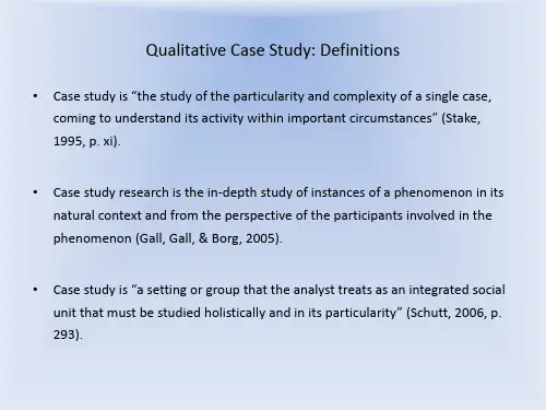

基于mssqlserver的银行信贷管理系统的设计与实现计算机应用专业研究生:指导老师:【摘要】随着银行业信息化的不断发展,银行信贷业务的管理系统建设,实现信贷业务进行管理信息化成为了当前发展趋势。
课题在技术框架下,利用了SQL Server数据库技术,研究了针对信贷业务的管理系统。
目前,所实现的银行信贷系统中,主要表现出操作不够便利、数据访问效率低等缺点,逐渐地无法适应当前银行业发展的需求。
课题分析、设计、实现、测试了基于B/S模式的信贷管理系统,提供给银行如:信贷过程管理、信贷客户管理、信用评级管理、贷后管理等操作功能。
本文的信贷管理系统将在三层架构下运行,具有数据传输效率高、维护方便等特点,主要研究内容如下。
首先,作者对银行信贷系统进行需求分析,先根据银行信贷系统的建设目标,设计了系统的用例图、系统数据流图,包括了:顶层数据、安全数据、查询数据等流程,同时,论文分析了银行信贷系统的运行性能和业务性能;其次,作者对银行信贷系统的总体架构进行设计,分析设计了系统的功能模块、功能流程、应用层次、网络拓扑结构,其次根据需求分析,具体地设计了系统的业务功能;同时,利用UML建模设计序列图和状态图的,设计了系统数据库,分别就数据库表字段信息、E-R关系图进行设计。
最后,分别就设计与实现银行信贷系统的模块有:信用评级管理模块、系统用户登录模块、信贷流程管理模块、授信额度管理模块、信贷客户信息管理模块、贷后信息管理模块、系统数据管理模块等,分别就模块的操作界面、功能操作代码、以及数据处理流程,进行了详细地设计与实现。
本课题设计与实现的银行信贷管理系统,在浏览器下运行和操作,相对于C/S模式下的系统来说,提高了系统的可操作性、便利性,更加方便了系统的数据维护。
系统的测试显示,通过系统的测试与分析,如数据添加、查询、删除等操作功能运行稳定,得出系统的测试结果,其性能与功能指标,页面响应时间均保持在200毫秒范围内,信贷管理系统的功能与运行性能,均满足业务需求,也符合通信类系统的特性需求。
Mission Reliability Modeling for Equipment System Based on the Operational Viewpoint ofDoDAF 2.0Lin Shaoyang,College of Information System and Management National University of Defense TechnologyChangsha, P. R. China***************************Wu XiaoyueCollege of Information System and Management National University of Defense TechnologyChangsha, P. R. ChinaAbstract—Currently, Department of Defense Architecture Framework (DoDAF) 2.0 is widely used in many aspects of the architecture-related modeling fields. Due to the highly complex structure of architecture, its reliability became a pivotal issue. However, DoDAF 2.0 is lack of a specific viewpoint to model the reliability of the architecture. This paper introduces an approach to deal with reliability modeling method related missions posed by Equipment System (ES), which is an obvious characterized architecture. OV-1, OV-5a and OV-6c of DoDAF 2.0's operational viewpoint are extracted and extended as the modeling framework. Use case diagram, class diagram and sequence diagram of Unified Modeling Language (UML) are picked to present the products mentioned. The study also regulates a series of standards for each extended product in detail, in order to collect requisite reliability-related parameters for further analysis and calculation. Later, the proposed model is applied to an ES as an example to verify its availability.Keywords-reliability modeling; equipment system; mission reliability; equipment system; operational viewpoint; DoDAF2.0I.I NTRODUCTIONEquipment System (ES) is made up of wide ranges of correlative and function-complementary equipment, which integrate into an organic integrity of diverse categories, structures and scales, according to the claim of optimal placement and operational capability, thus making up a large high-level system, namely System of Systems (SoS) or architecture.Reliability is a key performance parameter in system design, so has become a basis factor affecting mission success [1]. Mission is the foundation of ES, since all member of ES are related with each other as a whole by the same target—achieving the specific destination. Mission reliability refers to the probability that a system will perform its specified mission in its mission section [2]. Therein, mission section is the profile to the events and time sequence the mission has to follow. Mission reliability reflects the ability of fulfilling the task successfully, thus playing a big part in ES operational effectiveness.On the basis of multi-view method, Architecture Framework (AF) provides a collection of normalized modeling process and description method, which standardizes the contents contained to ensure the unified understanding and comparing principal from all stakeholders [3]. Currently DoDAF 2.0 of U.S. is often adopted as descriptive model in military field [4-6]. Nonetheless, no specialized reliability modeling viewpoint or product arises in DoDAF 2.0.Several reliability modeling methods have been used in the mission reliability analysis. Fault tree analysis is suitable in describing non-repairable systems in [7–9], but its limitations become apparent when conducted to quantitative issues. Bayesian Networks were developed as a logic graphical representation [10–11], and it has shown its agile computation efficiency. This approach is also applied in the proposed methodology. Later, state-space models, namely Markov chains and Petri nets, appear as main methods for analyzing system's dynamic reliability [12-14]. However, it has the state space growth explosion problem.Yet, methods mentioned above show weakness on describing ES, since ES usually has great amount of units of different levels and complicated logical relations. On the other hand, product sets of DoDAF 2.0 do not supply all sufficient data for ES reliability analysis. In the paper, we propose a reliability modeling framework based on the operational viewpoint of DoDAF 2.0, viewing to probe into a reliability modeling framework to ES.For the rest of the paper, section II introduces DoDAF 2.0 and its operational viewpoint. Section III demonstrates the processed reliability modeling product set and its UML description in detail. Section IV describes the application of this approach to an ES as a case study. Section V summarizes the paper and gives a perspective to further research.II.D O DAF2.0A ND I TS O PERATIONAL V IEWPOINTDoDAF 2.0 is a graphical and tabular description for SoS. It provides general guidance for development, usage and management of DoD architectures with an emphasis on interoperability and integration between constituentInternational Conference on Logistics Engineering, Management and Computer Science (LEMCS 2014)systems in SoS [15]. In total, 8 viewpoints and 52 products are built in DoDAF 2.0.Viewpoint replaces "view" of antecedent versions, in order to coordinate with ISO. These viewpoints are further classified for describing the overarching aspects for every viewpoint (All Viewpoint, AV), requirements and deployments (Capability Viewpoint, CV), data relationships and alignment structure (Data and Information Viewpoint, DIV), operation scenarios and activities (Operational Viewpoint, OV), relationships between OV&CV and projects being implemented (Project Viewpoint, PV), performers, activities services and their exchanges (Service Viewpoint, SvcV), applicable principals (Standard Viewpoint, StdV), and the composition, interconnectivity and context (System Viewpoint, SV),as Fig.1 demonstrating. Each of these views has a well-defined product set in accordance with different perspectives.The DoDAF 2.0 viewpoints reside in a presentation layer, underlying which there is a data layer where defining attributes and relationships of the architecture can be documented [16]. There is a natural and straight correspondence between AF and UML [3]. Additionally, DoDAF 2.0 formalism is increasingly being supported by other commercially available architecting tools, in which documents, sheets, matrices and such structured presentations are employed to narrow development cycle, e.g. DOORs of Telelogic, Requisite Pro of Rational and Caliber RM of Borland. One of the advantages UML possesses is that not only does it allow capturing DoDAF 2.0's data layer but also supports modeling and simulation on purpose of verification.OV describes the missions and activities, operational elements, and resource flow exchanges required to conduct operations [16]. OV is adept at tracing system's dynamic behaviors and transformation, and just such character makes it quiet suitable for modeling ES mission reliability. OV has 9 products in total, involved capturing organization relationships, resource flows, state transition and other architecture's characters. For mission reliability modeling, this paper provides a tailored product set, including OV-1, OV-5a and OV-6c to model ES's mission reliability, and it would be elaborately discussed in nextFigure 1. DoDAF 2.0 eight viewpoints.III.M ISSION R ELIABILITY M ODEL U NDER OVProduct SetThe clipped product set of ES mission reliability model is shown in Fig. 1.OV-1 aims at describing the contents and processes of the mission(s) that ES has to fulfill. Graph of jpg is recommended as the storage format. Its visualized representation enables further reliability modeling, meanwhile offering information particularly concerned by high-level decision makers during their decision process. OV-1's contents depend on the unique objective and application of specific ES. In general, it may involve operation processes, organization hierarchy, geographical distribution and operational expectations including what missions will emerge, which unit(s) will undertake, what sequences should be complied with et al, and also the interaction with external environment and systems. The links between two elements are suggested but not limited as one of the follows:∙Control: Control link from A to B means B's activity is managed by A's instructions.∙TrackInfo: TrackInfo link represents the information flow movements.∙Assistance: Assistance link from A to B indicates that if B gets failed, A would make up.∙Affirm: Affrim link reports the lower equipment's being- state and attack-complete state from lowerlevel to the command center.The relationships of the elements on the diagram sometimes convey their relative position, although this is not specifically captured in the semantics. Since each ES differs, we do not set specific rules for OV-1.OV-5a is a newly created product in DoDAF 2.0, in order to describe mission constituents and their hierarchical structure. Through the decomposition it can be cleared that the duty each mission should accomplish and unnecessary redundancy that can be eliminated. Thus the model could be simplified and efficiency may be improved as well. To clarify the affect that lower-level failure brought about to higher missions, logic connections are introduced into OV-5a. Currently 'AND' gate and 'OR' gate are mainly considered. They can be defined as follows.Def. 1AND gate: Only when all nodes under AND gate succeed does mission above the gate succeed, as Fig. 2(a).Def. 2OR gate: As long as at least one of the nodes under OR gate succeeds will mission above the gate succeed, as Fig. 2(b).OV-6c depicts the sequence and information exchanges between phases. Through constant refining to the mission process, execution order and rules would be gradually precise and accurate. UML sequence diagram is adopted as representation standard. Sequence division is consistent with divided layered graph of OV-5a. On top of the graph is ES' object, accompanied by its relevant lifeline. Specific time points are labeled on left of the lifeline labels. Bars on the lifeline stand for its duration time. Solid arrow line is message transiting between objects.In each phase's sequence diagram, time propels in terms of lifeline. In reality, lifeline is finite and does not fit for long-time phase. Thus object's lifeline should be regulated in more details. As Fig. 3 shows, on left of the object A's lifeline, t11represents A's start time and similarly t12 end time, while t21 is the time message 1 from another object arrives. t22 on the right indicates message 2 leaving time.A N DP 1P 2AO RP 1P 2BFigure 2. (a) AND gate example. (b) OR gate examplemessage 2O bj ect A t 11t12t 22message 1t 21Figure 3. OV-5a UML sequence diagram representationIV. UML D EFINITIONa. OV-5a UML normalizationOV-5a describes the operations that are normally conducted in the different nodes. The extended use-case and class diagram provides a means of breaking down activities to lower level activities as well as indicating the nodes that perform the activities. It includes node, activity, link and logic relation. Their normalized data definition is shown in table 2 (a)-(d).b. OV-5a UML normalizationThe OV-6c is used to define time based behavioral scenarios between operational elements. The interactions can be service operations as well as the interactions defined on OV-5a diagrams. There are three types of elements in OV-6c: node, lifeline and message transit. Therein, node data definition is the same as OV-5a. Lifeline can be potentially described by the messageArrivingTime and messageLeavingTime attributes of message transit. Table 3 illustrates the data definition for message transit.TABLE I.ES M ISSION R ELIABILITY M ODELTABLE II.(A)D ATA D EFINITION F OR N ODETABLE III. (A) D ATA D EFINITION M ESSAGE TRANSITV.C ASE S TUDYAn ES is presented in this part as a detailed illustration to the proposed model. The system basically consists of five parts: Ground Based Interceptor (GBI), X band Ground Based Rader (GBR), Battle Management and Command, Control & Communications (BM/C3) system, Upgraded Early Warning Radar (UEWR), and Defense Support Program/Space-Based Infrared System (DSP/SBIRS) [17].GBI is an up-to-date kinetic energy antipersonnel weapon intercepting ballistic missile warheads in its midcourse outside the atmosphere and destroying it through straightly impact. Traditional GBI consists of Exoatmospheric Kill Vehicle (EKV) and two booster rockets.GBR is X band phased array radar, and it is the main fire control radar of the system, deployed at the same place with GBI. It mainly involves surveillance, capture, trace, identification, fire control assistance and damage evaluation.BM/C3 is the brain of system, connecting all constituent systems organically. It mainly involves in receiving data from each detector to analyze the striking missile's parameters (like speed, trajectory, point of fall et. al), calculating "sweet point", directing UEWR and GBR to trace and capture the target, giving launch orders to GBI, offering revised target information to the flying interceptor, evaluation intercepting effect, and so on. BM/C3 is also deployed with GBI and GBR.UWER is upgraded phased array radar used to detect and track ballistic missile and provide early warnings. It detects and traces ballistic missile initial flight and provides GBR rough azimuth information.DSP supplies early warnings for the system. Via merging data from two or more DSPs, ballistic trajectory can be forecasted. Furthermore, compared with foregone missiles' infrared characteristics, the ballistic version can be confirmed. Currently, DSP is gradually replaced by SBIRS, which consists of two kinds satellites: Lower Earth Orbit (LEO) and High Earth Orbit (HEO). Highly flexible infrared sensor technique of HEO conveys strategy, the launch and flight of theatre ballistic missile, global theatre infrared data and processed intelligence. LEO satellites are equipped with two kind sensors: the capture one is to observe flame during the rocket launch phase; the other trace one could keep in track with the locked target from its midcourse until back into the atmosphere.Fig. 4 is the OV-1 model of the system. Substantially the system functions in such procedures:1: Early warning phase1) DSP/SBIRS detects the booster's plume when the striking ballistic missiles launches, and traces until its booster rocker turning off. Via repeater satellite or earth station, DSP/SBIRS sends trackinfo back to BM/C3for predicting the striking missile's incoming direction as well as impact area. Pertinent data would also be sent to UEWR.2) After gets information of ballistic position, UEWR will search and detect associative airspace to trace the striking missile. When discovering missile warhead, it will track robustly and send trackinfo to BM/C3.2: Interception decision phase1) BM/C3formulates operations management plan, including intercepting pattern, interceptor quantity, calculating effective acting distance, thus preliminarily ascertaining GBI's launch direction and moment. Meanwhile BM/C3should send control information to GBI and receive affirm to get its authorization.2) BM/C3 sends trackinfo got from UEWR to GBR to guide its search. Through detecting and tracing ballistic warhead, GBR would retrieve more precise information for BM/C3decision. Meanwhile, GBR would generate warhead image by sufficient data it has collected.3) BM/C3conducts target identification and threat evaluation to verify the warhead version, the trajectory and the impact point. On this basis, interception decision about GBI's launch moment and estimated interception point is made. When the accuracy of the estimated interception point is within the appointed scope (20km), BM/C3 would give GBI launching orders targeting on the estimated interception point.3:Interception implementation phase1) As soon as receiving orders, GBI launches immediately. After that, GBR precisely tracks GBI and warhead, returns revised objective data back to BM/C3 to update GBI's flight.2) When GBI reaches the estimated airspace, EKV separates with the booster rocket. Then EKV compares the target information detected with former images provided by GBR to verify and target objective, thus destroying it through straight collision.4: Interception effectiveness evaluation1) During the GBI collision, GBR collects interception data sending back to BM/C3.2) BM/C3evaluated the interception effectiveness. If failed, BM/C3 has to decide whether to conduct a second interception.According to the procedure, its operational activities decomposition can be depicted like Fig. 5(a). Furthermore, Fig. 5(b) shows the class diagram for the case "EKV attack". On purpose of saving space, some of the class attribute values and operations have been omitted. For the proposed model of OV-6c, the above mentioned interception decision phase is hired as an example, and it is shown in Fig. 6.VI.C ONCLUSIONDoDAF 2.0 is a rife model framework for ES. The paper proposes a mission reliability modeling method based on the operational viewpoint of DoDAF 2.0 and illustrates the UML normalization. An ES is an example of highly complex and adaptive ES characterized by a loosely coupled federation of constituent systems. The proposed model succeeds in describing ES reliability structure, proving the methods validity. For further research, transition mechanism between OV-5a and OV-5b can be investigated in terms of enriching the product set and heterogeneous representation. Besides, UML entities can be enlarged for more abundant and convenient details. More importantly, system view's product can also be used on mission reliability modeling.A CKNOWLEDGMENTThe paper is partly supported by National Natural Science Foundation of China under grant no. 71071159.Figure 4.OV-1 modelD S P /S B I R Sdet ect pl um et racem i ssi l est ore dat asend i nf o.recei ve com m andU E W Rsearchw arheadG B IG B Rl aunch gi ve orders<extends><extends>revi se fli ghtseparat eboost ersE K V at t ack<extends><extends><extends>recei vei nf o.cal cul at edeci degenerat ei m ageFigure 5. (a) OV-5a modelactivityIDnodeContained activityDescription successrulesE K VA t t acknodeId ofActivity linkIn linkToprerequisitesuccessProbability startTime endTimeE K V S eparat enodeId ofActivity linkIn linkToprerequisitesuccessProbability startTime endTimeA t t ackO rdermessageType messageIdmessageFrom: GBR, UEWR messageArrivingTime Fl i ght P osi t i onE K V posi t i oni ngmessageType messageIdmessageFrom: GBR messageArrivingTimeR evi sed Fl i ght ANDmessageType messageId messageFrom messageTomessageArrivingTime messageLeavingTimeTarget V eri ficat i on ANDFigure 5. (b) OV-5a class diagram for the case "EKV attack"U E W RG B RB M /C 31: controlAuthorizationG B I6: launch decision order(position,time)3: traceMessage5: traceMessagewarhead image4: traceMessage 2: af f i r m at i onFigure 6. OV-6c Sequence diagram for interception decision phaseR EFERENCES[1] Reliability primer for command, control, communications,computer, intelligence, surveillance, and reconnaisssance (C4ISR) facilities. available at: http: // www. usace. ary. mil /publications/ armytm/tm5-698-3/entire.pdf.2005a.[2] Chul Kim, “Analysis for mission reliability of a combat tank ,”IEEE Transactions on Reliability, vol. 38, no. 2, pp 242-245, 1989. [3] Robert K. Garrett, Steve A., Neil T Baron, “Managing theinterstitials, a system of systems framework suited for the ballistic missile defense system ,” Systems Engineering, vol 14,no. 1, pp. 87-108,2011.[4] Yang Kewei and Tan Yuejin, Architecture RequirementsTechnique and Method. Peking: Science Press, 2010.[5] Shu Yu, Research on weapon equipment architecture modelingmethod and application based on the capability requirements, Ph.D. Dissertation, National University of Defense Technology, 2009. [6] Jiang Zhiping, Research on architecture verification method andkey technique for C4ISR system based on CADM, Ph.D. Dissertation, National University of Defense Technology, 2007. [7] Bobbio A., Portinale L, “Improving the analysis of dependablesystems by mapping fault trees into Bayesian networks ,” Reliability Engineering & System Safety, vol. 71, no. 5, pp 249-260, 2001.[8] Hichem Boudali, Joanne,Bechta Dugan, “Dynamic fault treemodels for fault tolerant computer systems ,” IEEE Transaction On Reliability, vol. 41, no. 3, pp 363-377, 1992.[9] Huang Chin-Yu, Chang Yung-Ruei, “An improved decompositionscheme for assessing the reliability of embedded systems by using dynamic fault trees,” Reliability Engineering & System Safety, vol 92, no. 10, pp 1403-1412, 2007.[10] Boudali H., Dugan J. B, “A discrete-time Bayesian networkreliability modeling and analysis framework ,” Reliability Engineering & System Safety, vol 87, no. 6, pp 337-349, 2005. [11] Hichem Boudali, Joanne Bechta Dugan, “A continuous-timeBayesian network reliability modeling and analysis framework ,” IEEE Transaction On Reliability, vol 55, no. 1, pp 34-41, 2006. [12] Jau-Yeu Menq, Pan-Chio Tuan, “Discrete Markov ballistic missiledefense system modeling ,” European Journal of Operational Research, vol 178, no. 1, pp 560-578, 2007.[13] Kim K, Park S, “Phased-mission system reliability under Markovenvironment ,” IEEE Transaction On Reliability, vol 43, no. 5, pp 301-309, 1994.[14] Abidin E.Olmez, “Mission centric reliability analysis of C4ISRarchitectures using petri net ,” In Proceedings of IEEE International Conference on Systems, Man and Cybernetics, pp 587-592, 2003. [15] Department of Defense Architecture Working Group, DoDArchitecture Framework 2.0, Volume 2: Architecture and Models, available at: /Portals/0/Documents/DODAF/DoDAF_v2-02_web.pdf[16] Biswas, A, Hayden, J, Phillips, MS, Bhasin, KB, Putt, C, &Sartwell, T, “Applying DoDAF to NASA orion mission communication and navigation architecture. In Proceedings of IEEE Aerospace Conference, pp 1-9, 2008.[17] Wang Minle and Li Yong, Ballistic Missile PenetrationEffectiveness Analysis. Peking: National Defense Industry Press, 2010.。
Taking the classroom to the stage is an innovative approach to education that combines the traditional learning environment with the dynamic atmosphere of a performance.This method can greatly enhance the learning experience for students by engaging them in a more interactive and immersive way.Here are some key points to consider when writing an essay on this topic:1.Introduction to the Concept:Begin by explaining the idea of bringing the classroom to the stage.Discuss how this approach differs from traditional classroom settings and why it is gaining popularity.2.Benefits of StageBased Learning:Elaborate on the advantages of this method.These may include:Engagement:Students are more likely to be engaged when they are part of a performance.Memory Retention:The act of performing can help students remember information more effectively.Creativity:Stagebased learning encourages students to think creatively and solve problems in new ways.Collaboration:Working together on a performance can foster teamwork and communication skills.3.Types of StageBased Learning:Describe different forms this method can take,such as: DramaBased Education:Using drama to explore and understand academic subjects. RolePlaying:Assigning roles to students to simulate reallife scenarios or historical events.Interactive Lectures:Incorporating elements of performance into lectures to make them more dynamic.4.Case Studies or Examples:Provide examples of schools or educational institutions that have successfully implemented stagebased learning.Discuss the outcomes and how it has impacted the students.5.Challenges and Solutions:Address potential challenges,such as the need for specialized training for teachers,the cost of staging performances,and the time required for preparation.Offer solutions to these challenges,like professional development workshops or partnerships with local theaters.6.Technological Integration:Discuss how technology can enhance stagebased learning, such as using multimedia presentations,interactive whiteboards,or virtual reality to create immersive learning experiences.7.Conclusion:Summarize the main points of your essay and emphasize the importance of innovative educational methods like stagebased learning.Encourage further exploration and implementation of such methods in educational settings.8.Personal Reflection:If appropriate,include a personal reflection on how you believe stagebased learning could benefit you as a student or how you have seen it positively impact others.9.Call to Action:End your essay with a call to action,encouraging educators, administrators,and students to consider the benefits of integrating stagebased learning into their curriculum.10.References:If you have cited any sources or studies,be sure to include a list of references at the end of your essay.Remember to use clear and concise language,and to structure your essay in a logical and coherent manner.This will help your reader to understand and appreciate the value of taking the classroom to the stage.。
Automated Formal Verification ofModel TranformationsD´a niel Varr´o and Andr´a s PatariczaBudapest University of Technology and EconomicsDepartment of Measurement and Information SystemsH-1521Budapest,Magyar tud´o sok k¨o r´u tja2.varro,pataric@mit.bme.huAbstract.As the Model Driven Architecture(MDA)relies on complex andhighly automated model transformations between arbitrary modeling languages,the quality of such transformations is of immense importance as it can easily be-come a bottleneck of a model-driven design process.Automation surely increasesthe quality of such transformations as errors manually implanted into transforma-tion programs during implementation are eliminated;however,conceptualflawsin transformation design still remain undetected.In this paper,we present a meta-level and highly automated technique to formally verify by model checking that amodel transformation from an arbitrary well-formed model instance of the sourcemodeling language into its target equivalent preserves(language specific)dy-namic consistency properties.We demonstrate the feasibility of our approach ona complex mathematical model transformation from UML statecharts to Petrinets.Keywords:model transformation,graph transformation,model checking,formalverification,MDA,UML statecharts,Petri nets.1IntroductionNowadays,the Model Driven Architecture(MDA)of the Object Management Group (OMG)has become the dominating trend in software engineering.The core technology of MDA is the Unified Modeling Language(UML),which provides a standard way to buildfirst a platform independent model(PIM)of the target system under design, which may be refined afterwards into several platform specific models(PSMs).Finally, the target application code should be generated automatically by off-the-shelf UML CASE tools directly from PSMs.While MDA puts the stress on a precise object-oriented modeling language(i.e., UML)as the core technology,it fails to sufficiently emphasize the importance of precise and highly automated model transformations for designing and implementing mappings from PIMs to PSMs,or PSMs to application code.The methodology(if there is any) behind existing code generators integrated into off-the-shelf UML CASE tools relieson textual programming language translations,which does not scale up for the needs of a UML based visual modeling environment.Moreover,PIM-to-PSM mappings are frequently hard wired into the UML tool thus it is almost impossible to be tailored to special requirements of applications.In case of dependable and safety critical applications,further model transforma-tions are necessitated to map UML models into various mathematical domains(like Petri nets,dataflow networks,transition systems,process algebras,etc.)to(i)define formal semantics for UML in a denotational way[2,7,8,16],and/or(ii)carry out for-mal analysis of UML designs[4,13].In the current paper,we investigate the model transformation problem from a gen-eral perspective,i.e.,to specify how to transform a well-formed instance of a source modeling language(which is typically UML in the context of MDA)into its equivalent in the target modeling language(which can be UML,a target programming language, or a mathematical modeling language).Related work in model transformations Model transformation methodologies have been under extensive research recently.Existing model transformation approaches can be grouped into two main categories:–Relational approaches:these approaches typically declare a relationship between objects(and links)of the source and target language.Such a specification typically based upon a metamodel with OCL constraints[1,11,17].–Operational approaches these techniques describe the process of a model transfor-mation from the source to the target language.Such a specification mainly com-bines metamodeling with(c)graph transformation[5,8,9,14,27],(d)triple graph grammars[22](e)term rewriting rules[28],or(f)XSL transformations[6,19].Many of the previous approaches already tackle the problem of automating model transformations in order to provide a higher quality of transformation programs com-pared with manually written ad hoc transformation scripts.Problem statement However,automation alone cannot protect against conceptualflaws implanted into the specification of a complicated model transformation.Consequently, a mathematical analysis carried out on the UML design after an automatic model trans-formation might yield false results,and these errors will directly appear in the target application code.As a summary,it is crucial to realize that model transformations themselves can also be erroneous and thus becoming a quality bottleneck of MDA.Therefore,prior to analyzing the UML model of a target application,we have to prove that the model transformation itself is free of conceptual errors.Correctness criteria of model transformations Unfortunately,due to their wide range of applications in the MDA environment,it is hard to establish a single notion of correct-ness for model transformations.The most elementary requirements of a model transfor-mation are syntactic.–The minimal requirement is to assure syntactic correctness,i.e.,to guarantee that the generated model is a syntactically well–formed instance of the target language.2–An additional requirement(called syntactic completeness)is to completely cover the source language by transformation rules,i.e.,to prove that there exists a corre-sponding element in the target model for each construct in the source language.However,in order to assure a higher quality of model transformations,at least the following semantic requirements should also be addressed.–Termination:Thefirst thing we must also guarantee is that a model transformation will terminate.This is a very general,and modeling language independent semantic criterion for model transformations.–Uniqueness(Confluence,functionality):As non-determinism is frequently used in the specification of model transformations(as in the case of graph transformation based approaches)we must also guarantee that the transformation yields a unique result.Again,this is a language independent criterion.–Semantic correctness(Dynamic consistency):In theory,a straightforward cor-rectness criterion would require to prove the semantic equivalence of source and tar-get models.However,as model transformations may also define a projection from the source language to the target language(with deliberate loss of information), semantic equivalence between models cannot always be proved.Instead we define correctness properties(which are typically transformation specific)that should be preserved by the transformation.Unfortunately,related work addressing these correctness criteria of model transfor-mations is very limited.Syntactic correctness and completeness was attacked in[27] by planner algorithms,and in[10]by graph transformation.Recently in[15],sufficient conditions were set up that guarantee the termination and uniqueness of transformations based upon the static analysis technique of critical pair analysis[12].However,no approaches exist to reason about the semantic correctness of model transformations.To be precise,the CSP based approach of[9]that aims to ensure dy-namic consistency of UML models has the potential to be extended to reason about properties of transformations.However,defining manually the semantics of an arbitrary modeling language by mapping it into CSP is much more difficult and less intuitive than defining the operational semantics of the language by graph transformation.Our contribution In this paper,we present a meta-level and highly automated frame-work(in Sec.2)to formally verify by model checking that a model transformation from an arbitrary well-formed model instance of the source modeling language(specified by metamodeling and graph transformation techniques)into its target equivalent preserves (language specific)dynamic consistency properties.We demonstrate the feasibility of our approach(in Sec.3)on verifying a semantic property of a complex model transfor-mation from UML statecharts to Petri nets.2Automated Formal Verification of Model TransformationsWe present an automated technique to formally verify(based on the model checking approach of[24])the correctness of the model transformation of a specific source model into its target equivalent with respect to semantic properties.32.1Conceptual overviewA conceptual overview of our approach is given in Fig.1for a model transformation from anfictitious modeling language A(which will be UML statecharts for our demon-strating example later on)to B(Petri nets as in our case).Modeling language A Modeling language BFig.1.Model level formal verification of transformations1.Specification of modeling languages.As a prerequisite for the framework,eachmodeling language(both A and B)should be defined precisely using metamodeling and graph transformation techniques(see,for instance,[26]for further details). 2.Specification of model transformations.Moreover,the A2B model transforma-tion should be specified by a set of(non-conflicting)graph transformation rules.3.Automated model generation.For any specific(but arbitrary)well-formed modelinstance of the source language A,we derive the corresponding target model by automatically generated transformation programs(e.g.,generated by VIATRA[5] as tool support).4.Generating transition systems.As the underlying semantic domain,a behav-iorally equivalent transition system is generated automatically for both the source and the target model on the basis of the transformation algorithm presented in[24] (and with a tool support reported in[21]).5.Select a semantic correctness property.We select(one or more)semantic prop-erty p in the source language A which is structurally expressible as a graphical pattern composed of the elements of the source metamodel(and potentially,some temporal logic operators).Note that the formalization of these criteria for a specific model transformation is not at all straightforward.In many cases,we can reduce the question to a reach-ability problem or a safety property,but even in this casefinding the appropriate4temporal logic formulae is non-trivial.More details on using graphical patterns to capture static well-formedness properties can be found,e.g.,in[10].6.Model check the source model.Transition system A is model-checked automati-cally(by existing model checker tools like SAL[3]or SPIN)to prove property p.This model checking process should succeed,otherwise(i)there are inconsisten-cies in the source model itself(a verification problem occurred),(ii)our informal requirements are not captured properly by property p(a validation problem oc-curred),or(iii)the formal semantics of the source language is inappropriate as a counter example is found which should hold according to our informal expectations (another validation problem).7.Transform and validate the property.We transform the property p into a propertyq in the target language(manually,or using the same transformation program).As a potentially erroneous model transformation might transform incorrectly the property p in to property q,domain experts should validate that property q is really the target equivalent of property p or a strengthened variant.8.Model check the target model.Finally,transition system B is model-checkedagainst property q.–If the verification succeeds,then we conclude that the model transformation is correct with respect to the pair(p,q)of properties for the specific pairs of source and target models having semantics defined by a set of graph transformation rules.–Otherwise,property p is not preserved by the model transformation and de-bugging can be initiated based upon the error trace(s)retrieved by the model checker.As before,this debugging phase mayfix problems in the model trans-formation or in the specification of the target language.Note that at Step2,we only require to use graph transformation rules to specify model transformations in order to use the automatic program generation facilities of VIATRA.Our verification technique is,in fact,independent of the model transforma-tion approach(only requires to use metamodeling and graph transformation for speci-fying modeling languages),therefore it is simultaneously applicable to relational model transformation approaches as well.Prior to presenting the verification case study of a model transformation,we briefly discuss the pros and contras of metamodel level and model level verification of model transformations.2.2Metamodel vs.model level verification of model transformationsIn theory,it would be advisable to prove that a model transformation preserves certain semantic properties for any well-formed model instance,but this typically requires the use of sophisticated theorem proving techniques and tools with a huge verification cost. The reason for that relies in the fact that proving properties even in a highly automated theorem prover require a high-level of user guidance since the invariants derived directly from metamodels should be typically manually strengthened in order to construct the proof.In this sense,the effort(cost and time)related to the verification of a transforma-tion would exceed the efforts of design and implementation which is acceptable only for very specific(safety-critical)applications.5However,the overall aim of model transformations is to provide a precise and au-tomated framework for transforming concrete applications(i.e.,UML models).There-fore,in practice,it is sufficient to prove the correctness of a model transformation for any specific but arbitrary source model.Thanks to existing model checker tools and the transformation presented in[24],the entire verification process can be highly auto-mated.In fact,the selection of a pair(p,q)of corresponding semantic properties is the only part in our framework that requires user interaction and expertise.Even if the a verification of a specific model transformation is practically infea-sible due to state space explosion caused by the complexity of the target application, model checkers can act as highly automated debugging aids for model transformations supposing that relatively simply source benchmark models are available as test sets.As a conclusion,from an industrial perspective,a highly automated debugging aid for model transformations(as provided by our model checking based approach)is(at least)as valuable as a user guided excessive formal verification of a transformation.3Case Study:From UML Statecharts to Petri NetsWe present(an extract of)a complex model transformation case study from UML stat-echarts to Petri nets(denoted as SC2PN)in order to demonstrate the feasibility of our verification technique for model transformations.The SC2PN transformation was origi-nally design and implemented as part of an industrial project where UML statecharts are projected into Petri nets in order to carry out various kinds of formal analysis(e.g.,func-tional correctness[18],performance analysis[13])on UML designs(i.e.,to formally analyze UML models but not model transformations).Due to severe page limitations, we can only provide an overview of the verification case study,the reader is referred to[25]for a more detailed discussion.3.1Defining modeling languages by model transformation systemsPrior to reasoning about this model transformation,both the source and target model-ing languages(UML statecharts and Petri nets)have to be defined precisely.For that purpose,in[26]we proposed to use a combination of metamodeling and graph trans-formation techniques:the static structure of language is described by a corresponding metamodel clearly separating static and dynamic concepts of the language,while the dynamic operational semantics is specified by graph transformation.Graph transformation(see[20]for theoretical foundations)provides a rule-based manipulation of graphs,which is conceptually similar to the well-known Chomsky grammar rules but using graph patterns instead of textual ones.Formally,a graph transformation rule(see e.g.addT okenR in Fig.3for demonstration)is a triple,where is the left-hand side graph,is the right-hand side graph,while is(an optional)negative application condition(grey areas infigures).Informally,and of a rule defines the precondition while de-fines the postcondition for a rule application.The application of a rule to a model(graph)(e.g.,a UML model of the user) alters the model by replacing the pattern defined by with the pattern of the. This is performed by61.finding a match of the pattern in model;2.checking the negative application conditions which prohibits the presence ofcertain model elements;3.removing a part of the model that can be mapped to the pattern but not thepattern yielding an intermediate model;4.adding new elements to the intermediate model which exist in the butcannot be mapped to the yielding the derived model.In our framework,graph transformation rules serve as elementary operations while the entire operational semantics of a language or a model transformation is defined by a model transformation system[27],where the allowed transformation sequences are constrained by controlflow graph(CFG)applying a transformation rule in a specific rule application mode at each node.A rule can be executed(i)parallelly for all matches as in case forall mode;(ii)on a(non-deterministically selected)single matching as in case of try mode;or(iii)as long as applicable(in loop mode).UML statecharts as the source modeling language As the formalization of UML statecharts(abbreviated as SC)by using this technique and a model checking case study were discussed in[23,24],we only concentrate on the precise handling of the target language(i.e.,Petri nets)in this paper.We only introduce below a simple UML model as running example and assume the reader’s familiarity with UML and metamodels. Example1(Voting).The simple UML design of Fig.2)models a voting process which requires a consensus(i.e.,unique decision)from the participants.Fig.2.UML model of a voter systemIn the system,a specific task is carried out by multiple calculation units CalcUnit, and they send their local decision to the Voter in the form of a yes or no message.The voter may only accept the result of the calculation if all processing units voted for yes. After thefinal decision of the voter,all calculation units are notified by an accept or a decline message.In the concrete system,two calculation units are working on the7desired task(see the object diagram in the upper right corner of Fig.2),therefore the statechart of the voter is rather simplified in contrast to a parameterized case.Petri nets as the target modeling language Petri nets(abbreviated as PN)are widely used means to formally capture the dynamic semantics of concurrent systems due to their easy-to-understand visual notation and the wide range of available tools.A precise metamodeling treatment of Petri nets was discussed in[26].Now we briefly revisit the metamodel and the operational semantics of Petri nets in Fig.3.enableTransR delTokenRFig.3.Operational semantics of Petri nets by graph transformation According to the metamodel(the Petri Net package in the upper left corner of Fig.3),a simple Petri net consists of Place s,Transition s,InArc s,and OutArc s as depicted by the corresponding classes.InArcs are leading from(incoming)places to transitions,and OutArcs are leading from transitions to(outgoing)places as shown by the associations.Additionally,each place contains an arbitrary(non-negative)num-ber of token s).Dynamic concepts,which can be manipulated by rules(i.e.,attributes token,andfire)are printed in red.The operational behavior of Petri net models are captured by the notion offiring a transition which is performed as follows.1.First,fire attributes are set to false for each transition of the net by applying ruledelFireR in forall mode.82.A single enabled transition T(i.e.,when all the places P with an incoming arc A tothe transition contain at least one token token0)is selected to befired(by setting thefire attribute to true)when applying rule enableTransR in try mode.3.Whenfiring a transition,a token is removed(i.e.,the counter token is decremented)from each incoming place by applying delTokenR in forall mode.4.Then a token is added to each outgoing place of thefiring transition(by increment-ing the counter token)in a forall application of rule addTokenR.5.When no transitions are enabled,the net is dead.3.2Defining the SC2PN model transformationModeling statecharts by Petri nets Each SC state is modeled with a respective place in the target PN model.A token in such a place denotes that the corresponding state is active,therefore,a single token is allowed on each level of the state hierarchy(forming token ring,or more formally,a place invariant).In addition,places are generated to model messages stored in event queues of a statemachine.However,the proper handling of event queues is out of the scope of the current paper,the reader is referred to[25].Each SC step(i.e.,a collection of SC transitions that can befired in parallel)is projected into a PN transition.When such a transition isfired,(i)tokens are removed from source places(i.e.,places generated for the source states of the step)and event queue places,and(ii)new tokens are generated for all the target places and receiver message queues.Therefore,input and output arcs of the transition should be generated in correspondence with this rule.Example2.In Fig.4,we present a(n extract)of the Petri net equivalent of the voter’s UML model(see Fig.2).For improving legibility,only a single transition(leading from state may forfor accept,decline)and message queues for validevents(like yes).The initial state ismarked by a token in wait vote.The depicted transition has two in-coming arcs as well,one from its sourcestate mayforautomatically,which would yield the target Petri net model(Fig.4)as the output when supplying(the XMI representation of)the voter’s UML model(Fig.2)as the input.Figure5gives a brief extract of transforming SC states into PN places.According to this pair of rules,each initial state(i.e.,that is active initially)in the source SC model is transformed into a corresponding PN place containing a single token,while each non-initial state(i.e.,that is passive initially)is projected into a PN place without a token.active2placeRpassive2placeR Fig.5.Transforming SC states into PN placesIt is worth noted that a model transformation rule in VIATRA is composed of ele-ments of the source language(like State S in the rule),elements of the target language (like Place P),and reference elements(such as RefState R).Latter ones are also defined by a corresponding metamodel.Moreover,they provide bi-directional transformations for the static parts of the models,thus serving as a primary basis for back-annotating the results of a Petri net based analysis into the original UML design.3.3Verification of the SC2PN model transformationFor the SC2PN case study,Steps1–3in our verification framework have already been completed.Now,a transition system(TS)is generated automatically(according to[24]) for source and target models as an equivalent(model-level)representation of the oper-ational semantics defined by graph transformation rules(on the meta-level). Generating transition systems Transition systems(or state transition systems)are a common mathematical formalism that serves as the input specification of various model checker tools.They have certain commonalities with structured programming languages(like C or Pascal)as the system is evolving from a given initial state by executing non-deterministic if-then-else like transitions(or guarded commands)that manipulate state variables.In all practical cases,we must restrict the state variables to havefinite domains,since model checkers typically traverse the entire state space of the system to decide whether a certain property is satisfied.For the current paper,we use the easy-to-read SAL[3]syntax for the concrete representation of transition systems.Our generation technique(described in[24]also including feasibility studies from a verification point of view)enables model checking for graph transformation systems by automatically translating them into transitions systems.The main challenge in such a translation is two fold:(i)we have to“step down”automatically from the meta-level to10the model-level when generating model-level transition systems from meta-level graph transformation systems,and(ii)a naive encoding of the graph representation of models would easily explode both the state space and the number of transitions in the tran-sition system even for simple models.Therefore our technique applies the following sophisticated optimizations:–Introducing state variables in TS only for dynamic concepts of a language.–Including only dynamic parts of the initial model in the initial state of the TS.–Collecting potential applications of a graph transformation rule by partially apply-ing them on the static parts of the rule and generating a distinct transition(guarded command)for each of them that only contains dynamic parts as conditions in guards and assignments in actions.In order to give an impression on the generated target transition system,we give below an extract from the SAL encoding of our Petri net model(of Fig.4).%Type declarationsplaceID:TYPE=wait_for_vote,may_accept,decline,v_yes,c1_accept,c1_accept;transID:TYPE=t,...;pn1:MODULE=BEGIN%declaring state variablesGLOBAL token:ARRAY placeID OF INTEGERGLOBAL fire:ARRAY transID OF BOOLEANINITIALIZATIONtoken[wait_for_vote]=1;token[decline]=0;token[may_accept]=0;token[v_yes]=0;...fire[t]=FALSE;...TRANSITION%generated for one potential matching of rule enableTransR fire[t]=FALSE ANDNOT(token[wait_for_vote]=0)ANDNOT(token[v_yes]=0)-->fire’[t]=TRUE;[]...END;–The objects and variable domains are transformed into type(domain)declarations (see,e.g.,the corresponding value for place decline in type placeID).–State variable arrays are introduced only for attributes token andfire(the only dynamic concepts of Petri nets).–Initialization is consistent with the initial marking of the Petri net(i.e.,place wait vote contains a token thus the corresponding variable token is initialized to1).–The guarded command generated from the potential application of rule enable-TransR to the PN transition depicted Fig.4only checks the corresponding dynamic concepts(thefire attribute is false and there are tokens in both places wait vote and vFormalizing the correctness property Now,a semantic criterion is defined for the verification process that should be preserved by the SC2PN model transformation.Note that the term “safety criterion”below refers to a class of temporal logic properties pro-hibiting the occurrence of an undesired situation (and not to the safety of the source UML design).Definition 1(Safety criterion for statecharts).For all OR-states (non-concurrent composite states)in a UML statechart,only a single substate is allowed to be active at any time during execution.This informal requirement can be formalized by the following graphical invariant in the domain of UML statecharts (cf.Fig.6together with its equivalent logic formula).Informally speaking,it prohibits the simultaneous activeness of two distinct substates S1and S2of the same OR state C (i.e.,non-concurrent composite state).Unfortunately,it is difficult to estab-Fig.6.A sample graphical safety criterion lish the same criterion on the meta level in the target language of Petri nets since the SC2PN transformation defines an ab-straction in the sense that message queuesof objects are also transformed into PNplaces (in addition to states).However,in order to model check a certain sys-tem,this meta-level correctness criterion can be re-introduced on the model level.Therefore,we first automatically instan-tiate (the static parts of)the criterion on the concrete SC model (as done during the transformation to transitions systems)to obtain the model level criterion of Fig.7.Note that the different (model level)patterns denote conjunctions,therefore,none of the de-picted situations are allowed tooccur.Fig.7.Model level safety criterionEquivalent property in the target language This model level criterion is appropri-ate to be transformed into an equivalent criterion for the Petri net model.As the state12。
(完整)软件工程专业英语编辑整理:尊敬的读者朋友们:这里是精品文档编辑中心,本文档内容是由我和我的同事精心编辑整理后发布的,发布之前我们对文中内容进行仔细校对,但是难免会有疏漏的地方,但是任然希望((完整)软件工程专业英语)的内容能够给您的工作和学习带来便利。
同时也真诚的希望收到您的建议和反馈,这将是我们进步的源泉,前进的动力。
本文可编辑可修改,如果觉得对您有帮助请收藏以便随时查阅,最后祝您生活愉快业绩进步,以下为(完整)软件工程专业英语的全部内容。
软件工程英语文档:Documents 软件工具:Software Tools 工具箱:Tool Box 集成工具:Integrated Tool 软件工程环境:Software Engineering Environment 传统:Conventional 经典:Classical 解空间:Solution Domain 问题空间:Problem Domain 清晰第一,效率第二Clarity the first,Efficiency the next。
设计先于编码Design before coding使程序的结构适合于问题的结构Make the program fit the problem开发伴随复用,开发为了复用Development with reuse, Development for reuse。
靠度量来管理:Management by Measurement软件度量学:Software Metrics 软件经济学:Software Economics 软件计划WHY软件分析WHAT软件实现HOW 软件生存周期过程的开发标准Standard for Developing Software Life Cycle Process 软件开发模型:Software Development Model 编码员:Coder 瀑布模型:Waterfall Model 快速原型模型:Rapid Prototype Model增量模型:Incremental Model 线性思维:Linear Thinking 演化模型:Evolutionary Model 螺旋模型:Spiral Model 对象:Object 类:Class 继承:Inheritance 聚集:Aggregation 消息:Message 面向对象=对象Object+分类Classification+继承Inheritance+消息通信Communication with Messages 构件集成模型:Component Integration Model 转换模型:Transformational Model净室软件工程:Cleanroom Software Engineering 净室模型:Cleanroom Model 软件需求规格说明书:Software Requirement Specification ,SRS 分析模型:Analysis Model 便利的应用规约技术:Facilitated Application Specification Techniques ,FAST结构化语言:Structured Language 判定树:Decision Tree 基数:Cardinality 事件轨迹:Event Trace 对象-关系Object-Relationsship 结构化分析:SA(Structured Analysis)由顶向下,逐步细化Top-Down Stepwise Refinement 面向对象分析:Object—Oriented Analysis包含:Contains 临近:Is Next To 传到:Transmits to 来自:Acquires from 管理:Manages 控制:Controls 组成:Is Composed of 细化:Refinement 抽象:Abstraction 模块:Module 策略:Strategy 信息隐藏:Information Hiding 数据封装:Data Encapsulation 抽象数据类型:Abstract Data type模块化设计:Modular Design 分解:Decomposition 模块性:Modularity 单模块软件:Monolithic Software 模块独立性:Module Independence内聚:Cohesion 偶然性内聚:Coincidental Cohesion逻辑性内聚:Logical Cohesion 时间性内聚:Temporal Cohesion 过程性内聚: Procedural Cohesion通信性内聚: Communicational Cohesion顺序性内聚:Sequential Cohesion功能性内聚:Functional Cohesion非直接偶合:No Direct Coupling 数据偶合:Data Coupling 特征偶合:Stamp Coupling 控制偶合:Control Coupling 外部偶合:External Coupling 公共偶合:Common Coupling 内容偶合:Content Coupling 由底向上设计:Bottom—Up Design 自顶向下设计:Top—Down Design 正式复审:Formal Review 非正式复审:Informal Review 走查,排练:Walk—Through 会审:Inspection 映射:Mapping 传入路径:Afferent path 传出路径:Efferent path 变换中心:Transform Center 接受路径:Reception path 动作路径:Action path 事务中心:Transaction Center 分支分解:Factoring of Brandches瓮形:oval-shaped 一个模块的控制域:Scope of Control一个模块的作用域:Scope of Effect结构化程序设计:Structured Programming通心面程序:Bowl of Spaghetti 流程图:Flow Diagram 编码:Coding方框图:Block Diagram PDL (Pidgin):Program Design Language伪代码:Pseudo Code JSD:Jackson System Development 对象建模技术:Object Modeling Technique基础设施:Infrastructure 控制线程:Thread of Control 保护者对象:Guardian Object 协议:protocol UML:Unified Modeling Language OMG:Object Management Group 统一方法:Unified Method 关联:Association 泛化:Generalization 依赖:Dependency 结点:Node 接口:Interface 包:Package 注释: Note 特化:Specialization 元元模型:Meta-Meta Model 用户模型:User Model 静态图:Static Diagram 动态图:Dynamic Diagram 用例视图:Use Case View 逻辑视图:Logical View 并发视图:Concurrent View 构件视图:Component View 实现模型视图:Implementation Model View 部署视图:Deployment View 航向:Navigability 重数:Multiplicity 共享聚集:Shared Aggregation 组合:Composition 泛化:Generalization 简单消息:Simple Message 同步消息:Synchronous Message 异步消息:Asynchronous Message 事件说明:Event_Signature 守卫条件:Guard_Condition 动作表达式:Action_Expression 发送子句:Send_Clause 时序图:Sequence Diagram 协作图:Collaboration Diagram 前缀:Predecessor 循环子句:Iteration-Clause 活动图:Activity Diagram 构件图:Component Diagram 配置图:Deployment Diagram 建模过程指导(RUP):Rational Unified Process 可执行代码:Executalbe Codes 实现:Implementation 编码风格:Coding Style 标准:Classical 控制流的直线性:Linearity of Control Flow 程序风格设计要素:先求正确后求快Make it right before you make it faster. 先求清楚后求快Make it clear before you make it faster. 求快不忘保持程序正确Keep it right when you make it faster。
compliant clinical study. It is almost impossible to achieve the ideal proclaimed in the existing guidelines and regulations. However, this does not mean we should not strive for the best standard possible. You must think beyond the 'minimum standard' if you really want to do a good job and ensure the best quality possible. Slavish adherence to guidelines and regulations will not work: you must be convinced of the basic logic, ethics and science behind GCP requirements. Going for the most expedient and cheapest route will not only result in a poorer standard but it may also cost lives.首先,我们应该清楚,在我们看来,没有完全依从GCP的临床研究,完美遵从目前指导原则和法规几乎是不可能的。
但是,这并不意味着我们就不应该尽可能达到最好的标准。
如果你确实想要做好工作并尽可能确保高质量,就必须考虑超过最低标准。
机械的遵从指导原则和法规是没有用的,但必须遵循GCP要求的基本的逻辑、伦理和科学原则。
一味的寻求最方便、最便宜的途径将不仅仅导致一个更低的标准,也可能增加成本。
How much non-compliance should we tolerate? In 1996, we published a book on GCP compliance based on the findings of our audit experience at 226 investigator study sites, involving studies conducted in 20 different countries, and audited by an independent external audit team between 1991 and 1995. GCP compliance was compared for various factors and the data patterns suggested some interesting trends. First, the overall level of GCP compliance was generally poor across all investigator study sites and far below the expectations of guidelines and regulations. (In many areas, the studies were possibly dangerous for study subjects, in our opinion.) Second, there were no important differences in studies with regard to the year in which the study was conducted. Basically, all the new regulatory efforts, particularly in Europe, did not show a positive effect onstandards. (However, a survey over a five- to six-year time period is possibly too limited to draw conclusions on this point.) Third, there were no important differences in studies which used a CRO (contract research organization) compared to those which did not. This appears to be because CROs simply follow the standards of the sponsor responsible for the conduct of the study rather than setting consistent and better standards themselves. Fourth, some slight differences between phases of studies were observed, with better compliance in early phase studies. However, this should not be surprising since a Phase I single-centre study with 20 subjects is much easier to control than a Phase III multicentre multinational study involving several hundred study subjects. Fifth, there were some slight differences between therapeutic areas, but this was probably linked to the standards of the sponsor or CRO managing the studies. Sixth, overall, there were no basic overall differences between levels of GCPcompliance in different countries. (However, a later analysis of selected items showed some individual differences between countries: for example, direct access to source documents was achieved 100% of the time at US sites, but not as frequently in other countries.)The only apparent important differences in levels of GCP compliance were between the different sponsors (mostly pharmaceutical companies) managing the studies. The main conclusions reached from analysis of this audit database were that overall standards of GCP compliance greatly needed improvement, and that standards were only as good as the sponsor managing the study regardless of where in the world the study was being conducted. In theory, good research could be conducted anywhere provided it was managed properly.我们可容许多大的非依从性呢?1996年我们出版了一本关于GCP依从性的书,此书根据我们在226个研究基地的稽查发现编写,涉及了1991年到1995年间20个不同国家并由独立的外部稽查小组稽查的研究。
联锁系统UML模型的建立与形式化验证刘征;武晓春【摘要】针对目前计算机联锁系统建模与验证难度较大的问题,提出一种UML(Unified Modeling Language)与NuSMV(New Symbolic Model Verifier)相结合的计算机联锁模型形式化检验方法.以一个标准站场中的一条接车进路建立过程为例,对联锁系统需求进行分析并通过UML建立相应的模型,再列出它与NuSMV之间的映射关系并实现将UML模型自动转换为NuSMV形式化模型,最后完成对计算机联锁系统的验证,检测其需求中可能存在的漏洞.该方法能够降低对计算机联锁系统形式化建模与验证的难度与减少人工建模时可能出现的错误,为计算机联锁系统形式化模型的建立与验证提供一种新思路.%Aiming at the difficulties in the modeling and verification of the computer interlocking system,a formal model verification method of computer interlocking based on UML and NuSMV is proposed.Firstly taking a route setting process of a standard station as an example,this paper analyzes the requirements of the computer interlocking system and establishes the corresponding model with UML.Then the mapping relationship between UML and NuSMV is listed,and the conversion from UML model to NuSMV formal model is completed automatically.Finally,the formal model is verified to find possible vulnerabilities of the computer interlock system.This method can not only reduce the difficulties in formal modeling and verification of the system,but also avoid artificial modeling errors,thus providing a new way for the formal modeling and verification of the computer interlocking system.【期刊名称】《铁道标准设计》【年(卷),期】2018(062)006【总页数】7页(P164-170)【关键词】形式化验证;计算机联锁系统;UML;NuSMV;模型转换【作者】刘征;武晓春【作者单位】兰州交通大学自动化与电气工程学院,兰州730070;兰州交通大学自动化与电气工程学院,兰州730070【正文语种】中文【中图分类】TP301.2;U284.36随着软件技术的不断发展,人们对于软件的正确性与安全性的要求也在不断提高,在许多领域中提出需使用安全苛求系统作为安全的保障[1]。
A Case Study in Verification of UML Statecharts:the PROFIsafe ProtocolR.MalikDepartment of Computer Science,University of WaikatoHamilton,New Zealandrobi@R.M¨u hlfeldSiemens Corporate Technology,CT SE 5Postfach 3220,91050Erlangen,Germanyreinhard.muehlfeld@Abstract:We discuss our experience obtained during the PROFIsafe verification and test case generation project at Siemens Corporate Technology.In this project,a for-mal analysis of the PROFIsafe protocol for failsafe communication has been carried out.A formal model based on finite-state machines has been obtained from the UML specification of the protocol.This model has been analysed with formal verification techniques,and several important properties have been proven.Based on the verified model,a set of test cases for the automatic execution of conformance tests has been derived.The paper explains how the UML statecharts defining the PROFIsafe proto-col are translated into finite-state machines,and points out important aspects and problems occurring during the modelling and verification of industrial applications.Key Words:Reliability,Verification.Categories:C.2.2[Computer-Communication Networks]:Network Protocols—proto-col verification;D.2.2[Software Engineering]:Design Tools and Techniques—state dia-grams;D.2.4[Software Engineering]:Software/Program Verification—model checking.1IntroductionIn this paper,we discuss the verification and test case generation of the industrial field bus protocol PROFIsafe [10].This protocol has been analysed in a project at Siemens Corporate Technology,using the VALID Toolset as a model checking environment.A preliminary report on the project has been presented in [8].The PROFIsafe protocol,which is used for failsafe communication in indus-trial field bus systems,must provide a very high level of reliability.Therefore,several measures are taken in order to ensure the correctness of the protocol specification.The formal analysis using model checking is one of these mea-sures.As another measure,a certified testing environment is being set up in order to ascertain that implementations of the protocol conform to the verified specification.The behaviour of the PROFIsafe protocol is specified by means of UML state-charts.Its verification therefore leads to the general problem of verifying UMLJournal of Universal Computer Science, vol. 9, no. 2 (2003), 138-151submitted: 14/10/02, accepted: 14/2/03, appeared: 28/2/03 J.UCSstatecharts,which has been addressed by several other researchers [6,7,12].For example,[6,12]describe a translation of general UML statecharts into PROMELA for verification by the SPIN model checker [5].In contrast,the speci-fications to be verified in our project use only a small subset of UML statecharts.This does not only enable us to use a simpler translation procedure;it also avoids several ambiguities encountered when dealing with general UML statecharts.This paper is organised as follows.In Section 2,we introduce the PROFIsafe specification and the statecharts used.Afterwards,in Section 3,we discuss the abstraction steps needed in order to obtain a formal model of the protocol.In Section 4,we describe the translation process used to transform the UML statecharts into the finite-state machines used by the model checker.In Section 5,we explain which properties of the protocol were verified and present some of the results.In Section 6,we show how test cases were generated from the verified protocol.Finally,Section 7contains some concluding remarks.2The PROFIsafe ProtocolThe PROFIsafe protocol [10]is used for failsafe communication between two agents using an insecure communication medium.The aim of failsafe commu-nication is to ensure that two communication partners always enter a defined safe state in the event of any communication failure.This is important in many technical systems for which a high level of safety is required.Although originally defined as an extension of the PROFIBUS field bus proto-col [4],the PROFIsafe protocol can be used to establish failsafe communication based on any underlying communication medium.Independently of the commu-nication medium,it is designed to ensure a maximum error rate of one unnoticed fault in 109hours of operation [10].The protocol defines communication between two distinguished communica-tion partners,called host and slave ,who exchange messages via the underlying communication medium,called grey channel (Figure 1).The host usually runs on a controlling computer,while the slave typically runs on a technical device which is controlled by the host.Two kinds of slaves are considered:an input slave represents a field device collecting data,e.g.a sensor,whereas an output slave merely consumes data received from the host.The protocol specification makes no assumptions about the grey channel,which may produce all kinds of communication failures,such as delay,modifica-tion,duplication,or loss of messages.However,in most practical applications,such errors are assumed to occur only sparsely.The objective of PROFIsafe is to detect these sparse failures,should they occur,and to switch host and slave to their defined safe states before the fault can cause any harm.The PROFIsafe profile [10]defines a new layer of failsafe communication by specifying two new components called F-host and F-slave .The ‘F’in F-host139Malik R., Muehlfeld R.: A Case Study in Verification of UML Statecharts ...140Malik R., Muehlfeld R.: A Case Study in Verification of UML Statecharts ...Figure1:PROFIsafe architecture.and F-slave is used throughout the PROFIsafe profile to identify the‘failsafe’components introduced.These components use the grey channel as an underlying communication medium,and provide a means of failsafe communication to their users,represented by the application processes of the host and slave(Figure1).The basic idea of the protocol consists of sending acknowledgements and monitoring live signs in the form of consecutive numbers in combination with timers.To this end,the PROFIsafe profile defines the following additional infor-mation to be put into all messages sent via the insecure grey channel. Consecutive number.Each message is equipped with a consecutive number, which is used by the recipient for monitoring the life of the sender and the communication link.Both communication partners continuously check whether the other partner manages to update the consecutive number beforea defined watchdog time has elapsed.Eight bits are reserved for the consecutive number.The value0is used only for thefirst protocol cycle.Afterwards,the consecutive number runs in cyclic mode from1...255,wrapping over back to1at the end.CRC2checksum.Each message is equipped with an additional CRC check-sum.This checksum is used to detect spurious or corrupted messages,which may have slipped unnoticed through the grey channel.Status byte.Each message sent from the F-slave to the F-host contains an additional status byte,with individual bits reserved for the different possible faults.In this way,the F-slave informs the F-host that it has detected a certain error,e.g.a CRC fault.Figure 2:The statechart defining the behaviour of the PROFIsafe F-host.The PROFIsafe profile [10]describes the behaviour of the PROFIsafe F-host and F-slave by means of UML statecharts.As an example,Figure 2shows the statechart defining the behaviour of the PROFIsafe F-host.The statecharts used here are very simple,exploiting only few features of the rich statecharts language provided by UML [9].For example,there is no state hierarchy,and there are no entry,exit,or internal actions associated to states.In this way,the model remains very clear and avoids the ambiguities related to advanced features of UML statecharts [6,12].Also,the developers of this specification can be very sure that it will be interpreted in the same way by different readers and UML tools.Activity states ,in which a communication partner is waiting for new messages to arrive,are highlighted in the PROFIsafe state diagrams (Figure 2).In this way,the synchronisation constraints are made explicit.3Creating a Formal ModelIn order to verify the protocol specification,a rigorous formal model needs to be extracted from the statecharts.Most of the transitions in the statecharts (Figure 2)contain verbal descriptions,which still require interpretation by a 141Malik R., Muehlfeld R.: A Case Study in Verification of UML Statecharts ...142Malik R., Muehlfeld R.: A Case Study in Verification of UML Statecharts ...human.Therefore,thefirst step involves adding the formal details which are missing in the semi-formal guards and actions labelling the transitions.We also need to abstract from some of the data used by the protocol,and we need to introduce a simple description of the behaviour of the grey channel. These tasks are not only needed in order to cope with the complexity of the model,but also to obtain a meaningful verification model at all.We use the following data abstractions.–The verification model abstracts away from all user data.It deals only with the logic behaviour of the two communication partners;it cannot be checked whether any data values are transferred correctly.–The CRC2checksum,which in the real model is an integer of16or32bits, is not modelled explicitly.Instead,it is replaced by a single bit,containing only the information whether a message contains a correct or an incorrect checksum.This completely suffices to analyse the logic behaviour of the protocol,but of course makes it impossible to analyse the correctness of the CRC computation algorithm.–The verification model assumes a maximum consecutive number of3or4, thus considering only a small part of the original range from0to255.This simplification is justified as follows.Afinite range of consecutive num-bers causes problems when the wrap-over from the maximum value back to1occurs too quickly,so that a message from the next cycle of consecu-tive numbers is wrongly taken for a duplicate.Obviously,this problem is more likely to occur if the range of possible consecutive numbers is reduced.Therefore,if we can verify that a model with only4different consecutive numbers does not have any problem,we can conclude that the same model with256different consecutive numbers also behaves correctly.In order to perform formal verification,it also is essential to formalise the behaviour of the environment in which the system to be verified runs,i.e.the grey channel.The behaviour of the grey channel is described verbally in the PROFIsafe profile[10].For verification purposes,we need a formal model of the underlying communication medium which includes the possibility of the communication faults to be considered.We use a grey channel of limited buffering capacity which can delete,modify, and duplicate messages,and produce spurious messages.However,if a message is modified or a spurious message is produced,we assume the CRC2checksum of the delivered message to be incorrect.This reflects the assumption that corrupted messages occur randomly,and are not introduced maliciously.Since PROFIsafe is only required to protect a system from technical faults,this is a reasonable assumption.In any verification task,it is essential to identify and formalise such additional assumptions.Without the above assumption,it would be impossible to prove any useful property of the PROFIsafe protocol.Most verification tasks of industrial applications require similar kinds of ab-straction and additional modelling.Unfortunately,carrying out this abstraction is a difficult task which cannot be performed automatically.The authors be-lieve that this is one of the major obstacles preventing formal verification from becoming commonly used in industry.4From UML Statecharts to Finite-State MachinesWe use the model checker of the VALID Toolset to verify the PROFIsafe proto-col.The VALID Toolset,developed at Siemens Corporate Technology,supports the modelling,verification and code generation of finite-state machines as de-scribed in [1,2,11,13].Accordingly,the formalised and abstracted statecharts specifying the PROFIsafe protocol are translated into appropriate finite-state machines.The framework used by the VALID Toolset is that of discrete-event systems (DES)[11,13].In this context,a finite-state machine is defined to be a 5-tupleG =(Σ,Q,δ,q 0,Q m ),where Σis an alphabet of events ,Q is the state set (assumed finite and non-empty),δ:Q ×Σ→Q is the transition function ,q 0∈Q is the initial state ,and Q m ⊆Q is the set of marked or terminal states.The transition function δ:Q ×Σ→Q is defined at each state q ∈Q only for some of the events σ∈Σ,i.e.δis a partial function.Such finite-state machines can be represented graphically as a state transition graph (e.g.in Figure 3).States are represented as nodes,with the initial state highlighted by a thick border,and marked states coloured grey.The transition function δis represented by directed edges between states:the graph contains an edge labelled σfrom a state q 1to state q 2whenever δ(q 1,σ)=q 2.Multiple finite-state machines can be composed by synchronisation on com-mon events.All synchronised state machines repeatedly agree on an event to be executed next,and simultaneously perform the corresponding state transition.A state transition using an event σcan only take place,if all synchronised state machines which have σin their event alphabet allow the event σto occur,i.e.if the transition function δis defined for the event σat the current state.For more details on synchronous composition and other concepts from the theory of discrete-event systems,please refer to [2,11,13].The framework of finite-state machines used here can be considered as a very restricted subset of UML statecharts.There are no variables,guards,or assignments;only simple events can be used for synchronisation.143Malik R., Muehlfeld R.: A Case Study in Verification of UML Statecharts ...t 48t 9331111s6await check wait delay prepare ack Figure 3:Finite-state machine derived from PROFIsafe F-host statechart.In order to obtain a set of finite-state machines from the UML statecharts constituting the PROFIsafe specification,we perform a two-step translation.In the first step,we create one finite-state machine from each statechart,by deleting all guards and actions from the transitions and replacing them by event labels.For example,the statechart in Figure 2is replaced by a finite-state machine as shown in Figure 3.This step apparently removes all data dependencies from the transitions.The synchronisation constraints described by the guards and actions on the transitions are introduced into the model by adding one state machine for each variable used in the statechart.As an example,consider the variable representing the CRC2checksum of the last message received by the F-host.After data abstraction,this variable is modelled as a flag,called in CRC ,which is set if the last message had a correct CRC2checksum.This variable is represented by a finite-state machine with three states as shown in Figure 4.There are two states ok and nok representing the situation that the flag in CRC is on or off,plus an additional state init representing a flag with initially undefined value.The flag in CRC can change its value when a mes-144Malik R., Muehlfeld R.: A Case Study in Verification of UML Statecharts ...t 108t 48t 78t 105t 45t 75rcv.*.*.*.*.okFigure 4:Finite-state machine for in CRC variable of PROFIsafe F-host.sage with correct or incorrect CRC2checksum is received (events rcv.*.*.*.*.ok resp.rcv.*.*.*.*.nok ).In addition,the current value of the flag restricts the possible transitions of the main statechart.Consider the transition from state 4to state 5of the F-host statechart (Figure 2).This transition can only be taken if the last message received had no faults,i.e.if in CRC is set.Accordingly,the transition event t 45in the finite-state machine of Figure 3must be disabled if in CRC is not set.This constraint is enforced by adding a selfloop labelled with this event to state ok in Figure 4.By constructing such finite-state machines for the statecharts of the F-host and the F-slave and their variables,we obtain a behavioural model of the PROFI-safe protocol.Given that the original UML statecharts are specified using formal notation,the translation into finite-state machines can be performed automati-cally.This translation process so far has only been carried out for the PROFIsafe model,but based on the experience obtained,it can easily be extended to handle arbitrary statecharts.In addition,we need to model the behaviour of the grey channel.Since no UML description of the grey channel is available,the grey channel has been modelled directly as finite-state machines.Different models have been created,representing different fault possibilities and buffering capacities.For the F-host,F-slave,and grey channel together,we obtain models consisting of 300to 383finite-state machines,depending on the grey channel and protocol configuration considered.5VerificationBased on the finite-state machine model of the PROFIsafe protocol,two steps of verification have been carried out.Firstly,we have performed some standard checks of universal properties in order to find out whether the logic specified by the statecharts is consistent,or whether it contains any undesirable loops 145Malik R., Muehlfeld R.: A Case Study in Verification of UML Statecharts ...146Malik R., Muehlfeld R.: A Case Study in Verification of UML Statecharts ...or deadlocks.Secondly,we have checked whether the protocol satisfies certain application-specific properties regarding failsafe communication.5.1Universal PropertiesUniversal properties are defined in a general way for a class offinite-state ma-chines,usually specifying some kind of consistency which developers would like to have satisfied for any system they develop.Their advantage is that they can be checked directly for any system,as a push-button technology,without the user having to provide any additional input.We have checked the PROFIsafe model for the following universal properties.Controllability.A specification is called controllable[11,13]if it can always cope with any external events which it may receive as input.In the case of a PROFIsafe component(F-host or F-slave),this means that the component must always be able to handle any possible incoming messages as well as any external events such as timeouts.Termination.We have analysed the PROFIsafe specification in order to check whether it permits infinite control-loops[3],i.e.whether it is possible that the execution enters an infinite loop without ever reaching an activity state.This is an important question,since such a control-loop would permit the state machine to get stuck in an infinite execution without ever considering new input events.Confluence.Next,we have checked that the behaviour defined by the PROFI-safe statecharts is confluent[3].This means that the protocol defines a deter-ministic behaviour,i.e.that there are no situations in which the specification permits multiple responses,e.g.the sending of different messages,after the same sequence of inputs.Although not essential,such determinism usually is desired by developers.Furthermore,creating test-cases as discussed in Sec-tion6is much easier based on a confluent model,since there is only one possible response at each state.Nonconflicting.Finally,we have checked whether the PROFIsafe specification is nonconflicting[11,13].A model is considered to be nonconflicting if,in every situation,it is always possible to reach a given terminal state.This is a crucial property for any useful specification:if it is not satisfied,this means that the system may run into a livelock or into a deadlock.In our analysis of the PROFIsafe specifications,we have included terminal states by defining a situation of normal operation,which should be reachable from any other state:a communication partner is in a terminal state if itis waiting for new messages during normal operation,all message buffers contain good messages,and no errors are present.In contrast to the properties discussed above,the nonconflicting property may cease to hold if the behaviour of the environment is restricted.Non-conflicting only means that the specification can reach a terminal state in cooperation with the environment.If the environment is not cooperative,for example if it does never send a certain message required to reach the ter-minal state,then a deadlock situation may occur although the specification has been proven to be nonblocking.Therefore,we have performed the non-conflicting check based on different assumptions about the messages which can be received from the grey channel.The PROFIsafe model has been successfully verified to satisfy each of the universal properties listed above.5.2Application-Specific PropertiesAs a second step of verification,we have defined and checked several application-specific properties of the PROFIsafe protocol.Most importantly,we have ex-amined whether the requirements of failsafe communication are guaranteed.We have checked whether the occurrence of a fault causes both communication part-ners to switch to their failsafe states within the required delay time.There are different classes of faults to be considered,such as the occurrence of a corrupted message (CRC fault)or the loss of a message (timeout).For each kind of fault,it is required that,after recognition of the fault,both communication partners switch to their failsafe states.Therefore,for each fault,we have verified separately that the agent recognising the fault and its partner switch to their failsafe states within a certain time limit.As is to be expected,verifying this property for the partner of the agent recognising the fault turns out to be more difficult,since both agents and an appropriate model of the grey channel need to be considered during verification.All the required properties were formally described by additional finite-state machines and verified by VALID using a language inclusion check as described in [1].This analysis produced a couple of counter-examples,which pointed to some problems in an earlier version of PROFIsafe,and which were used to im-prove the next version of the profile [10].5.3Experimental ResultsThe table in Figure 5shows some of the experimental data collected during verification,namely the performance of the nonconflicting checks performed on 147Malik R., Muehlfeld R.: A Case Study in Verification of UML Statecharts ...Consecutive Slave Timing Grey Peak Peak CPUnumbers config.model channel states transitions time0..3input no store11,67235,31887.48soutput40,657349,560168.73sinput store21,67235,31871.41sinput keepseq15,12135,31873.11soutput226,3231,748,860151.16sinput keepseq221,944257,123143.00s0..4input yes timed146,946315,008227.25soutput266,3382,034,385355.68s Figure5:Experimental data from PROFIsafe nonconflicting checks.the PROFIsafe model.As a nonconflicting check always requires the entire model to be taken into account,this is one of the more difficult verification tasks.As explained above and can be seen in the table,the conflict check was carried out on different versions of the PROFIsafe model,considering input and output slave configurations with different ranges of consecutive numbers,and using different grey channel models.The grey channels store1,store2,keepseq1,and keepseq2are simple grey chan-nels withfixed buffering capacity and the ability to modify messages provided that the CRC2checksum of the modified message is incorrect.Channels store1 and store2can also modify a message by just changing its consecutive number and leaving the CRC2checksum intact;this is used to model a PROFIsafe config-uration in which the consecutive number is not included in the CRC2checksum. Channels store1and keepseq1have a buffering capacity of1,i.e.there can be at most one undelivered message at any time.In contrast,channels store2and keepseq2have a buffering capacity of2.Furthermore,we have created and analysed a PROFIsafe model including timing assumptions,which is needed to verify certain application-specific prop-erties requiring timing constraints.This model has been combined with a grey channel model called timed1with buffering capacity of1,the ability to modify messages provided that the CRC2checksum of the modified message is incorrect, and some assumptions limiting the amount of time how long a message can be kept within the channel.The table in Figure5shows some performance data collected when using the VALID Toolset for checking the different PROFIsafe models to be nonconflicting. For each run,the table shows the maximum number of states and transitions constructed by the algorithm:this gives a rough estimate of the amount of memory required.Furthermore,the amount of CPU time consumed for eachverification run is given.All runs were carried out on a600MHz Pentium III processor with512MB of RAM.In summary,we can say that the verification of the complete protocol can be carried out within some minutes on a standard personnel computer.However, it was not possible to verify the model after further increasing its complexity. Thus,the models described here must be considered as the most complex models that can presently be handled by the tool.6Automated TestingBased on the verified model,we have computed test cases which can be used to execute conformance tests,in order to ascertain that a protocol implementation has the same behaviour as the verified model.These test cases will be made available to vendors of PROFIBUS applications,who will then be able to obtain certificates of conformance for their implementations more easily.In order to generate test cases from a model automatically,we mustfirst spec-ify a coverage criterion.A coverage criterion defines a set of states or transitions which must at least be visited when executing the generated test suite.Which coverage criterion is most useful,depends on the specific application.The usual approach when testing an implementation is to try covering all possible portions of the implementation’s code.When testing a PROFIsafe component,this cor-responds to executing all transitions of the component’s statechart.Yet,such an approach relies on the specific implementation suggested by the statecharts given in the PROFIsafe profile,and does not consider alternative implementa-tions,which may use completely different states and transitions.Therefore,we have considered alternative criteria,which rely on the possible exchange of messages defined by the protocol instead of its statechart represen-tation.For generating our test cases,we have required that,during the execution of the test suite,the component under test should at least once send and receive all possible sequences of two messages,which may occur according to the proto-col specification.In this way,we expect to cover the relevant behaviour,since the PROFIsafe standard defines whether a message is to be considered as cor-rect based on the previous message received.Therefore it is sufficient to consider sequences of two messages.Like verification,test case generation is performed on a simplified PROFI-safe model with a limited range of consecutive numbers(0..4instead of0..255). Using the full range of consecutive numbers would require more than106pairs of messages to be considered in each test suite.Such a test suite,besides being impractically large,would include many instances of the same logical behaviour, only with different consecutive numbers.By using the restricted range of con-secutive numbers,we obtain test cases which still cover all the relevant logicalbehaviour and are much better usable.In order to actually run the tests,the consecutive numbers from the computed test cases are mapped to the full range in an appropriate way.The task of test case generation has been carried out for the PROFIsafe F-slave model.Two test suites have been computed,for an F-slave in input and output slave configuration,respectively.Each test suite contains six test cases, with the largest test case consisting of2253events.These test cases are currently used to implement a certified testing environment for F-slave implementations. In a second step,it is planned to do the same for the PROFIsafe F-host.7ConclusionsWe have discussed the verification and test case generation for the industrialfield bus protocol PROFIsafe.The protocol is specified using a restricted version of UML statecharts,which is free from ambiguities.After applying some abstrac-tions,the statecharts are translated intofinite-state machines and analysed using the VALID Toolset.In order to perform the formal analysis,the protocol specification given as UML statecharts has to be translated into a formal model consisting offinite-state machines.During the project described here,a specialised translation pro-cess was used,which has been implemented only for the PROFIsafe model.Yet, the translation process can be fully automated and applied to other statecharts as well.In the future,we would like to extend it to a more general tool,which can also handle the more complex constructs in general UML statecharts.In the PROFIsafe specification,very simple statecharts are used,which,while exploiting only few features of UML statecharts,have the very clear and unam-biguous semantics needed for formal analysis.Based on this restricted state-charts language,it is possible to obtain expressive verification results,which have helped the designers to improve their specification.Furthermore,it is pos-sible to generate test suites with guaranteed coverage,which will be used for automated conformance tests of PROFIsafe implementations. AcknowledgementsThe authors would like to thank Bertil Brandin for his support and helpful comments in preparing this paper.References1. B.A.Brandin,R.Malik,and P.Dietrich.Incremental system verification andsynthesis of minimally restrictive behaviours.In American Control Conference, 2000.。