Cisco组网实例
- 格式:doc
- 大小:36.00 KB
- 文档页数:4
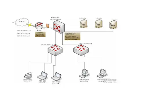
案例描述典型中小企业组网实例,申请一个公网IP和10M带宽,一台CISCO路由器,WEB服务器,文件服务器,FTP服务器等,客户端办公电脑,300台左右,多部门划分VLAN,用ACL控制各部门访问权限,配置网络打印机。
解决方案1,配置Routera).配置接口Interface fastethernet0/1Ip address 172.27.0.1 255.255.255.252Duplex autoSpeed autoIp nat insideNo shutdownInterface fastethernet0/2Ip address 202.103.0.117 255.255.255.248Duplex autoSpeed autoIp nat outsideNo shutdownb)配置路由ip route 0.0.0.0 0.0.0.0 202.103.0.117c).配置过载ip nat inside source list 110 interface FastEthernet0/2 overloadaccess-list 110 permit ip 172.27.0.0 0.0.255.255 anyd).配置端口映射Ip nat inside source static tcp 172.27.2.1 80 202.103.0.117 80 映射WEB服务器Ip nat inside source static tcp 172.27.2.2 21 202.102.0.117 21 映射FTP 服务器文件服务器 172.27.2.3 只提供企业内网使用,不配置端口映射2,配置Core switch CISCO 4503a)配置VTPVTP Version : 2Configuration Revision : 7Maximum VLANs supported locally : 1005Number of existing VLANs : 9VTP Operating Mode : ServerVTP Domain Name : OAVTP Pruning Mode : DisabledVTP V2 Mode : EnabledVTP Traps Generation : Enabledb) 配置VLANcore-sw#vlan database 进入vlan配置模式core-sw (vlan)#vtp domain OA 设置vtp管理域名称OAcore-sw (vlan)#vtp server 设置交换机为服务器模式core-sw (vlan)#vlan 2 name guanli 创建VLAN2,命名为管理core-sw (vlan)#vlan 10 name shichang 创建VLAN 10,命名为市场core-sw (vlan)#vlan 11 name caiwucore-sw (vlan)#vlan 12 name shejicore-sw (vlan)#vlan 13 name netprintercore-sw (vlan)#vlan 20 name server配置CORE-SW管理IPcore-sw(config)#interface vlan 2core-sw(config-if)#ip address 172.27.254.254 255.255.255.0 配置各个VLAN 网关IPcore-sw(config)#interface vlan 10core-sw(config-if)#ip address 172.27.47.254 255.255.255.0core-sw(config)#interface vlan 11core-sw(config-if)#ip address 172.27.45.254 255.255.255.0core-sw(config)#interface vlan 12core-sw(config-if)#ip address 172.27.46.254 255.255.255.0core-sw(config)#interface vlan 13core-sw(config-if)#ip address 172.27.31.254 255.255.255.0core-sw(config)#interface vlan 20core-sw(config-if)#ip address 172.27.2.254 255.255.255.0 将CORE-SW上的端口根据需要划分至各个VLANc) 配置ACL 应用在各个部门VLAN接口上,控制各部门互访access-list 10 permit 172.27.2.0 0.0.0.255access-list 10 permit 172.27.31.0 0.0.0.255access-list 10 deny 172.27.0.0 0.0.255.255access-list 10 permit anyaccess-list 10 应用于VLAN 10 OUT方向上,市场部内部可以互访,可以访问服务器网段和网络打印机网段,但不能访问财务部和设计部所在网段access-list 11 permit 172.27.2.0 0.0.0.255access-list 11 permit 172.27.31.0 0.0.0.255access-list 11 permit 172.27.47.0 0.0.0.255access-list 11 deny 172.27.0.0 0.0.255.255access-list 11 permit anyaccess-list 11应用在VLAN 11 OUT方向上,财务部内部可以互访问,可以访问服务器网段和网络打印机网络,可以访问市场部网段,但不能访问设计部网段设计部VLAN 12 ,网络打印机 VLAN 13,服务器 VLAN 20 可以访问任意网段,应用访问列表access-list 101 在in的方向上,封掉常见病毒端口,(可以根据实际需要将此ACL应用于任一接口)access-list 101 deny tcp any any eq 1068access-list 101 deny tcp any any eq 2046access-list 101 deny udp any any eq 2046access-list 101 deny tcp any any eq 4444access-list 101 deny udp any any eq 4444access-list 101 deny tcp any any eq 1434access-list 101 deny udp any any eq 1434access-list 101 deny tcp any any eq 5554access-list 101 deny tcp any any eq 9996access-list 101 deny tcp any any eq 6881access-list 101 deny tcp any any eq 6882access-list 101 deny tcp any any eq 16881access-list 101 deny udp any any eq 5554access-list 101 deny udp any any eq 9996access-list 101 deny udp any any eq 6881access-list 101 deny udp any any eq 6882access-list 101 deny udp any any eq 16881access-list 101 permit ip any anyd).配置OSPF!router ospf 100log-adjacency-changesnetwork 172.27.0.0 0.0.255.255 area 0default-information originate!3.配置接入层交换机 CISCO 2950a)配置VTPVTP Version : 2Configuration Revision : 7Maximum VLANs supported locally : 1005Number of existing VLANs : 9VTP Operating Mode : ClientVTP Domain Name : OAVTP Pruning Mode : Enabled 打开VTP修剪VTP V2 Mode : EnabledVTP Traps Generation : Enabledb) 配置VLANsw1#vlan database 进入vlan配置模式sw1 (vlan)#vtp domain OA 设置vtp管理域名称OAsw1 (vlan)#vtp server 设置交换机为服务器模式配置接入层交换机管理IPSw1(config)#interface vlan 2Sw1(config-if)#ip address 172.27.254.1 255.255.255.0Sw2(config)#interface vlan 2Sw2(config-if)#ip address 172.27.254.2 255.255.255.0 将接入层交换机各端口根据需要,划入各个VLAN例:Sw1(config)#interface fa0/1Sw1(config-if)#swi access vlan 12Sw2(config)#interface range fa0/1 - 10Sw2(config-if)# swi access vlan 134.配置办公电脑市场部办公电脑IP:172.27.47.1子网:255.255.255.0网关:172.27.47.254DNS:202.10.20.30 注:配置所有地区的电信DNS服务器即可202.10.22.33为了加强对办公电脑的管理,采用固定IP地址的方法,对人员,电脑,IP,MAC 地址进行登记,可以安装一台监控PC,使用SNIFFER软件比外网出口进行监控,发现IP异常,就可以找到使用人。
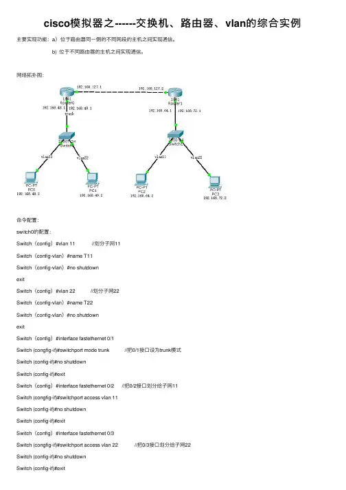
cisco模拟器之------交换机、路由器、vlan的综合实例主要实现功能:a)位于路由器同⼀侧的不同⽹段的主机之间实现通信。
b) 位于不同路由器的主机之间实现通信。
⽹络拓扑图:命令配置:switch0的配置:Switch(config)#vlan 11 //划分⼦⽹11Switch(config-vlan)#name T11Switch(config-vlan)#no shutdownexitSwitch(config)#vlan 22 //划分⼦⽹22Switch(config-vlan)#name T22Switch(config-vlan)#no shutdownexitSwitch(config)#interface fastethernet 0/1Switch (congfig-if)#switchport mode trunk //把0/1接⼝设为trunk模式Switch (config-if)#no shutdownSwitch (config-if)#exitSwitch(config)#interface fastethernet 0/2 //把0/2接⼝划分给⼦⽹11Switch (congfig-if)#switchport access vlan 11Switch (config-if)#no shutdownSwitch (config-if)#exitSwitch(config)#interface fastethernet 0/3Switch (congfig-if)#switchport access vlan 22 //把0/3接⼝划分给⼦⽹22Switch (config-if)#no shutdownSwitch (config-if)#exitSwitch1的配置:Switch(config)# vlan 11Switch(config-vlan)#name T11Switch(config-vlan)#no shutdownexitSwitch(config)# vlan 22Switch(config-vlan)#name T22Switch(config-vlan)#no shutdownexitSwitch(config)#interface fastethernet 0/1Switch (congfig-if)#switchport mode trunkSwitch (config-if)#no shutdownSwitch (config-if)#exitSwitch(config)#interface fastethernet 0/2Switch (congfig-if)#switchport access vlan 11Switch (config-if)#no shutdownSwitch (config-if)#exitSwitch(config)#interface fastethernet 0/3Switch (congfig-if)#switchport access vlan 22Switch (config-if)#no shutdownSwitch (config-if)#exitRouter0的配置:Switch (config)#int f0/1.1 //在0/1接⼝下划分⼦接⼝0/1.1Switch (config)#int f0/1.2 //在0/1接⼝下划分⼦接⼝0/1.2Switch(config)#interface fastethernet 0/1.1 //配置⼦接⼝0/1.1的路由信息Switch (congfig-subif)#encapsulation dot1Q 11 //单臂路由Switch (config-subif)#ip address 192.168.48.1 255.255.255.0Switch (config-subif)#exitSwitch(config)#interface fastethernet 0/1.2 //配置⼦接⼝0/1.2的路由信息Switch (congfig-subif)#encapsulation dot1Q 22 //单臂路由Switch (config-subif)#ip address 192.168.49.1 255.255.255.0Switch (config-subif)#exitSwitch(config)#interface fastethernet 0/1Switch (congfig-subif)#no shutdownSwitch (congfig-subif)#exitSwitch (congfig)#interface fastethernet 0/0 //配置接⼝0/0的路由信息Switch (config-subif)#ip address 192.168.127.1 255.255.255.0Switch (congfig-subif)#no shutdownSwitch (congfig-subif)#exitSwitch (config)#ip route 192.168.64.0 255.255.255.0 192.168.127.2 //配置静态路由协议Switch (config)#ip route 192.168.72.0 255.255.255.0 192.168.127.2Switch (config)#exitRouter1的配置:Switch (config)#int f0/1.1Switch (config)#int f0/1.2Switch(config)#interface fastethernet 0/1.1Switch (congfig-subif)#encapsulation dot1Q 11Switch (config-subif)#ip address 192.168.64.1 255.255.255.0Switch (config-subif)#exitSwitch(config)#interface fastethernet 0/1.2Switch (congfig-subif)#encapsulation dot1Q 22Switch (config-subif)#ip address 192.168.72.1 255.255.255.0Switch (config-subif)#exitSwitch(config)#interface fastethernet 0/1Switch (congfig-subif)#no shutdownSwitch (congfig-subif)#exitSwitch (congfig)#interface fastethernet 0/0Switch (config-subif)#ip address 192.168.127.2 255.255.255.0Switch (congfig-subif)#no shutdownSwitch (congfig-subif)#exitSwitch (config)#ip route 192.168.48.0 255.255.255.0 192.168.127.1Switch (config)#ip route 192.168.49.0 255.255.255.0 192.168.127.1Switch (config)#exit分别给各台主机配置ip以及其他信息:结果每台主机都可以通信。
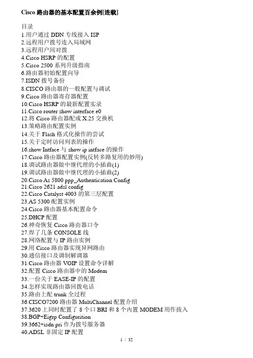
Cisco 路由器的基本配置百余例[连载]目录1.用户通过DDN专线接入ISP2.远程用户拨号连入局域网3.远程用户间对拨4.Cisco HSRP的配置5.Cisco 2500系列升级指南6.路由器初始配置向导7.ISDN 拨号备份8.CISCO路由器的一般配置与调试9.Cisco 路由器寄存器配置10.Cisco HSRP的最新配置实录11.Cisco router show interface e012.将Cisco 路由器配成X.25交换机13.策略路由配置实例14.关于Flash格式化操作的尝试15.关于定时访问列表的操作16.show Intface 与 show ip intface 的操作17.Cisco路由器配置实例(反转多路复用的妙用)18.调试路由器做中继代理的小插曲(1)19.调试路由器做中继代理的小插曲(2)20.Cisco As 5800 ppp_Authentication Config21.Cisco 2621 adsl config22.Cisco Catalyst 4003 的第三层配置23.AS 5300 配置实例24.Cisco 路由器基本配置命令25.DHCP 配置26.神奇恢复Cisco路由器口令27.焊了几条CONSOLE线28.网络配置与IP路由实例29.用Cisco路由器实现异网路由30.通信接口及调制解调器31.Cisco 路由器VOIP 设置命令详解32.配置Cisco路由器中的Modem33.一份关于EASE-IP的配置34.怎样实现路由器回拨电话35.路由上配trunk全过程36.CISCO7200路由器MultiChannel配置介绍37.3620上同时配置了8个口BRI和8个内置MODEM用作拔入38.BGP+Eigrp Configurition39.3662+isdn pri作为拨号服务器40.ADSL 非固定IP配置41.基于源地址的策略路由(new ver)42.通过Xmodem升级2610的IOS实例(02/4/3)43.完整的VOIP应用实例(02/4/7)44.一个3640的VOIP配置(02/4/7)45.浅谈路由器的安全配置(02/4/7)46.路由器配成桥的实例(02/4/7)47.CISCO 2505路由器HUB端口的安全性配置48.Cisco ADSL 配置说明49.Cisco 2620路由器的配置与维护50.Cisco 路由器在UNIX 下的备份恢复和更新51.ISDN PRI DDR配置实例52.ISDN 拨号备份的示例53.NAT 和 PAT 的应用配置54.NT下Cisco 2620拨号访问服务器的建立55.show controller e1 命令详解56.Cisco 路由器Callback 配置示例57.复杂的VOIP配置58.关键业务数据包优先发送及其在Cisco路由器中的实现59.广域网路由基本技术60.解决CISCO路由器Y2K的快捷方法61.利用Cisco2611路由器实现类163拨号拨入、拨出功能62.配置 IPSec - 路由器到PIX防火墙63.桥接技术巧解路由器配置IP问题64.双机热备的全面配置示例65.用路由器构建网络安全体系66.远程异步登陆Cisco 路由器67.路由器内的安全认证68.Call Back 命令解析69.张家口交通局及其收费站信息化案例70.APPN配置方法(包括DLSW)71.Cisco 2511 拨入配置72.SNA透过帧中继传输实例73.通过SSH实现Cisco路由器登录74.一个Snapshot配置的实例75.一个典型的PRI信令落地网关的配置(基于AS5300)76.一个典型的R2(中国一号)信令上车网关的配置(基于AS5300)77.Cisco 路由器动态和静态地址转换78.两端口路由器地址转换的例子79.Cat 6509 NAT 实例80.实战手记之高级NAT(Checkpoint)81.实战手记之PPOE+NAT82.代理服务器、路由器配置案例83.配置Cisco 路由器中的Modem84.Cisco 路由器AUX 背对背配置实例85.Cisco 路由器备份配置语句说明86.MPLS 配置实例87.Tunnel的具体配置88.IP Sec VPN 配置实例89.STM-1的配置及有关SDH90.透明桥的配置实例91.VOIP 配置解析92.CISCO7200路由器MultiChannel配置介绍93.Call Back 配置语句解析94.3550 配置清单95.3550 EMI DHCP 服务器配置96.3640的CE1划分绑定及做3层97.3640 远程接入配置98.Cisco 2500 远程接入服务器配置99.Cisco 路由器安全基础100.BGP 配置案例101.Cisco 7010 与 5509的HSRP配置实例102.IP 路由协议的配置实例103.7206路由器升级104.7500路由器升级105.7507路由器内存升级106.在IOS环境下配置DHCP服务(6500)107.Native IOS 使用心得1.用户通过DDN专线接入ISP对于一个局域网的外连,有很多种方式DDN专线就是其中的一种(具体外连方式请见网络基础部分).在下面的实例中介绍了蓝色家园内部局域网接入当地ISP的配置.蓝色家园内部局域网:10.1.8.0/24蓝色家园路由器的Ethernet 0:10.1.8.1/24Serial 0: 192.168.0.1/30ISP路由器Serial 0: 192. 168.0.2/30具体拓扑图如下:也许Cisco操作系统的玄虚性以及其在市场中的占有率,决定了人们对其技术的一种仰慕,甚至想把自己的技术奋斗目标与Cisco 绑定.但是,技术总归是技术,一切都是从头开始的.下面给出蓝色家园路由器的基本配置1.route>en 进入特权状态2.route#config t 通过端口进行配置3.在配置状态下给出E0/S0的IP地址#int e0/0#ip add 10.1.8.1 255.255.255.0#no shut#int s0/0#ip add 192.168.0.1 255.255.255. 252#en ppp (允许在专线上发送ppp包,如果不写,对于两端都是Cisco路由器是没问题的,会默认为Cisco 自己的打包方式)# no shut4.给出蓝色家园到ISP的路由,因为蓝色家园只有一个出路,所以给出静态路由#ip route 0.0.0.0 0.0.0.0 192. 168.0.2或者#ip route 0.0.0.0 0.0.0.0 seri al 05.为了保证远程管理的Telnet 必须给出登陆用户#line vty 0 4#password bluegarden6.Ctrl+Z退出特权配置状态wr将配置写入路由器即可当然以上只是一个基本配置,能够保证数据通道的畅通.但是并没有充分利用路由器的功能,例如:NAT、安全等等。

思科交换机vrrpmstp配置实例一、组网需求1、witcha、witchb选用两台锐捷的5750;witchc、hwichd选用锐捷的3750和37602、全网共有两个业务vlan,为vlan10、vlan203、Switcha、witchb都分别对两vlan起用两vrrp组,实现两组的业务的负载分担和备份。
4、Switcha、witchb、witchc、witchd都起用mtp多生成数协议,并且所有设备都属于同一个mt域,且实例映射一致(vlan10映射实例1、vlan20映射实例2其他vlan映射默认实例0)。
5、Vlan10业务以witcha为根桥;vlan20业务以witchb为根桥;实现阻断网络环路,并能实现不同vlan数据流负载分担功能。
二、组网图三、配置步骤Switcha配置:1#howrunBuildingconfiguration...Currentconfiguration:1651byte!verionRGNOS10.2.00(2),Releae(29287)(TueDec2520:39:14CST2007-ngcf49)hotname1co-operateenable!!!vlan1!vlan10!vlan20!!noervicepaword-encryption!panning-tree开启生成树(默认为mtp)panning-treemtconfiguration进入mt配置模式reviion1指定MSTreviionnumber为1nameregion1指定mt配置名称intance0vlan1-9,11-19,21-4094缺省情况下vlan都属于实例0intance1vlan10手工指定vlan10属于实例1intance2vlan20手工指定vlan20属于实例2panning-treemt1priority0指定实例1的优先级为0(为根桥)panning-treemt2priority4096指定实例2的优先级为4096interfaceGigabitEthernet0/1witchportaccevlan10配置g0/1属于vlan10! interfaceGigabitEthernet0/2witchportaccevlan20配置g0/2属于vlan20!interfaceGigabitEthernet0/3!..interfaceGigabitEthernet0/24设置g0/24为trunk接口且允许vlan10/20通过witchportmodetrunk!interfaceVLAN10创建vlan10vi接口ipaddre192.168.10.1255.255.255.0配置ip地址vrrp1priority120配置vrrp组1优先级为120vrrp1ip192.168.10.254配置vrrp组1虚拟ip地址为192.168.10.254!interfaceVLAN20创建vlan20vi接口ipaddre192.168.20.1255.255.255.0配置ip地址vrrp2ip192.168.20.254配置vrrp组2虚拟ip地址为192.168.20.254默认vrrp组的优先级为100默认不显示!linecon0linevty04login1#howvlanVLANNameStatuPort-------------------------------------------------------------------------------1VLAN0001STATICGi0/3,Gi0/4,Gi0/5,Gi0/6Gi0/7,Gi0/8,Gi0/9,Gi0/10Gi0/11,Gi0/12,Gi0/13,Gi0/14Gi0/15,Gi0/16,Gi0/17,Gi0/18Gi0/19,Gi0/20,Gi0/21,Gi0/22Gi0/23,Gi0/2410VLAN0010STATICGi0/1,Gi0/2420VLAN0020STATICGi0/2,Gi0/24Switchb配置:2#howrunBuildingconfiguration...Currentconfiguration:1607byte!verionRGNOS10.2.00(2),Releae(27932)(ThuDec1310:32:09CST2007-ngcf31)hotname2!!!vlan1!vlan10!vlan20!!noervicepaword-encryption!panning-treepanning-treemtconfigurationreviion1nameregion1intance0vlan1-9,11-19,21-4094intance1vlan10intance2vlan20panning-treemt1priority4096panning-treemt2priority0interfaceGigabitEthernet0/1witchportaccevlan10!interfaceGigabitEthernet0/2witchportaccevlan20!..interfaceGigabitEthernet0/24witchportmodetrunk! interfaceVLAN10ipaddre192.168.10.2255.255.255.0vrrp1ip192.168.10.254!interfaceVLAN20ipaddre192.168.20.2255.255.255.0vrrp2priority120vrrp2ip192.168.20.254!linecon0linevty04login!!end2#howvlanVLANNameStatuPort--------------------------------------------------------------------------------1VLAN0001STATICGi0/3,Gi0/4,Gi0/5,Gi0/6Gi0/7,Gi0/8,Gi0/9,Gi0/10Gi0/11,Gi0/12,Gi0/13,Gi0/14Gi0/15,Gi0/16,Gi0/17,Gi0/18Gi0/19,Gi0/20,Gi0/21,Gi0/22Gi0/23,Gi0/2410VLAN0010STATICGi0/1,Gi0/2420VLAN0020STATICGi0/2,Gi0/24Switchc配置:3#howrunBuildingconfiguration...Currentconfiguration:1540byte!verionRGNOS10.2.00(2),Releae(28794)(FriDec2109:27:15CST2007-ngcf32)hotname3!vlan10!!ervicepaword-encryption!panning-treepanning-treemtconfigurationreviion1nameregion1intance0vlan1-9,11-19,21-4094intance1vlan10intance2vlan20 panning-treemt1priority0panning-treemt2priority4096interfaceFatEthernet0/1witchportaccevlan10!interfaceFatEthernet0/2witchportaccevlan10!..interfaceGigabitEthernet0/25!interfaceGigabitEthernet0/26!interfaceGigabitEthernet0/27!interfaceGigabitEthernet0/28!interfaceVLAN10ipaddre192.168.10.3255.255.255.0!iproute0.0.0.00.0.0.0192.168.10.254!!linecon0linevty04loginSwitchd配置:Buildingconfiguration...Currentconfiguration:1066byte!verionRGNOS10.2.00(2),Releae(27932)(ThuDec1310:31:41CST2007-ngcf32)hotname4!vlan1!vlan20!!noervicepaword-encryption!panning-treepanning-treemtconfigurationreviion1nameregion1intance0vlan1-9,11-19,21-4094intance1vlan10intance2vlan20panning-treemt1priority4096panning-treemt2priority0interfaceGigabitEthernet0/1witchportaccevlan20!interfaceGigabitEthernet0/2witchportaccevlan20!..interfaceGigabitEthernet0/12!interfaceVLAN20ipaddre192.168.20.3255.255.255.0!!!!iproute0.0.0.00.0.0.0192.168.20.254!!linecon0linevty04login!四、查看vrrp、mtp信息Switcha信息:1#howvrrp查看vrrp信息VLAN10-Group1StateiMaterVirtualIPaddrei192.168.10.254configuredVirtualMACaddrei0000. 5e00.0101Advertiementintervali1ecPreemptionienabledmindelayi0ecP riorityi120MaterRouteri192.168.10.1(local),priorityi120MaterAdvertiemen tintervali1ecMaterDownintervali3ecVLAN20-Group2StateiBackup VirtualIPaddrei192.168.20.254configuredVirtualMACaddrei0000. 5e00.0102Advertiementintervali1ecPreemptionienabledmindelayi0ecP riorityi100MaterRouteri192.168.20.2,priorityi120MaterAdvertiementinterv ali1ecMaterDownintervali3ec1#1#1#1#howpanning-treeinterfacegigabitEthernet0/1查看g0/1接口tp 状态信息PortAdminPortFat:DiabledPortOperPortFat:DiabledPortAdminAuto Edge:EnabledPortOperAutoEdge:DiabledPortAdminLinkType:auto PortOperLinkType:point-to-pointPortBPDUGuard:DiabledPortBPDUFilter:Diabled######MST0vlanmapped:1-9,11-19,21-4094PortState:forwardingPortPriority:128PortDeignatedRoot:8000.001a.a909.8fe0PortDeignatedCot:0PortDeignatedBridge:8000.00d0.f836.ed70PortDeignatedPort:800 1PortForwardTranition:6PortAdminPathCot:200000PortOperPathCot:20 0000PortRole:deignatedPort######MST1vlanmapped:10PortState:forwardingPortPriority:128 PortDeignatedRoot:0001.00d0.f823.ef82PortDeignatedCot:0PortDeignatedBridge:0001.00d0.f823.ef82PortDeignatedPort:800 1PortForwardTranition:5PortAdminPathCot:200000PortOperPathCot:20 0000PortRole:rootPort######MST2vlanmapped:20PortState:forwardingPortPriority:128 PortDeignatedRoot:0002.001a.a909.8fe0PortDeignatedCot:0PortDeignatedBridge:1002.00d0.f836.ed70PortDeignatedPort:800 1PortForwardTranition:4PortAdminPathCot:200000PortOperPathCot:20 0000PortRole:deignatedPort1#1#1#howpanning-treeinterfacegigabitEthernet0/2查看g0/2接口tp 状态信息PortAdminPortFat:DiabledPortOperPortFat:DiabledPortAdminAuto Edge:EnabledPortOperAutoEdge:DiabledPortAdminLinkType:auto PortOperLinkType:point-to-pointPortBPDUGuard:DiabledPortBPDUFilter:Diabled######MST0vlanmapped:1-9,11-19,21-4094PortState:forwardingPortPriority:128PortDeignatedRoot:8000.001a.a909.8fe0PortDeignatedCot:0PortDeignatedBridge:8000.00d0.f836.ed70PortDeignatedPort:800 2PortForwardTranition:5PortAdminPathCot:20000PortOperPathCot:200 00PortRole:deignatedPort######MST1vlanmapped:10PortState:forwardingPortPriority:128 PortDeignatedRoot:0001.00d0.f823.ef82PortDeignatedCot:0PortDeignatedBridge:0001.00d0.f836.ed70PortDeignatedPort:800 2PortForwardTranition:4PortAdminPathCot:20000PortOperPathCot:200 00PortRole:deignatedPort######MST2vlanmapped:20PortState:dicardingPortPriority:128 PortDeignatedRoot:0002.001a.a909.8fe0PortDeignatedCot:0 PortDeignatedBridge:0002.00d0.f8d7.ae12PortDeignatedPort:8002 PortForwardTranition:3PortAdminPathCot:20000PortOperPathCot: 20000PortRole:alternatePort1#1#1#howpanning-treeinterfacegigabitEthernet0/24g0/24接口tp状态信息PortAdminPortFat:DiabledPortOperPortFat:DiabledPortAdminAuto Edge:EnabledPortOperAutoEdge:DiabledPortAdminLinkType:auto PortOperLinkType:point-to-pointPortBPDUGuard:DiabledPortBPDUFilter:Diabled######MST0vlanmapped:1-9,11-19,21-4094PortState:forwardingPortPriority:128PortDeignatedRoot:8000.001a.a909.8fe0PortDeignatedCot:0PortDeignatedBridge:8000.001a.a909.8fe0PortDeignatedPort:801 8PortForwardTranition:5PortAdminPathCot:20000PortOperPathCot:200 00PortRole:rootPort######MST1vlanmapped:10PortState:forwardingPortPriority:128 PortDeignatedRoot:0001.00d0.f823.ef82PortDeignatedCot:0PortDeignatedBridge:0001.00d0.f836.ed70PortDeignatedPort:801 8PortForwardTranition:5PortAdminPathCot:20000PortOperPathCot:200 00PortRole:deignatedPort######MST2vlanmapped:20PortState:forwardingPortPriority:128 PortDeignatedRoot:0002.001a.a909.8fe0PortDeignatedCot:0PortDeignatedBridge:0002.001a.a909.8fe0PortDeignatedPort:801 8PortForwardTranition:4PortAdminPathCot:20000PortOperPathCot:200 00PortRole:rootPort1#Switchb信息:2#howvrrpVLAN10-Group1StateiBackupVirtualIPaddrei192.168.10.254configuredVirtualMACaddrei0000. 5e00.0101Advertiementintervali1ecPreemptionienabledmindelayi0ecP riorityi100MaterRouteri192.168.10.1,priorityi120MaterAdvertiementinterv ali1ecMaterDownintervali3ecVLAN20-Group2StateiMaterVirtualIPaddrei192.168.20.254configuredVirtualMACaddrei0000. 5e00.0102Advertiementintervali1ecPreemptionienabledmindelayi0ecP riorityi120MaterRouteri192.168.20.2(local),priorityi120MaterAdvertiemen tintervali1ecMaterDownintervali3ec2#2#2#2#2#2#2#howpanning-treeinterfacegigabitEthernet0/1PortAdminPortFat:DiabledPortOperPortFat:DiabledPortAdminAuto Edge:EnabledPortOperAutoEdge:DiabledPortAdminLinkType:auto PortOperLinkType:point-to-pointPortBPDUGuard:DiabledPortBPDUFilter:Diabled######MST0vlanmapped:1-9,11-19,21-4094PortState:forwardingPortPriority:128PortDeignatedRoot:8000.001a.a909.8fe0PortDeignatedCot:0PortDeignatedBridge:8000.001a.a909.8fe0PortDeignatedPort:800 1PortForwardTranition:1PortAdminPathCot:200000PortOperPathCot:20 0000PortRole:deignatedPort######MST1vlanmapped:10PortState:forwardingPortPriority:128 PortDeignatedRoot:0001.00d0.f823.ef82PortDeignatedCot:0PortDeignatedBridge:0001.00d0.f823.ef82PortDeignatedPort:800 2PortForwardTranition:2PortAdminPathCot:200000PortOperPathCot:20 0000PortRole:rootPort######MST2vlanmapped:20PortState:forwardingPortPriority:128PortDeignatedBridge:0002.001a.a909.8fe0PortDeignatedPort:800 1PortForwardTranition:1PortAdminPathCot:200000PortOperPathCot:20 0000PortRole:deignatedPort2#2#2#2#howpanning-treeinterfacegigabitEthernet0/2PortAdminPortFat:DiabledPortOperPortFat:DiabledPortAdminAuto Edge:EnabledPortOperAutoEdge:DiabledPortAdminLinkType:auto PortOperLinkType:point-to-pointPortBPDUGuard:DiabledPortBPDUFilter:Diabled######MST0vlanmapped:1-9,11-19,21-4094PortState:forwardingPortPriority:128PortDeignatedRoot:8000.001a.a909.8fe0PortDeignatedCot:0PortDeignatedBridge:8000.001a.a909.8fe0PortDeignatedPort:800 2PortForwardTranition:1PortAdminPathCot:20000PortOperPathCot:200 00PortRole:deignatedPort######MST1vlanmapped:10PortState:forwardingPortPriority:128 PortDeignatedRoot:0001.00d0.f823.ef82PortDeignatedCot:0PortDeignatedBridge:1001.001a.a909.8fe0PortDeignatedPort:800 2PortForwardTranition:2PortAdminPathCot:20000PortOperPathCot:200 00PortRole:deignatedPort######MST2vlanmapped:20PortState:forwardingPortPriority:128PortDeignatedBridge:0002.001a.a909.8fe0PortDeignatedPort:800 2PortForwardTranition:1PortAdminPathCot:20000PortOperPathCot:200 00PortRole:deignatedPort2#2#2#2#2#howpanning-treeinterfacegigabitEthernet0/24PortAdminPortFat:DiabledPortOperPortFat:DiabledPortAdminAuto Edge:EnabledPortOperAutoEdge:DiabledPortAdminLinkType:auto PortOperLinkType:point-to-pointPortBPDUGuard:DiabledPortBPDUFilter:Diabled######MST0vlanmapped:1-9,11-19,21-4094PortState:forwardingPortPriority:128PortDeignatedRoot:8000.001a.a909.8fe0PortDeignatedCot:0PortDeignatedBridge:8000.001a.a909.8fe0PortDeignatedPort:801 8PortForwardTranition:1PortAdminPathCot:20000PortOperPathCot:200 00PortRole:deignatedPort######MST1vlanmapped:10PortState:dicardingPortPriority:128 PortDeignatedRoot:0001.00d0.f823.ef82PortDeignatedCot:0PortDeignatedBridge:0001.00d0.f836.ed70PortDeignatedPort:801 8PortForwardTranition:1PortAdminPathCot:20000PortOperPathCot:200 00PortRole:alternatePort。


Cisco 2811企业网络配置案例网络, Cisco, 企业一、DHCP服务1.全局地址池地址池名称:global地址段:192.168.0.0 255.255.255.0默认网关:192.168.0.1DNS:202.106.0.20,202.106.116.1地址租期:3天ip dhcp pool globalnetwork 192.168.0.0 255.255.255.0default-router 192.168.0.1dns-server 202.106.0.20 202.106.116.1lease 32.固定地址池为每个员工建立一个DHCP 地址池,并根据员工姓名对地址池进行命名,根据MAC地址进行IP地址分配,如:ip dhcp pool staffnameAhost 192.168.0.11 255.255.255.0client-identifier 0108.0046.0ef8.aeip dhcp pool staffnameBhost 192.168.0.12 255.255.255.0client-identifier 0100.115b.518c.a2注意,在MAC地址前面多了个01,然后每4位用一个点分隔。
3.未分配的IP地址地址段:192.168.0.60 到192.168.0.254ip dhcp excluded-address 192.168.0.60 192.168.0.254二设置IP地址与MAC地址绑定绑定特权IP地址与MAC地址的关系,保证特权IP不被占用。
arp 192.168.0.2 0000.e897.444c ARPAarp 192.168.0.3 0000. 00e8.9734 ARPA…………绑定其他IP地址与MAC地址的关系,保证IP不被盗用。
arp 192.168.0.9 ef00.abcd.4444 ARPA……………………arp 192.168.0.254 ef00.abcd.4444 ARPA三、PAT转换访问控制列表100的策略:允许192.168.0.2、192.168.0.3、192.168.0.4、192.168.0.5、192.168.0.6、192.168.0.7、192.168.0.8七个特权地址任意访问公网。

二层交换机配置案例(配置2层交换机可远程管理):Switch>Switch>en进入特权模式Switch#config进入全局配置模式Switch(config)#hostname2ceng更改主机名为2ceng2ceng(config)#interfacevlan1进入VLAN12ceng(config-if)#noshut激活VLAN12ceng(config-if)#exit退出到全局配置模式2ceng(config)#interfacevlan2创建VLAN22ceng(config-if)#noshut激活VLAN22ceng(config-if)#exit退出到全局配置模式2ceng(config)#interfacevlan3创建VLAN32ceng(config-if)#noshut激活VLAN32ceng(config-if)#ipaddress2ceng(config-if)#exit2ceng(config)#interfacerangefa0/1-122ceng(config-if-range)#exit2ceng(config)#interfacerangefa0/13-23telnet2ceng(config)#exit2ceng#wr保存配置Buildingconfiguration...[OK]三层(或多层)交换机配置实例:Switch>Switch>enSwitch#configConfiguringfromterminal,memory,ornetwork[terminal]? Enterconfigurationcommands,oneperline.EndwithCNTL/Z. Switch(config)#hostname3ceng3ceng(config)#interfacevlan13ceng(config-if)#noshut3ceng(config-if)#exit3ceng(config)#interfacevlan23ceng(config-if)#noshut3ceng(config-if)#exit3ceng(config)#interfacevlan33ceng(config-if)#noshut3ceng(config-if)#ipaddress3ceng(config-if)#descriptionguanli描述vlan3为管理3ceng(config-if)#exit3ceng(config)#interfacerangefa0/1-123ceng(config-if-range)#switchportmodeaccess3ceng(config-if-range)#switchaccessvlan13ceng(config-if-range)#exit3ceng(config)#interfacerangefa0/13-243ceng(config-if-range)#switchaccessvlan23ceng(config-if-range)#exit3ceng(config)#ipdhcppoolvlan1设置VLAN1DHCP3ceng(dhcp-config)#network设置DHCP的网段3ceng(dhcp-config)#dns-server设置3ceng(dhcp-config)#default-router设置3ceng(dhcp-config)#exit3ceng(config)#ipdhcppoolvlan23ceng(dhcp-config)#network3ceng(dhcp-config)#dns-server3ceng(config)#exit3ceng#wrBuildingconfiguration...[OK]。
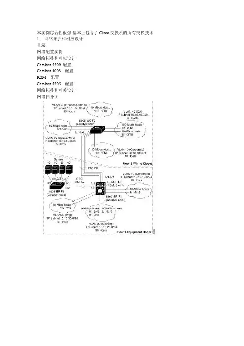
本实例综合性很强,基本上包含了Cisco交换机的所有交换技术1.网络拓扑和相应设计目录:网络配置实例网络拓扑和相应设计Catalyst 5509 配置Catalyst 4003配置RSM配置Catalyst 5505配置网络拓扑和相关设计网络拓扑图2.Catalyst 5509 的配置下面列出Catalyst 5509 的基本配置Enter password:Console> enableEnter password:Console> (enable) set system name 5509-ER-F1System name set.5509-ER-F1> (enable) set system location 1st Floor Equipment Room System location set.5509-ER-F1> (enable) set system contact sysadmin@ System contact set.5509-ER-F1> (enable) set time 04/30/1999 9:30:00Fri Apr 30 1999, 09:30:005509-ER-F1> (enable) set passwordEnter old password:Enter new password:Retype new password:Password changed.5509-ER-F1> (enable) set enablepassEnter old password:Enter new password:Retype new password:Password changed.5509-ER-F1> (enable) set banner motd %5509-ER-F1 (Catalyst 5509)Access Restricted%MOTD banner set5509-ER-F1> (enable) set interface sc0 10.10.1.10/24 Interface sc0 IP address set.5509-ER-F1> (enable) set ip route default 10.10.1.1Route added.5509-ER-F1> (enable) set ip dns server 10.10.10.10010.10.10.100 added to DNS server table as primary server. 5509-ER-F1> (enable) set ip dns domain Default DNS domain name set to 5509-ER-F1> (enable) set ip dns enableDNS is enabled5509-ER-F1> (enable) set vtp domain BigCorp mode server VTP domain BigCorp modified5509-ER-F1> (enable) set vlan 10 name CorporateVlan 10 configuration successful5509-ER-F1> (enable) set vlan 20 name DevEngVlan 20 configuration successful5509-ER-F1> (enable) set vlan 30 name MfgVlan 30 configuration successful5509-ER-F1> (enable) set vlan 40 name QAVlan 40 configuration successful5509-ER-F1> (enable) set vlan 50 name Finance&Admin Vlan 50 configuration successful5509-ER-F1> (enable) set vlan 60 name Sales&MktgVlan 60 configuration successful5509-ER-F1> (enable) set module name 1 Supervisor III Module name set.5509-ER-F1> (enable) set port flowcontrol 1/1-2 send off Ports 1/1-2 flow control send administration status set to off (ports will not send flowcontrol to far end)5509-ER-F1> (enable) set port flowcontrol 1/1-2 receive off Ports 1/1-2 flow control receive administration status set to off (ports will not allow far end to send flowcontrol)5509-ER-F1> (enable) set port negotiation 1/1-2 enable Ports 1/1-2 negotiation enabled5509-ER-F1> (enable) set port name 1/1-2 GEC 802.1Q Trunk Ports 1/1-2 name set.5509-ER-F1> (enable) set port channel 1/1-2 desirablePort(s) 1/1-2 channel mode set to desirable.5509-ER-F1> (enable) set trunk 1/1 desirable dot1qPort(s) 1/1 trunk mode set to desirable.Port(s) 1/1 trunk type set to dot1q.5509-ER-F1> (enable) set module name 3 RSM (RSM-ER-F1) Module name set.5509-ER-F1> (enable) set module name 5 Fast Ether Uplinks Module name set.5509-ER-F1> (enable) set port name 5/1-4 FEC ISL Trunk Ports 5/1-4 name set.5509-ER-F1> (enable) set port speed 5/1-4 100Ports 5/1-4 transmission speed set to 100Mbps.5509-ER-F1> (enable) set port duplex 5/1-4 fullPorts 5/1-4 set to full-duplex.5509-ER-F1> (enable) set port flowcontrol 5/1-4 send offPorts 5/1-4 flow control send administration status set to off (ports will not send flowcontrol to far end)5509-ER-F1> (enable) set port flowcontrol 5/1-4 receive off Ports 5/1-4 flow control receive administration status set to off (ports will not allow far end to send flowcontrol)5509-ER-F1> (enable) set port negotiation 5/1-4 enablePorts 5/1-4 negotiation enabled5509-ER-F1> (enable) set port channel 5/1-4 desirablePort(s) 5/1-4 channel mode set to desirable.5509-ER-F1> (enable) set trunk 5/1 desirable islPort(s) 5/1 trunk mode set to desirable.Port(s) 5/1 trunk type set to isl.5509-ER-F1> (enable) set module name 6 DevEng 100Mb Hosts Module name set.5509-ER-F1> (enable) set port name 6/1 DE Sparc UltraPort 6/1 name set.5509-ER-F1> (enable) set port name 6/2-7 DE Sparc20Ports 6/2-7 name set.5509-ER-F1> (enable) set port name 6/8-12 DE NT Workstation Ports 6/8-12 name set.5509-ER-F1> (enable) set port speed 6/1-12 100Ports 6/1-12 transmission speed set to 100Mbps.5509-ER-F1> (enable) set port duplex 6/1-12 fullPorts 6/1-12 set to full-duplex.5509-ER-F1> (enable) set port flowcontrol 6/1-12 send desired Ports 6/1-12 flow control send administration status set to desired(ports will send flowcontrol to far end if far end supports it)5509-ER-F1> (enable) set port flowcontrol 6/1-12 receive desiredPorts 6/1-12 flow control receive administration status set to desired (ports will allow far end to send flowcontrol if far end supports it)5509-ER-F1> (enable) set port channel 6/1-12 offPort(s) 6/1-12 channel mode set to off.5509-ER-F1> (enable) set trunk 6/1-12 offPort(s) 6/1-12 trunk mode set to off.5509-ER-F1> (enable) set spantree portfast 6/1-12 enableWarning: Spantree port fast start should only be enabled on ports connected to a single host. Connecting hubs, concentrators, switches, bridges, etc. to a fast start port can cause temporary spanning tree loops. Use with caution. Spantree ports 6/1-12 fast start enabled.5509-ER-F1> (enable) set vlan 20 6/1-12VLAN 20 modified.VLAN 1 modified.VLAN Mod/Ports---- -----------------------201/1-25/1-46/1-125509-ER-F1> (enable) set module name 7 Corp/Mfg 10Mb Hosts Module name set.5509-ER-F1> (enable) set port name 7/1-12 Corp Win98 PCPorts 7/1-12 name set.5509-ER-F1> (enable) set port name 7/13-48 Mfg Win98 PCPorts 7/13-48 name set.5509-ER-F1> (enable) set port duplex 7/1-48 fullPorts 7/1-48 set to full-duplex.5509-ER-F1> (enable) set spantree portfast 7/1-48 enableWarning: Spantree port fast start should only be enabled on ports connected to a single host. Connecting hubs, concentrators, switches, bridges, etc. to a fast start port can cause temporary spanning tree loops. Use with caution. Spantree ports 7/1-48 fast start enabled.5509-ER-F1> (enable) set vlan 10 7/1-12VLAN 10 modified.VLAN 1 modified.VLAN Mod/Ports---- -----------------------101/1-25/1-47/1-125509-ER-F1> (enable) set vlan 30 7/13-48VLAN 30 modified.VLAN 1 modified.VLAN Mod/Ports---- -----------------------301/1-25/1-47/13-485509-ER-F1> (enable) set module name 8 DevEng 10Mb HostsModule name set.5509-ER-F1> (enable) set port name 8/1-48 DevEng WinNT PCPorts 8/1-48 name set.5509-ER-F1> (enable) set port duplex 8/1-48 fullPorts 8/1-48 set to full-duplex.5509-ER-F1> (enable) set spantree portfast 8/1-48 enableWarning: Spantree port fast start should only be enabled on ports connected to a single host. Connecting hubs, concentrators, switches, bridges, etc. to a fast start port can cause temporary spanning tree loops. Use with caution. Spantree ports 8/1-48 fast start enabled.5509-ER-F1> (enable) set vlan 20 8/1-48VLAN 20 modified.VLAN 1 modified.VLAN Mod/Ports---- -----------------------201/1-25/1-46/1-128/1-485509-ER-F1> (enable) set module name 9 DevEng 10Mb HostsModule name set.5509-ER-F1> (enable) set port name 9/1-48 DevEng WinNT PCPorts 9/1-48 name set.5509-ER-F1> (enable) set port duplex 9/1-48 fullPorts 9/1-48 set to full-duplex.5509-ER-F1> (enable) set spantree portfast 9/1-48 enableWarning: Spantree port fast start should only be enabled on ports connected to a single host. Connecting hubs, concentrators, switches, bridges, etc. to a fast start port can cause temporary spanning tree loops. Use with caution. Spantree ports 9/1-48 fast start enabled.5509-ER-F1> (enable) set vlan 20 9/1-48VLAN 20 modified.VLAN 1 modified.VLAN Mod/Ports---- ----------------------- 201/1-25/1-46/1-128/1-489/1-485509-ER-F1> (enable)。

第1篇一、实验目的1. 掌握思科网络设备的配置方法,包括交换机、路由器等;2. 熟悉思科网络设备的连接方式,如VLAN、STP等;3. 了解思科网络设备的网络管理功能;4. 培养实际动手操作能力和网络规划能力。
二、实验环境1. 硬件设备:思科交换机、路由器、计算机等;2. 软件设备:思科Packet Tracer模拟软件;3. 实验拓扑:楼宇网络拓扑。
三、实验内容1. 交换机配置(1)交换机的基本配置:配置交换机名称、描述、管理IP地址等;(2)VLAN配置:创建VLAN,配置VLAN ID和名称,将端口划分到对应VLAN;(3)STP配置:配置生成树协议,防止网络环路。
2. 路由器配置(1)路由器的基本配置:配置路由器名称、描述、管理IP地址等;(2)静态路由配置:配置静态路由,实现不同网络之间的互通;(3)动态路由配置:配置OSPF路由协议,实现路由器之间的动态路由学习。
3. 网络管理(1)查看设备信息:查看交换机、路由器的配置信息、运行状态等;(2)配置设备监控:设置设备监控,实时查看网络流量、设备性能等;(3)配置设备备份:设置设备配置备份,防止设备配置丢失。
4. 楼宇网络规划(1)分析楼宇网络需求:了解楼宇网络规模、网络设备需求等;(2)设计网络拓扑:根据需求设计楼宇网络拓扑;(3)配置网络设备:根据拓扑图配置网络设备,实现楼宇网络互通。
四、实验步骤1. 使用Packet Tracer软件创建实验拓扑,包括交换机、路由器、计算机等设备;2. 配置交换机,包括基本配置、VLAN配置、STP配置等;3. 配置路由器,包括基本配置、静态路由配置、动态路由配置等;4. 配置网络管理,包括设备信息查看、设备监控、设备备份等;5. 分析楼宇网络需求,设计网络拓扑;6. 根据拓扑图配置网络设备,实现楼宇网络互通;7. 测试网络连通性,确保楼宇网络正常运行。
五、实验结果与分析1. 实验结果:通过配置交换机、路由器等设备,成功实现了楼宇网络的互通;2. 实验分析:在实验过程中,掌握了思科网络设备的配置方法,熟悉了网络规划与设计的基本步骤,提高了实际动手操作能力和网络规划能力。
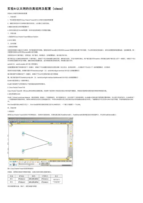
实验4-以太⽹的仿真组⽹及配置(cisco)实验4以太⽹的仿真组⽹及配置⼀、实验⽬的1.学会使⽤仿真软件Cisco Packet Tracer进⾏以太⽹的仿真组⽹和配置2.掌握交换机命令⾏各种操作模式的区别,以及模式之间的切换。
3.掌握交换机端⼝的常⽤配置命令4. 利⽤交换机进⾏VLAN的配置,加深对虚拟局域⽹⼯作原理的理解。
⼆、实验设备1.仿真软件Cisco Packet Tracer或Boson NetSim2.台式计算机三、技术原理1.交换机的管理交换机的管理⽅式基本分为两种:带内管理和带外管理。
管理员使⽤Telnet通过交换机的Console⼝管理交换机属于带外管理,不占⽤交换机的⽹络接⼝,其特点是需要使⽤配置线缆,近距离配置。
第⼀次配置交换机时必须利⽤Console端⼝进⾏配置。
交换机的命令⾏操作模式,主要包括:⽤户模式、特权模式、全局配置模式、端⼝模式等⼏种。
⽤户模式进⼊交换机后得到的第⼀个操作模式,该模式下可以简单查看交换机的软、硬件版本信息,并进⾏简单的测试。
⽤户模式提⽰符为switch> 特权模式由⽤户模式进⼊的下⼀级模式,该模式下可以对交换机的配置⽂件进⾏管理,查看交换机的配置信息,进⾏⽹络的测试和调试等。
特权模式提⽰符为switch# (注:switch>enable 命令进⼊特权模式)全局配置模式属于特权模式的下⼀级模式,该模式下可以配置交换机的全局性参数(如主机名、登录信息等)。
在该模式下可以进⼊下⼀级的配置模式,对交换机具体的功能进⾏配置。
全局模式提⽰符为switch(config)# (注:switch#configure terminal 命令进⼊全局配置模式)端⼝模式属于全局模式的下⼀级模式,该模式下可以对交换机的端⼝进⾏参数配置。
端⼝模式提⽰符为switch(config-if)# (注:switch(config)# interface fastethernet0/5 命令进⼊全局配置模式)Exit命令是退回到上⼀级操作模式。
实训报告实训一路由基本配置1、实验目的:路由器基本配置及ip设置2、拓扑结构图Router0 fa0/0: 192.168.11.1Fa0/1:192.168.1.1Router1 fa0/0: 192.168.11.2Fa0/1:192.168.2.1Znn1:192.168.1.2Znn2:192.168.2.23、实验步骤Router1Router>en 用户模式进入特权模式Router#conf t 特权模式进入全局模式Enter configuration commands, one per line. End with CNTL/Z.Router(config)#host rznn1 改名字为rznn1rznn1(config)#int fa0/0 进入fa0/0端口rznn1(config-if)#ip add 192.168.11.1 255.255.255.0 设置ip地址rznn1(config-if)#no sh 激活rznn1(config)#int fa0/1rznn1(config-if)#ip add 192.168.1.1 255.255.255.0rznn1(config-if)#no shrznn1(config-if)#exitrznn1(config)#exitrznn1#copy running-config startup-config 保存Destination filename [startup-config]? startup-configrznn1#conf trznn1(config)#enable secret password 222 设置密文rznn1#show ip interface b 显示Interface IP-Address OK? Method Status Protocol FastEthernet0/0 192.168.11.1 YES manual up up FastEthernet0/1 192.168.1.1 YES manual up upVlan1 unassigned YES manual administratively down downrouter 2outer>enRouter#conf tEnter configuration commands, one per line. End with CNTL/Z.Router(config)#host rznn2rznn2(config)#int fa0/0rznn2(config-if)#ip add 192.168.11.2 255.255.255.0rznn2(config-if)#no shrznn2(config)#int fa0/1rznn2(config-if)#ip add 192.168.2.1 255.255.255.0rznn2(config-if)#no shRznn2#copy running-config startup-config 保存Destination filename [startup-config]? startup-configrznn2(config-if)#exitrznn2(config)#exitrznn2#conf trznn2(config)#enable secret 222rznn2#show ip interface bInterface IP-Address OK? Method Status Protocol FastEthernet0/0 192.168.11.2 YES manual up up FastEthernet0/1 192.168.2.1 YES manual up upVlan1 unassigned YES manual administratively down down实训二1、远程登录、密码设置及验证为路由器开设telnet端口,PC机可以远程登陆到Rznn3(Router 1)拓扑结构图Router0:192.168.1.1Pc:192.168.1.2步骤rznn3>rznn3>enrznn3#conf tEnter configuration commands, one per line. End with CNTL/Z.rznn3(config)#no ip domain lookuprznn3(config)#line cons 0rznn3(config-line)#password znnrznn3(config-line)#loginrznn3(config-line)#no exec-trznn3(config-line)#logg syncrznn3(config-line)#exitrznn3(config)#int fa0/0rznn3(config-if)#ip add 192.168.1.1 255.255.255.0rznn3(config-if)#no shrznn3(config-if)#exitrznn3(config)#line vty 0 4 打通五个端口rznn3(config-line)#password cisco 设置密码rznn3(config-line)#login 保存rznn3(config-line)#exit4、测试:实训三命令组1、目的:八条命令(no ip domain lookup\line cons 0\password\login\no exec-t\logg sync\show version\reload\copy running-config startup-config)\show cdp neighbors)2、拓扑结构图Router0 fa0/0: 192.168.11.1Router1 fa0/0: 192.168.11.23、步骤rznn1#conf tEnter configuration commands, one per line. End with CNTL/Z.1、rznn1(config)#no ip domain lookup 取消域名查找转换2、rznn1(config)#line cons 0 打开cons 0端口3、rznn1(config-line)#password znn 设置密码为znnrznn1(config-line)#login 保存rznn1(config-line)#no exec-t 设置永不超时4、rznn1(config-line)#logg sync 产生日志5、rznn1#show version 显示思科路由系统版本信息Cisco IOS Software, 2800 Software (C2800NM-ADVIPSERVICESK9-M), Version 12.4(15)T1, RELEASE SOFTWARE (fc2)Technical Support: /techsupportCopyright (c) 1986-2007 by Cisco Systems, Inc.Compiled Wed 18-Jul-07 06:21 by pt_rel_team6、rznn1#show cdp neighbors 查看路由器连接的相邻路由器的相关信息Capability Codes: R - Router, T - Trans Bridge, B - Source Route BridgeS - Switch, H - Host, I - IGMP, r - Repeater, P - PhoneDevice ID Local Intrfce Holdtme Capability Platform Port IDrznn2 Fas 0/0 139 R C2800 Fas 0/07、rznn1#copy running-config startup-config 保存刚才指令Destination filename [startup-config]? startup-configBuilding configuration...[OK]8、rznn1#reload 重启路由器Proceed with reload? [confirm]System Bootstrap, Version 12.1(3r)T2, RELEASE SOFTWARE (fc1)Copyright (c) 2000 by cisco Systems, Inc.cisco 2811 (MPC860) processor (revision 0x200) with 60416K/5120K bytes of memorySelf decompressing the image :########################################################################## [OK] Restricted Rights Legendrznn1#show ip interface bInterface IP-Address OK? Method Status Protocol FastEthernet0/0 192.168.11.1 YES manual up up FastEthernet0/1 192.168.1.1 YES manual up upVlan1 unassigned YES manual administratively down down9、rznn1(config-if)#ip add 192.168.3.1 255.255.255.0 重置ip地址rznn1#show ip interface bInterface IP-Address OK? Method Status Protocol FastEthernet0/0 192.168.3.1 YES manual up up FastEthernet0/1 192.168.1.1 YES manual up up Vlan1 unassigned YES manual administratively down down实训四发现协议1、实训目的通过发现协议显示路由器相邻路由的端口信息2、拓扑结构Router0:192.168.11.1Router1:fa0/0 192.168.11.2Fa0/1 192.168.12.1Router2:192.168.12.23、步骤R1路由器Router>enRouter#conf tEnter configuration commands, one per line. End with CNTL/Z.Router(config)#host r1r1(config)#int fa0/0r1(config-if)#ip add 192.168.11.1 255.255.255.0r1(config-if)#no sh%LINK-5-CHANGED: Interface FastEthernet0/0, changed state to upr1(config-if)#r1(config-if)#exitr1(config)#exitr1#%SYS-5-CONFIG_I: Configured from console by consoler1#show ip interface bInterface IP-Address OK? Method Status Protocol FastEthernet0/0 192.168.11.1 YES manual up down FastEthernet0/1 unassigned YES manual administratively down downVlan1 unassigned YES manual administratively down downR2 路由器Router>enRouter#conf tEnter configuration commands, one per line. End with CNTL/Z.Router(config)#host r2r2(config)#int fa0/0r2(config-if)#ip add 192.168.11.2 255.255.255.0r2(config-if)#no sh%LINK-5-CHANGED: Interface FastEthernet0/0, changed state to up%LINEPROTO-5-UPDOWN: Line protocol on Interface FastEthernet0/0, changed state to up r2(config-if)#exitr2(config)#exitr2#%SYS-5-CONFIG_I: Configured from console by consoler2#conf tEnter configuration commands, one per line. End with CNTL/Z.r2(config)#int fa0/0r2(config-if)#int fa0/1r2(config-if)#ip add 192.168.12.1 255.255.255.0r2(config-if)#no sh%LINK-5-CHANGED: Interface FastEthernet0/1, changed state to upr2(config-if)#exitr2(config)#exitr2#%SYS-5-CONFIG_I: Configured from console by consoler2#show ip interface bInterface IP-Address OK? Method Status Protocol FastEthernet0/0 192.168.11.2 YES manual up upFastEthernet0/1 192.168.12.1 YES manual up down Vlan1 unassigned YES manual administratively down downR3路由器Router>enRouter#conf tEnter configuration commands, one per line. End with CNTL/Z.Router(config)#host r3r3(config)#int fa0/0r3(config-if)#ip add 192.168.12.2 255.255.255.0r3(config-if)#no sh%LINK-5-CHANGED: Interface FastEthernet0/0, changed state to up%LINEPROTO-5-UPDOWN: Line protocol on Interface FastEthernet0/0, changed state to up r3(config-if)#exitr3(config)#exitr3#%SYS-5-CONFIG_I: Configured from console by consoler3#show ip interface bInterface IP-Address OK? Method Status Protocol FastEthernet0/0 192.168.12.2 YES manual up up FastEthernet0/1 unassigned YES manual administratively down downVlan1 unassigned YES manual administratively down downR1发现邻居r1#show cdp neighborsCapability Codes: R - Router, T - Trans Bridge, B - Source Route BridgeS - Switch, H - Host, I - IGMP, r - Repeater, P - PhoneDevice ID Local Intrfce Holdtme Capability Platform Port IDr2 Fas 0/0 165 R C2800 Fas 0/0R2发现邻居r2#show cdp neighborsCapability Codes: R - Router, T - Trans Bridge, B - Source Route BridgeS - Switch, H - Host, I - IGMP, r - Repeater, P - PhoneDevice ID Local Intrfce Holdtme Capability Platform Port IDr1 Fas 0/0 176 R C1841 Fas 0/0r3 Fas 0/1 130 R C1841 Fas 0/0R3发现邻居r3#show cdp neighborsCapability Codes: R - Router, T - Trans Bridge, B - Source Route BridgeS - Switch, H - Host, I - IGMP, r - Repeater, P - PhoneDevice ID Local Intrfce Holdtme Capability Platform Port IDr2 Fas 0/0 166 R C2800 Fas 0/14、总结show 命令(1)show ip interface b (显示端口ip信息)(2)show version (显示ios版本信息)(3)show running-config (显示刚才使用的命令配置信息)(4)show cdp neighbors (显示发现邻居直连设备信息)(5)show interface (显示所有端口详细信息)实训五静态路由1、实验目的:将不同网段的网络配通(ip route)Ip route语法:ip route 目标地址子网掩码相邻路由器接口地址Show ip route2、试验拓扑:Router0:192.168.11.1Router1:fa0/0 192.168.11.2Fa0/1 192.168.12.1Router2:192.168.12.23、实验步骤:Router1Router>enRouter#conf tRouter(config)#host r1r1(config)#int fa0/0r1(config-if)#ip add 192.168.11.1 255.255.255.0r1(config-if)#no sh%LINK-5-CHANGED: Interface FastEthernet0/0, changed state to upr1(config-if)#exitr1(config)#exitr1#show ip interface bInterface IP-Address OK? Method Status ProtocolFastEthernet0/0 192.168.11.1 YES manual up downFastEthernet0/1 unassigned YES manual administratively down downVlan1 unassigned YES manual administratively down downr1#%LINEPROTO-5-UPDOWN: Line protocol on Interface FastEthernet0/0, changed state to up r1#ping 192.168.12.1Type escape sequence to abort.Sending 5, 100-byte ICMP Echos to 192.168.12.1, timeout is 2 seconds:.....Success rate is 0 percent (0/5)r1#conf tEnter configuration commands, one per line. End with CNTL/Z.r1(config)#ip route 192.168.12.0 255.255.255.0 192.168.11.2r1(config)#exitr1#ping 192.168.12.1Type escape sequence to abort.Sending 5, 100-byte ICMP Echos to 192.168.12.1, timeout is 2 seconds:Success rate is 100 percent (5/5), round-trip min/avg/max = 31/31/32 msr1#ping 192.168.12.2Type escape sequence to abort.Sending 5, 100-byte ICMP Echos to 192.168.12.2, timeout is 2 seconds:.....Success rate is 0 percent (0/5)r1#ping 192.168.12.2Type escape sequence to abort.Sending 5, 100-byte ICMP Echos to 192.168.12.2, timeout is 2 seconds:Success rate is 100 percent (5/5), round-trip min/avg/max = 47/62/78 msr1#show ip routeCodes: C - connected, S - static, I - IGRP, R - RIP, M - mobile, B - BGPD - EIGRP, EX - EIGRP external, O - OSPF, IA - OSPF inter areaN1 - OSPF NSSA external type 1, N2 - OSPF NSSA external type 2E1 - OSPF external type 1, E2 - OSPF external type 2, E - EGPi - IS-IS, L1 - IS-IS level-1, L2 - IS-IS level-2, ia - IS-IS inter area* - candidate default, U - per-user static route, o - ODRP - periodic downloaded static routeGateway of last resort is not setC 192.168.11.0/24 is directly connected, FastEthernet0/0S 192.168.12.0/24 [1/0] via 192.168.11.2Router3Router>enRouter#conf tEnter configuration commands, one per line. End with CNTL/Z.Router(config)#host r3r3(config)#int fa0/0r3(config-if)#ip add 192.168.12.2 255.255.255.0r3(config-if)#no sh%LINK-5-CHANGED: Interface FastEthernet0/0, changed state to up%LINEPROTO-5-UPDOWN: Line protocol on Interface FastEthernet0/0, changed state to up r3(config-if)#exitr3(config)#exitr3#%SYS-5-CONFIG_I: Configured from console by consoler3#show ip interface bInterface IP-Address OK? Method Status Protocol FastEthernet0/0 192.168.12.2 YES manual up up FastEthernet0/1 unassigned YES manual administratively down downVlan1 unassigned YES manual administratively down downr3#conf tEnter configuration commands, one per line. End with CNTL/Z.r3(config)#ip route 192.168.11.0 255.255.255.0 192.168.12.1r3(config)#exitr3#ping 192.168.11.2Type escape sequence to abort.Sending 5, 100-byte ICMP Echos to 192.168.11.2, timeout is 2 seconds:Success rate is 100 percent (5/5), round-trip min/avg/max = 31/31/32 msr3#ping 192.168.11.1Type escape sequence to abort.Sending 5, 100-byte ICMP Echos to 192.168.11.1, timeout is 2 seconds:Success rate is 100 percent (5/5), round-trip min/avg/max = 62/62/63 msr3#show ip routeCodes: C - connected, S - static, I - IGRP, R - RIP, M - mobile, B - BGPD - EIGRP, EX - EIGRP external, O - OSPF, IA - OSPF inter areaN1 - OSPF NSSA external type 1, N2 - OSPF NSSA external type 2i - IS-IS, L1 - IS-IS level-1, L2 - IS-IS level-2, ia - IS-IS inter area* - candidate default, U - per-user static route, o - ODRP - periodic downloaded static routeGateway of last resort is not setS 192.168.11.0/24 [1/0] via 192.168.12.1C 192.168.12.0/24 is directly connected, FastEthernet0/04、默认路由Route 1r1>enr1#conf tEnter configuration commands, one per line. End with CNTL/Z.r1(config)#no ip route 192.168.12.0 255.255.255.0 192.168.11.2%No matching route to deleter1(config)#exitr1#%SYS-5-CONFIG_I: Configured from console by consoler1#show ip routeCodes: C - connected, S - static, I - IGRP, R - RIP, M - mobile, B - BGPD - EIGRP, EX - EIGRP external, O - OSPF, IA - OSPF inter areaN1 - OSPF NSSA external type 1, N2 - OSPF NSSA external type 2E1 - OSPF external type 1, E2 - OSPF external type 2, E - EGPi - IS-IS, L1 - IS-IS level-1, L2 - IS-IS level-2, ia - IS-IS inter area* - candidate default, U - per-user static route, o - ODRP - periodic downloaded static routeGateway of last resort is not setC 192.168.11.0/24 is directly connected, FastEthernet0/0r1#conf tEnter configuration commands, one per line. End with CNTL/Z.r1(config)#ip route 0.0.0.0 0.0.0.0 192.168.11.2r1(config)#exitr1#%SYS-5-CONFIG_I: Configured from console by consoler1#show ip routeCodes: C - connected, S - static, I - IGRP, R - RIP, M - mobile, B - BGPD - EIGRP, EX - EIGRP external, O - OSPF, IA - OSPF inter areaN1 - OSPF NSSA external type 1, N2 - OSPF NSSA external type 2i - IS-IS, L1 - IS-IS level-1, L2 - IS-IS level-2, ia - IS-IS inter area* - candidate default, U - per-user static route, o - ODRP - periodic downloaded static routeGateway of last resort is 192.168.11.2 to network 0.0.0.0C 192.168.11.0/24 is directly connected, FastEthernet0/0S* 0.0.0.0/0 [1/0] via 192.168.11.2r1#ping 192.168.12.1Type escape sequence to abort.Sending 5, 100-byte ICMP Echos to 192.168.12.1, timeout is 2 seconds:Success rate is 100 percent (5/5), round-trip min/avg/max = 16/28/31 msr1#ping 192.168.12.2Type escape sequence to abort.Sending 5, 100-byte ICMP Echos to 192.168.12.2, timeout is 2 seconds: Success rate is 100 percent (5/5), round-trip min/avg/max = 62/62/63 msRoute 3r1>enr1#conf tEnter configuration commands, one per line. End with CNTL/Z.r1(config)#no ip route 192.168.12.0 255.255.255.0 192.168.11.2%No matching route to deleter1(config)#exitr1#%SYS-5-CONFIG_I: Configured from console by consoler1#show ip routeCodes: C - connected, S - static, I - IGRP, R - RIP, M - mobile, B - BGPD - EIGRP, EX - EIGRP external, O - OSPF, IA - OSPF inter areaN1 - OSPF NSSA external type 1, N2 - OSPF NSSA external type 2E1 - OSPF external type 1, E2 - OSPF external type 2, E - EGPi - IS-IS, L1 - IS-IS level-1, L2 - IS-IS level-2, ia - IS-IS inter area* - candidate default, U - per-user static route, o - ODRP - periodic downloaded static routeGateway of last resort is not setC 192.168.11.0/24 is directly connected, FastEthernet0/0r1#conf tEnter configuration commands, one per line. End with CNTL/Z.r1(config)#ip route 0.0.0.0 0.0.0.0 192.168.11.2r1(config)#exitr1#%SYS-5-CONFIG_I: Configured from console by consoler1#show ip routeCodes: C - connected, S - static, I - IGRP, R - RIP, M - mobile, B - BGPD - EIGRP, EX - EIGRP external, O - OSPF, IA - OSPF inter areaN1 - OSPF NSSA external type 1, N2 - OSPF NSSA external type 2E1 - OSPF external type 1, E2 - OSPF external type 2, E - EGPi - IS-IS, L1 - IS-IS level-1, L2 - IS-IS level-2, ia - IS-IS inter area* - candidate default, U - per-user static route, o - ODRP - periodic downloaded static routeGateway of last resort is 192.168.11.2 to network 0.0.0.0C 192.168.11.0/24 is directly connected, FastEthernet0/0S* 0.0.0.0/0 [1/0] via 192.168.11.2r3#ping 192.168.11.1Type escape sequence to abort.Sending 5, 100-byte ICMP Echos to 192.168.11.1, timeout is 2 seconds: Success rate is 100 percent (5/5), round-trip min/avg/max = 62/62/63 ms实训六动态路由RIP 协议1、实验目的使用配置动态路由启动Rip协议使用到的命令(router rip/network/show ip protocols/show ip route)2、实验拓扑R1 fa0/0 192.168.11.1R2 fa0/0 192.168.11.2fa0/1 192.168.12.1R3 fa0/0 192.168.12.23、实验步骤R1Router>enRouter#conf tEnter configuration commands, one per line. End with CNTL/Z. Router(config)#host r1r1(config)#int fa0/0r1(config-if)#ip add 192.168.11.1 255.255.255.0r1(config-if)#no shr1(config-if)#exitr1(config)#router ripr1(config-router)#network 192.168.11.0r1(config-router)#exitr1(config)#exitr1#%SYS-5-CONFIG_I: Configured from console by consoleR2Router>enRouter#conf tEnter configuration commands, one per line. End with CNTL/Z. Router(config)#host r2r2(config)#int fa0/0r2(config-if)#ip add 192.168.11.2 255.255.255.0r2(config-if)#no shr2(config-if)#exitr2(config)#int fa0/1r2(config-if)#ip add 192.168.12.1 255.255.255.0r2(config-if)#no shr2(config-if)#exitr2(config)#router ripr2(config-router)#network 192.168.11.0r2(config-router)#network 192.168.12.0r2(config-router)#exitr2(config)#exitr2#R3Router>enRouter#conf tEnter configuration commands, one per line. End with CNTL/Z. Router(config)#host r3r3(config)#int fa0/0r3(config-if)#ip add 192.168.12.2 255.255.255.0r3(config-if)#no shr3(config-if)#exitr3(config)#router ripr3(config-router)#network 192.168.12.0r3(config-router)#exitr3(config)#exitr3#%SYS-5-CONFIG_I: Configured from console by console4、实验测试R1r1#show ip protocolsRouting Protocol is "rip"Sending updates every 30 seconds, next due in 10 secondsInvalid after 180 seconds, hold down 180, flushed after 240 Outgoing update filter list for all interfaces is not setIncoming update filter list for all interfaces is not set Redistributing: ripDefault version control: send version 1, receive any version Interface Send Recv Triggered RIP Key-chain FastEthernet0/0 1 2 1Automatic network summarization is in effectMaximum path: 4Routing for Networks:192.168.11.0Passive Interface(s):Routing Information Sources:Gateway Distance Last UpdateDistance: (default is 120)r1#show ip routeCodes: C - connected, S - static, I - IGRP, R - RIP, M - mobile, B - BGPD - EIGRP, EX - EIGRP external, O - OSPF, IA - OSPF inter areaN1 - OSPF NSSA external type 1, N2 - OSPF NSSA external type 2E1 - OSPF external type 1, E2 - OSPF external type 2, E - EGPi - IS-IS, L1 - IS-IS level-1, L2 - IS-IS level-2, ia - IS-IS inter area* - candidate default, U - per-user static route, o - ODRP - periodic downloaded static routeGateway of last resort is not setC 192.168.11.0/24 is directly connected, FastEthernet0/0R 192.168.12.0/24 [120/1] via 192.168.11.2, 00:00:24, FastEthernet0/0 r1#ping 192.168.12.0Type escape sequence to abort.Sending 5, 100-byte ICMP Echos to 192.168.12.0, timeout is 2 seconds: Success rate is 100 percent (5/5), round-trip min/avg/max = 31/31/32 msR2r2#show ip protocolsRouting Protocol is "rip"Sending updates every 30 seconds, next due in 21 secondsInvalid after 180 seconds, hold down 180, flushed after 240Outgoing update filter list for all interfaces is not setIncoming update filter list for all interfaces is not setRedistributing: ripDefault version control: send version 1, receive any versionInterface Send Recv Triggered RIP Key-chain FastEthernet0/0 1 2 1FastEthernet0/1 1 2 1Automatic network summarization is in effectMaximum path: 4Routing for Networks:192.168.11.0192.168.12.0Passive Interface(s):Routing Information Sources:Gateway Distance Last UpdateDistance: (default is 120)r2#show ip routeCodes: C - connected, S - static, I - IGRP, R - RIP, M - mobile, B - BGPD - EIGRP, EX - EIGRP external, O - OSPF, IA - OSPF inter areaN1 - OSPF NSSA external type 1, N2 - OSPF NSSA external type 2E1 - OSPF external type 1, E2 - OSPF external type 2, E - EGPi - IS-IS, L1 - IS-IS level-1, L2 - IS-IS level-2, ia - IS-IS inter area* - candidate default, U - per-user static route, o - ODRP - periodic downloaded static routeGateway of last resort is not setC 192.168.11.0/24 is directly connected, FastEthernet0/0C 192.168.12.0/24 is directly connected, FastEthernet0/1R3r3#show ip protocolsRouting Protocol is "rip"Sending updates every 30 seconds, next due in 15 secondsInvalid after 180 seconds, hold down 180, flushed after 240Outgoing update filter list for all interfaces is not setIncoming update filter list for all interfaces is not setRedistributing: ripDefault version control: send version 1, receive any versionInterface Send Recv Triggered RIP Key-chain FastEthernet0/0 1 2 1Automatic network summarization is in effectMaximum path: 4Routing for Networks:192.168.12.0Passive Interface(s):Routing Information Sources:Gateway Distance Last UpdateDistance: (default is 120)r3#show ip routeCodes: C - connected, S - static, I - IGRP, R - RIP, M - mobile, B - BGPD - EIGRP, EX - EIGRP external, O - OSPF, IA - OSPF inter areaN1 - OSPF NSSA external type 1, N2 - OSPF NSSA external type 2E1 - OSPF external type 1, E2 - OSPF external type 2, E - EGPi - IS-IS, L1 - IS-IS level-1, L2 - IS-IS level-2, ia - IS-IS inter area* - candidate default, U - per-user static route, o - ODRP - periodic downloaded static routeGateway of last resort is not setR 192.168.11.0/24 [120/1] via 192.168.12.1, 00:00:04, FastEthernet0/0 C 192.168.12.0/24 is directly connected, FastEthernet0/0r3#ping 192.168.11.0Type escape sequence to abort.Sending 5, 100-byte ICMP Echos to 192.168.11.0, timeout is 2 seconds: Success rate is 100 percent (5/5), round-trip min/avg/max = 31/31/32 ms实训七负载平衡试训目的实现负载平衡实训拓扑R1 fa0/0 192.168.11.1R2 eth0/0/0 192.168.11.2Fa0/0 192.168.12.1Fa0/0 192.168.13.1R3 fa0/0 192.168.12.2Fa0/1 192.168.14.1R4 fa0/0 192.168.13.2Fa0/1 192.168.15.1R5 fa0/0 192.168.14.2Fa0/1 192.168.15.2实训步骤(R1 )r1>enR1#conf tR1(config)#ip route 0.0.0.0 0.0.0.0 192.168.11.2R1(config)#exitr1#show ip routeCodes: C - connected, S - static, I - IGRP, R - RIP, M - mobile, B - BGPD - EIGRP, EX - EIGRP external, O - OSPF, IA - OSPF inter areaN1 - OSPF NSSA external type 1, N2 - OSPF NSSA external type 2E1 - OSPF external type 1, E2 - OSPF external type 2, E - EGPi - IS-IS, L1 - IS-IS level-1, L2 - IS-IS level-2, ia - IS-IS inter area* - candidate default, U - per-user static route, o - ODRP - periodic downloaded static routeGateway of last resort is 192.168.11.2 to network 0.0.0.0C 192.168.11.0/24 is directly connected, FastEthernet0/0S* 0.0.0.0/0 [1/0] via 192.168.11.2(R2)r2>enr2(config)#ip route 0.0.0.0 0.0.0.0 192.168.12.2r2(config)#ip route 0.0.0.0 0.0.0.0 192.168.13.2r2(config)#exitr2#%SYS-5-CONFIG_I: Configured from console by consoles% Ambiguous command: "s"r2#show ip routeCodes: C - connected, S - static, I - IGRP, R - RIP, M - mobile, B - BGPD - EIGRP, EX - EIGRP external, O - OSPF, IA - OSPF inter areaN1 - OSPF NSSA external type 1, N2 - OSPF NSSA external type 2E1 - OSPF external type 1, E2 - OSPF external type 2, E - EGPi - IS-IS, L1 - IS-IS level-1, L2 - IS-IS level-2, ia - IS-IS inter area* - candidate default, U - per-user static route, o - ODRP - periodic downloaded static routeGateway of last resort is 192.168.12.2 to network 0.0.0.0C 192.168.11.0/24 is directly connected, Ethernet0/0/0C 192.168.12.0/24 is directly connected, FastEthernet0/0C 192.168.13.0/24 is directly connected, FastEthernet0/1S* 0.0.0.0/0 [1/0] via 192.168.12.2[1/0] via 192.168.13.2(R3)r3>enr3#conf tEnter configuration commands, one per line. End with CNTL/Z.r3(config)#ip route 0.0.0.0 0.0.0.0 192.168.12.1r3(config)#exitr3#%SYS-5-CONFIG_I: Configured from console by consoler3#show ip routeCodes: C - connected, S - static, I - IGRP, R - RIP, M - mobile, B - BGPD - EIGRP, EX - EIGRP external, O - OSPF, IA - OSPF inter areaN1 - OSPF NSSA external type 1, N2 - OSPF NSSA external type 2E1 - OSPF external type 1, E2 - OSPF external type 2, E - EGPi - IS-IS, L1 - IS-IS level-1, L2 - IS-IS level-2, ia - IS-IS inter area* - candidate default, U - per-user static route, o - ODRP - periodic downloaded static routeGateway of last resort is 192.168.12.1 to network 0.0.0.0C 192.168.12.0/24 is directly connected, FastEthernet0/0C 192.168.14.0/24 is directly connected, FastEthernet0/1S* 0.0.0.0/0 [1/0] via 192.168.12.1(R4)r4>enr4#conf tEnter configuration commands, one per line. End with CNTL/Z.r4(config)#ip route 0.0.0.0 0.0.0.0 192.168.13.1r4(config)#exitr4#%SYS-5-CONFIG_I: Configured from console by consoler4#show ip routeCodes: C - connected, S - static, I - IGRP, R - RIP, M - mobile, B - BGPD - EIGRP, EX - EIGRP external, O - OSPF, IA - OSPF inter areaN1 - OSPF NSSA external type 1, N2 - OSPF NSSA external type 2E1 - OSPF external type 1, E2 - OSPF external type 2, E - EGPi - IS-IS, L1 - IS-IS level-1, L2 - IS-IS level-2, ia - IS-IS inter area* - candidate default, U - per-user static route, o - ODRP - periodic downloaded static routeGateway of last resort is 192.168.13.1 to network 0.0.0.0C 192.168.13.0/24 is directly connected, FastEthernet0/0C 192.168.15.0/24 is directly connected, FastEthernet0/1S* 0.0.0.0/0 [1/0] via 192.168.13.1(R5)r5>enr5#conf tEnter configuration commands, one per line. End with CNTL/Z.r5(config)#ip route 0.0.0.0 0.0.0.0 192.168.14.1r5(config)#ip route 0.0.0.0 0.0.0.0 192.168.15.1r5(config)#exitr5#%SYS-5-CONFIG_I: Configured from console by consoler5#show ip routeCodes: C - connected, S - static, I - IGRP, R - RIP, M - mobile, B - BGPD - EIGRP, EX - EIGRP external, O - OSPF, IA - OSPF inter areaN1 - OSPF NSSA external type 1, N2 - OSPF NSSA external type 2E1 - OSPF external type 1, E2 - OSPF external type 2, E - EGPi - IS-IS, L1 - IS-IS level-1, L2 - IS-IS level-2, ia - IS-IS inter area* - candidate default, U - per-user static route, o - ODRP - periodic downloaded static routeGateway of last resort is 192.168.14.1 to network 0.0.0.0C 192.168.14.0/24 is directly connected, FastEthernet0/0C 192.168.15.0/24 is directly connected, FastEthernet0/1S* 0.0.0.0/0 [1/0] via 192.168.14.1[1/0] via 192.168.15.1实训测试(R1)r1#ping 192.168.14.1Type escape sequence to abort.Sending 5, 100-byte ICMP Echos to 192.168.14.1, timeout is 2 seconds:Success rate is 100 percent (5/5), round-trip min/avg/max = 62/84/94 ms (R5)r5#ping 192.168.11.1Type escape sequence to abort.Sending 5, 100-byte ICMP Echos to 192.168.11.1, timeout is 2 seconds: Success rate is 100 percent (5/5), round-trip min/avg/max = 79/91/94 ms实训八DHCP 协议配置实训目的全网配通实训拓扑Fa0/0 192.168.11.1Fa0/1 192.168.12.1实训步骤Router>enRouter#conf tEnter configuration commands, one per line. End with CNTL/Z.Router(config)#host r1r1(config)#int fa0/0r1(config-if)#ip add 192.168.11.1 255.255.255.0r1(config-if)#no shr1(config-if)#exitr1(config)#int fa0/1r1(config-if)#ip add 192.168.12.1 255.255.255.0r1(config-if)#no shr1(config-if)#exitr1(config)#ip dhcp pool znn //配置一个根地址池znnr1(dhcp-config)#network 192.168.11.0 255.255.255.0 //为所有客户机动态分配的地址段r1(dhcp-config)#default-router 192.168.11.1 //为客户机配置默认的网关r1(dhcp-config)#dns-server 192.168.11.1 //为客户机配置DNS服务器r1(dhcp-config)#exitr1(config)#ip dhcp pool znn1r1(dhcp-config)#network 192.168.12.0 255.255.255.0r1(dhcp-config)#default-router 192.168.12.1r1(dhcp-config)#dns-server 192.168.12.1r1(dhcp-config)#exit。
实验6 路由器组网及静态路由配置(Cisco Packet Tracer)(设计性实验)1.实验目的1.掌握IP数据报转发的基本原理;2.掌握静态路由表的配置方法;3.进一步学习模拟软件“Cisco Packet Tracer ”4.初步了解Cisco系列路由器的基本配置方法(在路由器用户命令状态、特权命令状态、全局设置状态、局部设置状态等的参数配置方法);5.根据实验要求,设计正确的解决方案。
2.实验设备与环境1. 仿真软件Cisco Packet Tracer,或Cisco路由器若干台;2. 台式计算机3. 实验准备1.路由器的配置方法一般来说,可以用5种方式来设置路由器,其中包括Console 口接终端或运行终端仿真软件的微机;AUX口接MODEM,通过电话线与远方的终端或运行终端仿真软件的微机相连;通过以太网上的TFTP服务器;通过以太网上的TELNET程序;通过以太网上的SNMP 网管工作站。
第一次设置必须通过上述第一种方式进行。
2.Cisco IOSCisco IOS即Cisco网间网操作系统软件,它满足了端到端网络连接要求,并提供了网络扩展性,模块化结构和移植性,以及多媒体,安全性,网络管理,拨号和Internet应用等许多内嵌功能内。
Cisco IOS技术共有15000种特性,可以提供Internet智能,它可将各种不同的硬件连接起来,构筑成有效、无缝的基础设施,从而大大促进网络的增长和新应用的部署。
3.学习有关Cisco路由器的参数配置方法a)命令状态1)普通用户命令状态router>路由器处于普通用户命令状态。
这时用户可以看到路由器的连接状态,访问其它网络和主机,但不能看到和更改路由器的设置内容。
2)超级用户命令状态router#在router>提示符下键入enable路由器进入超级用户命令状态router#,这时不但可以执行所有的用户命令,还可以看到和更改路由器的设置内容。
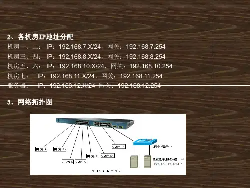
配置思科三层交换的综合案例网络基本情况网络拓扑结构为:中心交换机采用Cisco Catalyst 4006-S3,Supervisor Engine III G引擎位于第1插槽,用于实现三层交换;1块24口1000Base-T模块位于第2插槽,用于连接网络服务器;1块6端口1000Base-X模块位于第3插槽,用于连接6台骨干交换机。
一台交换机采用Cisco Catalyst 3550-24-EMI,并安装1块1000Base-X GBIC千兆模块。
一台交换机采用Cisco Catalyst 3550-24-SMI,也安装1块1000Base-X GBIC千兆模块。
另外四台交换机采用Cisco Catalyst 2950G-24-SMI,安装1块1000Base-T GBIC千兆模块。
所有服务器划分为一个VLAN,即VLAN 50。
四台Catalyst 2950G-24-SMI交换机也只划分为一个VLAN,分别为VLAN 60、VLAN 70、VLAN 80和VLAN 90。
Catalyst 3550-24-EMI划分为4个VLAN,分别为VLAN 10、VLAN 20、VLAN 30和VLAN 40。
Catalyst 3550-24-SMI划分2个VLAN,分别为VLAN 60和VLAN 80,与另外两台Catalyst 2950G-24-SMI交换机分别位于同一VLAN。
***************************实例分析****************************由于所有Catalyst 2950G交换机都是一个独立的VLAN,因此,必须先在这些交换机上创建VLAN(VLAN 60~VLAN 90),并将所有端口都指定至该VLAN。
然后,再在Catalyst 4006交换机相应端口上分别创建VLAN。
Catalyst 4006的1000Base-X端口分别与各Catalyst 2950G的1000Base-X端口连接。
使用带 WEP 加密和 LEAP 认证的 ISR 连接无线局域网配置示例目录简介先决条件要求使用的组件网络图规则871W路由器配置客户端适配器配置验证故障排除相关信息简介本文档介绍如何配置Cisco 870系列集成多业务路由器(ISR),以便通过WEP加密和LEAP身份验证实现无线LAN连接。
同样的配置适用于任何其他Cisco ISR无线系列型号。
先决条件要求尝试进行此配置之前,请确保满足以下要求:了解如何配置Cisco 870系列ISR的基本参数。
q了解如何使用Aironet桌面实用程序(ADU)配置802.11a/b/g无线客户端适配器。
q有关如何配置802.11a/b/g客户端适配器的信息,请参阅Cisco Aironet 802.11a/b/g无线LAN客户端适配器(CB21AG和PI21AG)安装和配置指南,版本2.5。
使用的组件本文档中的信息基于以下软件和硬件版本:运行Cisco IOS®软件版本12.3(8)YI1的Cisco 871W ISRq带Aironet桌面实用程序2.5版的笔记本电脑q运行固件版本2.5的802.11 a/b/g客户端适配器q本文档中的信息都是基于特定实验室环境中的设备编写的。
本文档中使用的所有设备最初均采用原始(默认)配置。
如果您使用的是真实网络,请确保您已经了解所有命令的潜在影响。
网络图本文档使用此网络设置。
在此设置中,无线LAN客户端与870路由器关联。
870路由器上的内部动态主机配置协议(DHCP)服务器用于为无线客户端提供IP地址。
在870 ISR和WLAN客户端上启用WEP加密。
LEAP身份验证用于验证无线用户,870路由器上的本地RADIUS服务器功能用于验证凭证。
规则有关文档规则的详细信息,请参阅 Cisco 技术提示规则。
871W路由器配置完成以下步骤,将871W ISR配置为接入点,以接受来自无线客户端的关联请求。
配置集成路由和桥接(IRB)并设置网桥组。
交换机路由器配置:Cisco组网实例2011-08-16 21:5251CTO51CTO
字号:A+|A-一、Cisco 2950交换机基本配置
switch>
switch>enable
switch#
switch#vlan database(进入vlan维护模式)
switch(vlan)#vlan 2 name vlan2(给vlan 2命名为vlan2)
switch(vlan)#vlan 4 name vlan4(给vlan 4命名为vlan4)
switch(vlan)#exit(这里要注意一下,要打入exit退出才有效,不能用ctrl+z或end直接退出,因为这么不能使配置生效!)
switch#show vlan(查看vlan的配置,默认有vlan1)
switch#configure terminal(进入全局配置模式)
switch(config)#interface f0/1(进入fastethernet0/1接口配置模式)
switch(config-if)#switchport mode access(这步可以省略)
switch(config-if)#switchport access vlan 2(把该接口划分到vlan2,记得vlan2之间有空格)
switch(config-if)#no shutdown(激活端口)
switch(config-if)#exit
switch(config)#interface f0/2
switch(config-if)#switchport mode access
switch(config-if)#switchport access vlan 4
switch(config-if)#no shutdown
switch(config-if)#exit
switch(config)#interface f0/3
switch(config-if)#switchport mode trunk(设置此口为中继模式)
switch(config-if)#no shutdown
witch(config-if)#exit(这里可以直接用ctrl+z或end直接退出到特权模式)
二.在路由器Cisco 2611上的配置(单臂路由)
router#configure terminal
router(config)#interface f0/0.1(进入子接口模式)
router(config-subif)#encapsulation dot1q 2(设置封装类型为dot1q,它是思科特有的。
此外还有isl封装,要看该设备支不支持。
数字2是vlan号)
router(config-subif)#ip address 192.168.1.1 255.255.255.0
router(config-subif)#exit
router(config)#interface f0/0.2
router(config-subif)#encapsulation dot1q 4
router(config-subif)#ip address 192.168.3.1 255.255.255.0
router(config-subif)#exit
router(config)#interface f0/0
router(config-if)#no shutdown
router(config-if)#^z
router#show running-config
router#copy running-config startup-config
三.给PC1,PC2设置好IP地址,然后用ping命名令测试!
1、配置IP地址
交换机要能够被网管,必须给它标识一个管理IP地址,默认情况下CISCO交换机的VLAN 1为管理VLAN,为该VLAN配上IP 地址,交换机就可以被网管了。
命令如下:
a、进入全局模式: Switch#configure terminal
b、进入VLAN 1接口模式:Switch(config)#interface vlan 1
c、配置管理IP地址:Switch(config-if) # ip address [A.B.C.D] [mask]
如果当前VLAN 不是管理VLAN ,只需要将上面第b处命令的vlan的号码换成管理VLAN的号码即可。
2、打开SNMP协议
a、进入全局模式: Switch#configure terminal
b、配置只读的Community,产品默认的只读Community名为public
Switch(config)#snmp-server community public ro
c、配置可写的Community,产品默认的可写Community名为private
Switch(config)#snmp-server community private rw
3、更改SNMP的Community密码
a、将设备分组,并使能支持的各种SNMP版本
Switch(config)#snmp-server group qycx123 v1
Switch(config)#snmp-server group qycx 123 v2c
Switch(config)#snmp-server group qycx123 v3 noauth
b、分别配置只读和可写community 如:
Switch(config)#snmp-server community qycx123 ro
Switch(config)#snmp-server community qycx123 rw
4、保存交换机配置
Switch#copy run start
交换机配置的常用命令读者如果不明白可以阅读:思科交换机常用命令总结
原文出自【比特网】,转载请保留原文链接:/61/12139561.shtml。