A Wireless and Context-Aware ECG MonitorAn iMote2 Based Portable system
- 格式:pdf
- 大小:141.86 KB
- 文档页数:4

神经网络算法与无线传感器网络的关联研究无线传感器网络(Wireless Sensor Networks, WSN)是一种通过大量的分布在空间中的传感器节点收集、处理和传输数据的网络系统。
神经网络算法(Neural Network Algorithm)是一种模仿人类神经系统工作方式的计算模型,能够通过学习和训练来识别和预测模式。
这篇文章将探讨神经网络算法与无线传感器网络之间的关联研究。
首先,我们将介绍无线传感器网络的基本原理和神经网络算法的基本概念,然后讨论两者的结合应用以及研究中存在的挑战和解决方法。
无线传感器网络的关键组成部分是传感器节点,它们能够感知和采集周围环境的物理量。
传感器节点通常包含有限的计算和存储能力,因此需要一种高效的算法来处理数据。
神经网络算法是一种非常有效的数据处理方法,它能够学习和预测模式、优化决策和适应环境变化。
神经网络算法在无线传感器网络中的应用可以包括以下几个方面。
首先,神经网络算法可以用于传感器节点的负载均衡,通过数据预测和分析来选择节点上的任务分配,以实现资源的有效利用。
这可以减少能耗和延迟,并提高网络的性能。
其次,神经网络算法可以用于无线传感器网络中的数据压缩和聚合。
传感器节点通常会产生大量的数据,这些数据需要通过有限的网络带宽传输到中心节点进行处理和存储。
利用神经网络算法可以对数据进行压缩和聚合,减少数据的传输量,提高网络的效率。
此外,神经网络算法还可以用于无线传感器网络中的能量管理和优化。
由于传感器节点通常是由有限电池供电,能量管理是一个重要的问题。
神经网络算法可以通过学习和预测能量消耗模式,为节点提供能量管理策略,延长网络的寿命。
然而,在将神经网络算法与无线传感器网络结合应用时,也存在一些挑战和问题需要解决。
首先,传感器节点的计算和存储能力有限,因此需要设计轻量级的神经网络模型,以适应节点的硬件限制。
其次,传感器网络中的数据通常具有时空相关性,需要考虑这种相关性对神经网络算法的影响。

上海交通大学附属中学2022-2023学年度第二学期高二英语摸底考试试卷(满分150分,120分钟完成。
答案请写在答题纸上。
)命题:张宁审核:程姑第I卷II. Grammar and Vocabulary (20'+20‘)Section ADirections: Beneath each of the following sentences there are four choices marked A,B, C and D. Choose the one answer that best completes the sentence.21.These teenage girls prefer to take pictures________ stands a famous cubism painting in a gallery.A. whereB. whatC. whenD. as22.When guided to reflect on their good fortune, people tend to be more thankful for and appreciative of ________ they have and ________ they are on their path right now, thus more willing to contribute to the common good.A. which, whenB. what, whereC. all, whichD. all, that23.-The wounded soldier ________ have been sent to hospital immediately.-So he ________ , but all efforts made no difference.A. should, wasB. must, didC. ought to, hadD. can, has24.With robots coming to the rescue and appearing on the farm scene, farming has been more efficient with regard to the time ________takes to inspect crops and dig up weed.A. whatB. itC. oneD. which25.We need________ to have a good command of English as a medical student needs ________a doctor.A. as long and tough a training, to becomeB. as long and tough a training, becomingC. as a long and tough training, to becomeD. as a long and tough training, becoming26.The success of Full River Red (Man jiang hong), a 2023 historical suspense comedy film directed by Zhang Yimou, is such________ even some western celebrities have started to read Chinese history.A. asB. likeC. thatD. making27.According to economics, money flows to ________ it is that controls the scarce thing, say, the cutting-edge knowledge.A. whomB. whomeverC. whoD. whoever28.It is natural that the prominent actress ________ charged with tax evasion.A. wereB. would have beenC. may have beenD. should have been29.Premier Li Keqiang is going to take questions from both Chinese and foreign correspondents at the annual press conference_________ in March.A. to holdB. to take placeC. occurredD. held30.Given the serious damage and substantial losses caused by the recent 7.8 magnitude earthquakewhich struck southern Turkey, just 50 miles from the Syrian border, more financial support from international society _________.A. remaining to be raisedB. remains to be raisedC. remaining to raiseD. remains to raise31.The firm has been taking measures to cut costs to keep its _________up, including purchasing cheaper raw materials and reducing its workforce.A. expenditureB. profitsC. salariesD. rank32.The idle afternoon we are going through at home really deserves a fix of coffee or tea to _________our tired minds.A. repairB. refreshC. recoverD. rescue33.General Motors(GM) plans to _________ its two plants to electric vehicle production by 2035 and another plant in Coahuila will make the new model of Chevrolet Blazer from 2024.A. converseB. convertC. conserveD. preserve34.Since the second wave of COVID-19 pandemic in China, investors from home and abroad have lowered expectations of these tech companies, making it harder to lift their _________.A. marketsB. pricesC. brandsD. shares35.A record 3.3 million Americans applied for unemployment _________in the third week of March 2020, according to the US Labor Department, as restaurants, hotels, barber shops, gyms and more shut down in a nationwide effort to slow the spread of the deadly coronavirus.A. claimsB. benefitsC. interestsD. objectives36.On hearing the heart-breaking news, she couldn't _________herself and broke out crying.A. regainB. reserveC. composeD. comprise37.ALK or the gene for anaplastic lymphoma kinase is a stretch of DNA whose mutant (突变的)form has been associated with human cancers, but, its normal function which has something to do with thinness in humans had not been _________before the research.A. foundedB. establishedC. maintainedD. received38.When the candidate presented the results of his experiment on the brain of mice to the pharmaceutical company, they laughed and paid no _________to the discovery which later turned out to be a brilliant idea for a new product.A. investigationB. regardC. noticeD. inspection39.In the 4-day Shanghai Disneyland Tour, you will spend a full day venturing in dream-like Disney castle, gardens, _________ film scenes, enjoying fabulous kid joy with famous Disney characters and various family entertainment activities and amusing shows.A. fancyB. fantasyC. fascinationD. fashion40.The policy _________ "renationalisation”, and throws the country's financial markets back to the past, complains the economist shepherding privatization for the former prime minister.A. accumulatesB. amounts toC. equals toD. recovers Section B:Directions: Complete the following passages by using the words in the box. Each word can only be used once. Note that there is one word more than you need.(A)A. selectedB. distinctiveC. signatureD. odds AB. domestication AC. decidedAD. individuals BC. tamest BD. conflicted CD. mixed ABC. developIf you see a house cat, the_____41_____are high that it will have white paws, a look that many owners affectionately call“socks." But socks are rarely seen in wildcats, the elusive and undomesticated cousin of the house cat, so why do so many pet cats sport furry white feet?As it turns out, this story started about 10,000 years ago, when humans and cats _____42 _____ life was better together.This_____43 _____eventually led to uber-prevalent socks on cats, as well as other well-known coat patterns, said Leslie Lyons, professor emerita and head of the Feline Genetics Laboratory at the University of Missouri College of V eterinary Medicine.“As humans became farmers and started staying in one place, they had grain stores and waste piles” that attracted rodents, Lyons said. It was a mutually beneficial arrangement: the humans had fewer rodents to deal with and the cats got an easy meal.The wild, undomesticated ancestor species of house cats, Felis silvestris, lives in Africa and Eurasia. These felines are tasty snacks as kittens and stealthy predators as adults, so _____44 _____ born with a coat that offers camouflage (保护色)have tended to survive and reproduce.But not every F. silvestiis is born with a coat that blends into its habitat."Genetic mutations are occurring all the time.” Lyons said.There isn't much evidence to indicate why early cat people chose the individuals they did, but Lyons said the range of coats seen on modern domestic cats shows that our agrarian ancestors favored cats with markings that would have _____45 _____with their camouflage.In its native mixed forest or scrub desert environment, a cat with stark white paws would have stood out to predators and prey.When humans started taking an interest in cats, these white paws would have stood out to them, too. “There were probably people saying,‘I particularly like that kitten because it has white feet . Let's make sure it survives, Lyons said.Humans probably also_____46 _____cats who were calm and comfortable around humans, Lyons said. Behavioral traits seem unrelated to coat color, but for reasons that scientists don't fully understand, white spots tend to appear when the _____47 _____individuals are selected and bred.These_____48_____fur colors and markings emerge while a cat embryo is developing. The cells that give cat fur its color first appear as neural crest cells, which are located along what will become the back, Lyons said.Then, those cells slowly migrate down and around the body. If those waves of cells move farenough to meet each other on the cat's front side, the embryo will be born a solid-colored kitten, such as an all-black or all-orange cat. Felines _____49 _____white feet, faces, chests and bellies when these cells don't quite make it all the way.So, the next time you see a kitty wearing white socks, you'll know that this _____50 _____ feature is a result of genetic mutations, domestication and developmental biology. Although if you try telling the cat that, it will probably just look at you quizzically before sauntering away.(B)A. initiallyB. formedC. societiesD. map AB. officiallyAC. constructed AD. potentially BC. investigate BD. perspective. CD. boundaries ABC. considerationConstruction of the world's largest radio astronomy observatory, the Square Kilometre Array, has_____51_____begun in Australia after three decades in development.A huge intergovernmental effort, the SKA has been hailed as one of the biggest scientific projects of this century. It will enable scientists to look back to early in the history of the universe when the first stars and galaxies were _____52_____.It will also be used to _____53 _____dark energy and why the universe is expanding, and to _____54 _____search for extraterrestrial life.The SKA will _____55_____ involve two telescope arrays---one on Wajarri country in remote Western Australia, called SKA-Low, comprising 131,072 tree-like antennas. SKA-Low is so named for its sensitivity to low-frequency radio signals. It will be eight times as sensitive than existing comparable telescopes and will _____56 _____the sky 135 times faster.A second array of 197 traditional dishes, SKA-Mid, will be built in South Africa's Karoo region.Dr Sarah Pearce, SKA-Low's director, said the observatory would "define the next fifty years for radio astronomy, charting the birth and death of galaxies, searching for new types of gravitational waves and expanding the_____ 57 _____of what we know about the universe'1.She added: "The SKA telescopes will be sensitive enough to detect an airport radar on a planet circling a star tens of light years away, so may even answer the biggest question of all: are we alone in the universe?"The SKA has been described by scientists as a gamechanger and a major milestone in astronomy research."To put the sensitivity of the SKA into _____58 _____, it could detect a mobile phone in the pocket of an astronaut on Mars, 225m kilometres away,” said Dr Danny Price, a senior postdoctoral fellow at the Curtin Institute of Radio Astronomy." More excitingly, if there are intelligent _____59 _____ on nearby stars with technology similar to ours, the SKA could detect the aggregate 'leakage' radiation from their radio and telecommunication networks~the first telescope sensitive enough to achieve this feat."Prof Alan Duffy, director of the space technology and industry institute at the Swinburne University of Technology, said the SKA would probably be the largest telescope _____60 , _____,"connecting across continents to create a world-spanning facility allowing us to see essentially across the entire observable universe".III. Reading Comprehension (15'+22'+8‘)Section ADirections: For each blank in the following passage there are four words or phrases marked A, B, C and D. Fill in each blank with the word or phrase that best fits the context.The economic case for regiftingDespite its pleasures, gift giving can be problematic.A recipient wants items A andB (say, a hat and gloves) yet receives itemsC andD (say, a scarf and mittens). Another recipient wants C and D, yet receives A and B. The_____ 61 _____ seems simple: The two recipients can simply pass along the gifts they received to each other.The _____62_____ however, is more complex. People in a study published in the Journal of Consumer Behaviour, for instance, used such words as guilty, lazy, thoughtless and disrespectful in describing their_____63 _____ about regifting. Popular culture casts it as taboo, as well.Getting stuck with gifts we do not want is no small problem. Consider that the National Retail Federation calculated that the average holiday-season______64 _____in the U.S. last year spent more than $1,000 on gifts. In a survey across 14 countries in Europe, meanwhile, 1 in 7 said they were unhappy with what they received for Christmas, yet more than half simply kept the gifts.Why can't more gifts be passed along to people who _____65 _____them?Our research with Francis J. Flynn, a professor of organizational behavior at Stanford University's Graduate School of Business, suggests the shame associated with regifting is largely _____66 _____. Indeed, our research consistently tells us that people overestimate the negative consequences.We conducted a study in which we asked people to imagine themselves either as a "giver,” who gives someone a gift card and later _____67_____it has been regifted; or as a "regifter," one who receives the gift and gives it to someone else. The latter group saw more offense. Regifters tended to assume the original givers would be _____68_____ when they found out. The general _____69_____ of the original givers, however, was: It's your gift, do what you want with it.”Next, we tried to shed light on just how serious the perceived offense is. We asked two group —again givers and regifters—to______70_____ regifting a hypothetical (假设的)wristwatch with throwing it in the trash. For the original givers, regifting the watch was a much less offensive act than trashing it. The regifters, however, _____71 _____ assumed that the givers would find both equally offensive.Finally, given that the feared offense looks more imagined than real, we turned our attention to how people might be_____72_____ to break this taboo.For this part of our research, we invited to our lab at Stanford people who had recently received presents and divided the people into two groups. When we gave the first group an opportunity to_____73_____that present, 9% did so.When we gave the second group the same opportunity, we added that it was '"National Regifting Day,” a real______74 _____that happens each year on the Thursday before Christmas. It wasn't really National Regifting Day, but the group didn't know that: 30% of them agreed to regift.Everyone has received bad gifts in their lives, and we generally accept that we will receive more in the future. Yet for some reason, we believe that we give only good gifts.Our research offers a simple solution to the problem of _____75 _____ gifts. This holiday season, consider regifting, and encourage people who receive your gifts to do the same if what you give them isn't quite what they hope for.61.A. result B. cycle. C. trick D. solution62.A. cause B. psychology C. science. D. theory63.A. feelings B. ideas C. trick. D. evaluations64. A. citizen B. retailer C. shopper D. foreigner65. A. refuse B. appreciate C. envy D. collect66. A. perceived B. ignored C. unjustified D. immeasurable67. A. learns B. suspects C. complains D. imagines68. A. praised B. hurt C. hateful D. grateful69. A. motto B. code C. principle D. attitude70. A. replace B. connect C. compare D. exchange71. A. desperately B. voluntarily C. responsibly D. wrongly72. A. encouraged B. pushed C. challenged D. forced73.A. hide B. sell C. regift D. decline74. A. ceremony B. celebration C. day D. event75. A. unpopular B. unwanted C. expensive D. meaninglessSection BDirections: Read the following three passages. Each passage is followed by several questions or unfinished statements. For each of them there are four choices marked A, B, C and D. Choose the one that fits best according to the information given in the passage you have just read.(A)Jailbreaking commonly refers to unlocking iOS for iPhones and iPads. Seventeen-year-old George Hotz, or geohot as he liked to be called, was the first person to jailbreak an iPhone. He accomplished his feat in 2007, and many others followed his lead.Jailbreaking an iPhone offers some distinct benefits. With a jailbroken iPhone, you have numerous ways to change any setting to suit your needs. You can also alter the look and feel of the phone so that it matches your personality. Another advantage of jailbreaking for iPhone users is the ability to install apps not offered in Apple's App Store. Cydia, an alternative app store for jailbroken iOS devices, offers a variety of apps, some of which cost more than others.Before jailbreaking your iPhone, you should consider the consequences. Jailbreakingimmediately voids (使无效)your iPhone's warranty, which means that Apple is no longer required to fix your phone if something goes wrong. Jailbreaking also exposes you to the dangers associated with alternative apps. Poor quality apps from alternative app stores may cause your iPhone to crash more often or stop working altogether. After jailbreaking your iPhone, you must also be careful not to allow Apple to install new software on your phone.Apple naturally discourages its customers from jailbreaking their iPhones. According to the company, jailbreaking doesn't just affect the security and stability of an iPhone. It can also shorten the phone's battery life. For many people, this is an important consideration.76. Which aspects of jailbreaking does the article discuss?A. The ways in which jailbreaking can save people timeB. The positives and negatives associated with jailbreakingC. The clients who got into legal trouble for jailbreakingD. The best and worst techniques for jailbreaking phones77.What does the article imply about the first person to jailbreak an iPhone?A. He apologized for his actions.B. He produced hardware designs.C. He gave himself a nickname.D. He was turned down for a job.78.From this article, what can readers learn about the products offered by Cydia?A. Their prices vary somewhat.B. Their inventors are quite young.C. They're still manufactured abroad.D. They take only a few moments to install.79.According to Apple, what might happen after a person jailbreaks his or her iPhone?A. It might need a new camera stand.B. It might become harder to sell.C. It might be easily damaged by water.D. It might use up its battery faster.(B)Vanuatu is an island nation in the South Pacific. It is also one of the smallest countries in the world. But for those interested in adventure and sport, there is a lot to do. Some of the best snorkeling (浮湖) can be found here. Vanuatu's islands also offer visitors two of the most exciting and dangerous activities in the world: volcano surfing and land diving.Volcano SurfingOn Tanna Island, Mount Yasur rises 300 meters (1,000 feet) into the sky. It is known as the Lighthouse of the Pacific because of its regular eruptions for hundreds of years. For centuries, both island locals and visitors have climbed this mountain to visit the top. Some visitors find Yasur terrifying; others cautivating. Photographers are beside themselves at the opportunity to make stunning artwork from such a special point. Recently, people have also started climbing Yasur to surf the volcano.In some ways, volcano surfing, also commonly known as ash boarding, is like surfing in the sea, but in other ways it’s very different. It was invented by an adventurer journalist named Zoltan Istvan, while on a trip to Vanuatu Islands in 2002. V olcano surfing is considered as an extreme sport and there are not many practicing it. A volcano surfer's goal is to escape the erupting volcanowithout getting hit by flying rocks! Riders hike up the volcano and slide down, sitting or standing, on a thin plywood or metal board. It's fast, fun, and dangerous—the perfect extreme sport.Land DivingMost people are familiar with bungee jumping, but did you know bungee jumping started on Pentecost Island in Vanuatu and is almost fifteen centuries old? The original activity, called land diving, is part of a religious ceremony. A man ties tree vines (藤) to his legs. He then jumps headfirst from a high tower. It originated as a rite (仪式) of passage for young men trying to prove their manhood. The idea is to jump from as high as possible, and to land as close to the ground as possible. It is also a harvest ritual. The islanders believe the higher the jumpers dive, the higher the crops will grow. Every spring, island natives (men only) still perform this amazing test of strength.80.Which of the following can be learned from the passage?A. Mount Yasur is a light tower on the Pacific Ocean.B. The history of volcano surfing dates back centuries.C. Bungee jumping grew out of land diving.D. Land diving came to Vanuatu from another country.81.The underlined word captivating is closest in meaning to _______.A. distressingB. charmingC. disappointingD. relieving82.Which of the following could be the best title of this passage?A. Untouched Beauty: V ANUA TUB. V olcano Adventure: V ANUATUC. Extreme Destination: V ANUA TUD. Preserved Culture: V ANUATU(C)The water off the coast of northwest Greenland is a glass-like calm, but the puddles (水坑)on the region's icebergs are a sign that a transformation is underway higher on the ice sheet.Several days of unusually warm weather in northern Greenland have caused rapid melting, made visible by the rivers of meltwater rushing into the ocean. Temperatures have been running around 60 degrees Fahrenheit—10 degrees warmer than normal for this time of year, scientists said.The amount of ice that melted in Greenland between July 15 and 17 this year alone—6 billion tons of water per day~~would be enough to fill 7.2 million Olympic-sized swimming pools, according to data from the US National Snow and Ice Data Center,Each summer, scientists worry that they will see a repeat of the record melting that occurred in 2019, when 532 billion tons of ice flowed out into the sea. An unexpectedly hot spring and a July heat wave that year caused almost the entire ice sheet's surface to melt. Global sea level rose permanently by 1.5 millimeters as a result.Greenland holds enough ice一if it all melted一to lift sea level by 7.5 meters around the world. The latest research points to a more and more threatening situation on the Northern Hemisphere'siciest island.“Unprecedented" rates of melting have been observed at the bottom of the Greenland ice sheet, a study published in February found, caused by huge quantities of meltwater flowing down from the surface. This water is particularly concerning because it can destabilize the sheet above it and could lead to a massive, rapid loss of ice.And in 2020, scientists found that Greenland's ice sheet had melted beyond the point of no return. The rate of melting in recent years exceeds anything Greenland has experienced in the last 12,000 years, another study found—and enough to cause measurable change in the gravitational field over Greenland.At the East Greenland Ice-core Project~ or EastGRIP—research camp in northwest Greenland, the work of scientists to understand the impact of climate change is being affected by climate change itselfAslak Grinsted, a climate scientist at the University of Copenhagen's Niels Bohr Institute, said that they have been trying to get flights into the camp but the warmth is destabilizing the landing site.Before human-caused climate change kicked in, temperatures near 32 degrees Fahrenheit there were unheard of. But since the 1980s, this region has warmed by around 1.5 degrees Fahrenheit per decade—four times faster than the global pace—making it all the more likely that temperatures will cross the melting point.83.The passage is mainly written to _______.A. alert people to the rapid melting of Greenland's ice sheetB. arouse people's awareness of protecting the environment of GreenlandC. inform people of the large amount of ice Greenland holdsD. reveal to people the cause and effect of the rise in sea level84.What does "a transformation” in the first paragraph refer to?A. Climate change.B. A rise in sea level.C. Global warming.D. The melting of ice.85.What can be learned about the ice that melted in 2019?A. It repeated a record melting of the ice sheet several years ago.B. Its amount was the largest ever and lifted sea level permanently.C. It was enough to fill 7.2 million Olympic-sized swimming pools.D. Its melting rate was so rapid as to result in an unexpectedly hot spring.86.It is implied in the passage that _______.A. climate change is a result of human activitiesB. the study of climate change is being made easierC. the melting of Greenland's ice sheet is reversibleD. temperatures increase 1.5°F or so each decade globallySection CDirections: Read the following passage. Fill in each blank with a proper sentence given in the box. Each sentence can be used only once. Note that there are two more sentences than you need.A. They also found cetaceans gained and lost TSGs at a rate 2.4 times higher than in other mammals.B. If the whale gene was injected into the human body, could humans fight cancer?C. Some people deny that cetaceans can increase TSGs faster than other mammals.D. If you have more cells that means that one of those cells has an increased risk of becoming cancerous.AB.In contrast, cetaceans have much lower cancer rates than most other mammals.AC.But we still need to learn more about why and how they did this.Can Whales And Dolphins Fight Cancer?Whales and dolphins have been shown to be better at fighting cancer than we are, and now we may be closer to understanding why cetaceans (鲸目动物)do it. Cetaceans are generally the oldest living mammals, and some cetaceans have reached their 200th birthday. Their size means their bodies contain far more cells than the human body."_______87_______” says Daniela Tejada-Martinez at the Austral University of Chile. “So, if you are big or live longer, you have thousands and millions of cells that could become harmful." _______88_______“There's a joke that whales should be born with cancer and not even able to exist because they're just too big,” says Vincent Lynch at the University at Buffalo, New York, he says there is a super trivial explanation for how whales can exist. "They just evolved better cancer protection mechanisms," he says. ______89 _______Now, Tejada-Martinez and her colleagues have studied the evolution of 1077 tumor suppressor (肿瘤抑制)genes (TSGs). In all, they compared the evolution of the genes in 15 mammalian species, including seven cetacean species, Genes regulating DNA damage, tumor spread and the immune system were positively selected among the cetaceans. _______90 _______“It's not like we're gonna be taking whale genes and putting them into humans and making humans cancer resistant,” says Lynch. "But if you can find the genes that play a role in tumor suppression in other animals, and if you can figure out what they're doing, maybe you can make a drug that can be used to treat people."第II卷IV Grammar (10+10)Directions: After reading the passages below, fill in the blanks to make the passages coherent and grammatically correct For the blanks with a given word, fill in each blank with the proper farm of the given word; far the other blanks, use one word that best fits each blank.(A)When Steve Birkinshaw, the British fell running (越野路跑)champion, planned his record-。
用菲涅尔区模型探究WiFi 感知系统的稳定性牛凯1,2,张扶桑3,吴丹1,2,张大庆1,2+1.北京大学信息科学技术学院高可信软件技术教育部重点实验室,北京1008712.北京大学(天津滨海)新一代信息技术研究院,天津3004503.中国科学院软件研究所计算机科学国家重点实验室,北京100190+通信作者E-mail:*************** 摘要:基于WiFi 的非接触感知系统利用环境中广泛存在的WiFi 信号在自然情况下对用户活动进行感知,具有十分广阔的应用前景。
从细粒度活动到粗粒度活动,现有工作进行了大量的探索,但尚未理解和解决感知系统稳定性不足的问题。
当感知对象、收发设备位置、测试环境等发生变化时,系统性能会受到严重影响。
实际上,人体活动对应的接收信号模式因位置和朝向的变化而带来的不一致性导致了系统不能稳定工作。
为了理解这种现象的本质,利用团队提出的基于无线感知的菲涅尔区衍射和反射模型,精确定量刻画了目标物体相对于收发设备的位置、运动轨迹和无线信号波形模式之间的关系。
通过两个应用实例,即细粒度的手指动作识别和粗粒度的健身活动识别,在模型的指导下,分别解释了系统不能稳定工作的原因,说明了如何得到一致的感知波形,以及如何构造可区分的感知波形,并给出了提升感知系统性能的方法。
关键词:菲涅尔区模型;系统稳定性;WiFi ;无接触感知文献标志码:A中图分类号:TP399Exploring Stability in WiFi Sensing System Based on Fresnel Zone ModelNIU Kai 1,2,ZHANG Fusang 3,WU Dan 1,2,ZHANG Daqing 1,2+1.Key Laboratory of High Confidence Software Technologies,Ministry of Education,School of Electronics Engineering and Computer Science,Peking University,Beijing 100871,China2.Peking University Information Technology Institute (Tianjin Binhai),Tianjin 300450,China3.State Key Laboratory of Computer Sciences,Institute of Software,Chinese Academy of Sciences,Beijing 100190,China Abstract:WiFi based contactless sensing systems use pervasive wireless communication signals in the environment to sense human activities in a natural way,enabling many promising applications.From fine-grained activity sensing to coarse-grained activity recognition,existing work have done a great deal of exploration.However,there is lack of understanding and tackling the serious unstable sensing performance problem.While changing the human target,the position of transceivers,and test environment,the system performance is severely degraded.The reason behind the instability of WiFi-based sensing system is that human activities induce the inconsistent signal patterns inherently at different positions.This paper proposes the Fresnel zone-based diffraction and reflection sensing model,which can计算机科学与探索1673-9418/2021/15(01)-0060-13doi:10.3778/j.issn.1673-9418.1912017基金项目:国家自然科学基金(61572048,61802373);北大百度基金资助项目(2019BD005);中国科学院青年创新促进会项目(2020109)。

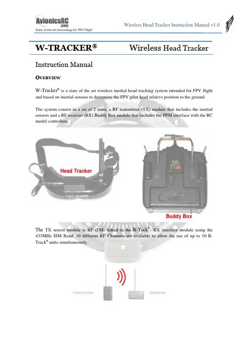
W-TRACKER ®Wireless Head TrackerInstruction ManualOVE R V IEWW-Tracker R is a state of the art wireless inertial head tracking system intended for FPV flightand based on inertial sensors to determine the FPV pilot head relative position to the ground.The system consist in a set of 2 units, a RF transmitter (TX) module that includes the inertial sensors and a RF receiver (RX) Buddy Box module that includes the PPM interface with the RC model controllers.The TX sensor module is RF (FM) linked to the R-Tack R RX interface module using the 433MHz ISM Band. 10 different RF Channels are available to allow the use of up to 10 R-Track R units simultaneously.Transmitter Head Tracker Buddy Box ReceiverR-Tack R includes 3 cables:1.- Head Tracker supply cable.2.- Futaba connector for stand – alone use3.- Futaba connector for master – slave use.W-Tracker R is designed to be used with a single transmitter, or between a trainer transmitter,and a student transmitter. When used in Master - Slave mode, The student Tx is supplied through the W-Tracker R .The connectors on the W-Tracker Rmodules are standard 3.5mm 4pin jack receptacles in order to make the system compatible with several radio models. See annex for pin-out reference.W-Tracker R is shipped with a power supply cable compatible with the Fatshark RCV922 headset battery connector. For other FPV headsets, please check annex to adapt or build thepower supply cable. Same happens with the transmitter connectors, R-Tack Ris shipped with Futaba connectors, but connectors as WFLY and others can be used, please check annex to adapt or build the transmitter cables.H E A D T R A C K E R M O D U L EThe Head tracker module includes the inertial sensors, and a 433MHz micro FM transmitter.In the top of the HT there is a bicolour movement indicator light and a pushbutton for configuration purposes.In the Bottom Side there is a rotary switch to select the radio channel to be used. It is possible to use up to 10 W-Tracker R simultaneously. You should select the same channel in the Head Tracker module and in the buddy box module.There is a 4 pin 3.5mm jack receptacle in the right side of the HT that supplies the HT unit with the same 2S Li-Po battery that supplies the FPV headset.Battery Output Activity LEDConfigurationPush-ButtonIt is recommended to use a velcro-type adhesive tape to mount the Head Tracker on the FPV headset.The battery power connectors are connected in parallel, so once connected to the battery they are supplying power to the Head Tracker. This is important because if you are not using the Head Tracker it is recommended to disconnect the battery from the power supply connector to avoid a complete discharge of the headset battery.Before fixing the Head Tracker on the headset, you should set the HT channel frequency. Use the same plastic screwdriver used for the channel frequency selection in the RC transmitter.Once selected the channel you can mount the Head Tracker on the FPV headset.Battery Input Channel Select Rotary Switch512 34 6 9 8 7Adjusting SensitivityThe horizontal movement sensitivity can be set with the Push Button. The W-Tracker R allows 3 sensitivity modes: High, Medium and Low. Sensitivity affects to the motion threshold detection.W-Tracker R determines horizontal position only when you move your head, so if you are moving continuously the HT, there will be a cumulative error position. In the highest sensitivity mode, even a very slow movement will be detected by the HT, so the probability to experiment error position will be higher, in the other side, the movement is detected instantaneously. By lowering the sensitivity you will have less error position.By pushing continuously the push button, the HT will show you first a red light (High Sensitivity), after a green light (Medium Sensitivity) and finally an orange light (Low Sensitivity). By releasing the push button when the light is in the desired colour, you will set the sensitivity.Cold StartWhen HT starts it determines the “zero position” and during this process it is mandatory to keep still the HT. Once determined the “zero position”, the green light will blink during 2 minutes (approx) what means the HT is performing temperature compensation.If during starting process the Red Led is continuously blinking, it means that it cannot determine the zero position, so you should disconnect the unit from the battery and reconnect after 3 seconds again.OffsetSystem is designed to cancel the horizontal drift, but in exceptional cases, if you observe any drift, just stop completely your head and wait until the servo motion stops, after that any drift will disappear.If during the use of the HT you experiment any offset position (due to the cumulative errors), you can compensate it by moving your head to the operation limit side of the deviation; by exceeding the HT detection limit you will set a new offset (opposite to the original) to the movement that will cancel the original offset.zero Right Limit Left Limit Working normally (without offset)In both cases, the HT takes the last position (beyond the limit) as the new limit, and allows the user the offset correction.B U D D Y B O X M O D U L EThe Buddy Box module has 2 x 3.5mm 4 PIN jack receptacles ‘A’ and ‘B’ as follows:There are also 2 connectors for the RC transmitters:Left offset correction by moving your head beyond the Left limit Right Limit Right offset correction by moving your head beyond the Right limitoffsetA BCable for Master RC Transmitter(teacher)Cable for Slave RC Transmitter(student)SHORT CABLE LONG CABLEThe Buddy Box works generating or reading PPM streams from the RC transmitters. It reads PPM signals from receptacle B and transmits PPM signals trough receptacles A and B.Buddy Box working modes are:• “PPM GEN” Stand Alone ModeIn this mode the Buddy Box generates a PPM data stream like a student RC transmitter; when the trainer function is activated on the RC transmitter, the channels associated to the Pan & Tilt motion will be activated.This mode can only be used if your TX has the option to disable the trainer channels not used for the Pan & Tilt Function.This mode is typically used when the RC system is working in PCM Mode and the student RC transmitter is not connected, although it can be also used in PPM mode.You should use the short cable to connect the RC transmitter to the Buddy Box receptacle A or B (it doesn’t matter).• “PPM FeedBack” Stand Alone ModeIn this mode the Buddy Box reads the PPM data stream from your RC transmitter and inserts the Pan & Tilt information on the PPM stream. Once done that, it feeds back the PPM stream to your RC transmitter again. When the trainer function is activated on the RC transmitter, the channels associated to the Pan & Tilt motion will be activated.If your TX has not the option to disable any trainer channel, you should use this operation mode, remember to set your RC transmitter in PPM to work in this mode.This mode is typically used with RC transmitters that cannot disable the not-used trainer channels and the student RC transmitter is not connected.You should use the short cable to connect the RC transmitter to the Buddy Box receptacle B.A B B• Teacher - Student ModeIn this mode the Buddy Box reads the PPM data stream from the Student RC transmitter and inserts the Pan & Tilt information on the PPM stream to the Teacher RC transmitter. When the trainer function is activated on the Teacher RC transmitter, the channels associated to the Pan & Tilt motion plus the student channels will be activated.This mode is typically used in Teacher – Student Mode. Remember to set the Student RC transmitter in PPM mode. Teacher RC Transmitter may be in PPM or PCM.You should use the short cable to connect the Teacher RC transmitter to the Buddy Box receptacle A, and use the long cable to connect the student RC transmitter to the Buddy Box receptacle B.Student TeacherTeacherPPM or PCMStudentPPMB U D D Y B O XC O N F I G U R A T I O NTo enter in configuration mode, push the config. button during 0.5s and release it; after that a green LED will blink showing the different configuration options:Option 1Option 2Option 3 Sub option 1Sub option 2Sub option 3. . .Option “n”If you want to enter into the Option Menu, just push the config button again and you will enter into the sub-menu; then a red LED will blink showing you the submenu options. To change the configuration option, push again the config button. The buddy boxwill acknowledge your choice by flashing red and green leds. After that it will continue with the next option menu.R-Tack Rconfigurable options are the following:PPM Mode: GEN / PPM Feed Back PPM Modulation: PPM+ / PPM- Number of Channels:6 to 8....... (4 times) Extended mode: Normal / Extended ....... (5 times) Pan motion invert: Normal / Inverted ....... (6 times) Tilt motion invert: Normal/ Inverted ....... (7 times) Disable motion: No Disable / Disable Pan / Disable TiltMinimum number of channels is 6. Default options are shown in red.Futaba Transmitters use PPM- Modulation.Once defined the number of channels, the buddy box will put the Pan & Tilt information into the last 2 Channels, for example, if you programmed “Number of Channels” = 6, Pan & Tilt are in channels 7 and 8.Push config. button during 0.5s and release it to enter in the configuration mode Push config. button during 0.5s and release it to modify option 3Push config. button during 0.5s and release it to select suboption 3Number of Channles = 8 Buddy BoxAcknowledgement“Extended mode” is intended to fix the Pan & Tilt information on channels 7 and 8; for example, if you programmed “Number of Channels” = 6, Pan & Tilt information will be set in channels 7 and 8, extending the number of channels of your RC transmitter from 6 to 8. Another example, if you programmed “Number of Channels” = 6, Pan & Tilt information will be set in channels 7 and 8, extending the number of channels of your RC transmitter from 7 to 8.This function could not work in all RC controllers.To restore default options, push configuration button and keep it pushed during 3 seconds, after that, release it and it will reload the default options shown previously.A N N E XBuddy Box Connectors Pin-Out:Head Tracker Pin-Out:。
多模态行为与情感智能感知关键技术及应用Multi-modal behavior and the key techniques andapplications of emotion-aware intelligence perception.Emotion plays a crucial role in human communication and decision-making. It is not solely conveyed through verbal expressions, but also through various nonverbal signalslike facial expressions, body language, tone of voice, and even physiological responses. In recent years, there has been increasing interest among researchers in developing technologies that can detect and comprehend emotions from multi-modal behaviors. This field is known as emotion-aware intelligence perception.情感在人类的交流和决策中起着关键的作用。
不仅通过口头表达方式传递,还通过各种非语言信号传递,如面部表情、肢体语言、语调甚至生理反应。
近年来,研究者们对于开发能够从多模态行为中检测和理解情感的技术越发感兴趣。
这个领域被称为情感智能感知。
In order to achieve emotion-aware intelligence perception,researchers have utilized various sensing modalities such as computer vision, audio analysis, physiological sensors, and natural language processing. By combining information from multiple modalities, machines can better understand and capture subtle emotional cues that are often missed by analyzing a single modality alone.为了实现情感智能感知,研究者们已经利用了各种传感模式,如计算机视觉、音频分析、生理传感器和自然语言处理。

||Volume||2 ||Issue|| 7 ||Pages|| 30-34||2013||ISSN(e): 2319 – 1813ISSN(p):2319 – 1805Design and Simulation of Range Estimation In ResidentialBuilding Using IEEE 802.11b WLAN Networks.Vijay Rayar1,2,Department of Electronics and Communication Engineering, KLE Dr. M. S. Sheshgiri College OfEngineering & technology, Belgaum--------------------------------------------------------ABSTRACT------------------------------------------------------------Location estimation is a critical step for many location aware applications. In this paper we present cost effective and simplified location estimation in residential building. The technique is based only on Received Signal Strength Index (RSSI) measurements taken at receiver nodes using WLAN cards. The localization performance is computed in terms of Cramer-Rao Lower Bound (CRLB) of range estimate under residential environments which is relatively less complex computation technique. This system is designed and tested in MATLAB tool. Simulation results reveal that the CRLB range estimation has better performance than the multilateration with linearization for access point localization algorithm and Eglis propagation model. KEYWORDS : CRLB, Indoor localization, WLAN, MATLAB, RSSI.Date of Submission: 8 July 2013, Date of Publication:25 july,2013I.INTRODUCTIONThe need for localization of wireless nodes in a wireless network is of great importance. The location information is necessary in positioning, tracking, context aware applications. The most commonly used localization technique is the global positioning system (GPS). The indoor localization system has passed through a lot of improvements over the years. From the global positioning system (GPS) and the time of arrival (TOA), to the time difference of arrival (TDOA) and the received signal strength (RSS), researches have been on in areas of analysis and improvements. Among the techniques listed above, only the RSS technique is used mainly for indoor environment. A lot of researches are being under taken in the indoor localization system because of its interesting applications and the numerous factors that affect the propagation of radio frequency (RF) signals in an indoor environment. The indoor radio propagation channel is characterized as site-specific, severe multipath fading and low probability of line-of-sight (LOS) signal propagation path between the transmitter and the receiver [1]. The main contribution of this work is to present improved localization estimation technique. The method proposed exhibits higher localization accuracy, is calibration free and simple. The CRLB‘s presented in this paper quantify the localization performance. The proposed method demonstrates better performance as compared to the multilateration for AP localization and Eglis propagation model.II.CRAMER – RAO LOWER BOUNDParameter estimation in many signal processing systems is designed for applications in:∙Instrumentation —estimate the sinusoidal signal amplitude for DSP based instrumentation [2].∙Power systems —estimate the time varying frequency for single phase electric systems.∙Speech Processing —estimate the spectral envelope and fundamental frequency component.∙Radar systems- estimate target velocity for multi input-multi output radar.In estimation technique the estimator takes the measured data as an input and produces estimate of the parameters. Cramer-Rao lower bound (CRLB) is the widely used estimator and also the estimation method in evaluating performance of wireless localization [2]. The RSSI model and associated CRLB are assessed in this section. The real time RSSI value obtained by the mobile node is taken as Gaussian random variable. Using the log normal shadowing signal propagation model RSSI values are given by:(1) where α is the power measured at a reference distance do assumed to be of 1 m, d is the distance betweenmobile node and the access point (transmitter), n is the path loss exponent, X denotes a Gaussian randomvariable with zero mean caused by shadowing. The power measured at a reference distance, α depends onseveral factors: fast and slow fading, antenna gain, and transmitted power.In general, CRLB is defined as the theoretical lower bound for any unbiased estimator of an unknownparameter . CRLB is obtained for the range dependent model described in Eq. (1) as [2] [5],(2)where is the maximum likelihood estimator (MLE) of distance between the access point and the i th positionσi is the standard deviation of P Ri measurements at the i th location. Given the measurements P Ri at the i thlocation, the maximum likelihood distance from access point is given by,(3)The MLE offers a straightforward solution to convert RSSI values into range estimates. Error can beformulated as,Error = Actual distance – Estimated distance= d i–III.EXPERIMENTAL SETUPThe Performance of wireless node localization is carried out in residential building i.e., PrashanthNilay resides in Belgaum, where AP is located at fixed height and the mobile node can be placed anywhere inthe propagation environment or line of sight scenario (LOS). The realistic RSSI measurements are collected inLOS scenario as shown in fig. 1 below.Figure 1: Floor layout for localization performance evaluationFigure 2: Snapshot of Net StumblerThe figure 1 and 2 shows the floor plan of residential building which has area of 69.16m2 and RSSI measurements are collected using net stumbler [3] software. The Wireless router (NetGear) with a uniquemedium control address is used as an access point. The snap shot of the measurement of RSSI in residentialbuilding is as shown in fig. 3.The Standard Deviation of measured RSSI is 7.1899 dB.Figure 3: Prshanth Nilay Belgaum.IV.SIMULATION RESULTS4.1 Relation between RSSI and DistanceReceived signal strength (RSS) values were measured within 10 meters of the access point (AP) with a step size of 0.5 meter. These measurements were repeatedly taken at different times in the same scenario. A possible method of predicting the RSS within the test bed environment is by using of a mathematical model given as [4],P r= -10n log10d+ α (5) Where in above eqn (5),P r is RSS, n is the path loss exponent, d is the distance between access point and mobile node and α is the power level measured at 1 meter distance form access point. This relationship is obtained using curve fitting tool from collected RSSI in residential building and shown in fig. 4.and they are linearly related.Figure 4: Relation Between RSSI and DistanceThe Signal Propagation Model is given by,P r = -40 – 29 log10(d) (6)Comparing eqn (6) with eqn (5) the value of ‗n‘ and ‗α‘ can be estimated which can be used in CRLB computation. According to this,α =-40 dBmn = 2.94.2 Comparison Proposed method With Multilateration with RSS linearizationIn this section we make a comparison between the proposed model in both residential building with the other existing localization algorithms. Fig. 5 shows the comparison of range estimation in residential building respectively. It shows that CRLB range estimating technique is better than other two techniques, Multilateration with RSS Linearization and Eglis propagation model [6], which is having less error comparing to others.Table 1: Comparison of Mean Error in meters Of Three TechniquesTable 1 gives the comparison of mean distance error by using three different techniques in meter they are the proposed model with path loss exponent 2.9 from signal propagation model obtained by measured RSS, multilateration with RSS Linearization for AP localization and Eglis Propagation model.V.CONCLUSIONOur work focuses on localization performance improvement in LOS scenario by placing the access point at fixed height. The CRLB computations based on real time RSSI values are used to evaluate the localization performance. The presented approach is calibration free and less complex. The proposed method gives better localization accuracy as compared to multilateration with linearization algorithm for AP localization and Eglis propagation model..REFERENCES[1]J.Agajo, O. joseph, E.Ezewele and A. Theophilus, Spatial Analysis of Signal Strength in a Wireless Communication Medium for IndoorGeolocation System International Journal of Computer Theory and Engineering, vol 3, No 4, August 2011.[2]Udaykumar Naik, Vishram N. Bapat, Access Point Height Based Location Accuracy Characterization in LOS and OLOS Scenarios.Wireless Personal Communication Springer Science+ Business media New York 2012.[3]NetStumbler [4]Oguejiofor O.S, Okorogu V.N, Nwalozie G.C, Adewale Abe ―Indoor PropagationPrediction in Wireless local Area Network‖. IJEIT Volume 2, Issue 4, October 2012.[5]Santiago Mazuelas, Alfonso Bahillo, Ruben M. Lorenzo, Patricia Fernandez, Francisco A. Lago, Eduardo Garcia, Juan Blas, RobustIndoor Positioning Provided by Real-Time RSSI values in Unmodified WLAN networks, IEEE Journal 2009.[6]Land Mobile Radio Systems, Edward N. Singer, PTR Prentice Hall, 1994, p.196BIOGRAPHIES AND PHOTOGRAPHSVijay Rayar received B.E. degree in Electronics and Communication Engineering from KLE‘s College of Engineering and technology Belgaum and currently pursuing M.Tech in VLSI Design and Embedded Systems KLE Dr. M. S. Sheshgiri College of Engineering and technology, Belgaum. Research interests include wireless communication systems, wireless indoor propagation system design.。
DiMo:Distributed Node Monitoring in WirelessSensor NetworksAndreas Meier†,Mehul Motani∗,Hu Siquan∗,and Simon Künzli‡†Computer Engineering and Networks Lab,ETH Zurich,Switzerland∗Electrical&Computer Engineering,National University of Singapore,Singapore‡Siemens Building T echnologies,Zug,SwitzerlandABSTRACTSafety-critical wireless sensor networks,such as a distributed fire-or burglar-alarm system,require that all sensor nodes are up and functional.If an event is triggered on a node, this information must be forwarded immediately to the sink, without setting up a route on demand or having tofind an alternate route in case of a node or link failure.Therefore, failures of nodes must be known at all times and in case of a detected failure,an immediate notification must be sent to the network operator.There is usually a bounded time limit,e.g.,five minutes,for the system to report network or node failure.This paper presents DiMo,a distributed and scalable solution for monitoring the nodes and the topology, along with a redundant topology for increased robustness. Compared to existing solutions,which traditionally assume a continuous data-flow from all nodes in the network,DiMo observes the nodes and the topology locally.DiMo only reports to the sink if a node is potentially failed,which greatly reduces the message overhead and energy consump-tion.DiMo timely reports failed nodes and minimizes the false-positive rate and energy consumption compared with other prominent solutions for node monitoring.Categories and Subject DescriptorsC.2.2[Network Protocols]:Wireless Sensor NetworkGeneral TermsAlgorithms,Design,Reliability,PerformanceKeywordsLow power,Node monitoring,Topology monitoring,WSN 1.INTRODUCTIONDriven by recent advances in low power platforms and protocols,wireless sensor networks are being deployed to-day to monitor the environment from wildlife habitats[1] Permission to make digital or hard copies of all or part of this work for personal or classroom use is granted without fee provided that copies are not made or distributed for profit or commercial advantage and that copies bear this notice and the full citation on thefirst page.To copy otherwise,to republish,to post on servers or to redistribute to lists,requires prior specific permission and/or a fee.MSWiM’08,October27–31,2008,Vancouver,BC,Canada.Copyright2008ACM978-1-60558-235-1/08/10...$5.00.to mission-criticalfire-alarm systems[5].There are,how-ever,still some obstacles in the way for mass application of wireless sensor networks.One of the key challenges is the management of the wireless sensor network itself.With-out a practical management system,WSN maintenance will be very difficult for network administrators.Furthermore, without a solid management plan,WSNs are not likely to be accepted by industrial users.One of the key points in the management of a WSN is the health status monitoring of the network itself.Node failures should be captured by the system and reported to adminis-trators within a given delay constraint.Due to the resource constraints of WSN nodes,traditional network management protocols such as SNMP adopted by TCP/IP networks are not suitable for sensor networks.In this paper,we con-sider a light-weight network management approach tailored specifically for WSNs and their unique constraints. Currently,WSN deployments can be categorized by their application scenario:data-gathering applications and event-detection applications.For data-gathering systems,health status monitoring is quite straight forward.Monitoring in-formation can be forwarded to the sink by specific health status packets or embedded in the regular data packets.Ad-ministrators can usually diagnose the network with a helper program.NUCLEUS[6]is one of the network management systems for data-gathering application of WSN.Since event-detection deployments do not have regular traffic to send to the sink,the solutions for data-gathering deployments are not suitable.In this case,health status monitoring can be quite challenging and has not been discussed explicitly in the literature.In an event-detection WSN,there is no periodic data trans-fer,i.e.,nodes maintain radio silence until there is an event to report.While this is energy efficient,it does mean that there is no possibility for the sink to decide whether the net-work is still up and running(and waiting for an event to be detected)or if some nodes in the network have failed and are therefore silent.Furthermore,for certain military ap-plications or safety-critical systems,the specifications may include a hard time constraint for accomplishing the node health status monitoring task.In an event-detection WSN,the system maintains a net-work topology that allows for forwarding of data to a sink in the case of an event.Even though there is no regular data transfer in the network,the network should always be ready to forward a message to the sink immediately when-ever necessary.It is this urgency of data forwarding that makes it undesirable to set up a routing table and neighborlist after the event has been detected.The lack of regular data transfer in the network also leads to difficulty in de-tecting bad quality links,making it challenging to establish and maintain a stable robust network topology.While we have mentioned event-detection WSNs in gen-eral,we accentuate that the distributed node monitoring problem we are considering is inspired by a real-world ap-plication:a distributed indoor wireless alarm system which includes a sensor for detection of a specific alarm such as fire(as studied in[5]).To illustrate the reporting require-ments of such a system,we point out that regulatory speci-fications require afire to be reported to the control station within10seconds and a node failure to be reported within 5minutes[9].This highlights the importance of the node-monitoring problem.In this paper,we present a solution for distributed node monitoring called DiMo,which consists of two functions: (i)Network topology maintenance,introduced in Section2, and(ii)Node health status monitoring,introduced in Sec-tion3.We compare DiMo to existing state-of-the-art node monitoring solutions and evaluate DiMo via simulations in Section4.1.1Design GoalsDiMo is developed based on the following design goals:•In safety critical event monitoring systems,the statusof the nodes needs to be monitored continuously,allow-ing the detection and reporting of a failed node withina certain failure detection time T D,e.g.,T D=5min.•If a node is reported failed,a costly on-site inspectionis required.This makes it of paramount interest todecrease the false-positive rate,i.e.,wrongly assuminga node to have failed.•In the case of an event,the latency in forwarding theinformation to the sink is crucial,leaving no time toset up a route on demand.We require the system tomaintain a topology at all times.In order to be robustagainst possible link failures,the topology needs toprovide redundancy.•To increase efficiency and minimize energy consump-tion,the two tasks of topology maintenance(in par-ticular monitoring of the links)and node monitoringshould be combined.•Maximizing lifetime of the network does not necessar-ily translate to minimizing the average energy con-sumption in the network,but rather minimizing theenergy consumption of the node with the maximal loadin the network.In particular,the monitoring shouldnot significantly increase the load towards the sink.•We assume that the event detection WSN has no reg-ular data traffic,with possibly no messages for days,weeks or even months.Hence we do not attempt to op-timize routing or load balancing for regular data.Wealso note that approaches like estimating links’perfor-mance based on the ongoing dataflow are not possibleand do not take them into account.•Wireless communications in sensor networks(especially indoor deployments)is known for its erratic behav-ior[2,8],likely due to multi-path fading.We assumesuch an environment with unreliable and unpredictablecommunication links,and argue that message lossesmust be taken into account.1.2Related WorkNithya et al.discuss Sympathy in[3],a tool for detect-ing and debugging failures in pre-and post-deployment sen-sor networks,especially designed for data gathering appli-cations.The nodes send periodic heartbeats to the sink that combines this information with passively gathered data to detect failures.For the failure detection,the sink re-quires receiving at least one heartbeat from the node every so called sweep interval,i.e.,its lacking indicates a node fail-ure.Direct-Heartbeat performs poorly in practice without adaptation to wireless packet losses.To meet a desired false positive rate,the rate of heartbeats has to be increased also increasing the communication cost.NUCLEUS[6]follows a very similar approach to Sympathy,providing a manage-ment system to monitor the heath status of data-gathering applications.Rost et al.propose with Memento a failure detection sys-tem that also requires nodes to periodically send heartbeats to the so called observer node.Those heartbeats are not directly forwarded to the sink node,but are aggregated in form of a bitmask(i.e.,bitwise OR operation).The ob-server node is sweeping its bitmask every sweep interval and will forward the bitmask with the node missing during the next sweep interval if the node fails sending a heartbeat in between.Hence the information of the missing node is disseminated every sweep interval by one hop,eventually arriving at the sink.Memento is not making use of ac-knowledgements and proactively sends multiple heartbeats every sweep interval,whereas this number is estimated based on the link’s estimated worst-case performance and the tar-geted false positive rate.Hence Memento and Sympathy do both send several messages every sweep interval,most of them being redundant.In[5],Strasser et al.propose a ring based(hop count)gos-siping scheme that provides a latency bound for detecting failed nodes.The approach is based on a bitmask aggre-gation,beingfilled ring by ring based on a tight schedule requiring a global clock.Due to the tight schedule,retrans-missions are limited and contention/collisions likely,increas-ing the number of false positives.The approach is similar to Memento[4],i.e.,it does not scale,but provides latency bounds and uses the benefits of acknowledgements on the link layer.2.TOPOLOGY MAINTENANCEForwarding a detected event without any delay requires maintaining a redundant topology that is robust against link failures.The characteristics of such a redundant topology are discussed subsequently.The topology is based on so called relay nodes,a neighbor that can provide one or more routes towards the sink with a smaller cost metric than the node itself has.Loops are inherently ruled out if packets are always forwarded to relay nodes.For instance,in a simple tree topology,the parent is the relay node and the cost metric is the hop count.In order to provide redundancy,every node is connected with at least two relay nodes,and is called redundantly con-nected.Two neighboring nodes can be redundantly con-nected by being each others relay,although having the same cost metric,only if they are both connected to the sink. This exception allows the nodes neighboring the sink to be redundantly connected and avoids having a link to the sinkas a single point of failure.In a(redundantly)connected network,all deployed nodes are(redundantly)connected.A node’s level L represents the minimal hop count to the sink according to the level of its relay nodes;i.e.,the relay with the least hop count plus one.The level is infinity if the node is not connected.The maximal hop count H to the sink represents the longest path to the sink,i.e.,if at every hop the relay node with the highest maximal hop count is chosen.If the node is redundantly connected,the node’s H is the maximum hop count in the set of its relays plus one, if not,the maximal hop count is infinity.If and only if all nodes in the network have afinite maximal hop count,the network is redundantly connected.The topology management function aims to maintain a redundantly connected network whenever possible.This might not be possible for sparsely connected networks,where some nodes might only have one neighbor and therefore can-not be redundantly connected by definition.Sometimes it would be possible tofind alternative paths with a higher cost metric,which in turn would largely increase the overhead for topology maintenance(e.g.,for avoiding loops).For the cost metric,the tuple(L,H)is used.A node A has the smaller cost metric than node B ifL A<L B∨(L A=L B∧H A<H B).(1) During the operation of the network,DiMo continuously monitors the links(as described in Section3),which allows the detection of degrading links and allows triggering topol-ogy adaptation.Due to DiMo’s redundant structure,the node is still connected to the network,during this neighbor search,and hence in the case of an event,can forward the message without delay.3.MONITORING ALGORITHMThis section describes the main contribution of this paper, a distributed algorithm for topology,link and node monitor-ing.From the underlying MAC protocol,it is required that an acknowledged message transfer is supported.3.1AlgorithmA monitoring algorithm is required to detect failed nodes within a given failure detection time T D(e.g.,T D=5min).A node failure can occur for example due to hardware fail-ures,software errors or because a node runs out of energy. Furthermore,an operational node that gets disconnected from the network is also considered as failed.The monitoring is done by so called observer nodes that monitor whether the target node has checked in by sending a heartbeat within a certain monitoring time.If not,the ob-server sends a node missing message to the sink.The target node is monitored by one observer at any time.If there are multiple observer nodes available,they alternate amongst themselves.For instance,if there are three observers,each one observes the target node every third monitoring time. The observer node should not only check for the liveliness of the nodes,but also for the links that are being used for sending data packets to the sink in case of a detected event. These two tasks are combined by selecting the relay nodes as observers,greatly reducing the network load and maximiz-ing the network lifetime.In order to ensure that all nodes are up and running,every node is observed at all times. The specified failure detection time T D is an upper bound for the monitoring interval T M,i.e.,the interval within which the node has to send a heartbeat.Since failure detec-tion time is measured at the sink,the detection of a missing node at the relay needs to be forwarded,resulting in an ad-ditional maximal delay T L.Furthermore,the heartbeat can be delayed as well,either by message collisions or link fail-ures.Hence the node should send the heartbeat before the relay’s monitoring timer expires and leave room for retries and clock drift within the time window T R.So the monitor-ing interval has to be set toT M≤T D−T L−T R(2) and the node has to ensure that it is being monitored every T M by one of its observers.The schedule of reporting to an observer is only defined for the next monitoring time for each observer.Whenever the node checks in,the next monitoring time is announced with the same message.So for every heartbeat sent,the old monitoring timer at the observer can be cancelled and a new timer can be set according the new time.Whenever,a node is newly observed or not being observed by a particular observer,this is indicated to the sink.Hence the sink is always aware of which nodes are being observed in the network,and therefore always knows which nodes are up and running.This registration scheme at the sink is an optional feature of DiMo and depends on the user’s requirements.3.2Packet LossWireless communication always has to account for possi-ble message losses.Sudden changes in the link quality are always possible and even total link failures in the order of a few seconds are not uncommon[2].So the time T R for send-ing retries should be sufficiently long to cover such blanks. Though unlikely,it is possible that even after a duration of T R,the heartbeat could not have been successfully for-warded to the observer and thus was not acknowledged,in spite of multiple retries.The node has to assume that it will be reported miss-ing at the sink,despite the fact it is still up and running. Should the node be redundantly connected,a recovery mes-sage is sent to the sink via another relay announcing be-ing still alive.The sink receiving a recovery message and a node-missing message concerning the same node can neglect these messages as they cancel each other out.This recov-ery scheme is optional,but minimizes the false positives by orders of magnitudes as shown in Section4.3.3Topology ChangesIn the case of a new relay being announced from the topol-ogy management,a heartbeat is sent to the new relay,mark-ing it as an observer node.On the other hand,if a depre-cated relay is announced,this relay might still be acting as an observer,and the node has to check in as scheduled.How-ever,no new monitor time is announced with the heartbeat, which will release the deprecated relay of being an observer.3.4Queuing PolicyA monitoring buffer exclusively used for monitoring mes-sages is introduced,having the messages queued according to a priority level,in particular node-missing messagesfirst. Since the MAC protocol and routing engine usually have a queuing buffer also,it must be ensured that only one single monitoring message is being handled by the lower layers atthe time.Only if an ACK is received,the monitoring mes-sage can be removed from the queue(if a NACK is received, the message remains).DiMo only prioritizes between the different types of monitoring messages and does not require prioritized access to data traffic.4.EV ALUATIONIn literature,there are very few existing solutions for mon-itoring the health of the wireless sensor network deployment itself.DiMo is thefirst sensor network monitoring solution specifically designed for event detection applications.How-ever,the two prominent solutions of Sympathy[3]and Me-mento[4]for monitoring general WSNs can also be tailored for event gathering applications.We compare the three ap-proaches by looking at the rate at which they generate false positives,i.e.,wrongly inferring that a live node has failed. False positives tell us something about the monitoring pro-tocol since they normally result from packet losses during monitoring.It is crucial to prevent false positives since for every node that is reported missing,a costly on-site inspec-tion is required.DiMo uses the relay nodes for observation.Hence a pos-sible event message and the regular heartbeats both use the same path,except that the latter is a one hop message only. The false positive probability thus determines the reliability of forwarding an event.We point out that there are other performance metrics which might be of interest for evaluation.In addition to false positives,we have looked at latency,message overhead, and energy consumption.We present the evaluation of false positives below.4.1Analysis of False PositivesIn the following analysis,we assume r heartbeats in one sweep for Memento,whereas DiMo and Sympathy allow sending up to r−1retransmissions in the case of unac-knowledged messages.To compare the performance of the false positive rate,we assume the same sweep interval for three protocols which means that Memento’s and Sympa-thy’s sweep interval is equal to DiMo’s monitoring interval. In the analysis we assume all three protocols having the same packet-loss probability p l for each hop.For Sympathy,a false positive for a node occurs when the heartbeat from the node does not arrive at the sink in a sweep interval,assuming r−1retries on every hop.So a node will generate false positive with a possibility(1−(1−p r l)d)n,where d is the hop count to the sink and n the numbers of heartbeats per sweep.In Memento,the bitmask representing all nodes assumes them failed by default after the bitmap is reset at the beginning of each sweep interval. If a node doesn’t report to its parent successfully,i.e.,if all the r heartbeats are lost in a sweep interval,a false positive will occur with a probability of p l r.In DiMo the node is reported missing if it fails to check in at the observer having a probability of p l r.In this case,a recovery message is triggered.Consider the case that the recovery message is not kept in the monitoring queue like the node-missing messages, but dropped after r attempts,the false positive rate results in p l r(1−(1−p l r)d).Table1illustrates the false positive rates for the three protocols ranging the packet reception rate(PRR)between 80%and95%.For this example the observed node is in afive-hop distance(d=5)from the sink and a commonPRR80%85%90%95% Sympathy(n=1) 3.93e-2 1.68e-2 4.99e-3 6.25e-4 Sympathy(n=2) 1.55e-3 2.81e-4 2.50e-5 3.91e-7 Memento8.00e-3 3.38e-3 1.00e-3 1.25e-4 DiMo 3.15e-4 5.66e-5 4.99e-67.81e-8Table1:False positive rates for a node with hop count5and3transmissions under different packet success rates.number of r=3attempts for forwarding a message is as-sumed.Sympathy clearly suffers from a high packet loss, but its performance can be increased greatly sending two heartbeats every sweep interval(n=2).This however dou-bles the message load in the network,which is especially substantial as the messages are not aggregated,resulting in a largely increased load and energy consumption for nodes next to the paring DiMo with Memento,we ob-serve the paramount impact of the redundant relay on the false positive rate.DiMo offers a mechanism here that is not supported in Sympathy or Memento as it allows sending up to r−1retries for the observer and redundant relay.Due to this redundancy,the message can also be forwarded in the case of a total blackout of one link,a feature both Memento and Sympathy are lacking.4.2SimulationFor evaluation purposes we have implemented DiMo in Castalia1.3,a state of the art WSN simulator based on the OMNet++platform.Castalia allows evaluating DiMo with a realistic wireless channel(based on the empiricalfindings of Zuniga et al.[8])and radio model but also captures effects like the nodes’clock drift.Packet collisions are calculated based on the signal to interference ratio(SIR)and the radio model features transition times between the radio’s states (e.g.,sending after a carrier sense will be delayed).Speck-MAC[7],a packet based version of B-MAC,with acknowl-edgements and a low-power listening interval of100ms is used on the link layer.The characteristics of the Chipcon CC2420are used to model the radio.The simulations are performed for a network containing80 nodes,arranged in a grid with a small Gaussian distributed displacement,representing an event detection system where nodes are usually not randomly deployed but rather evenly spread over the observed area.500different topologies were analyzed.The topology management results in a redun-dantly connected network with up to5levels L and a max-imum hop count H of6to8.A false positive is triggered if the node fails to check in, which is primarily due to packet errors and losses on the wireless channel.In order to understand false positives,we set the available link’s packet reception rate(PRR)to0.8, allowing us to see the effects of the retransmission scheme. Furthermore,thisfixed PRR also allows a comparison with the results of the previous section’s analysis and is shown in Figure1(a).The plot shows on the one hand side the monitoring based on a tree structure that is comparable to the performance of Memento,i.e.,without DiMo’s possibil-ity of sending a recovery message using an alternate relay. On the other hand side,the plot shows the false positive rate of DiMo.The plot clearly shows the advantage of DiMo’s redundancy,yet allowing sending twice as many heartbeats than the tree approach.This might not seem necessarily fair atfirst;however,in a real deployment it is always possible(a)Varying number of retries;PRR =0.8.(b)Varying link quality.Figure 1:False positives:DiMo achieves the targeted false positive rate of 1e-7,also representing the reliability for successfully forwarding an event.that a link fails completely,allowing DiMo to still forward the heartbeat.The simulation and the analysis show a slight offset in the performance,which is explained by a simulation artifact of the SpeckMAC implementation that occurs when the receiver’s wake-up time coincides with the start time of a packet.This rare case allows receiving not only one but two packets out of the stream,which artificially increases the link quality by about three percent.The nodes are observed every T M =4min,resulting in being monitored 1.3e5times a year.A false positive rate of 1e-6would result in having a particular node being wrongly reported failed every 7.7years.Therefore,for a 77-node net-work,a false positive rate of 1e-7would result in one false alarm a year,being the targeted false-positive threshold for the monitoring system.DiMo achieves this rate by setting the numbers of retries for both the heartbeat and the recov-ery message to four.Hence the guard time T R for sending the retries need to be set sufficiently long to accommodate up to ten messages and back-offtimes.The impact of the link quality on DiMo’s performance is shown in Figure 1(b).The tree topology shows a similar performance than DiMo,if the same number of messages is sent.However,it does not show the benefit in the case of a sudden link failure,allowing DiMo to recover immedi-ately.Additionally,the surprising fact that false positives are not going to zero for perfect link quality is explained by collisions.This is also the reason why DiMo’s curve for two retries flattens for higher link qualities.Hence,leaving room for retries is as important as choosing good quality links.5.CONCLUSIONIn this paper,we presented DiMo,a distributed algorithm for node and topology monitoring,especially designed for use with event-triggered wireless sensor networks.As a de-tailed comparative study with two other well-known moni-toring algorithm shows,DiMo is the only one to reach the design target of having a maximum error reporting delay of 5minutes while keeping the false positive rate and the energy consumption competitive.The proposed algorithm can easily be implemented and also be enhanced with a topology management mechanism to provide a robust mechanism for WSNs.This enables its use in the area of safety-critical wireless sensor networks.AcknowledgmentThe work presented in this paper was supported by CTI grant number 8222.1and the National Competence Center in Research on Mobile Information and Communication Sys-tems (NCCR-MICS),a center supported by the Swiss Na-tional Science Foundation under grant number 5005-67322.This work was also supported in part by phase II of the Embedded and Hybrid System program (EHS-II)funded by the Agency for Science,Technology and Research (A*STAR)under grant 052-118-0054(NUS WBS:R-263-000-376-305).The authors thank Matthias Woehrle for revising a draft version of this paper.6.REFERENCES[1] A.Mainwaring et al.Wireless sensor networks for habitatmonitoring.In 1st ACM Int’l Workshop on Wireless Sensor Networks and Application (WSNA 2002),2002.[2] A.Meier,T.Rein,et al.Coping with unreliable channels:Efficient link estimation for low-power wireless sensor networks.In Proc.5th Int’l worked Sensing Systems (INSS 2008),2008.[3]N.Ramanathan,K.Chang,et al.Sympathy for the sensornetwork debugger.In Proc.3rd ACM Conf.Embedded Networked Sensor Systems (SenSys 2005),2005.[4]S.Rost and H.Balakrishnan.Memento:A health monitoringsystem for wireless sensor networks.In Proc.3rd IEEE Communications Society Conf.Sensor,Mesh and Ad Hoc Communications and Networks (IEEE SECON 2006),2006.[5]M.Strasser,A.Meier,et al.Dwarf:Delay-aware robustforwarding for energy-constrained wireless sensor networks.In Proceedings of the 3rd IEEE Int’l Conference onDistributed Computing in Sensor Systems (DCOSS 2007),2007.[6]G.Tolle and D.Culler.Design of an application-cooperativemanagement system for wireless sensor networks.In Proc.2nd European Workshop on Sensor Networks (EWSN 2005),2005.[7]K.-J.Wong et al.Speckmac:low-power decentralised MACprotocols for low data rate transmissions in specknets.In Proc.2nd Int’l workshop on Multi-hop ad hoc networks:from theory to reality (REALMAN ’06),2006.[8]M.Zuniga and B.Krishnamachari.Analyzing thetransitional region in low power wireless links.In IEEE SECON 2004,2004.[9]Fire detection and fire alarm systems –Part 25:Componentsusing radio links.European Norm (EN)54-25:2008-06,2008.。
A survey on wireless body area networksBenoıˆt Latre ´•Bart Braem •Ingrid Moerman •Chris Blondia •Piet DemeesterPublished online:11November 2010ÓSpringer Science+Business Media,LLC 2010Abstract The increasing use of wireless networks and the constant miniaturization of electrical devices has empow-ered the development of Wireless Body Area Networks (WBANs).In these networks various sensors are attached on clothing or on the body or even implanted under the skin.The wireless nature of the network and the wide variety of sen-sors offer numerous new,practical and innovative applica-tions to improve health care and the Quality of Life.The sensors of a WBAN measure for example the heartbeat,the body temperature or record a prolonged ing a WBAN,the patient experiences a greater physical mobility and is no longer compelled to stay in the hospital.This paper offers a survey of the concept of Wireless Body Area Networks.First,we focus on some applications with special interest in patient monitoring.Then the communi-cation in a WBAN and its positioning between the different technologies is discussed.An overview of the current research on the physical layer,existing MAC and network protocols is given.Further,cross layer and quality of service is discussed.As WBANs are placed on the human body and often transport private data,security is also considered.An overview of current and past projects is given.Finally,the open research issues and challenges are pointed out.Keywords Wireless body area networks ÁRouting ÁMAC1IntroductionThe aging population in many developed countries and the rising costs of health care have triggered the introduction of novel technology-driven enhancements to current health care practices.For example,recent advances in electron-ics have enabled the development of small and intelligent (bio-)medical sensors which can be worn on or implanted in the human body.These sensors need to send their data to an external medical server where it can be analyzed and ing a wired connection for this purpose turns out to be too cumbersome and involves a high cost for deployment and maintenance.However,the use of a wireless interface enables an easier application and is more cost efficient [1].The patient experiences a greater physical mobility and is no longer compelled to stay in a hospital.This process can be considered as the next step in enhancing the personal health care and in coping with the costs of the health care system.Where eHealth is defined as the health care practice sup-ported by electronic processes and communication,the health care is now going a step further by becoming mobile.This is referred to as mHealth [2].In order to fully exploit the benefits of wireless technologies in telemedicine and mHealth,a new type of wireless network emerges:a wire-less on-body network or a Wireless Body Area Network (WBAN).This term was first coined by Van Dam et al.[3]and received the interest of several researchers [4–8].A Wireless Body Area Network consists of small,intelligent devices attached on or implanted in the body which are capable of establishing a wireless communica-tion link.These devices provide continuous health moni-toring and real-time feedback to the user or medical personnel.Furthermore,the measurements can be recorded over a longer period of time,improving the quality of the measured data [9].tre´(&)ÁI.Moerman ÁP.Demeester Department of Information Technology,Ghent University/IBBT,Gaston Crommenlaan 8,Box 201,9050Gent,Belgium e-mail:tre@intec.ugent.beB.Braem ÁC.BlondiaDepartment of Mathematics and Computer Science,University of Antwerp/IBBT,Middelheimlaan 1,2020Antwerp,Belgium e-mail:bart.braem@ua.ac.beWireless Netw (2011)17:1–18DOI 10.1007/s11276-010-0252-4Generally speaking,two types of devices can be dis-tinguished:sensors and actuators.The sensors are used to measure certain parameters of the human body,either externally or internally.Examples include measuring the heartbeat,body temperature or recording a prolonged electrocardiogram(ECG).The actuators(or actors)on the other hand take some specific actions according to the data they receive from the sensors or through interaction with the user,e.g.,an actuator equipped with a built-in reservoir and pump administers the correct dose of insulin to give to diabetics based on the glucose level measurements.Inter-action with the user or other persons is usually handled by a personal device,e.g.a PDA or a smart phone which acts as a sink for data of the wireless devices.In order to realize communication between these devi-ces,techniques from Wireless Sensor Networks(WSNs) and ad hoc networks could be used.However,because of the typical properties of a WBAN,current protocols designed for these networks are not always well suited to support a WBAN.The following illustrates the differences between a Wireless Sensor Network and a Wireless Body Area Network:•The devices used have limited energy resources avail-able as they have a very small form factor(often less than1cm3[10]).Furthermore,for most devices it is impossible to recharge or change the batteries althougha long lifetime of the device is wanted(up to severalyears or even decades for implanted devices).Hence, the energy resources and consequently the computa-tional power and available memory of such devices will be limited;•All devices are equally important and devices are only added when they are needed for an application(i.e.no redundant devices are available);•An extremely low transmit power per node is needed to minimize interference and to cope with health concerns[11];•The propagation of the waves takes place in or on a (very)lossy medium,the human body.As a result,the waves are attenuated considerably before they reach the receiver;•The devices are located on the human body that can be in motion.WBANs should therefore be robust against frequent changes in the network topology;•The data mostly consists of medical information.Hence,high reliability and low delay is required;•Stringent security mechanisms are required in order to ensure the strictly private and confidential character of the medical data;•Andfinally the devices are often very heteroge-neous,may have very different demands or may requiredifferent resources of the network in terms of data rates, power consumption and reliability.When referring to a WBAN where each node comprises a biosensor or a medical device with sensing unit,some researchers use the name Body Area Sensor Network (BASN)or in short Body Sensor Network(BSN)instead of WBAN[12].These networks are very similar to each other and share the same challenges and properties.In the following,we will use the term WBAN which is also the one used by the IEEE[13].In this article we present a survey of the state of the art in Wireless Body Area Networks.Our aim is to provide a better understanding of the current research issues in this emergingfield.The remainder of this paper is organized as follows.First,the patient monitoring application is dis-cussed in Sect.2.Next,the characteristics of the commu-nication and the positioning of WBANs amongst other wireless technologies is discussed in Sect.4.Section5 gives an overview of the properties of the physical layer and the issues of communicating near or in the body. Existing protocols for the MAC-layer and network layer are discussed in Sects.6and7,respectively.Section8 deals with cross-layer protocols available for WBANs.The Quality of Service(QoS)and possible security mechanisms are treated in Sects.9and10.An overview of existing projects is given in Sect.11.Finally,the open research issues are discussed in Sects.12and13concludes the paper.2Patient monitoringThe main cause of death in the world is CardioVascular Disease(CVD),representing30%of all global deaths. According to the World Health Organization,worldwide about17.5million people die of heart attacks or strokes each year;in2015,almost20million people will die from CVD.These deaths can often be prevented with proper health care[14].Worldwide,more than246million people suffer from diabetes,a number that is expected to rise to 380million by2025[15].Frequent monitoring enables proper dosing and reduces the risk of fainting and in later life blindness,loss of circulation and other complications [15].These two examples already illustrate the need for continuous monitoring and the usefulness of WBANs. Numerous other examples of diseases would benefit from continuous or prolonged monitoring,such as hypertension, asthma,Alzheimer’s disease,Parkinson’s disease,renal failure,post-operative monitoring,stress-monitoring,pre-vention of sudden infant death syndrome,etc[9,16,17]. These applications can be considered as an indicator for thesize of the market for WBANs.The number of people suffering from diabetics or CVD and the percentage of people in the population age60years and older will grow in the future.Even without any further increase in world population by2025this would mean a very large number of potential customers.WBAN technology could provide the connectivity to support the elderly in managing their daily life and medical conditions[18].A WBAN allows continuous monitoring of the physiological parameters. Whether the patient is in the hospital,at home or on the move,the patient will no longer need to stay in bed,but will be able to move around freely.Furthermore,the data obtained during a large time interval in the patient’s natural environment offers a clearer view to the doctors than data obtained during short stays at the hospital[9].An example of a medical WBAN used for patient moni-toring is shown in Fig.1.Several sensors are placed in clothes,directly on the body or under the skin of a person and measure the temperature,blood pressure,heart rate,ECG, EEG,respiration rate,SpO2-levels,etc.Next to sensing devices,the patient has actuators which act as drug delivery systems.The medicine can be delivered on predetermined moments,triggered by an external source(i.e.a doctor who analyzes the data)or immediately when a sensor notices a problem.One example is the monitoring of the glucose level in the blood of diabetics.If the sensor monitors a sudden drop of glucose,a signal can be sent to the actuator in order to start the injection of insulin.Consequently,the patient will experience fewer nuisances from his disease.Another example of an actuator is a spinal cord stimulator implanted in the body for long-term pain relief[19].A WBAN can also be used to offer assistance to the disabled.For example,a paraplegic can be equipped with sensors determining the position of the legs or with sensors attached to the nerves[20].In addition,actuators posi-tioned on the legs can stimulate the muscles.Interaction between the data from the sensors and the actuators makes it possible to restore the ability to move.Another example is aid for the visually impaired.An artificial retina,con-sisting of a matrix of micro sensors,can be implanted into the eye beneath the surface of the retina.The artificial retina translates the electrical impulses into neurological signals.The input can be obtained locally from light sen-sitive sensors or by an external camera mounted on a pair of glasses[21].Another area of application can be found in the domain of public safety where the WBAN can be used byfire-fighters,policemen or in a military environment[22].The WBAN monitors for example the level of toxics in the air and warns thefirefighters or soldiers if a life threatening level is detected.The introduction of a WBAN further enables to tune more effectively the training schedules of professional athletes.Next to purely medical applications,a WBAN can include appliances such as an MP3-player,head-mounted (computer)displays,a microphone,a camera,advanced human-computer interfaces such as a neural interface,etc [20].As such,the WBAN can also be used for gaming purposes and in virtual reality.This small overview already shows the myriad of pos-sibilities where WBANs are useful.The main characteristic of all these applications is that WBANs improve the user’s Quality of Life.3Taxonomy and requirementsThe applications described in the previous section indicate that a WBAN consists of several heterogeneous devices.In this section an overview of the different types of devices used in a WBAN will be given.Further the requirements and challenges are discussed.These include the wide var-iability of data rates,the restricted energy consumption,the need for QoS and reliability,ease-of-use by medical pro-fessionals and security and privacy issues.3.1Types of devices(Wireless)sensor node:A device that responds to and gathers data on physical stimuli,processes the data if necessary and reports this information wirelessly.It consists of several components:sensor hardware,a power unit,a processor,memory and a transmitter or transceiver[23].(Wireless)actuator node:A device that acts according to data received from the sensors or throughinteractionwith the user.The components of an actuator are similar to the sensor’s:actuator hardware(e.g.hardware for medicine administration,including a reservoir to hold the medicine),a power unit,a processor,memory and a receiver or transceiver.(Wireless)personal device(PD):A device that gathers all the information acquired by the sensors and actuators and informs the user(i.e.the patient,a nurse,a GP,etc.) via an external gateway,an actuator or a display/LEDS on the device.The components are a power unit,a (large)processor,memory and a transceiver.This device is also called a Body Control Unit(BCU)[4],body-gateway or a sink.In some implementations,a Personal Digital Assistant(PDA)or smart phone is used.Many different types of sensors and actuators are used in a WBAN.The main use of all these devices is to be found in the area of health applications.In the following,the termnodes refers to both the sensor as actuator nodes.The number of nodes in a WBAN is limited by nature of the network.It is expected that the number of nodes will be in the range of20–50[6,24].3.2Data ratesDue to the strong heterogeneity of the applications,data rates will vary strongly,ranging from simple data at a few kbit/s to video streams of several Mbit/s.Data can also be sent in bursts,which means that it is sent at higher rate during the bursts.The data rates for the different applications are given in in Table1and are calculated by means of the sampling rate,the range and the desired accuracy of the measure-ments[25,26].Overall,it can be seen that the application data rates are not high.However,if one has a WBAN with several of these devices(i.e.a dozen motion sensors,ECG, EMG,glucose monitoring,etc.)the aggregated data rate easily reaches a few Mbps,which is a higher than the raw bit rate of most existing low power radios.The reliability of the data transmission is provided in terms of the necessary bit error rate(BER)which is used as a measure for the number of lost packets.For a medical device,the reliability depends on the data rate.Low data rate devices can cope with a high BER(e.g.10-4),while devices with a higher data rate require a lower BER(e.g. 10-10).The required BER is also dependent on the criti-calness of the data.3.3EnergyEnergy consumption can be divided into three domains: sensing,(wireless)communication and data processing [23].The wireless communication is likely to be the most power consuming.The power available in the nodes is often restricted.The size of the battery used to store the needed energy is in most cases the largest contributor to the sensor device in terms of both dimensions and weight. Batteries are,as a consequence,kept small and energy consumption of the devices needs to be reduced.In some applications,a WBAN’s sensor/actuator node should operate while supporting a battery life time of months or even years without intervention.For example,a pacemaker or a glucose monitor would require a lifetime lasting more than5years.Especially for implanted devices,the lifetime is crucial.The need for replacement or recharging induces a cost and convenience penalty which is undesirable not only for implanted devices,but also for larger ones.The lifetime of a node for a given battery capacity can be enhanced by scavenging energy during the operation of the system.If the scavenged energy is larger than the average consumed energy,such systems could run eternally.How-ever,energy scavenging will only deliver small amounts of energy[5,28].A combination of lower energy consumption and energy scavenging is the optimal solution for achieving autonomous Wireless Body Area Networks.For a WBAN, energy scavenging from on-body sources such as body heat and body vibration seems very well suited.In the former,a thermo-electric generator(TEG)is used to transform the temperature difference between the environment and the human body into electrical energy[27].The latter uses for example the human gait as energy source[29].During communication the devices produce heat which is absorbed by the surrounding tissue and increases the temperature of the body.In order to limit this temperature rise and in addition to save the battery resources,the energy consumption should be restricted to a minimum. The amount of power absorbed by the tissue is expressed Table1Examples of medical WBAN applications[21,25,26,27] Application Data rate Bandwidth(Hz)Accuracy(bits) ECG(12leads)288kbps100–100012ECG(6leads)71kbps100–50012EMG320kbps0–10,00016EEG(12leads)43.2kbps0–15012 Blood saturation16bps0–18 Glucose monitoring1600bps0–5016 Temperature120bps0–18 Motion sensor35kbps0–50012 Cochlear implant100kbps––Artificial retina50-700kbps––Audio1Mbps––Voice50-100kbps––by the specific absorption rate(SAR).Since the device may be in close proximity to,or inside,a human body,the localized SAR could be quite large.The localized SAR into the body must be minimized and needs to comply with international and local SAR regulations.The regulation for transmitting near the human body is similar to the one for mobile phones,with strict transmit power requirements [11,30].3.4Quality of service and reliabilityProper QoS handling is an important part in the framework of risk management of medical applications.A crucial issue is the reliability of the transmission in order to guarantee that the monitored data is received correctly by the health care professionals.The reliability can be con-sidered either end-to-end or on a per link base.Examples of reliability include the guaranteed delivery of data(i.e. packet delivery ratio),in-order-delivery,…Moreover, messages should be delivered in reasonable time.The reliability of the network directly affects the quality of patient monitoring and in a worst case scenario it can be fatal when a life threatening event has gone undetected [31].3.5UsabilityIn most cases,a WBAN will be set up in a hospital by medical staff,not by ICT-engineers.Consequently,the network should be capable of configuring and maintaining itself automatically,i.e.self-organization an self-mainte-nance should be supported.Whenever a node is put on the body and turned on,it should be able to join the network and set up routes without any external intervention.The self-organizing aspect also includes the problem of addressing the nodes.An address can be configured at manufacturing time(e.g.the MAC-address)or at setup time by the network itself.Further,the network should be quickly reconfigurable,for adding new services.When a route fails,a back up path should be set up.The devices may be scattered over and in the whole body.The exact location of a device will depend on the application,e.g.a heart sensor obviously must be placed in the neighborhood of the heart,a temperature sensor can be placed almost anywhere.Researchers seem to disagree on the ideal body location for some sensor nodes,i.e.motion sensors,as the interpretation of the measured data is not always the same[32].The network should not be regarded as a static one.The body may be in motion(e.g.walking, running,twisting,etc.)which induces channel fading and shadowing effects.The nodes should have a small form factor consistent with wearable and implanted applications.This will make WBANs invisible and unobtrusive.3.6Security and privacyThe communication of health related information between sensors in a WBAN and over the Internet to servers is strictly private and confidential[33]and should be encrypted to protect the patient’s privacy.The medical staff collecting the data needs to be confident that the data is not tampered with and indeed originates from that patient.Further,it can not be expected that an average person or the medical staff is capable of setting up and managing authentication and authorization processes. Moreover the network should be accessible when the user is not capable of giving the password(e.g.to guarantee accessibility by paramedics in trauma situations).Security and privacy protection mechanisms use a significant part of the available energy and should therefor be energy efficient and lightweight.4Positioning WBANsThe development and research in the domain of WBANs is only at an early stage.As a consequence,the terminology is not always clearly defined.In literature,protocols devel-oped for WBANs can span from communication between the sensors on the body to communication from a body node to a data center connected to the Internet.In order to have clear understanding,we propose the following defi-nitions:intra-body communication and extra-body com-munication.An example is shown on Fig.2.The former controls the information handling on the body between the sensors or actuators and the personal device[34–37],the Fig.2Example of intra-body and extra-body communication in a WBANlatter ensures communication between the personal device and an external network[32,38–40].Doing so,the medical data from the patient at home can be consulted by a phy-sician or stored in a medical database.This segmentation is similar to the one defined in[40]where a multi-tiered telemedicine system is presented.Tier1encompasses the intra-body communication,tier2the extra-body commu-nication between the personal device and the Internet and tier3represents the extra-body communication from the Internet to the medical server.The combination of intra-body and extra-body communication can be seen as an enabler for ubiquitous health care service provisioning.An example can be found in[41]where Utility Grid Com-puting is combined with a WBAN.Doing so,the data extracted from the WBAN is sent to the grid that provides access to appropriate computational services with highbandwidth and to a large collection of distributed time-varying resources.To date,development has been mainly focused on building the system architecture and service platform for extra-body communication.Much of these implementa-tions focus on the repackaging of traditional sensors(e.g. ECG,heart rate)with existing wireless devices.They consider a very limited WBAN consisting of only a few sensors that are directly and wirelessly connected to a personal device.Further they use transceivers with a large form factor and large antennas that are not adapted for use on a body.In Fig.3,a WBAN is compared with other types of wireless networks,such as Wireless Personal(WPAN), Wireless Local(WLAN),Wireless Metropolitan(WMAN) and Wide Area Networks(WAN)[42].A WBAN is operated close to the human body and its communication range will be restricted to a few meters,with typical values around1–2m.While a WBAN is devoted to intercon-nection of one person’s wearable devices,a WPAN is a network in the environment around the person.The com-munication range can reach up to10m for high data rate applications and up to several dozens of meters for low data rate applications.A WLAN has a typical communi-cation range up to hundreds of meters.Each type of net-work has its typical enabling technology,defined by the IEEE.A WPAN uses IEEE802.15.1(Bluetooth)or IEEE 802.15.4(ZigBee),a WLAN uses IEEE802.11(WiFi)and a WMAN IEEE802.16(WiMax).The communication in a WAN can be established via satellite links.In several papers,Wireless Body Area Networks are considered as a special type of a Wireless Sensor Network or a Wireless Sensor and Actuator Network(WSAN)with its own requirements1.However,traditional sensor networks do not tackle the specific challenges associated with human body monitoring.The human body consists of a complicated internal environment that responds to and interacts with its external surroundings,but is in a way separate and self-contained.The human body environment not only has a smaller scale,but also requires a different type and fre-quency of monitoring,with different challenges than those faced by WSNs.The monitoring of medical data results in an increased demand for reliability.The ease of use of sensors placed on the body leads to a small form factor that includes the battery and antenna part,resulting in a higher need for energy efficiency.Sensor nodes can move with regard to each other,for example a sensor node placed on the wrist moves in relation to a sensor node attached to the hip.This requires mobility support.In brief,although challenges faced by WBANs are in many ways similar to WSNs,there are intrinsic differences between the two,requiring special attention.An overview of some of these differences is given in Table2.A schematic overview of the challenges in a WBAN and a comparison with WSNs and WLANs is given in Fig.4.5Physical layerThe characteristics of the physical layer are different for a WBAN compared to a regular sensor network or an ad-hoc network due to the proximity of the human body.Tests with TelosB motes(using the CC2420transceiver)showed lack of communications between nodes located on the chest and nodes located on the back of the patient[46]. This was accentuated when the transmit power was set to a minimum for energy savings reasons.Similar conclusions where drawn with a CC2420transceiver in[47]:when a person was sitting on a sofa,no communication was pos-sible between the chest and the ankle.Better results were obtained when the antenna was placed1cm abovethe Fig.3Positioning of a Wireless Body Area Network in the realm of wireless networks1In the following,we will not make a distinction between a WSAN and a WSN although they have significant differences[43].body.As the devices get smaller and more ubiquitous,a direct connection to the personal device will no longer be possible and more complex network topologies will be needed.In this section,we will discuss the characteristics of the propagation of radio waves in a WBAN and other types of communication.5.1RF communicationSeveral researchers have been investigating the path loss along and inside the human body either using narrowband radio signals or Ultra Wide Band(UWB).All of them came to the conclusion that the radio signals experience great losses.Generally in wireless networks,it is known that the transmitted power drops off with d g where d represents the distance between the sender and the receiver and g the coefficient of the path loss(aka propagation coefficient)[48].In free space,g has a value of2.Other kinds of losses include fading of signals due to multi-path propagation.The propagation can be classified according to where it takes place:inside the body or along the body.5.1.1In the bodyThe propagation of electromagnetic(EM)waves in the human body has been investigated in[49,50].The body acts as a communication channel where losses are mainly due to absorption of power in the tissue,which is dissipated as heat.As the tissue is lossy and mostly consists of water, the EM-waves are attenuated considerably before they reach the receiver.In order to determine the amount of power lost due to heat dissipation,a standard measure of how much power is absorbed in tissue is used:the specific absorption rate(SAR).It is concluded that the path loss is very high and that,compared to the free space propaga-tion,an additional30–35dB at small distances is noticed.A simplified temperature increase prediction scheme based on SAR is presented in[50].It is argued that considering energy consumption is not enough and that the tissue is sensitive to temperature increase.The influence of a patient’s body shape and position on the radiation pattern from an implanted radio transmitter has been studied in [51].It is concluded that the difference between bodyTable2Schematic overview of differences between Wireless Sensor Networks and Wireless Body Area Networks,based on[45] Challenges Wireless sensor network Wireless body area networkScale Monitored environment(m/km)Human body(cm/m)Node number Many redundant nodes for wide area coverage Fewer,limited in spaceResult accuracy Through node redundancy Through node accuracy and robustnessNode tasks Node performs a dedicated task Node performs multiple tasksNode size Small is preferred,but not important Small is essentialNetwork topology Very likely to befixed or static More variable due to body movementData rates Most often homogeneous Most often heterogeneousNode replacement Performed easily,nodes even disposable Replacement of implanted nodes difficultNode lifetime Several years/months Several years/months,smaller battery capacityPower supply Accessible and likely to be replaced moreeasily and frequentlyInaccessible and difficult to replaced in an implantable setting Power demand Likely to be large,energy supply easier Likely to be lower,energy supply more difficultEnergy scavenging source Most likely solar and wind power Most likely motion(vibration)and thermal(body heat) Biocompatibility Not a consideration in most applications A must for implants and some external sensorsSecurity level Lower Higher,to protect patient informationImpact of data loss Likely to be compensated by redundant nodes More significant,may require additional measures to ensure QoSand real-time data deliveryWireless technology Bluetooth,ZigBee,GPRS,WLAN,…Low power technologyrequired。
A Privacy Enhancing Infrastructure for Context-AwarenessPatrik Osbakk Computing Laboratory University of Kent Canterbury, KentCT2 7NF, UKpjo2@Nick Ryan Computing Laboratory University of Kent Canterbury, KentCT2 7NF, UK n.s.ryan@ABSTRACTPrivacy protection remains a serious bar to the widespread deployment of context-aware and ubiquitous computing environments. Here, we outline a n experimental privacy-enhancing infrastructure based on Role- Based Access Control and the use of P3P.Keywords: Context, Privacy, RBAC, P3P INTRODUCTION:Rapid progress has been made in context-aware computing and projects including visitor guides [1][2], the active badge system and its successors [3], cooltown [4], and MusicFX [5] demonstrate that context-aware environments are set to become a reality. However, before they are ready to be introduced into our daily lives, a major challenge remains to be addressed, privacy. Surveys suggest that people do worry about security when sending personal data over the Internet [6] and fear of misuse affects their behaviour [7]. Context-aware environments are expected to make these issues more acute [8]. It is therefore essential that privacy protection mechanisms are in place from the start, so that a relationship of trust can be formed between technology users and providers. Here, we outline a privacy-enhancing infrastructure being developed as part of a project that aims to ease the development of privacy-friendly context-aware applications and to evaluate the practicality of privacy protection in ubiquitous environments.CONTEXTWe intentionally employ a very broad definition: context is information related to an entity, where the information may be an entity itself. An entity can be anything from “people, places, and things” [4] to activities and concepts. The intention is to stress the existence of relationships between entities and between entities and data values. In this way, we allow application-specific definitions to coexist within the infrastructure. In the real world we will get an almost infinitely complex network defining the contextual relationships between entities.PRIVACY DEFINEDWe have asserted that privacy is desirable and needs to be protected, but what is privacy? In this paper we focus on the flow of information rather than physical privacy. The definition that has been adopted is “Privacy is the claim of individuals, groups, or institutions to determine for themselves when, how, and to what extent information about them is communicated to others”[9]. As such the ownership of information is with the subject, who alone should control the release of information. This leads to an important assumption. It is assumed that once information has been revealed no control over its use can exist. Therefore, a primary determinant for whether information is disclosed is the trust placed in the recipient. REQUIREMENTSFirstly, the infrastructure must implement a privacy protection mechanism. The level of protection deemed necessary should equate to what we enjoy if we are offline. Perfect privacy is, from a practical point of view, seen to be impossible to achieve. Using location as an example, we accept that anyone who wants to know our location could do so by utilising our environment, e.g. by using CCTV or a sking a mutual friend. In most cases they would ask us, allowing an informed choice whether to disclose the location. As such we do not feel that our privacy is threatened. Additionally, a privacy protection mechanism needs to be able to support both known and previously unknown agents, where an agent can be either a context consumer (client) or a context producer (service).Secondly, for the infrastructure to be useful it will need to provide support for common context-aware applications such as in-out boards, call forwarding, etc.Thirdly, the infrastructure needs to run on heterogeneous limited devices with variable connectivity. This is essential to maximise the usefulness of the infrastructure and to support connected but offline groups. INFRASTRUCTURE MODELA flexible decentralised infrastructure is under development [10]. It is distinct from, though closely related to, other ongoing work at Kent [11]. Each entity has at least one associated context manager (CM). Multiple, synchronised, CMs may be employed in a distributed environment. The CM is responsible for storing, processing, and protecting the entity’s context information. A ll context information owned by an entity flows through their CM. Requests from other agents are sent to the owner’s CM. The CM then fetches the context element from a service or storage. Hence the acquisition and use of context information is completely separated by the context manager, a requirement that others have found desirable[12].To support such a distributed structure with unknown and variable connectivity, a component-based approach is taken. Plug-ins handle all communication with a CM, allow ing any medium to be used. Similarly, cipher plug-ins will be used to secure communication. This will allow use of custom hardware accelerators as well as supporting differences in legislation and requirements. Together, these plug-ins will allow context to be communicatedsecurely from services to the context manager and then to clients.Given that all information flows through the CM, it can fully control what is disclosed to whom and hence protect the privacy of the subject. The base mechanism for authentication is a username-password combination. This ensures full compatibility with limited devices. An optional public key mechanism is currently under consideration. To minimise the administrative burden a Role Based Access Control (RBAC) [13] is used. RBAC is a well-tested and formal access control mechanism that uses the idea of roles to group permissions. The model used here is based on RBAC 0 [13], but with a important difference. Roles are automatically activated so that a user is given the best access possible in any session. This difference simplifies the model, making it easier to both manage and process on limited devices.In our RBAC implementation the permissions, contained in the roles, are a list of access controls. An access control is always linked to one context element and grants access above default access denied level. Any combination of read, write, and history, including none of them, may be granted. A restriction can be placed upon how far back in time history access is granted. To allow further customisation each user can be assigned a personal permission that takes precedence over the access granted by any role. The use of negative permission and constraints to provide even greater flexibility is currently being investigated.To allow access by unknown agents , as well as an addition to the RBAC for known agents, P3P policies may be used. A P3P policy is here seen to be a contract stating how the information, if any, might be used. A P3P policy accompanying a request is compared to the available rulesets specified by the entity. A ruleset defines what is required to proceed with an action and can be associated with any number of roles in the RBAC. Each ruleset matching a policy will temporar ily, for one request only, add its associated roles to those already assigned to the requesting agent.Access can thus be granted to both known and unknown agents. This access control mechanism forms the core of the CM and every request is filtered to remove unauthorised actions. After filtration the CM can evaluate the request and create an appropriate response.FUTURE WORKFuture work includes investigating the possibility of integrating multiple infrastructures, use of pseudonyms, and anonym ity. Being able to integrate the infrastructure with both a context -aware office and a smart home would enable utilis ation of their existing sensor networks. It would also allow the privacy protection mechanisms to be applied to an unprotected infrastructure. Although information would still be free within such an environment any access from the outside can becontrolled.The use of pseudonyms and the possibility of being anonymous are classical privacy protection mechanism s that need to be investigated to see if they can improve privacy in ubiquitous environments. Is it useful to provide context information while being anonymous? What is being anonymous? Can a user known only by a pseudonym be trusted to use the information as agreed? Many issues need to be investigated before anonymity and pseudonymity can be introduced.CONCLUSIONThe privacy enhancing infrastructure described here provides an access control m echanism that enforces an entity’s preferences. An early un-optimised implementation has shown these mechanisms to perform well even on limited devices. This progress shows that privacy-friendly context -aware applications are feasible and not an unrealistic desire.REFERENCES1. Abowd, G. D., C. G. Atkeson, et al. (1997). "Cyberguide: a mobile context-aware tour guide”. Wireless Networks 3(5): 421-433.2. Cheverst, K., N. Davies, et al. (2000). “Developing a Context-aware Electronic Tourist Guide: Some Issues and Experiences”. Conference on Human Factors and Computing Systems , The Hague, Netherlands.3. Harter, A., A. Hopper, et al. (2002). "The Anatomy of Context-Aware Applications”. Wireless Networks 8(2-3): 187-197.4. Kindberg, T., J. Barton, et al. (2002). "People, Places, Things: Web Presence for the Real World”. Mobile Networks and Applications 7(5): 365-376.5. McCarthy, J. F. (1998). “MusicFX: An Arbiter of Group Preferences”. AAAI Spring Symposium on Intelligent Environments , Palo Alto, USA.6. ICM poll (2002). Big Brother part 1. The Guardian , 07/09/2002: 3.7. European Commission (2002). “Questionnaire on the implementation of the Data Protection Directive (95/46/EC)”. Your voice in Europe, http://europa.eu.int/yourvoice/results/204/index_en.htm .8. Crowcroft, J. (2003). "Scalable Ubiquitous Computing Systems or just Ubiquitous Systems. A 15-year Grand Challenge for computer science". /esi/events/Grand_Challenges/proposals/US.pdf 9. Westin, A. F. (1970). Privacy and freedom . London, Bodley Head. 10. Osbakk, P. and Ryan, N. (2003) A Privacy Enhacing Infrastructure, /projects/ubi/infra/privacy/.11. Ryan, N. and Osbakk, P. (2003) The MobiComp Infrastructure, /projects/ubi/infra/mobicomp/.12. Dey, A. K. and G. D. Abowd (2000). "The Context Toolkit: Aiding the development of Context-Aware Applications." Workshop on Software Engineering for wearable and pervasive computing .13. Sandhu, R. S., E. J. Coyne, et al. (1996). "Role-Based Access Control Models." IEEE Computer 29(2): 38-47.。
2024—2025学年北京市怀柔区第一中学高二上学期期中英语试题Earlier in the day, I had prepared for the unlikely event of a flood. It had been raining heavily that week, and authorities had issued a flood warning, though not for where I was. _________, I’d placed sandbags outside my garden door just in case.As I was about to fall asleep in my basement bedroom, I suddenly heard the sound of rushing water. When I swung my legs off the bed, I was _________ by the sensation of cold water touching my knees and rising fast.Shaking in the darkness, I grabbed my phone and turned on the _________. As I stepped out of my bedroom, water was shooting through the gaps of the garden door. The water must have gone over the sandbags. All around me, my things began to float (漂) and the water was now up to my waist. I began to _________ and started to walk to my only _________: the door that leads upstairs.I struggled to the door and tried to pull it open, but the force of the _________ wouldn’t let me do so. I looked around and grabbed a broom (扫帚) floating behind me to open the door. I managed to make a gap of about a foot, just wide enough to _________ myself through.Finally, I _________ outside. I came so close to death that day. But rather than trapped in that, I prefer to _________ what my mother told me afterward: “Don’t remem ber the day when you lost everything. Remember the day you __________.”1.A.Instead B.Still C.Meanwhile D.Therefore2.A.amused B.moved C.shocked D.confused3.A.radio B.heater C.recorder D.flashlight4.A.panic B.excite C.swim D.return5.A.trap B.escape C.shelter D.entrance6.A.air B.sand C.wind D.water7.A.wet B.check C.force D.live8.A.made it B.forgot it C.beat it D.left it9.A.reward B.refuse C.recall D.recreate10.A.survived B.changed C.started D.recovered阅读下列短文,根据短文内容填空。
无线传感器网络中的数据挖掘算法研究无线传感器网络(Wireless Sensor Networks, WSN)是一种分布式、自组织、功耗低、小型化传感器节点构成的网络,其中每个节点能够自主收集环境信息并通过网络传送到数据中心,以实现各种应用任务。
随着无线传感器网络越来越被广泛应用,其中的数据挖掘算法也随之受到越来越多的关注。
数据挖掘技术是数据分析的一种方法,它从大量的数据中自动抽取规律、关系等有价值的信息。
在无线传感器网络中,采集的数据量非常巨大,如果单纯地将其存储在传感器节点上或传输到数据中心将浪费大量的能量和网络资源,因此需要对特别大的数据集进行数据挖掘,从中提取出有用的信息。
应用在无线传感器网络的数据挖掘算法主要包括聚类算法、分类算法和关联规则挖掘算法等。
1. 聚类算法聚类算法是一种对数据进行分组的方法,将数据集分成多个类别,使得每个类别内部的数据相似度高,不同类别之间的数据差异越大。
聚类算法可以帮助研究者对无线传感器网络数据进行快速、准确的分析,以发现存在于大量的数据中的规律性和重要性。
常见的聚类算法有层次聚类、K-means聚类和DBSCAN聚类等。
层次聚类是一种从下往上或从上往下、逐步将分组合并的方法。
在这种方法中,任何两个节点之间的相似度都可以通过某些判定标准来衡量。
如果相似度高于设定的阈值,则将这两个节点合并成一个组。
这个过程会一直进行下去,直到所有节点都被分成一个组为止。
K-means聚类算法是将数据集分为K个类,使得每个数据点都属于最近的类。
每个类用其数据点的特征向量的均值来表示。
首先随机选K个类的规则点(称为“质心”),然后将数据点分配到最接近的类中,同时更新这些类的质心,重复此过程直到质心不再发生显著变化时,K-means算法就结束了。
DBSCAN聚类算法是一种基于密度的聚类算法,它假设每个簇都是一个连通的密度区域,不相连的区域是不同的簇。
该算法确定每个点周围的点数目N后进行判断,如果N大于某个预设值,则将其作为中心点,并将和该中心点密度可达的点加入其中,继续以这个点为中心进行判断,直到密度梯度小于一定阈值。
6G context-aware wireless network 作者: 孙军帅[1];赵芸[1];王莹莹[1];李娜[1];张慧敏[1];孙欣[1];闫敏[1];赵泉[1];李刚[1];刘璇[1];刘光毅[1]
作者机构: [1]中国移动通信有限公司研究院,北京100053
出版物刊名: 电信科学
页码: 14-19页
年卷期: 2021年 第9期
主题词: 上下文感知无线网络;内生AI;RRM
摘要:ICDT深度融合是移动通信演进的重要技术趋势之一,如何实现无线网络和AI技术的深度融合是无线网络中演进的重要课题.基于内生AI(native AI)概念,研究在无线网络中使用AI工具进行无线资源优化.提出了一种上下文感知的6G无线网络架构,并在RRM中引入内生AI工具,形成智能控制器智能化无线资源管理(AI-drivenRRM),完成智能无线资源管理的控制器,在大数据和人工智能的驱动下,实现对无线资源的智能化管理.该部署方案把智能控制器按照功能进行部署,并支持动态的功能伸缩,让其部署独立于基站接入点之外以实现基站硬件成本最小化.。
A Wireless and Context-Aware ECGMonitor:An iMote2Based PortableSystemF Spadini1,F Vergari2,L Nachman3,C Lamberti2,T Salmon Cinotti11ARCES-University of Bologna,Bologna,Italy2University of Bologna,Bologna,Italy3Intel Corporation,USAAbstractThis paper presents a portable monitoring system for ECG data.The system consists of an iMote2with its sen-sor board(a platform from Intel Research),a custom ECG board,and a Bluetooth module capable of transmitting information to a smart phone.The iMote2has the task of contextualizing the ECG data by adding not only ac-celerometer data,but ambient information as well.The integration of a subject’s activity from accelerometers and environmental data like temperature,humidity,and light intensity will give a better general picture of where the changes in ECG data come from.The system visualizes the information on a portable Windows Mobile handheld with the possibility of transmitting the information to a re-mote server for later use or re-use.The overall result is a system which provides a clean ECG signal for classifica-tion to be run on the iMote2,where further processing and visualization can be performed by add-on mobile devices.1.IntroductionIn the past,telemedicine has been predominantly fo-cused on gathering patient data and sending it to a remote terminal for processing or interpretation.With the contin-uing advancements in processor technology and machine learning,systems have progressed from their initial sam-ple and send counterparts to more active systems.Cur-rent research[1,2]has been progressively adding”‘intelli-gence”’to the local device by trying to provide user alarms as well as performing local processing and compression on captured ECG holter data.Thanks to the steady beat of Moore’s law,not only have processors become smaller and more powerful,but so have sensor technologies.With the advent of MEMS(Micro Electro-Mechanical Systems) sensors and their required signal conditioners,researchers have started adding contextual information to portable telemedicine systems as well[3].A great deal of research has gone into the combination of ECG and accelerometer data to provide a more complete understanding of the pa-tient’s conditions and the situations they occur in.In the light of current research,a portable monitoring system is being developed which is in its prototype stages. The system is based on a custom ECG board,an iMote2[4] from Intel Research,a Bluetooth module and a UMTS en-abled smart phone.Unlike its predecessors,the system is designed to provide additional and more diverse kinds of context to the system.The initial design incorporates the sensors offered from the Intel sensorboard,including tri-axial accelerometer,temperature,humidity and light in-tensity as well as sensors not onboard,such as ECG data. The basis for offering environmental information is that by giving a more complete view of the patient’s situation, a private care physician can glean a better understanding of where the variations in ECG data come from.This paper is organized into the following sections:Sec-tion II will cover the overall system,Section III provides an explanation of the context acquisition chain,Section IV provides insight into the ECG module as well the algo-rithms used,Section IV provides details as to the systems power consumption and other preliminary results,and Sec-tion V concludes this study.2.System architectureThe system architecture can be seen in Figure1,of which the prototype encompasses the on-person platform. The overall goal is to have viable context information pro-cessed on the iMote2and then sent to a smart phone in or-der to be further aggregated and stored in a remote context management infrastructure[5].From a high level view-point,this system allows the re-use of context information gathered from multiple sources.As initial inputs,the sen-sors on the left of Figure1are fed into the iMote2for lo-cal processing.Local processing is performed in order to abstract the raw sensor data as well as reduce the over-Smart PhoneContext StoreServer Side Context StoreBT connectionECG_Sensor 500 Hz HR,QRS Duration1 HzActivityBioclimatic Indexes (e.g. Discomfort Index)On person PlatformHumidity 0.5 Hz Temperature 0.5 HzLight 5 Hz Accelerometer50 HzSensor levelLocal Processing LevelData Shaping LevelContext elements 1 HziMote2 and external sensorsHRVContext AggregatorContext ConsumerFigure 1.System Overviewall wireless traffic in the system.As shown in other re-search [6],this will decrease the possibility of congestion on both wireless links in addition to the overall power con-sumption of the system.3.Context acquisition chainThe context acquisition chain is made up of four primary components:•iMote2Platform•Intel basic sensorboard for iMote2•Bluetooth adapter carrying a Parani ESD200•ECG acquisition boardThe iMote2is an advanced wireless sensor node orig-inally developed by Intel Research.The processor board carries a low-power XScale PXA271as well as an 802.15.4radio from Chipcon.Currently the data acqui-sition and processing software is run on top of TinyOS 2,a well known operating system for sensor network research.Sensor data is provided by a daughter board created in the Intel research labs known as the basic sensor-board.This device carries an ST Micro LIS3L02DQ 3d ac-celerometer,Sensirion SHT15temperature/humidity sen-sor,TAOS TSL2651light sensor,a Maxim MAX1363A/D,and a TI TMP175temperature sensor.The current version of the application utilizes all sensors excluding the TI temperature sensor and the Maxim A/D converter,how-ever,due to the modularity of TinyOS programs they could be bound into the firmware in the future.Since current off the shelf smart phones do not carry an 802.15.4interface,a custom Bluetooth board had to be fabricated.The need for a smart phone arises from the de-sire to be able to transmit the gathered and processed data to a remote data store for later use.A number of various modules exist for providing serial to Bluetooth interfaces,however,Parani offers an excellent module which is small and lightweight (Parani ESD200).In addition to providing Bluetooth,the custom board breaks out a number of vari-ous interfaces offered by the PXA271,including the serial interface necessary for interfacing with the ECG module developed.Details of the ECG module are left for Section 4.The software running on TinyOS 2provides data aggre-gation,control and some basic (for now)local processing.The current design is inspired by the well known pub-lish/subscribe abstraction.However,due to the static na-ture of TinyOS applications,this breaks down into a cen-tralized aggregation layer which handles storing and push-ing the incoming data to the various processing and storage components.The data is buffered in the internal SRAM of the PXA if the Bluetooth link is not active.Local pro-cessing is currently limited to converting temperature and humidity into a bioclimatic index value [7].4.ECG acquisition chainAn ECG acquisition and processing board was devel-oped in-house and is one of the key components of this system.This particular design encompasses both an analog acquisition stage coupled with a TI MSP430for data ac-quisition and signal processing.The analog stage’s block diagram is shown in Figure 2.The electrode topology chosen for this design is based on a single lead with a third electrode which is switchable between ground and a right leg driven circuit.In order to reduce the effect of parasitic capacitances that appear between the cables and ground,the ground of the cable is driven by the common mode voltage signal buffered by a voltage follower.The input stage of the in-amp is based on an AC-coupled front-end [8]which provides a fully differential passive coupling network resulting in a high CMRR.A high cut off fre-quency low pass passive filter is used to abate RF inter-ference.The differential signal is then amplified through a low-power,high CMRR instrumentation amplifier from Analog Devices (AD623).Figure2.Analog acquisition stage block diagramIn the second stage the signal isfiltered by a passive high-passfilter with a cut-off frequency of0.5Hz and fur-ther amplified in order to span the entire range of the A/D converter.Following this are5th-order switched-capacitor filters(SCF)from Maxim;a MAX7414is configured to obtain a notchfilter(for removing power-lines frequency); and afinal MAX7413,in its standard configuration,ap-plies a Bessel low-passfilter at40Hz.SCF are accu-rate,require few external components,and maintain a pre-dictable response over the necessitated operation condi-tions.Following the analog acquisition stage,a MSP430dig-itizes(at500Hz)andfilters the ECG signal.The design takes advantage of the onboard ADC,hardware multiplier and utilizes one of the micro’s UARTs to transmit data to the iMote2.The MSP is used to perform local process-ing on the ECG to extract HR and QRS wave duration. Real-time QRS detection is provided by a variant of the well known Pan and Tompkins[9]algorithm(PTA).The standard PTAflow is used,however,instead of the typi-cal adaptive threshold stage,the algorithm uses a threshold similar to that proposed in[10].In order to isolate the predominant QRS energy,a17-tap low-pass FIRfilter with a pass-band upper frequency of6Hz and stop-band lower frequency of30Hz and then a17-tap high-pass FIRfilter with a corner frequency of2 Hz was implemented.Thefiltered signal is then differenti-ated(through a5-tapfilter),squared and passed through a moving window integrator of150ms.Adaptive amplitude thresholding isfinally applied to the moving integration waveform for QRS detection;two in-dependent thresholds are used:steep slope threshold(M) and beat expectation threshold(R).A measurement algo-rithm calculates the QRS duration as each QRS complex is detected.Thus,two waveform features are available for subsequent arrhythmia analysis(RR interval and QRS du-ration).5.ResultsThe results cover three sections:robustness,power man-agement andfinally the data output by the system.Initial concerns in this design stemmed from on-going problems with motion artifacts and capacitive coupling through our ECG module.Thefirst iteration of the design had problems as people walked by the person under test which would cause the output to saturate.The problem seemed to be a capacitive coupling effect between the two individuals.An AC-coupled front-end was implemented to increase the system’s immunity to capacitive effects and to help balance the differential input stage[8].Following the initial hardware design phase,the system was unable to achieve the specified behavior of the Parani ESD200mod-ule.As the iMote2was powered down,the Parani mod-ule would lose its configuration.However,a solution was devised which involved placing a low-level component be-tween the TinyOS serial stack and the UART module so that whenever the Bluetooth device was powered on or off the system would reconfigure the necessary parameters.A placement issue regarding the light sensor was noted.As a user will typically prefer to keep the iMote2on their belt, the angle of incidence of the ambient light will be too large to achieve an accurate and consistent reading.Some pos-sible solutions are being considered such as creating an on body network and placing the light sensor in a more con-venient location.Power management concerns were raised with the use of Bluetooth and how the software managed its connec-tions.Since the system has an extremely low data output rate,it seems appropriate to store some seconds worth of data and perform a burst transfer to the handheld in or-der to reduce the duty cycle of the Bluetooth controller. However,whenever the Parani is powered down the smart phone loses its connection.This leads to a complication in the software running on Windows Mobile.As the connec-tion would close the software would falter.The current so-lution is to disable power management and power cycling in thefirmware.Focus was placed on enabling appropriate power management to the MSP430.The MSP430has two listings,one in low power mode3and another for when the device is active.Profiling has shown that the device stays in its low power mode for80%of the time.This results in an average power consumption of16.5mW for the ECG module and MSP430.Table1lists the power consumption of the various components of the system.As seen in Table1,managing the power on the ECG acqui-sition board results in a power savings of approximately 30%.It is expected that extending power management to the iMote2and to the Bluetooth module would balance the energy consumption of the entire system,bringing the sys-tem energy requirements down into the range of50mW. After handling these and other minor issues,the sys-Table1.Lists the power consumption of the different modules in the systemCurrent(mA)V oltage(V)Power(mW) Analog ECG Board 4.7314.1 MSP430LPM30.16 3.30.53 MSP430Active3 3.39.9 iMote2+Sensors38 4.5171 Bluetooth Board47 3.28154.16Table2.System OutputID Value Valid Accelerometer02d Int Array True/False Light Intensity116bit Int True/False Bioclimatic Index216bit Int True/False Heart Rate316bit Int True/False tem’s overall goal was achieved.It is able to collect,pro-cess and transmit ECG data over Bluetooth while contex-tualizing the signal with bioclimatic index,light intensity and accelerometer information,see Table2.The validflag is for future use,providing a mechanism to indicate if a sensor should be used,e.g.a patient removes the ECG but keeps the mote on the belt.6.Conclusion and future worksThis paper has presented preliminary work on an ECG platform which contextualizes raw ECG data with envi-ronmental variables as well as user activity data.A big stumbling block encountered is the wearability of this sys-tem.While each component is individually small,the sys-tem as a whole becomes cumbersome due to the ECG leads.Current research for wearable bio-systems moni-toring has been geared towards the application of textile sensors.These conductive polymers woven with standard cotton and blended clothing materials allow for good con-tact as well as a more comfortable experience.Future de-signs can implement available ECG devices utilizing these textile sensors in order to make data gathering a more plau-sible thought.As the issue of wearability is resolved,the next step would be to enable client-server communication.If a smart phone were to be used which integrates GPS data,then user location could be integrated into the overall data set. This would put together all the pieces necessary for a small deployment in order to gain a semantically richer data set. Further study could be performed to understand if classifi-cation algorithms would have enough data to provide ap-propriate event detection and help further understand the user’s situation.AcknowledgementsWe appreciate the support of Intel Corporation regarding this research.References[1]Lee DS,Bhardwaj S,Alasaarela E,Chung WY.An ecganalysis on sensor node for reducing traffic overload in u-healthcare with wireless sensor network.Sensors2007 IEEE28-31Oct.2007;256–259.ISSN1930-0395.[2]Kho T,Besar R,Tan Y,Tee K,Ong K.Bluetooth-enabledecg monitoring system.TENCON20052005IEEE Region 10Nov.2005;1–5.[3]Healey J,Logan B.Wearable wellness monitoring usingecg and accelerometer data.Wearable Computers2005 Proceedings Ninth IEEE International Symposium on18-21Oct.2005;220–221.[4]Adler R,Flanigan M,Huang J,Kling R,Kushalnagar N,Nachman L,Wan CY,Yarvis MD.Intel mote2:an ad-vanced platform for demanding sensor network applica-tions.In SenSys.2005;298.[5]Ryan N.Smart Environments for Cultural Heritage.24thInternational Research Symposium International Research Center for Japanese Studies;7–11.[6]Nachman L,Huang J,Shahabdeen J,Adler R,KlingR.Imote2:Serious computation at the edge.Wireless Communications and Mobile Computing Conference2008 IWCMC08International Aug.2008;1118–1123.[7]Kyle W.The human bioclimate of Hong Kong.Brazil Rand M Kolar Eds Proceedings of the Contemporary Clima-tology Conference1994;345–350.[8]Spinelli E,Pallas-Areny R,Mayosky M.Ac-coupled front-end for biopotential measurements.Biomedical Engineer-ing IEEE Transactions on Mar2003;50(3):391–395.ISSN 0018-9294.[9]Pan J,Tompkins WJ.A real-time qrs detection algo-rithm.Biomedical Engineering IEEE Transactions on March1985;BME-32(3):230–236.ISSN0018-9294. [10]Christov I.Real time electrocardiogram qrs detection us-ing combined adaptive threshold.BioMedical Engineering OnLine2004;3(1):28.ISSN1475-925X.Address for correspondence:ARCES-Federico SpadiniVia Toffano,2Bologna,BO,40125Italyfspadini@arces.unibo.it。