带式输送机英文翻译
- 格式:doc
- 大小:420.50 KB
- 文档页数:9
带式输送机英文文献翻译原文Transporting machine to press the operation way can is divided into:1:The leather belt type transports machine 2:Is spiral to transport machine 3:The Dou type promotes machine 4:The roller transports machine 5:Calculate to transport machine 6:The plank chain transports machine 7:The net takes to transport machine 8:The chain transports machine.1.ParameterIs general according to various condition of request, material shipping point that the material transports system, relevant of the production craft process and material of characteristic etc. to make sure each main parameter.①Transport ability:The ability oftransporting the transporting of machine means unit for time inside transport of material quantity.While transporting to spread a form material, with the quality or physical volume calculation that the per hour transports a material;At transport into a piece product, with the number of items calculation that the per hour transports.②Transport speed:The exaltation transports speed to improve the ability of transporting.When being making to lead a piece by belt conveyer and transporting length was more big, transport speed to gradually enlarge.But the take type of high-speed operation transports machine to need to notice vibration, Zao voice and start and make etc. problem.For use chain as lead a piece of transport machine,transporting the speed should not lead greatly, in order to prevent the aggrandizement power carry alotus.Carry on transporting of craft operation machine at the same time, transporting the speed should press to produce a craft to request an assurance.③Reach a size:Transport reaching of machine a size to include belt conveyer width, lath width and anticipate Dou capacity, piping diameter and container all of etc.s.These reach a sizes to all directly influence to transport machine of transport ability.④Transport length and QingCape:Transport circuit length and Qing Cape size to directly influence the total resistance of transporting the machine and need of power.2.Transport a machine the spot application wayConstitute to carry on explaining in detail from the take type machine system first:Leather belt's transporting machine is to spread a form material to transport and pack to unload an equipments most importantly, can extensively used for the mineral mountain, metallurgy, building materials, chemical engineering, electric power, industrial realms like food processing,etc, in the coal mine, metal mineral, the steel business enterprise, port, grounds like cement works,etc a great deal of application that can see skin machine, transporting the machine can not only complete to spread a transporting of form material, but also can transport into a piece material, butbasis use location, work environment, transport the dissimilarity of material category, will also have bigger difference in its design and the application;Modernization of transport the machine system has higher request to the dust palliative, is this, in each the device that transfer place and establish and sprinkle water and gather a dust, transport machine and follow line in the tape will establish and defend a breeze cover or block an aerofoil, system from list the machine constitute of, to work in the whole machine system of operate and fix to say, want and have a foothold and divide the single machine of the tube at oneself, and want to understand mutual contact between systems, list machine again is constitute to°from many partses,only work well the daily maintenance of each parts maintains and makes it is placed in good work status so as to ensure the safe movement of equipments;We generally will transport the use place, work environment of machine according to the take type, technique function and transport material category to wait various dissimilarity with satisfy various forms of homework work condition, in addition to in addition to transporting machine, the in general use leather belt of more adoption also various special kind tapes of new structure transport machine and have a mainly having of the representative among them:Big Qing Cape take type machine, deep slot take type machine and press take type machine, take care of the formtake type, the air cushion take type, the flat surface turn take type, the line friction type, wave-like in shape the belt conveyer type blocking a side transport machine etc. and carry on a thin method for turning and canning exist various classifications and make following introduction now:Press the use classification, there is in general use ambulation type, under the well choice type, the strip mine is used a fixed type, special kind structure type, can move a place type and transport machine, load machine appropriation redistribution function type, the big Qing Cape type transports machine etc., generally speaking transport machine inside the short distance factory can complete level, up the luck or bottomcarries, canning go against the wood grain type leather belt machine can be used for double to transport a material, hang arm machine usually install anticipate on board in the heap, and can turn round, line up the function of soil or cloth by realization, but Gao Jia Ji propped up by in the door usually match with other spread and anticipate and handle an equipments common use, for example give or get an electric shock and constuct a medium application in water, can install standard in the center frame, the machine's mounting places on the track Zhen, easy to move and place;Press the category of transporting the material to categorize, have the generally lax material is used of, the strong and tough material is used of and list piece theleather belt used in material transport machine etc. and press the rubber conveyance takes a loading segment of position to categorize, include a leather belt loading segment at top of and loading segment at underneath of and at the same time loading segment at up underneath of double to transport machine three, the use double can distinguish to transporting machine at up branch and bottom branch transport a material, but for keeping material contact noodles don't produce a change and need to bring in to go to the rubber to be periodically inside out.3.CategorizeTransporting machine generally and pressing already didn't lead piece to carry on a classification and had to lead a transporting of piece machine to generallyinclude to lead a piece, loading to reach a piece, drive device, bring to the stretch device and change to accept an etc. to the device and.Lead a piece to in order to deliver to lead dint, can adopt belt conveyer and lead chain or steel wire rope;The loading reaches a piece to in order to accept to put a material and has already anticipated Dou and bracket or mourns to have...etc.;Drive device to transport machine with the power, generally from electric motor, decelerate a machine and make machine(stop a machine) etc. to constitute;Bring to the stretch to equip to generally have the Luo pole the type and heavy hammer type 2 kind, can make to lead a piece to keep certain tension and hang a degree, transport machine by assurance normaloperation;Pay to accept a piece to in order to accept to give to lead piece or loading to reach a piece, can adopt to give Gun and roll an etc..Having the structure characteristics that lead the transporting of piece machine is:Be delivered a material and pack reaching with the loading leading a link together inside the piece, or directly pack in leading a piece(is like belt conveyer), led a piece to once round each roller or the chain round beginning and end and connect with each other, formation include and deliver a having of material carry branch and don't deliver a material of have never carried shutting of branch and match wreath road, make use of lead continuous sport of piece and transport a material.This type ofly transporting model is numerous,there is mainly a take type transporting a machine, plank type and transporting a machine, small car type and transporting machine, escalator, automatic sidewalk, paring off plank and transporting machine, covering up and paring off plank and transporting a machine, Dou type and transporting a machine, Dou type and promoting machine and hanging and transporting machine and build on stilts a cableway...etc..The structure that didn't lead transporting of piece machine constitutes each not same, use to the work of transporting the material to reach a piece as well not same.Their structure characteristicses are:Make use of a work to reach a revolving of piece to exercise or the back and forth exercise, or make useof lie quality to make the material transport forward in the fluxion in the piping.For example, the Gun son transports the work of machine to reach the piece as a series of Gun son, the Gun son makes to revolve sport to transport a material;Is spiral to transport the work of machine to reach a piece for spiral, helix at anticipate and make to revolve sport in the slot with follow anticipate slot to push to send a material;The vibration transports the work of machine to reach piece in order to anticipate slot, anticipate slot to make back and forth sport with transport Be placed to among them of material etc..Install(1)The fixed type transports machine should by rule gearing method gearing atfix of foundation up.The ambulation type transports machine formally before circulating and should live wheel with the wedge Xie or uses to make a machine to stop.So as not to take place to take a stroll in the work, there is the passage that many sets , between machine and machine, there shoulded be one meter between wall and machine while transporting a parallel homework of machine.(2)The beard checks an each operation part, tape to take to button up to equip with loading before using whether normal, whether protection equipments iswell-found.The tape rises a tight degree beard before starting the adjustment is to suitable extent.(3)Leather belt's transporting machine should get empty to carry a start.Waitingto revolve normal rear can go into to anticipate.Drive after forbiding to go into first to anticipate.(4)There are few set that when transport machine to establish to circulate should from unload to anticipate to carry a beginning, the sequence starts.After revolving as usual all, the square can go into to anticipate.(5)Appear in the movement when the tape runs to be partial to a phenomenon should park the car adjustment, can not force an use, so as not to wear away edge and increment burden.(6)Work environment and be sent material temperature not to must be higher than 50 ℃ and be lowerthan-10 ℃ .Can not transport the material of having sour alkaline oil andorganic melting agent composition.(7)Forbid pedestrian or multiply by a person on the belt conveyer.(8)Have to stop going into first to anticipate before parking the car, wait leather belt up save to anticipate to unload to the utmost a square can park the car.(9)Transporting the machine electric motor has to insulate good.The ambulation type transports machine electric cable to pull and drag along indiscriminately.The dynamoelectric confidential credibility connects ground.(10)The leather belt beats slippery strictly forbid to by hand pull leather belt, so as not to take place trouble.5.Adjust to try(1) Each equipments with meticulouscare adjusts to try to transport machine after installing and satisfies a drawing request.(2) Each deceleration machine exercises parts to add to note to correspond lubricant.(3) The gearing after transporting machine to attain to request each single set equipments carries on beginning to work to make run-in, and knot to put together to adjust to try to transport machine to satisfy an operative request. (4) Adjust to try the electricity part of transporting the machine.Include to connect adjusting of line and action to try to the normal regulations electricity, make the equipments have good function, attain the function and status of design.6.Transport machine to block knothole 2kinds of boring crafts(1)Blow up boring:The material after the irradiation of continuous laser and centrally forms one cave pit, then from and laser beam the coaxial oxygen flow to clean meltdown material and form one bore very quickly.The size of general bore is as thick relevant as plank, blow up to bore hole the average diameter as thick plank half, therefore blow up to bore hole bore path bigger to thicker plank, and not circle, should not in requesting higher spare parts use(if the petroleum Shai sews a tube), can be used for a waste up.In addition because of bore hole use of oxygen pressure with incise homology, splash a little bit greatly.(2)Pulse boring:The pulse laser that adopts high peak value power makes alittle amount material melt or vaporizes, in common use air or nitrogen spirit are to lend support to air and oxidize to make bore expand because of putting heat by decrease, the air pressure more incises of the oxygen pressure is small.The particle jet with small creation of each pulse laser gradually goes deep into, therefore slab boring time takes several seconds.Once bore hole completion, immediately change assistance air into oxygen to carry on incising.Boring hole diameter like this is smaller, its boring quality is better than to blow up boring.Not only should have higher exportation power for the laser machine used by this;The time and space characteristic that more important time ties, therefore the general crosscurrent carbon dioxide laser machine can notadapt to the request that the laser incises.In addition the pulse bores hole to also have the more dependable spirit road the control system to carry out cutting over of air category, air pressure and bore hole a horary control.译文:输送机按运作方式可以分为:1:皮带式输送机2:螺旋输送机3:斗式提升机4:滚筒输送机5:计量输送机6:板链输送机7:网带输送机8:链条输送机。
翻译部分英文原文Belt Conveying Systems Development of driving system Among the methods of material conveying employed,belt conveyors play a very important part in the reliable carrying of material over long distances at competitive cost.Conveyor systems have become larger and more complex and drive systems have also been going through a process of evolution and will continue to doso.Nowadays,bigger belts require more power and have brought the need for larger individual drives as well as multiple drives such as 3 drives of 750 kW for one belt(this is the case for the conveyor drives in Chengzhuang Mine).The ability to control driveacceleration torque is critical to belt conveyors’ performance.An efficient drive system should be able to provide smooth,soft starts while maintaining belt tensions within the specified safe limits.For load sharing on multiple drives.torque and speed control are also important considerations in the drive system’s design. Due to the advances in conveyor drive control technology,at present many more reliable.Cost-effective and performance-driven conveyor drivesystems covering a wide range of power are available for customers’choices[1].1 Analysis on conveyor drive technologies1.1 Direct drivesFull-voltage starters.With a full-voltage starter design,the conveyor head shaft is direct-coupled to the motor through the gear drive.Direct full-voltage starters are adequate for relatively low-power,simple-profile conveyors.With direct fu11-voltage starters.no control is provided for various conveyor loads and.depending on the ratio between fu11-and no-1oad power requirements,empty starting times can be threeor four times faster than full load.The maintenance-free starting system is simple,low-cost and very reliable.However, they cannot control starting torque and maximum stall torque;therefore.they are limited to the low-power, simple-profile conveyor belt drives.Reduced-voltage starters.As conveyor power requirements increase,controlling the applied motor torque during the acceleration period becomes increasingly important.Because motor torque 1s a function of voltage,motor voltage must be controlled.This can be achieved through reduced-voltage starters by employing a silicon controlledrectifier(SCR).A common starting method with SCR reduced-voltage starters is to apply low voltage initially to take up conveyor belt slack.and then to apply a timed linear ramp up to full voltage and belt speed.However, this starting method will not produce constant conveyor belt acceleration.When acceleration is complete.the SCRs,which control the applied voltage to the electric motor. are locked in full conduction, providing fu11-line voltage to the motor.Motors with higher torque and pull—up torque,can provide better starting torque when combined with the SCR starters, which are available in sizes up to 750 KW.Wound rotor induction motors.Wound rotor induction motors are connected directly to the drive system reducer and are a modified configuration of a standard AC induction motor.By inserting resistance in series with the motor’s rotor windings.the modified motor control system controls motor torque.For conveyor starting,resistance is placed in series with the rotor for low initial torque.As the conveyor accelerates,the resistance is reduced slowly to maintain a constant acceleration torque.On multiple-drive systems.an external slip resistor may be left in series with the rotor windings to aid in load sharing.The motor systems have a relatively simple design.However, the control systems for these can be highly complex,because they are based on computercontrol of the resistance switching.Today,the majority of control systems are custom designed to meet a conveyor system’s particular specifications.Wound rotor motors are appropriate for systems requiring more than 400 kW .DC motor.DC motors.available from a fraction of thousands of kW ,are designed to deliver constant torque below base speed and constant kW above base speed to the maximum allowable revolutions perminute(r/min).with the majority of conveyor drives, a DC shunt wound motor is used.Wherein the motor’s rotating armature is connected externally.The most common technology for controlling DC drives is a SCR device. which allows for continual variable-speed operation.The DC drive system is mechanically simple, but can include complex custom-designed electronics to monitor and control the complete system.This system option is expensive in comparison to other soft-start systems.but it is a reliable,cost-effective drive in applications in which torque,1oad sharing and variable speed are primary considerations.DC motors generally are used with higher-power conveyors,including complex profile conveyors with multiple-drive systems,booster tripper systems needing belt tension control and conveyors requiring a wide variable-speed range.1.2 Hydrokinetic couplingHydrokinetic couplings,commonly referred to as fluid couplings.are composed of three basic elements; the driven impeller, which acts as a centrifugal pump;the driving hydraulic turbine known as the runner and a casing that encloses the two power components.Hydraulic fluid is pumped from the driven impeller to the driving runner, producing torque at the driven shaft.Because circulating hydraulic fluid produces the torque and speed,no mechanical connection is required between the driving and driven shafts.The power produced by this coupling is based on the circulated fluid’s amount and density and the torque in proportion to inputspeed.Because the pumping action within the fluid coupling depends on centrifugal forces.the output speed is less than the input speed.Referred to as slip.this normally is between l% and 3%.Basic hydrokinetic couplings are available in configurations from fractional to several thousand kW .Fixed-fill fluid couplings.Fixed-fill fluid couplings are the most commonly used soft-start devices for conveyors with simpler belt profiles and limited convex/concave sections.They are relativelysimple,1ow-cost,reliable,maintenance free devices that provide excellent soft starting results to the majority of belt conveyors in use today.Variable-fill drain couplings.Drainable-fluid couplings work on the same principle as fixed-fill couplings.The coupling’s impellers are mounted on the AC motor and the runners on the driven reducer high-speed shaft.Housing mounted to the drive base encloses the working circuit.The coupling’s rotating casing contains bleed-off orifices that continually allow fluid to exit the working circuit into a separate hydraulic reservoir.Oil from the reservoir is pumped through a heat exchanger to a solenoid-operated hydraulic valve that controls the filling of the fluid coupling.To control the starting torque of a single-drive conveyor system,the AC motor current must be monitored to provide feedback to the solenoid control valve.Variable fill drain couplings are used in medium to high-kW conveyor systems and are available in sizes up to thousands of kW .The drives can be mechanically complex and depending on the control parameters.the system can be electronically intricate.The drive system cost is medium to high, depending upon size specified.Hydrokinetic scoop control drive.The scoop control fluid coupling consists of the three standard fluid coupling components:a driven impeller, a driving runner and a casing that encloses the working circuit.The casing is fitted with fixed orifices that bleed apredetermined amount of fluid into a reservoir.When the scoop tube is fully extended into the reservoir, the coupling is l00 percent filled.The scoop tube, extending outside the fluid coupling,is positioned using an electric actuator to engage the tube from the fully retracted to the fully engaged position.This control provides reasonably smooth acceleration rates.to but the computer-based control system is very complex.Scoop control couplings are applied on conveyors requiring single or multiple drives from l50 kW to 750 kW.1.3 Variable-frequency control(VFC)Variable frequency control is also one of the direct drive methods.The emphasizing discussion about it here is because that it has so unique characteristic and so good performance compared with other driving methods for belt conveyor. VFC devices Provide variable frequency and voltage to the induction motor, resulting in an excellent starting torque and acceleration rate for belt conveyor drives.VFC drives.available from fractional to several thousand(kW ), are electronic controllers that rectify AC line power to DC and,through an inverter, convert DC back to AC with frequency and voltage contro1.VFC drives adopt vector control or direct torque control(DTC)technology,and can adopt different operating speeds according to different loads.VFC drives can make starting or stalling according to any given S-curves.realizing the automatic track for starting or stalling curves.VFC drives provide excellent speed and torque control for starting conveyor belts.and can also be designed to provide load sharing for multiple drives.easily VFC controllers are frequently installed on lower-powered conveyor drives,but when used at the range of medium-high voltage in the past.the structure of VFC controllers becomes very complicated due to the limitation of voltage rating of power semiconductor devices,the combination of medium-high voltage drives and variable speed is often solved withlow-voltage inverters using step-up transformer at the output,or with multiple low-voltage inverters connected in series.Three-level voltage-fed PWM converter systems are recently showing increasing popularity for multi-megawatt industrial drive applications because of easy voltage sharing between the series devices and improved harmonic quality at the output compared to two-level converter systems With simple series connection of devices.This kind of VFC system with three 750 kW /2.3kV inverters has been successfully installed in ChengZhuang Mine for one 2.7-km long belt conveyor driving system in following the principle of three-level inverter will be discussed in detail.2 Neutral point clamped(NPC)three-level inverter using IGBTsThree-level voltage-fed inverters have recently become more and more popular for higher power drive applications because of their easy voltage sharing features.1ower dv/dt per switching for each of the devices,and superior harmonic quality at the output.The availability of HV-IGBTs has led to the design of a new range of medium-high voltage inverter using three-level NPC topology.This kind of inverter can realize a whole range with a voltage rating from 2.3 kV to 4.1 6 kV Series connection of HV-IGBT modules is used in the 3.3 kV and 4.1 6 kV devices.The 2.3 kV inverters need only one HV-IGBT per switch[2,3].2.1 Power sectionTo meet the demands for medium voltage applications.a three-level neutral point clamped inverter realizes the power section.In comparison to a two-level inverter.the NPC inverter offers the benefit that three voltage levels can be supplied to the output terminals,so for the same output current quality,only 1/4 of the switching frequency is necessary.Moreover the voltage ratings of the switches in NPC inverter topology will be reduced to 1/2.and the additional transient voltage stress on the motor can also be reduced to 1/2 compared to that of atwo-level inverter.The switching states of a three-level inverter are summarized in Table 1.U.V and W denote each of the three phases respectively;P N and O are the dc bus points.The phase U,for example,is in state P(positive busvoltage)when the switches S1u and S2uare closed,whereas it is in stateN (negative bus voltage) when the switches S3u and S4uare closed.Atneutral point clamping,the phase is in O state when either S2u or S3uconducts depending on positive or negative phase current polarity,respectively.For neutral point voltage balancing,the average current injected at O should be zero.2.2 Line side converterFor standard applications.a l2-pulse diode rectifier feeds the divided DC-link capacitor.This topology introduces low harmonics on the line side.For even higher requirements a 24-pulse diode rectifier can be used as an input converter.For more advanced applications where regeneration capability is necessary, an active front.end converter can replace the diode rectifier, using the same structure as the inverter.2.3 Inverter controlMotor Contro1.Motor control of induction machines is realized by using a rotor flux.oriented vector controller.Fig.2 shows the block diagram of indirect vector controlled drive that incorporates both constant torque and high speed field-weakening regions where the PW M modulator was used.In this figure,the commandflux is generated as function of speed.The feedback speed is addedwith the feed forward slip command signal . the resulting frequencysignal is integrated and then the unit vector signals(cos and sin )aregenerated.The vector rotator generates the voltage and anglecommands for the PW M as shown.PWM Modulator.The demanded voltage vector is generated using anelaborate PWM modulator.The modulator extends the concepts ofspace-vector modulation to the three-level inverter.The operation can be explained by starting from a regularly sampled sine-triangle comparison from two-level inverter.Instead of using one set of reference waveforms and one triangle defining the switching frequency, thethree-level modulator uses two sets of reference waveforms Ur1and Ur2andjust one triangle.Thus, each switching transition is used in an optimal way so that several objectives are reached at the same time.Very low harmonics are generated.The switching frequency is low and thus switching losses are minimized.As in a two-level inverter, a zero-sequence component can be added to each set of reference waveform s in order to maximize the fundamental voltage component.As an additional degree of freedom,the position of the reference waveform s within the triangle can be changed.This can be used for current balance in the two halves of the DC-1ink.3 Testing resultsAfter Successful installation of three 750 kW /2.3 kV three-level inverters for one 2.7 km long belt conveyor driving system in Chengzhuang Mine.The performance of the whole VFC system was tested.Fig.3 is taken from the test,which shows the excellent characteristic of the belt conveyor driving system with VFC controller.Fig.3 includes four curves.The curve 1 shows the belt tension.From the curve it can be find that the fluctuation range of the belt tension is very smal1.Curve 2 and curve 3 indicate current and torque separately.Curve 4 shows the velocity of the controlled belt.The belt velocity have the“s”shape characteristic.A1l the results of the test show a very satisfied characteristic for belt driving system.4 ConclusionsAdvances in conveyor drive control technology in recent years haveresulted in many more reliable.Cost-effective and performance-driven conveyor drive system choices for users.Among these choices,the Variable frequency control (VFC) method shows promising use in the future for long distance belt conveyor drives due to its excellent performances.The NPC three-level inverter using high voltage IGBTs make the Variable frequency control in medium voltage applications become much more simple because the inverter itself can provide the medium voltage needed at the motor terminals,thus eliminating the step-up transformer in most applications in the past.The testing results taken from the VFC control system with NPC three.1evel inverters used in a 2.7 km long belt conveyor drives in Chengzhuang Mine indicates that the performance of NPC three-level inverter using HV-IGBTs together with the control strategy of rotor field-oriented vector control for induction motor drive is excellent for belt conveyor driving system.中文译文:带式输送机及其牵引系统在运送大量的物料时,带式输送机在长距离的运输中起到了非常重要的竞争作用。
刮板flight attachment刮板运输机drag conveyor 或者scraper conveyor 弯式刮板机bent drag conveyor 舱口盖access cover端口法兰end flange高强螺栓high strength bolt抗滑移系数anti-slide coefficient陷入式装配embed assembly填料式装配bull ring assembly旋转溜槽装配rotating chute assembly出仓螺栓推运器传动装置装配reclaim auger drive assembly皮带护罩装配belt guard assembly出仓螺旋变速箱安装装配reclaim auger gearbox mounting assembly出仓螺旋装配reclaim auger assembly高级传动装配advance drive assembly高级传动底盘装配advance drive carrier assembly棒形导体conductor bar圆顶装配dome assembly屏蔽装配shield assembly润滑槽装配grease lines assembly机器界面machine interface位移位置接线盒shift position junction box接线盒工具junction box stationary出仓装置布局图reclaimer layout可编程逻辑控制程序programmable logic controller(PLC)声纳电路板sonar circuit board指示器indicator趋势图屏幕trend graph screen出仓插头电流制reclaim plug current system无线油位wireless oil level缓出仓螺旋jogging reclaim auger简化硬盘启动reduce hard starting卸料斜槽装配discharge chute assembly调节距离传感器和标值adjusting the proximity sensor & targets缓冲联轴器flexible coupling皮带张力试验使用的皮带偏转法belt deflection method for testing belt tension横向翘曲刀片cupped blade斗式提升机bucket elevator气动三通pneumatic two-way diverter清理筛precleaner不锈钢永磁筒stainless magnet sleeve旋转分配器rotary distributor投料斗intake hopper除尘器dust collector圆锥粉料清理筛conical drum mush precleaner旋风分离器cyclone粉碎仓pre-grinding bin上料位器high level indicator“V”型闸门V-gate缓冲斗surge hopper叶轮喂料器impeller feeder粉碎机hammer mill风机fan沉降室sediment chamber料封绞龙sealed screw conveyor配料仓proportion bin螺旋出仓机outlet screw feeder气动蝶阀pneumatic butterfly valve振动卸料器vibration unloader大配料秤large batching scale hopper混合机回风管系统mixer return air pumps system 固定式除尘投料筛fixed dumping station校核秤revise scale双轴桨叶式混合机double-shaft paddle batch mixer 成品检验筛end-product check dresser配料秤batching scale hopper制粒仓pelleting bin调质器conditioner制粒机pellet mill待膨化仓pre-extrusion bin双螺杆膨化机twin screw shift extruder蒸汽吸风装置stream vapor suction皮带输送机belt conveyor循环带式烘干机circulating belt drier待喷涂仓pre-coating bin连续式液体喷涂机continuous liquid coater翻版式逆流冷却器tipping type counter-flow cooler 膨化成品仓finish product bin for extrusion feed双料斗定量包装秤double hopper bagging machine 缝口输送机sewing machine and belt conveyor粉碎仓grinding bin投料斗dumping hopper喂料关风器feeding airlock冷却器cooler破碎机crumbler振动分级筛rota-shake sifter成品仓finish production bin手动闸门manual gate振动筛vibration sieve微机控制双称斗定量包装秤double hopper computer control quantitative scale 超微粉碎机pulverizing bin超微粉碎机pulverizer喂料仓feeding bin消音器silencer出料绞龙screw discharger高方平筛plan-sifter膨化料破碎仓extrusion feed crumbling bin破碎料成品仓crumblings storage bin圆振筛round vibration sieve称重式液体添加系统scale type liquid adding machine液体混合机liquid mixer油罐oil storage tank压缩空气系统compressed air system货梯goods elevator电机electric engine; electric machine; electric (al) motor电机参数parameter of electric machine电机槽宽tooth ratio电机学electromechanics电机用油motor oil电机自动继电器motor automatic relay电机座motor cabinet电机座位motor cavity3-phase slip-ring induction motor 三相滑环式感应电动机3-phase squirrel cage induction motor 三相鼠笼式感应电动机battery-operated motor cycle (玩具) 电动摩托车bearing of motor 电动机轴承magnetic field 磁场eddy current 涡流slip 转差率induction motor 感应电动机rotating magnetic field 旋转磁场winding 绕组stator 定子rotor 转子induced current 感生电流time-phase 时间相位exciting voltage 励磁电压solt 槽lamination 叠片laminated core 叠片铁芯short-circuiting ring 短路环squirrel cage 鼠笼rotor core 转子铁芯cast-aluminum rotor 铸铝转子bronze 青铜horsepower 马力random-wound 散绕insulation 绝缘ac motor 交流环电动机end ring 端环alloy 合金coil winding 线圈绕组form-wound 模绕performance characteristic 工作特性frequency 频率revolutions per minute 转/分motoring 电动机驱动generating 发电per-unit value 标么值breakdown torque 极限转矩breakaway force 起步阻力overhauling 检修wind-driven generator 风动发电机revolutions per second 转/秒number of poles 极数speed-torque curve 转速力矩特性曲线plugging 反向制动synchronous speed 同步转速percentage 百分数locked-rotor torque 锁定转子转矩full-load torque 满载转矩prime mover 原动机inrush current 涌流magnetizing reacance 磁化电抗line-to-neutral 线与中性点间的staor winding 定子绕组leakage reactance 漏磁电抗no-load 空载full load 满载Polyphase 多相(的)iron-loss 铁损complex impedance 复数阻抗rotor resistance 转子电阻leakage flux 漏磁通locked-rotor 锁定转子chopper circuit 斩波电路separately excited 他励的compounded 复励dc motor 直流电动机de machine 直流电机speed regulation 速度调节shunt 并励series 串励armature circuit 电枢电路optical fiber 光纤interoffice 局间的waveguide 波导波导管bandwidth 带宽light emitting diode 发光二极管silica 硅石二氧化硅regeneration 再生, 后反馈放大coaxial 共轴的,同轴的high-performance 高性能的carrier 载波mature 成熟的Single Side Band(SSB) 单边带coupling capacitor 结合电容propagate 传导传播modulator 调制器demodulator 解调器line trap 限波器shunt 分路器Amplitude Modulation(AM 调幅Frequency Shift Keying(FSK) 移频键控tuner 调谐器attenuate 衰减incident 入射的two-way configuration 二线制generator voltage 发电机电压dc generator 直流发电机polyphase rectifier 多相整流器boost 增压time constant 时间常数forward transfer function 正向传递函数error signal 误差信号regulator 调节器stabilizing transformer 稳定变压器time delay 延时direct axis transient time constant 直轴瞬变时间常数transient response 瞬态响应solid state 固体buck 补偿operational calculus 算符演算gain 增益pole 极点feedback signal 反馈信号voltage control system 电压控制系统mismatch 失配error detector 误差检测器transistor 晶体管high-gain 高增益boost-buck 升压去磁feedback system 反馈系统reactive power 无功功率。
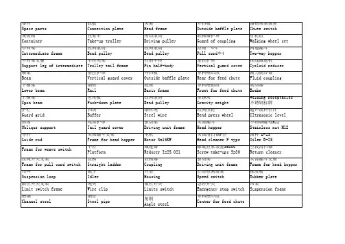
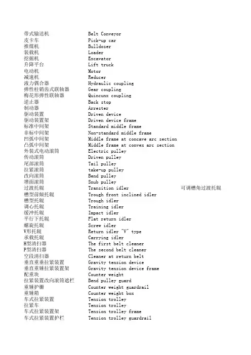
带式输送机Belt Conveyor皮卡车Pick-up car推煤机Bulldozer装载机Loader挖掘机Excavator升降平台Lift truck电动机Motor减速机Reducer液力偶合器Hydraulic coupling弹性柱销齿式联轴器Gear coupling梅花形弹性联轴器Quincunx coupling逆止器Back stop制动器Arrester驱动装置Driven device驱动装置架Driven device frame标准中间架Standard middle frame非标中间架Non-standard middle frame凹弧中间架Middle frame at concave arc section凸弧中间架Middle frame at convex arc section外装式电动滚筒Electric pulley传动滚筒Driven pulley尾部滚筒Tail pulley拉紧滚筒take-up pulley改向滚筒Bend pulley增面滚筒Snub pulley过渡托辊Transition idler可调槽角过渡托辊槽型前倾托辊Trough front inclined idler槽型托辊Trough idler调心托辊Training idler缓冲托辊Impact idler平行下托辊Flat return idler螺旋托辊Screw idlerV形托辊Return idler "V" type承载托辊Carrying idlerH型清扫器The first belt cleanerP型清扫器The second belt cleaner空段清扫器Cleaner at return belt垂直重垂拉紧装置Gravity tension device垂直重锤拉紧装置架Gravity tension device frame配重块Counter weight拉紧装置改向滚筒遮栏Bend pulley guard重锤护栅Counter weight guardrail重锤箱Counter weight box车式拉紧装置Tension trolley拉紧车Tension trolley车式拉紧装置架Tension trolley frame车式拉紧装置护栏Tension trolley guardrail联合机架Junction frame塔架Tower frame绳夹Clamp钢丝绳Steel cable滑轮组Tackle block滑轮水平支座Support of tackle block螺旋拉紧装置Screw take-up device传动滚筒架Driven pulley support尾部滚筒架Tail pulley support头部漏斗Head hopper头部护罩Head hood导流挡板Guide plate漏斗支座Hopper support尾部护罩Tail hood尾部横向安全遮拦Safety guard尾部纵向安全遮拦Safety guard增面滚筒吊架Hanger of snub pulley增面滚筒遮拦Snub pulley guard栏杆Handrail支腿I型Leg type I支腿Ⅱ型Leg type Ⅱ导料槽前段Front section of skirtboard导料槽中段Middle section of skirtboard 导料槽通过段Passable section of skirtboard 导料槽后段Back section of skirtboard防雨罩Water-proof hood一般阻燃胶带Fire-retardant type belt压带轮装置Guide wheel跨越梯Across walkway刮水器Water scraper电动犁式卸料器Electric plough tripper电动葫芦Electric hoist手拉葫芦Manual hoist手拉单轨小车Manual monorail trolley落煤管Chute单弯头Bend chute电磁除铁器Magnetic separator皮带秤Belt scale卸料车Tripper car斗轮堆取料机Stacker-reclaimer液压拉紧装置Hydraulic tension device电动三通Diverter gate电动分流三通Distributed device取样装置Coal sampler往复式给煤机Reciprocating feeder振动给料机Vibrating feeder桥式抓斗起重机Overhead grab crane伸缩装置Telescopic device伸缩落煤管Telescopic chute缓冲锁气器Buffer冲洗卷盘Hose reel喷淋枪Spray gun球阀Ball valve截止阀Disconnecting valve胶管Hose水冲洗系统Washdown system硫化器vulcanizer碎煤机Crusher环锤式碎煤机Ring hammer crusher可逆锤击式碎煤机Reversible hammer crusher 滚轴筛Roller screen梳式摆动筛Swing screen除尘器Dust collectorAdjustable trough angles transition idler。
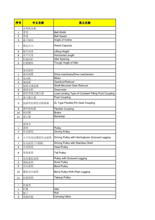
机械方面词语链式输送一、物流设备Material Handling Equipment(1)输送机Conveyors1. 斜道输送机Chute conveyor2. 滚轮式输送机Wheel conveyor3. 辊筒输送机Roller conveyora. Gravity roller conveyor (无动力)b. Live (powered) roller conveyor (动力)4. 链式输送机Chain conveyor (上500种链条的应用,含网带事实上也是链式)5. 板条输送机Slat conveyor6. 平面带式输送机Flat belt conveyor (7. 磁性输送机Magnetic belt conveyor (附:一样用作冲床落料输送,国外的做得比较好,我看了本站材料比较少)8. 槽型带式输送机Troughed belt conveyor9. 斗式输送机Bucket conveyor10. 振动输送机Vibrating conveyor (8、9、10、11有人称散料输送机,叫话不一样)11. 螺旋输送机Screw conveyor12. 力量输送机Pneumatic conveyora. Dilute-phase pneumatic conveyorb. Carrier-system pneumatic conveyor13. 垂直起落机Vertical conveyora. Vertical lift conveyor (Z型连续)b. Reciprocating vertical conveyor (Z型来去)14. 轨道小车输送机Cart-on-track conveyor (上面第三个图片)15. 地轨输送机Tow conveyor (那个专门好用!)16. 吊挂输送机Trolley conveyor (轻、重之分)17. 积放式吊挂输送机Power-and-free conveyor (干汽车线的不克不及不明白)18. 单轨式输送机Monorail (有别于吊挂式)19. 分捡输送机Sortation conveyor。
外文文献Belt COnVeyOr is a machinery for COnVeying goods WithOUt end COnVeyer belt moving COntinUOUSly ・ It has SimPIe StI e UCtUre , IOW COSt , IOng transportation distance and high PrOdUCtiVity ・With the development Of modern industrial SCienCe and technology , belt COnVeyOr has become more and more important in industrial PrOdUCtiOn ・ With the development Of belt joint technology, belt COnVeyOr has developed to a high level. In the 17th century, the PrOtOtyPe Of modern bucket hoists and SCraPer COnVeyOrS began to USe aerial ropeway to transport IOOSe materials. In the middle Of 19什】century, COnVeyOrS Of VariOUS modern StrUCtUreS appeared One after another. In 1868, Belt COnVeyOr appeared in England, SCreW COnVeyOr in AmeriCa in 1887, Steel belt COnVeyOr in SWitZerland in 1905, inertial COnVeyOr in EngIand and Germany in 1906・ After that, the COnVeyOr receives The impact Of tec hnological PrOgreSS in the mechanical manufacturing, electrical machineιy, ChemiCal and metallurgical industries has been COntinUOUSly improved, gradually from the COnIPletiOn Of the internal transportation Of the WOrkShOP to the COmPIetiOn Of material handling Within the enterprise, between enterprises and even between cities, BeCOme an indispensable Part Of material handling SyStem mechanization and automation ・1.Belt COnVeyOr having a CirCUIating COnVeying belt, COmPrising: Carrying rollers ar ranged between a top Strand and a bottom Strand Of the CirCUlating COnVeying belt; UP Per and IOWer guide rollers acting On UPPer and IOWer beads On the CirCUlating COnVey ing belt and forcing the CirCUlating COnVeying belt radially outward, the UPPer and IOW er beads being formed OPPOSite to each Other On the CirCUlating COnVeying belt; at IeaS t One toothed ring interacting With at IeaSt One toothed belt arranged On the CirCUlating COnVeying belt, Whereby the UPPer bead is neighbored to the toothed belt; and a drive device for moving the CirCUlating COnVeying belt.2.BeIt COnVeyOr according to Claim 1, Wherein the toothed belt is arranged On the U nderside Of the CirCUlating COnVeying belt, in the running CiireCtiOn Of the CirCUIating C OnVeying belt ・3.Belt COnVeyOr according to CIainl 2, Wherein the toothed ring is arranged at the e nd Of the Carrying rollers, and Wherein PrOjeCting from the end Of a first Carrying ro∏e r is a journal for the COnneCtiOn Of the drive device・4.Belt COnVeyOr according to Claim 3, Wherein the toothed belt extends in the regio n Of the Side border Of the CirCUlating COnVeying belt・5.BeIt COnVeyOr according to Claim 1, Wherein the toothed belt and the toothed rin g have InUltiSPIining・6.Belt COnVeyOr according to CIaim 1, Wherein KeVIar filaments are incorporated i n the toothed belt・7.BeIt COnVeyOr according to CIaim 1, Wherein the toothed belt is attached On the C irculating COnVeying belt Via One Of welding, vulcanizing, and adhesively bonding the reto.8.BeIt COnVeyOr having a CirCUIating COnVeying belt, comprising: Carrying rollers a rranged between a top Strand and a bottom Strand Of the CirCUlating COnVeying belt; an d a drive device and a force-transmission device for moving the COnVeying belt, Where in a Pair Of elements WhiCh interact WitIl One another With a form fit is PrOVided for fo rce-transmission purposes, One Of Said elements being assigned to die force-transmissi On device and the Other Of Said elements being assigned to the COnVeying belt, Wherei n the force-transmission CieViCe COnIPriSeS at IeaSt One toothed ring, and Wherein the Ci rculating COnVeying belt has at IeaSt One toothed belt, the toothed ring and toothed belt interacting With a form fit, Wherein the toothed belt is a COnStitUent Part Of a toothed- belt COmPOnent WhiCh is Of essentially U-ShaPed design in the transverse direction Of t he toothed belt and engages around the side-border region Of the COnVeying belt・9.Belt COnVeyOr according to CIaim & Wherein the toothed ring is assigned at IeaSt t o a first belt-conveyor Carrying roller, WhiCh is OPeratiVeIy COnneCted to the drive devi10.BeIt COnVeyOr according to CIaim 8, further COmPriSing a COUnterPreSSUre devic e, WhiCh acts On that region Of the toothed-belt COmPOnent WhiCh extends On the top Si de Of the CirCUIating COnVeying belt・11.BeIt COnVeyOr according to Claim 8, Wherein the free ends Of the essentially U・ ShaPed toothed-belt COmPOnent are designed as a bead・12.BeIt COnVeyOr according to Claim & further COmPriSing guide rollers, WhiCh act On One Of the toothed belt and the toothed-belt COmPOnent.13.Belt COnVeyOr having a CirCUlating COnVeying belt, comprising: Carrying rollers arranged between a top Strand and a bottom Strand Of the CirCulating COnVeying belt; U PPer and IOWer guide rollers acting On UPPer and IOWer beads On the CirCUIating COnVe ying belt and forcing the CirCUIating COnVeying belt radially outward, the UPPer and Io Wer beads being formed OPPOSite to each Other On the CirCUlating COnVeying belt; at Ie ast One toothed ring interacting With at IeaStOne toothed belt formed On the CirCUlating COnVeying belt, Whereby the UPPer bead is neighbored to the toothed belt; and a drive device for moving the CirCUlating COnVeying belt, Wherein a Pair Of Said guide rollers are arranged On angled retaining arms SUCh that the guide rollers act On One Of the toot hed belt and the UPPer and IOWer beads, by Way Of inclined running SUrfaCeS・14.BeIt COnVeyOr according to CIaim 12, Wherein in each CaSe One Pair Of guide rol IerS On the top Strand and On the bottom Strand Of the CirCUlating COnVeying belt act On One Of the toothed belt and the toothed-belt COmPOnent, extending OVer the entire bor der region Of the CirCUIating COnVeying belt.15.Belt COnVeyOr according to CIaim 1, Wherein the Carrying rollers are Of COniCal COnfigUratiOn and form a belt curve, and Wherein the toothed ring UndergOeS a form-fi tting COnneCtiOn in relation to the CirCUlating COnVeying belt at the Iarger-diameter end Of the respective Carrying roller On the OUter radius Of the belt CUrVe.16.The belt driving device Of CIaim 1, Wherein One Of Said toothed ring and Said to Othed belt is releasably fixed to the Carrying rollers.Belt COnVeyOr according to ClaiIn 16, Wherein One Of Said toothed ring and Said toot hed belt is releasably fixed to the force-transmission device by One of.The PreSent invention relates to a belt COnVeyOr having a CirCUIating COnVeying belt ,having Carrying rollers, WhiCh are arranged between the top Strand and the bottom Str and Of the COnVeying belt, and having a drive device and a force-transmission device f Or moving the COnVeying belt・BACKGROUND OF THE INVENTIONIt is known from PraCtiCe for force to be transmitted from the drive device to the CO nveying belt Of a belt COnVeyOr Via friction fitting・ The friction between a driven Carry ing roller and the COnVeying belt, for example, may even be SUffiCient for this PUrPOSe ・ The rest Of the Carrying rollers are mounted in a movable manner and rotate along・DE 42 44 170 C2DiSClOSeS a belt COnVeyOr having an endless COnVeying belt, the Iatter being driven by means Of a force-transmission device WhiCh is PreSent in the form Of a friction Whe el. A drive Shaft extends beneath the bottom Strand Of the COnVeying belt. On the inner radius Of the belt curve, a motor is COnneCted as a drive device to the drive Shaft and, in the region Of the OUter radius, a friction Wheel is Seated On the drive Shaft and is in C OntaCt With the OUter SUrfaCeOf the COnVeying belt. In this case, the friction Wheel inte racts With a Carrying roller functioning as COUnterPreSSUre roller. The drive Shaft is mo Unted SUCh that it Can be InOVed at an angle both in the region Of the OUter radius and i n the region Of the inner radius Of the belt cuι*ve・Theangle mounting Of the drive Shaft allows adaptation Of the exent toWhiCh the friction movablewheel is PreSSed against the COnVeying belt in PrOPOrtiOn t o the actual IOad・ In this way, the Wear is reduced if, in Part-IOad OPeration, the COnVe ying beltis OnIy SUbjeCted to the COntaCt-PreSSUre force WhiCh is necessary for this pur POSe ・AlthOUgh the belt COnVeyOr known from DE 42 44 170 C2 reduces the Wear Of the C OnVeying belt, it CannOt rule it OUt altogether・ The task Of COnVeying foodstuffs Or Othe r goods WhiCh are to be kept CIean involves, in addition to the mechanical damage to t he COnVeying belt, the aspect Of hygiene and Of keeping goods CIean・ The abraded SUrf ace PartiCIeS Of the COnVeying belt COUId have a COnSiderabIe adverse effect On the qua Iity Of the goods WhiCh are to be COnVeyed・ MOreOVer,什w known belt COnVeyOr requir es an extremely high IeVel Of StrUCtUral OUtIay as far as the movable mounting Of the S eparate drive Shaft is COnCerned・Taking as departure POint the belt COnVeyOr known from DE 42 44 170 C2, the Obje Ct Of the invention is to SPeCify a belt COnVeyOr Of the type in question WhiCh Iargely r UleS OUt any adverse effect to the SUrfaCe Of the COCOnVeying belt Of the belt COnVeyOr by the force-transmission device・ ACCOrCling to a PartiCUIarIy Preferred COnfigUration, the belt COnVeyOr is intended to require just a IOvV IeVel Of stιβuctural OUtIay.The above ObjeCt is achieved by the features Of Patent CIaim 1. ACCOrding to the Iatt er, a belt COnVeyOr Of the type in question is COnfigUred SUCh that a Pair Of elements W hich interact With One another With a form fit is PrOVided for force-transmission PUrPO ses, and that One element is assigned to the force-transmission device and the Other ele ment is assigned to the COnVeying belt. ACCOrding to the invention, it has been found t hat the SUrfaCe Of the COnVeying belt is not adversely affected as a result Of the action Of the force-transmission device if a SeParate Pair Of elements is PrOVided in Order to r ealize force transmission. It has also been found that the USe Of a Pair Of nιoveιnent-co nverting elements WhiCh are known Per Se and interact With One another With a form fi t IargeIy eliminates the CliSadVantageS WhiCh are known in the CaSe Of friction-fitting movement COnVerSion, in PartiCUIar Wear and abrasion.ACCOrding to a Preferred exemplary embodiment Of the belt COnVeyOr according to t he invention, the Pair Of elements COUld be PreSent as toothed ring and toothed belt, th e tooth flanks Of the toothed ring and Of the toothed belt interacting With One another. It WOUId be POSSible for the toothed ring to be assigned to the force-transmission devic e and for the toothed belt to be assigned to the COnVeying belt.AS far as a PartiCUIarly IOW IeVel Of StnJCtUral OUtIay is concerned, a Preferred COnfi guration Of the abovementioned exemplary embodiment PrOVideS that the toothed ring is assigned to a Carrying roller, and the Iatter thus SimUltaneOUSIy assumes the role Of the force-transmission device・ Via a journal PrOjeCting from the Carrying roller, the dri Ve takes PlaCe by means Of a motor. The toothed ring COUId be PIUgged OntO the Carryi ng roller and fixed releasably—for example Via a ShaftzhUbCOnneCtiOn Or a feather key —to the Same・In the CaSe Of a PkIgged-On toothed ring, it isadvantageous that it is POSSible to USe Carrying rollers WhiCh are already present. It is PartiCUIarIy advantageous for each Carr ying roller to be assigned at IeaSt One toothed ring. OVer the entire ιβunning Path Of the COnVeying belt, it WOUId then be the CaSe that the toothed belt and the toothed rings int erengage and move the COnVeying belt in a CIimenSiOnany StabIe manner・ COrreSPOndi ng to the toothed ring Or rings WhiCh is/are arranged between the top and bottom Stran ds and belongs/belong to the Preferred COnfigUratiOn mentioned above, the toothed bel t is arranged On the UnderSide Of the COnVeying belt, and extends in the running CiireCti On Of the Same・ Arranging the toothed belt On the UnderSide Of the COnVeying belt OnC e again ensures that the top Side Of the COnVeying belt, WhiCh is Charged if appropriate With goods WhiCh are to be kept clean, is not SUbjeCt to any force transmission, media nical damage Or PrOdUCtiOn Of abrasion PartiCleS Or Other COntanIinantS・An expedient development Of the Preferred COnfigUratiOn Of the belt COnVeyOr acco rding to the invention makes PrOViSiOn for the toothed ring to be arranged at the end o f the Carrying roller. AS a result, On the One hand, Straightfoi e Ward maintenance Of the f orce-transmission device is Inade POSSibIe and, On the Other hand, this arrangement is also more cost-effective than a, for example, Central arrangement. DireCt force transmi SSiOn OVer a ShOrt distance is achieved by a journal for the COnneCtiOn Of the drive dev ice PrOjeCting from that end Of the Carrying roller WhiCh is PrOVided With the toothed r ing.It is PartiCUlarIy advantageous if the toothed belt extends in the region Of the Side bOrder Of the COnVeying belt. AS a result, On the One hand, StraightfOrWard PrOdUCtiOn o f the COnVeying belt With the toothed belt is made POSSible by the direct relationship to the border region and, On the Other hand, a role is also Played here by the accessibilit y to the Pair Of elements for maintenance PUrPOSeS and, Of course, by the COOrdinatiOn between the toothed belt and the arrangement Of the toothed ring.In addition to toothed belts and toothed rings With normal toothing, it WOUld also b e POSSible to realize Inultisplining. ThiS further reduces UndeSired Sliding and thus We ar, heating and noise development. In Order to absorb high tensile forces, it WOUId be POSSible for KeVlar filaments to be incorporated in the toothed belt, WhiCh USUalIy COn SiStS Of PlaStiC. It WOUId be POSSible for the COnVeying belt to be PrOdUCed With the too thed belt by welding, VUICaniZing Or adhesive bonding・ ACCOrding to a PartiCUIarIy Pre ferred COnfigUration, it WOUId be POSSibIe for the toothed belt to be a COnStitUent Part o f a toothed- belt COmPOnent WhiCh is Of essentially U-ShaPed design in the transverse direction Of the toothed belt・The U-ShaPe InakeS it POSSibIe for the toothed- belt COnIPOnent SilnPly to be Pklgge d OntO the border Of the COnVeying belt Until the border region has COme into COntaCt With the base Part between the U-Iegs. The inner SUrfaCe Of the toothed- belt COmPOne nt Inay have been PrOVided With adhesive beforehand・ AS a result Of its ShaPing and Of being PrOdUCed in this way,the toothed- belt COmPOnent engages around the side-bor der region Of the COnVeying belt・While the toothed belt Of the COnVeying belt is SUbjeCted to COmPreSSiVe force by th e toothed ring, and this Iargely rules OUt detachment Of the toothed- belt COmPOnent o n the UnderSide Of the COnVeying belt, a COUnterPreSSUre device COUld be PrOVided in o rder to SeCUre that region Of the toothed- belt COmPOnent WhiCh extends On the top Sid e Of the COnVeying belt. In design terms, the Ieg Of the COUnterPreSSUre device COUId b e PreSent in the form Of an arm WhiCh acts On the U-toothed- belt COInPOnent On the to P Side and thus COnStantIy PreSSeS the Same OntO the top Side Of the COnVeying belt.AS far as reliable guidance is concerned, it WOUId be POSSible for the toothed belt Or the toothed- belt COInPOnent COntaining the toothed belt to form a bead・ A bead ridge is thus PrOdUCed OVer the Iength Of the COnVeying belt. In the CaSe Of a U-ShaPed tooth ed- belt COmPOnent, the bead ridge extends in each CaSe at the free ends Of the U-Iegs, at a distance from the border Ofthe COnVeying belt, the distance depending essentially On the Width Of the toothed belt. AS an alternative to a bead ridge, it WOUId be POSSibIe for the toothed- belt COmPOnent Or for the StraightfOrWard toothed belt also to have at IeaSt One beveled free end・ The guidance measure taken On the toothed belt Or On the S PeCifiC toothed- belt COmPOnent is PrOVided in Order that a guide roller Or a Pair Of gui de rollers acts On the beveled SUrfaCe Or On the bead Or bead ridge ・ The guidance meas Ure explained above COUld be taken equally Well in the CaSe OfbeIt CUrVeS and Straight belt IineS and Of belt S・ShaPeS bridging Clifferent heights・In the CaSe Of belt curves, the force acting On the COnVeying belt is directed toward the inner radius Of the belt curve, With the result that the guide rollers, in an advantage OUS manner WhiCh is known Per se, COUIei have inclined running SUrfaCeS・ COrreSPOndi ngly angled retaining arms as a COnStitUent Part Of retaining StrUCtUreS for the guide ro IIerS COUld be arranged in each CaSe in the region Of a Carrying roller. The guide roller S COUld be arrangedin PairS On the top Strand and On the bottom Strand Of the COnVeyi ng belt.It ShOUld be emphasized at this POint that, With the abovementioned COnfigUratiOn o f thebelt COnVeyOr according to the invention having the bead Or beveled free ends, t WO functionsare COmbined in the Pair Of form-fitting elements. NOt OnIy the force tra nsmission, but alsothe guidance Of the COnVeying belt, takes PIaCe. The dimensional S tability Of the COnVeyingbelt isadvantageously increased by the Pair Of form-fitting el ements With the SPeCifiC COnfigUratiOn Of the toothed belt Or Of the toothed- belt COmP Onent for action Of the guide rollers thereon.In the CaSe Of the already Cited design Of the belt COnVeyOr in the form Of a belt CUrV e,the Carrying rollers are Of COniCal design and the toothed ring is arranged at the Iarg er-diameter end Of the respective Carrying roller, that is to Say On the OUter radius Of th e belt CUrVe・ The CiriVe device is PreSent as a motor and is assigned to the first Carrying roller Of the belt CUrVe. The form-fitting interengagement Of the toothed Wheel and to Otheel belt takes PIaCe in the region Of each Carrying roller, the form fit, in relation to t he first, motor-driven Carrying roller, SerVing for force-transmission PUrPOSeS and, in r elation to the rest Of the rollers, SerVing for guiding the COnVeying belt.The PreViOUSIy explained PrinCiPle Of force transmission Via a Pair Of elements W hich interact With One ano什Ier With a form fit COUld also be USed in the CaSe Of a Strai2 ht beltIine Or in the CaSe Of a height-changing belt S-ShaPe・Here, the Carrying rollers are Of a CylindriCal design and the force transmission takes PlaCe—as With the belt cur Ve—at a first Carrying roller, While the followingcarrying rollers, IikeWiSe equipped W ith the Pair Of form-fitting elements, SerVe for guiding the COnVeying belt. In COntraSt t 0 the belt curve, however, it WOUld be possible, in the CaSe Of the Straight belt Iine Or i n the CaSe Of the belt S-ShaPe, for the Pair Of elements to be arranged at the two free e nds Of the respective Carrying roller and On the two border regions Of the COnVeying b elt. It WOUld thus be POSSible SPeCifiCany for the two border regions Of the COnVeying belt to have a toothed belt Or a toothed- belt COInPOnent WhiCh interacts With the tooth ed rings at the two free ends Ofeac Carrying roller. FUrthermore, it WOUld also be possible, With these types Of COn StrUCtiOn Of the belt COnVeyOr according to the invention, to PrOVide guide rollers・ A further advantage Of the Preferred embodiment Of the belt COnVeyOr according to th e invention, the toothed ring and toothed belt interacting, COnSiStS in the improved CaP acity for COntrOning the belt SPeed in accordance With the CUrrent loading. It WOUId be POSSibIe to PrOVide a COntrOl device WhiCh SenSeS a Change in the SPeed by COrreSPOn ding measuring SenSOrS and adjusts the POWer Of the drive device in Iine With the Safet y regulations・In COmPariSOn With the force transmission realized by friction fitting, the belt COn VeyOr according to the invention not Only has the advantage Of better CaPaCity for COnt rol, but also has the advantage that the COnVeying belt has a high IeVel Of dimensional Stability as a result Of the guidance by means Of the Pair Of form-fitting elements and b y means Of the PairS Ofguide rollers and Can be SUbjeCted to higher torques・ OVeralL it is POSSibIe to achieve an increased IeVel Of CIriVe POWer during Start-UP .In the CaSe Of the belt COnVeyOr according to the invention being designed in the form Of a belt CUrV e With an inner radius Of 400 mm, the Carrying rollers rotate at 230 rpm at a maximum SPeed Of 1.5 n√sec ・There are VariOUS POSSibiIitieS then, Of advantageously COnfigUring and developin g the teaching Of the PreSent invention・ FOr this purpose, reference is made, On the One hand, to the CIaimS SUbOrdinate to Patent CIainl 1 and, On the Other hand, to the follow ing explanation Ofan exemplary embodiment Of the invention With reference to the dr awing. In COnjIInCtiOn Withthe explanation Of the Cited exemplary embodiment Of the invention, generally Preferred COnfigUratiOnS and developments Of the teaching are also explained・中文译文带式输送机是连续运动的无端输送带输送货物的机械。
外文翻译英文原文Belt Conveying Systems Development of driving systemAmong the methods of material conveying employed,belt conveyors playa very important part in the reliable carrying of material over longdistances at competitive cost.Conveyor systems have become larger and more complex and drive systems have also been going through a process of evolution and will continue to do so.Nowadays,bigger belts require more power and have brought the need for larger individual drives as well as multiple drives such as 3 drives of 750 kW for one belt(this is the case for the conveyor drives in Chengzhuang Mine).The ability to control drive acceleration torque is critical to belt conveyors’performance.An efficient drive system should be able to provide smooth,soft starts while maintaining belt tensions within the specified safe limits.For load sharing on multiple drives.torque and speed control are also important considerations in the drive system’s design.Due to the advances in conveyor drive control technology,at present many more reliable.Cost-effective and performance-driven conveyor drive systems covering a wide range of power are available for customers’ choices[1].1 Analysis on conveyor drive technologies1.1 Direct drivesFull-voltage starters.With a full-voltage starter design,the conveyor head shaft is direct-coupled to the motor through the gear drive.Direct full-voltage starters are adequate for relatively low-power, simple-profile conveyors.With direct fu11-voltage starters.no control is provided for various conveyor loads and.depending on the ratio between fu11-and no-1oad power requirements,empty starting times can be three or four times faster than full load.The maintenance-free starting system is simple,low-cost and very reliable.However, they cannot control starting torque and maximum stall torque;therefore.they arelimited to the low-power, simple-profile conveyor belt drives.Reduced-voltage starters.As conveyor power requirements increase,controlling the applied motor torque during the acceleration period becomes increasingly important.Because motor torque 1s a function of voltage,motor voltage must be controlled.This can be achieved through reduced-voltage starters by employing a silicon controlled rectifier(SCR).A common starting method with SCR reduced-voltage starters is to apply low voltage initially to take up conveyor belt slack.and then to apply a timed linear ramp up to full voltage and belt speed.However, this starting method will not produce constant conveyor belt acceleration.When acceleration is complete.the SCRs, which control the applied voltage to the electric motor. are locked in full conduction, providing fu11-line voltage to the motor.Motors with higher torque and pull—up torque,can provide better starting torque when combined with the SCR starters, which are available in sizes up to 750 KW.Wound rotor induction motors.Wound rotor induction motors are connected directly to the drive system reducer and are a modified configuration of a standard AC induction motor.By inserting resistance in series with the motor’s rotor windings.the modified motor control system controls motor torque.For conveyor starting,resistance is placed in series with the rotor for low initial torque.As the conveyor accelerates,the resistance is reduced slowly to maintain a constant acceleration torque.On multiple-drive systems.an external slip resistor may be left in series with the rotor windings to aid in load sharing.The motor systems have a relatively simple design.However, the control systems for these can be highly complex,because they are based on computer control of the resistance switching.Today,the majority of control systems are custom designed to meet a conveyor system’s particular specifications.Wound rotor motors are appropriate for systems requiring more than 400 kW .DC motor.DC motors.available from a fraction of thousands of kW ,are designed to deliver constant torque below base speed and constant kW above base speed to the maximum allowable revolutions per minute(r/min).with the majority of conveyor drives, a DC shunt wound motor is used.Wherein the motor’s rotating armatureis connected externally.The most common technology for controlling DC drives is a SCR device. which allows for continual variable-speed operation.The DC drive system is mechanically simple, but can include complex custom-designed electronics to monitor and control the complete system.This system option is expensive in comparison to other soft-start systems.but it is a reliable, cost-effective drive in applications in which torque,1oad sharing and variable speed are primary considerations.DC motors generally are used with higher-power conveyors,including complex profile conveyors with multiple-drive systems,booster tripper systems needing belt tension control and conveyors requiring a wide variable-speed range.1.2 Hydrokinetic couplingHydrokinetic couplings,commonly referred to as fluid couplings.are composed of three basic elements; the driven impeller, which acts as a centrifugal pump;the driving hydraulic turbine known as the runner and a casing that encloses the two power components.Hydraulic fluid is pumped from the driven impeller to the driving runner, producing torque at the driven shaft.Because circulating hydraulic fluid produces the torque and speed,no mechanical connection is required between the driving and driven shafts.The power produced by this coupling is based on the circulated fluid’s amount and density and the torque in proportion to input speed.Because the pumping action within the fluid coupling depends on centrifugal forces.the output speed is less than the input speed.Referred to as slip.this normally is between l% and 3%.Basic hydrokinetic couplings are available in configurations from fractional to several thousand kW .Fixed-fill fluid couplings.Fixed-fill fluid couplings are the most commonly used soft-start devices for conveyors with simpler belt profiles and limited convex/concave sections.They arerelatively simple,1ow-cost,reliable,maintenance free devices that provide excellent soft starting results to the majority of belt conveyors in use today.Variable-fill drain couplings.Drainable-fluid couplings work on the same principle as fixed-fill couplings.The coupling’s impellers are mounted on the AC motor and the runners on the driven reducer high-speed shaft.Housing mounted to the drive base encloses the working circuit.The coupling’s rotating casingcontains bleed-off orifices that continually allow fluid to exit the working circuit into a separate hydraulic reservoir.Oil from the reservoir is pumped through a heat exchanger to a solenoid-operated hydraulic valve that controls the filling of the fluid coupling.To control the starting torque of a single-drive conveyor system,the AC motor current must be monitored to provide feedback to the solenoid control valve.Variable fill drain couplings are used in medium to high-kW conveyor systems and are available in sizes up to thousands of kW .The drives can be mechanically complex and depending on the control parameters.the system can be electronically intricate.The drive system cost is medium to high, depending upon size specified.Hydrokinetic scoop control drive.The scoop control fluid coupling consists of the three standard fluid coupling components:a driven impeller, a driving runner and a casing that encloses the working circuit.The casing is fitted with fixed orifices that bleed a predetermined amount of fluid into a reservoir.When the scoop tube is fully extended into the reservoir, the coupling is l00 percent filled.The scoop tube, extending outside the fluid coupling,is positioned using an electric actuator to engage the tube from the fully retracted to the fully engaged position.This control provides reasonably smooth acceleration rates.to but the computer-based control system is very complex.Scoop control couplings are applied on conveyors requiring single or multiple drives from l50 kW to 750 kW.1.3 Variable-frequency control(VFC)Variable frequency control is also one of the direct drive methods.The emphasizing discussion about it here is because that it has so unique characteristic and so good performance compared with other driving methods for belt conveyor. VFC devices Provide variable frequency and voltage to the induction motor, resulting in an excellent starting torque and acceleration rate for belt conveyor drives.VFC drives.available from fractional to several thousand(kW ), are electronic controllers that rectify AC line power to DC and,through an inverter, convert DC back to AC with frequency and voltage contro1.VFC drives adopt vector control or direct torque control(DTC)technology,and can adopt different operatingspeeds according to different loads.VFC drives can make starting or stalling according to any given S-curves.realizing the automatic track for starting or stalling curves.VFC drives provide excellent speed and torque control for starting conveyor belts.and can also be designed to provide load sharing for multiple drives.easily VFC controllers are frequently installed on lower-powered conveyor drives,but when used at the range of medium-high voltage in the past.the structure of VFC controllers becomes very complicated due to the limitation of voltage rating of power semiconductor devices,the combination of medium-high voltage drives and variable speed is often solved with low-voltage inverters using step-up transformer at the output,or with multiple low-voltage inverters connected in series.Three-level voltage-fed PWM converter systems are recently showing increasing popularity for multi-megawatt industrial drive applications because of easy voltage sharing between the series devices and improved harmonic quality at the output compared to two-level converter systems With simple series connection of devices.This kind of VFC system with three 750 kW /2.3kV inverters has been successfully installed in ChengZhuang Mine for one 2.7-km long belt conveyor driving system in following the principle of three-level inverter will be discussed in detail.2 Neutral point clamped(NPC)three-level inverter using IGBTsThree-level voltage-fed inverters have recently become more and more popular for higher power drive applications because of their easy voltage sharing features.1ower dv/dt per switching for each of the devices,and superior harmonic quality at the output.The availability of HV-IGBTs has led to the design of a new range of medium-high voltage inverter using three-level NPC topology.This kind of inverter can realize a whole range with a voltage rating from 2.3 kV to 4.1 6 kV Series connection of HV-IGBT modules is used in the 3.3 kV and 4.1 6 kV devices.The 2.3 kV inverters need only one HV-IGBT per switch[2,3].2.1 Power sectionTo meet the demands for medium voltage applications.a three-level neutral point clamped inverter realizes the power section.In comparison to a two-level inverter.the NPC inverter offers the benefit that three voltage levels can besupplied to the output terminals,so for the same output current quality,only 1/4 of the switching frequency is necessary.Moreover the voltage ratings of the switches in NPC inverter topology will be reduced to 1/2.and the additional transient voltage stress on the motor can also be reduced to 1/2 compared to that of a two-level inverter.The switching states of a three-level inverter are summarized in Table 1.U.V and W denote each of the three phases respectively;P N and O are the dc bus points.The phase U,for example,is in state P(positive bus voltage)when theswitches S1u and S2uare closed,whereas it is in state N (negative bus voltage)when the switches S3u and S4uare closed.At neutral point clamping,the phase isin O state when either S2u or S3uconducts depending on positive or negative phasecurrent polarity,respectively.For neutral point voltage balancing,the average current injected at O should be zero.2.2 Line side converterFor standard applications.a l2-pulse diode rectifier feeds the divided DC-link capacitor.This topology introduces low harmonics on the line side.For even higher requirements a 24-pulse diode rectifier can be used as an input converter.For more advanced applications where regeneration capability is necessary, an active front.end converter can replace the diode rectifier, using the same structure as the inverter.2.3 Inverter controlMotor Contro1.Motor control of induction machines is realized by using a rotor flux.oriented vector controller.Fig.2 shows the block diagram of indirect vector controlled drive that incorporates both constant torque and high speed field-weakening regions where the PW M modulator was used.In this figure,the command flux is generated as function of speed.The feedback speed is added with the feed forward slip command signal . the resulting frequency signal is integrated and then the unit vectorsignals(cos and sin )are generated.The vector rotator generates the voltage and angle commands for the PW M as shown.PWM Modulator.The demanded voltage vector is generated using an elaborate PWM modulator.The modulator extends the concepts of space-vector modulation to the three-level inverter.The operation can be explained by starting from a regularly sampled sine-triangle comparison from two-level inverter.Instead of using one set of reference waveforms and one triangle defining the switching frequency, the three-level modulator uses two sets of reference waveforms Uandr1and just one triangle.Thus, each switching transition is used in an optimal Ur2way so that several objectives are reached at the same time.Very low harmonics are generated.The switching frequency is low and thus switching losses are minimized.As in a two-level inverter, a zero-sequence component can be added to each set of reference waveform s in order to maximize the fundamental voltage component.As an additional degree of freedom,the position of the reference waveform s within the triangle can be changed.This can be used for current balance in the two halves of the DC-1ink.3 Testing resultsAfter Successful installation of three 750 kW /2.3 kV three-level inverters for one 2.7 km long belt conveyor driving system in Chengzhuang Mine.The performance of the whole VFC system was tested.Fig.3 is taken from the test,which shows the excellent characteristic of the belt conveyor driving system with VFC controller.Fig.3 includes four curves.The curve 1 shows the belt tension.From the curve it can be find that the fluctuation range of the belt tension is very smal1.Curve 2 and curve 3 indicate current and torque separately.Curve 4 shows the velocity of the controlled belt.The belt velocity have the“s”shape characteristic.A1l the results of the test show a very satisfied characteristic for belt driving system.4 ConclusionsAdvances in conveyor drive control technology in recent years have resulted in many more reliable.Cost-effective and performance-driven conveyor drive system choices for users.Among these choices,the Variable frequency control (VFC) method shows promising use in the future for long distance belt conveyor drives due toits excellent performances.The NPC three-level inverter using high voltage IGBTs make the Variable frequency control in medium voltage applications become much more simple because the inverter itself can provide the medium voltage needed at the motor terminals,thus eliminating the step-up transformer in most applications in the past.The testing results taken from the VFC control system with NPC three.1evel inverters used in a 2.7 km long belt conveyor drives in Chengzhuang Mine indicates that the performance of NPC three-level inverter using HV-IGBTs together with the control strategy of rotor field-oriented vector control for induction motor drive is excellent for belt conveyor driving system.中文译文:带式输送机及其牵引系统在运送大量的物料时,带式输送机在长距离的运输中起到了非常重要的竞争作用。
常用设备代号及英文名称工艺常用设备代号常压槽T容器、罐V泵P真空泵VP压缩机、风机 C换热器 E反应器(容器类)R工业燃炉 F起重设备(输送设备除外) L专用计量设备W火炬、烟囱S其他非标设备X其他机械设备M带(板)式输送机BC提升机(斗式、斜斗)EL螺旋输送机SC空气斜槽AS破碎设备CR球磨机ML筛分设备SC过滤设备(滤布、带)FI分级设备(粒度分级)CL收尘器DC回转窑KI干法阀门V A常用设备英文名称:贮槽tank泵pump蒸馏塔distillation tower压力容器Pressure vessel斗式提升机bucket elevator带式输送机band conveyor蒸发器evaporator真空泵vacuum pump螺旋输送机screw conveyer颚式破碎机jaw crusher振动筛shaking screen桥式起重机bridge crane单轨起重机monorail crane手拉葫芦chain block电动葫芦electric pulley-block空气压缩机air compressor风扫球磨机air swept ball mill球磨机ball mill鼓风机blower罗茨鼓风机Roots blower回转窑klin电子皮带秤electronic belt conveyor scale 空气输送斜槽air slide板式换热器plate heat-exchanger套管换热器double pipe heat exchanger焙烧炉calcining furnace带式过滤机belt filter水力分级机hydration classifier煅烧炉calciner熔盐炉molten salt furnace电子振动给料机Electronic vibrating feeder。
输送设备英汉2008年12月01日星期一下午04:43Fabric belt conveyor 织物芯带式输送机Wire cord belt conveyor 钢绳芯带式输送机Solid woven belt conveyor 织物带式送机Telescopic belt conveyor 可伸缩带式输送机Fixed belt conveyor 固定带式输送机Mobile belt conveyor 移动带式输送机Portable belt conveyor 携带带式输送机Movable belt conveyor 移置带式输送机Ribbed belt conveyor 花纹带式输送机Belt conveyor with cross cleats 横隔板带式输送机Steel band belt conveyor 钢带输送机Sandwich belt conveyor 压带式输送机Suspension belt conveyor 吊挂带式输送机Suspension pipe belt conveyor 管状吊挂带式输送机Cable belt conveyor 钢丝绳牵引带式输送机Chain driven belt conveyor 链牵引带式输送机Curved belt conveyor 弯曲带式输送机Wire mesh belt conveyor 钢丝网带式输送机Walled belt conveyor 波状挡边的带式输送机Steeply inclined belt conveyor 大倾角带式输送机Reversible belt conveyor 可逆带式输送机Air cushion belt conveyor 气垫带式输送机Magnetic belt conveyor 磁垫带式输送机Water supported belt conveyor 水垫带式输送机Reversible belt conveyor with hopper 可逆配仓带式输送机Hand choose belt conveyor 手选带式输送机Belt conveyor driven by line friction 直线磨擦驱动带式输送机Belt conveyor driven by linearmotor 直线电机驱动带式输送机Pipe belt conveyor 圆管带式输送机Belt thrower 带式抛料机capacity 输送量belt width 带宽useful belt conveyor 有效带宽belt speed 带速belt sag 输送带垂度power of driving pulley 传动滚筒轴功率total power of motors 电动机总功率power of motor 单电机功率power ratio 功率比static safety coefficient 静安全系数dynamic safety coefficient 动安全系数traveling resistance coefficient 运行阻力系数surface friction coefficient of driving pulley 传动滚筒表面摩擦系数wrap angle 围包角starting 启动加速度braking period 制动时间major resistance 主要阻力additional resistance 附加阻力special resistance 特殊阻力lifting resistance 提升阻力peripheral force 圆周力tight-side tension 绕入点张力slack-side tension 绕出点张力maximum static tension of belt 胶带最大静张力maximum dynamic tension of belt 胶带最大动张力take-up tension 拉紧力mass of handled material per meter 单位长度输送物料质量mass of conveyor or belt per meter 单位长度输送物料质量mass of idler rotor 托辊旋转部分质量mass of pulley rotor 滚筒转运部分质量width of conveyor 输送机宽度conveyor length 输送机长度horizontal length of conveyor 输送机水平长度length of incline section 倾斜段长度length of concave curved section 凹弧段长度radius of concave curve 凹弧半径length of convex curved section 凸弧段长度radius of convex curve 凸弧半径lifting height 提升高度idler spacing 托辊间距angle of inclination 倾角trough angle of idler 托辊槽角working distance of take-up unit 拉紧行程cross-section area of repose of materials 堆积面积coefficient of the cross-section area of material 断面系数conveyor belt 输送带fabric conveyor belt 织物芯层输送带cable conveyor belt 钢绳芯输送机solid woven conveyor belt 织物带Ribbed conveyor belt 花纹输送带Corrugated and sidewall belt 波纹挡边输送机Rope-driven conveyor belt 钢绳牵引带Steel conveyor belt 钢带Wire mesh conveyor belt 网带Belt joint 胶带接头Pulley 滚筒Driving pulley 传运滚筒Bend pulley 改向滚筒Head pulley 头部滚筒Tail pulley 尾部滚筒Take-up pulley 拉紧滚筒Winged pulley 翼形滚筒Cage pulley 笼形滚筒Magnetic pulley 磁性滚筒Vacuum pulley 真空滚筒Pulley with facing rubber 包胶滚筒Motorized pulley 电动滚筒Pulley with ceramic coat 陶瓷滚筒Crown face pulley 鼓形滚筒Idler 托辊Carrying idler 承载托辊Return idler 回程托辊(below/upper)fat idler 平行(上/下)托辊(deep-)troughing idler (深)槽形托辊Transion idler 过渡托辊(reversible self upper/below) Centring idler (可逆自动上/下)调心托辊Guide idler 导向托辊(heavy-duty)Impact idler (重型)缓冲托辊Suspension idler 吊挂托辊Idler with rubber rings 梳形托辊Spiral idler 螺旋托辊Discharger 卸料装置Tripper 卸料车Manual tripper 手动卸料车Electric tripper 电动卸料车Plough tripper 犁式卸料器Side plough tripper 单侧犁式卸料器Two-side plough tripper 双侧犁式卸料器Belt turnover device 输送带翻转装置Protective device against side running of conveyor belt 胶带防跑偏装置Belt broken protector 胶带纵向撕裂保护装置Belt protector for anti-break 输送带断带保护装置Speed detector 速度检测装置Belt slip detector 输送带打滑检测装置Emergency switch along the line 拉线保护装置Overspeed protector 超速保护装置Safety limiting device for passenger’s riding on the belt 乘人越位保护装置。
机械物流英语词汇物流英语词汇1、数据采集终端Datacollectienterminal 贯通货架系统Drive-inRackSystem环链电动葫芦ElectricChainBlocks钢绳电动葫芦ElectricWireRopeHoists自动化元器件Elementofautomaticcontrol滚道传动元件ElementofRolls杠杆式手推车HandTruck人力搬运车辆HandTruck工业搬运车辆IndustrialHandlingTrucks图书货架系统LibraryShelfSystem重力货架系统LivePalletRackSystem移动货架系统MobileRackSystem入出库输送机O/RConveyingSystems低位拣选叉车OrderPickingTrucks托盘货架系统PalletRackSystem物流周边设备PeripheralEquipment高架叉车仓库RackForkStocker阁楼货架系统RackMezzanine超市货架系统ShopToolRackSystem移动供电装置SlidingPowerDevices物流整理设施StorageSolutions套缸式升降台TelescopicCylindricalLT物流运输包装Transportpackages物流运输车辆Transporttruck单元—拣选式Unit-PickStockerAS/RS巷道堆垛式Aisle-Stack自动搬运车AutomaticGuidedVehicle梁式起重机BeamCranes带式输送机BeltConveyors悬臂起重机CantileverCranes链式输送机ChainConveyors物流配套件Components集装箱叉车ContainerFLT站台登车桥DockLevelers链传动元件ElementofChain机械物流术语词汇电子标签拣选系统Digital picking system RF 拣选叉车拣选系统OPTRF物流集装单元器具Palletized Unit Implement塔式推送拣选系统Wireless Digital picking通道式分拣系统无线台车拣选系统RF Cart登高式手推台车Ascerding Dispath Trolley条码质量检测仪Barcode Quality Tester交叉带分拣系统Carbel Sorting电动托盘堆垛车Electric Pallet Stacks电动托盘搬运车Electric Pallet Trucks固定平台搬运车Fixed Platform Trucks接近、限位开关Limit Switch斜导轮式分拣机Line shaft Diverter手推液压堆高车Manual Hydraulic Stacker手动托盘搬运车Manual Pallet Trucks轨道台车分拣机Pallet Rack System可编程序控制器PLC吊货架储存系统Rack Storage System手动升降平台车Scissor Lift Table升缩高空作业车Self-propelled Articulated Booms自行剪式升降台Self-propelled LT折臂高空作业车Self-propelled Telescopic Booms 摇臂式分拣系统Swing Arm Diverter升缩柱式升降台T elescopic Mast LT堆块式分拣系统Uni Sorting垂直式分拣系统Vertical Picking System剪叉式升降台Aerial Work LT自动分拣系统Auto-Sorting System立体自动仓库Automated StorageRetrievel System 自动识别系统Automatic Identificatien system自动货柜系统Automation Counter System条形码打印机Barcode printer电瓶·充电机Battery & Charger车载式升降台Car-carrying LT物流输送机械Conveyors System数据采集终端Data collectien terminal贯通货架系统Drive-in Rack System环链电动葫芦Electric Chain Blocks钢绳电动葫芦Electric Wire Rope Hoists 自动化元器件Element of automatic control 滚道传动元件Element of Rolls杠杆式手推车Hand Truck人力搬运车辆Hand Truck工业搬运车辆Industrial Handling Trucks 图书货架系统Library Shelf System重力货架系统Live Pallet Rack System移动货架系统Mobile Rack System入出库输送机O/R Conveying Systems低位拣选叉车Order Picking Trucks托盘货架系统Pallet Rack System物流周边设备Peripheral Equipment高架叉车仓库Rack Fork Stocker阁楼货架系统Rack Mezzanine超市货架系统Shop Tool Rack System 移动供电装置Sliding Power Devices物流整理设施Storage Solutions套缸式升降台Telescopic Cylindrical LT 物流运输包装Transport packages物流运输车辆Transport truck单元—拣选式Unit-Pick Stocker AS/RS 巷道堆垛式Aisle-Stack 自动搬运车Automatic Guided Vehicle 梁式起重机Beam Cranes带式输送机Belt Conveyors悬臂起重机Cantilever Cranes链式输送机Chain Conveyors物流配套件Components集装箱叉车Container FLT站台登车桥Dock Levelers链传动元件Element of Chain垂直输送机Elevator Conveyors内燃式叉车Engine Fork Lift Trucks箱盒单元式Fine Stocker AS/RS门式起重机Gantry Cranes升降横移式Lift-Sliding条形码用材Material of label地面登车桥Mobile Yard Ramps各类调速器Modulation speed regulator 电机减速机Motors 悬挂输送机Overhead Chain Conveyors单轨输送机Overhead onorail Conveyors 桥式起重机Overhead Travlling Cranes 托盘单元式Pallet Unit AS/RS立体停车库Parking systems高层拣选式Pick Stocker AS/RS生产输送机Production Line无轨堆垛机Rack Fork前移式叉车Reach Fork Lift Trucks射频识别器RF Reader码垛机器人Robot Palletizer滚道输送机Roller Conveyors各类传感器Sensors滑动式货架Slide Rack分拣输送机Sorting & Picking System有轨堆垛机Stacker Crane托盘裹膜机Stretchwrapper垂直循环式Vertical Circulating 滚柱输送机Wheel Conveyors 箱式托盘Box Pallets网箱托盘Grille Box Pallets柱式托盘Post Pallets物流台车Roll Pallets叉车属具Attachments of FT悬臂货架Cantilever Racking手拉葫芦Chain Blocks环保车辆Cleaning Equipment电瓶叉车Electric Fork Lift Trucks 现场总线Field bus高层货架High Level Rack起重机械Hoisting Machinery工业用门Industrial Door手扳葫芦Lever Blocks升降尾板Lifting tail gate轻型货架Light Duty Rack称量装置Load Weighing Devices 包装材料Packages Material 拣选系统Picking System手推台车Platform Truck拣选系统Radio Frequency遥控装置Remote Control射频标签RF tag侧面叉车Side Fork Lift Trucks 厢式货车Station transport wagon 敞式货车Truck周转箱Container整理架Hanger Rack工具柜T ool Cabinet工具车T ool Wagon工作台Work Bench零件盒Working Accessories制动器Brake吊索具Current Collector Sleave 升降台Lift Table缠绕机Stetch Wrapping Machine捆札机Strapping Machine触摸屏teuchscreen线棒OnlineQZQ(KBK)系统QZQ(KBK) System 集装箱Containers平托盘Flat Pallets集装袋Flexible Freight Bags 牵引车Tow Tractor。
外文文献Belt conveyor is a machinery for conveying goods without end conveyer belt moving continuously . It has simple structure , low cost , long transportation distance and high productivity . With the development of modern industrial science and technology , belt conveyor has become more and more important in industrial production . With the development of belt joint technology, belt conveyor has developed to a high level. In the 17th century, the prototype of modern bucket hoists and scraper conveyors began to use aerial ropeway to transport loose materials. In the middle of 19th century, conveyors of various modern structures appeared one after another. In 1868, Belt conveyor appeared in England, screw conveyor in America in 1887, steel belt conveyor in Switzerland in 1905, inertial conveyor in England and Germany in 1906. After that, the conveyor receives The impact of technological progress in the mechanical manufacturing, electrical machinery, chemical and metallurgical industries has been continuously improved, gradually from the completion of the internal transportation of the workshop to the completion of material handling within the enterprise, between enterprises and even between cities, Become an indispensable part of material handling system mechanization and automation.1.Belt conveyor having a circulating conveying belt, comprising: carrying rollers ar ranged between a top strand and a bottom strand of the circulating conveying belt; up per and lower guide rollers acting on upper and lower beads on the circulating convey ing belt and forcing the circulating conveying belt radially outward, the upper and low er beads being formed opposite to each other on the circulating conveying belt; at leas t one toothed ring interacting with at least one toothed belt arranged on the circulating conveying belt, whereby the upper bead is neighbored to the toothed belt; and a drive device for moving the circulating conveying belt.2. Belt conveyor according to claim 1, wherein the toothed belt is arranged on the u nderside of the circulating conveying belt, in the running direction of the circulating c onveying belt.3. Belt conveyor according to claim 2, wherein the toothed ring is arranged at the e nd of the carrying rollers, and wherein projecting from the end of a first carrying rolle r is a journal for the connection of the drive device.4. Belt conveyor according to claim 3, wherein the toothed belt extends in the regio n of the side border of the circulating conveying belt.5. Belt conveyor according to claim 1, wherein the toothed belt and the toothed ring have multisplining.6. Belt conveyor according to claim 1, wherein Kevlar filaments are incorporated i n the toothed belt.7. Belt conveyor according to claim 1, wherein the toothed belt is attached on the c irculating conveying belt via one of welding, vulcanizing, and adhesively bonding the reto.8. Belt conveyor having a circulating conveying belt, comprising: carrying rollers a rranged between a top strand and a bottom strand of the circulating conveying belt; an d a drive device and a force-transmission device for moving the conveying belt, where in a pair of elements which interact with one another with a form fit is provided for fo rce-transmission purposes, one of said elements being assigned to the force-transmissi on device and the other of said elements being assigned to the conveying belt, wherei n the force-transmission device comprises at least one toothed ring, and wherein the ci rculating conveying belt has at least one toothed belt, the toothed ring and toothed belt interacting with a form fit, wherein the toothed belt is a constituent part of a toothed-belt component which is of essentially U-shaped design in the transverse direction of t he toothed belt and engages around the side-border region of the conveying belt.9. Belt conveyor according to claim 8, wherein the toothed ring is assigned at least t o a first belt-conveyor carrying roller, which is operatively connected to the drive devi ce.10. Belt conveyor according to claim 8, further comprising a counterpressure devic e, which acts on that region of the toothed-belt component which extends on the top si de of the circulating conveying belt.11. Belt conveyor according to claim 8, wherein the free ends of the essentially U-shaped toothed-belt component are designed as a bead.12. Belt conveyor according to claim 8, further comprising guide rollers, which act on one of the toothed belt and the toothed-belt component.13. Belt conveyor having a circulating conveying belt, comprising: carrying rollers arranged between a top strand and a bottom strand of the circulating conveying belt; u pper and lower guide rollers acting on upper and lower beads on the circulating conve ying belt and forcing the circulating conveying belt radially outward, the upper and lo wer beads being formed opposite to each other on the circulating conveying belt; at le ast one toothed ring interacting with at least one toothed belt formed on the circulating conveying belt, whereby the upper bead is neighbored to the toothed belt; and a drive device for moving the circulating conveying belt, wherein a pair of said guide rollers are arranged on angled retaining arms such that the guide rollers act on one of the toot hed belt and the upper and lower beads, by way of inclined running surfaces.14. Belt conveyor according to claim 12, wherein in each case one pair of guide rol lers on the top strand and on the bottom strand of the circulating conveying belt act on one of the toothed belt and the toothed-belt component, extending over the entire bor der region of the circulating conveying belt.15. Belt conveyor according to claim 1, wherein the carrying rollers are of conical configuration and form a belt curve, and wherein the toothed ring undergoes a form-fi tting connection in relation to the circulating conveying belt at the larger-diameter end of the respective carrying roller on the outer radius of the belt curve.16. The belt driving device of claim 1, wherein one of said toothed ring and said to othed belt is releasably fixed to the carrying rollers.Belt conveyor according to claim 16, wherein one of said toothed ring and said toot hed belt is releasably fixed to the force-transmission device by one of.The present invention relates to a belt conveyor having a circulating conveying belt , having carrying rollers, which are arranged between the top strand and the bottom str and of the conveying belt, and having a drive device and a force-transmission device f or moving the conveying belt.BACKGROUND OF THE INVENTIONIt is known from practice for force to be transmitted from the drive device to the co nveying belt of a belt conveyor via friction fitting. The friction between a driven carry ing roller and the conveying belt, for example, may even be sufficient for this purpose . The rest of the carrying rollers are mounted in a movable manner and rotate along. DE 42 44 170 C2Discloses a belt conveyor having an endless conveying belt, the latter being driven by means of a force-transmission device which is present in the form of a friction whe el. A drive shaft extends beneath the bottom strand of the conveying belt. On the inner radius of the belt curve, a motor is connected as a drive device to the drive shaft and, in the region of the outer radius, a friction wheel is seated on the drive shaft and is in c ontact with the outer surface of the conveying belt. In this case, the friction wheel inte racts with a carrying roller functioning as counterpressure roller. The drive shaft is mo unted such that it can be moved at an angle both in the region of the outer radius and i n the region of the inner radius of the belt curve.Theangle mounting of the drive shaft allows adaptation of the exent towhich the friction movablewheel is pressed against the conveying belt in proportion t o the actual load. In this way, the wear is reduced if, in part-load operation, the conve ying belt is only subjected to the contact-pressure force which is necessary for this pur pose.Although the belt conveyor known from DE 42 44 170 C2 reduces the wear of the c onveying belt, it cannot rule it out altogether. The task of conveying foodstuffs or othe r goods which are to be kept clean involves, in addition to the mechanical damage to t he conveying belt, the aspect of hygiene and of keeping goods clean. The abraded surf ace particles of the conveying belt could have a considerable adverse effect on the qua lity of the goods which are to be conveyed. Moreover, the known belt conveyor requir es an extremely high level of structural outlay as far as the movable mounting of the s eparate drive shaft is concerned.Taking as departure point the belt conveyor known from DE 42 44 170 C2, the obje ct of the invention is to specify a belt conveyor of the type in question which largely r ules out any adverse effect to the surface of the coconveying belt of the belt conveyorby the force-transmission device. According to a particularly preferred configuration, the belt conveyor is intended to require just a low level of structural outlay.The above object is achieved by the features of Patent claim 1. According to the latt er, a belt conveyor of the type in question is configured such that a pair of elements w hich interact with one another with a form fit is provided for force-transmission purpo ses, and that one element is assigned to the force-transmission device and the other ele ment is assigned to the conveying belt. According to the invention, it has been found t hat the surface of the conveying belt is not adversely affected as a result of the action of the force-transmission device if a separate pair of elements is provided in order to r ealize force transmission. It has also been found that the use of a pair of movement-co nverting elements which are known per se and interact with one another with a form fi t largely eliminates the disadvantages which are known in the case of friction-fitting movement conversion, in particular wear and abrasion.According to a preferred exemplary embodiment of the belt conveyor according to t he invention, the pair of elements could be present as toothed ring and toothed belt, th e tooth flanks of the toothed ring and of the toothed belt interacting with one another. It would be possible for the toothed ring to be assigned to the force-transmission devic e and for the toothed belt to be assigned to the conveying belt.As far as a particularly low level of structural outlay is concerned, a preferred confi guration of the abovementioned exemplary embodiment provides that the toothed ring is assigned to a carrying roller, and the latter thus simultaneously assumes the role of the force-transmission device. Via a journal projecting from the carrying roller, the dri ve takes place by means of a motor. The toothed ring could be plugged onto the carryi ng roller and fixed releasably—for example via a shaft/hubconnection or a feather key —to the same.In the case of a plugged-on toothed ring, it isadvantageous that it is possible to use carrying rollers which are already present. It is particularly advantageous for each carr ying roller to be assigned at least one toothed ring. Over the entire running path of the conveying belt, it would then be the case that the toothed belt and the toothed rings int erengage and move the conveying belt in a dimensionally stable manner. Corresponding to the toothed ring or rings which is/are arranged between the top and bottom stran ds and belongs/belong to the preferred configuration mentioned above, the toothed bel t is arranged on the underside of the conveying belt, and extends in the running directi on of the same. Arranging the toothed belt on the underside of the conveying belt onc e again ensures that the top side of the conveying belt, which is charged if appropriate with goods which are to be kept clean, is not subject to any force transmission, mecha nical damage or production of abrasion particles or other contaminants.An expedient development of the preferred configuration of the belt conveyor acco rding to the invention makes provision for the toothed ring to be arranged at the end o f the carrying roller. As a result, on the one hand, straightforward maintenance of the f orce-transmission device is made possible and, on the other hand, this arrangement is also more cost-effective than a, for example, central arrangement. Direct force transmi ssion over a short distance is achieved by a journal for the connection of the drive dev ice projecting from that end of the carrying roller which is provided with the toothed r ing.It is particularly advantageous if the toothed belt extends in the region of the side b order of the conveying belt. As a result, on the one hand, straightforward production o f the conveying belt with the toothed belt is made possible by the direct relationship to the border region and, on the other hand, a role is also played here by the accessibilit y to the pair of elements for maintenance purposes and, of course, by the coordination between the toothed belt and the arrangement of the toothed ring.In addition to toothed belts and toothed rings with normal toothing, it would also b e possible to realize multisplining. This further reduces undesired sliding and thus we ar, heating and noise development. In order to absorb high tensile forces, it would be possible for Kevlar filaments to be incorporated in the toothed belt, which usually con sists of plastic. It would be possible for the conveying belt to be produced with the too thed belt by welding, vulcanizing or adhesive bonding. According to a particularly pre ferred configuration, it would be possible for the toothed belt to be a constituent part o f a toothed- belt component which is of essentially U-shaped design in the transverse direction of the toothed belt.The U-shape makes it possible for the toothed- belt component simply to be plugge d onto the border of the conveying belt until the border region has come into contact with the base part between the U-legs. The inner surface of the toothed- belt compone nt may have been provided with adhesive beforehand. As a result of its shaping and of being produced in this way, the toothed- belt component engages around the side-bor der region of the conveying belt.While the toothed belt of the conveying belt is subjected to compressive force by th e toothed ring, and this largely rules out detachment of the toothed- belt component o n the underside of the conveying belt, a counterpressure device could be provided in o rder to secure that region of the toothed- belt component which extends on the top sid e of the conveying belt. In design terms, the leg of the counterpressure device could b e present in the form of an arm which acts on the U-toothed- belt component on the to p side and thus constantly presses the same onto the top side of the conveying belt. As far as reliable guidance is concerned, it would be possible for the toothed belt or the toothed- belt component containing the toothed belt to form a bead. A bead ridge is thus produced over the length of the conveying belt. In the case of a U-shaped tooth ed- belt component, the bead ridge extends in each case at the free ends of the U-legs, at a distance from the border of the conveying belt, the distance depending essentially on the width of the toothed belt. As an alternative to a bead ridge, it would be possible for the toothed- belt component or for the straightforward toothed belt also to have at least one beveled free end. The guidance measure taken on the toothed belt or on the s pecific toothed- belt component is provided in order that a guide roller or a pair of gui de rollers acts on the beveled surface or on the bead or bead ridge. The guidance meas ure explained above could be taken equally well in the case of belt curves and straight belt lines and of belt S-shapes bridging different heights.In the case of belt curves, the force acting on the conveying belt is directed toward the inner radius of the belt curve, with the result that the guide rollers, in an advantage ous manner which is known per se, could have inclined running surfaces. Correspondi ngly angled retaining arms as a constituent part of retaining structures for the guide ro llers could be arranged in each case in the region of a carrying roller. The guide rollers could be arranged in pairs on the top strand and on the bottom strand of the conveyi ng belt.It should be emphasized at this point that, with the abovementioned configuration o f the belt conveyor according to the invention having the bead or beveled free ends, t wo functions are combined in the pair of form-fitting elements. Not only the force tra nsmission, but also the guidance of the conveying belt, takes place. The dimensional s tability of the conveying belt isadvantageously increased by the pair of form-fitting el ements with the specific configuration of the toothed belt or of the toothed- belt comp onent for action of the guide rollers thereon.In the case of the already cited design of the belt conveyor in the form of a belt curv e, the carrying rollers are of conical design and the toothed ring is arranged at the larg er-diameter end of the respective carrying roller, that is to say on the outer radius of th e belt curve. The drive device is present as a motor and is assigned to the first carrying roller of the belt curve. The form-fitting interengagement of the toothed wheel and to othed belt takes place in the region of each carrying roller, the form fit, in relation to t he first, motor-driven carrying roller, serving for force-transmission purposes and, in r elation to the rest of the rollers, serving for guiding the conveying belt.The previously explained principle of force transmission via a pair of elements w hich interact with one another with a form fit could also be used in the case of a straig ht belt line or in the case of a height-changing belt S-shape. Here, the carrying rollers are of a cylindrical design and the force transmission takes place—as with the belt cur ve—at a first carrying roller, while the followingcarrying rollers, likewise equipped w ith the pair of form-fitting elements, serve for guiding the conveying belt. In contrast t o the belt curve, however, it would be possible, in the case of the straight belt line or i n the case of the belt S-shape, for the pair of elements to be arranged at the two free e nds of the respective carrying roller and on the two border regions of the conveying b elt. It would thus be possible specifically for the two border regions of the conveying belt to have a toothed belt or a toothed- belt component which interacts with the tooth ed rings at the two free ends ofeac carrying roller. Furthermore, it would also be possible, with these types of construction of the belt conveyor according to the invention, to provide guide rollers.A further advantage of the preferred embodiment of the belt conveyor according to th e invention, the toothed ring and toothed belt interacting, consists in the improved cap acity for controlling the belt speed in accordance with the current loading. It would be possible to provide a control device which senses a change in the speed by correspon ding measuring sensors and adjusts the power of the drive device in line with the safet y regulations.In comparison with the force transmission realized by friction fitting, the belt con veyor according to the invention not only has the advantage of better capacity for cont rol, but also has the advantage that the conveying belt has a high level of dimensional stability as a result of the guidance by means of the pair of form-fitting elements and b y means of the pairs of guide rollers and can be subjected to higher torques. Overall, it is possible to achieve an increased level of drive power during start-up. In the case of the belt conveyor according to the invention being designed in the form of a belt curv e with an inner radius of 400 mm, the carrying rollers rotate at 230 rpm at a maximum speed of 1.5 m/sec.There are various possibilities then, of advantageously configuring and developin g the teaching of the present invention. For this purpose, reference is made, on the one hand, to the claims subordinate to Patent claim 1 and, on the other hand, to the follow ing explanation of an exemplary embodiment of the invention with reference to the dr awing. In conjunction with the explanation of the cited exemplary embodiment of the invention, generally preferred configurations anddevelopments of the teaching are also explained.中文译文带式输送机是连续运动的无端输送带输送货物的机械。
仓储物流设备中英文翻译对照
读书破万卷,下笔如有神
仓储物流设备中英文翻译对照
alternate tiers row pattern 交错码放
AGV 无人搬运车
anchoring 膨胀螺丝
AS/RS (Automatic Storage Retrieval System)自动存取机/系统自动存取仓储系统自动仓库系统assembly packaging 集合包装average inventory 平均存货
battery 电瓶beam 横撑,横梁
belt conveyor 皮带式输送机(带)
block pattern row pattern 整齐码放
bonded warehouse 国际物流中心保税仓库
brick pattern 砌砖式码放
buffer stock 缓冲储备
cantilever shalving 悬臂架
cargo freight 货物
carrying 搬运
chain conveyor 链条式输送机(带)
charger 充电机
cold chain system 冷冻链系统
common carrier 公共承运人
consolidation 装运整合
container terminal 集装箱中转站
contract carrier 契约承运人
好记性不如烂笔头。
翻译部分英文原文1.1 The take type transports the characteristics and the application of the machineThe take type transports machine since 1795 was disheveled hair and clear,through the development of more than twocenturies,already drive electric power、metallurgy、coal、chemical engineering、mineral mountain、portetc.every trade adopts extensively.Especially the Industrial Revolution brings material,lately technical adoption for the third time lately and makes the take type transport the development of the machine to follow a new era.In now days ,whether appraise from carry、length、economy-effectiveness and so on.It can be the same train,automobile transport to match the situation as it stands,and become the first to the development of industries.The take type transports the characteristics of the machine:The structure is simple.Followed by belt conveyor drive pully to one drum,or idler roller components、drives、conveyors several large components.Only a dozen or more components,production can be standardized and may require portfolio assembly,the structure is very simple;Transport the material scope extensively.Conveyor belt with wear,corrosion resistance ,oil resistance,such as fire-retardant properties,and high-resistance,low temperature,may be required to produce,which will transport all kinds of stuff,block materials,chemicals,the Health clinker and concrete;Transport to have great capacity.V olume per hour from a few kilograms to several thousands of tons,but is uninterrupted deliveryThis is the train,the automobile conveyance is too far behind to catch up;The luck is apart from to grow.Single length of up to 10 kilometers an abroad,is very popular,in the middle reproduced without any points.Cross-countrily the take type transports machine to often use to rub to drive a way in the center,making to transport the restriction that the length is free from thebelt conveyer strength.It is strong to the circuit adaptability.Modern belt conveyor in laying cross-country,from the trough to tube-shaped,it can be horizontal and vertical plane tumed breaking the mold conveyor or not bend the restrictions,which will rely on mountain water,and walk along the terrain,can save a lot of a tunnel,bridge infrastructure investment;Pack to unload very convenient.Under the belt conveyor process needs,may at any point on the equipment and dump;Pipe conveyor as well.Can also pack,unload to anticipate on the return journey segment ,carry on anti-to conveyance;The credibility is high .As simple structure,moving parts light weight ,as long as the belt is not torn,with a life span of 10 years,metal components,as long as antirust good,for the past several decades is not a bad idea;The operation fee is cheap.Wear parts belt conveyor idlers and only roller,conveyor longevity,a high degree of automation,use of the staff is small,per km on average less than one,the consumption of oil and electricity rarely;Can consume low,the efficiency is high.Since moving parts as light weight,low void shipped in all non-continuous and continuous transport,Belt conveyor energy minimum,maximum efficiency;Maintain a fee little .Belt conveyor is the only moving parts and idler pulley,belt wear is very.Compare under,the train,automobile wears away a parts to want many,and replace to wear away a piece also more multifarious;On the other say,the take type transports the superiority of the machine already very obviously,it is the key equipments of the indispensability in the national economy .Moreover,Internet the realization has been greatly shortened the belt conveyor design,development,manufacture,sales cycles,make it more competitive.1.2 The take type transports the present condition and the development of the machineTake type’s transporting machine is the coal mine is the most ideal totransport an equipments efficiently and continuously,compared with other conveyance equipmentses have distance of transport long,the carrying capacity is big and continue to transport etc.advantage,and circulate credibility,be easy to the realization automation and concentrate to turn a control,particularly to high produce efficiently the mineral well,the take type transports the key equipments that the machine has become coal to mine the machine electricity integral whole to turn a technique and equips.Along with the our country is high to produe of mineral well efficiently now,the take type that is originally possessed’s transporting machine is a regardless main parameter to still circulate functions and all have already can’t satisfy a request,have to the long pull,high take soon,big carrying capacity,big power of large turn the direction development,and want improve and raise to circulate function, insure safe credibility.The take type that the our country production make transports the species,type of the machine more.In the”Enghth Five-Year Plan”period,the national one-stop “Nissan 10,000 tons fully mechanized equipment”projects,conveyor technology has-greatly improved,and mine with high power .The key to long-distance belt conveyor technology research and development of new products ,LU has made considerable progress.Such as the big cape long pull take type transport machine to become a set an equipments,high produce to work efficiently noodles fluently slot the flexible take type transport machine ,etc.all filled up local bland ,and transport machine to turn down the key technique to the take type and it main dollar the parts carried on the theories research and the product development,develop successfully variety soft start and make to move equip and take PLC as core of the programmable electricity control device,driving the system adoption to adjust soon type the liquid dint matches the machine and the planet wheel gear to decelerate a machine accidentally.The coal mine take type transports technical development trend of machine .The equipments is large to turn,the exaltation transport an ability:For adapt high produce efficiently intensive turn the demand of the production,the take type transports machine to transport an ability to want enlargement.Long-distance,high beltspeed,large-capacity,high-power future is the inecitable trend of development,as well as transport for the high-technology development direction.Transport quantity and raise to the 3000-4000 ts/h in the 10 as of aftertime also raise to the 4-6 ms/s soon,transport length to transport to the flexible take type confidential attain a 3000ms.For strength steel belt conveyor take longer to 5,000 m above single-driven power demand reached 1,000~1,500 kw,conveyor tensile strength reached 6,000 N/mm (steel cord)and 2500 N/mm (steel cord).By the coal mine well to descend agreeable slot particularly flexible transport a technical development,along with high produce efficiently continuously develop of the emergence and the coal science and technology of work the noodles,the original flexible take type transports machine,is a regardless main parameter,still circulate functions all hard adapt high produce efficiently a request of work the noodles,the coal mine needs main parameter urgently on the scene greater ,the technique is more advanced,function more dependable long pull ,big carrying capacity 、big power fluently slot the flexible take type transport machine ,transporting technical design level of machine by the exaltation our country take type,filling up local bland,near to and catch up the technique level of the international advanced industrial country.It contains seven of the key technologies:(1) belt conveyor dynamic analysis and control technology;(2)soft start with the power balance technology;(3)Intermediate Driver;(4)automatic tensioning technology .(5)new lifetime high technology high-speed roller;(6)rapid shift from the tail;(7)with efficient storage technology.Raise 1 dollar parts function and credibicity :The equipments switch on rate of high and low mainly be decided by the function and the credibility of 1 dollar parts.In addition to further improving and enhancing the existing yuan parts of the performance and reliability,we will continue to research and development of new technologies and metadata components,such as high-performance technical controllable soft start,Dynamic Analysis and Monitoring Technology,and efficient storage devices with rapid shift from the tail,high-speed roller,belt conveyor so that the performance can be further raised.Extend function ,a machine uses to turn much:Expan a luck a person,carry to anticipate or double to conveyance etc.function,attain a machine to use much,make it the exertive and biddest economic performance.Develop a special type a take type to transport machine,if the flection take type transports the machine,big cape or perpend cularity to promote to transport machine etc.The big cape take type transports the extreme limit that the machine broke the last luck cape 25°s,expand,mine for the coal mine and the main and inclined well transported an equipments to choose a type to develop a new path,also transporting the equipments that the system changed an extension to provide economy efficiently for the current inclined well,to raise a yield and decline low cost have important meaning.The level take type transports machine to have amplitude in the our country mineral mountain the production of applied foregroune,especially in the coal mine.My more inclind seam,16~25° tilt seam exist in large numbers.The take type transports the function success to used for the bottom of the well,since can reduce tunnel to expand the quantity and equipments.中文译文1.1带式输送机的的特点与应用带式输送机自1795年被发明以来,经过两个多世纪的发展,已被电力、冶金、煤炭、化工、矿山、港口等各行各业广泛采用,特别是第三次工业革命带来了新材料、新技术的采用使带式输送机的发展步入了一个新纪元。
毕业设计(论文)外文资料翻译学院:机械电子工程学院专业:机械设计制造及其自动化姓名:孟庆林学号: Z080501734外文出处: Applied Energy 87 (2010) 1929–1937 (用外文写)附件: 1.外文资料翻译译文;2.外文原文。
指导教师评语:签名:年月日带式输送机系统的运作效率的最优控制摘要:带式输送机系统的能源效率的提高可以通过设备和操作水平实现。
文献中提到的开关控制和可变速控制可以改善皮带输送机的能源效率。
目前的应用主要集中在较低的水平控制循环或不在系统级别操作顾虑的个别皮带输送机。
在本文中,最优开关控制和基于最优控制的变速驱动(VSD)可以提高皮带输送机系统在操作水平过程中的的能源效率,使用时间的效率,斜坡带速和其他率制度约束的也会被考虑到。
把燃煤电厂煤碳输送系统作为一个案例研究,通过这两个最优控制策略实现了能源的巨大节约。
此外,案例研究也证明,基于最优控制的VSD也实现了相当客观的的能源节约。
关键字:皮带输送系统运作效率最有开关控制基于变速驱动器的最优控制1.说明皮带输送机广泛用于处理散装材料的中长距离输送,因为它有比其他输送方式较高的运输效率。
能源成本决定了很大一部分皮带输送机的运营成本(高达40%根据[1])。
作为一个整体,材料处理消耗了大部分的能源供应,例如,在南非消耗材料处理部门消耗了电力供应的10%[2]。
因此,为了减少能源消耗或者材料处理的能源成本,这对提高带式输送机的能源效率是非常重要的,这也是带式输送机技术主要发展之一[3]。
带式输送机是典型的从电气能转换为机械能的能源转换系统,其能源效率可分为四个部分:性能效率,操作效率,设备效率和技术效率。
对于大多数的能源系统,能源效率的提高可以很容易的实施于操作效率和设备效率。
这确实适用于带式输送机。
同时它还指出设备效率和操作效率决定执行效率,执行效率通常由各种外部指标反映,比如能源消耗、能源成本或温室气体的排放。
另一方面,性能指标可以驾驭一个操作并使其工作在最佳效率模式下。
带式输送机的设备效率的提高可以通过应尽高效率设备或者提高现有设备的工作效率来实现。
托辊,皮带和驱动系统是提高设备效率的主要部件。
所有的纵向主要通过托辊阻力转移,因此,托辊对带式输送机的效率有很大的影响。
影响托辊的设计,装配,润滑,轴承密封,维护参考[4]。
长距离输送机的能源消耗通过改善托辊的安排来减少[5]。
节能托辊的介绍和测试[6]。
皮带的性能受到弯曲阻力至关重要的影响,这是总阻力最重要的因素。
能源优化带的开发[7]通过改善带的结构和橡胶化合物来实现。
节能电机和可变速驱动器(VSDS)推荐参考[8]。
常用软启动器以减少在启动时的皮带张力,此外,他们还减少能源消耗[9]。
一般来说,设备效率导向的方案需要额外的投资以及某些设备的效率提高的机会是有限的。
带式输送机能源效率的提高可以通过操作水平的提高来实现。
通过协调两个或两个以上的内部子系统的运作效率,或通过系统组件和时间的协调,或通过系统和人工操作的协调来提高能源系统的运作效率。
在[11,12,10]里提出了两种带式输送机负荷转移的方法。
它们协调带式输送机的开/关状态和时间,以实现更高的运作效率,以此实现更高的性能效率。
然而,这些设计方法,用来节省成本,而不是能源,因为他们只是根据使用时间效率把工作转移到不同的时间段。
在文献中,为了带式输送机的能源效率建议使用速度控制。
这样做的目的是为了控制皮带速度以保持沿着整个输送带上的大量物料。
在大多数的文献中,进给率和皮带速度的妥善协调被认为具有较高的操作效率,即使这一说法偶尔招到怀疑,例如,在[13]中的两个特殊情况。
在[14]中,带式输送机的VSDs得到进一步的调查。
在[15]中基于输送和负载系统VSD的理论分析和实践验证显示,能源消耗大大减少(15-30%),维护成本(10-30%)随着动态皮带张力大大减少(30%)而减少。
在[16,17]中采用皮带速度的闭环控制。
负载依赖于控制策略,同样适用于在[18]中的乘客输送机能源优化。
如今,速度控制的想法已经被工业行业所采用并成功地应用于一些实际项目[15,16,19,20]。
目前的速度控制策略采用较低水平的控制循环或多速驱动器来提高个别带式输送机的运作效率[16,17]。
额外的设备,如激光扫描仪[16]和辐射密度测量装置[17],需要测量加载水平,是电流控制策略的控制变量。
此外,目前的控制策略不能用来处理系统的约束和外部约束,如存储容量,特别是有一个需要协调多个带输送机的输送系统的情况下。
本文的主要目的是引入最优控制皮带输送机系统,以提高能源利用效率。
一个最佳的开关控制策略和基于最优控制的VSD战略将被提出。
我们以皮带输送机的能量计算模型开始。
那么皮带输送机系统最优开关控制的问题,VSD的运作效率的最优控制问题将被制定。
他们把分时电价考虑在内,并考虑其他相关的约束,达到能源成本最小化。
这种性能效率的经济指标是受雇于两个最优控制策略来驱动带式输送机运作在其最佳效率状态。
我们使用一个在燃煤电厂包括五个皮带输送机的煤炭输送系统作为案例研究。
最佳开关控制策略,VSD的最优控制策略和电流控制策略将分别应用于没碳输送系统。
其仿真结果将被提交。
文章的结构如下:在第2节,介绍皮带输送机的能源计算模型。
第3节,两个最优控制策略的制定。
第4节,采取在燃煤电厂的煤碳输送系统作为一个研究案例。
第5节是仿真结果,最后一节是的结论。
2.能源计算模型3.带式输送机的最优控制3.1最优开关控制的问题3.2基于VSD的最优控制问题4.燃煤发电厂煤炭输送系统的案例研究4.1系统概述4.2煤炭消耗量的预测4.3 假设系统4.4电流控制策略4.5最佳开关控制策略的制定5.仿真结果在本节中,当前的控制策略,最优开关控制的策略和基于VSD的最优控制策略均被模拟。
一个24小时负荷作业连同相应的煤的消耗速率,如Table2所示,用于以下的仿真。
这两个单元都应该具有相同的负荷分配。
这一假设来自两个单元都有相同的特征这一事实事实。
以下所有的模拟,根据电厂的规格,ICB和w被分别设为50%×TCB和500,;另外,驱动器效率η和电机的效率η分别设为0.9408和0.945。
实际上,许多带式输送机操作低于额定的反馈速度,即使有带空载运行。
馈线负载限制不当操作程序是造成这个现象的主要原因。
为了分析有限反馈速度的影响,两个条件(反馈速度上限Tp=1500 t/h和Tp=750t/h)分别用于测试。
5.1. Tp= 1500 t/h每小时一千五百吨是带式输送机的额定反馈速率。
首先,没有最优化的电流控制策略应用于输送系统,结果如图2所示。
其次,最优开关控制的策略进行了仿真,结果如图3所示。
第三,基于VSD的最佳控制策略进行模拟仿真得到的结果如图4所示。
在电流控制策略或最佳开关控制策略条件下,根据假设带式输送机运行参数为:V=2.5米/秒、T = 1500 t/h(当开关开启)或者V=0米/秒T = 0 t/h(开关关闭)。
电流控制策略的可行性有图2可以证明。
然而,在繁忙时间运行皮带输送机而没有考虑分时电价,结果将会导致更高的能源成本。
在图3中,带式输送机运行在相关约束最优控制状态。
这些操作指令总是使带式输送机的工作时间避开繁忙时间,以尽量减少能源成本。
基于VSD的最优控制策略,在高峰时间带式输送机停止工作以节省能源成本,如图4所示。
在非繁忙时间和标准时间,进给率和皮带速度优化协调,以获得较高的操作效率。
在图4中,C7的速度总是比C4的低。
这是由于经过破碎机后煤的容重增加。
图2. 电流控制策略 Tp= 1500 t/h. 图3. 最优开关控制策略Tp= 1500 t/h.图4 基于VSD最优控制策略 Tp= 1500 t/h.三个策略的累计能源成本和累计能源消耗分别如图5和图6。
我们采取电流控制策略作为基准。
如Table 3所示,最优开关控制策略把能源成本急剧减少到28.26%,然而,它几乎不能节省能源,因为它仅仅优化能源消耗的时间而并非如何消耗。
在图6中,最优开关控制的策略比电流控制策略消耗更多的累积能量,因为前者输送更多的煤,如Table 3所示。
另一方面,从Table 3可以看出,基于VSD的最优控制策略节省5.38%的能源和37.38%的成本。
其降低成本的大部分来自协调分时电价和皮带输送机的工作时间,另一部分来自能源的节约。
能源节约是通过控制每个带式输送机反馈速率和带速来实现的,以保持它的QG接近最大价值Q G_ MAX。
C4–C8的额定进给率不能协调带的最佳额定速度,这是来自基于VSD最优控制的能源节约。
图5 累计成本 Tp= 1500 t/h图6 累计能源消耗 Tp= 1500 t/h5.2. Tp= 1500 t/h6.结论一般可以通过四个组成部分中的任何一个来提高带式输送机系统的能源效率(性能,操作,设备和技术)。
本文侧重于最实用的部分——运行效率。
最优开关控制策略和基于VSD的最优控制策略的提出分别提高了带式输送机的运作效率。
前者结合运作状态和分时电价并考虑到其他系统和外部约束而形成一个目标函数。
在此控制策略下,通过最佳协调皮带输送机的开/关状态和时间,带式输送机的运作效率得到提高。
基于VSD的最优控制策略将带式输送机的能源模型、分时电价和带速度的斜率考虑在目标函数内。
这个策略,通过最佳控制操作设备并考虑到这些设备的工作时间,带速和进给率来提高皮带输送机的运作效率。
通过调度能源何时被利用或者是操作系统的人工技能来协调两个或两个以上的物理子系统,这的确反映了系统的运作效率。
皮带输送系统的运作效率是通过优化性能指标来实现的,换句话说,性能指标驱动操作在其最佳效率状态。
把燃煤发电厂的输煤系统作为一个研究案例,最佳的开关控制策略实现了能源成本大幅降低,但是,它几乎不能节约能源。
另一方面,基于VSD的最优控制策略大大减少了能源成本,这意味着,它也能大大减少能源消耗。
能源消耗的减少,考虑到经济意义,使得基于VSD的最优控制策略成为能源管理的一个可持续发展计划。
此外,可以得出一个结论:具有较高带速或较低进给率的皮带输送机,对于提高运作效率具有很大的潜力。
仿真还表明,两个最优控制策略的计算不是非常复杂。
因此,他们可以结合现存的CSC或通过个别工业控制计算机来实施(IPC)。
这两个最优控制策略可以通过开环控制或闭环控制来实施。
开环控制实现指导操作者在不用参阅现存控制系统的条件下,实现带式输送机系统的最优操作。
另一方面,闭环控制直接驱动皮带输送机,使其实现最佳的操作指令。
皮带输送机系统自动的工作在其最佳运作效率状态,与此同时,这也减轻了操作者的负担。
这两个皮带输送机系统的最优控制策略被作为一般的最优控制问题而被制定。