Fracture behavior of Metallic multilayers
- 格式:pdf
- 大小:1.09 MB
- 文档页数:12
INTERFACE SCIENCEEffect of interface structures on the fracture behavior of two-dimensional carbon/carbon composites by isothermal chemical vapor infiltrationYong-Gang He •Ke-Zhi Li •He-Jun Li •Jian-Feng Wei •Qian-Gang Fu •Dong-Sheng ZhangReceived:22July 2009/Accepted:25November 2009/Published online:10December 2009ÓSpringer Science+Business Media,LLC 2009Abstract The interface structures and fracture behavior of the two-dimensional carbon/carbon composites by isother-mal vapor infiltration have been investigated.The results show that the graphene layers exhibit long-range order in high/textured pyrocarbon matrix and are curved in about 5-nm interface region of the fiber/high-textured.Some globular nanoparticles are formed on the fiber surface and the high-textured layer about 10nm exists in the interface of the fiber/low-textured.The graphene layers stacks are scrolled and folded in the medium-textured and they are waved together in the interface of the fiber/medium-tex-tured.The pseudo-plastic fracture behavior of the two-dimensional carbon/carbon composites is resulted from the dominant high-textured matrix and a moderate interfacial bonding force.A strong adhesion of the fiber/low-textured and the thicker fiber increased by surrounding low-textured layer result in the increasing flexural strength.The single medium-textured and a very strong bonding force of the fiber/medium-textured lead to the brittle fracture behavior.IntroductionCarbon/carbon (C/C)composites have attracted extensive attentions due to their excellent mechanical properties at ultrahigh temperature,such as high specific strength,specific modulus,and steady strength above 2473K [1,2].Therefore,they are suitable for aircraft and aerospace applications.The C/C composites are often fabricated by isothermal chemical vapor infiltration (ICVI)of porous carbon fiber preforms.Benzinger and coworkers [3–5]have investigated the correlation between ICVI process parameters and pyrocarbon matrix microstructures.Mean-while,several models have been proposed to correlate the degree of texture in a qualitative way with the composition of the gas phase.The textures of the bulk pyrocarbon matrix could be controlled well by choosing appropriate ICVI process parameters.However,the texture of the very first layer of pyrocarbon about a few nanometers thick is considerably difficult to control.Furthermore,the structure and characteristics of the interface determine the adhesion between fiber and matrix.The mechanical properties of C/C composites tremendously depend on load transfer at fiber/matrix (F/M)interface.A weak interface may impair the integrity of composites,whereas a strong bond may induce brittle fracture behavior [6–8].Therefore,study of interface characteristics is essential for the development of C/C composites with desirable and predictable behavior.The two-dimensional carbon/carbon (2D C/C)compos-ites are widely used as brake disks for airplane in aero-nautic fields.It is well known that the microstructure of pyrocarbon matrix and the property of interface greatly affect their mechanical and tribological properties.A number of researchers have extensively studied the microstructure of pyrocarbon matrix and failure mecha-nism of C/C composites by ICVI [9–11].However,the earlier study mainly focused on the structure and mechanical properties of the carbon fiber felts by ICVI.Although a few studies have been reported on the influence of the matrix texture on the fracture behavior of 2D C/C composites [12,13],the structural properties of the F/MY.-G.He ÁK.-Z.Li (&)ÁH.-J.Li ÁJ.-F.Wei ÁQ.-G.Fu ÁD.-S.ZhangCarbon/Carbon Composites Technology Research Center,Northwestern Polytechnical University,Xi’an,Shaanxi 710072,People’s Republic of China e-mail:likezhi@ Y.-G.Hee-mail:heyg@J Mater Sci (2010)45:1432–1437DOI 10.1007/s10853-009-4089-0interface and their effect on the fracture behavior of2D C/C composites by ICVI have not appeared yet in the literature.In this study,the micro-and nanostructures of the F/M interface of2D C/C composites by ICVI were analyzed systematically by high-resolution transmission electron microscopy.In particular,the effect of interface micro-structures on the facture behavior of2D C/C composite was discussed.ExperimentalPreparation of the2D C/C compositesThe investigated samples are2D needle-punchedfiber felt with afiber volume fraction of25%and a special archi-tecture of0°/90°/0°/90°.The PAN(polyacrylonitrile)-based carbonfibers forming the felts have a typical mean diameter of7l m.Thefiber density is1.72g/cm3.All the preforms were heat-treated at1773–1973K before densi-fication to remove the impurity on thefiber surface.The infiltration was carried out by means of ICVI process using methane as precursor gas and nitrogen as the diluted gas at negative pressure.The experimental operation and infil-tration procedure were described in detail in Ref.[14].The infiltration conditions were adjusted to obtain bulk samples with different pyrocarbon matrix.Samples A and B were densified at1373K with the methane partial pressure of10 and20kPa,respectively.Sample C was infiltrated at 1323K with the methane partial pressure30kPa.The same gas residence time of0.1s was used for preparing the three samples.The bulk densities of the three samples were increased to1.75g/cm3by different densification time. Characterization methodsThe infiltrated2D C/C composites were heated in high-temperature graphitization furnace at2373K for2h at an argon atmosphere.Three rectangular bars of55mm9 10mm94mm along thefiber layer direction were cut from the inner region of the samples A–C,respectively. Three-point bending tests were carried out in accordance with Q/GB95-92on a CMT5304-30KN universal testing machine.The optical observation was performed on polarized light microscopy(PLM,Leica DMLP).The extinction angle(Ae)was measured according to the pro-cedure described by Bourrat et al.[15].Three kinds of the pyrocarbon can be distinguished:low-textured(LT, Ae\12°),medium-textured(MT,12°B Ae\18°),and high-textured(HT,Ae C18°).The morphologies of frac-ture surface and the textures of pyrocarbon matrix were examined by scanning electron microscopy(SEM,JSM-6700F).The microstructures of the F/M interface were analyzed by(high-resolution)transmission electron microscopy(TEM/HRTEM,JEM-3010)combining with selected area electron diffraction(SAED).The orientation angle(OA)is obtained by SAED patterns.According to Reznik and H}u ttinger[16],the pyrocarbon textures are classified into LT,80°B OA\180°,MT,50°B OA \80°,and HT,OA\50°.Results and discussionTextures and microstructures of the interfaceThe polarized light micrographs of the samples A-C are shown in Fig.1.The textures vary significantly with the changing of infiltration process conditions.The matrix of sample A infiltrated at1373K with the methane partial pressure of10kPa exhibits pure HT.The matrix of sample B densified at identical temperature with a higher methane partial pressure20kPa possesses double textures around thefiber.The inner dark layer about1l m thick is LT layer and the outer layer is HT.The carbonfibers are surrounded by single MT in sample C.The PLM provided the information about the texture on a coarse scale.For analyzing the microstructures close to the F/M interface in more detail,TEM and HRTEM with SAED were used in this study.Figure2shows the TEM micrographs of the F/M interface and the SAED patterns of the matrix in the as-received composites.In Fig.2a,the OA of23°±2°corresponds to HT pyrocarbon matrix and the inserted SAED pattern illustrates the high degree of parallel alignment of the(002)basal planes in HT matrix. Moreover,it can be seen that the HT layer contains numerous microcracks,which are approximately parallel to one another and oriented parallel to thefiber surface. Owing to the weak vander Waals forces between layers, microcracks are easily induced in HT matrix during the course of mechanically thinned and ion milling.However, no microcracks are displayed in the interface of thefiber–HT matrix.It demonstrates that there is a relatively good adhesion between thefiber and HT matrix.In Fig.2b,c, the inserted SAED patterns and the corresponding OA angles indicate two quite different textures,i.e.,LT matrix, OA=105°±2°and MT matrix,OA=65°±2°.In contrast to HT matrix,there are not any cracks within LT and MT matrix in the vicinity of thefiber surface.It can be seen that the LT and MT are composed of particles with different sizes and shapes.These particles are cross-linked to form mosaic-like texture.Furthermore,few microcracks can be detected in the interface of thefiber–LT matrix. Reznik and Gerthsen[17]also observed that the cracks are generated not directly at thefiber–LT matrix interface butat some distance in the LT matrix.These observations are indicative of a strong adhesion between the fiber and LT matrix.Figure 2c indicates that there is a microcrack between the fiber and MT matrix,which is produced by heat treatment.However,the microcrack does not spread throughout the fiber surface.Figure 3displays the HRTEM micrographs of the F/M interface region of 2D C/C composites.It should be noted that there are obviously different interface microstructuresbetween the fibers and HT,LT,and MT,respectively.Figure 3a reveals that the highly ordered graphene layers exhibit long-range order and parallel to the fiber surface in the HT matrix.The 002lattice fringes are curved to some extent in about 5-nm interface region of the fiber–HT matrix.These curved lattice fringes may be produced by stress or they replicate the unevenness of the fiber surface.Therefore,debonding cannot probably take place between the fiber and HT matrix in the course of mechanically thinned and ion milling.It is clear in Fig.3b that some globular particles about a few nm are first formed on the fiber surface.The following is the HT layer of up to 10nmFig.1Polarized light micrographs of a sample A;b sample B;c sampleCFig.2TEM micrographs of the fiber/matrix interface in the 2D C/C composites a sample A;b sample B;c sample C.Inserts correspond to SAED patterns of the pyrocarbon matrixand the next layer is LT matrix.The globular particles possibly nucleate directly at active sites on the fiber surface and grow up gradually in the following deposition.The polyhedral particles forming LT matrix exhibit oriented graphite-like shells and a relatively disordered central part.In regard to the forming of HT layer on a scale of a few nanometers,Gerthsen et al.[18]also observed similarhighly oriented layers in the interface of fiber–LT matrix and proposed stress-induced ordering mechanism.The detailed mechanism of the generation of such layer is not clear yet at present.Nevertheless,the ordered graphene layers of the shells of LT particles should be helpful to the formation of the thin HT layer.It can be concluded that a considerably strong adhesion between the fiber and LT matrix is achieved.The contact area microstructure of the interface region between the fiber and MT matrix is shown in Fig.3c.It can be seen that in the vicinity of the PAN carbon fiber surface contains extended domains of stacked graphene layers which are often oriented parallel to the fiber surface.Meanwhile,the graphene layers stacks are scrolled and folded in the MT matrix.Moreover,some graphene layers in fiber and MT matrix waved together in the bonding area.They can improve the bonding force of the fiber with MT matrix like a hook.Therefore,the interfacial bonding force of the fiber–MT matrix is very strong.Fracture behavior of the 2D C/C compositesThe typical nominal stress–strain curves of the investigated samples A–C are shown in Fig.4.It can be seen from the curves that samples A and B exhibit pronounced pseudo-plastic fracture behavior,while sample C experiences a brittle fracture behavior.Sample C possesses the highest flexural strength.Samples A and B have the lowest and medium flexural strength,respectively.SEM micrographs of fracture surface of the samples after three-point bending tests are demonstrated in Fig.5.A larger extent of fiber-pullout in samples A and B agrees with the pseudo-plastic fracture behavior.Less obvious fiber-pullout proves the brittle fracture behavior of sample C.In addition,Fig.6Fig.3HRTEM micrographs of the fiber/matrix interface a the fiber–HT interface in sample A;b the fiber–LT interface in sample B;c the fiber–MT interface in sampleCFig.4Typical nominal stress–strain curves of the 2D C/C compositesshows the SEM micrographs of fracture surface of the different pyrocarbon matrices in samples A–C.In Fig.6a,b,a stepwise morphology and relative rough fracture sur-face are observed in HT layers.The HT layer exhibits an intensive fragmentation of kinked sublayers.From Fig.6b,we can see that the fiber and its vicinal LT pyrocarbon layers suffer from fracture in the same plane.As a result,they are pulled out together from HT layers.Figure 6c demonstrates that the fracture surface of MT layers is a very smooth plane which is vertical to the fiber surface.The fracture behavior of 2D C/C composites is deter-mined by the matrix texture and the F/M interface in the composites.The experimental results show that the cracking occurs mainly within HT carbon layers and less frequently in MT and LT carbon layers.The rough fracture surface of HT matrix proves that a multiple crack deflec-tion takes place in HT layers leading to energy dissipation,which makes contribution to the toughness enhancement.In sample A with pure HT matrix,the crack propagation is blocked by the curved graphene layers on the fiber surface.The debonding generates not directly at the F/M interface but in the highly ordered graphene layers.The pseudo-plastic fracture behavior of sample A can be ascribed to the pure HT layer matrix and a comparatively moderate interfacial bonding force.The globular particles growing at active sites on the fiber surface and thin HTlayerFig.5SEM micrographs of fracture surface of the samples after three-point bending tests a sample A;b sample B;c sampleC Fig.6SEM micrographs of fracture surface of the different pyro-carbon matrices a HT;b HT and LT;c MToriginating from LT matrix make thefiber and LT matrix adhere closely.The microcracks from the outer layer HT matrix take place defection at the LT–HT interface.They propagate along the surface of LT matrix,and thus the sliding is brought out between the LT and HT matrix. Therefore,the toughness fracture behavior of sample B is caused by the dominant HT layer and the interfacial sliding between different texture matrices.Both a strong adhesion of thefiber–LT matrix and the thickerfiber increased by surrounding LT pyrocarbon result in the increasing of flexural strength.Owing to the mutual winding of graphene layers in the F/M interface and MT matrix,the defection and propagation of the cracks become very difficult. Consequently,sample C experiences a brittle fracture behavior and possesses the highestflexural strength. ConclusionsThe interface microstructures of thefiber–HT,–LT,and –MT matrices are obviously different.The highly ordered graphene layers exhibit parallel to thefiber surface in HT matrix.The microcracks are not produced in the interface of thefiber–HT matrix,but in HT matrix.Some globular particles on a scale a few nanometers exist at the interface of thefiber–LT matrix.An HT layer of about10nm is formed before LT deposition.The graphene layers infibers and MT matrix are waved together in the bonding area, which can improve the bonding force of thefiber–MT matrix.The pseudo-plastic fracture behavior of the2D C/C composites resulted from the dominant HT matrix and a comparatively moderate interfacial bonding force.A strong adhesion of thefiber–LT matrix and the thickerfiber increased by surrounding LT layers result in the increasing flexural strength.The single MT matrix and a very strong bonding force of thefiber–MT matrix lead to a brittle fracture behavior.Acknowledgments The authors thank thefinancial support from the National Natural Science Foundation of China(No.90716024)and the‘‘111’’Project(No.B08040).References1.Fitzer E,Manocha LM(1998)Carbon reinforcements and car-bon/carbon composites.Springer,Berlin2.Li HJ,Li AJ,Bai RC,Li KZ(2005)Carbon43:29373.Benzinger W,H}u ttinger KJ(1999)Carbon37:9314.Hu ZJ,Zhang WG,H}u ttinger KJ,Reznik B,Gerthsen D(2003)Carbon41:7495.Zhang WG,H}u ttinger KJ(2003)Carbon41:23256.Tang SF,Deng JY,Liu WC,Yang K(2006)Carbon44:28777.Li XT,Li KZ,Li HJ,Wei J,Wang C(2007)Carbon45:16628.Tezcan J,Ozcan S,Gurung B,Filip P(2008)J Mater Sci43:1612.doi:10.1007/s10853-007-2333-zvenac J,Langlais F,Fe´ron O,Naslain R(2001)Compos SciTechnol61:33910.Lee JY(2005)J Mater Sci40:3573.doi:10.1007/s10853-005-2884-911.Guellali M,Oberacker R,Hoffmann MJ(2005)Carbon43:195412.Xu GZ,Li HJ,Bai RC,Wei J,Zhai YQ(2008)Mater Sci Eng A478:31913.Chen TF,Reznik B,Gerthsen D,Zhang WG,H}u ttinger KJ(2005)Carbon43:308814.Li HL,Xu GZ,Li KZ,Wang C,Li W,Li ML(2009)J Mater SciTechnol25:10915.Bourrat X,Trouvat B,Limousin G,Vignoles G,Doux F(2000)JMater Res15:9216.Reznik B,H}u ttinger KJ(2002)Carbon40:62117.Reznik B,Gerthsen D(2003)Carbon41:5718.Gerthsen D,Bach D,Pauw VD,Kalho¨fer S,Reznik B,Send W(2006)Int J Mater Res97:1052。
![PRL-03-91-045505[1]](https://uimg.taocdn.com/f8bc541876c66137ee061963.webp)
Fracture Mechanisms in Bulk Metallic Glassy MaterialsZ.F.Zhang,1,2,*G.He,1J.Eckert,1and L.Schultz11IFW Dresden,Institute of Metallic Materials,01069Dresden,Germany2Shenyang National Laboratory for Materials Science,Institute of Metal Research,Chinese Academy of Sciences,110016Shenyang,People’s Republic of China(Received7March2003;published24July2003)W efind that the failure of bulk metallic glassy(BMG)materials follows three modes,i.e.,shearfracture with a fracture plane significantly deviating from45 to the loading direction,normal tensilefracture with a fracture plane perpendicular to the loading direction,or distensile fracture in a break orsplitting mode with a fracture plane parallel to the loading direction.The actually occurring type offailure strongly depends on the applied loading mode and the microstructure of the material.Extensiveevidence indicates that the Tresca fracture criterion is invalid,and for thefirst time,three fracturecriteria are developed for isotropic materials with high strength,such as advanced BMGs or the newlydeveloped bulk nanostructural materials.DOI:10.1103/PhysRevLett.91.045505P ACS numbers:62.20.Mk,46.50.+aBulk metallic glass(BMG)materials possess remark-able physical,chemical,and mechanical properties and have potential applications in many areas,which have created extensive interest among scientists and engineers [1,2].Normally,metallic glasses often deform by the formation of localized shear bands and display little plas-ticity before fracture at room temperature[3–6].How-ever,abundant observations[7–20]show that BMGs always fracture along a plane deviating from the maxi-mum shear stress plane,which is not in agreement with the Tresca criterion[19].On the other hand,recently developed BMG composites containing nanocrystals, hard particles,strongfibers,or ductile phases can exhibit high strength and good ductility[21–27].However, multifarious fracture behavior is frequently observed [24–27]and can be attributed to the special nature of the BMG materials.The present research will elucidate all the possible fracture phenomena of BMGs induced by uniaxial loading.Based on our experiments,we have developed comprehensive criteria to explain the various existing fracture mechanisms,which can be widely used for isotropic materials with high strength.The Tresca criterion[19]considers that fracture always occurs along the maximum shear stress plane at a critical shear stress 0.Therefore,all metallic glassy specimens should preferentially fracture along the maximum shear stress plane(45 )no matter whether under tension or compression.However,extensive investigations from the1970s to present show that the fracture angles between the stress axis and the shear plane of metallic glasses always deviate from45 ,as listed in Table I[7–20].Our recent investigations also reveal such a shear fracture behavior for different BMGs under tension and compres-sion.The typical shear fracture behavior of BMGs is illustrated in Figs.1(a)–1(c).For Zr59Cu20Al10Ni8Ti3, Zr54:5Cu20Al10Ni8Ti7:5,Zr55Cu30Al10Ni5,and Zr52:5Cu17:9Al10Ni14:6Ti5metallic glasses,the compres-sive fracture angle C between the compressive axis and the fracture plane is in the range of40 –43 . For some BMG composites containing Ta particles or dendritic precipitates[ Zr0:55Cu0:30Al0:10Ni0:05 95Ta5or Ti56Cu16:8Ni14:4Sn4:8Nb8],their C is only about32 or27 ,respectively,revealing an even more significant deviation from45 .Obviously,Ta particles or dendritic precipitates greatly change the shear fracture plane of the BMG composites.Moreover,we also found that the ten-sile fracture angles T of Zr59Cu20Al10Ni8Ti3and Zr52:5Cu17:9Al10Ni14:6Ti5metallic glasses are equal to 54 and56 ,respectively.This agrees well with previous findings,i.e., T approximately deviates5 –20 from45 for different BMG materials.Based on the data available (Table I)and the present results,it can be concluded that the shear fracture of metallic glasses does not obey the Tresca criterion[19],namely, T is larger than45 ,but C is smaller than45 :0< C<45 < T<90 :(1) Accordingly,there must exist a shear fracture mechanism different from the Tresca criterion.Since all the BMG materials possess very high strength(1.5–2.5GPa),the normal stress applied on the shear plane is also very high ( 1GPa)and must play an important role in the frac-ture process.Under tension or compression,the stress state( ; )of a specimen on any plane can be illus-trated as in Fig.1(d).If the normal stress( C or T)on the shear plane is taken into account,similar to the Mohr-Coulomb model[19],we can express the critical fracture stress( C or T)for both shear compressive and tensile failure asC 0 C C for compression ;(2a)T 0ÿ T T for tension :(2b) Here C and T are two constants for compression and tension and will be discussed later.In a ÿ coordinate,Eqs.(2a)and(2b)can be plotted in Fig.1(e),where T and C are equal to the slopes of the critical tensile and compressive fracture lines AB and AE,respectively.Meanwhile,another constant 0can be regarded as the critical normal fracture stress under the condition without shear stress and T 0= 0.Under tension or compression,the stress state ; on any shear plane will distribute on the Mohr circles a or b in Fig.1(e).When the Mohr circles touch the critical fracture lines AB or AE,the tangency points C ; or D ; correspond to the critical shear fracture stress state of the specimen.Therefore,the diameters of the two Mohr circles represent tensile or compressive shear frac-ture strength( T F or C F)and can be deduced asT F2 01 T 2pT;(3a)C F2 01 C 2pÿ C:(3b)From Fig.1(e),tensile and compressive shear fracture angles T and C can be expressed asT arctan1 T 2qT >45 ;(4a)C arctan1 C 2qÿ C <45 :(4b) Therefore,the shear fracture strengths( T F or C F)and shear fracture angles( T and C)are functions of 0, C, and T( 0= 0).From Eqs.(4a)and(4b)or Fig.1(e),it is apparent that T is larger than45 ,as given by Eq.(1). This explains why the shear fracture of most BMG ma-terials does not occur at the maximum shear stress plane[7–20].Fractography observations showed that the typical compressive shear fracture surface exhibits only a vein-like structure with a rather uniform arrangement,show-ing a pure shear fracture mode[Fig.2(a)].This vein structure has been widely observed before and was attrib-uted to melting of metallic glasses[12–16,20].However, on the tensile fracture surfaces,two typical features,i.e., some round cores and radiating veins,are observed for thefirst time,as shown in Fig.2(b).W e consider that (i)the veins originate from the cores and propagateTABLE pressive and tensile fracture angles C and T for different BMG materials.Investigators Composites CHe et al.[10]Zr52:5Ni14:6Al10Cu17:9Ti540 –45Lowhaphandu et al.[14]Zr62Ti10Ni10Cu14:5Be3:541:6 2:1Donovan[19]Pd40Ni40P2041:9 1:2Wright et al.[20]Zr40Ti14Ni10Cu12Be2442Present results(I)Zr59Cu20Al10Ni8Ti343 Compressive Zr55Cu30Al10Ni540 –43 Fracture Zr54:5Cu20Al10Ni8Ti7:542Zr52:5Ni14:6Al10Cu17:9Ti542Zr55Cu30Al10Ni5 1ÿ0:95Ta531 –33Ti56Cu16:8Ni14:4Sn4:8Nb827Ti56Cu16:8Ni14:4Sn4:8Nb8Split( 0 )Zr55Cu30Al10Ni5a Break or splitTi50Cu20Ni23Sn7Break or split Investigators Composites TAlpas et al.[7]Ni78Si10B1255Bengus et al.[8]Fe70Ni10B2060Davis and Y eow[9]Ni49Fe29P14B6Si253He et al.[10]Zr52:5Ni14:6Al10Cu17:9Ti555 –65Inoue et al.[11]Zr65Ni10Al7:5Cu7:5Pd1050Inoue et al.[12]Cu60Zr30Ti1054 Tensile Liu et al.[13]Zr52:5Ni14:6Al10Cu17:9Ti553 –60 Fracture Lowhaphandu et al.[14]Zr62Ti10Ni10Cu14:5Be3:557 3:7 Megusar et al.[15]Pd80Si2050Mukai et al.[16]Pd40Ni40P2056Noskova et al.[17]Co70Si15B10Fe560Takayama[18]Pd77:5Cu6Si16:550 –51Present results(II)Zr52:5Ni14:6Al10Cu17:9Ti556Zr59Cu20Al10Ni8Ti354Zr52:5Ni14:6Al10Cu17:9Ti5a 90Zr59Cu20Al10Ni8Ti3a 90a The three metallic glassy materials were annealed at420 C for5,10,and20min for partial or full crystallization.towards the outside in a radial mode;(ii)tensile fracture does not occur in a pure shear mode and is distinctly different from the compressive fracture feature.These observations further provide powerful evidence for the significant difference in the fracture features of BMGs induced by compression and tension.Therefore,both the macroscopic stress state and the micrometer-scale frac-ture feature of BMGs support the deviation of T and C from the maximum shear stress plane due to a restraining effect under normal compressive stress or a promotion effect under normal tensile stress.Besides the shear fracture,there are some other frac-ture modes for BMG materials.For example,annealed Zr59Cu20Al10Ni8Ti3and Zr52:5Cu17:9Al10Ni14:6Ti5,which contain a high volume fraction of nanocrystals(V f> 50%),always show nearly zero tensile fracture strength and their fracture surfaces are approximately perpendicu-lar to the loading axis[Fig.3(a)].Another typical failure mode is that the specimens often break into many small pieces rather than fracture in a shear mode,when the partially or fully crystallized metallic glass(for example, Zr55Cu30Al10Ni5)is subjected to compressive loading.In some cases,BMG composites containing dendritic phases (Ti50Cu23Ni20Sn7or Ti56Cu16:8Ni14:4Sn4:8Ta8)split into several parts[Fig.3(b)]or fracture along a plane nearly parallel to the compressive axis[Fig.3(c)],which is different from the wing cracks proposed by Ashby et al.[28].A similar fracture phenomenon,such as buckling and consequent delamination,also occurs in other BMG composites[24–27].This indicates that BMG composites with nanocrystals,hard particles,strongfibers,or den-dritic phases do not always fracture in a shear mode. Here,we define the two observed failure modes as normal tensile fracture(TF)with a fracture plane perpendicular to the loading direction and distensile fracture(DF)in a break or splitting mode with a fracture plane parallel to the loading direction,respectively.Normal TF of the crystallized metallic glasses always occurs at very low tensile fracture strength and can be schematically illustrated as in Fig.3(d).The tensile stress Mohr circle a is very small and the tensile strength T is approximately equal to 0.Therefore,the critical tensile fracture line AB is nearly perpendicular to thenormal FIG.2.Typical shear fracture surface features of metallicglasses under(a)compression and(b)tension.FIG.3.(a)Normal tensile fracture of the crystallizedZr59Cu20Al10Ni8Ti3metallic glass containing brittle Zr2Cunanocrystals.(b)Fracture of Ti50Cu20Ni23Sn7metallicglassy composite containing dendritic precipitates under com-pression.(c)Split of Ti56Cu16:8Ni14:4Sn4:8Ta8metallic glassycomposite containing dendritic precipitates under compression.(d)V ariation of the critical compressive and tensile fractureconditions due to the change in the microstructure of the BMGmaterials.FIG.1.Typical shear fracture modes of BMG materialsunder tension and pressive shear frac-ture of(a)Zr55Cu30Al10Ni5metallic glass and(b)Ti56Cu16:8Ni14:4Sn4:8Nb8composite containing dendritic pre-cipitates;(c)tensile shear fracture of Zr52:5Ni14:6Al10Cu17:9Ti5metallic glass;(d)illustration of shear and normal stresses onany plane of a specimen under compression or tension;(e)schematic illustration of the critical tensile and compressivefracture lines(AB and AE)and the stress distribution on the twoMohr circles under tension and compression.stress axis and T is quite close to90 .From Eq.(4a), when T!1,normal tensile fracture will occur at an angle T close to90 .The great increase of T 0= 0!1can be attributed to the extremely low value of 0due to the crystallization treatment,which results in the formation of nanocrystals,such as brittle intermetal-lic compounds[10,11].The DF mechanism is difficult to understand and was never explained before.As shown in Fig.3(d)and Table I, since the compressive specimens break or split into two or several parts,here we define a critical distensile fracture stress D as shown in Fig.3(d).When D is smaller than the critical shear fracture stress C F,i.e.,D< C F2 01 C 2pÿ C;(5)the stress Mohr circle b in Fig.3(d)willfirst touch the distensile fracture line DE.In this case,the specimen will fracture in a distensile modefirst rather than in a shear mode,due to local cracking rather than macroscopic shear cracking of the composite.On the contrary,when D is higher than C F,the specimen will still fracture a shear mode.Therefore,the fracture plane of BMGs can make any angle from0 to90 with respect to the stress axis.The actual failure of a BMG material is a competitive process between shear,distensile,and normal tensile fracture, depending on the loading mode and the inhomogeneity of the microstructure.Normal tensile and distensile frac-ture can be regarded as two special cases of shear frac-ture.The multifarious fracture mechanisms can be attributed to either an inhomogeneous distribution of the strengthening phases in the composites or the weak bonding of the interfaces between the matrix and the strengthening phases.Since the strengthening phases can also change the shear fracture angles C and T of the BMG materials,the physical meaning of the two constants C and T must reflect the degree of homoge-neity in the microstructure of BMG materials.The occur-rence of distensile fracture or not depends on the values of C and T and is a result of the interactions between the strengthening phases and the matrix of the composites [21–27],which are substantially important for further optimizing the properties of the BMG composites through the control of the microstructure.With the development of advanced materials,new fracture features are of interest in the mechanics and physics of the materials.BMGs and their composites,as typical super-high-strength materials,display abnormal fracture behavior in comparison with traditional crystal-line materials.Thefinding of the new fracture modes of BMG materials and their fracture criteria will contribute to the optimum design and fabrication of new high-performance materials.For example,recently,we suc-cessfully fabricated novel BMG materials with high strength and good ductility through the control of composition and microstructure[27].W e suggest that the present fracture criteria can be widely employed for isotropic materials with high strength,such as advanced BMGs or the newly developed bulk nanostructural materials.Z.Z.and G.H.acknowledge the Alexander von Humboldt Foundation forfinancial support.This work was partially supported by the Special Funding for the National100Excellent Ph.D.Thesis(Z.Z.)provided by Chinese Academy ofSciences.*Corresponding author.Present address:Max-Planck-Institut fu¨r Metallfor-chung,Heisenbergstrasse3,70569Stuttgart,Germany.[1]W.L.Johnson,MRS Bull.24,42–56(1999).[2] A.Inoue,Acta Mater.48,279–306(2000).[3] C.A.Pampillo,J.Mater.Sci.10,1194–1227(1975).[4]F.Spaepen,Acta Metall.25,407–415(1977).[5] A.S.Argon,Acta Metall.27,47–58(1979).[6]H.Chen,Y.He,G.J.Shiflet,and S.J.Poon,Nature(London)367,541–543(1994).[7] A.T.Alpas,L.Edwards,and C.N.Reid,Metall.Trans.A20,1395–1409(1989).[8]V.Z.Bengus et al.,J.Mater.Sci.25,1598–1602(1990).[9]L.A.Davis and Y.T.Y eow,J.Mater.Sci.15,230–236(1980).[10]G.He et al.,Mater.Trans.42,356–364(2001).[11] A.Inoue,H.M.Kimura,and T.Zhang,Mater.Sci.Eng.,A294–296,727–735(2000).[12] A.Inoue,W.Zhang,T.Zhang,and K.Kurosaka,ActaMater.49,2645–2652(2001).[13] C.T.Liu et al.,Metall.Mater.Trans.A29,1811–1820(1998).[14]P.Lowhaphandu,L.A.Ludrosky,S.L.Montgomery,andJ.J.Lewandowski,Intermetallics8,487–492(2000). [15]J.Megusar,A.S.Argon,and N.J.Grant,Mater.Sci.Eng.38,63–72(1979).[16]T.Mukai et al.,Scr.Mater.46,43–47(2002).[17]N.I.Noskova,N.F.Vildanova,Y.I.Filippov,and A.P.Potapov,Phys.Status Solidi A87,549–557(1985).[18]S.Takayama,Scr.Metall.13,463–467(1979).[19]P.E.Donovan,Acta Metall.37,445–456(1989).[20]W.J.Wright,R.Saha,and W.D.Nix,Mater.Trans.42,642–649(2001).[21] C.C.Hays,C.P.Kim,and W.L.Johnson,Phys.Rev.Lett.84,2901–2904(2000).[22]L.Q.Xing et al.,Phys.Rev.B64,R180201(2001).[23] C.Fan,R.T.Ott,and T.C.Hufnagel,Appl.Phys.Lett.81,1020–1022(2002).[24]R.D.Conner,R.B.Dandliker,and W.L.Johnson,ActaMater.46,6089–6102(1998).[25]F.Szuecs,C.P.Kim,and W.L.Johnson,Acta Mater.49,1507–1513(2001).[26]G.He,W.Lo¨ser,J.Eckert,and L.Schultz,J.Mater.Res.17,3015–3018(2002).[27]G.He,W.Lo¨ser,J.Eckert,and L.Schultz,Nature Mater.2,33–37(2003).[28]M.F.Ashby and S.D.Hallam,Acta Metall.34,497–510(1986).。
1.the Iron Age 铁器时代2.covalent bonding 共价键,共价结合posites 复合材料4.crystal lattice 晶体点阵,晶格position and structure 成分和结构6.tensile strength抗拉强度,抗张强度7.ferrous metals 黑色金属8.gray cast iron 灰口铸铁9.austennitic stainless 奥氏体不锈钢10.weldability and hardenability 可焊性和可淬性11.refractory metals 难溶金属11.carbide and nitride碳化物和氮化物12.stiffness 刚度13.corrosion 腐蚀14.the Bronze Age 铜器时代15.metallic bonding 金属键,金属结合16.polymers 高分子材料17.ceramics and glasses 陶瓷和玻璃18.elementaty cell 晶胞19.direction indices晶向指数20.synthesis and processing 合成和加工21.yeild strength 屈服强度22.nonferrous metals 有色金属23.white cast iron白口铸铁24.martensitic stainless steels 马氏体不锈钢25.castability and formability 铸造性能与模锻性能26.titanium and nickel钛和镍27.precious metals 贵金属28.oxide and sulfide氧化物和硫化物29.die cast alloy压铸合金30.elasticity 弹性,弹力31.brittleness脆性32.fatigue strength 疲劳强度33.corrosion腐蚀34.annealing 退火35.high compressive strength 高压缩强度材料工程materials engineering 金属及其化合物metals and their alloys 面心立方晶格face-centered cubic lattice 材料塑性the plasticity of materials 普碳钢plain-carbon steels 陶瓷ceramics 合金元素alloying elements 表面处理surface treatment 金属物理性能the physical property of metals 材料科学materials science 金属材料metallic materials 体心立方晶格body-centered cubic lattice 材料的强度the strength of materials 有色金属nonferrous metals 合金钢alloy steels 铝及铝合金aluminums and aluminum alloys 加工硬化work hardening 热处理heat treated 金属力学性能mechanical propertyAbsorbed energy吸收功transition temperature转变温度modulus of elasticity弹性模量conductivity导电性thermal expansion热膨胀heat capacity 热容mold铸型rolling轧制forming 模压thermosetting ploymers热固性材料thermoplastic ploymers 热塑性材料stress versus strain应力应变pig iron生铁wrought iron熟铁steel malking 炼钢smelting熔炼blast furnace鼓风炉castability可锻性machinability机加工性nonmachinable不可机加工的hardenability可淬硬性nonmagnetic非磁铁alloyed steels合金钢anneal退火stree-corrsion cracking应力腐蚀断裂high-strength low-alloy steel高强度低合金钢cast iron alloys铸铁合金heat-treatable 可热处理的solubility溶解度thermo-mechanical 热加工性plain-carbon steel普碳钢electrolytic iron电解铁Introduction to materials材料概论coordination nunber配位数polycrystals多晶体anisotropy各向异性hexagonal close-packed structure 密排六方结构impact strength冲击强度tensile strength拉伸强度yield point屈服点utimate strength极限强度breaking strength破坏强度fracture toughness断裂韧度thoughness 韧性elastic limit弹性极限creep strength蠕变强度creep蠕变fatigue life 疲劳寿命corrosion resistance抗腐蚀性wear-resistance 耐磨性wear rate磨损率oxidation resistance抗氧化性imperfection缺陷austenitic马氏体martensitic 马氏体pearlite珠光体ferritic铁素体iron carbide渗碳体stainless steel不锈钢fracture 断裂compouds化合物specific strength比强度allotropic同素异形体reractory metals耐火材料anodize阳极电镀forging锻造casting铸造hardness硬度gray cast iron灰口铸铁magnetin磁性rust铁锈ingots铸锭malleable cast iron 可锻铸铁brittle materials脆性材料white cast iron 白口铸铁gears齿轮shafts轴weldable可焊接的unweldable不可焊接的weldablility可焊接性tool steels工具钢metallic bonding金属键covalent bonding共价键ionic bonding离子键hydrogen bonding 氢键crystal lattice晶格crystalline晶体amorphous非晶体packing factor致密度crystallographic indices结晶指数slip planes滑移面close-packed planes密排面elasticity弹性Elongation rate延伸率stress-rupture properties应力开裂reduction in area断面收缩句子:1,It is generally the behavior of materials is which limits the performance of machines and equipment.材料的性能通常限制着机器和设备的性能2,It is useful to consider the extent of metallic behaverior in the currently known range of chemical elements.在目前已知的化学范围内考察其金属性的程度是很有用的3,The packing factor is determined as the ratio of the volume of all elementary particles per elementary cell to the total volume of the elementary cell.填充因子的大小取决于每个晶胞中所有基本微粒的体积之和与整个晶胞体积之间的比率4,In most materials more than one phase is present, with each phase having its unique atomic arrangement and properties. Control of the type, size, distribution, and amount of these phases within the main body of the material provides an additional way to control properties of a material.在大多数材料中,往往存在着不止一种相,每一种相都有其各自的原子排列和特性。
ACTA MECHANICA SINICA 2015ANNUAL SUBJECT INDEXTHEME ARTICLES ON “FRONTIERS AND CURRENT APPLICATIONS IN ELASTICITY”H. Xiao: Preface: Frontiers and current applications in elasticity 2015, 31(5): 599W.-Q. Chen: Some recent advances in 3D crack and contact analysis of elastic solids with transverse isotropyand multifi eld coupling 2015, 31(5): 601X. Chen · H.-H. Dai: Swelling and instability of a gel annulus 2015, 31(5): 627Z.-X. Gu · L. Yuan · Z.-N. Yin · H. Xiao: A multiaxial elastic potential with error-minimizing approximationto rubberlike elasticity 2015, 31(5): 637L.-C. Kong · Y.-T. Hu: Effect of strain-gradients of surface micro-beams on frequency-shift of a quartz crystal resonator under thickness-shear vibrations 2015, 31(5): 647B. Wang · G.-H. Nie: Bi-stable states of initially stressed elastic cylindrical shell structures with two piezoelectric surface layers 2015, 31(5): 653C. Xuan · S. Ding · Y. Huo: Multiple bifurcations and local energy minimizers in thermoelastic martensitic transformations 2015, 31(5): 660D. Yang · L.-H. He: Nonlinear analysis of photo-induced wrinkling of glassy twist nematic fi lms on compliant substrates 2015, 31(5): 672W. Zou: Recasting theory of elasticity with micro-fi nite elements 2015, 31(5): 679FLUID MECHANICSX. Zhao · H.H. Shen · S. Cheng: Modeling ocean wave propagation under sea ice covers2015, 31(1): 1X.-B. Zheng · N. Jiang: The spatial-temporal evolution of coherent structures in log law region of turbulentboundary layer2015, 31(1): 16J.-C. Chen · G.-D. Jin · J. Zhang: Lagrangian statistics in isotropic turbulent fl ows with deterministic and stochastic forcing schemes2015, 31(1): 25X.-Y. Li · S.-C. Ren · Q.-C. He: A general solution for Stokes fl ow and its application to the problem of a rigid plate translating in a fl uid2015, 31(1): 32Z.-M. Liu · Y. Pang: Effect of the size and pressure on the modifi ed viscosity of water in microchannels2015, 31(1): 45 Y. Li · M. Lin · Z. Wang: A dynamic coupling numerical model for pollutant transport under wavecondition2015, 31(1): 53Z.-Y. Jin · Q.-T. Dong · Z.-G. Yang: The effect of single-horn glaze ice on the vortex structures in the wake of a horizontal axis wind turbine2015, 31(1): 62M.-W. Chen · X.-M. Liu · Z.-C. Yang · Z.-D. Wang: The asymptotic solution of particle growth in the convective undercooled melt driven by a biaxial straining fl ow2015, 31(1): 73Y. Wang · W. Huang · C. Xu: On hairpin vortex generation from near-wall streamwise vortices2015, 31(2): 139B. Yu · X. Jiang · H. Qi: An inverse problem to estimate an unknown order of a Riemann–Liouville fractional derivative for a fractional Stokes’ fi rst problem for a heated generalized second grade fl uid2015, 31(2): 153S. Chen · Z. Xia · J. Wang · Y. Yang: Recent progress in compressible turbulence2015, 31(3): 275J. Lin · L. Huo: A review of research on nanoparticulate fl ow undergoing coagulation2015, 31(3): 292K. Xu: Direct modeling for computational fl uid dynamics2015, 31(3): 303F. Chen · H. Li · H. Hu: Molecular tagging techniques and their applications to the study of complex thermal fl ow phenomena 2015, 31(4): 425H. Liu · F. Liang · J. Wong · T. Fujiwara · W. Ye · K. Tsubota · M. Sugawara: Multi-scale modeling of hemodynamics in the cardiovascular system 2015, 31(4): 446C.-K. Wu · W.-X. Pan · X. Meng · H.-X. Wang: Mechanisms for non-ideal fl ow in low-power arc-heated supersonic nozzles 2015, 31(4): 500M. Ge · C. Xu · G.-X. Cui: Active control of turbulence for drag reduction based on the detection of near-wall streamwise vortices bywall information 2015, 31(4): 512L.X. Zhou · K. Li: Analytical and numerical studies on a single-droplet evaporation and combustion under forced convection 2015, 31(4): 523X. Wang · J. Li: On the degradation of granular materials due to internal erosion 2015, 31(5): 685J.-H. Kim · U.-H. Jung · S. Kim · J.-Y. Yoon · Y.-S. Choi: Uncertainty analysis of fl ow rate measurement for multiphase fl ow using CFD 2015, 31(5): 698R. Ansari · R. Gholami · A. Norouzzadeh · M.A. Darabi: Surface stress effect on the vibration and instabilityof nanoscale pipes conveying fl uid based on a size-dependent Timoshenko beam model 2015, 31(5): 708X. Xue · Y. Yu · Q. Zhang: Study on the infl uences of interaction behaviors between multiple combustion-gas jets on expansion characteristics of Taylor cavities 2015, 31(5): 720F. Zhong · S. Ma · X. Zhang · C.-J. Sung · K.E. Niemeyer: Development of effi cient and accurate skeletal mechanisms for hydrocarbon fuels and kerosene surrogate 2015, 31(5): 732Z.-M. Liu · L.-K. Liu · F. Shen: Effects of geometric confi guration on droplet generation in Y-junctionsand anti-Y-junctions microchannels 2015, 31(5): 741P. Cheng · H. Zhu · B. Zhong · D. Wang: Transport mechanisms of contaminants released from fi ne sedimentin rivers 2015, 31(6): 791Z.-X. Xiao · K.-Y. Luo: Improved delayed detached-eddy simulation of massive separation around triplecylinders 2015, 31(6): 799SOLID MECHANICSY.-J. Yin: Extension of covariant derivative (I): From component form to objective form2015, 31(1): 79Y.-J. Yin: Extension of covariant derivative (II): From fl at space to curved space2015, 31(1): 88Y.-J. Yin: Extension of covariant derivative (III): From classical gradient to shape gradient2015, 31(1): 96M.-J. Cao · H.-T. Ma · P. Wei: A novel robust design method for improving stability of optimizedstructures2015, 31(1): 104S. Gladkov · B. Svendsen: Thermodynamic and rate variational formulation of models for inhomogeneous gradient materials with microstructure and application to phase fi eld modeling2015, 31(2): 162L. Jiang · B. Guo · H. Xie: Identifi cation of the elastic stiffness of composites using the virtual fi elds method and digital image correlation2015, 31(2): 173Y. Liu · X. Qiu · T. Yu · J. Tao · Z. Cheng: How does a woodpecker work? An impact dynamicsapproach2015, 31(2): 181D. Song · X. Xiao · J. Xue · H. Chu · H. Duan: Mechanical properties of irradiated multi-phase polycrystalline BCC materials2015, 31(2): 191X. Sun · Z. Zhang · Y. Xu · Y. Zhang: An elastic model for bioinspired design of carbon nanotubebundles2015, 31(2): 205Q. Zhou · J.Y. Xie · F. Wang · P. Huang · K.W. Xu · T.J. Lu: The mechanical behavior of nanoscale metallic multilayers: A survey2015, 31(3): 319C. Chen · Q. Tang · T. Wang: A new thermo-elasto-plasticity constitutive theory for polycrystallinemetals2015, 31(3): 338Y.Y. Chen · G.L. Huang: Active elastic metamaterials for subwavelength wave propagation control2015, 31(3): 349 J. Song · C. Fan · H. Ma · Y. Wei: Hierarchical structure observation and nanoindentation size effect characterization for a limnetic shell2015, 31(3): 364D.J. Steigmann · F. dell’Isola: Mechanical response of fabric sheets to three-dimensional bending, twisting,and stretching2015, 31(3): 373C. Sun · X. Liu · Y. Hong: A two-parameter model to predict fatigue life of high-strength steels in a very high cycle fatigue regime2015, 31(3): 383D. Yang · Q.C. He: Elastoplastic homogenization of particulate composites complying with the Mohr–Coulomb criterion and undergoing isotropic loading2015, 31(3): 392N.A. Fleck · J.R. Willis: Strain gradient plasticity: energetic or dissipative?2015, 31(4): 465A. Needleman · V. Tvergaard · E. Van der Giessen: Indentation of elastically soft and plastically compressiblesolids2015, 31(4): 473S. Nemat-Nasser: Refraction characteristics of phononic crystals2015, 31(4): 481M. Ren · Z. Liu · Q. Zheng · J.Z. Liu: Mechanical buckling induced periodic kinking/stripe microstructuresin mechanically peeled graphite fl akes from HOPG2015, 31(4): 494G.F. Wang · X.R. Niu: Nanoindentation of soft solids by a fl at punch2015, 31(4): 531Z. Lin · X. Wang · Y. Ren: Topology optimization design of micro-mass sensors for maximizing detectionsensitivity2015, 31(4): 536J.C. Lan · X.J. Dong · Z.K. Peng · W.M. Zhang · G. Meng: Uncertain eigenvalue analysis by the sparse grid stochastic collocation method2015, 31(4): 545H. Wu · X.W. Chen · Q. Fang · X.Z. Kong · L.L. He: Stability analyses of the mass abrasive projectile high-speed penetrating into a concrete target Part III: Terminal ballistic trajectory analyses2015, 31(4): 558X. Long · F. Ge · Y. Hong: Feasibility study on buoyancy–weight ratios of a submerged fl oating tunnel prototype subjected to hydrodynamic loads2015, 31(5): 750Z. Yang · J. Cui · Y. Nie · Z. Huang · M. Xiang: Dynamic thermo-mechanical coupled simulation of statistically inhomogeneous materials by statistical second-order two-scale method2015, 31(5): 762G.L. Yi · Y.K. Sui: Different effects of economic and structural performance indexes on model construction of structural topology optimization2015, 31(5): 777L.B. Freund: Forced motion of an elastic fi lament through a narrow tube2015, 31(6): 789H.-J. Wu · L.-B. Jia · X.-Z. Yin: Experiments on self-excited oscillation in a thin-walled collapsibletube2015, 31(6): 817X. Wu · Q. Yin · Y. Wei · C. Huang: Effects of imperfect experimental conditions on stress waves in SHPB experiments2015, 31(6): 827S.-Q. Yang · Y.-H. Huang · Y.-Y. Jiao · W. Zeng · Q.-L. Yu: An experimental study on seepage behavior of sandstone material with different gas pressures2015, 31(6): 837Q. Li · Z. Qiu · X. Zhang: Static response analysis of structures with interval parameters using the second-order Taylor series expansion and the DCA for QB2015, 31(6): 845H. Haeri · A. Khaloo · M.F. Marji: Fracture analyses of different pre-holed concrete specimens undercompression2015, 31(6): 855S.-Q. Yang · Y.-H. Huang · P.G. Ranjith · Y.-Y. Jiao · J. Ji: Discrete element modeling on the crack evolution behavior of brittle sandstone containing three fi ssures under uniaxial compression2015, 31(6): 871X. Gao · H. Ma: A modifi ed model for concurrent topology optimization of structures and materials2015, 31(6): 890 J. Gao · J.-S. Luo · X.-S. Wu: Receptivity of hypersonic boundary layer due to fast-slow acousticsinteraction2015, 31(6): 899P. Verma · S.K. Arya · R. Gopal: Lumped parameter analytic modeling and behavioral simulation of a 3-DOF MEMS gyro-accelerometer2015, 31(6): 910DYNAMICS, VIBRATION, AND CONTROLY. Bi · Z. Yang · X. Meng · Q. Lu: Noise-induced bistable switching dynamics through a potential energylandscape2015, 31(2): 216L. Chen · W. Jiang: A piezoelectric energy harvester based on internal resonance2015, 31(2): 223J. Xu · Y. Sun: Experimental studies on active control of a dynamic system via a time-delayedabsorber2015, 31(2): 229Y. Liu · A. Fischer · P. Eberhard · B. Wu: A high-order full-discretization method using Hermite interpolationfor periodic time-delayed differential equations2015, 31(3): 406L.K. Abbas · Q. Zhou · H. Hendy · X. Rui: Transfer matrix method for determination of the natural vibration characteristics of elastically coupled launch vehicle boosters2015, 31(4): 570X.-J. Song · B.-Z. Yue · W.-J. Wu: Investigation on attitude disturbance control and vibration suppression for fuel-fi lled fl exible spacecraft2015, 31(4): 581Y.-W. Kim: Effect of partial elastic foundation on free vibration of fl uid-fi lled functionally graded cylindricalshells2015, 31(6): 920BIOMECHANICSX.-G. Wu · W.-L. Yu · H.-P. Cen · Y.-Q. Wang · Y. Guo · W.-Y. Chen: Hierarchical model for strain generalized streaming potential induced by the canalicular fl uid fl ow of an osteon2015, 31(1): 112C.-J. Ji · K. Sugiyama · S. Noda · Y. He · R. Himeno: An improved correlation of the pressure drop in stenotic vessels using Lorentz’s reciprocal theorem2015, 31(1): 122Y.-L. Tang · Y. He · H.-W. Shao · I. Mizeva: Skin temperature oscillation model for assessing vasomotionof microcirculation2015, 31(1): 132N. Li · S. Lü · Y. Zhang · M. Long: Mechanokinetics of receptor–ligand interactions in cell adhesion2015, 31(2): 248 L. Lü · G. Meng · H. Gong · D. Zhu · J. Gao · Y. Fan: Tissue level microstructure and mechanical properties of the femoral head in the proximal femur of fracture patients2015, 31(2): 259Y. Nematbakhsh · C.T. Lim: Cell biomechanics and its applications in human disease diagnosis2015, 31(2): 268C. Xu ·D. Li · Y. Cheng · M. Liu · Y. Zhang · B. Ji: Pulling out a peptide chain from b-sheet crystallite: Propagation of instability of H-bonds under shear force2015, 31(3): 416J. Zhou · G. Tao: Biomechanical modeling for the response of human thorax to blast waves2015, 31(4): 589S. Yang · W. Zhang: Numerical analysis of the three-dimensional aerodynamics of a hovering rufous hummingbird (Selasphorus rufus)2015, 31(6): 931Q. Luo · N. Chen · Y.-H. Zhou · Q.-G. Rong: The effect of low fl uoride concentrations on microdamage accumulation in mouse tibias under impact loading2015, 31(6): 944。
A B C D E F G H I G K L M N O P Q R S T U V W X Y Zapparent porosity显气孔率annual capacity 年产能alkali resistance 耐碱性airtight packing 密封包装alkali bursting 碱金属损毁antioxidant agent 抗氧化剂blast furnace runner 高炉铁钩binder phase 结合相brittle layer 脆性层bulk density体积密度bulk density (of granular material)颗粒体积密度bonding strength粘结强度blast furnace高炉bottom cooling 炉底冷却bath zone 熔池bottom joint of converter 炉底打结cooled jet 冷却水coal injection 喷煤closed porosity闭气孔率closed pores闭气孔chemical bond化学结合ceramic bond陶瓷结合cold compressive strength,cold crushing strength常温耐压强度crude steel 粗铁continuous operation 连续作业ceramic cup 陶瓷杯coal-tar bond 煤焦油结合cast house 铸铁场castable浇注料ceramic burner 陶瓷燃烧器checker chamber 蓄热室combustion chamber 燃烧室converter 转炉creep resistance 抗蠕变性能continuous casting 连铸combined blowing 复吹cold isostatic press 冷等静压continental Europe 欧洲大陆crucible 坩埚cooling system 冷却系统dry strength干燥强度direct bonding直接结合desiliconization脱硅dephosphorization 脱磷desulphurization 脱硫dry gunning mix 干式喷补料dome 炉顶expansion joint 膨胀缝even flow 均匀流入extractor system 排烟系统erosion resistance 耐磨损electric arc furnace 电弧炉expansion allowance 膨胀缝electrode ring 电极圈fireclay core 耐火粘土fused silica 熔融石英fused mullite电熔莫来石fireclay brick 粘土砖fracture behavior断裂性能flexural strength 抗折强度fused magnesia 电熔镁砂flake graphite 鳞片石墨free flow 自流式grain bulk density颗粒体积密度gas distribution chamber 气室gunning mix 喷补hydraulic bond水化结合hearth diameter 炉缸直径hot blast 热风炉homogeneity of the material 材料的均匀heat capacity 热容hot strength 热态强度inject gun 喷枪intensive cooling 强冷却iron tap hole 出铁口ill-defined setting 无法确定的固化long nozzle 长水口little known鲜为人知mechanical property 力学性能mix 炮泥main trough 主沟mineralogical composition 矿相组成method of manufacture 生产工艺metallic additives 金属添加物nitride bond 氮化物结合open pores开口气孔open flame coal 非结焦性煤open hearth furnace 平炉oxygen partial 氧分压pig iron ladle 铁水包preventive measure 预防性措施PCE (pyrometric cone equivalent)标准锥相当值principal crystalline phase主晶相pyrometric reference cone标准测温锥preliminary figure 预计数字pig iron 生铁plasma flame 等离子火焰personnel constraint 人为因素permanent lining 永久衬pressing technology 成型技术preventive gunning 防护性喷补performance evalution自评报告resin bond 树脂结合refractory,refractory product,refractory material耐火材料reference temperature弯倒温度runner 铁钩ramming mix 捣打料redox resistance 抗氧化还原residual carbon 碳含量slag granulation plant 渣处理厂specific consumption 单耗sag flow 渣沟stave cooling 冷却壁spray cooling 喷射冷却silicate bonding硅酸盐结合secondary crystalline phase次晶相shut down 休风,停炉service life 使用寿命salamander 炉底结瘤skimmer 撇渣器slag line(zone)渣线selective line 综合炉衬stress corrosion cracking 应力腐蚀裂纹safety lining 永久衬secondary memllurgy二次精炼shaft kiln 竖窑structural spalling 结构式剥落special element 特殊原件slag stopper 挡渣室slag conditioner 造渣剂steel production unit 炼钢单元sidewall area 炉墙saturation level 饱和水平stopper rod 塞棒thermal diffusivity热扩散系数thermal expansion coefficient热膨胀系数thermal conductivity 热导率true porosity真气孔率true density真密度temperature of collapse弯倒温度transition zone 过渡区thermal shock resistance 抗热震性trouble free 流畅throughput 风量tar-epoxy resin 焦油环氧树脂tapping area 出钢区tannel kiln 隧道窑taphole filling material 引流砂tap-to-tap 冶炼周期threshold value 临界值toxic substance 有毒物质thixotropic 触变性unshaped product 不定形产品upper border 上限water absorption吸水率wear resistance 抗侵蚀working lining 工作衬。
一、提名项目:考虑非均匀结构效应的金属材料剪切带二、提名意见:该项目以颗粒增强金属基复合材料和非晶合金为模型系统,突破经典的热塑剪切带理论框架,发展了位错机制依赖的应变梯度本构,揭示了蕴含的非均匀结构通过应变梯度效应对热塑剪切带形成具有强烈驱动作用;建立了包含多过程耦合与时空多尺度的剪切带新理论,澄清了非晶合金剪切带形成机制长期广泛的国际争议,得到了剪切带失稳判据、协同演化、特征厚度以及诱致断裂机理等一系列原创性成果。
该项目8篇代表性论文共被《Nature Materials》《Physical Review Letters〉、《Progress in Materials Science等SCI重要刊物他人引用393次,引用者包括国内外科学院或工程院院士、权威杂志主编、领域知名学者等。
项目研究成果系统揭示了材料内禀非均匀结构效应如何影响甚至颠覆热塑剪切带的传统认知,显著推动了剪切带理论的发展,在国际上产生了重要的学术影响。
提名该项目为国家自然科学二等奖。
三、项目简介剪切带是一类广泛存在的塑性变形局部化失稳现象。
本征上,具有特征厚度的剪切带是一种远离平衡态的动态耗散结构,其涌现与演化是材料内部多种速率依赖耗散过程高度非线性耦合控制的时空多尺度问题。
传统金属材料剪切带经百余年研究,逐渐形成了以热软化为主控机制的热塑剪切带理论,并获得了广泛的应用。
随着人们对高性能材料的不懈追求,众多内蕴微纳尺度非均匀结构的新型金属材料不断发展,其中代表性的有微米尺度颗粒增强的金属基复合材料和纳米尺度结构非均匀的非晶合金。
由于不考虑材料结构效应,经典热塑剪切带理论在描述这些新型金属材料的剪切带行为时,遇到了前所未有的挑战。
为此,该项目团队以颗粒增强金属基复合材料和非晶合金为模型材料,研究了材料内禀的非均匀结构效应如何影响甚至颠覆热塑剪切带的传统认知,显著推动了剪切带理论的发展,形成了具有鲜明特色的系统性的原创研究成果。
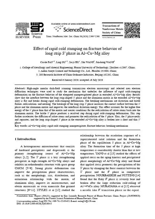
Trans. Nonferrous Met. Soc. China 30(2020) 2590−2598Effect of rapid cold stamping on fracture behavior oflong strip S′ phase in Al −Cu −Mg alloyCai-he FAN 1,2, Ling OU 1,2, Ze-yi HU 1, Shu WANG 3, Jun-hong WANG 31. College of Metallurgy and Material Engineering, Hunan University of Technology, Zhuzhou 412007, China;2. Anhui Jianye Science and Technology Co., Ltd., Huaibei 235000, China;3. 208 Research Institute of China Ordnance Industries, Beijing 102202, ChinaReceived 6 January 2020; accepted 16 July 2020Abstract: High-angle annular dark-field scanning transmission electron microscopy and selected area electron diffraction techniques were used to study the mechanism that underlies the influence of rapid cold-stamping deformation on the fracture behavior of the elongated nanoprecipitated phase in extruded Al −Cu −Mg alloy. Results show that the interface between the long strip-shaped S′ phase and the aluminum matrix in the extruded Al −Cu −Mg alloy is flat and breaks during rapid cold-stamping deformation. The breaking mechanisms are distortion and brittle failure, redissolution, and necking. The breakage of the long strip S′ phase increases the contact surface between the S′ phase and the aluminum matrix and improves the interfacial distortion energy. This effect accounts for the higher free energy of the S′ phase than that of the matrix and creates conditions for the redissolution of solute atoms back into the aluminum matrix. The brittle S′ phase produces a resolved step during rapid cold-stamping deformation. This step further accelerates the diffusion of solute atoms and promotes the redissolution of the S′ phase. Thus, the S′ phase necks and separates, and the long strip-shaped S′ phase in the extruded Al −Cu −Mg alloy is broken into a short and thin S′ phase.Key words: Al −Cu −Mg alloy; rapid cold stamping; nanoprecipitate; fracture behavior; breaking mechanism1 IntroductionA heterogeneous microstructure that consists of hardened precipitates and dispersoids is the primary strengthening source of Al −Cu −Mg alloys [1,2]. The S′ phase is a key strengthening precipitate in high-strength Al −Cu −Mg alloys andexhibits an orthorhombic structure with space groupCMCM [3−6]. Strong plastic deformation can improve the precipitation phase characteristics, such as the morphology, size, distribution, andorientation relationship with the matrix, of aluminum alloy, improve its microstructure, and obtain microscale or even nanoscale fine-grainedstructures [6−11]. STYLES et al [12] studied the relationship between the resolution sequence of a supersaturated solid solution and the formation phase of the equilibrium S phase in Al −Cu −Mg alloy. The formation time of the S phase at high temperature is considerably shorter than that at low temperature. YANG et al [13] studied the effects of applied stress on the aging kinetics and precipitatedphase morphology of Al −Cu −Mg alloy and found that applied stress promotes the precipitation of the S′ phase by changing the force contrast between the S′ phase and the θ′ phase in competitiveprecipitation. NOURBAKHSH and NUTTING [14] found that the flaky θ′ phase is severely bent and broken after the large reduction cold-rolling ofA1−4%Cu alloy. MURAYAMA et al [15] observed a needle-like θ′ transition phase in the equal-Foundation item: Project (19A131) supported by Key Scientific Research Project of Hunan Province, China; Project (2019JJ60050)supported by the Natural Science Foundation of Hunan Province, ChinaCorresponding author:LingOU;Tel:+86-731-22183432;E-mail:****************DOI: 10.1016/S1003-6326(20)65404-8diameter extrusion deformation of A1−Cu alloy, which gradually decomposed into short-chain particles during several equal-angle extrusion processes until it redissolved into the matrix. HUANG et al [16] used cold rolling to change the dislocation cell structure in Al−Cu−Mg alloy with a low Cu/Mg mass ratio and obtained a high-density dispersed fine S′′ phase. ZHAO et al [17] found that the S phase continuously converts to the Ωphase with an increase in cold deformation degree in the cold rolling deformation of 2024 aluminum alloy. ZHANG et al [18,19] studied the effect of multidirectional compressive deformation on the precipitation phase of Al−Cu alloy and found that the precipitation sequence of the supersaturated solid solution formed by the redissolution of the precipitates under strong plastic deformation is related to heating temperature, deformation, and postdeformation grain size.It can be seen that the existing literature is mainly to study the characteristics of the precipitated phase and the re-dissolution phenomenon under the conditions of conventional plastic deformation. There is still a lack of rapid cold punching as the method of plastic deformation, and the impact of the nano-precipitated phase on the microstructure of the alloy is discussed. In order to study the mechanism that underlies the influence of rapid cold-stamping deformation on the fracture behavior of the elongated nanoprecipitated phase in extruded Al−Cu−Mg alloy, this experiment is based on the rapid solidification of fine-grained Al−Cu−Mg alloy billet prepared via spray forming. The fracture behavior of the long strip S′phase in Al−Cu−Mg alloy during rapid cold stamping is also studied. The analysis of the breaking mechanism of the S′phase lays a theoretical foundation for the systematic study of the evolutionary law and strengthening mechanism of the long-shaped S′phase.2 ExperimentalA rapidly solidified fine-grained Al–Cu–Mg alloy cylindrical ingot was prepared on a self-developed SD380 large-scale injection molding apparatus. Table 1 provides the chemical composition of the alloy. The cylindrical ingot was extruded into a d30 mm round bar on a 1250 T extruder at 450 °C with an extrusion ratio of 15:1. The round bar was cut into a small cylinder with dimensions of d30 mm × 20 mm and rapidly cold-stamped for four passes at 25 °C. The sketch maps of rapid cold stamping are presented in Fig. 1. The small cylindrical sample was first placed in the mold, and the first small punch was used to rapidly cold-stamp along the center of the sample to complete the first pass of rapid cold forming. Then, a large-diameter punch was used for cold-stamping along the first pass forming hole, and four passes of rapid cold-stamping were completed in sequence. The parameters of rapid cold stamping are listed in Table 2.Table 1 Composition of alloy studied (wt.%)Cu Mg Mn Si Fe Al3.91 1.63 0.38 <0.03 <0.03 Bal.The samples for microstructure observation were obtained from the center wall of the cylinder fabricated through rapid cold forming. The morphology, size, and distribution of the nanoprecipitated phase of the sample were analyzed through JEM-F200 transmission electronFig. 1 Sketch maps of rapid cold punching (a—Sample; b—Drawing die; c—Punch)Table 2 Technological parameters of rapid cold punching Pass number Diameter/mm Velocity/(mm·s−1) One 10 30Two 14 25Three 20 20Four 27 15 microscopy (TEM). The transmission samples were mechanically prethinned to approximately 80 μm and then subjected to twin-jet electropolishing. The electrolytes were nitric acid and methanol (volume rati o of 1:3) at a temperature of less than −25 °C. The electron microscopy parameters of the high-angle annular dark-field scanning transmission electron microscope (HAADF–STEM) were as follows: acceleration voltage of 200 keV, electron beam half convergence angle of 10 mrad, and beam spot diameter of 0.20 nm.3 Results3.1 As-extruded sampleFigure 2 shows a HAADF−STEM images of the as-extruded Al−Cu−Mg alloy. The elongated S′phase in the as-extruded alloy is regularly distributed in the aluminum matrix; the lengthwise dimension of the elongated S′phase is less than 300 nm, and a number of dislocations are distributed around the precipitated phases (Fig. 2(a)). Figure 2(b) shows the interface between the elongated S′phase and the aluminum matrix observed along the [001]Al direction. The shape of the S′phase is regular, and the interface with the aluminum matrix along the length direction of the S′phase is flat.3.2 Rapid cold punching sampleFigure 3 depicts a HAADF−STEM image of the extruded Al−Cu−Mg alloy after two passes of rapid cold-stamping deformation. The number of S′phases increases drastically, and the S′phases are irregularly distributed in the aluminum matrix. The length of the S′phase after two passes of rapid cold-stamping deformation is the same as that of the extruded sample (Fig. 3(a)). The morphology of most S′phases has changed, and the interface between the S′phase and the aluminum matrix is not flat. The S′phase distorts and breaks during rapid cold-stamping deformation (Fig. 3(b)). The high-magnification field TEM image shows that the long S′phase is broken, the broken interface is visible, and one S′ phase is broken into several parts (A, B, C, and D). Each part undergoes drastic twisting, B is rotated by the α1 angle with respect to A, C is rotated by the α2 angle with respect to B, and D is rotated by the α3angle with respect to C (Fig. 3(c)).Figure 4 shows a HAADF–STEM image of the extruded Al–Cu–Mg alloy after three passes of rapid cold-stamping deformation. As shown in the figure, the number of S′phases in the alloy is reduced significantly compared with those in the specimens after two passes of rapid cold-stamping deformation. However, a large number of short rod- shaped S′ phases are observed, and the S′phasesFig. 2 HAADF−STEM images of S′ precipitates in as-extruded Al−Cu−Mg alloy viewed along [001]Al directionFig. 3HAADF−STEM images of S′precipitates in Al−Cu−Mg alloy undergoing two passes viewed along [001]Al directionremain irregularly distributed in the aluminum matrix (Fig. 4(a)). As the degree of the deformation increases, the morphology of the S′phase changes, the degree of distortion is aggravated, and the broken part of the S′ phase begins to separate from Fig. 4HAADF−STEM images of S′precipitates in Al−Cu−Mg alloy undergoing three passes viewed along [001]Al directionthe base metal (Fig. 4(b)). The high-magnification TEM image shows that the region of the long strip- shaped S′phase is necked, and L1is considerably larger than L2. The ends of necked region tend to separate as the value of L1/L2increases (Fig. 4(c)).Cai-he FAN, et al/Trans. Nonferrous Met. Soc. China 30(2020) 2590−2598 2594Figure 5 shows a HAADF−STEM image of the extruded Al−Cu−Mg alloy after four passes of rapid cold-stamping deformation. This figure shows that the number of S′phases in this sample has increased compared with those in the sample after three passes of rapid cold-stamping deformation.Fig. 5HAADF−STEM images of S′precipitates in Al−Cu−Mg alloy undergoing four passes viewed along [001]Al direction The S′phase is short and thin, and remains irregularly distributed in the aluminum matrix (Fig. 5(a)). After four passes of rapid cold-stamping deformation, the long strip-shaped S′ phases in the extruded sample are nearly broken into short rods, resulting in a considerable reduction in the size of the S′ phase in the aluminum matrix (Fig. 5(b)). The high-magnification field TEM image shows that the necked component of the long strip-shaped S′ phase has disappeared. The ends of the necked region have separated, and the distance between the two parts is L. The S′phase has broken into several independent parts (Fig. 5(c)).4 Analysis and discussion4.1 Breaking mechanism of nano-precipitatedphase during rapid cold stampingIn this experiment, rapid cold stamping deformation has three major characteristics: low deformation temperature (25 °C), large strain, and high strain rate. In accordance with the general criteria of PUGH and related research, the Al2CuMg phase is a typical brittle phase [20,21]. Therefore, combined with the results of this experiment, the breaking mechanisms of the long strip-shaped S′phase in the extruded Al−Cu−Mg alloy induced by rapid cold-stamping deformation are as follows.(1) Distortion and brittle fractureThe long strip-shaped S′phase acts as the major strengthening phase of the extruded Al−Cu−Mg alloy and is regularly distributed in the aluminum matrix, and the S′phase is flat with the aluminum matrix (Fig. 2). During rapid cold stamping deformation, the soft aluminum matrix is subject to severe shear deformation, which causes the hard S′phase to distort under the strong shear deformation force. The torsion angle between parts C and D is α3. When the deformation force reaches a certain level, i.e., when the torsion angle reaches a certain value (e.g. α1 or α2), brittle S′ phase fractures and interfaces are formed between A and B or B and C (Fig. 3(c)). With the distortion and brittle fracture of the long strip-shaped S′phase, the drastic increase in brittle interfaces considerably increases the contact surface between the precipitated phase and the aluminum matrix. The interfacial distortion energy between the precipitated phase and the aluminum matrix is improved, and diffusionconditions for the solute atoms are created. TheCai-he FAN, et al/Trans. Nonferrous Met. Soc. China 30(2020) 2590−2598 2595redissolution of the S′ phase during rapid cold-stamping deformation accelerates. The distortion and brittle fracture model of the long strip-shaped S′ phase is shown in Fig. 6.(2) Resolving and neckingFigure 7 presents a HAADF–STEM image showing the resolved step of the S′ phase and a model of redissolution and necking in the sample subjected to three passes of rapid cold stamping. The resolved step is clearly observable in the S′ phase, and the arrows in the figure are the resolving direction. The resolved step is the product of the twisting and brittle fracture of the S′ phase during strong plastic deformation. Given that the distortion and breakage of the long S′ phase considerably improve the interfacial distortion energy between the S′ phase and the aluminum matrix, the solute atoms located at the region of the S′ phase with high distortion energy are highly likely to be redissolved. The local accelerated redissolution of the S′ phase results in a significant reduction in the size of the S′ phase in this region, i.e., the formation of a neck (Fig. 4(c)), which further increases the interfacial distortion between the precipitated phase and the aluminum matrix and can accelerate redissolution at the necked position. Necking disappears when the value of L 1/L 2 is infinite, and the disappearance of the neck causes the separation of the two parts of the precipitated phase (Fig. 5(c)).The presence of high numbers of resolved steps in the S′ phase is associated with the large contact surface of the broken particles within the aluminum matrix. The diffusion of solute atoms is facilitated. In accordance with the classical thermodynamic view [22], a certain equilibrium vacancy concentration in the crystal exists at anyFig. 6 Distortion and brittle fracture model of long strip-shaped S′ phase: (a) As-extruded; (b) Two-passFig. 7 HAADF −STEM image (a) and necking model (b) of precipitated phase in Al −Cu −Mg alloy undergoing three passestemperature and changes positions continuously. The existence and movement of vacancies create conditions for atomic diffusion. The dislocation density increases significantly during rapid cold deformation. Dislocations will generate a large number of vacancies in the matrix during delivery and movement, and each time, a rapid cold shear deformation will produce a large number of new vacancies. Simultaneously, the long strip-shaped S′phase is constantly twisted and broken during rapid cold-stamping deformation, and the contact interfaces between S′phase and aluminum matrix increase and are accompanied by a large number of vacancies. The number of vacancies undergoing strong deformation increases sharply [19,23], the diffusion rate of solute atoms can be increased by five orders of magnitude, and volume diffusion can be increased by eight orders of magnitude. The alloy was prepared through spray-forming rapid solidification technology and had fine grains and uniform structure. The average grain size was app roximately 5 μm. During rapid cold-stamping deformation, the grains are further refined into nanoscale, and thus, the grain boundary area increases. It also provides an atomic diffusion channel for the redissolution of the precipitated phase, and this channel considerably promotes the redissolution of the precipitated phase.4.2 Fracture mechanism of nano-precipitatedphase during rapid cold stampingUnder the condition of rapid cold-stamping deformation, the long strip-shaped S′phase in the extruded Al−Cu−Mg alloy undergoes intense distortion, brittle fracture, redissolution, necking, and separation (Figs. 3−5). Consequently, the long strips of S′ phases transform into short rods or even redissolve and disappear. In contrast with that of the extruded sample, the brittle fracture of the long strip S′ phase remarkably increases the contact surface of the S′ phase and the matrix, and interface distortion can be drastically improved. This phenomenon results in the free energy of the S′phase being higher than that of the matrix. The disturbance of the energy balance between the reprecipitated phase and the matrix creates conditions for the redissolution of the solute atoms into the matrix. The binding energy (E coh) and the formation enthalpy of ∆H[20,21] between the Al2Cu and Al2CuMg phases are calculated using the first principle equations:AB A Bcoh total A atom A atom[(1)]E E x E x E=−+− (1)AB A Btotal A solid A solid[(1)]H E x E x E∆=−+− (2)where ABtotalE is the average energy per atom ofeach intermetallic compound; AatomE and BatomE are the energy of free atoms A and B, respectively;AsolidE and BsolidE are the average energy per atom in stable elemental A and B, respectively; x A represents the mole fraction of atom A in the compound.V ASILS et al [24] believed that two types of processes will occur when precipitates are completely dissolved into the matrix. The first process is lattice transformation, wherein the lattice of the precipitated phase changes into the matrix lattice. The second process is the diffusion of the redissolved solute atoms in the matrix; this phenomenon increases the uniformity of the supersaturated solid solution. The results show that the S′ phase in the as-extruded alloy redissolves into the aluminum matrix after three passes of rapid cold-stamping deformation and becomes refined. The rapid cold-stamping deformation temperature of the alloy in this test is low, and if solute atoms uniformly disperse into the matrix by diffusion to redissolve the precipitate phase, the redissolution rate must be extremely slow.In accordance with the solid-state phase transition theory [22], the critical size of the nucleus (r c) is expressed as follows:cr f UGσ=−∆(3)where σis the surface free enthalpy, ∆G is the difference in volume free enthalpy between the parent phase and the precipitated phase, and U is the strain energy produced by the two phases. With the fragmentation of the precipitated phase, σ, ∆G, and U change significantly, resulting in an increase in the critical size (r c) of the precipitated phase. The redissolution amount and rate of the precipitated phase increase.In summary, the redissolution of nano- precipitates during strong plastic deformation plays an important role in structural evolution. The distortion and brittle fracture of the S′ phase during rapid cold-stamping deformation results in a resolved step, which accelerates the redissolution ofCai-he FAN, et al/Trans. Nonferrous Met. Soc. China 30(2020) 2590−2598 2597the S′ phase. The partial redissolution of the phase promotes the further necking of the S′phase and results in the separation of various parts of the S′phase, resulting in the fragmentation of the elongated S′phase in the extruded alloy and its transformation into a short and thin S′ phase.5 Conclusions(1) The interface between the strip-shaped S′phase and the aluminum matrix in the extrudedAl−Cu−Mg alloy is flat and breaks during rapid cold-stamping deformation. The fracture mechanisms are distortion, brittle fracture, redissolution, and necking.(2) The brittle fracture of the long S′phase increases the contact surface between the S′phase and the aluminum matrix, improves the interfacial distortion energy, and accounts for the higher free energy of the S′ phase than that of the matrix. The disturbance of the energy balance between the S′phase and the matrix creates diffusion conditions for the redissolution of the solute atoms into the matrix.(3) The redissolution of nanoprecipitates during strong plastic deformation plays an important role in structural evolution. The break of the local S′phase accelerates its redissolution, resulting in the fragmentation of long S′phase into short and thin S′phase.References[1]CHENG S, ZHAO Y H, ZHU Y T, MA E. Optimizing thestrength and ductility of fine structured 2024Al alloy bynano-precipitation [J]. Acta Mater, 2007, 55(17): 5822−5832. [2]WANG Jian-qiu, ZHANG Bo, WU Bo, MA Xiu-liang.Size-dependent role of S phase in pitting initiation of 2024 Alalloy [J]. Corrosion Science, 2016, 105(2): 183−189.[3]WANG S C, STARINK M J. Two types of S phaseprecipitates in Al−Cu−Mg alloys [J]. Acta Materialia, 2007,55(3): 933−941.[4]LIU Zi-ran, CHEN Jiang-hua, W ANG Shuang-bao, YUANDing-wang, YIN Mei-jie, WU Cui-lan. The structure and theproperties of S-phase in AlCuMg alloys [J]. Acta Materialia,2011, 59(19): 7396−7405.[5]KILAAS R, RADMILOVIC V. Structure determination andstructure refinement of Al2CuMg precipitates by quantitativehigh-resolution electron microscopy [J]. Ultramicroscopy,2001, 88(1): 63−72.[6]WANG Jian-qiu, ZHANG Bo, ZHOU Yang-tao, MAXiu-liang. Multiple twins of a decagonal approximantembedded in S-Al2CuMg phase resulting in pitting initiationof 2024Al alloy [J]. Acta Materialia, 2015, 82(1): 22−31. [7]KANG S B, LIM C Y, KIM H W, MAO J F. Microstructureevolution and hardening behavior of 2024 aluminum alloyprocessed by the severe plastic deformation [J]. MaterialsScience Forum, 2002, 396−402(2):1163−1168.[8]YANG Bing, MA Xiu-liang. Local decomposition inducedby dislocations inside θ′precipitates in Al−Cu alloy [J].Journal of Chinese Electron Microscopy Society, 2013, 32(4):289−294. (in Chinese)[9]WANG Shuang-bao, CHEN Jiang-hua, YIN Mei-jie, LIUZi-ran, YUAN Ding-wang. Double atomic wall based dynamic precipitates of the early-stage S-phase in AlCuMgalloys[J]. Acta Materialia, 2012, 60(19): 6573−6580.[10]AN Li-hui, CAI Yang, LIU Wei, YUAN Shi-jian, ZHUShi-qiang, MENG Fan-cheng. Effect of pre-deformation onmicrostructure and mechanical properties of 2219 aluminumalloy sheet by thermomechanical treatment [J]. Transactionsof Nonferrous Metals Society of China, 2012, 22(2): 370−375.[11]YIN Mei-jie, CHEN Jiang-hua, WANG Shuang-bao, LIUZi-ran, CHA Li-mei. Anisotropic and temperature-dependentgrowth mechanism of S-phase precipitates in Al−Cu−Mgalloy in relation with GPB zones [J]. Transactions ofNonferrous Metals Society of China, 2016, 26(1): 1−11.[12]STYLES M J, MARCEAU R K W, BASTOW T J, BRANDH E A, GIBSON M A, HUTCHINSON C R. Thecompetition between metastable and equilibrium S(Al2CuMg)phase during the decomposition of Al−Cu−Mg alloys[J].Acta Materialia, 2015, 98(1): 64−80.[13]YANG Pei-yong, ZHENG Zi-qiao, XU Fu-shun, LI Shi-chen,LI Jian, ZHOU Ming. Effect of external stress on kinetics ofprecipitation and morphologies of precipitates in Al−Cu−Mgalloy with high Cu/Mg ratio [J]. Chinese Journal of RareMetals, 2006, 30(3): 324−328. (in Chinese)[14]NOURBAKHSH S, NUTTING J. The high straindeformation of an aluminium−4%copper alloy in the supersaturated and aged conditions [J]. Acta Metallurgica,1980, 28(3): 357−365.[15]MURAYAMA M, HORITA Z, HONO K. Microstructure oftwo-phase Al−1.7at%Cu alloy deformed by equal-channelangular pressing [J]. Acta Mater, 2001, 49(1): 2l−29.[16]HUANG Yu-jin, CHEN Zhi-guo, ZHENG Zhi-qiao. Aconventional thermo-mechanical process of Al−Cu−Mg alloyfor increasing ductility while maintaining high strength [J].Scripta Materialia, 2011, 64(5): 382−385.[17]ZHAO Yun-long, YANG Zhi-qing, ZHANG Zhen-jun, SUGuo-yue, MA Xiu-liang. Double-peak age strengthening ofcold-worked 2024 aluminum alloy[J]. Acta Materialia, 2013,61(5): 1624−1638.[18]ZHANG Zi-zhao, XU Xiao-chang, HU Nan, QU Xiao,CHEN Zhen-xiang. Re-ageing behavior of Al−Cu alloy afterre-dissolution of precipitated phases caused by severe plasticdeformation[J]. Journal of Central South University (Scienceand Technology), 2010, 41(5): 1782−1790. (in Chinese) [19]ZHANG Zi-zhao, XU Xiao-chang, LIU Zhi-yi, XIAQing-kun, ZENG Su-min. Re-precipitate behavior of supersaturated solid solution of Al−Cu alloy caused bysevere plastic deformation during subsequent deformation [J].The Chinese Journal of Nonferrous Metals, 2009, 19(11):Cai-he FAN, et al/Trans. Nonferrous Met. Soc. China 30(2020) 2590−2598 25981962−1968. (in Chinese)[20]PUGH S F. Relations between the elastic moduli and theplastic properties of polycrystalline pure metals [J].Philosophical Magazine, 1954, 45(367): 823−843.[21]ZHANG Jian, HUANG Ya-ni, MAO Cong. Structural, elasticand electronic properties of θ(Al2Cu) and S(Al2CuMg)strengthening precipitates in Al−Cu−Mg series alloys: First-principles calculations [J]. Solid State Communications, 2012, 152(23): 2100−2104.[22]LIAO Fei, FAN Shi-tong, DENG Yun-lai, ZHANG Jin.First-principle calculations of mechanical properties of Al2Cu, Al2CuMg and MgZn2 intermetallics in high strengthAluminum alloys [J]. Journal of Aeronautical Materials, 2016, 36(6): 1−8. (in Chinese)[23]YU Yong-ling. Principles of metallography [M]. 2nd ed.Beijing: Metallurgical Industry Press, 2013. (in Chinese) [24]V ASILS L S, LONMAEV I L, ELSUKOV E P. On theanalysis of the mechanisms of the strain-induced dissolutionof phases in metals [J]. Physics of Metals and Metallography,2006, 102(2): 186−197.快速冷冲对Al−Cu−Mg合金长片状S′相破断行为的影响范才河1,2,欧玲1,2,胡泽艺1,王舒3,王俊红31. 湖南工业大学冶金与材料工程学院,株洲412007;2. 安徽建业科技有限公司,淮北235000;3. 中国兵器工业第二○八研究所,北京102202摘要:采用高角度环形暗场(HAADF)扫描透射电子显微镜(STEM)和选区电子衍射(SAED)技术,研究快速冷冲强变形对挤压态Al−Cu−Mg合金长片状纳米析出相破断行为的影响机理。
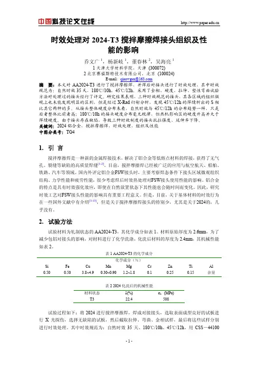
时效处理对2024-T3搅拌摩擦焊接头组织及性能的影响乔文广1,杨新岐1,董春林2,吴海亮11天津大学材料学院,天津 (300072)2北京赛福斯特技术有限公司,北京 (100024)E-mail:qiaowgsx@摘要:本文对AA2024-T3进行了搅拌摩擦焊,并焊后对接头进行了时效处理,其中时效℃,45/12h℃。
采用了金相、硬度、拉伸、塑性弯曲试验规范为:自然时效35天,180/10h方法对处理过的接头经行了评定。
研究结果表明,三种时效规范的接头,其各区域的组织微℃的焊缝析出的S相观上也未能发现明显的区别,但是经过X-Rad衍射分析,发现45/12h℃的分布趋势一样,只是比其它两种的多。
从接头整体硬度分布来看,自然时效与45/12h℃的接头硬度分布毫无规律,但热机影响区的硬度升高并大于后者整体比前者高;180/10h焊缝硬度。
由于接头存在缺陷,导致三种时效制度的接头抗拉强度、延伸率下降。
关键词:2024铝合金,搅拌摩擦焊,时效处理,组织及性能中图分类号:TG41.引言搅拌摩擦焊是一种新的金属焊接技术,解决了铝合金等低熔点材料的焊接,获得了无气孔、裂缝等缺陷的高质量焊缝[1-2]。
目前,搅拌摩擦焊已经被广泛的应用与航空航天、船舶、铁路、汽车等领域。
国内外评定铝合金FSW接头时,主要考察焊态条件下接头区域微观组织结构、力学性能和疲劳性能,很少考虑焊后时效热处理对FSW接头使用性能的影响。
铝合金的特点是具有时效强化效应,即使在自然放置状态下其性能也会随时间而变化。
因此,研究时效工艺对FSW接头性能的影响具有重要工程意义。
但是,目前,关于基体材料的时效行为在一些国外文献中有介绍[3-13],但是关于搅拌摩擦焊接头的特别少,尤其是关于2024的,几乎没有。
2.试验方法试验材料为轧制状态的AA2024-T3,其化学成分如表1。
材料原始厚度为2.6mm,为了减少包铝对接头的影响,对材料进行了化学洗涤,化洗后材料的厚度为2.4mm,其机械性能如表2。
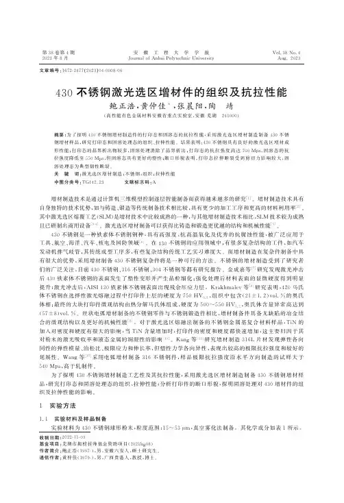
第38卷第4期2023年8月安 徽 工 程 大 学 学 报J o u r n a l o fA n h u i P o l y t e c h n i cU n i v e r s i t y V o l .38N o .4A u g.2023文章编号:1672-2477(2023)04-0008-06收稿日期:2022-11-03 基金项目:芜湖市揭榜挂帅基金资助项目(2021h g 08)作者简介:鲍正浩(1997-),男,安徽六安人,硕士研究生㊂通信作者:黄仲佳(1979-),男,广西贵港人,教授,博士㊂430不锈钢激光选区增材件的组织及抗拉性能鲍正浩,黄仲佳*,张晨阳,陶 靖(高性能有色金属材料安徽省重点实验室,安徽芜湖 241000)摘要:为了探明430不锈钢增材制造件的打印态和固溶态的抗拉性能,采用激光选区增材制造制备430不锈钢增材样品,研究打印态和固溶处理态的组织㊁拉伸性能㊂结果表明:430不锈钢具有良好的激光选区增材成形性能;打印态的晶界析出物较多,固溶处理消除了晶界析出;打印态的抗拉强度高达700M p a ,固溶态的抗拉强度降低至550M p a ,但固溶态具有更好的塑性;断口形貌表明,打印态拉伸断裂受到剪切力影响较大,固溶处理态为典型韧性断裂㊂关 键 词:激光选区增材制造;不锈钢;组织;拉伸性能中图分类号:T G 142.23 文献标志码:A 增材制造技术是通过计算机三维模型控制逐层智能制备而获得越来越多的研究[1]㊂增材制造技术具有自身独特的技术优势,如与铸造㊁锻造等传统制备技术相比较,具有更少的加工工序和更高的材料利用率[2]㊂其中激光选区熔覆工艺(S L M )是增材技术中比较成熟的一种,与其他增材制造技术相比,S L M 技术较为成熟且已研制出商用设备[3-4]㊂激光选区增材制备可以获得比铸造和锻造更优越的结构和机械性能[5]㊂430不锈钢是一种铁素体不锈钢钢种,具有高强度㊁抗高温氧化及优秀的抗腐蚀性能,被广泛应用于工具㊁航空㊁海洋㊁汽车㊁核电及国防领域[6]㊂在430不锈钢的应用领域中,有很多复杂结构的工件,如汽车发动机排气歧管,其传统成型工序多,有些复杂结构传统工艺实习难度大㊂而增材制造在复杂件制备中具有很大的优势,采用增材制备430不锈钢复杂件将是一种可行的方法㊂不锈钢的增材制造受到了研究者们的广泛关注,目前430不锈钢㊁316不锈钢㊁304不锈钢等都有研究报告㊂金成嘉等[7]研究发现激光冲击后430铁素体不锈钢的表面发生了塑性变形并产生晶粒细化;强化处理后材料表面的显微硬度得到明显提升;激光冲击后,A I S I 430铁素体不锈钢表面出现残余压应力层㊂K r a k h m a l e v 等[8]研究表明,420马氏体不锈钢在选择性激光熔融过程中打印件上层的硬度为750H V 0.2,组织中包含(21±1.2)v o l .%的奥氏体相;最终的大块打印件微观结构由热分解马氏体组成,硬度为500~550H V 0.2,奥氏体含量异常高达到(57±8)v o l .%㊂丝状电弧增材制备的不锈钢零件与不锈钢锻造件相比,增材制备件具备无缺陷的冶金结合的微观结构以及更好的机械性能[9]㊂对于激光选区熔融法制备的不锈钢金属基复合材料样品,T i N 的加入对密度和硬度有很大的影响,当T i N 含量增加时,打印件的密度和硬度都快速增加,这主要归因于其对粉末的激光吸收率和液态金属的润湿性的影响[10]㊂K a n g 等[11]研究增材制造316L 片材发现弹性各向同性的弹性模量㊁泊松比㊁极限应力和伸长率,但塑性力学各向异性,表现出较高的极限抗拉强度和较好的延展性㊂W a n g 等[12]采用电弧增材制备316不锈钢件,样品极限抗拉强度沿水平方向制造的试样大于540M p a ,高于轧制件㊂为了探明430不锈钢增材制造工艺性及其抗拉性能,采用激光选区增材制造制备430不锈钢增材样品,研究打印态和固溶处理态的组织㊁拉伸性能;分析打印件的断口形貌,探明固溶处理对430增材件的组织及拉伸性能的影响㊂1 实验方法1.1 实验材料及样品制备实验材料为430不锈钢球形粉末,粒度范围:15~53μm ,真空雾化法制备㊂其化学成分如表1所示㊂表1 430不锈钢粉末化学成分(质量分数,%)元素C r M n N i S i C O S P F e 含量16.000~18.000≤1.000≤0.600≤0.750≤0.120≤0.039≤0.030≤0.040余量在打印制备样品之前,使用烘箱进行不锈钢粉末烘干,烘干温度为100℃,时间为2h ㊂再使用S L M 125金属3D 打印机制备尺寸为100mm×50mm×20mm 不锈钢金属块,打印工艺参数主要调整激光功率(P )㊁扫描速度(v )㊁层厚(t )及扫描间距(h ),层间转角固定选用35°及扫描方式为条带扫描㊂打印样品的固溶热处理实验在真空/气氛管式电炉中进行,设备型号为S X 2-4-10A ㊂固溶处理工艺为:860℃保温20m i n ,水冷至室温㊂ 图1 拉伸试样示意图1.2 样品检测及表征采用洛氏硬度计测量样品的硬度;采用万能拉伸实验机进行拉伸实验,检测打印件的力学性能,拉伸试样示意图如图1所示㊂采用光学显微镜㊁扫描电镜S E M (型号E M -30A X )进行微观组织形貌和断口形貌分析㊂2 结果和讨论2.1 增材制备工艺参数对空隙率的影响打印工艺参数及样品的密度如表2所示㊂由表2可以看到,打印工艺参数扫描速度(v )㊁激光功率(P )㊁层厚(t )和扫描间距(h )变化对密度均有影响㊂提高激光功率和适当降低速度均可以提高打印件的致密性,但考虑到打印效率问题,应尽快提高打印速度㊂表2 打印工艺参数及样品的密度序号激光功率/W 扫描速度/(mm /s )扫描间距/μm 层厚/μm 密度/%1300900110509623001025110509533309001105098序号激光功率/W 扫描速度/(mm /s )扫描间距/μm 层厚/μm 密度/%43301025110509753509001105099635010251105098探究不同工艺参数对打印件的影响,430不锈钢打印件的气孔分布形貌如图2所示㊂图2a 对应激光功率350W 和扫描速度900mm /s 的工艺(见表2中的第5组工艺),由图2a 可知,气孔较少,这也是该工艺致密度高的另一种表现㊂图2b 对应激光功率350W 和扫描速度1025mm /s 的工艺(见表2中的第6组工艺),图2b 的气孔率比图2a 有所增加㊂图2c 对应激光功率330W 和扫描速度900mm /s 的工艺(见表2中的第3组工艺),图2c 的气孔率与图2b 相当㊂图2d 对应激光功率330W 和扫描速度1025mm /s 的工艺(见表2中的第4组工艺),与图2c 相比,气孔率又进一步增加㊂图2e 对应激光功率300W 和扫描速度900mm /s 的工艺(见表2中的第1组工艺),气孔率也有所增加㊂图2f 对应激光功率300W 和扫描速度1025mm /s 的工艺(见表2中的第2组工艺),气孔率达到最高㊂由图2可知,随着激光功率增加和扫描速度降低,气孔率呈逐步降低的趋势㊂除了打印工艺之外,气孔的形成还受到粉末表面的水分及粉末中残留气体的影响[13],因此气孔率也不会与致密度成正比增加㊂较高的激光功率或者较低的激光扫描速度致使了较高的熔池温度,利于粉末完全熔化获得较为致密的打印件㊂此外,低熔点合金元素的蒸发也可以形成气孔,熔池的高凝固速率导致低熔点元素的蒸发无法有足够的时间从熔池逸出,因此只能存留在熔池内形成气孔[14],气孔在制件中随机分布,很难完全消除㊂综上,430不锈钢的打印工艺中,表2中的第5组工艺参数打印出来的样块,气孔最少且密度最高,因此,提高功率,降低扫描速度,打印件成形更好㊂2.2 打印态和固溶处理态的组织分析430不锈钢增材件底面(即激光扫描面)打印态和固溶处理态的光学显微组织如图3所示㊂由图3a 可见,430不锈钢激光熔融打印态的组织较细小,激光熔融的道与道之间的熔化线清晰可见;由图3b 可见,其固溶处理态的组织经过固溶处理,光学显微组织尺寸㊁形貌等没有明显变化㊂430不锈钢增材件扫描面打印态及固溶处理态的扫描电镜形貌图如图4所示㊂打印态在晶界处析出相较多,在图中显示为白色相分布,由图4a ㊁b 可见,这些晶界处的白色相是富铬的脆性相[15],会导致不锈㊃9㊃第4期鲍正浩,等:430不锈钢激光选区增材件的组织及抗拉性能㊃01㊃安 徽 工 程 大 学 学 报第38卷钢件的塑性降低㊂由图4c㊁d可见,经过固溶处理,430不锈钢增材件的晶界析出已经融入固溶体中,晶界的析出相几乎看不到㊂此外,对比图4b㊁d可知,相组织的尺寸也变大,说明固溶处理使得430打印件的相相应增加且晶界处的析出相融入固溶体中㊂图2 430不锈钢打印件的气孔分布形貌图3 430不锈钢增材件底面的光学显微组织430不锈钢增材件侧面的打印态及固溶处理态的形貌图如图5所示㊂由图5a㊁b可见,增材件侧面的打印态组织为鱼鳞状微观组织,图5a上的鱼鳞状结构特点说明大量金属颗粒经过激光轰击熔化后,处在短暂熔融状态的金属小液滴在重力作用下有向下滴落的运动趋势,其迅速凝固后,保留了这一特点,所以每一熔积层结构的下端会有近圆形的形貌呈现出来,凝固后的试样组织存在明显的各向异性,形成了类似鱼鳞状的组织形态,这是典型激光选区熔融打印态的组织㊂经固溶时效热处理可以看出,鱼鳞形状组织的边界形貌有所改变,鱼鳞状变得不明显,这是固溶处理过程中,组织重结晶导致组织形貌发生变化形成的㊂2.3 增材制造件的拉伸性能430不锈钢的S L M打印件的拉伸曲线如图6所示,图6中虚线曲线为打印态的拉伸曲线㊂由图6可知,打印态的抗拉强度达到700M p a,没有出现明显的屈服现象㊂图6中实线曲线为固溶处理态的拉伸曲线,固溶态具有明显的屈服现象;固溶态的抗拉强度比打印态有所降低,抗拉强度大约550M p a,固溶处理态比打印态具有更大的延伸率,表明固溶态具有更优良的塑性㊂打印态的强度高是由于S L M成形过程中形成的具有较高的位错密度的细小胞状组织结构使得打印件的强度指标提高[16-18];此外,打印态的晶界析出相也会提高不锈钢的拉伸强度,降低塑性[19];固溶处理有效消除了高位错密度,因此固溶态比打印态的抗拉强度有所降低㊂打印态拉伸断口形貌如图7所示㊂由图7a可见,打印态断口的低倍数的宏观断口形貌呈灰暗,剪切断裂的斜度较大,断裂的宏观表面有部分垂直于最大正应力方向,也有平行于切应力方向的,故正断和切图4 430不锈钢增材件底面扫描电镜形貌图图5 430不锈钢增材件侧面组织形貌图 图6 增材制造件的拉伸曲线断都有;高倍断口形貌呈暗灰色纤维状,由图7b ㊁c 可知,高倍断口形貌具有韧性断裂特征,故可认定为韧性断裂㊂增材件固溶处理态的断口形貌如图8所示㊂由图8a 断口宏观形貌可知,断口较为平齐,没有剪切断裂特征;图8b ~d 为断口的高倍扫描形貌图,断口表面有许多小韧窝,是典型的韧性断裂形貌㊂可见与打印态相比较,固溶处理态降低了样品的抗拉强度,提高了塑性㊂3 结论430不锈钢具有良好激光选区增材制造成型性能,打印工艺参数直接影响打印件的致密度和气孔率,当打印㊃11㊃第4期鲍正浩,等:430不锈钢激光选区增材件的组织及抗拉性能㊃21㊃安 徽 工 程 大 学 学 报第38卷图7 430不锈钢增材制造件的打印态断口形貌图8 430增材制造件的固溶热处理态的断口形貌的激光功率为350W,扫描速度为900mm/s,扫描间距为110mm和层厚为50mm时,打印件获得较高的致密度及较低的气孔率㊂打印态的晶界析出物明显,固溶处理消除了晶界析出;打印态的抗拉强度高达700M p a,固溶态的抗拉强度降低至550M p a,但具有更好的塑性;打印态样品的断裂受到剪切的影响较大,固溶处理态为典型韧性断裂㊂参考文献:[1] 熊华平,郭绍庆,刘伟,等.航空金属材料增材制造技术[M].北京:航空工业出版社,2019.[2] K R U T HJP,F R O Y E N L,V A E R E N B E R G H JV,e t a l.S e l e c t i v e l a s e rm e l t i n g o f i r o n-b a s e d p o w d e r[J].J o u r n a l o fm a t e r i a l s p r o c e s s i n g t e c h n o l o g y,2004,149(1):616-622.[3] G U DD,Z HA N G H M,C H E N H Y,e t a l.L a s e r a d d i t i v em a n u f a c t u r i n g o f h i g h-p e r f o r m a n c em e t a l l i c a e r o s p a c e c o m-p o n e n t s[J].C h i n e s e j o u r n a l o f l a s e r s,2020,47(5):0500002.[4] Z HA N GJL,L IFL,Z HA N G HJ.R e s e a r c h p r o g r e s so n p r e p a r a t i o no fm e t a l l i cm a t e r a l sb y s e l e c t i v e l a s e rm e l t i n g[J].L a s e r a n do p t o e l e c t r o n i c s p r o g r e s s,2019,56(10):100003.[5] S I L V A T,S I L V AF,X A V I E RJ,e t a l.M e c h a n i c a l b e h a v i o u r o fm a r a g i n g s t e e l p r o d u c e d b y S L M[J].P r o c e d i a s t r u c t u r-a l i n t e g r i t y,2021,34:45-50.[6] V I G N E S HWA R A N S,MA D HA V A N R,Y O G A N J A N E Y U L U G,e ta l.S t u d y o nf o r m i n g a n df r a c t u r eb e h a v i o ro fc o n t i n u o u s a n n e a l e d,b a t c h a n n e a l ed a n d c o l d r o l le dS S430s h e e tm e t a l s[J].M a t e r i a l s t o d a y:p r o c e e d i n g s,2021,46:51-60.[7] 金成嘉.激光冲击强化A I S I430铁素体不锈钢抗腐蚀性能研究[D].镇江:江苏大学,2019.[8] K R A K HMA L E VP,Y A D R O I T S A V AI,F R E D R I K S S O NG,e t a l.I n s i t uh e a t t r e a t m e n t i n s e l e c t i v e l a s e rm e l t e dm a r-t e n s i t i cA I S I420s t a i n l e s s s t e e l s[J].M a t e r i a l s a n dd e s i g n,2015,87:380-385.[9] G HA F F A R IM ,N E MA N IA V ,N A S I R IA.I n t e r f a c i a l b o n d i n g b e t w e e n aw i r e a r c a d d i t i v em a n u f a c t u r e d 420m a r t e n s i -t i c s t a i n l e s s s t e e l p a r t a n d i t sw r o u g h t b a s e p l a t e [J ].M a t e r i a l s c h e m i s t r y a n d p h y s i c s ,2020,251:123199.[10]Z HA O X ,W E IQS ,G A O N ,e t a l .R a p i d f a b r i c a t i o n o fT i N /A I S I 420s t a i n l e s s s t e e l c o m p o s i t e b y s e l e c t i v e l a s e rm e l t -i n g a d d i t i v em a n u f a c t u r i n g [J ].J o u r n a l o fm a t e r i a l s p r o c e s s i n g t e c h n o l o g y ,2019,270:8-19.[11]K A N GL ,C H E N F ,WU B ,e t a l ,M e c h a n i c a l p r o p e r t i e sa n d m i c r o s t r u c t u r eo f l a s e r -c l ad d i n g a d d i t i ve l y m a n uf a c t u r e d 316Ls t a i n l e s s s t e e l s h e e t s [J ].J o u r n a l o f c o n s t r u c t i o n a l s t e e l r e s e a r c h ,2022,199:107603.[12]WA N GLL ,X U EJX ,WA N GQ.C o r r e l a t i o nb e t w e e n a r cm o d e ,m i c r o s t r u c t u r e ,a n dm e c h a n i c a l p r o p e r t i e s d u r i ng wi r e a r c a d d i t i v em a n u f a c t u r i n g o f 316Ls t a i n l e s s s t e e l [J ].M a t e r i a l s s c i e n c e a n de n g i n e e r i n g A ,2019,751:183-190.[13]C A R T E RL N ,WA N G X ,R E A D N ,e t a l .P r o c e s so p t i m i s a t i o no f s e l e c t i v e l a s e rm e l t i n g u s i n g e n e r g y d e n s i t y mo d e l f o r n i c k e l b a s e d s u p e r a l l o y s [J ].M a t e r i a l s s c i e n c e a n d t e c h n o l o g y A ,2016,32:657-661.[14]Y A N G K V ,R OM E T S C H P ,J A R V I ST ,e t a l .P o r o s i t y f o r m a t i o nm e c h a n i s m s a n d f a t i g u e r e s p o n s e i na l -s i -m g a l l o y s m a d eb y s e l e c t i v e l a s e rm e l t i n g [J ].M a t e r i a l s s c i e n c e&e n g i n e e r i n g A ,2018,712:166-174.[15]赵才宇.441不锈钢焊接接头组织及力学性能研究[D ].长春:吉林大学,2022.[16]G R A Y G T ,L I V E S C U V ,R I G G P A ,e ta l .S t r u c t u r e /p r o p e r t y (c o n s t i t u t i v ea n ds p a l l a t i o nr e s p o n s e )o fa d d i t i v e l ym a n u f a c t u r e d316Ls t a i n l e s s s t e e l [J ].A c t am a t e r i a l i a ,2017,138:140-149.[17]C A S A T IR ,L E MK EJ ,V E D A N IM.M i c r o s t r u c t u r ea n df r a c t u r eb e h a v i o ro f 316La u s t e n i t i cs t a i n l e s ss t e e l p r o d u c e db y s e l ec t i v e l a s e rm e l t i n g [J ].J o u r n a l o fm a t e r i a l s s c i e n c e a nd te c h n o l o g y ,2016,32(8):738-744.[18]S A L M A N O O ,G A MM E RC ,C H A U B E YAK ,e t a l .Ef f e c t o f h e a t t r e a t m e n t o nm i c r o s t r u c t u r e a n dm e c h a n i c a l p r o pe r t i e s of 316Ls t e e l s y n t h e s i z e db y s e l e c t i v e l a s e rm e l t i ng [J ].M a t e r i a l s s c i e n c e&e n g i n e e r i n g A ,2019,748:205-212.[19]R O YS ,S I L WA LB ,N Y C ZA ,e t a l .I n v e s t i g a t i n g th e e f f e c t o f di f f e r e n t s h i e l d i n gga sm i x t u r e so n m i c r o s t r u c t u r e a n d m e c h a n i c a l p r o p e r t i e s o f 410s t a i n l e s s s t e e l f ab r ic a t e dv i a l a r g e s c a l e ad d i t i v em a n u f a c t u r i n g [J ].A d d i t i v em a n u f a c t u r -i n g ,2021,38:101821.M i c r o s t r u c t u r e a n dT e n s i l eP r o p e r t i e s o f 430S t a i n l e s s S t e e l F a b r i c a t e db y L a s e r S e l e c t e dA d d i t i v eM a n u f a c t u r i n gB A OZ h e n g h a o ,HU A N GZ h o n g J i a *,Z H A N GC h e n y a n g ,T A OJ i n g(A n h u iK e y L a b o r a t o r y o fH i g h -P e r f o r m a n c eN o n -f e r r o u sM e t a lM a t e r i a l s ,W u h u241000,C h i n a )A b s t r a c t :I no r d e r t o i n v e s t i g a t e t h e t e n s i l e p r o p e r t i e so f 430s t a i n l e s s s t e e l p a r t s f a b r i c a t e db y a d d i t i v e m a n u f a c t u r i n g i n p r i n t e d a n d s o l i d s o l u t i o n s t a t e ,t h e 430s t a i n l e s s s t e e l s a m p l e sw e r e p r e p a r e db y l a s e r s e l e c t i v e a d d i t i v em a n u f a c t u r i n g ,t h e n t h em i c r o s t r u c t u r e a n d t e n s i l e p r o p e r t i e s o f a s p r i n t e d a n d a s s o l u -t i o n t r e a t e dw e r e i n v e s t i g a t e d .T h e r e s u l t s s h o wt h a t 430s t a i n l e s s s t e e l h a s g o o d f o r m a b i l i t y o f l a s e r s e -l e c t i v e a d d i t i v em a n u f a c t u r i n g .T h e r ea r em a n yg r a i nb o u n d a r yp r e c i p i t a t e s i nt h e p r i n t e ds a m p l e s ,a n d g r a i nb o u n d a r yp r e c i p i t a t e s h a v e b e e n e l i m i n a t e db y s o l i d s o l u t i o n t r e a t m e n t .T h e t e n s i l e s t r e n g t ho f t h e p r i n t e d s a m p l e s i s u p t o 700M P a ,a n d t h a t o f t h e s o l i d s o l u t i o n s a m p l e s i s r e d u c e d t o 550M P a .H o w e v -e r ,t h e p l a s t i c i t y o f s o l u t i o nt r e a t e ds a m p l e sw e r eb e t t e r t h a nt h a t o f t h e p r i n t e ds a m p l e s .T h e f r a c t u r e m o r p h o l o g y s h o w s t h a t t h e t e n s i l e f r a c t u r eo f p r i n t e ds a m p l e i s g r e a t l y a f f e c t e db y t h e s h e a r f o r c e ,a n d t h e s o l u t i o n t r e a t e d s a m p l eh a s a t y p i c a l d u c t i l e f r a c t u r e .K e y w o r d s :l a s e r s e l e c t i v e a d d i t i v em a n u f a c t u r i n g ;s t a i n l e s s s t e e l ;m i c r o s t r u c t u r e ;t e n s i l e p r o p e r t y ㊃31㊃第4期鲍正浩,等:430不锈钢激光选区增材件的组织及抗拉性能。
Ž.Materials and Design21200027᎐30Effects of temperature and loading rate on fracturetoughness of structural steelsCun-Jian Li UWelding Research Department,Central Iron&Steel Research Institute,No.76Xueyuan Nanlu,Haidian District,Beijing100081,ChinaReceived19April1999;accepted1June1999AbstractŽ.The fracture characteristics of body-centered-cubic BBC metallic materials is highly dependent on temperature and strain rate.To study the effects of temperature and loading rate on the dynamic fracture behavior of a high-strength low-alloy steel,a series of fracture toughness experiments were carried out using three-point-bend specimens and impact specimens.The results show that with the increase of temperature and decrease of loading rate,dynamic fracture toughness rises.Furthermore,the study indicates that dynamic fracture toughness is controlled by dislocation thermal activation motion and may be quantitatively expressed by introducing the Arrhenius equation.ᮊ1999Elsevier Science Ltd.All rights reserved.Keywords:Ferrous metals and alloys;Fracture toughness;Fracture behavior1.IntroductionIt has been well known that among the factors af-fecting material fracture characteristics,temperature and strain rate are two very important external ones. Most brittle fracture accidents with low stress occurr in steel structures due to low temperature and dynamic loading conditions.The mechanism of plastic deforma-tion and fracture of materials may change at differentw xtemperatures and strain rates1.At present it has been widely investigated that the dynamic yield strengthw x of steels varies with temperature and strain rate2. However,the research of dynamic fracture toughness of steels is mostly concentrated on the study of the influence of temperature under some loading condi-tion.Therefore,it is essential to systematically study the combined effects of temperature and load rate on dynamic fracture toughness of steels in ensuring the safety application of their structural parts.U Tel.:q86-10-6218-2783;fax:q86-10-6218-2581.2.Materials and experimental procedureŽA785-MPa grade steel designated as HQ785C in.Chinese steel standards plate of20-mm thickness was employed for this investigation with its chemical com-position being shown in Table1.The steel plate was received as quenched and tempered with its mi-crostructure being tempered martensite.Three-point-bend specimens with dimensions130=28=14mm and instrumented impact specimens with dimensions 55=10=10mm were cut from the steel plate,respec-tively.The preparation of the specimens is according to ASTM E399-91and ASTM E636-83,respectively. Fracture toughness evaluating tests were carried out at a series of temperatures ranging from77to333K on a MTS-880materials testing machine and on a TINIUS-T84instrumented impact machine,respec-tively.The load-point displacement rates of the three-point-bend test were,respectively,0.01,0.7and50 mm r s;the instrumented impact rate was5540mm r s.˙When the load-point displacement rates,⌬,were0.01 mm r s and0.7mm r s,an X᎐Y coordinate recorder was0261-3069r00r$-see front matterᮊ1999Elsevier Science Ltd.All rights reserved.Ž.PII:S0261-30699900042-4()C.Li r Materials and Design 21200027᎐3028Table 1Ž.Chemical composition of the investigated steel wt.%C Si Mn P S Cr Mo V Cu B 0.120.291.050.0170.0130.920.380.050.240.0015Žapplied to record the P y ⌬load ᎐load point displace-.ment curve.When the rates were 50mm r s and 5540mm r s,a computerized data acquisition processing sys-tem was used.During the test,ethyl alcohol and liquid nitrogen were used to adjust the required temperatures below ambient for the experiment and an autoheating device was used to control the temperature over am-bient.K values in the lower-shelf region were de-1d termined according to the method of ASTM E 399-91;in the ductile-to-brittle transition and upper-shelf re-gions,J ,the critical J -integral values were measured 1d w x based on the following relation given by Rice et al.3:2U Ž.J s11d Ž.B W y a where B is specimen thickness,W is specimen width,a is crack depth,U is the area under the load ᎐load point Ž.displacement P y ⌬curve until the crack extension point.In instrumented impact tests,J values were mea-1d sured over all temperature ranges according to the method of ASTM E 636-83,J was then converted 1d into K by the following equation:1d 1r 22Ž.Ž.K s EJ r 1y 21d 1d where E s Young’s modulus and s Poisson’s ratio.3.Results and discussionFig.1shows the experimental results of dynamic fracture toughness for HQ785C steel at different tem-peratures and loading rates.From Fig.1,it can be shown that with the decrease of temperature or in-crease of loading rate,K values usually reduce;when 1d temperature is lowered to a certain critical tempera-˙ture,approximately 77K for ⌬s 50mm r s and 5540mm r s,K values tend to hold a constant value at the 1d lower-shelf region.This value is not related to temper-ature and loading rate and can be defined as the athermal activation component K ,which is 38.61dn MPa m 1r 2by measurement from Fig.1.In the transi-tion region,the part relative to temperature and load-ing rate in K values can be defined as the thermal 1d activation component,K .Then the total dynamic 1da fracture toughness K can be expressed as:1d Ž.K s K q K 31d 1dn 1da˙when temperatures are over 253K for ⌬s 0.01mm r s ˙and 293K for ⌬s 0.7mm r s,K values have little to 1d do with temperature,i.e.reach the upper-shelf region.In the transition region,according to the Arrhenius w x equation 4:Ž.Ž.s exp y ⌬G rT 4˙˙0f where ⌬G is the activation energy,is a frequency˙f 0Ž.Fig.1.Results of experimental K values the values calculated are shown in the dotted lines .1d()C.Li r Materials and Design 21200027᎐3029˙y 1Fig.2.Relation between ⌬and T at the different K values.1d a Žy 5factor,is Boltzmann’s constant s 8.6112=10.ev r K ,T is Kelvin’s temperature,and is the strain˙˙rate relative to l ,r ,t and ⌬,and can be calculated by w x the following formula 5:˙r и⌬Ž.s5˙t иlwhere r is the radius of slip band with the specimen Žbeing bent,t is the slip and width,l is the span the˙.distance between specimen supports ,and ⌬is the load-point displacement rate.Ž.Ž.Substituting Eq.5into Eq.4,one can obtaint иl˙Ž.Ž.Ž.⌬s exp y ⌬G r T s X exp y ⌬G r T 6˙0f f r t иlwhere X s .˙0r ˙Ž.Eq.6can be plotted in ln ⌬y 1r coordinate by Žthe data from Fig.1at constant K levels see Fig.1da .2.With the same K values at the logarithmic1da ˙y 1coordinate,the relation between ⌬and T is basically a linear relation.Furthermore,the lines are approxi-mately interparallel at different K levels.Measuring 1da the slope in Fig.2,one can obtain the activation energy ⌬G s 1.02ev.As ln X is the intercept of the lines,Fig.f 2also indicates that ln X decreases with the increase of K .Hence we presume that there is an index rela-1da tionship between K and X for example:1da mŽ.Ž.X s X K r K 701da 1do where X and m are two material parameters irrele-0vant to fracture toughness,K is a unit of fracture 1do toughness.Fig.3is a plot of X and K by data from 1da Fig.2.At double the logarithmic coordinate,as a good linear relation between X and K is shown,the1da Ž.correctness of the assumption of Eq.7is also verified.Measuring the slope and intercept of the line in Fig.3gives m sy 12.7,X s 4.17=1048mm r s.From Eqs.0Ž.Ž.Ž.7,6and 3,the total dynamic fracture toughness K can be expressed as:1d 1r m⌬G ˙⌬fŽ.K s K q K exp81d 1dn 1dož/X m TŽ.K values calculated by Eq.8at different loading 1d rates and temperatures are indicated with the dotted lines in Fig.1.They are in good agreement with the Ž.experimental results.Hence Eq.8quantitatively de-scribes the relationship between the dynamic fracture toughness and temperature and loading rate for HQ785C steel.This also indicates that dynamic frac-ture toughness is controlled by thermal activation mo-tion of dislocationsat intermediate temperatures and strain rates.Fig.3.Relation between X and K .1d a()C.Li r Materials and Design21200027᎐30 30When temperature reduces to a certain critical value under some loading rate,the thermal activation process of material dislocation motion is restrained,so that it is difficult for dislocations to move away form crack tip. Thus cracks can only extend along the direction of the maximum principal stress on the plane with the maxi-mum strain energy density,resulting in brittle fracture. With the increase of temperature,the crystal lattice resistance of dislocation motion,i.e.P-N force and the resistance of point imperfection against dislocation source decrease,so that plastic deformation easily oc-cur,but dislocations still need thermal activation en-w xergy to overcome the barrier6.The higher the load-ing rate,the shorter the time of dislocations over-coming the barrier by thermal activation becomes. Therefore,dynamic fracture toughness rises with tem-perature increasing and loading rate decreasing.When temperature increases to a certain critical value at some loading rate,i.e.the so-called upper-shelf region, the probability of dislocation being activated increases, and dislocations have sufficient time to complete the thermal activation process,so that dynamic fracture toughness becomes insensitive to temperature and loading rate.4.ConclusionThe range of K values varying with temperatures1dand strain rates can be divided into three regions,i.e. upper-shelf region,thermal activation region and athermal activation region.In the thermal activation region,the dynamic fracture behavior of metallic mate-rials is controlled by thermal activation motion of dislo-cations.With the increase of temperature or decrease of loading rate dynamic fracture toughness rises and may be quantitatively expressed by introducing the Arrhenius equation.AcknowledgementsThe author would like to thank De-Gen Wang and Qiao-Tian Wu of the Department of Physical Metal-lurgy at Central Iron&Steel Research Institute for their assistance in doing tests.Thefinancial support of the China Natural Science Foundation is also gratefully acknowledgedReferencesw x1Radone JG,Ruben DJ.The effect of temperature and strain rate on yield strength of high strength steels.High TemperatureŽ.Technol1994;152:216᎐228.w x2Weisheng L,Mei Y.Quantitative description of temperature and strain rate dependence of yield strength of structural steels.Ž.Eng.Fracture Mechanics1996;534:633᎐643.w x3Rice JR,Paris PC,Merkle JG.Some further results of J-integral analysis and estimates.Progress in Flaw Growth and Fracture Toughness Testing.ASTM STP536,1973:231᎐245.w x4Bassani JL.Macro and micro mechanical aspects of creep frac-ture.In:Wang SS,Penten WJ,editors.Advances in aerospace structures and materials.New York:ASME,1981.w x5Chi C,Qigong C,Renzhi W.Engineering fracture mechanics.Beijing:National Defense Industry Press,1977:275᎐276.w x6Xianhe G.Effect of solid solution softening on dynamic me-chanical behaviors of structural steels.PhD.thesis,Tsinghua University,1991.。
ASTM美国材料实验协会(American Society of Testing Materials )前身是国际材料试验协会(International Association for Testing Materials, IATM)。
19世纪80年代,为解决采购商与供货商在购销工业材料过程中产生的意见和分歧,有人提出建立技术委员会制度,由技术委员会组织各方面的代表参加技术座谈会,讨论解决有关材料规范、试验程序等方面的争议问题。
ASTM是美国最老、最大的非盈利性的标准学术团体之一。
经过一个世纪的发展,ASTM现有33669个(个人和团体)会员,其中有22396个主要委员会会员在其各个委员会中担任技术专家工作。
ASTM的技术委员会下共设有2004个技术分委员会。
有105817个单位参加了ASTM标准的制定工作,主要任务是制定材料、产品、系统、和服务等领域的特性和性能标准,试验方法和程序标准,促进有关知识的发展和推广。
下面是金属疲劳与断裂标准一览:B645-02 铝合金的平面应变断裂韧性试验 Standard Practice forPlane-Strain Fracture Toughness Testing of Aluminum AlloysB646-04 铝合金断裂韧性试验 Standard Practice for Fracture Toughness Testing of Aluminum AlloysE6-03 有关力学试验方法的标准术语 Standard Terminology Relating to Methods of Mechanical TestingE23-02a 金属材料切口试棒的冲击试验方法 Standard Test Methods for Notched Bar Impact Testing of Metallic MaterialsE139-00e1 金属材料蠕度、蠕变断裂和应力断裂试验 Standard Test Methods for Conducting Creep, Creep-Rupture, and Stress-Rupture Tests of Metallic MaterialsE292-01 材料断裂时间的凹口张力试验 Standard Test Methods for Conducting Time-for-Rupture Notch Tension Tests of Materials E328-02 材料和结构件的应力松弛试验 Standard Test Methods for Stress Relaxation Tests for Materials and StructuresE338-03 高强度薄板材料的锐切口张力试验方法 Standard Test Method of Sharp-Notch Tension Testing of High-Strength Sheet MaterialsE340-00e1 金属和合金宏观腐蚀的测试方法 Standard Test Method for Macroetching Metals and AlloysE399-05 金属材料水平变形断裂强度的测试方法 Standard Test Method for Plane-Strain Fracture Toughness of Metallic MaterialsE436-03 铁素体钢的坠重破裂试验方法 Standard Test Method forDrop-Weight Tear Tests of Ferritic SteelsE466-96(2002)e1 金属材料上进行的恒定振幅轴向疲劳试验 Standard Practice for Conducting Force Controlled Constant Amplitude Axial Fatigue Tests of Metallic MaterialsE467-05 轴向负载疲劳试验机中恒振幅动态负载检验 Standard Practice for Verification of Constant Amplitude Dynamic Forces in an Axial Fatigue Testing SystemE468-90(2004)显示金属材料定幅疲劳试验结果的方法 Standard Practice for Presentation of Constant Amplitude Fatigue Test Results for Metallic MaterialsE561-05 R-曲线测定 Standard Practice for R-Curve DeterminationE602-03 圆柱形试样的锐切口张力的试验方法 Standard Test Method for Sharp-Notch Tension Testing with Cylindrical SpecimensE604-83(2002) 金属材料的动态断裂试验方法 Standard Test Method for Dynamic Tear Testing of Metallic MaterialsE606-92(2004)e1 应变控制环疲劳试验 Standard Practice forStrain-Controlled Fatigue TestingE646-00 金属薄钢板材料的拉伸应变硬化指数(n值)的测试方法 Standard Test Method for Tensile Strain-Hardening Exponents (n-Values) of Metallic Sheet MaterialsE647-05 疲劳裂缝增大率测量用测试方法 Standard Test Method for Measurement of Fatigue Crack Growth RatesE739-91(2004) 线性或线性化应力寿命(S-N)和应变寿命(e-N)疲劳数据的统计分析 Standard Practice for Statistical Analysis of Linear or LinearizedStress-Life (S-N) and Strain-Life (ε-N) Fatigue DataE740-03 用表面破裂张力试样做断裂试验 Standard Practice for Fracture Testing with Surface-Crack Tension SpecimensE812-91(1997) 高强度金属材料制慢弯预裂落摆冲击试样的破裂强度的测试方法 Standard Test Method for Crack Strength of Slow-Bend Precracked Charpy Specimens of High-Strength Metallic MaterialsE813-91 断裂韧性JIC测定的标准试验方法 Standard Test Method For JIC,A Measure Of Fracture ToughnessE992 使用等效能量法确定钢的断裂韧度的惯例 Practice for Determination of Fracture Toughness of Steels Using Equivalent Energy Methodology E1049-85(1997) 疲劳分析的周期计数 Standard Practices for Cycle Counting in Fatigue AnalysisE1152 Test Method for Determining J-R Curves3E1169-02 耐久性试验的实施 Standard Guide for Conducting Ruggedness TestsE1221-96(2002) 测定Kla铁素体钢的平面应变,断裂抑制,破裂韧性的试验方法 Standard Test Method for Determining Plane-Strain Crack-Arrest Fracture Toughness, KIa, of Ferritic SteelsE1290-02 测量裂缝尖端开口位移(CTOD)裂缝韧性的试验方法 Standard Test Method for Crack-Tip Opening Displacement (CTOD) Fracture Toughness MeasurementE1304-97(2002) 金属材料平面应变(V型槽口)断裂韧度的测试方法(代替SAE ARP 1704) Standard Test Method for Plane-Strain (Chevron-Notch) Fracture Toughness of Metallic MaterialsE1457-00 测量金属蠕变开裂增长速度的试验方法 Standard Test Method for Measurement of Creep Crack Growth Rates in MetalsE1681-03 恒定载荷下金属材料环境促使裂纹的阈应力强度系数测定标准试验方法 Standard Test Method for Determining a Threshold Stress Intensity Factor for Environment-Assisted Cracking of Metallic MaterialsE1737-1996 断裂韧性J积分的表征 J-INTERGRAL CHARACTERIZATION OF FRACTURE TOUGHNESSE1820-01 断裂韧性测定的标准试验方法 Standard Test Method for Measurement of Fracture ToughnessE1823-96(2002) 疲劳和裂纹试验相关的标准术语 Standard Terminology Relating to Fatigue and Fracture TestingE1921-05 测定铁素体钢在转变范围内基准温度的标准试验方法 Standard Test Method for Determination of Reference Temperature, To’, for Ferritic Steels in the Transition RangeE1942-98(2004) 周期性疲劳和断裂力学试验中采用的数据采集系统的评定标准导则 Standard Guide for Evaluating Data Acquisition Systems Used in Cyclic Fatigue and Fracture Mechanics TestingE2207-02 用薄壁管状样本进行张力控制轴向扭力疲劳试验惯例 Standard Practice for Strain-Controlled Axial-Torsional Fatigue Testing with Thin-Walled Tubular SpecimensE2368-04 张力受控的热机械疲劳测试惯例 Standard Practice for Strain Controlled。
Chapter 1alloy 合金atomic-scale architecture 原子尺度结构(构造 brittle 脆性的ceramic 陶瓷composite 复合材料concrete 混凝土conductor? 导体crystalline? 晶态的devitrified 反玻璃化的(晶化的ductility (可延(展性,可锻性electronic and magnetic material? 电子和磁性材料element 元素fiberglass 玻璃钢glass 玻璃glass-ceramic 玻璃陶瓷/微晶玻璃insulator 绝缘体materials science and engineering 材料科学与工程materials selection 材料选择metallic 金属的microcircuitry 微电路microscopic-scale architecture 微观尺度结构(构造 noncrystalline 非晶态的nonmetallic 非金属的oxide 氧化物periodic table 周期表plastic 塑性的、塑料polyethylene 聚乙烯polymer 聚合物property 性能(质refractory 耐火材料、耐火的semiconductor 半导体silica 石英、二氧化硅silicate 硅酸盐silicon 硅steel 钢structural material 结构材料wood 木材Chapter 7aluminum alloy 铝合金gray iron 灰口铁amorphous metal 无定形金属high-alloy steel 高合金钢austenitic stainless steel 奥氏体不锈钢high-strength low-alloy steel 高强度低合金钢Brinell hardness number 布氏硬度值Hooke’s law 胡克定律carbon steel 碳钢impact energy 冲击能cast iron 铸铁lead alloy 铅合金Charpy test Charpy试验low-alloy steel 低合金钢cold working 冷作加工lower yield point 屈服点下限copper alloy 铜合金magnesium alloy 镁合金creep curve 蠕变曲线malleable iron 可锻铸铁primary stage 第一(初期阶段martensitic stainless steel 马氏体不锈钢secondary stage 第二阶段modulus of elasticity 弹性模量tertiary(final? stage 第三(最后阶段modulus of rigidity 刚性模量dislocation climb 位错攀(爬移nickel alloy 镍合金ductile iron 球墨铸铁nickel-aluminum superalloy 镍铝超合金ductile-to-brittle transition temperature 韧性-脆性转变温度nonferrous alloy 非铁合金ductility (可延(展性,可锻性plastic deformation 塑性变形elastic deformation 弹性变形Poission’s ratio 泊松比engineering strain 工程应变precious metal 贵金属engineering stress 工程应力precipitation-hardened stainless steel 沉淀(脱溶硬化不锈钢fatigue curve 疲劳曲线rapidly solidified alloy 速凝合金/快速固化合金fatigue strength (endurance limit 疲劳强度(耐久极限 refractory? metal 耐火(高温金属ferritic stainless steel 铁素体不锈钢Rockwell hardness 洛氏硬度ferrous alloy 铁基合金shear modulus 剪(切模量fracture mechanics 断裂机制shear strain 剪(切应变fracture toughness 断裂韧性shear stress 剪(切应力gage length 标距(长度,计量长度,有效长度solution hardening 固溶强化galvanization 电镀,镀锌steel 钢strain hardening 应变强化white iron 白铁,白口铁superalloy 超合金wrought alloy 可锻(锻造、轧制合金tensile strength 拉伸强度yield point 屈服点titanium alloy 钛合金yield strength 屈服强度tool steel 工具钢Y oung’s modulus 杨氏模量toughness 韧性zinc alloy 锌合金upper yield point 屈服点上限Chapter 8annealing point 退火点linear coefficient of thermal expansion线性热膨胀系数refractory 耐火材料borosilicate glass 硼硅酸盐玻璃expansion 膨胀silicate 硅酸盐brittle fracture 脆性断裂magnetic ceramic 磁性陶瓷silicate glass 硅酸盐玻璃clay 粘土melting range 熔化(温度范围soda-lime silica glass 钠钙硅酸盐玻璃color 颜色modulus of rupture 断裂模量softening point 软化点cosine law 余弦定律network former 网络形成体specular reflection 镜面反射creep 蠕变netwrok modifier 网络修饰体/网络外体static fatigue 静态疲劳crystalline ceramic 晶态陶瓷nonoxide ceramic 非氧化物陶瓷structural clay product 粘土类结构制品diffuse reflection 漫反射nonsilicate glass 非硅酸盐玻璃surface gloss 表面光泽E-glass 电子玻璃(E玻璃nonsilicate oxide ceramic 非硅酸盐氧化物陶瓷tempered glass 钢化玻璃electronic ceramic 电子陶瓷nuclear ceramic 核用陶瓷thermal conductivity 热传导率enamel 搪瓷nucleate 成(形核thermal shock 热震Fourier’s law 傅立叶定律Opacity 乳浊transformation toughening 相变增韧fracture toughness 断裂韧性optical property 光学性质translucency 半透明Fresnel’s formula Fresnel公式partially stabilized zirconia ??部分稳定氧化锆transparency 透明glass 玻璃polar diagram 极坐标图viscosity 粘度glass-ceramic 玻璃陶瓷/微晶玻璃pottery 陶器(制造术viscous deformation 粘性变形glass transition temperature 玻璃转变温度pure oxide 纯氧化物vitreous silica 无定形二氧化硅/石英玻璃glaze 釉reflectance 反射(率whiteware 白瓷Griffith crack model Griffith裂纹模型refractive index 折射率working range 工作(温度范围intermediate 中间体/中间的Chapter 9Chapter 10admixture 外加剂fiberglass 玻璃钢metal-matrix composite 金属基复合材料aggregate 聚集体fiber-reinforced composite 纤维增强复合材料particulate composite 颗粒复合材料aggregate composite 聚集体复合材料hardwood 硬质木材polymer-matrix composite 聚合物基复合材料anisotropic 各向异性hemicellulose 半纤维素portland cement 波特兰水泥cement 水泥interfacial strength 界面结合强度property averaging 性能平均ceramic-matrix composite 陶瓷基复合材料isostrain 等应变radial cell 径向细胞concrete 混凝土isotress 等应力softwood 软质木材continuous fiber 连续纤维isotropic 各向同性specific strength 比强度discrete (chopped fiber 不连续(短切纤维laminate 层状的strength-to-weight ratio 强度质量比率dispersion-strengthened metal 弥散强化金属lignin 木质素whisker 晶须longitudinal cell 经向(纵向纤维wood 木材woven fabric 纺织构造E-glass 电子玻璃matrix 基质(体philosophy 基本原理cross over 交叉,穿过,跨越restriction 限制(定configuration 构造(形式,结构align 使成一直线(一行elongate 拉长(的/延伸(的aggregate 集料,粒料,骨料chop 切utility 效用,实用,功用in regard for 考虑到cite 引用(证、述,援引,列举,举出(例,提到,谈到embed 埋置,把? 嵌入(或插入dielectric 电介质implication 含意(义epoxy 环氧树脂polyester 聚酯polyetheretherketone (PEEK 聚醚酮醚polyphenylene sulfide (PPS 聚苯亚砜entrant 新到者requisite 必需的imitate 仿deciduous 每年落叶的,非永久的commonality 共性,共同特点dramatic 生动的vertically 竖直地,直立地longitudinal 经度的,纵向的sap 树液cellulose 纤维素alignment 直线排列phenol-propane 苯酚-丙烷manifest 显示,出现,显露dimension 尺寸specify 详细说明staggering 令人惊愕的igneous 火成的inspection 检查,视察interstice 空隙,裂缝enclose 包围,封闭entrain 混(气泡于混凝土中entrap 截留的,夹杂的thaw 融化(解,解冻identify 认识,鉴定,确定generality 一般(性,一般原则,普遍(性,通则consistent with 与? 一致emphasis 强调,重点,重要性axially 轴向weighted average 加权平均elementary 基本的reverse 相反的rigorous 严格的,严密的,精确的bound 限度take for granted 被忽略(视communicate 传达,传递deflect 偏转unless otherwise state 除非另外说明appreciation 正确评价,鉴别substantial 多的,大的,大量的offset 弥补,抵消,偏移assembly 装配,组装,总成Chapter 11capacitor 电容器electron-hole pair 电子-空穴对piezoelectric coupling coefficient 压电耦合系数ceramic 陶瓷electronic conduction 电子传导piezoelectric effect 压电效应charge carrier 载流子energy band 能带polymer 聚合物charge density 电荷密度energy band gap 能隙positive charge carrier 正载流子coercive field 矫顽(电场energy level 能级PZT 锆钛酸铅conduction band 导带extrinsic semiconductor 非本征半导体remanent polarization 剩余极化conductivity 传导率Fermi function 费米函数resistivity 电阻率conductor 导体Fermi level 费米能级resistance 电阻current 电流ferroelectric 铁电性reverse piezoelectric effect逆压电效应dielectric 介电性,介电体free electron 自由电子saturization polarization 饱和极化dielectric constant 介电常数glass 玻璃Seebeck potential 赛贝克(电势dielectric strength 介电强度hysteresis loop (电滞回线semiconductor 半导体domain (电畴insulator 绝缘体spontaneous polarization 自发极化drift velocity 漂移速率intrinsic semiconductor 本征半导体superconductor 超导体electric permittivity 电容率,介电常数metal 金属temperature coefficient of resistivity 电阻率温度系数electrical conduction 电导negative charge carrier 负载流子electrical field strength 电场强度Ohm’s law 欧姆定律thermocouple 热(电偶electrically poled 电极化的orbital 轨道transducer 变(转换器/换能器electron 电子paraelectric 顺电性的valence band 价带electron hole 电子空穴Pauli exclusion principle 泡利不相容原理voltage 电压commonality (特点等的共有,共同特点,共性in light of 按照,根据manifestation 显示,表明,表现,表现形式,现象give way to 让路(步,退让,让位,屈服spacing 间隔(距abstract 抽象reciprocal 倒数的mobility 迁移率drift 漂移precisely 正好地hypothetical 假(设定的delocalize 使离开原位extension 扩展(充pseudocontinuous 准连续的nature 自然状态conductive to 有助(益的on the order of (数值相当于,大约,数量级为,跟相似的accessibility 能进入(的,可得到(的inability 无能(力attribute to 归结于agitation 扰动wave packet 波包(群irregularity 不规则,无规律reminiscent 回忆往事的,提醒的,暗示的ultimately 最后(终于trace 追溯,上溯ambient 周围的(环境tabulate 把......制成表格,列表finite 有限的empirical 经验的ironically 冷嘲的,具有讽刺意味的,用反语的,挖苦的,令人啼笑皆非的synchronization 同时发生,同步cooperative 配合account for 解释,占多少比例speculation 思索cryogenic 低温学的appreciable 可评估的,可感知的breakdown 崩溃,击穿subsection 细分asymmetrical 不对称的dipole 偶极子polarization 极化crystallographic 晶体的,晶体学的at the expense of 以…..为代价symmetrical 对称的exaggerate 夸张(大extrapolate 推断(知,外推induce 诱导prefix 前缀intriguing 引起? 的兴趣(或好奇心stem from 由…引起的,产生(起源、归因于,出身于constrain 强迫,抑制,约束straightforward 简单,易懂的ensuring 确保,保证pseudo-single crystal 准单晶consolidate 加固,使合成一体transmitter 变送器,发射机oscillation 振动megahertz MHzChapter 12acceptor level 受主能级device 元件impurity 杂质amorphous semiconductor 无定形半导体diode 二极管intrinsic semiconductor 本征半导体amplifier 放大器donor level 施主能级microcircuit 微电路Arrhenius behavior Arrhenius行为dopant 掺杂剂n-type semiconductor ??n型半导体base 基极drain 漏极p-n junction? ??p-n结carrier mobility 载流子迁移(率electron hole 电子空穴p-type semiconductor? p型半导体chalcogenide 硫族(属化物emitter 发射极rectifier 整流器charge 电荷energy band gap 能隙reverse bias ?反向偏置charge carrier ??载流子exhaustion range 耗尽区saturation range 饱和区charge density 电荷密度extrinsic semiconductor 非本征半导体source 源极chip (基片Fermi function 费米函数thermal activation 热激活collector 集电极Fermi level 费米能级III-V compound III-V化合物compound semiconductor 化合物半导体field-effect transistor (FET 场效应晶体管II-VI compound II-VI化合物conduction band 导带forward bias 正向偏置transistor 晶体管conduction electron 传导电子gate 栅极valence band 价带conductivity 传导率Hall effect 霍尔效应clustered 丛生,成群overlap 交迭activation 活化,激活occurrence 发生,出现,事件,发生的事情dominate 支配,占优势semilog 半对数的ambient 周围(环境的phosphorus 磷plateau 平原/平台compensation 补(赔偿intimate 亲密at right angle 成直角sideways 侧(横向in order 整齐,状态良好,适应on the average 平均,按平均数计算,一般地说zinc blende 闪锌矿counterpart 配对物threshold 开始(端,极限photovoltaic 光电nondepletable 耗不尽的silane 硅烷xerography 静电复印术photoconductive 光敏polarization 极化herald 先驱,先兆excess 过量的,额外的,附加的 overshoot 过冲 distort 畸变,使失真 Chapter 13 antiparallel spin pairing 反平行(电子)对 domain (bloch wall 畴壁 flux density 通量(磁力线)密度 eddy current 涡流 garnet 石榴子石 Bohr magneton 玻尔磁子electron spin 电子自旋 hard magnet 硬(永)磁铁(体) ceramic magnet 陶瓷磁铁(体) energy loss 能(量)损(失) hysteresis loop (磁)滞回线 coercive field 矫顽(磁)场 exchange interaction 交互作用 induction 感应(诱导) coercive force 矫顽(磁)力 ferrimagnetism 铁氧体磁性,(亚)铁磁性 inverse spinel 反尖晶石diamagnetism 抗(反)磁性 ferrite 铁氧体,铁素体 Joule heating 焦耳热 domain structure 畴结构 ferromagnetism 铁磁性 magnetic dipole 磁偶极子 magnetic field 磁场metallic magnet 金属磁体 soft magnet 软(暂时)磁体(铁) magnetic field strength磁场强度 paramagnetism 顺磁性 spinel 尖晶石 magnetic flux line 磁通量(力)线permanent magnet 永(久)磁体 superconducting magnet 超导磁体 magnetic moment 磁矩 permeability 导磁性(率) textured micostructure 织构 magnetism 磁性 preferred orientation 择优取向 transition metal 过渡金属 magnetite 磁铁矿(石) relative permeability 相对(磁)导率 transition metal ion 过渡金属离子 magnetization 磁化remanent induction 剩余感应 YIG 钇铁石榴子石 Magnetoplumbite 磁铅石,磁铁铅矿saturation induction 饱和感应 nomenclature 命名 routinely 常规,惯例 counterpart 对手 modest 小的 reversible 可逆的 traced out 探寻踪(轨)迹 primitive 原始的,早期的,开始的,基本的,简单的 visualize 目测,观察,设想 relativistic 相对论的aligned 排列好的 distinction (差)区别,特性 tetrahedrally 四面体的 octahedrally 八面体的 inventory 清单,目录 cancellation 抵(取)消 traverse 在?? 上来回移动,沿? 来回移动 flunctuate 波动,涨落,起伏,动摇不定 ingot 铸模,铸块,锭 fidelity 保真 Samarium 钐 Alnico 磁钢 simultaneously 同时发生的 product? (乘积 solenoid 螺线管 deflection 偏转 interchangeably 可交(互)换的,可代替的 gem 宝石dodecahedral 十二面体的 waveguide 波导 hexagonal 六方晶系的 strontium 锶fortuitous 偶然的,幸运的 perovskite 钙钛矿 availability 利用(或获得)的可能性levitation 悬浮 6。
第十六届(2013年度)“福士科”杯中国机械工程学会铸造专业优秀论文评选结果公告发布时间:2014-09-28发布者:阅览次数:6次第十六届(2013年度)“福士科”杯中国机械工程学会铸造专业优秀论文评选结果公告由中国机械工程学会铸造分会组织的第十六届“福士科”杯中国机械工程学会铸造专业优秀论文评选第二阶段工作于2014年8月8-10日在张家界进行。
本次论文评选活动参评论文范围为:2013年发表在《铸造》、《特种铸造及有色合金》、《现代铸铁》、《中国铸造装备与技术》、《铸造技术》、《铸造工程》、《铸造设备与工艺》、《CHINA FOUNDRY》杂志上的论文;刊登在2013中国铸造活动周论文集上的论文;在全国铸造学会及其各技术委员会2013年组织的其它学术会议上发表的论文;在各省、市、自治区铸造学会2013年度组织的学术会议上发表的论文;参评的论文数量超过1800篇。
经8个杂志、全国铸造学会及其各技术委员会、各省、市、自治区铸造学会第一阶段评选推荐,共有73篇论文进入了第二阶段的最终评选。
第二阶段的论文评选工作由中国机械工程学会铸造专业优秀论文评选委员会负责。
评委会由全国铸造学会学术工作委员会成员、铸造学会各技术委员会主任或秘书长、各杂志主编及地方铸造学会理事长或秘书长组成。
评选会议由中国机械工程学会铸造分会刘秀玲副秘书长主持,优秀论文的评选工作由中国机械工程学会铸造分会学术工作委员会主任孙国雄教授主持,25位评委出席了会议。
在两天的评选工作中,评委们经过认真阅读和筛选,在充分讨论和评审后,评出了第十五届“福士科”杯中国机械工程学会铸造专业金奖论文二篇、银奖论文十篇, 优秀论文60篇。
第十六届“福士科”杯中国机械工程学会铸造专业优秀论文颁奖仪式将于10月在郑州召开的2014中国铸造活动周开幕式上举行。
现将评选结果公告如下:金奖论文1. Microstructure and mechanical properties of a new type of austempered boron alloyed high silicon cast steel等温淬火含硼高硅铸钢的组织与性能研究作者:陈祥李言祥单位:清华大学材料学院出版刊物:《CHINA FOUNDRY》2013年第3期推荐单位:铸造杂志社陈祥简介:男,1970年4月生,清华大学学士、硕士和博士,瑞典Lulea理工大学博士后,中国金属学会耐磨材料学术委员会委员。
Fracture toughness testing of nanocrystalline alumina and fused quartz usingchevron-notched microbeamsM.G.Mueller,a ,⇑V.Pejchal,a G.Zˇagar,a A.Singh,a M.Cantoni b and A.Mortensen a aLaboratory of Mechanical Metallurgy,Institute of Materials,E´cole Polytechnique Fe ´de ´rale de Lausanne (EPFL),Station 12,CH-1015Lausanne,Switzerlandb Interdisciplinary Centre for Electron Microscopy,E´cole Polytechnique Fe ´de ´rale de Lausanne (EPFL),Station 12,CH-1015Lausanne,SwitzerlandReceived 24October 2014;revised 5December 2014;accepted 5December 2014Abstract—We show that chevron-notched samples offer an attractive approach to the measurement of fracture toughness in micron-scale samples of brittle materials and use the method to characterize quartz and nanocrystalline alumina.Focused ion beam milling is used to carve bend bars of rectangular cross-section a few micrometres wide and containing a notch with a triangular ligament.Load-controlled testing is conducted using a nanoindentation apparatus.If the notch is appropriately machined,cracks nucleate and propagate in a stable fashion before becoming unstable.Sample dimensions are measured using a scanning electron microscope,and are used as input in finite element simulations of the bars’elastic defor-mation for various crack lengths.The calculated compliance calibration curve and the measured peak load then give the local fracture toughness of the material.Advantages of the method include a low sensitivity to environmental subcritical crack growth,and the fact that it measures toughness at the tip of a sharp crack situated in material unaffected by ion-milling.The approach is demonstrated on two materials,namely,monolithic fused quartz and nanocrystalline alumina Nextel e 610fibres;results for the latter give the intrinsic grain boundary toughness of alumina,free of grain bridging effects.Ó2014Acta Materialia Inc.Published by Elsevier Ltd.This is an open access article under the CC BY license (/licenses/by/3.0/).Keywords:Toughness;Focused ion beam (FIB);Finite element analysis (FEA);Alumina (a -Al 2O 3);Fused quartz1.IntroductionTesting for fracture toughness is inherently difficult.Test samples must be produced with a sharp,weakly preloaded crack of well-defined shape and length.Various complica-tions can also arise:subcritical crack growth processes can cause premature failure,crack tip plasticity can throw data beyond the range of linear elastic fracture mechanics and R -curve behaviour can imply that the material’s resis-tance to crack propagation cannot be characterized by a single-valued fracture toughness.When the test must be conducted on very small samples,several of those difficul-ties are exacerbated.Satisfying the requirements for small-scale plasticity is generally more of a challenge,even though the yield stress of very small metal samples is often higher than in the bulk.Precracking is also more difficult:machining a sufficiently sharp starting notch in small sam-ples is not trivial,while propagating such a notch in fatigue is also a challenge.Nevertheless,knowing the toughness of small-scale samples is important because it governs the link between their strength and their structure.Extensive workand significant progress have therefore been accomplished toward quantifying the fracture toughness of materials at the micron scale in microelectromechanical system compo-nents [1],thin film materials [2],and individual phases in alloys and composites [3].The most common approach for the direct determina-tion of fracture toughness at small scales has been the nan-oindentation-toughness technique [4].The method,although widely applied because of its experimental sim-plicity,has been subject to criticism [5];also,producing appropriate indentation cracks in thin films may be difficult [6],and cracking patterns can be too irregular for interpre-tation [3].Other approaches that use samples free of initial cracks or notches include experiments in which cracks appear in small samples of simple shape (spheres or cylin-ders)under uniaxial compression [7–9]or observations of tunnelling cracks in stacked and bonded thin films sub-jected to in-plane tensile deformation [6,10].Micrometric toughness test samples can alternatively be produced using selective microetching or focused ion beam (FIB)micromilling techniques.Testing such samples comes much closer to conventional macroscopic fracture tough-ness testing practice:here,miniature precracked beams are produced and loaded,often using a nanoindentation/10.1016/j.actamat.2014.12.0161359-6462/Ó2014Acta Materialia Inc.Published by Elsevier Ltd.This is an open access article under the CC BY license (/licenses/by/3.0/).⇑Correspondingauthor.Tel.:+41216936892;e-mail:martin.mueller@epfl.chAvailable online at ScienceDirectActa Materialia 86(2015)385–395/locate/actamatapparatus,and the fracture toughness is computed from a measurement of the applied load at the onset of rapid crack propagation.Miniature fracture toughness tests come in a variety of configurations;most often,small-scale cantilever beams or tensile samples are produced along a polished sur-face of the material to be tested.If the material to be tested is a coating or a thinfilm,photolithography-based selective (plasma or chemical)etching can be used to machine side-walls of the beam,which is then freed from its substrate by etching the latter selectively[2].If the material is not a thin film or a coating,toughness test samples can be carved out of equiaxed material samples entirely by FIB milling. Microscopic FIB-notched cantilever[11]or double cantile-ver beam samples[12]have been produced in this way.The greatest challenge is most often to create a precrack in such samples.Early attempts(reviewed in the introduc-tion of Ref.[13])used samples having relatively wide pre-notches,roughly1l m or so wide,instead of precracks. This led to grossly exaggerated K c values.Nowadays,pre-notching is often done by FIB milling,using a low-intensity beam in thefinal stages of the process so that the tip of what is,in fact,a milled notch will be made as small as pos-sible.The radii of the resulting notch roots range from a few tens to several hundreds of nanometres(e.g.[11,14–31]).Beyond the need to produce a notch of sufficient sharpness,another difficulty with ion milling lies in produc-ing a uniform notch depth and/or width:for this reason,in Refs.[16,32]the prenotch was machined straight down in the central part of the sample only,leaving two side walls that formed a precrack when bend-testing thinfilm samples of silicon oxide,nitride or oxynitride.Testing of small-scale beams containing FIB-premachined notches has been shown in several studies to give K c values near those found for macroscopic samples[15–17,26,27];however,in many other studies,different results,ranging from values slightly to much higher[11,18,19,21–24,30,33],or in some cases lower[20,34],than the toughness data from tests on macro-scopic specimens of the same material were obtained with FIB-notched specimens.The obvious disadvantage of this method is thus that, failing a post-test comparison of notched microsample test data with results from valid tests conducted on macrosam-ples,there is little way of knowing a priori that test data were not biased by the initial bluntness or other defects of the micromachined prenotch.Another important disad-vantage,which is also shared with earlier etch-based notch-ing methods[13],is that the nature and morphology of the notch surface,which will often play an important role in fracture initiation,may be affected by the notch machining process.FIB milling is indeed well known to cause signifi-cant implantation and irradiation damage,and also to redeposit removed material along the periphery of the beam trajectory.These pitfalls of notched vs.precracked toughness sam-ples have motivated the development of other approaches. In one,the microsample precrack is made by a fracture pro-cess that produces,before the microsample is machined,a precrack of relatively well-controlled depth.In Ref.[35], such precracks were produced by machining microsamples into one fracture surface of a larger previously fractured specimen,using sidecracks as precracks.In Ref.[36],inter-nal defects,the size of which was deduced by post-test frac-tography,were used as e has also been made at times of the presence of internal planes of lowered frac-ture energy(interfaces or embrittled grain boundaries)to nucleate and guide the crack[35].Probably the most ele-gant method in this vein is that demonstrated initially by Kahn et al.[13]and subsequently used by several other lab-oratories,in which thinfilms are precracked using a hard-ness indenter before being etched and separated from their underlying substrate,with a portion of the precrack remaining in the etched thin-film test specimen.In this way,tensile or bend specimens amenable to testing could be produced.Once the method was perfected,these often gave data consistent with data from macroscopic tests of the same material(Si notably)[2,13,19,37–40].Finally, some authors have used fatigue of notched microspecimens to create precracks in metallic specimens(prone to large-scale yielding,however)[41–43],and also in silicon[44].Chevron-notched samples,which have a triangular liga-ment across a thin notch in a bending beam,are an interest-ing alternative to precracked fracture specimens.The tip of the triangle is the point of maximum tensile stress across the loaded specimen.If,at sufficiently low load,a crack ini-tiates at this tip,since the crack front width increases as the crack advances through the triangular ligament,initial phases of crack growth are mechanically promoted to occur in stable fashion,also under increasing controlled load. This continues until a point is reached where the relative rate of increase in the crack front width can no longer com-pensate for the increase in the global elastic energy release rate G caused by the increasing average crack length.At this point the crack propagation becomes unstable and the sample breaks suddenly in two.In the absence of signif-icant plastic deformation,and with a relatively constant toughness(meaning with no R-curve behaviour),the point at which fracture becomes unstable is entirely determined by the sample geometry,such that the fracture toughness can simply be computed from the peak load that is mea-sured.The method is also often practised on millimetre-scale specimens(e.g.[45–47]),and it is consigned in ASTM standards[48,49].We show here that chevron-notched specimens provide an attractive strategy for the measurement of fracture toughness in micron-scale samples of brittle materials.By definition,the method obviates the need for precracking, yet it measures toughness using a real crack.Furthermore, with the fracture toughness being computed after afinite amount of crack growth has occurred,the potential influ-ence of milling-induced irradiation,redeposition or implan-tation damage is absent,since most of the crack front is located far from the machined surface in such specimens. In what follows,we show how the chevron-notch fracture test method can be scaled down to the micron scale and that it gives reproducible fracture toughness measurements in both fused quartz and nanocrystalline alumina.2.Materials and methods2.1.MethodologyThe chevron-notched test bar of this study is a rectangu-lar cantilever beam,of cross-section WÂB and length L.It has a thin notch with a triangular ligament,the apex of which is nominally situated in the middle of the cross-sec-tion.Depending on the notch parameters a1and b1,the notch is overcut if b1=B or undercut if a1=W(see Fig.1).In macroscopic samples,these geometrical differ-ences are easily controlled;the standard for measuring386M.G.Mueller et al./Acta Materialia86(2015)385–395the macroscopic fracture toughness of advanced ceramics (ASTM 1421-10)allows only overcut notch geometries,for which compliance calibration data are known [48,50].When microscopic beams are prepared by FIB machining,however,it is generally difficult and time-consuming to pro-duce notch geometries that comply with the standard.Because of this,here we calculate compliance parameters of each sample via computer modelling.We therefore also test samples with undercut notches.When the beam is loaded in bending under force P ,stress builds up normal to the notch.This promotes the development of a crack at the apex of the ligament and sub-sequent Mode I crack propagation across the notch.We define the instantaneous crack length a using the top sur-face of the beam as the origin (Fig.1).Assuming that the crack front is straight,its instantaneous width is b =b 1(a Àa 0)/(a 1Àa 0).It is well known that the energy release rate G for any specimen depends on the load P ,the width of the crack front b and the derivative of the sam-ple compliance C (a )with respect to crack length a accord-ing to:G ¼P 22b dCda :ð1ÞG is also related to the stress intensity factorK I :K 2I ¼E 0G ,where E 0is the effective elastic modulus,given in terms of the Young’s modulus E and the Poisson ratio m :E 0¼E =ð1Àm 2Þfor plane strain (which prevails over most of the crack front in chevron-notched samples).Considering the sample geometry shown in Fig.1,the aver-age stress intensity factor along the straight crack front in a symmetric notch is:K I ¼PB ffiffiffiffiffiWp F v ð~a Þ;ð2Þwith F v ð~a Þa dimensionless geometrical function given by:F v ð~a Þ¼ffiffiffiffiffiffiffiffiffiffiffiffiffiffiffiffiffiffiffiffiffiffiffiffiffiffiffiffiffiffiffiffi12~b 1~a 1À~a 0~a À~a 0dC vd ~a s ;ð3Þwhere the normalized lengths are ~a ¼a =W ,~a 0¼a 0=W ,~a 1¼a 1=W and ~b 1¼b 1=B ,and the dimensionless compli-ance is C v =CE 0B.Both b and C v are monotonically increasing functions of ~a .As a result of the sample design,F v in Eq.(3)and hence both K I in Eq.(2)and G in Eq.(1)simultaneously exhibit a minimum at a single critical crack length ~a c .If the material does not exhibit significant R -curve behaviour (i.e.if its toughness is independent of cracklength),then at ~a ¼~a c there is a transition from stable tounstable cracking.Since both ~a c and F v ð~a c Þare functions only of the sample geometry,the fracture toughness K Ivb as measured with the chevron-notched specimen is simply given as:K Ivb ¼P cB ffiffiffiffiffiWp F v ð~a c Þð4Þin both displacement-and load-controlled testing,where P c is the load at the onset of unstable crack propagation.Prac-tically,P c corresponds to the maximum load measured dur-ing the test.With the assumptions above,it is the only quantity (apart from geometrical dimensions)that needs to be measured to deduce the material’s fracture toughness.This is because F v ð~a c Þand ~a c depend only weakly on the Poisson ratio of the material [51];thus they can be deter-mined separately via a compliance calibration procedure for the relevant test specimen geometry.A major advantage of this method when dealing with brittle materials is that it generally does not require an ini-tial precrack.The high stress concentration that exists at the apex of the ligament is often sufficient to initiate a short crack there,at a load that is well below the critical load,P c ,at which crack instability sets in.In practice,however,espe-cially if the notch is insufficiently thin,the force needed to initiate a crack at the apex might exceed P c .Then unstable failure takes place as soon as the crack is initiated,render-ing the test invalid.To guard against this,it is convenient to record both the load and the load point displacement dur-ing the test.Plotting the former vs.the latter will then pro-vide a check for the necessary succession of events,namely:(i)crack nucleation followed by (ii)stable crack growth under increasing load before (iii)rapid unstable fracture at P c .Typically,what is seen in a successful test on such a curve is a first linear portion (corresponding to deforma-tion of the uncracked beam),followed by either a sudden load decrease if the test is run in displacement control or a displacement jump if it is run in load control (crack “pop-in ”),followed by a non-linear reloading region of monotonically decreasing slope.In this work we transpose this method to samples having dimensions of the order of a few micrometres.2.2.Sample preparationTwo materials are tested:(i)amorphous fused quartz,provided by Hysitron Ò(Minneapolis,MN,USA)as an $10Â10Â2mm 3rectangular prism for use in nanoinden-ter calibration;and (ii)Nextel e 610$12l m diameteralu-of the chevron-notched samples used to measure fracture toughness.(a)Overcut notch.(b)Undercut notch.mina fibres produced by 3M (St.Paul,MN,USA),with a structure of equiaxed grains $65nm wide [52]and provided as the reinforcement of a continuous aluminium matrix wire $2mm in diameter,itself also produced by 3M.Fused quartz bend bars were produced along the edge of the prism.Nanocrystalline alumina samples were prepared as follows.An $1cm long segment of the aluminium matrix composite wire was first mounted in resin.The mounted sample was then ground and polished along two planes,one parallel and one perpendicular to the common axis of the wire and the fibres,thereby creating a sharp 90°edge passing roughly along the diameter of the wire.Fibres were then exposed by deep etching of the aluminium matrix by immersion in 20wt.%NaOH solution for $1h at room temperature,followed by rinsing in distilled water.The length of exposed fibres after etching was typically between 30and 40l m.Loosely attached fibres,which remained after etching near the edge along the plane parallel to the fibres,were manually removed with tweezers under an opti-cal microscope.By this procedure,fibres embedded in the aluminium and partly emerging from the matrix close to Chevron-notched cantilever beams of both materials (Figs.2and 3)were fabricated by FIB milling with 30kV Ga +in a Zeiss e NVision e 40(Oberkochen,Ger-many)dual beam (scanning electron microscope/FIB)instrument.All cantilevers were initially machined by rough milling with a 6.5nA beam current,followed by finer milling steps at lower currents.The last milling step of all cantilever faces was done with a beam current of 0.7nA.In order to produce cantilever beams of neatly rectangular cross-section,the angle of incidence of the ion beam on each machined surface was compensated by a 2.5°addi-tional tilt.Guiding lines on the top surface of the cantilever,which were added to help position the nanoindenter tip,were milled using a 10pA ion probe current for a few sec-onds.The final and most crucial step in the micromilling process was to machine the chevron notch.In most cases,a 10pA ion probe was used;however,sometimes,e.g.for the larger samples or when substantial drift was experi-enced,a 40pA ion probe was used.The notch was shaped so as to place its apex roughly in the centre of the cantilever beam cross-section.In this way,Chevron-notched cantilever beam prepared in a Nextel e 610alumina fibre,with relevant dimensions indicated.(a)Overview was machined.Note that the fibre is accessible from both its side and its top.(b)The same cantilever beam at higher magnification.triangular ligament (fracture surface)after testing.(d)Beam after testing,with an inset showing the trace of the point of load imprint corresponds to post-failure impact of the nanoindenter tip.Chevron-notched cantilever beam prepared in fused quartz.(a)Overview of a beam after testing,indicating the size of the notch after testing,indicating the point of load application and relevant beam dimensions.388M.G.Mueller et al./Acta Materialia 86(2015)385–395to beam collimation,the V-shaped notch is always wider at its top than at greater depths,as can be seen in Fig.3b.2.3.Testing procedureThe micrometric chevron-notched cantilever beams were tested using a TI 950TriboIndenter Ò(Hysitron ÒCorpora-tion,Minneapolis,MN,USA)nanoindentation apparatus,equipped with a two-axis goniometric tilt stage (Newport Corp.,Irvine,CA)fixed onto the nanoindenter positioning stage.Samples with FIB-machined cantilever beams were mounted on top of the tilt stage and aligned using the scan-ning probe microscope (SPM)capability of the nanoinden-ter’s transducer,to bring the loading axis to within ±0.5°of the normal to the cantilever top surface.The load was applied along the centreline of the beam,close to its free end,utilizing the SPM image and the guiding lines as references.Alumina cantilevers were tested with a sphero-conical diamond probe of tip radius $220nm.It was found in early tests that,due to the low loads at failure,imprints left in fused quartz samples by this sphero-conical probe were too shallow to be imaged well;for this reason,all of the fused quartz samples presented here were tested with a cube-corner diamond probe with a tip radius of $100nm.The point of load application was in all cases determined from scanning electron microscopy (SEM)images of the fractured beam after the test had been completed.It was observed that the actual point of load application,made visible by the imprint left along the beam surface,was often several tens of nanometres away from the point of applica-tion that was programmed on the SPM reference image.Thus,tests in which fractured cantilevers could not be found for subsequent SEM imaging were discarded.Displacement measurements recorded during each frac-ture test were corrected for indentation by considering that they are the sum of the cantilever beam surface deflection and the displacement caused by the probe penetration into the material of the cantilever.The latter was measured by conducting several separate indentation tests (before and/or after the fracture test)into the support site to which each cantilever was attached,which was in the same FIB-pol-ished condition as the cantilever beam surface.The net can-tilever deflection is then obtained by subtracting indentation displacements for the current load level from the instantaneous nanoindenter tip displacement.Given the low stiffness of the nanoindentation instru-ment,all tests were run in a closed-loop,quasi-static,load-control mode.The loading rates had to be sufficiently low to avoid introducing dynamic effects and achieve a sta-ble crack growth condition.They also had to be sufficiently high to minimize the effects of drift on the displacement data and to avoid the effects of environmentally assisted sub-critical crack growth (SCG).Indeed,both silica and alumina are known to be susceptible to SCG [54]under the present testing conditions,i.e.air at room temperature and 20–50%relative humidity.The loading rate conditions for which the influence of SCG on the measured fracture toughness can be ignored (95%of confidence in K c )are analysed in Ref.[55].For the materials at hand,the analysis indicates that the loading rates used in this work (between 1and 3l N s À1)are in all cases high enough so that the SCG influence on test results is insignificant.An overview of the testing conditions for each sample of this work is given in Tables 1and 2.3.ResultsChevron notches,by design,create a site of high stress concentration at the apex of their triangular ligament.This,in turn,promotes spontaneous crack initiation at that loca-tion –under a small load,if all goes well.In practice,this is not always achieved (regardless of the sample’s dimen-sions):with brittle materials,excessive pop-in at P >P c ,leading to immediate unstable fracture,is the greatest source of unsuccessful testing of chevron-notched samples.This often occurs because the notches are not sufficiently thin;indeed,producing sufficiently thin notches was found to be a key factor in obtaining successful tests here.In pro-Table 2.Experimental conditions (the FIB current used to machine the notch i Notch FIB and the loading rate _P ),sample dimensions (W to W S ,as definedin Figs.1and 3),parameters obtained via compliance calibration (S S to F v ð~a c Þ),measured critical load P c and calculated fracture toughness K I vb (Eq.(4))for nanocrystalline alumina chevron-notched microscopic samples.#i Notch FIB _PWB S b 1a 0a 1R S W S S S ~a c F v ð~a c ÞP c K IvbpA l N sl m l m l m l m l m l m l m l m l m l N MPa m 1/2A1103 2.98 2.547.25 2.54 1.49 2.95 5.81 3.69 4.510.5974.3148.1 2.51A2103 3.03 2.657.05 2.65 1.52 2.98 5.92 2.617.260.6070.5163.1 2.49A3403 2.96 2.48 6.54 2.38 1.53 2.96 5.87 2.9212.600.6174.6127.8 2.23A4403 4.61 2.597.00 2.58 2.31 4.61 6.06 2.86 5.100.6147.2270.4 2.29A54032.702.707.222.601.222.706.423.303.310.5473.9132.02.20Table 1.Experimental conditions (the FIB current used to machine the notch i Notch FIB and the loading rate _P ),sample dimensions (W to S S ,as defined inFigs.1and 2),indentation-corrected test stiffness (ICTS),stiffness calculated from the model (FEM),parameters obtained via compliance calibration (~a c and F v ð~a c Þ),measured critical load P c and calculated fracture toughness K Ivb (Eq.(4))for fused quartz chevron-notched microscopic samples.#i Notch FIB _PWB S b 1a 0a 1S S ICTSFEM~a c F v ð~a c ÞP c K IvbpA l N sl m l m l m l m l m l m l m mN l mmN l ml N MPa m 1/2Q1101 4.47 2.427.46 2.42 2.52 4.180 1.09 1.020.6641.777.50.63Q2102 3.22 2.338.07 1.73 1.85 3.2200.240.230.6796.726.60.62Q3102 2.96 2.32 6.54 2.32 1.45 2.670.350.480.460.5856.244.20.62Q4102 3.12 2.588.84 2.58 2.05 2.8300.230.220.7390.735.10.70Q5403 5.114.2010.164.202.594.962.220.730.670.6167.792.20.66M.G.Mueller et al./Acta Materialia 86(2015)385–395389ducing thin notches by FIB milling,ters to be important:(i)using,in the stages,a low beam intensity;and (ii)the apex of which is situated well the beam (a 0/W P 0.4).This second a thin notch due to ion beam notch walls [53].Load–deflection curves from in Fig.4for both sample series.All ear.The onset of nonlinear with crack nucleation,is visible as in the slope of the curves.Thereafter,sets in.This manifests as a smooth compliance in the case of fused stepwise displacements in peak load reached in the test,P c ,is by unstable crack propagation and of the curves is more lightly coloured The greater separation of individual once the maximum load has been ter probe begins to move very of (i)the release of elastic energy load-train of the apparatus and machine was programmed to increasing prescribed load function.full or nearly full separation of the cantilever arm from the remainder of the tested material.Often the fractured cantilever arm was found in the vicinity of the test location (at times,it was still attached to its base by a thin ligament).In some cases,it remained electrostatically attached to the sides of the nanoindenter probe and was then recovered by indenting a few micrometres into aluminium.Generally the detached beam was found;on one occasion,however,it was lost,causing the data from that test to be discarded (because the load application point can only be determined nanocrystalline alumina fibre material.With amorphous fused quartz,the crack surface was almost perfectly flat (Fig.5a).Alumina samples showed characteristics typical of intergranular fracture,resulting in a relatively (nano)r-ough fracture surface (Fig.5b).This,in turn,explains the stepped load–displacement response of this material (Fig.4b):displacement jumps most likely reflect the frac-ture of individual grain boundaries.Regions of stable or unstable crack growth could not be distinguished in the fractography of both materials.Plane strain is always lost at free surfaces,i.e.at the sides of the triangular ligament of the present samples.More-over,ligament edges are areas susceptible to being affected by FIB milling-induced damage.It is therefore possible that the crack front was curved and that the fracture processes were somewhat different in the proximity of its borders;however,other than a very thin band of material lining the triangular ligament (Fig.5),there are no signs of a dif-ference in fracture mode near free surfaces in both materi-als,or of a curved crack front.Indentation-corrected load–displacement responses of (a)fused quartz and (b)alumina chevron-notched cantilever beam increase in compliance,a signature of stable crack growth,is smooth in (a)and stepped in (b).Colors represent different of the references to color in this figure legend,the reader is referred to the web version of this article.)Fig.5.Fracture surface of (a)fused quartz and (b)alumina chevron-notched samples.390。
civil engineering 土木工程slopes and fills 边坡和路堤settlement 沉降stability 稳定性hydraulic 水利的,液压的runoff 流量,流泻,流放behavior 性能,性质hazardous 危险的major 专业科目remedy 补救,修理roadway 路面,道路asphalt 沥青concrete 混凝土combustible 易燃的slurry 浆,泥浆,翻浆冒泥execution 施工,实施,执行specific 特殊的,专门的,具体的dynamic 动力的,冲击的static 静力的characteristic 特有的;特性,性能intensity 强度,密度sump 排水坑,集水坑carbon fiber 碳纤维excavation 挖掘,开挖landscape 风景,美化fill 填土ancillary 辅助的,附属的foundation 基础excavator 挖掘机,开凿者proceed 继续进行,开始interlock 使联结,使组合construction 建造,施工surveyor 测量员dewater 排水placement and curing 浇筑与养护cast 浇筑superstructure 上部结构duration 持续时间destroy 破坏,毁坏initially 最初,开始specialize 专门研究,使专业化geodetic 大地测量学topographical 地形学的powerhouse 动力室,发电厂skyscraper 摩天楼initiate 产生slag inclusion 夹渣gas pocket 气孔under cutting 咬边fatigue 疲劳black bolt 粗制螺栓high-strength fraction grip bolt 摩擦型高强度螺栓forge 打制,锻造thread 螺纹shank 螺杆asymmetrical 非对称的symmetrical 对称的neutral axis 中和轴bracing 支撑purlin 檩条shear wall structure 剪力墙结构long-time 长期的,持久的civilization文明urbanization 都市化architectural 建筑的spiral 螺旋的habitation 住所,居住rigidity 刚度,刚性multifunctional 多功能的,多用途的integrity 完整性,完善ductility 塑性,韧性uniformity 均匀性weldability 可焊性fire resistance 耐火性corrosion resistance 耐腐蚀性plateau 平台stress-strain curve 应力应变曲线yield strength 屈服强度sulphur 硫silicon 硅manganese 锰phosphorus 磷proportional 成比例的,比例上的ultimate 最后的,最终的strain harden 应变硬化specimen 试样delimitation 界限,分界periodically 定期地,周期地Poisson ratio 泊松比modulus 模量coefficient 系数distortion 扭曲,变形cement 水泥bituminous 沥青eco-materials 生态材料calcareous 石灰质的,钙质的argillaceous 黏土质的,黏土的calcined 焙烧的,煅烧的clinker 水泥熟料,熟料gypsum 石膏pulverize 粉碎set 凝固,安置,调节,硬化Portland cement 波特兰水泥,硅酸盐水泥rapid hardening cement 快硬性水泥formwork 模板工程,模板Portland pozzolana cement 火山灰质硅酸盐水泥air-entraining cement 引气水泥fineness 细度,纯度prestressed concrete 预应力混凝土mould 塑造,模具,模型shell structure 壳体结构paneling 嵌板,格子,镶板falsework 脚手架,临时支撑glued-laminated 胶合叠层metallic luster 金属光泽load bearing capacity 承载能力modulus of elasticity 弹性模量yield stress 屈服应力elongation 伸长率,伸长度waterproof 防水,抗水,防水的,耐水的,不透水的emulsion 乳液,乳化剂,乳胶capillary 毛细,毛细管polymer 聚合物,高分子,高分子聚合物crack 开裂,裂纹,裂缝pour 浇注,倾倒pump 抽吸,泵送spray 喷涂reinforcing steel=reinforcing bar 钢筋longitudinal 长度的,纵向的,轴向的shear force 剪力multistory building 多层建筑rate of contraction 收缩率rate of expansion 膨胀率embed 放入,埋入,埋置,嵌入reinforced concrete 钢筋混凝土adhesion 附着力,黏合力bond 结合力,黏合力,黏结,握裹hot-rolled reinforcing bar 热轧钢筋rib-shaped surface 肋形表面alkaline 碱性的,碱性corrosion 腐蚀,侵蚀,锈spalling 剥落,层裂galvanized 镀锌的epoxy-coated 环氧涂层的rigid 刚性的frame 框架anchorage 锚固,锚具curtain wall 幕墙bearing wall 承重墙durability 耐久性deterioration 恶化,损坏,退化chloride 氯化物,漂白剂sulphate 硫酸盐alkali 碱absorption 吸收性,吸收permeability 渗透性,渗透率homogeneous 同类的,均质的,均相的disruptive 破坏性的thaw 解冻,融化reservoir 水库,蓄水池compatible 相容的,能共处的workability 和易性,可用性deicing 去冰,除冰leaching 浸析,浸出carbonation 碳化cement paste 水泥浆cavitation 气蚀,气穴,凹穴abrasive 磨蚀的,磨平的attrition 磨损,磨耗erosion 腐蚀,侵蚀fly ash 粉煤灰silica fume 硅粉mineral admixture 矿物掺合料calcium hydroxide 氢氧化钙porosity 孔隙率,多孔性segregation 离析,分离deformable 可变形的axially 轴向地torsion 扭转,扭力shell 壳体distortion 扭转,扭曲,翘曲,变形formula 公式,方程式,方案strain 应变deflection 挠度,挠曲,偏离,偏差角failure 失效,失败,破裂,故障criterion 准则,判据,标准criteria (复数)准则,判据,标准factor of safety 安全系数fracture 破裂,破碎,折断,断裂collapse 坍塌,破坏,倒塌,陷落,倒闭static 静的,静力的,静电的code 规范,标准linear elastic range 线弹性范围allowable stress 允许应力mild steel 低碳钢ultimate stress 极限应力margin 边缘部分,栏外,页面的空白。
This article appeared in a journal published by Elsevier.The attached copy is furnished to the author for internal non-commercial research and education use,including for instruction at the authors institutionand sharing with colleagues.Other uses,including reproduction and distribution,or selling or licensing copies,or posting to personal,institutional or third partywebsites are prohibited.In most cases authors are permitted to post their version of thearticle(e.g.in Word or Tex form)to their personal website orinstitutional repository.Authors requiring further informationregarding Elsevier’s archiving and manuscript policies areencouraged to visit:/copyrightOn plasticity and fracture of nanostructured Cu/X (X =Au,Cr)multilayers:The effects of length scale and interface/boundaryY.P.Li,G.P.Zhang *Shenyang National Laboratory for Materials Science,Institute of Metal Research,Chinese Academy of Sciences,72Wenhua Road,Shenyang 110016,People’s Republic of ChinaReceived 19December 2009;accepted 24March 2010Available online 17April 2010AbstractPlastic deformation and fracture behavior of two different types of Cu/X (X =Au,Cr)multilayers subjected to tensile stress were investigated via three-point bending experiments.It was found that the plastic deformation ability and fracture mode depended on layer thickness and interface/boundary.The Cu/Au multilayer showed significant features of plastic flow before fracture,and such plasticity was gradually suppressed by premature unstable shearing across the layer interface with decreasing layer thickness.In comparison,Cu/Cr multilayers were prone to a quasi-brittle normal fracture with decreasing layer thickness.Both experimental observations and theo-retical analyses revealed differences in plasticity and fracture mode between the two types of metallic multilayers and the relevant physical mechanism transition due to length scale constraint and interface/boundary blocking of dislocation motion.Ó2010Acta Materialia Inc.Published by Elsevier Ltd.All rights reserved.Keywords:Multilayers;Plastic deformation;Fracture;Length scale;Interface1.IntroductionConventional methods of strengthening metallic materi-als involve enhancing resistance to dislocation motion by refining length scales of intrinsic microstructures,e.g.grain or particle size and spacing between solute atoms,second phases or particles,etc.[1].However,continuous refine-ment of the microstructural length scale (especially to the submicrometer scale)will lead to a gradual loss of plasticity [2,3].To address this problem,a potential alternative way is to design a multilayered composite by such that there are suitable matches of constituent layer,layer scale and heterogeneous layer interface.Such a multilayer composed of ordinary metals exhibits a significant increase in strength as the layer thickness is decreased from the micrometer to the nanometer scale [4–6].Recently,attention has shifted from length-scale-depen-dent strength to plasticity/ductility of nanostructuredmetallic multilayers [7–18].Most experimental results have indicated that the ductility of metallic multilayers becomes very limited with reducing layer thickness to a critical value (normally <100nm)[8–13].Elongation for Al/Ti multilay-ers with a layer thickness of 45nm is not more than 2%[8].Through tensile testing of free-standing Cu/Ag multilayers,Huang and Spaepen [9]found that fracture forestalled gen-eral yield and the specimens were macroscopically brittle when the layer thickness was less than 40nm.When inves-tigating the fracture behavior of sputter-deposited Ni/Ni 3Al multilayers with layer thicknesses of 20and 120nm,Banerjee et al.[10]found that the fracture mode was related to crystal orientation,i.e.the h 111i -oriented multilayer was more brittle than the h 001i -oriented one.Uniform tensile elongation of free-standing 60nm layer thick Cu/Nb multilayers with a total thickness of 15l m was less than 5%at room temperature,in spite of a 1.2GPa fracture strength [11].Meanwhile,Misra et al.found that the rolling strain to fracture of Cu/Nb multilay-ers at room temperature decreased rapidly when the layer thickness was less than about 30nm [12].They attributed1359-6454/$36.00Ó2010Acta Materialia Inc.Published by Elsevier Ltd.All rights reserved.doi:10.1016/j.actamat.2010.03.042*Corresponding author.Tel./fax:+862423971938.E-mail address:gpzhang@ (G.P.Zhang)./locate/actamatAvailable online at Acta Materialia 58(2010)3877–3887this to relative variations in yield strength and fracture stress,and subsequently proposed a dislocation mechanism transition from Orowan bowing to interface crossing[14]. The elongation of Cu/304stainless steel multilayers with layer thickness of25nm was also observed to be less than 2%[13].On the other hand,Zhang et al.[15]and Wen et al.[16]showed an increasing tendency for shear banding of nanometer-scale Cu/Au and Cu/Ag multilayers under indentation,which was attributed to the potential occurrence of a grain boundary sliding mechanism.In gen-eral,the limited plasticity of conventional metallic multi-layers is strongly dependent on the type of constituent layer,layer thickness and layer-to-layer interface/grain boundary.Several recent studies have shown potential improve-ments in the ductility of metallic multilayers through adjusting the constituent layers and interfaces.Wang et al.reported that both ultrahigh(1.09±0.02GPa) strength and exceptional ductility(13.8±1.7%)could be obtained for a35/5nm crystalline/amorphous type Cu/ Cu–Zr laminate[13].This was attributed to the nanoscale amorphous layer,with a high sink capacity for disloca-tions,and interplay between the crystalline and amorphous layers.Homogeneous and large plastic deformation with up to75%thickness reduction of crystalline/amorphous type Cu/Pd0.77Si0.23multilayers has been observed by Don-ohue et al.under cold rolling and bending,but it was found to require certain thickness conditions[17].In addition, Mara et al.[18]reported that a micropillar made of a5/ 5nm Cu/Nb multilayer exhibited surprising deformability in excess of25%true strain under compressive load.All these experimental results further imply that interface/ boundary structure and length scale of the constituent lay-ers are the most important factors in improving the plastic-ity of metallic multilayers.Thus,a careful examination of the plastic deformation and fracture behavior of various multilayered systems at different length scales is helpful to better understand the toughening mechanism of multilayers.In this paper Cu/Au and Cu/Cr multilayers with two typical layer interface structures,i.e.miscible fcc Cu/fcc Au and immiscible fcc Cu/bcc Cr interfaces(fcc=face-centered cubic;bcc=body-centered cubic),were selected.Plastic deformation behavior and fracture mode of the multilayers with individual layer thicknesses ranging from25to 250nm were systematically investigated by means of three-point bending tests.The effects of the constituent layer scales,layer interfaces and grain boundaries on plas-ticity and fracture of the multilayers were examined exper-imentally and evaluated theoretically.2.Experimental2.1.Materials selection and preparationMultilayers with two typical constituents and interface microstructures,i.e.fcc Cu/fcc Au and fcc Cu/bcc Cr,were selected for the present experiments.The Cu layer thickness (h)in both multilayers ranged from25to250nm,and layer thickness ratios of1:1and2:1were chosen for the Cu/Au and Cu/Cr multilayers,respectively.The total thicknesses of the multilayers were1and0.75l m for the Cu/Au and Cu/Cr multilayers(see Table1),respectively.One reason for such a choice is that Cu/Au can be considered miscible while Cu/Cr can be regarded as immiscible[19].The max-imum solubility of Cu in bcc Cr is less than0.2at.%and the maximum solubility of Cr in fcc Cu is0.89at.%at 1350K,while there is no intermetallic phase reported in the phase diagram[19].Thus,no extra effect can be intro-duced at the layer interface.Both multilayers were depos-ited onto a525l m thick single-crystal Si(001)substrate under ultrahigh vacuum(base pressure<10À7Torr,work-ing pressure0.4Pa)using a radiofrequency magnetron sputtering system.The target purities of Cu,Au and Cr were99.999%,99.95%and99.95%,respectively.The whole deposition process was performed at a speed of0.3nm s–1 for both multilayers,with the substrate kept at room temperature.2.2.Microstructure characterizationBoth multilayers were observed to have good surface quality by optical and electron microscopy.Here,Fig.1a and b show typical three-dimensional(3D)surface mor-phology of the h=50nm Cu/Au and Cu/Cr multilayers determined by atomic force microscopy,from which uni-form surface grains can be identified.Subsequent measure-ment indicated that the surface grain size of the Cu/Au multilayer increased from79to116nm with increasing h from25to250nm,while there was a slight increase from 70to82nm for that of the Cu/Cr multilayer(Fig.1c). X-ray texture measurements were performed on the as-deposited multilayer with Cu K a radiation.Preferential out-of-plane orientations of Cu h111i,Au h111i and Cr h110i have been found in multilayers with different h, which implies a{111}Cu//{111}Au interface in the Cu/ Au multilayer and a{111}Cu//{110}Cr interface in the Cu/Cr multilayer.As demonstrated in Fig.2,such textures were very strong and the diffusion angle was no more than $10–12°.Finally,microstructures of two kinds of the as-deposited multilayers were characterized by transmissionTable1Structure and length scale parameters for Cu/X(X=Au,Cr)multilayers.Multilayer Type of lattice Layer thickness ratio Cu layer thickness h(nm)Total thickness(l m)Substrate t(l m) Cu/Au fcc/fcc1:125,50,100,2501Si(100)Cu/Cr fcc/bcc2:125,50,100,2500.75Si(100)3878Y.P.Li,G.P.Zhang/Acta Materialia58(2010)3877–3887electron microscopy (TEM)cross-sectional observations.It can be seen from Fig.3that all multilayer samples consist of regular columnar grains.The sizes of the interior colum-nar grains basically agreed well with that of the surface grains,except that the grains in the Cr layer were slightly smaller than those of the Cu layer due to layer thickness constraints.In addition to the silk texture identified byX-ray diffraction,the results of TEM observation con-firmed that the grains in the different constituent layers of the multilayers may have exact orientation relationships,as indicated in the insets to Fig.3,i.e.{111}fcc//{111}fcc,h 110i fcc//h 110i fcc in the Cu/Au multilayer and {111}fcc//{110}bcc,h 110i fcc//h 111i bcc (the so-called Kurdjumov–Sachs orientation relationship)in the Cu/Cr multilayer.2.3.Localized fracture experimentsAlthough tensile testing of free-standing films is thought to be a direct and effective way of determining the intrinsic mechanical properties of various metal films,owing to dif-ficulties with the experiments,indentation is usually uti-lized instead of tensile testing [20].However,one problem is that the actual mechanical properties and/ortheFig.1.AFM observation of typical 3D morphology of the multilayer surface:(a)the h =50nm Cu/Au multilayer;(b)the h =50nm Cu/Cr multilayer;(c)in-plane surface grain size of both multilayers plotted as a function of modulationwavelength.Fig. 2.Representative X-ray diffraction pole figures showing:(a)the Cu h 111i texture in the h =25nm Cu/Au multilayer and (b)the Cr h 110i texture in the h =25nm Cu/Cr multilayer.Y.P.Li,G.P.Zhang /Acta Materialia 58(2010)3877–38873879processes of deformation and fracture are difficult to deter-mine from indentation experiments due to the non-uniform stress–strain field beneath the indent and strong constraints of the substrate on the film [21].Here we propose a hypoth-esis by which the plasticity and fracture mode of a local free-standing multilayer may be examined through three-point bending a relatively brittle substrate coated with a metallic multilayer,as illustrated in Fig.4.To ensure sub-strate cracking prior to multilayer fracture,a brittle 525l m thick Si(100)single crystal was selected as the substrate and the bending span was set as 6mm.The width of all specimens was 1.2mm.Static bending tests were conducted using an Instron ÒElectroplus E1000testing machine.The velocity of the loading head was 0.1mm min –1,corre-sponding to a nominal strain rate of 1.46Â10À4s –1in the maximum strained region.By simultaneously inspect-ing the fracture points in the substrate and multilayer with a force sensor and a digital multimeter,respectively,during the loading process,we found that the substrate indeed cracked before the multilayer.Finally,it should be noted that the multilayer must be thin enough relative to the sub-strate in order to eliminate the effects of stress non-homo-geneity at the crack tip.In the present work this was completely satisfied because the multilayer/substrate thick-ness ratio is less than 1/525.3.ResultsAs expected,a crack preferentially initiated in the mid-dle of the Si substrate,close to the film/substrate interface due to the maximum tensile stress,and then a local free-standing multilayer was produced ahead of the opening crack.Thus,plastic deformation of the free-standing mul-tilayer subject to tensile stress continued with substrate crack opening until final rupture of the multilayer/sub-strate system.In what follows we will focus on observa-tions of the deformation and fracture behavior of the two types of local free-standingmultilayers.Fig.3.TEM cross-sectional images of microstructures of multilayers at different length scales,with the inset showing typical selected-area diffraction:(a)the h =25nm Cu/Au multilayer;(b)the h =25nm Cu/Cr multilayer;(c)the h =250nm Cu/Au multilayer;(d)the h =250nm Cu/Crmultilayer.Fig.4.Schematic illustration of three-point bending apparatus used for localized fracture experiment.3880Y.P.Li,G.P.Zhang /Acta Materialia 58(2010)3877–38873.1.Deformation and fracture behavior of Cu/Au multilayers Fractography (Fig.5)of the Cu/Au multilayer subjected to tensile stress showed distinct deformation and fracture behaviors at different length scales.A general trend was that with increasing h the fracture mode of the multilayer varied from brittle to ductile.For the h =25nm Cu/Au multilayer (Fig.5a)direct intragranular shearing (Type A)across the layer interface took place,with some dimples left on the upper layer,indicated by open arrows.The size of the dimples ($83nm)was slightly larger than the origi-nal grain size.Obviously,these dimples are evidence of pulling-out deformation of grains.In comparison,inter-granular brittle shearing (Type B)in the h =50nm multi-layer occurred preferentially along columnar grain boundaries with some dimples left in the bottom layer,indicated by open arrows in Fig.5b.Both of the nanome-ter-scale multilayers exhibited macroscopic brittleness,with almost no plasticity.A similar fracture behavior has been observed in Cu/Nb multilayers subject to cold rolling,but the layer thickness (4nm)was much less than in the present case [12].Furthermore,ductile shear fracture (Type C)occurred in the h =100nm and h =250nm Cu/Au mul-tilayers,as shown in Fig.5c and d.Notable plastic flow and localized necking before ultimate shear fracture showed the evident plasticity of the submicron scale multilayers.In general,we observed three types of fracture modes in the Cu/Au multilayers,which correspond to different layer scales,i.e.intragranular brittle shear fracture (Type A)of the h =25nm multilayer,intergranular brittle shear frac-ture (Type B)of the h =50nm multilayer and ductile shear fracture (Type C)of the h =100and 250nm multilayers.The corresponding schematic illustrations are presented in Fig.6a–c,respectively.At the same time,we found that the Cu/Au multilayers with different layer thicknesses exhibited different micro-scopic deformation characteristics.At thin layer thick-nesses (nanometer scale)the extent of deformation of the surface grains close to the fracture was too small to be resolved.Grain boundaries tended to become loosened and grain pulling-out can be identified near thefracture,Fig.5.Fractography of Cu/Au multilayer specimens with different layer thicknesses:(a)h =25nm;(b)h =50nm;(c)h =100nm;(d)h =250nm.The shearing direction is indicated by whitearrows.Fig.6.Schematic illustration of three types of fracture modes observed in Cu/Au multilayers with different layer scales:(a)intragranular brittle shear fracture (Type A)for the nanometer-scale multilayers;(b)inter-granular brittle shear fracture (Type B)for the nanometer-scale multilay-ers;(c)ductile shear fracture (Type C)of the submicron scale multilayers.Y.P.Li,G.P.Zhang /Acta Materialia 58(2010)3877–38873881indicated by arrows in Fig.7a.At thicker layer thicknesses (submicron scale)a remarkable plasticflow-related mor-phology(especially extensive slip lines)of the surface grains could be observed near the fracture,indicated by the arrows in Fig.7b.Due to plastic deformation and rota-tion of surface grains,the deformed surface became rougher than originally.For all multilayer samples the width of the deformation region was about2l m from the fracture.These phenomena indirectly reflect a decrease in dislocation mobility as well as an increase in plastic deformation instability of the multilayer with reducing length scale.3.2.Deformation and fracture behavior of Cu/Cr multilayersCompared with the Cu/Au multilayer,the Cu/Cr multi-layer exhibited a completely different deformation and fracture behavior.Firstly,all Cu/Cr multilayers exhibit a macroscopically brittle normal fracture with extremely lim-ited plasticity(Fig.8).Secondly,at the microscopic level normal fracture initially occurred in the Cr layers along columnar grain boundaries,with local necking of the Cu layer then appearing between cracks until fracture.As shown by the arrows in Fig.8,a large number of grain scale steps and cavities or hillocks can be identified as evi-dence of crack propagation along columnar grain bound-aries.Generally,the Cu/Cr multilayers with four different h values show a similar fracture mode,i.e.the Cr layer frac-tured by normal mode while the Cu layer fractured by local necking,even if the Cu layer with various h values had dif-ferent plasticity.The corresponding deformation and frac-ture modes,namely Type D,are depicted in Fig.9a and b, i.e.brittle normal fracture.Fractography of the multilayers indicated that the extent of deformation near the fracture of the Cu/Cr multilayer was much smaller than that for the Cu/Au multilayer.As indicated by the arrowsin Fig.7.SEM observations of deformation behavior near the fracture of(a)h=25nm and(b)h=250nm Cu/Aumultilayers.Fig.8.Fractography of Cu/Cr multilayer specimen with different layer thicknesses:(a)h=25nm;(b)h=50nm;(c)h=100nm;(d)h=250nm. 3882Y.P.Li,G.P.Zhang/Acta Materialia58(2010)3877–3887Fig.10a,multiple microcracks initiated and propagated along grain boundaries in the h =25nm Cu/Cr multilayer,while in the h =250nm multilayer (Fig.10b)the surface grains became deformable.As indicated by the arrows,local grain deformation and grain pulling-out can be clearly identified.4.DiscussionA comparison of the plastic deformation behaviors and fracture modes of Cu/Au and Cu/Cr multilayers clearly revealed that plasticity and fracture mode of the multilay-ers was strongly dependent on length scale and the inter-face/boundary of the multilayers.To understand the physical mechanism,a detailed analysis will next be given based on the following,as well as coupling effects between them:(1)the crystallographic orientation relationshipbetween the two constituent layers,which determines the activation of slip systems,the interface barrier strength and deformation accommodation between constitute lay-ers;(2)the constraints of layer thickness and layer interface on dislocation motion;(3)the columnar grain boundary effect on fracture mode.4.1.Activation of the slip systemThe number of activated slip systems and the slip conti-nuity of dislocations crossing the layer interface may have an important role in accommodating plastic deformation of the constituent layers.As shown in Fig.11a,projected traces of a force axis can be represented by an orientation triangle according to the symmetry of cubic crystal,i.e.an arc ABC for an fcc crystal and a line DEF for a bcc crystal.Here we assume that the preferred out-of-plane orientation for fcc and bcc crystals is h 111i and h 110i ,respectively,Fig.9.Sketches of typical deformation and fracture behavior found in Cu/Cr multilayer with:(a)small layer thickness;(b)large layer thickness.Both of them belong to the same fracture mode (Type D),i.e.brittle normalfracture.Fig.10.SEM observations of deformation behavior near fracture of the Cu/Cr multilayer with:(a)h =25nm;(b)h =250nm.Fig.11.Schematic illustration of activation and continuity of slip system:(a)projected traces of force axis within standard cubic projection considering preferred out-of-plane orientation of h 111i and h 110i for fcc and bcc crystals,respectively;(b)continuous configuration of slip system ({111}h 110i )in Cu/Au multilayer,i.e.Thompson tetrahedron;(c)discontinuous configuration of slip system ({111}h 110i in Cu and {110}h 111i in Cr)in Cu/Cr multilayer.Y.P.Li,G.P.Zhang /Acta Materialia 58(2010)3877–38873883to which the tensile stress direction is perpendicular.The maximum Schmid factor (m )of the two slip systems in bcc crystals was calculated to be 0.45at point E when the projection trace of the force axis moved from point D to point F,while that of the single slip system in fcc crystals was 0.47at point B when the force axis was oriented along the arc ABC.Meanwhile,owing to crystal symmetry,dou-ble slip systems at point A with m =0.41and four slip sys-tems at point C with m =0.41were more possibly activated for an fcc crystal,but for bcc it was more difficult for six slip systems at point F with m =0.27and eight slip systems at point D with m =0.41to be activated.Thus,it is easier for the fcc/fcc Cu/Au multilayer to deform than the fcc/bcc Cu/Cr multilayer.Furthermore,the slip system between the Cu and the Au layers was continuous across the Cu/Au interface (Fig.11b),while that between the Cu and the Cr layers was discontinuous (Fig.11c),i.e.the Cu/Au interface was transparent while the Cu/Cr interface was opaque to dislo-cation transmission.In general,an opaque interface is more resistant to dislocations crossing the layer interface [22].This is also why the plasticity of the Cu/Au multilayer was better than that of the Cu/Cr multilayer.4.2.Effects of length scale and layer interfaceExperimental observations indicated that the fracture mode of the Cu/Au multilayers subject to tensile stress changed from ductile shearing to brittle shearing with decreasing h (Fig.5).Obviously,such a transition in defor-mation and fracture mode may be associated with length scale and layer interface structure.At large length scales plastic deformation was accom-modated by dislocation multiplication and piling up at the layer interfaces.Macroscopic yielding took place when gliding dislocation transmitted the layer interface or plastic deformation spreads from one layer to the adjacent one.The shear stress at which the leading dislocation in the pile-up overcame the interface was [23]:D s H ÀP ¼ffiffiffiffiffiffiffiffiffiffiffiffiffiffiffiffiffiffiffiffiffiffiffiffiffiffiffiffiffiffiffiffiffiffiGb sin u p ð1Àm ÞVf ðh Þs Ãh s ð1Þwhere G =E /2(1+m )is the effective shear modulus.The effective elastic modulus E and the effective Poisson’s ratio m can be calculated by E =E 1E 2/(E 1V 2+E 2V 1)and m =m 1m 2/(m 1V 2+m 2V 1),respectively.Here E i ,m i and V i are the elastic modulus,Possion’s ratio and volume fraction of a constituent layer.b is the magnitude of the Burger’s vector,u is the angle between the slip plane and the inter-face,which can be taken as 70.5°here,s Ãis the shear strength of the interface barrier for gliding dislocation transmission,V is the volume fraction of the layers in which the pile-up is included,h is the individual layer thick-ness and f (h )represents a discrete dislocation correction factor for the Liebfried formula,which ranges from 1(at large length scales)to 4(at small length scales)[24].Itcan be seen from Fig.12that the size dependence of strength/hardness obtained through nanoindentation in-deed obeys the Hall–Petch relation at h >50nm by letting f (h )=1.This confirms that there is enough dislocation storage capability at such length scales.Therefore,within the h =100and 250nm Cu/Au multilayers a significant number of gliding dislocations were created and interacted with interfaces,resulting in considerable strain rge plastic deformation can be accommodated through such a dislocation multiplication and gliding mechanism until the layer interface was overcome by stress concentra-tion produced by dislocations piling up.As a result,evident plasticity was produced before ultimate shear fracture,as depicted in Fig.13a.Moreover,the interface barrier strengths of the Cu/Au and Cu/Cr multilayers werefoundFig.12.Length-scale-dependent strength/hardness of Cu/Au and Cu/Cr multilayers demonstrating transition of the deformation mechanism.Here k and M represent a coefficient proportionality ($2.5–3)and the Taylor factor ($3),respectively.Fig.13.Schematic diagram of two representative deformation and fracture mechanisms in Cu/Au multilayers:(a)ductile shear fracture at large layer scale;(b)brittle shear fracture at small layer scale.3884Y.P.Li,G.P.Zhang /Acta Materialia 58(2010)3877–3887to be,by Hall–Petch fitting,0.53and 1.35GPa,respec-tively.As indicated by the red line in Fig.12,the peak strengths/hardnesses corresponding to such interface bar-rier strength values were slightly higher than the experi-mental results,which may suggest an effect of interface structure at different length scales.As h decreased the dependence of strength/hardness on the length scale gradually deviated from the traditional Hall–Petch relation.Discrete dislocation gliding will dom-inate the plastic deformation process due to limited disloca-tion capacity on the nanometer scale [25,26].Based on the classical Orowan model [4,25],plastic yielding occurs when a dislocation can be curved into a semicircle within a softer constituent layer (Fig.14).The required shear stress is approximately (Gb /2h )ln(h /b )in the constituent layer,with Burger’s vector b ,shear modulus G and layer thickness h .However,this formula cannot accurately describe the data either from this work or in the literature [27,28].Regarding dislocation core spreading,residual interface stress and interaction between gliding dislocations and misfit disloca-tion arrays deposited at the interface,Misra et al.refined the previous Orowan model [27].The modified shear stress required to mobilize a channeling dislocation can be writ-ten as:s RCLS¼Gb sin u 2p ð1Àm Þh ln a h b sin u Àa 0Gb 2h þG e M ð1Àm Þð2Þwhere a is a coefficient representing extension of the dislo-cation core,a 0%0.5and M %3are Saada’s constant and Taylor’s factor,respectively [27],e =b /D is equivalent to the in-plane plastic strain expressed by the in-plane Bur-ger’s vector component b and the spacing D between misfit dislocations deposited at the interface [27].Other symbols in Eq.(2)have the same meaning as before.It can be seen from Fig.12that the strength/hardness obtained here and in the literature [28]can be quite well fitted to the modifiedformula in the range 10–50nm.This is an indirect reflec-tion of the mechanism controlling confined layer slip atsuch length scales.Based on the calculations and analysis,it may be speculated that the multilayer would exhibit good uniform plasticity if the channeling dislocation could be effectively confined within the layer by the layer interfaces.Although this was corroborated by good plasticity in a cold-rolled Cu/Nb multilayer and a strong resistance to shear banding of an indented Cu/Cr multilayer [12,29],similar behavior was not observed under tensile loading.In fact,with decreasing h there was inevitable competi-tion between the confined layer slip mechanism and the interface crossing mechanism,as shown in Fig.14a.Con-sidering blocking of gliding dislocation due to the existence of modulus mismatch and misfit dislocation resulting from lattice mismatch,the barrier shear strength of the interface for dislocation transmission can be expressed as [30–32]:s üG 1ðG 2ÀG 1Þsin u 8p ðG 2þG 1Þþa 0G d Àb 2p ð1Àm 2Þh ln h bð3Þwhere G 1and G 2are the shear moduli of the softer and stif-fer constituent layers (i.e.G 1<G 2),respectively,and d rep-resents the lattice mismatch between the two constituents.Other symbols have the same meaning as before.The inter-face barrier strength gradually decreased with decreasing h ,but it decreased rapidly when h was less than $10–20nm [31].Therefore,once the shear stress required for confined layer slip increased to exceed the interface barrier strength,this would favor dislocation transmission across the layer interface to accommodate plastic deformation,as depicted in Fig.13b.The consequence of such a transition in defor-mation mechanism would be expected to cause brittle shear fracture,as observed in Fig.5a.Based on theoretical calculations using Eqs.(2)and (3),we found that the Cu/Cr interface barrier strength decreased from 1.36GPa at h =100nm to 0.95GPa at h =10nm,which is in good agreement with with the exper-imental results.The Cu/Au interface barrier strength decreased from 2.3GPa at h =100nm to 2GPa at h =10nm,which was about three times greater than exper-imentally measured values.This may be due to the effect of the solubility of the constituent layers.For the miscible Cu/Au multilayer the significant effect of lattice mismatch would be largely eliminated by interfacial interdiffusion.This would lead to a notable reduction in the interface bar-rier strength,although we are unable to estimate this accu-rately at present.The Cu/Cr interface barrier strength was not influenced by interdiffusion because of immiscibility of the Cu and Cr elements.Thus,interdiffusion between the two layers would render interface crossing much easier than usual,which could play an important role in facilitat-ing the transition in fracture mode.4.3.Influence of columnar grain boundarySo far all the above discussions assumed that the colum-nar grain boundaries were strong,but this may notbeFig.14.Two possible single-dislocation slip mechanisms in Cu/Au multilayers:(a)confined layer slip (or bowing out)on the left side and interface crossing slip on the right side;(b)single-dislocation bowing out within the softer layer in the case of two different types of discontinuity of slip systems in Cu/Cr multilayers.Y.P.Li,G.P.Zhang /Acta Materialia 58(2010)3877–38873885。