MTK_BB_Driver_Customization
- 格式:pdf
- 大小:596.53 KB
- 文档页数:49
声明:线刷只能作为固件升级、降级和修复软件引起的问题,若硬件问题请选择售后维修。
1、刷机存在风险,刷前须慎重。
2、刷机会清空所有数据,请提前前请备份你的个人资料,如通讯录、短信等。
3、手机电池电量30%以上。
4、刷机前请确保你的数据线连接良好,台式机电脑,数据线最好插在电脑后置USB插口。
5、刷机时请确保电脑的正常运行,勿重启、断电等。
6、刷机过程中请勿移动手机,以免数据线松动致使刷机中断。
7、请严格按照教程及工具的说明来操作。
各位客官,小帮这厢有礼了,今日,小帮为各位江湖“机”士带来刷机宝典第一招-玩转MTK,阿哒哒哒哒哒………………阿刷刷刷刷刷……………….驱动安装。
解压,然后选择驱动自动安装:采用联发科CPU芯片的手机一般都属于MTK平台。
MTK线刷模式比较特殊,手机界面无显示,只以设备管理器里面弹出MTK驱动端口判断手机是否进入MTK线刷模式。
MTK平台进入线刷模式的操作方法一般为:第一种:【不带电池】按住音量减键,然后把手机插上数据线连接电脑。
第二种:【不装电池】,不按任何按键,然后把手机插上数据线连接电脑。
【最常用】第三种:【带电池】不按任何按键,然后把手机插上数据线连接电脑。
【一体机常用】这三种方式可交替尝试,手机界面是全黑的,没有任何显示,若手机显示了任何字符或者图案或者充电界面,就不是线刷模式。
需要拔线关机重新操作。
手机连接电脑的一瞬间,电脑会提示安装驱动,设备管理器端口显示MTK驱动,驱动只会显示2~3秒钟左右就会消失。
注意眼睛盯着看。
只有MTK驱动显示了,证明进入线刷模式成功。
才能进行刷机操作。
查看驱动-确认驱动是否正确安装驱动没有签名怎么办呢?温馨提示:如果是台式机的win7系统,可以把电脑重启,狂点【F8】按键,等待电脑进入高级管理界面,关闭驱动签名验证。
其他系统的电脑就要去百度上搜索寻找相应的方法啦,一定要先关闭驱动签名验证,把驱动名称前面的感叹号弄消失了才可以。
关闭驱动签名以后,重新插上手机,查看现在刷新的驱动名字是不是不带感叹号啦!就代表驱动名称正确识别到了。
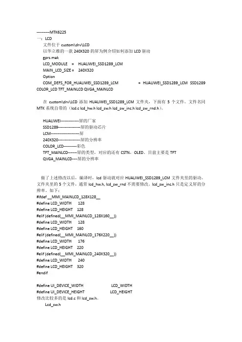
----------MTK6225一:LCD文件位于custom\drv\LCD以华立维的一款240X320的屏为例介绍如何添加LCD驱动gprs.makLCD_MODULE = HUALIWEI_SSD1289_LCMMAIN_LCD_SIZE = 240X320OptionCOM_DEFS_FOR_HUALIWEI_SSD1289_LCM = HUALIWEI_SSD1289_LCM SSD1289 COLOR_LCD TFT_MAINLCD QVGA_MAINLCD在custom\drv\LCD添加HUALIWEI_SSD1289_LCM文件夹,下面有5个文件。
文件名同MTK系统自带的(lcd.c lcd_hw.h lcd_sw.h lcd_sw_inc.h lcd_sw_rnd.h)。
HUALIWEI--------------屏的厂家SSD1289-----------------屏的驱动芯片LCM----------------------屏240X320-----------------屏的分辨率COLOR_LCD----------彩色TFT_MAINLCD-------屏的类型,对应的还有CSTN,OLED。
目前主要是TFTQVGA_MAINLCD----屏的分辨率做了上述修改以后,编译时,lcd驱动就对应HUALIWEI_SSD1289_LCM文件夹里的驱动。
文件夹里的5个文件,通常lcd_hw.h, lcd_sw_rnd不需要修改。
lcd_sw_inc.h只是定义屏的分辨率。
如下:#ifdef __MMI_MAINLCD_128X128__#define LCD_WIDTH 128#define LCD_HEIGHT 128#elif (defined(__MMI_MAINLCD_128X160__))#define LCD_WIDTH 128#define LCD_HEIGHT 160#elif (defined(__MMI_MAINLCD_176X220__))#define LCD_WIDTH 176#define LCD_HEIGHT 220#elif (defined(__MMI_MAINLCD_240X320__))#define LCD_WIDTH 240#define LCD_HEIGHT 320#endif#define UI_DEVICE_WIDTH LCD_WIDTH#define UI_DEVICE_HEIGHT LCD_HEIGHT修改比较多的是lcd.c和lcd_sw.h。
MTK驱动基本介绍MTK(Mediatek Inc.)是台湾联发科技股份有限公司的一个子公司,是一家全球领先的半导体芯片设计公司。
MTK驱动(Mediatek Driver)是联发科技开发的一款设备驱动程序,用于支持和管理MTK系列芯片的硬件设备。
MTK驱动的目的是为了提供对MTK芯片的各种硬件设备的支持,使其能够在计算机系统中正常工作。
MTK芯片广泛用于智能手机、平板电脑、智能家居、物联网等领域的设备,而MTK驱动则起到了连接和协调计算机系统和硬件设备之间的桥梁作用。
1.提供设备识别和连接:MTK驱动可以识别MTK芯片的硬件设备,并与计算机系统进行连接,完成设备的初始化和配置工作。
2.实现设备通信和数据传输:MTK驱动通过与设备之间的通信接口,实现了设备和计算机之间的数据传输和交互,包括文件的读写、音视频的传输和图像的显示等。
3.支持设备管理和控制:MTK驱动可以对MTK芯片的硬件设备进行管理和控制,包括设备的开关、功能设置、驱动安装和升级等。
4.提供系统稳定性和兼容性:MTK驱动经过严格的测试和验证,能够保证在不同的计算机系统环境下的稳定性和兼容性,确保硬件设备能够正常工作。
5.支持开发者和用户的需求:MTK驱动提供了丰富的开发工具和接口,为开发者和用户提供定制化和个性化的驱动支持,方便二次开发和扩展。
2.连接设备和计算机:使用USB数据线或其他连接方式将MTK芯片的硬件设备连接到计算机上。
3.设置设备连接模式:根据设备的不同,选择合适的连接模式,如USB存储模式、USB调试模式等。
4.等待系统安装驱动:当设备连接到计算机后,操作系统会自动检测并安装相应的MTK驱动程序,期间需要等待一段时间。
5.使用设备:一旦驱动安装完成,设备就可以在计算机上正常工作,可以进行文件传输、数据交互、驱动管理等操作。
总之,MTK驱动是一款重要的软件工具,为MTK芯片的硬件设备提供了必要的支持和管理功能,使其能够在计算机系统中正常工作。
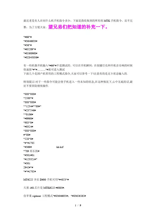
最近老是有人在问什么机手机指令多少,下面是我收集到的所有的MTK手机指令,还不完整,为了方便大家,望兄弟们把知道的补充一下。
*#66*#*#3646633#*#36*#*#65289*#*#8560968#*#82043036#有一些机器开机输入*#66*#不进测试的。
可以在开机瞬间,在按键灯亮和开机音乐响的时候快速按*#*#............*#就可进入测试下面几个是国产机常用的工程模式指令,大家可以参考一下!注意有的是无卡状态输入的.特别提示:对于一些指令可能会使手机进入一些未知的状态,在这种情况下,心中无底的话,最好不要冒险继续操作.*888*888#*2580*#*888*888#**1234#**80#**#237546#**0106#*#9960#*983*0#*#0324#*888*888##*80#*528*0#*#*#1705*#369# hh hsf*789再长按#*#301#01*#123321#**#3012945#*#*#*#1705#MT6225齐乐D600手机可用*#4853*#天基168.芯片是MTK6225 #6803#.仿苹果ciphone工程模式*#83646633#;*#83656565#埃利特仿苹果机*#83646633# *#23642*#联想288/300输入2945#*进入测试模式SIMCOM *#189# *#889#龙旗*#8375#中天ZTA606 无卡开机时不停按*#*#*#…进工程模式仿三星F480 *#65*#仿三星W699工程模式:*#66*# 原厂设定*#8375#看芯片*#3646633#工程模式*#220807#mpr联想I909(MT6228)####72728439#进入工程模式。
仿苹果Siphone芯片MTK6225 I68+小S查看版本:*#8375#工程模式:*#82043036#MT6226####777##.奇怪的是手机没有牌子!仿诺基亚N83手机进入工程模式:*#65289*#仿诺基亚5310XM支持JA V A*#0000# 显示版本号(仿的5310数据)*#06# 查串号*#035670766*001#*#035670766*002# 内存缓存仿诺基亚N95的支持拇指30掌盟平台App游戏仿诺基亚NOKIA8800E-1 按*#0000#查看版本号仿诺基亚N83心机版*#65289*#进入工程模式支持MRP 查看版本待机状态下输入:*#8375#高仿诺基亚N83进入工厂模式代码:*#65289*#仿诺基亚NOKIA E90(中天8898-1)支持java工厂模式输入*#000#台版8800CA带QQ2G内存按*#0000#仿诺基亚8600 *#0000#仿诺基亚8800CE 输入*#3646633#跟*#66*#仿诺基亚8800 用*#10000#进入工程模式仿诺基亚8800e-1用*#10000#进入工程模式原始密码;112235E8D2H------数据#3646633#工程模式35E8E4H------数据#87#AUTOTEST35E8EAH------数据#33778# 序号289BFCH------数据#0044# 设为英文289C44H------数据#0086#设为简体2BA334H------数据#0886#繁体中文设置指令:*#66*#中文语言:*#0086# + send查看版本:*#8375#软件版本:*#8882#测试:*#87#调试:*#8899#默认语言:*#0000#+通话键设置英文:*#0044#+通话键繁体中文:*#0886#+通话键简体中文:*#0086#+通话键串号查询:*#06#原厂设置:*#66*#查看版本:*#8375#工厂指令:*#3646633#自动测试:*#87#软件版本:*#8882#*#035670766*001#*#035670766*002#仿苹果iphone工程模式*#83646633#;*#83656565#A5156指令*#1234# 查看软件版本*#33778# 查看序号查询*#777755999#或*#220807# 查看游戏支持*#0000#+通话键默认语言*#0044#+通话键设置英文*#0886#+通话键繁体中文*#0086#+通话键简体中文*#3646633# 工程模式*#06# 串号查询*#035670766*001# 按拨号键Ctrl Buffer=0 缓冲器(区)*#035670766*002# 按拨号键Task dbg mask=197632 dgb任务掩码我的手机东级星690,双模双待。
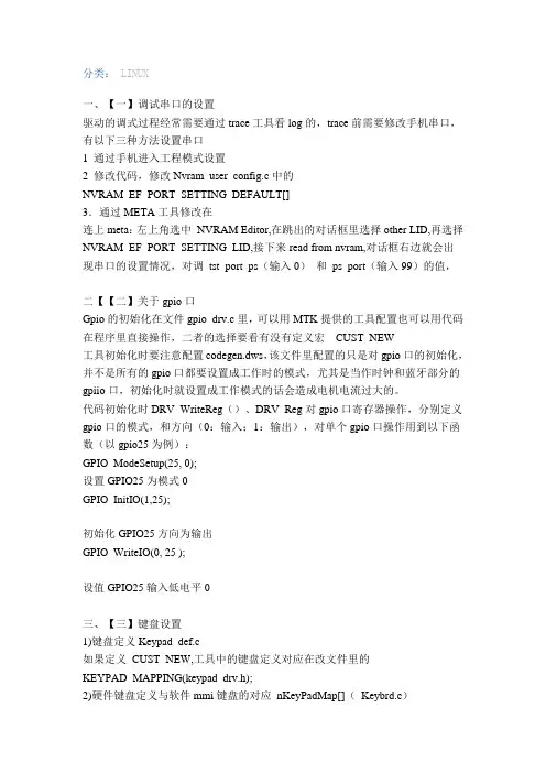
分类:LINUX一、【一】调试串口的设置驱动的调式过程经常需要通过trace工具看log的,trace前需要修改手机串口,有以下三种方法设置串口1 通过手机进入工程模式设置2 修改代码,修改Nvram_user_config.c中的NVRAM_EF_PORT_SETTING_DEFAULT[]3.通过META工具修改在连上meta:左上角选中NVRAM Editor,在跳出的对话框里选择other LID,再选择NVRAM_EF_PORT_SETTING_LID,接下来read from nvram,对话框右边就会出现串口的设置情况,对调tst_port_ps(输入0)和ps_port(输入99)的值,二【【二】关于gpio口Gpio的初始化在文件gpio_drv.c里,可以用MTK提供的工具配置也可以用代码在程序里直接操作,二者的选择要看有没有定义宏__CUST_NEW__工具初始化时要注意配置codegen.dws,该文件里配置的只是对gpio口的初始化,并不是所有的gpio口都要设置成工作时的模式,尤其是当作时钟和蓝牙部分的gpiio口,初始化时就设置成工作模式的话会造成电机电流过大的。
代码初始化时DRV_WriteReg()、DRV_Reg对gpio口寄存器操作,分别定义gpio口的模式,和方向(0:输入;1:输出),对单个gpio口操作用到以下函数(以gpio25为例):GPIO_ModeSetup(25, 0);设置GPIO25为模式0GPIO_InitIO(1,25);初始化GPIO25方向为输出GPIO_WriteIO(0, 25 );设值GPIO25输入低电平0三、【三】键盘设置1)键盘定义Keypad_def.c如果定义CUST_NEW,工具中的键盘定义对应在改文件里的KEYPAD_MAPPING(keypad_drv.h);2)硬件键盘定义与软件mmi键盘的对应nKeyPadMap[](Keybrd.c)3)工程模式键盘测试函数EntryFMKeypadTest()修改键盘测试时界面显示的键的名称1. 做好上面的第一第二两步2. FactoryModeSrc.c开始部分定义添加的键所要显示的名称,值,分别应用到keypad_layout[](确定要显示的位置),keypad_value[]3.在EntryFMKeypadTest()函数中的数组IdleScreenDigits[]里添加要显示的键4)如果要设置一个键不管在什么界面下都起作用的话(如手电筒开关或则其他需求)就需要在键盘的事件响应函数static voidKeyEventHandler(KEYBRD_MESSAGE *eventKey)里设置,根据键值条用相应的响应函数,不过该函数及时在锁屏状态下也会执行的,需要根据需要添加条件语句四、关于LCDlcm背光驱动分为两种控制方式:1. pwm这个是通过调占空比来调节亮度的持续信号;2. PFM这个是通过脉冲的个数来控制LCM背光亮度。

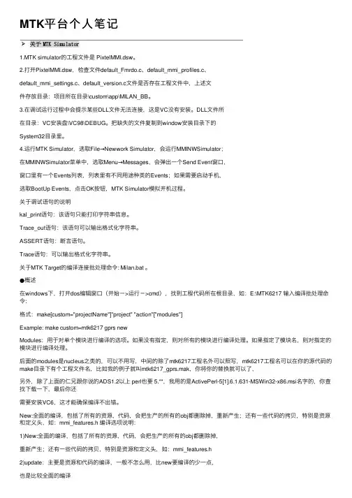
MTK平台个⼈笔记1.MTK simulator的⼯程⽂件是 PixtelMMI.dsw。
2.打开PixtelMMI.dsw,检查⽂件default_Fmrdo.c、default_mmi_profiles.c、default_mmi_settings.c、default_version.c⽂件是否存在⼯程⽂件中,上述⽂件存放⽬录:项⽬所在⽬录\custom\app\MILAN_BB。
3.在调试运⾏过程中会提⽰某些DLL⽂件⽆法连接,这是VC没有安装。
DLL⽂件所在⽬录:VC安装盘\VC98\DEBUG。
把缺失的⽂件复制到window安装⽬录下的System32⽬录⾥。
4.运⾏MTK Simulator,选取File→Newwork Simulator,会运⾏MMINWSimulator;在MMINWSimulator菜单中,选取Menu→Messages,会弹出⼀个Send Event窗⼝,窗⼝⾥有⼀个Events列表,列表⾥有不同⽤途种类的Events;如果需要启动⼿机,选取BootUp Events,点击OK按钮,MTK Simulator模拟开机过程。
关于调试语句的说明kal_print语句:该语句只能打印字符串信息。
Trace_out语句:该语句可以输出格式化字符串。
ASSERT语句:断⾔语句。
Trace语句:可以输出格式化字符串。
关于MTK Target的编译连接批处理命令: Milan.bat 。
●概述在windows下,打开dos编辑窗⼝(开始->运⾏->cmd),找到⼯程代码所在根⽬录,如:E:\MTK6217 输⼊编译批处理命令:格式:make[custom="projectName"]"project" "action"["modules"]Example: make custom=mtk6217 gprs newModules:⽤于对单个模块进⾏编译的选项。

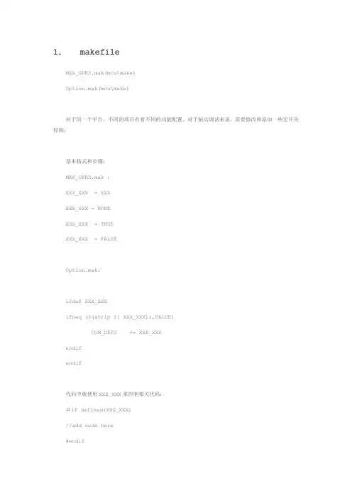
1.makefileMXX_GPRS.mak(mcu\make)Option.mak(mcu\make)对于同一个平台,不同的项目有着不同的功能配置。
对于驱动调试来说,需要修改和添加一些宏开关控制;基本格式和步骤:MXX_GPRS.mak :XXX_XXX = XXXXXX_XXX = NONEXXX_XXX = TRUEXXX_XXX = FALSEOption.mak:ifdef XXX_XXXifneq ($(strip $( XXX_XXX)),FALSE)COM_DEFS += XXX_XXXendifendif代码中就使用XXX_XXX来控制相关代码;#if defined(XXX_XXX)//add code here#endif以MT6226(05c)平台为例:列举一些修改比较频繁的开关:MT6226A MT6226B MT6226M MT6227A MT6227BPLATFORM MT6226MT6226MT6226M MT6227A MT6227B CHIP_VER S00S01S01S00S01LCD_MODULE用于LCM Module控制;详细见No.2CUSTOM_CFLAGS如用JTAG进行DEBUG需打开此开关;注意关闭Watch DogEXT_CAM_MODULE如用外部DSP来控制Sensor;需用到此开关;详见No.3ISP_SUPPORT如Camera没有外挂DSP需打开此开关;CMOS_SENSOR用以区分Sensor的类型;如OV7660;OV9650等NOR_FLASH_TYPE所用NOR Flash的类型;现一般是AMD Series;MSDC_CARD_SUPPORT_TYPE用以是否支持T卡的开关;不支持为NONE;支持为MSDC_SD_MMC BLUETOOTH_SUPPORT用以是否支持蓝牙的开关;不支持为NONE;支持为所用芯片的类型;TOUCH_PANEL_SUPPORT用以是否支持触摸屏的开关;不支持为FALSE;支持为TRUE;MOTION_SENSOR_SUPPORT用以是否支持Motion sensor的开关;不支持为NONE;支持为所用芯片类型MAIN_LCD_SIZE所用LCD的大小;如240X320;176X220;120X160等FM_RADIO_CHIP用以是否支持FM功能;不支持为NONE;支持为所用芯片类型;NAND_SUPPORT用以是否支持NAND FLASH;不支持为FASLE;支持为TRUE PHONE_TYPE滑盖机: SLIDE;翻盖机:CLAMSHELL;平板机:BAR;旋转:SPIN PLATFORM_NAME项目名称;CAMERA_PIXEL所用Sensor象素;默认30万;130万:ONE_MEGA_PIXEL; 200万:TWO_MEGA_PIXEL等等WEBCAM_SUPPORT用以是否支持Web Camera功能开关;支持为TRUE;不支持为FALSE ect…….其他一些开关视项目而定;可以会修改;可能会添加一些开关。
一驱动安装
1,将mtk_usb_驱动_v1.4(驱动文件)与”mtk刷机工具”,复制到你自己指定的目录下。
2,后视镜与电脑USB连接==》关机状态下==》reset ==》电脑桌面右下角会自动弹出驱动(正在安装设备驱动程序软件)
3,电脑桌面“计算机”右键==》管理==》设备管理器==》MTK6575 preloader==>驱动程序==>更新驱动程序==>浏览计算机上的驱动程序文件==>驱动==>SP drivers-v1.4
备注:之前已安装过驱动,就直接第一步,第四步。
二刷机
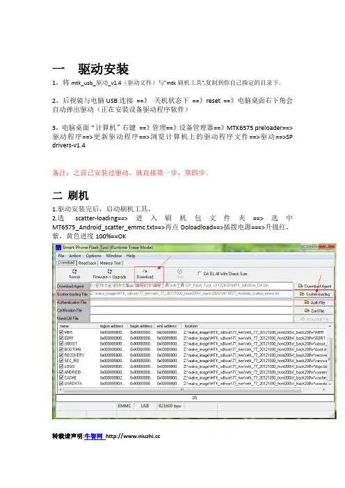
1.驱动安装完后,启动刷机工具,
2.选scatter-loading==>进入刷机包文件夹==>选中MT6575_Android_scatter_emmc.txt==>再点Doloadload==>插拨电源===>升级红,紫,黄色进度100%==OK
转载请声明:牛智网。
1.配置GPIO 并初始化gpio_drv.c内的void GPIO_init(void) 进行初始化1.DRV_WriteReg(GPIO_MODE1,0x0000) 设置模式2.DRV_Reg(GPIO_DIR1) |= 0x00FF 设置方向0 GPIOs are configured as input1 GPIOs are configured as output2.audio_pa配置音频对应Driver部分主要需要留意以下三支档案:afe.c AMP gpo settingaudcoeff.c 首先需要注意是的output channel的配置,配置错误将出现没有声音的现象。
(见audio_驱动.pdf) 此文件需要注意output channel 、FIR setting和echo参数的设置audcoeff_default.h 定义语音增强参数nvram_default_audio.c 此文件主要配置各音阶的音量AUD_VOLUME_CTN :call waiting tone, error tone, warning toneAUD_VOLUME_KEY :keypad tone]AUD_VOLUME_MIC :microphone inputAUD_VOLUME_FMR :FM radio soundAUD_VOLUME_SPH :speech sound (during phone call)AUD_VOLUME_SID :side tone (sound loop-back)AUD_VOLUME_MEDIA :music1.设置模式,方向,上拉gpio_drv.c 里配置2.afe.c 文件里void AFE_SwitchExtAmplifier( char sw_on )设置3.afe2.c 文件里void AFE_TurnOnExtAmplifier( void )void AFE_TurnOffExtAmplifier( void )进行调用.3.触摸屏先初始化,后期是自动配置1.在eint_var.c里看中断2.touch_panel_spi.h 配GPIO 口3.touch_panel_spi.c Implement serial interface4.touch_panel_custom.c Set ADC and coordinate calibration4.FM1.RDA5800_SerialComm.c 配GPIO 口2.RDA5800_drv.c 函数的实现5.跑马灯\背光灯1.custom_equipment.c 或者uem_gpio.c 中找2.SN3726_LIGHT_LED3.lcd_backlight_set6.MT6318 driver1.pmic_custom.c2.Engineer mode3.*#3646633# =>Device=>PMIC7.工程模式参数1.CustResDef.h8.软件调speecher大小1.Audcoeff.c2.DG_DL_SPEECH = 0X1000 指gain = 13.DG_MICPHONE = 0X1400 最大0x2000 gain = 29.项目(6225平台),原先做的900/1800双频,校准综测都是正常的。
MTK平台驱动基本介绍----------MTK6239一:LCD文件位于custom\drv\LCD以菲利浦的一款240 X 400的屏为例介绍如何添加LCD驱动SIMCOM38_08B_GPRS.makLCD_MODULE = SUNRISE_2827TI_LCMMAIN_LCD_SIZE = 240 X 400Option.makCOM_DEFS_FOR_SUNRISE_2827TI_LCM = ILI9326 COLOR_LCD SUNRISE_2827TI_LCMTFT_MAINLCD WQVGA_MAINLCD在custom\drv\LCD添加SUNRISE_2827TI_LCM文件夹,下面有5个文件。
文件名同MTK 系统自带的(lcd.c、lcd_hw.h、lcd_sw.h、lcd_sw_inc.h、lcd_sw_rnd.h)。
SUNRISE -------------- 屏的厂家ILI9326 ----------------- 屏的驱动芯片LCM ---------------------- 屏240 X 400 ----------------- 屏的分辨率COLOR_LCD ---------- 彩色TFT_MAINLCD ------- 屏的类型,对应的还有CSTN,OLED。
目前主要是TFTWQVGA_MAINLCD ---- 屏的分辨率做了上述修改以后,编译时,lcd驱动就对应SUNRISE_2827TI_LCM文件夹里的驱动。
文件夹里的5个文件,通常lcd_hw.h和lcd_sw_rnd不需要修改,lcd_sw_inc.h只是定义屏的分辨率。
如下:#ifdef __MMI_MAINLCD_128X128__#define LCD_WIDTH 128#define LCD_HEIGHT 128#elif (defined(__MMI_MAINLCD_128X160__))#define LCD_WIDTH 128#define LCD_HEIGHT 160#elif (defined(__MMI_MAINLCD_176X220__))#define LCD_WIDTH 176#define LCD_HEIGHT 220#elif (defined(__MMI_MAINLCD_240X400__))#define LCD_WIDTH 240#define LCD_HEIGHT 400#endif#define UI_DEVICE_WIDTH LCD_WIDTH#define UI_DEVICE_HEIGHT LCD_HEIGHT修改比较多的是lcd.c和lcd_sw.h:lcd_sw.h#define LCD_CMD_DMA_MODE --------- 是否使用DMA方式?(DMA简单,速度快,通过MTK的寄存器进行操作,但灵活性差;非DMA方式,直接对地址操作,灵活性好,但速度会有影响。
识别判断MTK手机是什么芯片平台型号的简单方法识别判断MTK手机是什么芯片平台型号的简单方法插上数据线,连接到电脑,当电脑提示找到硬件时,会有芯片型号提示,装好USB驱动后,在同步软件里设置到您的手机对应芯片型号即可同步!如果还看不到下载下面的工具UnknownDeviceIdentifier.这是一个识别机器里未知设备的小工具。
MTK平台手机刷机详细步骤及注意事项网上有很多关于MTK刷机的教程,本人看了一下,教程存在很多的误导,一些教程是针对维修层次写的,根本不适合无维修基础的新手使用,如果照搬应用会造成很不好的后果!这里就刷机的基本详细步骤,根据我的实践经验重新整理一下!希望对大家有帮助!首先说下刷机线,刷机用的刷机线不同于平常用的下载联机线,因为传输的数据不同!下载联机线只能传输读写手机RAM 区的东西,RAM就是用来保存用户数据的存储器,如音乐游戏软件等!用普通的同步软件和数据线就可以随意读写!而刷机要读写的是ROM区的数据,就是手机底层系统的存储器,这个区手机出厂时已经固化烧录在里面,我们要刷的就是这个区的东西!因为手机运行的界面及应用接口等都是在这里面,读写这个区就需要专门的平台和数据线!有时还需要专门的设备!刷机线来源1,可以用诺基亚DK-5的下载线自己改制,2,内含PL2303芯片的数据线。
只要是PL2303驱动的数据线都可以PL2303数据线自制MTK系列刷机线图解教程MTK, 数据线, 教程, 图解现在MTK芯片手机已经占据了手机市场的半壁江山,同时MTK 的软件问题也很多。
如果各位想自己简单的刷机解锁的话。
可以参考下面的教程自制刷机数据线:一线通,PL2303刷机线,新手自制刷机线刷机教程。
刷机线来源1,推荐用诺基亚DK-5的下载数据线,2,内含PL2303芯片的数据线。
只要是PL2303驱动的数据线都可以的。
改线篇,如果我们自己手上有这个线,没有改装过,可以自己来改一根,只要接四根线出来就可以了。
MTK的驱动和MMI经验总结1.Windows必须安装在C盘,否则会出现modis编译问题。
2.语言和输入法移植2.1资源修改–这是我们需要修改的,2.2开始MTK已经帮你做好了。
2.1.1在mcu\plutommi\Customer\CustResource\PLUTO_MMI\ref_list.txt中添加新语言的字符串资源。
2.1.2用MCT工具生成新的字库,需要注意的是Language ID必须和ref_list.txt中一致。
2.1.3输入法资源包括Zi、T9和CStar。
2.1.3.1Zia.新建mcu\vendor\inputmethod\ZI\project\PROJECTNAME\v?_official\目录。
b.将第三方提供的Zi文件拷贝到该目录。
c.将所有ZI8DatXX.c文件扩展名改成.h文件,并将其包含到IMEResZi.h中。
d.将输入资源添加到mtk_gIMELDBArray 数组中。
e.上面步骤,第三方可能已经提供IMEResZi.h文件。
如果提供了就不用这些步骤了。
2.1.3.2T9将代码放到下面目录:mcu\vendor\inputmethod\T9\project\PROJECTNAME\v?_official\移植比较麻烦,具体参考:SOP_T9_Input_Method_Resource_Generation_07A.pdfSOP_T9_Input_Method_Resource_Generation_08B.pdfSOP_T9_Input_Method_Resource_Generation_09BV2.pdf2.1.3.3CStar不说了2.2SSC有几个文件需要修改。
a.mcu\ \plutommi\mmi\SSC\SSCInc\SSCStringHandle.h:增加新的SSC码,需要和ref_list.txt、FontRes.c中的一致。
#define SSC_AUTO "*#0000#"#define SSC_SCHINESE "*#0086#"#define SSC_TCHINESE "*#0886#"#define SSC_ENGLISH "*#0044#"#define SSC_DEFAULT "*#0044#"#define SSC_SPANISH "*#0034#"//添加你的SSC码//#define SSC_XXXXX "*#00XX#"2.3mcu\ \plutommi\mmi\SSC\SSCInc\SSCStringHandle.c:将新的SSC码加入到ssc_table2表中。
Revision: 0.1 Preliminary Information Document Number:Driver Customization GuideBaseband Device DriverMediaTekLegal DisclaimerBY OPENING OR USING THIS FILE, BUYER HEREBY UNEQUIVOCALLY ACKNOWLEDGES AND AGREES THAT THE SOFTWARE/FIRMWARE AND ITS DOCUMENTATIONS (“MEDIATEK SOFTWARE”) RECEIVED FROM MEDIATEK AND/OR ITS REPRESENTATIVES ARE PROVIDED TO BUYER ON AN “AS-IS” BASIS ONLY. MEDIATEK EXPRESSLY DISCLAIMS ANY AND ALL WARRANTIES, EXPRESS OR IMPLIED, INCLUDING BUT NOT LIMITED TO THE IMPLIED WARRANTIES OF MERCHANTABILITY, FITNESS FOR A PARTICULAR PURPOSE OR NONINFRINGEMENT. NEITHER DOES MEDIATEK PROVIDE ANY WARRANTY WHATSOEVER WITH RESPECT TO THE SOFTWARE OF ANY THIRD PARTY WHICH MAY BE USED BY, INCORPORATED IN, OR SUPPLIED WITH THE MEDIATEK SOFTWARE, AND BUYER AGREES TO LOOK ONLY TO SUCH THIRD PARTY FOR ANY WARRANTY CLAIM RELATING THERETO. MEDIATEK SHALL ALSO NOT BE RESPONSIBLE FOR ANY MEDIATEK SOFTWARE RELEASES MADE TO BUYER’S SPECIFICATION OR TO CONFORM TO A PARTICULAR STANDARD OR OPEN FORUM.BUYER'S SOLE AND EXCLUSIVE REMEDY AND MEDIATEK'S ENTIRE AND CUMULATIVE LIABILITY WITH RESPECT TO THE MEDIATEK SOFTWARE RELEASED HEREUNDER WILL BE, AT MEDIATEK'S OPTION, TO REVISE OR REPLACE THE MEDIATEK SOFTWARE AT ISSUE, OR REFUND ANY SOFTWARE LICENSE FEES OR SERVICE CHARGE PAID BY BUYER TO MEDIATEK FOR SUCH MEDIATEK SOFTWARE AT ISSUE.THE TRANSACTION CONTEMPLATED HEREUNDER SHALL BE CONSTRUED IN ACCORDANCE WITH THE LAWS OF THE STATE OF CALIFORNIA, USA, EXCLUDING ITS CONFLICT OF LAWS PRINCIPLES.Revision HistoryRevision DateAuthor Comments(mm/dd/yyyy)0.1 11/03/2003 Arthur Shieh Draft version, revised from MTK Device Driver design documentTable of ContentsLegal Disclaimer (2)Revision History (3)Table of Contents (4)1Introduction (7)1.1Overview (7)1.2References (7)2ADC Customization (8)2.1Overview (8)2.2Library Module (8)2.3Const Variables (8)2.3.1ADC channel definitions (8)2.4Data Structure (9)2.4.1adc_channel_type (9)2.5Functions (9)2.5.1custom_adc_get_channel (9)3Accessory (AUX) Task (10)3.1Overview (10)3.2Library Module (10)3.3Data Structures (10)3.3.1AUX_ID (10)3.4Message (11)3.4.1MSG_ID_AUX_PLUGIN (11)3.4.2MSG_ID_AUX_PLUGOUT (11)3.4.3MSG_ID_AUX_ID (11)4Charge parameters (12)4.1Overview (12)4.2Library Module (12)4.3Const Variables (12)4.3.1GPIO configure for charge control/vibrator (12)4.3.2Battery/charge Parameters (12)4.3.3Charge state parameters (13)4.3.4Measured parameters (15)5EINT parameters (17)5.1Overview (17)5.2Library Module (17)5.3Definition (17)6Keypad parameters (18)6.1Overview (18)6.2Library Module (18)7UART parameters (20)7.1Overview (20)7.2Library Module (20)7.3Definition (20)8Customize driver initialize (21)8.1Overview (21)8.2Library Module (21)8.3Example (21)9Custom Equipment Configuration (22)9.1Overview (22)9.2Library Module (22)9.3Data Structure (22)9.3.1GPIO_MAP_ENTRY (22)9.3.2GPIO_LABELID_ENUM (22)9.3.3Const Value (23)9.4Function (24)9.4.1custom_cfg_hw_aud_output_path (24)9.4.2custom_cfg_hw_aud_input_path (25)9.4.3custom_cfg_outward_gpio_port (26)9.4.4custom_cfg_gpio_set_level (27)10Device Driver Level Information Configuration (30)10.1Overview (30)10.2References (30)10.3Library Module (30)10.4Data Structure and Functions (30)10.4.1Overview (30)10.4.2Constant Variable (30)10.4.3Data Structure (31)10.4.4Global Variables (32)10.4.5Functions (33)10.5LCD Level Information (34)10.5.1Overview (34)10.5.2Functions (34)10.6PWM Level Information (34)10.6.1Overview (34)10.6.2Functions (34)10.7Battery Level Information (35)10.7.1Overview (35)10.7.2Functions (35)11LED/LCD/Vibrator Pattern Configuration (36)11.1Overview (36)11.2Library Module (36)11.3Data Structure (36)11.3.1PATTERN_ID (36)11.3.2PATTERN_TYPE (37)11.3.3LED_PATTERN_STRUCT (37)11.3.4LCD_PATTERN_STRUCT (37)11.3.5VIB_PATTERN_STRUCT (37)11.3.6Const Value (38)11.4Pattern Customization Procedure (38)11.4.1Overview (38)11.4.2 A Step-by-Step Example (38)12NVRAM Configuration (42)12.1Overview (42)12.2Library Module (43)12.3Configuration Guide (44)12.3.1Define LID (44)12.3.2Define Size and Total (44)12.3.3Define Default Value (45)12.3.4Define Data Item (46)12.4Modify Data Version (47)12.4.1Final step (47)12.5Constraints (47)12.5.1Constraints (47)12.5.2Fields in Primitives (48)12.6Fields in Primitives (48)12.7Default Value (48)12.8Read-Only attribute (48)Index of Figures (49)1 Introduction1.1 OverviewThis document describes the functional interface of the customized drivers. Basically, these files are allocated at custom\drv\misc_drv\{platform} folder. Some parameters are required to be modified in various customized setting. The customized parameters are ,as a result, placed in the custom folder.Note that: for LCD driver detailed information, please refer to “Customer Device Driver Document - LCD driver”.1.2 ReferencesMT6205B GSM Baseband Processor Data SheetExce Lee, “Non-Volatile Memory Data Service Functional Specification”, August 2002.WS Lin, “NVRAM Task Driver Interface”, October 20022 ADC Customization2.1 OverviewDefine the physical ADC channel mapping. For instance, “const kal_uint8 ADC_VBAT = 0” means using ADC channel 0 for battery measurement. It will be modified according to the physical layout. The number of ADC channels depends on the baseband controller.Module2.2 Librarycustom\drv\misc_drv\{platform}adc_channel.hadc_channel.cVariables2.3 Const2.3.1 ADC channel definitionsDefinition:ADC_VBAT,ADC_VBATTMP,ADC_ACCESSORYID,ADC_VISENSE,ADC_VCHARGERParameters:Parameter DescriptionADC_VBAT Battery voltage channelADC_VBATTMP Battery temperature voltage channelADC_ACCESSORYID Accessory voltage channelADC_VISENSE Charge current sense voltage channelADC_VCHARGER Charger voltage channelExample:const kal_uint8 ADC_VBAT = 0;/* Battery voltage channel is at channel 0 */const kal_uint8 ADC_VBATTMP = 1;/* Battery temperature voltage channel is at channel 1 */const kal_uint8 ADC_ACCESSORYID = 2;/* Accessory voltage channel is at channel 2 */const kal_uint8 ADC_VISENSE = 3;/* Charge current sense voltage channel is at channel 3 */const kal_uint8 ADC_VCHARGER = 4;/* Charger voltage channel is at channel 4 */2.4 DataStructure2.4.1 adc_channel_typeDefinition:typedef enum {vbat_adc_channel,visense_adc_channel,vbattmp_adc_channel,vcharger_adc_channel,aux_adc_channel} adc_channel_type;Note that: this data structure is only used in Engineering Mode.Members:Members Descriptionvbat_adc_channel Battery voltage channel typevbattmp_adc_channel Battery temperature voltage channel typeaux_adc_channel Accessory voltage channel typevisense_adc_channel Charge current sense voltage channel typevcharger_adc_channel Charger voltage channel type2.5 Functions2.5.1 custom_adc_get_channelkal_uint8 custom_adc_get_channel(adc_channel_type type)This function is to obtain the ADC channel information. This function is only used in Engineering Mode. Parameters:Parameter DescriptionType =vbat_adc_channel, vbattmp_adc_channel, aux_adc_channel,visense_adc_channel, vcharger_adc_channelReturn value:ADC channel numberExample:None3 Accessory (AUX) Task3.1 OverviewThis task is used to detect the accessory device (UART, EARPHONE, send/end key… etc) which is depended on base band board layout.Module3.2 Librarycustom\drv\misc_drv\{platform}auxmain.cinterface\hwdrvdrvsignals.h3.3 DataStructures3.3.1 AUX_IDDefinition:typedef enum{AUX_ID_PLUGOUT=0,AUX_ID_EARPHONE,AUX_ID_KEY_PRESS,AUX_ID_KEY_RELEASE,AUX_ID_UART,AUX_ID_CLAM_OPEN,AUX_ID_CLAM_CLOSE,AUX_MAX_ID}AUX_ID;This enum defines all of the accessory ids. If phone add another accessory device, this enum definition should be modified.Members:Members DescriptionAUX_ID_PLUGOUT Accessory device is plugged outAUX_ID_EARPHONE Accessory device is plug in, and accessory device is earphone.AUX_ID_KEY_PRESS KEY PRESS event.AUX_ID_KEY_RELEASE KEY RELEASE event.AUX_ID_UART Accessory device is plug in, and accessory device is UART.AUX_ID_CLAM_OPEN Open the phonephonetheAUX_ID_CLAM_CLOSE ClipAUX_MAX_ID Maximum number of accessory device.3.4 Message3.4.1 MSG_ID_AUX_PLUGINDescription:This primitive is used to notify AUX that the device is plugged in. (HISR->AUX task)Local Parameter:N/AReference:N/A3.4.2 MSG_ID_AUX_PLUGOUTDescription:This primitive is used to notify AUX that the device is plugged out. (HISR->AUX task)Local Parameter:N/AReference:N/A3.4.3 MSG_ID_AUX_IDDescription:This primitive is used to notify UEM what the accessory id is issued. (AUX task->UEM)Local Parameter:Name Type Description Ref.Aux_id_struct struct AUX id See BelowReference:typedef struct {LOCAL_PARA_HDRAUX_ID aux_id;} aux_id_struct;4 Charge parameters4.1 OverviewThese parameters states boundary conditions and exception conditions for charging algorithm, such as the conditions, when the charge action should be stopped, when battery voltage is high, or when battery temperature is high, or when charge current is high and etc.There are many const variables to describe these parameters, and these variables are made available for other modules by declaring “extern ” in batvalue.h.Module4.2 Librarycustom\drv\misc_drv\{platform}batvalue.hchr_parameter.cVariables4.3 Const4.3.1 GPIO configure for charge control/vibratorDefinition:GPIO_CHRCTRL,GPIO_VIBRATOR,Parameters:Parameter Descriptionto control charge or notchannelGPIO_CHRCTRL GPIOGPIO_VIBRATOR GPIO channel to control vibratorExample:/*use GPIO12 to control charge or not*/const kal_uint8 GPIO_CHRCTRL = 12;/*use GPIO15 to control vibrator*/const kal_uint8 GPIO_VIBRATOR = 15;Parameters4.3.2 Battery/chargeDefinition:Typical_LI_BATTYPE,Typical_NI_BATTYPE,ICHARGE_TBD,BATTMP_0C,BATTMP_45C,MAX_VBAT_LI,MAX_VBAT_NI,CVPROTECT_HIGH,CVPROTECT_LOWParameters:Parameter DescriptionTypical_LI_BATTYPE Battery id voltage to check LI battery or NI battery. If phone doesn’t support Li andNI-MH battery together, this value may be useless. unit: uV. For example, “thevalue = 4000000” means “voltage = 4V”.Typical_NI_BATTYPE Battery id voltage to check LI battery or NI battery. If phone doesn’t support Li andNI-MH battery together, this value may be useless. unit: uV.ICHARGE_TBD If measured charge current achieves this value, “over charge current” event isissued. unit: uA.BATTMP_0C The voltage value when battery temperature is 0℃. unit: uV.BATTMP_45C The voltage value when battery temperature is 45℃. unit: uV.MAX_VBAT_LI If measured battery(LI) voltage in charge mode archives this value, “over voltageprotect ” event is issued. unit: uV.MAX_VBAT_NI If measured battery(NIMH) voltage in charge mode achieves this value, “overvoltage protect ” event is issued. unit: uV.CVPROTECT_HIGH If measured battery(LI) voltage in charge mode achieves this value, and phone is intalk mode, the charge action will automatically stop to protect the battery. unit: uV. CVPROTECT_LOW If measured battery(LI) voltage in charge mode achieves this value, and phone is intalk mode, the charge action will automatically start again. unit: uV.Example:Noneparametersstate4.3.3 ChargeDefinition:CHVBATOFF,CHARGE1_LI,ICHARGE2_LI,CHVBATOFF2_LI,CHVBATTEMP_NI,CHVBATOFF2_NI,ICHARGE_HIGHLEVEL,ICHARGE_LOWLEVEL,PRE_TON,PRE_TOFF,TOPOFF_TON,TOPOFF_TOFF,BATFULL_TON_LI,BATFULL_TOFF_LI,BATFULL_TON_NI,BATFULL_TOFF_NI,BATFULL_TOFF,BATHOLD_OFF,Parameters:Parameter DescriptionCHVBATOFF The battery voltage achieves this value when charge off, the charging algorithmwill enter charge Fast Mode.CHARGE1_LI When battery is Li-Ion and the charge current is less than this value, thecharging algorithm will enter charge TOPOFF mode.ICHARGE2_LI When battery is Li-Ion and the charge current is less than this value, thecharging algorithm will enter charge complete mode.CHVBATOFF2_LI When battery is Li-Ion at charge complete mode, and the battery voltage is lessthan this value, the charging algorithm will enter charge Fast mode. CHVBATTEMP_NI When battery is NiMH and the measured battery temperature is larger than thistemperature, the battery will enter charge complete mode.CHVBATOFF2_NI When battery is NiMH at the charge complete mode, and the battery voltage isless than this value, the charging algorithm will enter charge Fast mode. ICHARGE_HIGHLEVEL When battery is at charge Fast mode, this parameter andICHARGE_LOWLEVEL are used to expect the charge period. The period isdepended on TONOFFTABLE.ICHARGE_LOWLEVEL When battery is at charge Fast mode, this parameter andICHARGE_HIGHLEVEL are used to expect the charge period. The period isdepended on TONOFFTABLE.PRE_TON Charge on period in Pre charge mode.PRE_TOFF Charge off period in Pre charge mode.TOPOFF_TON Charge on period in TOPOFF charge mode.TOPOFF_TOFF Charge off period in TOPOFF charge mode.BATFULL_TON_NI Charge on period in BATFULL charge mode & charge is enabled. (NiMH) BATFULL_TOFF_NI Charge off period in BATFULL charge mode & charge is enabled. (NiMH) BATFULL_TOFF Charge off period in BATFULL charge mode & charge is disable. (Li&MiMH) BATHOLD_OFF Charge off period in charge hold mode.Example:const kal_int32 Typical_LI_BATTYPE = 1100000;const kal_int32 Typical_NI_BATTYPE = 1100000;const kal_int32 ICHARGE_TBD = 3000000;const kal_int32 BATTMP_0C = -100000000;const kal_int32 BATTMP_45C = 100000000;const kal_int32 MAX_VBAT_LI = 4500000;const kal_int32 MAX_VBAT_NI = 5500000;const kal_int32 ICHARGE1_LI = 250000; /*250ma,FAST->TOPOFF*/const kal_int32 ICHARGE2_LI = 60000; /*60ma,TOPOFF->BATFULL*/const kal_int32 CHVBATOFF2_LI = 4100000; /*BATFULL->FAST*/const kal_int32 CHVBATTEMP_NI = 100000000; /*50oC,FAST->BATFULL*/const kal_int32 CHVBATOFF2_NI = 4100000;const kal_int32 ICHARGE_HIGHLEVEL = 600000; /*600ma,for table search*/const kal_int32 ICHARGE_LOWLEVEL = 400000; /*400ma,for table search*/const kal_int32 CHVBATOFF = 3400000;const kal_int32 ICHARGE1_LI = 250000; /*250ma,FAST->TOPOFF*/const kal_int32 ICHARGE2_LI = 60000; /*60ma,TOPOFF->BATFULL*/const kal_int32 CHVBATOFF2_LI = 4100000; /*BATFULL->FAST*/const kal_int32 CHVBATTEMP_NI = 100000000; /*50oC,FAST->BATFULL*/const kal_int32 CHVBATOFF2_NI = 4100000;const kal_int32 ICHARGE_HIGHLEVEL = 600000; /*600ma,for table search*/const kal_int32 ICHARGE_LOWLEVEL = 400000; /*400ma,for table search*/const kal_int32 CVPROTECT_HIGH = 4050000;const kal_int32 CVPROTECT_LOW = 3800000;/*Time delay*//* PRE CHARGE ,search table*//*TON = 3s,TOFF=2s*/const kal_uint32 PRE_TON = 3;const kal_uint32 PRE_TOFF = 2;/* FAST CHARGE ,search table*//*TON = 3s,TOFF=0s*/const kal_uint32 TOPOFF_TON = 3;const kal_uint32 TOPOFF_TOFF = 0;const kal_uint32 BATFULL_TON_NI = 1; /*unit : second*/const kal_uint32 BATFULL_TOFF_NI = 9;const kal_uint32 BATFULL_TOFF = 6;const kal_uint32 BATHOLD_OFF = 10;parameters4.3.4 MeasuredOverview:These parameters are used to translate the ADC values got from auxiliary ADC units into real voltages values and to calculate the charging current. The ADC is calibrated based on a linear relation assumption between ADC readings and the real voltage level.Definition:adc_cali_param,adc_volt_factor,CurrOffset,ADC_ISENSE_RESISTANCE_FACTORParameters:Parameter DescriptionADC calibration parameters specify thestructure,adc_cali_param ADC_CALIDATAadc_slop & adc_offset parameters.adc_volt_factor The ADC calibration is dependent on the voltage of battery. Therefore, themeasured voltage should be multiplied with this factor.CurrOffset The measured charge current is “Battery current” + “ baseband (BB)current”. This parameter specifies the BB current.ADC_ISENSE_RESISTANCE_FACTOR When evaluate the current, the resistance must divide the difference of twovoltages. The parameter is equal to “1/R”.Note that: The measure voltage will be: V= (adc_slop*adc_value+adc_offset) * adc_volt_factor.The measured current will be (V1-V2)/R = (V1-V2)* ADC_ISENSE_RESISTANCE_FACTORThe actual battery charge current will be (V1-V2)* ADC_ISENSE_RESISTANCE_FACTOR – CurrOffsetExample:const kal_uint16 ADC_ISENSE_RESISTANCE_FACTOR = 3; /*1/0.3333*/ADC_CALIDATA adc_cali_param ={{5369,5369,5369,5369,5369},{(60428),(60428),(60428),(60428),(60428)}};const kal_uint16 adc_volt_factor[ADC_MAX_CHANNEL] = {100, /* = 100% */50, /* = 50% */50, /* = 50% */100, /* = 100% */250 /* = 250% */};const kal_int32 CurrOffset[3] = /*Only support 3 state, if don’t support any state, just specify the same value*/ {100000, //100ma100000,100000};5 EINT parameters5.1 OverviewThese parameters define the assignment for each external interrupt.Module5.2 Librarycustom\drv\misc_drv\{platform}eint_def.c5.3 DefinitionAUX_EINT_NOCHRDET_EINT_NOMELODY_EINT_NOParameters:Parameter DescriptionAUX_EINT_NO The external interrupt channel number for accessory id check CHRDET_EINT_NO The external interrupt channel number for charger detection. MELODY_EINT_NO The external interrupt channel number for melody Example:const kal_uint8 AUX_EINT_NO = 0; /*EINT Channel 0 is for accessory id check */ const kal_uint8 CHRDET_EINT_NO = 1; /*EINT Channel 1 is for charger detection */const kal_uint8 MELODY_EINT_NO = 2; /*EINT Channel 2 is for melody */6 Keypad parameters6.1 OverviewThese parameters define the assignment of the physical keypad scan table. The keypad array varies according the physical layout.6.2 Library Modulecustom\drv\misc_drv\{platform}keypad_def.cExample :#define DEVICE_KEY_0 0#define DEVICE_KEY_1 1#define DEVICE_KEY_2 2#define DEVICE_KEY_3 3#define DEVICE_KEY_4 4#define DEVICE_KEY_5 5#define DEVICE_KEY_6 6#define DEVICE_KEY_7 7#define DEVICE_KEY_8 8#define DEVICE_KEY_9 9#define DEVICE_KEY_STAR 10#define DEVICE_KEY_HASH 11#define DEVICE_KEY_VOL_UP 12#define DEVICE_KEY_VOL_DOWN 13#define DEVICE_KEY_UP 14#define DEVICE_KEY_DOWN 15#define DEVICE_KEY_LEFT 16#define DEVICE_KEY_RIGHT 17#define DEVICE_KEY_MENU 18#define DEVICE_KEY_FUNCTION 19#define DEVICE_KEY_SK_LEFT 20#define DEVICE_KEY_SK_RIGHT 21#define DEVICE_KEY_SEND 22#define DEVICE_KEY_END 23#define DEVICE_KEY_POWER 24#define DEVICE_KEY_CLEAR 25#define MAX_DEVICE_KEYS 26const kal_uint8 keypad[32] ={/* row 0 */DEVICE_KEY_SK_LEFT, //0x43,/*pw*/DEVICE_KEY_SK_RIGHT, //0x5e,/*send*/ DEVICE_KEY_SEND, //0x61,/*clear*/ DEVICE_KEY_END, //0x56,/*end*/ DEVICE_KEY_MENU, //0x45,/* *//* row 1 */DEVICE_KEY_UP, //0x2d,/*up*/DEVICE_KEY_1, //0x31,/*1*/DEVICE_KEY_2, //0x32,/*2*/DEVICE_KEY_3, //0x33,/*3*/DEVICE_KEY_LEFT, /* *//* row 2 */DEVICE_KEY_DOWN, //0x62,/*down*/ DEVICE_KEY_4, //0x34,/*4*/DEVICE_KEY_5, //0x35,/*5*/DEVICE_KEY_6, //0x36,/*6*/DEVICE_KEY_RIGHT, /* *//* row 3 */DEVICE_KEY_VOL_UP, //0xFE,/*shift*/ DEVICE_KEY_7,//0x37, /*7*/DEVICE_KEY_8,//0x38, /*8*/DEVICE_KEY_9,//0x39, /*9*/DEVICE_KEY_FUNCTION, /* *//* row 4 */DEVICE_KEY_VOL_DOWN,//0xFE,/* */DEVICE_KEY_STAR, //0x2a,/***/DEVICE_KEY_0, //0x30,/*0*/DEVICE_KEY_HASH, //0x23,/*#*/DEVICE_KEY_CLEAR, /* *//* row 5 */0xFE,0xFE,0xFE,0xFE,0xFE,0xFE,0xFE};7 UART parameters7.1 OverviewThese parameters are used for defining the size of the UART ring buffers. For each UART port, there are three ring buffers, which are Rx ring buffer, Tx ring buffer and Tx ISR ring buffer. Tx ISR ring buffer is special for ISR usage to avoid race condition issues. If the UART is always busy for data transfer, you may increase the buffer length to prevent data overrun situation.Module7.2 Librarycustom\drv\misc_drv\{platform}uart_def.c7.3 DefinitionUART_RxRingBufferLength,UART_TxRingBufferLength,UART_TxRingBufferLength_ISRParameters:Parameter DescriptionUART_RxRingBufferLength Rx ringbuffer lengthUART_TxRingBufferLength Tx ringbuffer lengthUART_TxRingBufferLength_ISR Tx isr ringbuffer lengthExample:const kal_uint16 UART_RxRingBufferLength[MAX_UART_PORT_NUM] = {2048, /*UART1*/2048, /*UART2*/};const kal_uint16 UART_TxRingBufferLength[MAX_UART_PORT_NUM] = {2048, /*UART1*/2048, /*UART2*/};const kal_uint16 UART_TxRingBufferLength_ISR[MAX_UART_PORT_NUM] = {3072, /*UART1*/3072, /*UART2*/};8 Customize driver initialize8.1 OverviewA custom_drv_init function will be called at the end of the Drv_Init function, which is a function called during boot-up to initialize the peripheral devices in the system. This custom_drv_init specifies the initialization of customized drivers, e.g. GPIO, PWM, Alerter, and LCD. Basically, the initialization function is required to be modified by platform setting.Meanwhile in custom_drv_init.c, the EMI Node is also initialized here to configure the external flash and external SRAM.8.2 LibraryModulecustom\drv\misc_drv\{platform}custom_drv_init.c8.3 Exampleconst EMI_NODE_TYPE EMI_Node[EMI_NUMBER_OF_ENTRIES] ={/* Flash */{EMI_CS0, EMI_NORMAL_MODE, EMI_2_WAIT_STATE, EMI_1_WAIT_STATE, EMI_NO_PAGE, EMI_0_WAIT_STATE, EMI_16BIT_DEVICE},/* SRAM */{EMI_CS1, EMI_NORMAL_MODE, EMI_2_WAIT_STATE, EMI_1_WAIT_STATE, EMI_NO_PAGE, EMI_0_WAIT_STATE, EMI_16BIT_DEVICE}};void custom_drv_init(void){GPIO_init(); /* configure GPIO for debugging */spi_ini(); /* For LCD module */LCD_FunConfig();Alter_init();#ifndef __L1_STANDALONE__PWM_initialize();#endif}9 Custom Equipment Configuration9.1 OverviewThis part describes how to configure the GPIO/PWM/Audio inward/outward path for application according to hardware layout.9.2 LibraryModulecustom\drv\misc_drv\{platform}custom_equipment.hcustom_equipment.c9.3 DataStructure9.3.1 GPIO_MAP_ENTRYDefinition:typedef struct _GPIO_MAP_ENTRY {unsigned char vaild;unsigned char port;const unsigned char *netname;const unsigned char *netname2;} GPIO_MAP_ENTRY;Members:Members Descriptionvaild GPIO valid flagportport Physicalnetname Net name 1netname2 Net name 29.3.2 GPIO_LABELID_ENUMDescription:GPIO labeled ID, logical tag for each GPIO functionDefination:typedef enum {GPIO_LABEL_REN = 0x0,GPIO_LABEL_OPOFFB,GPIO_LABEL_SUBBLEN,GPIO_LABEL_LCDBL,GPIO_LABEL_CHRCNTL,GPIO_LABEL_GEN,GPIO_LABEL_BEN,GPIO_LABEL_VIBEN,GPIO_LABELID_8,GPIO_LABELID_9,GPIO_LABELID_11,GPIO_LABELID_10,GPIO_LABELID_12,GPIO_LABELID_13,GPIO_LABELID_14,GPIO_LABELID_15,GPIO_LABELID_16,GPIO_LABELID_17,GPIO_LABELID_18,GPIO_LABELID_19,GPIO_LABELID_20,GPO_LABELID_0,GPO_LABELID_1,GPO_LABELID_2,/* should NOT modify this value*/GPIO_LABELID_MAX} GPIO_LABELID_ENUM;Value9.3.3 ConstName Value DescriptionGPIO_OFF 0x0 GPIO turn offGPIO_ON 0x1 GPIO turn onvalidGPIOGPIO_INVAILD 0x0invalid GPIO_VAILD 0x1GPIOdefined speaker device 1 identifier AUDIO_DEVICE_SPEAKER 0 Applicationdefined microphone device identifier AUDIO_DEVICE_MICROPHONE 1 ApplicationAUDIO_DEVICE_BUZZER 2 ReservedAUDIO_DEVICE_GMI 3 Reserveddefined speaker device 2 identifier AUDIO_DEVICE_SPEAKER2 4 Applicationdefined loudspeaker device identifier AUDIO_DEVICE_LOUDSPEAKER 5 ApplicationAUDIO_DEVICE_SPEAKER_BOTH 6 Application defined identifier for both speaker device 1and 2defined input device 1 identifier AUDIO_DEVICE_MIC1 0 Applicationdefined input device 2 identifier AUDIO_DEVICE_MIC2 1 ApplicationL1 audio speaker 1 output pathL1SP_SPEAKER1 HardwaredependL1 audio speaker 2 output pathL1SP_SPEAKER2 HardwaredependL1SP_LOUD_SPEAKER Hardware L1 audio loudspeaker output pathdependGPIO_DEV_LED_MAINLCD 0 Application defined Main LCD backlight device identifierdefined Sub LCD backlight device identifier GPIO_DEV_LED_SUBLCD 1 Applicationdefined Status LED R identifier GPIO_DEV_LED_STATUS_1 2 Applicationdefined Status LED G identifier GPIO_DEV_LED_STATUS_2 3 Applicationdefined Status LED B identifier GPIO_DEV_LED_STATUS_3 4 Applicationdefined Keypad backlight identifier GPIO_DEV_LED_KEY 5 ApplicationGPIO_DEV_VIBRATOR 6 Application defined Vibrator identifierGPIO_DEV_FLASHLIGHT 7 Application defined FlashLight identifierGPIO_DEV_RESERVED1 ~ 12 8 ~ 19 Reserved9.4 Function9.4.1 custom_cfg_hw_aud_output_pathkal_uint8 custom_cfg_hw_aud_output_path( kal_uint8 speaker_id );Get L1 audio output path for application use.Parameters:Members Value DescriptionApplication defined speaker device, speaker_id AUDIO_DEVICE_SPEAKERAUDIO_DEVICE_BUZZERAUDIO_DEVICE_GMIAUDIO_DEVICE_SPEAKER2AUDIO_DEVICE_LOUDSPEAKERAUDIO_DEVICE_SPEAKER_BOTHReturn value:L1SP_SPEAKER1L1SP_SPEAKER2L1SP_LOUD_SPEAKERExample:kal_uint8 custom_cfg_hw_aud_output_path( kal_uint8 speaker_id ){kal_uint8 audio_device_out = L1SP_SPEAKER1;switch(speaker_id){case AUDIO_DEVICE_SPEAKER/*AUDIO_OUT_SPEAKER1*/:audio_device_out = L1SP_SPEAKER1;break;case AUDIO_DEVICE_SPEAKER2/*AUDIO_OUT_SPEAKER2*/:audio_device_out = L1SP_SPEAKER2;break;case AUDIO_DEVICE_LOUDSPEAKER/*AUDIO_OUT_LOUDSPEAKER*/:audio_device_out = L1SP_LOUD_SPEAKER;break;case AUDIO_DEVICE_SPEAKER_BOTH: /* AUDIO_OUT_SPEAKER1 and AUDIO_OUT_SPEAKER2 */ audio_device_out = (L1SP_LOUD_SPEAKER| L1SP_SPEAKER2);break;case AUDIO_DEVICE_BUZZER/*AUDIO_OUT_BUZZER*/:case AUDIO_DEVICE_GMI/*AUDIO_OUT_GMI*/:audio_device_out = L1SP_LOUD_SPEAKER;break;default:break;}return audio_device_out;}9.4.2 custom_cfg_hw_aud_input_pathkal_uint8 custom_cfg_hw_aud_input_path( kal_uint8 mic_id );Get L1 audio input path for application use.Parameters:Members Value Descriptionmic_id AUDIO_DEVICE_MIC1Application defined input device identifierAUDIO_DEVICE_MIC2Return value:0 or 1 according to L1 audio input path settingExample:kal_uint8 custom_cfg_hw_aud_input_path( kal_uint8 mic_id ){kal_uint8 mic_device = 0;switch(mic_id){case AUDIO_DEVICE_MIC1:mic_device = 0;break;case AUDIO_DEVICE_MIC2:mic_device = 1;break;default:break;}return mic_device;。