
实验:被动接口
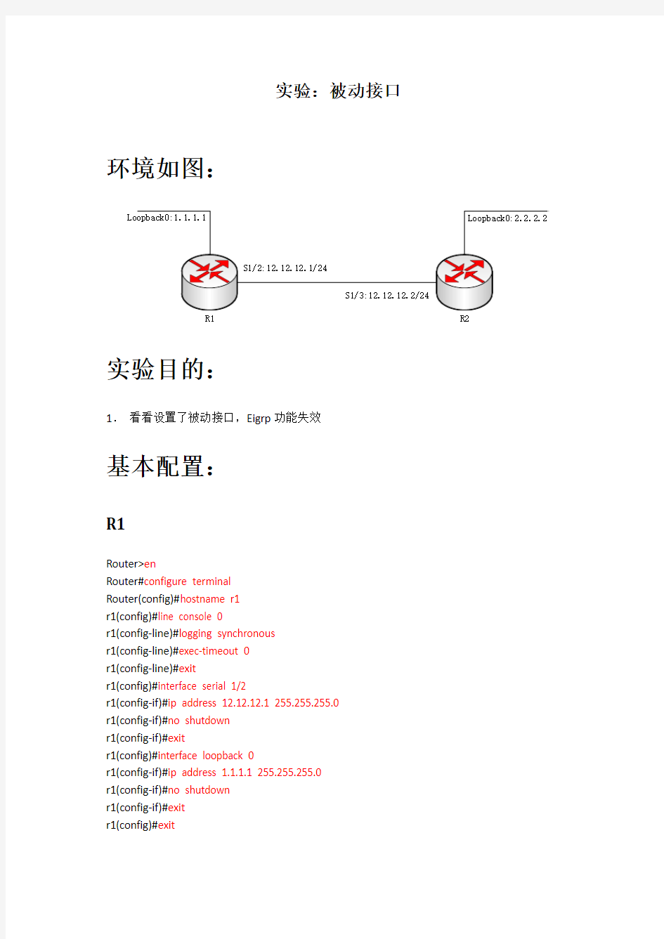
环境如图:
R1R2实验目的:
1.看看设置了被动接口,Eigrp功能失效
基本配置:
R1
Router>en
Router#configure terminal
Router(config)#hostname r1
r1(config)#line console 0
r1(config-line)#logging synchronous
r1(config-line)#exec-timeout 0
r1(config-line)#exit
r1(config)#interface serial 1/2
r1(config-if)#ip address 12.12.12.1 255.255.255.0
r1(config-if)#no shutdown
r1(config-if)#exit
r1(config)#interface loopback 0
r1(config-if)#ip address 1.1.1.1 255.255.255.0
r1(config-if)#no shutdown
r1(config-if)#exit
r1(config)#exit
r1#wr
R2
Router>enable
Router#configure terminal
Router(config)#hostname r2
r2(config)#line console 0
r2(config-line)#logging synchronous
r2(config-line)#exec-timeout 0
r2(config-line)#exit
r2(config)#interface serial 1/3
r2(config-if)#ip address 12.12.12.2 255.255.255.0
r2(config-if)#no shutdown
r2(config-if)#exit
r2(config)#interface loopback 0
r2(config-if)#ip address 2.2.2.2 255.255.255.0
r2(config-if)#no shutdown
r2(config-if)#exit
r2(config)#exit
r2#wr
配置EIGRP动态路由协议R1
r1#configure terminal
r1(config)#router eigrp 1
r1(config-router)#network 1.1.1.1 0.0.0.255
r1(config-router)#network 12.12.12.1 0.0.0.155
r1(config-router)#no auto-summary
r1(config-router)#exit
r1(config)#exit
R2
r2#configure terminal
r2(config)#router eigrp 1
r2(config-router)#network 2.2.2.2 0.0.0.255
r2(config-router)#network 12.12.12.2 0.0.0.255
r2(config-router)#no auto-summary
r2(config-router)#exit
r2(config)#exit
显示路由表
R1
r1#show ip route
Codes: C - connected, S - static, R - RIP, M - mobile, B - BGP
D - EIGRP, EX - EIGRP external, O - OSPF, IA - OSPF inter area
N1 - OSPF NSSA external type 1, N2 - OSPF NSSA external type 2
E1 - OSPF external type 1, E2 - OSPF external type 2
i - IS-IS, su - IS-IS summary, L1 - IS-IS level-1, L2 - IS-IS level-2
ia - IS-IS inter area, * - candidate default, U - per-user static route
o - ODR, P - periodic downloaded static route
Gateway of last resort is not set
1.0.0.0/24 is subnetted, 1 subnets
C 1.1.1.0 is directly connected, Loopback0
D 2.0.0.0/8 [90/2297856] via 12.12.12.2, 00:00:55, Serial1/2
12.0.0.0/30 is subnetted, 1 subnets
C 12.12.12.0 is directly connected, Serial1/2
R2
r2#show ip route
Codes: C - connected, S - static, R - RIP, M - mobile, B - BGP
D - EIGRP, EX - EIGRP external, O - OSPF, IA - OSPF inter area
N1 - OSPF NSSA external type 1, N2 - OSPF NSSA external type 2
E1 - OSPF external type 1, E2 - OSPF external type 2
i - IS-IS, su - IS-IS summary, L1 - IS-IS level-1, L2 - IS-IS level-2
ia - IS-IS inter area, * - candidate default, U - per-user static route
o - ODR, P - periodic downloaded static route
Gateway of last resort is not set
1.0.0.0/24 is subnetted, 1 subnets
D 1.1.1.0 [90/2297856] via 12.12.12.1, 00:00:12, Serial1/3
2.0.0.0/8 is variably subnetted, 2 subnets, 2 masks
C 2.2.2.0/24 is directly connected, Loopback0
D 2.0.0.0/8 is a summary, 00:00:13, Null0
12.0.0.0/8 is variably subnetted, 2 subnets, 2 masks
C 12.12.12.0/30 is directly connected, Serial1/3
D 12.0.0.0/8 is a summary, 00:00:13, Null0
在R1上做被动接口
R1
r1#configure terminal
r1(config)#router eigrp 1
r1(config-router)#passive-interface serial 1/2
r1(config-router)#exit
r1(config)#exit
查看结果
R1
r1#show ip route
Codes: C - connected, S - static, R - RIP, M - mobile, B - BGP
D - EIGRP, EX - EIGRP external, O - OSPF, IA - OSPF inter area
N1 - OSPF NSSA external type 1, N2 - OSPF NSSA external type 2
E1 - OSPF external type 1, E2 - OSPF external type 2
i - IS-IS, su - IS-IS summary, L1 - IS-IS level-1, L2 - IS-IS level-2
ia - IS-IS inter area, * - candidate default, U - per-user static route
o - ODR, P - periodic downloaded static route
Gateway of last resort is not set
1.0.0.0/24 is subnetted, 1 subnets
C 1.1.1.0 is directly connected, Loopback0
12.0.0.0/30 is subnetted, 1 subnets
C 12.12.12.0 is directly connected, Serial1/2
R2
r2#show ip route
Codes: C - connected, S - static, R - RIP, M - mobile, B - BGP
D - EIGRP, EX - EIGRP external, O - OSPF, IA - OSPF inter area
N1 - OSPF NSSA external type 1, N2 - OSPF NSSA external type 2
E1 - OSPF external type 1, E2 - OSPF external type 2
i - IS-IS, su - IS-IS summary, L1 - IS-IS level-1, L2 - IS-IS level-2
ia - IS-IS inter area, * - candidate default, U - per-user static route
o - ODR, P - periodic downloaded static route
Gateway of last resort is not set
2.0.0.0/8 is variably subnetted, 2 subnets, 2 masks
C 2.2.2.0/24 is directly connected, Loopback0
D 2.0.0.0/8 is a summary, 00:05:23, Null0
12.0.0.0/8 is variably subnetted, 2 subnets, 2 masks
C 12.12.12.0/30 is directly connected, Serial1/3
D 12.0.0.0/8 is a summary, 00:05:23, Null0
因为R1的Serial1/2接口设置成了被动接口,无法正常收发Eigrp数据包。因此Eigrp的邻居关系也就断了,无法正常更新动态路由表了。
EIGRP和RIP单播实验 试验拓扑图如下: 根据拓扑图,做好相应基本配置并启用EIGRP协议 一 RA(config)#router eigrp 99 RA(config-router)#passive-int s1/0 *Aug 8 03:25:24.827: %DUAL-5-NBRCHANGE: IP-EIGRP(0) 99: Neighbor 12.1.1.2 (Seria l1/0) is down: interface passive RA#show ip eig nei IP-EIGRP neighbors for process 99 将RTA的s1/0接口被动掉并查看邻居表,发现此时邻居表为空,即A丢失与B的邻居关系,为了得到更详细的信息,查看一下Hello包的发送情况RA#debug eigrp packets EIGRP Packets debugging is on (UPDATE, REQUEST, QUERY, REPLY, HELLO, IPXSAP, PROBE, ACK, STUB, SIAQUE RY, SIAREPLY) RA# *Aug 8 03:27:51.179: EIGRP: Sending HELLO on Loopback0 *Aug 8 03:27:51.179: AS 99, Flags 0x0, Seq 0/0 idbQ 0/0 iidbQ un/rely 0/0 *Aug 8 03:27:51.179: EIGRP: Received HELLO on Loopback0 nbr 1.1.1.1 *Aug 8 03:27:51.179: AS 99, Flags 0x0, Seq 0/0 idbQ 0/0 *Aug 8 03:27:51.179: EIGRP: Packet from ourselves ignored RA# *Aug 8 03:27:55.747: EIGRP: Sending HELLO on Loopback0 *Aug 8 03:27:55.747: AS 99, Flags 0x0, Seq 0/0 idbQ 0/0 iidbQ un/rely 0/0 *Aug 8 03:27:55.747: EIGRP: Received HELLO on Loopback0 nbr 1.1.1.1 *Aug 8 03:27:55.747: AS 99, Flags 0x0, Seq 0/0 idbQ 0/0 *Aug 8 03:27:55.747: EIGRP: Packet from ourselves ignored 发现此时RTA在接口s1/0上既不能发送也不能接受Hello包,测试一下RTA到RTB环回接口的连通性 RA#ping 2.2.2.2 Type escape sequence to abort. Sending 5, 100-byte ICMP Echos to 2.2.2.2, timeout is 2 seconds: .....
CISCO Vlan配置实例 如何配置三层交换机创建VLAN 以下的介绍都是基于Cisco交换机的VLAN。Cisco的VLAN实现通常是以端口为中心的。与节点相连的端口将确定它所驻留的VLAN。将端口分配给VLAN的方式有两种,分别是静态的和动态的。形成静态VLAN的过程是将端口强制性地分配给VLAN的过程。即我们先在VTP (VLAN Trunking Protocol)Server上建立VLAN,然后将每个端口分配给相应的VLAN的过程。这是我们创建VLAN最常用的方法。动态VLAN形成很简单,由端口决定自己属于哪个VLAN。即我们先建立一个VMPS(VLAN Membership Policy Server)VLAN管理策略服务器,里面包含一个文本文件,文件中存有与VLAN映射的MAC地址表。交换机根据这个映射表决定将端口分配给何种VLAN。这种方法有很大的优势,但是创建数据库是一项非常艰苦而且非常繁琐的工作。下面以实例说明如何在一个典型的快速以太局域网中实现VLAN。所谓典型的局域网就是指由一台具备三层交换功能的核心交换机接几台分支交换机(不一定具备三层交换能力)。我们假设核心交换机名称为:COM;分支交换机分别为:PAR1、PAR2、PAR3……,分别通过Port 1的光线模块与核心交换机相连;并且假设VLAN名称分别为COUNTER、MARKET、MANAGING…… 设置VTP DOMAIN VTP DOMAIN 称为管理域。交换VTP更新信息的所有交换机必须配置为相同的管理域。如果所有的交换机都以中继线相连,那么只要在核心交换机上设置一个管理域,网络上所有的交换机都加入该域,这样管理域里所有的交换机就能够了解彼此的VLAN列表。COM#vlan database 进入VLAN配置模式 COM(vlan)#vtp domain COM 设置VTP管理域名称COM COM(vlan)#vtp server 设置交换机为服务器模式 PAR1#vlan database 进入VLAN配置模式 PAR1(vlan)#vtp domain COM 设置VTP管理域名称COM PAR1(vlan)#vtp Client 设置交换机为客户端模式 PAR2#vlan database 进入VLAN配置模式 PAR2(vlan)#vtp domain COM 设置VTP管理域名称COM PAR2(vlan)#vtp Client 设置交换机为客户端模式 PAR3#vlan database 进入VLAN配置模式 PAR3(vlan)#vtp domain COM 设置VTP管理域名称COM PAR3(vlan)#vtp Client 设置交换机为客户端模式 注意:这里设置交换机为Server模式是指允许在本交换机上创建、修改、删除VLAN及其他一些对整个VTP域的配置参数,同步本VTP域中其他交换机传递来的最新的VLAN信息;Client 模式是指本交换机不能创建、删除、修改VLAN配置,也不能在NVRAM中存储VLAN配置,但可以同步由本VTP域中其他交换机传递来的VLAN信息。 配置中继为了保证管理域能够覆盖所有的分支交换机,必须配置中继。Cisco交换机能够支持任何介质作为中继线,为了实现中继可使用其特有的ISL标签。ISL(Inter-Switch Link)是一个在交换机之间、交换机与路由器之间及交换机与服务器之间传递多个VLAN信息及VLAN数据流的协议,通过在交换机直接相连的端口配置ISL封装,即可跨越交换机进行整个网络的VLAN分配和进行配置。 在核心交换机端配置如下: COM(config)#interface gigabitEthernet 2/1 COM(config-if)#switchport
创建高级交换型互联网实验报告 时间:2011-4-27 实验名称:Eigrp末节路由设置 班级计算机通信2班32号姓名黄跃实验内容 1、拓扑图: 实验步骤: ?1、配置R1、R2、R3的IP地址和名称 ?R0 ?Router>en ?Router#config t ?Router(config)#HO R0 ?R0(config)#in s0/0 ?R0(config-if)#clock rate 64000 ?R0(config-if)#ip add 10.1.1.1 255.255.255.252 ?R0(config-if)#no shu ?R0(config-if)#in lo 1 ?R0(config-if)#ip add 11.11.11.11 255.255.255.255 ?R0(config-if)#in lo 2 ?R0(config-if)#ip add 172.16.9.1 255.255.255.0 ?R0(config-if)#in lo 3 ?R0(config-if)#ip add 172.16.10.1 255.255.255.0 ?R0(config-if)#in lo 4 ?R0(config-if)#ip add 172.16.11.1 255.255.255.0 ?R0(config-if)#in lo 5 ?R0(config-if)#ip add 172.16.12.1 255.255.255.0 ? ?R1 Router>en Router#config t
Router(config)#HO R1 R1(config)#in s0/0 R1(config-if)#ip add 10.1.1.2 255.255.255.252 R1(config-if)#no shu R1(config-if)#in fa0/0 R1(config-if)#ip add 10.1.1.9 255.255.255.252 R1(config-if)#no shu R1(config-if)#in lo 1 ?R2(config-if)#ip add 22.22.22.22 255.255.255.255 ? R2 Router>en Router#config t Enter configuration commands, one per line. End with CNTL/Z. Router(config)#HO R3 R2(config)#in fa0/0 R2(config-if)#ip add 10.1.1.10 255.255.255.252 R2(config-if)#no shu R2(config-if)#in lo 1 R2(config-if)#ip add 33.33.33.33 255.255.255.255 ?2、在R0、R1、R2上启用EIGRP协议 ?R0 ?R0(config-if)#router eigrp 90 ?R0(config-router)#no au ?R0(config-router)#net 10.1.1.0 0.0.0.3 ?R0(config-router)#net 172.16.9.0 0.0.0.255 ?R0(config-router)#net 172.16.10.0 0.0.0.255 ?R0(config-router)#net 172.16.11.0 0.0.0.255 ?R0(config-router)#net 172.16.12.0 0.0.0.255 ?R0(config-router)#net 11.11.11.11 0.0.0.0 ? ?R1 ?R1(config-if)#router eigrp 90 ?R1(config-router)#no au ?R1(config-router)#net 10.1.1.0 0.0.0.3 ?R1(config-router)#net 10.1.1.8 0.0.0.3 ?R1(config-router)#net 22.22.22.22 0.0.0.0 ? ?R2 ?R2(config-if)#router eigrp 90 ?R2(config-router)#no au ?R2(config-router)#net 10.1.1.8 0.0.0.3 ?R2(config-router)#net 33.33.33.33 0.0.0.0 ? ?3、在R0上配置手动汇总(关闭自动汇总) ?R0(config-router)#in s0/0
EIGRP综合实验2 配置要点 ●帧中继交换机以及PVC的配置 ●帧中继多点子接口配置 ●帧中继点对点子接口配置 ●EIGRP基本配置(包括静态邻居的配置) ●NTP配置 ●EIGRP认证配置 实验拓扑 配置概述 ●在FRSW上配置帧中继交换机,PVC的设计如下: ?R41--S1/0--S1/0.12------412------S1/0--FRSW--S1/1------421------S1/0--R42; ?R41--S1/0--S1/0.12------415------S1/0--FRSW--S1/3------451------S1/0--R45; ?R41--S1/0--S1/0.14------414------S1/0--FRSW--S1/2------441------S1/0--R44;
●各站点的IP地址设计如下: ?R41--S1/0--S1/0.12--172.14.12.41/24------172.14.12.42/24--S1/0--R42; ?------172.14.12.45/24--S1/0--R45; ?R41--S1/0--S1/0.14--172.14.14.41/24------172.14.14.44/24--S1/0--R44; ●EIGRP的基本配置,包括静态邻居的配置; ●NTP的配置: ?把R41配置为NTP的服务器; ?把R42、R45和R44配置为NTP的客户端 ●以R41为中心与其他各个站点(R42、R45和R44)配置EIGRP认证。
FRSW3(config-if)#frame intf-type dce FRSW3(config-if)#frame route 441 int s 1/0 414 FRSW3(config-if)#no sh FRSW3(config-if)#^Z FRSW3# 配完之后看看接口 继续点对点子接口的配置 R41(config)#int s 1/0.14 ? multipoint Treat as a multipoint link point-to-point Treat as a point-to-point link
Cisco路由器静态路由配置实例 初学路由器的配置,下面就用Boson NetSim for CCNP 6.1模拟软件进行配置…这篇文章主要是对路由表进行静态路由配置… 拓扑结构图如下: 下面开始: 1.对Router1进行配置,配置命令如下: Router>enable进入特权模式 Router#configure terminal 进入配置模式 Enter configuration commands, one per line. End with CNTL/Z. Router(config)#interface ethernet0 进入E0端口模式
Router(config-if)#ip address 192.168.1.1 255.255.255.0 配置IP地址Router(config-if)#no shutdown 激活该端口 %LINK-3-UPDOWN: Interface Ethernet0, changed state to up Router(config-if)#exit 返回上一级 Router(config)#interface serial0 进入S0 端口模式 Router(config-if)#ip address 192.168.2.1 255.255.255.0 Router(config-if)#no shutdown %LINK-3-UPDOWN: Interface Serial0, changed state to up %LINK-3-UPDOWN: Interface Serial0, changed state to down %LINEPROTO-5-UPDOWN: Line protocol on Interface Serial0, changed state to down Router(config-if)#clock rate 6400 注意这里是设置时钟..如有不明白,可以打”?”.但是系统给的参数是 64000 .而我们要配置成 6400 ..可能是模拟软件的一个小BUG 吧!现在是在模拟软件中,如果是真实环境,我们要参照说 明书..按照说明书来配置参数…. Router(config-if)#exit Router(config)#ip route 192.168.3.0 255.255.255.0 192.168.2.2 配置路由表
EIGRP 路由协议的配置 一.实验目的 掌握路由器EIGRP 路由协议的配置方法。 二.实验要点 通过对路由器A和路由器B启用EIGRP路由协议,使路由器A可Ping通路由器B所连的各个网络, 反之,亦然。 三.实验设备 路由器Cisco 2621两台,交换机Cisco 2950两台,带有网卡的工作站PC 至少两台。 四.实验环境 S0/0:10.0.0.1/24 S0/0:10.0.0.2/24 F0/0:192.168.0.1/24 F0/0:192.168.1.1/24 Host A Host B IP Address:192.168.0.2/24 IP Address:192.168.1.2/24 Default Gateway:192.168.0.1 Default Gateway:192.168.1.1 图13 EIGRP 路由协议的配置 五.实验步骤 1. 如图对路由器A 及路由器B 的各个接口配置好IP地址 l 在路由器A (假设为DCE 端)上 router>en router#conf t
router(config)#hostname RouterA RouterA(config)#int s0/0 RouterA(config-if)#ip add 10.0.0.1 255.255.255.0 RouterA(config-if)#cl ra 64000 RouterA(config-if)#no sh RouterA(config)#int f0/0 RouterA(config-if)#ip add 192.168.0.1 255.255.255.0 RouterA(config-if)#no sh RouterA(config-if)#exit l 在路由器B (假设为DTE 端)上 router>en router#conf t router(config)#hostname RouterB RouterB(config)#int s0/0 RouterB(config-if)#ip add 10.0.0.2 255.255.255.0 RouterB(config-if)#no sh RouterB(config)#int f0/0 RouterB(config-if)#ip add 192. 168.1.1 255.255.255.0 RouterB(config-if)#no sh RouterB(config-if)#exit 实验结果: a. 在路由器A 上是否能ping 通路由器B 的串口S0/0 (10.0.0.2) b. 在路由器A 上是否能ping 通路由器B 的以太口F0/0 (192.168.1.1) 2. 在路由器A 和路由器B 上分别配置EIGRP 路由协议 在路由器A 上: RouterA (config)#router eigrp 100 RouterA(config-router)# net 10.0.0.0 RouterA(config-router)# net 192.168.0.0 在路由器B 上: RouterB (config)# router eigrp 100 RouterB(config-router)# net 10.0.0.0 RouterB(config-router)# net 192.168.1.0 实验结果: a. 在路由器A 上是否能ping 通路由器B 的串口S0/0 (10.0.0.2) b. 在路由器A 上是否能ping 通路由器B 的以太口F0/0
E I G R P协议
EIGRP EIGRP简单实例 EIGRP:Enhanced Interior Gateway Routing Protocol 即增强网关内部路由线路协议。也翻译为加强型内部网关路由协议。 EIGRP是Cisco公司的私有 协议。Cisco公司是该协议的发明者和唯一具备该协议解释和修改权的厂商。EIGRP结合了链路状态和距离矢量型路由选择协议的Cisco专用协议,采用弥 散修正算法(DUAL)来实现快速收敛,可以不发送定期的路由更新信息以减少带宽的占用,支持Appletalk、IP、Novell和NetWare等多种网络层协议。EIGRP路由协议简介 是Cisco的私有路由协议,它综合了距离矢量和链路状态2者的优点,它的特点包括: 1.快速收敛 链路状态包(Link-State Packet,LSP)的转发是不依靠路由计算的,所以大型网络可以较为快速的进行收敛.它只宣告链路和链路状态,而不宣告路由,所以即使链路发生了变化,不会引起该链路的路由被宣告.但是链路状态路由协议使用的是Dijkstra算法,该算法比较复杂,并且较占CPU和内存资源和 其他路由协议单独计算路由相比,链路状态路由协议采用种扩散计算(diffusingcomputations ),通过多个路由器并行的记性路由计算,这样就可以在无环路产生的情况下快速的收敛.
2.减少带宽占用 EIGRP不作周期性的更新,它只在路由的路径和度发生变化以后做部分更新.当路径信息改变以后,DUAL只发送那条路由信息改变了的更新,而不是发 送整个路由表.和更新传输到一个区域内的所有路由器上的链路状态路由协 议相比,DUAL只发送更新给需要该更新信息的路由器。在WAN低速链路 上,EIGRP可能会占用大量带宽,默认只占用链路带宽50%,之后发布的IOS允许使用命令ip bandwidth-percent eigrp来修改这一默认值 . 3.支持多种网络层协议 EIGRP通过使用“协议相关模块”(即protocol- dependentmodule
《作业:配置RIPv2与EIGRP》 一、实验拓扑 二、实验要求 1、按照实验拓扑配置IP地址。 2、配置RIPv2,实现总部与分部内网之间能够相互通信。 3、配置EIGRP,实现总部与分部内网之间能够相互通信。 三、实验步骤 配置各路由器所需IP: R1的配置: R1(config-if)#ip add 192.168.1.1 255.255.255.0 R1(config-if)#no shu R1(config-if)#int f0/0 R1(config-if)#ip add 10.2.2.1 255.255.255.0 R1(config-if)#no shu R1(config)#int f0/1 R1(config-if)#ip add 10.3.3.1 255.255.255.252 R1(config-if)#no shu R1#show pint brief Interface IP-Address OK? Method Status Protocol FastEthernet0/0 10.2.2.1 YES manual up up FastEthernet0/1 10.3.3.1 YES manual up up Loopback0 192.168.1.1 YES manual up up R2的配置: R2(config)#int lo 1 R2(config-if)#ip add 192.168.2.1 255.255.255.0 R2(config-if)#no shu R2(config-if)#int f0/0 R2(config-if)#ip add 10.2.2.2 255.255.255.252 R2(config-if)#no shu R2#show pint brief Interface IP-Address OK? Method Status Protocol
基础知识点: EIGRP的metric计算 有K1(带宽)、K2(负载)、K3(延迟)、K4(可靠性)、K5(MTU)五个参数,默认情况下k值如下:K1=K3=1;K2=K4=K5=0 metric=256*(10000000/K1*bandwidth(kbit/s)+ total delay/10) BW和DLY值都可以在接口模式下手工指定,使用delay值时是tens of microseconds,在show interface 时实际值要乘以10. 使用metric weights 可以修改k值;但同一自制系统内的所有K值必须一致。 BW和DLY值可以使用show interface命令查看如 Ethernet0/1 is up, line protocol is up Hardware is AmdP2, address is cc00.0ffc.0001 (bia cc00.0ffc.0001) Internet address is 192.168.4.1/24 MTU 1500 bytes, BW 10000 Kbit, DLY 1000 usec, reliability 255/255, txload 1/255, rxload 1/255 Encapsulation ARPA, loopback not set Keepalive set (10 sec) ARP type: ARPA, ARP Timeout 04:00:00 Last input 00:00:02, output 00:00:01, output hang never Last clearing of "show interface" counters never Input queue: 0/75/0/0 (size/max/drops/flushes); Total output drops: 0 Queueing strategy: fifo Output queue: 0/40 (size/max) 5 minute input rate 0 bits/sec, 0 packets/sec 5 minute output rate 0 bits/sec, 0 packets/sec 816 packets input, 75702 bytes, 0 no buffer Received 808 broadcasts, 0 runts, 0 giants, 0 throttles 0 input errors, 0 CRC, 0 frame, 0 overrun, 0 ignored 0 input packets with dribble condition detected 1172 packets output, 97655 bytes, 0 underruns 0 output errors, 0 collisions, 1 interface resets 0 babbles, 0 late collision, 0 deferred 0 lost carrier, 0 no carrier 0 output buffer failures, 0 output buffers swapped out total delay可以通过show ip route x.x.x.x 查看到:如 RC#show ip route 192.168.3.0 Routing entry for 192.168.3.0/24 Known via "eigrp 100", distance 90, metric 307200, type internal Redistributing via eigrp 100 Last update from 192.168.4.2 on Ethernet0/1, 00:36:32 ago
RIPv2配置实例 1.用户需求: 某企业总部计划和它的2个分公司联网。计划采用2条数字链路连接总部和分公司,并要求总部和分公司的IP网络段不能相同,并且划分广播域隔离广播;不采用三层交换设备;两个分公司联网后能够互相访问;总部和分公司联网后路由器能够自动学习。 2.方案分析与解决: 不采用三层交换技术,但要求采用数字链路,可以考虑用路由器。 3.网络拓扑: 4.规划网络地址: PC1:192.168.3.2 255.255.255.0 192.168.3.1 PC2:192.168.3.3 255.255.255.0 192.168.3.1 PC3:192.168.4.2 255.255.255.0 192.168.4.1 PC4:192.168.5.2 255.255.255.0 192.168.5.1 总部路由器A:F0/0:192.168.3.1 255.255.255.0 S1/0:192.168.1.1 255.255.255.0 S1/1:192.168.2.1 255.255.255.0 分公司路由器B:F0/0:192.168.4.1 255.255.255.0 S1/0:192.168.1.2 255.255.255.0 分公司路由器C:F0/0:192.168.5.1 255.255.255.0 S1/1:192.168.2.2 255.255.255.0 5.路由器配置: 总部A: Router>en Router#conf t Enter configuration commands, one per line. End with CNTL/Z. Router(config)#hostname routerA
本次讲解路由器eigrp协议的配置: [1]EIGRP与IGRP在network命令的区别在于多了wildcard-mask参数,这是通配符掩码。如果网络定义使用的是默认掩码,则wildcard-mask参数可以省略:如果网络定义使用的不是默认掩码,则wildcard-mask参数必须标明。 [2]EIGRP在处理有类别(A、B、C类)网络地址时,会自动地汇总路由。这意味着即使规定RTC 连接的是10.0.3.0/24这个网络,但EIGRP仍然会发布其连接整个A类网络10.0.0.0。在EIGRP中,路由自动汇总功能默认是有效的。存在不连续子网的网络中,通常需要用no auto-summary命令来关闭该功能。 本例配置模型图 命令行: RA配置命令: Router> Router>enable Router#conf t
Enter configuration commands, one per line. End with CNTL/Z. ^ Router(config)#router eigrp 100 //使用eigrp协议。使用系统自制号100 Router(config-router)#network 202.1.1.5 0.0.0.3 //指定与该路由器直接相连的网络Router(config-router)#network 192.1.1.0 0.0.0.255 //指定与该路由器直接相连的网络Router(config-router)#no auto-summary //关闭自动汇总功能 Router(config-router)#exit Router(config)#int s1/0 Router(config-if)#ip address 202.1.1.5 255.255.255.252 //依照图配置IP Router(config-if)#clock rate 64000 //使用时钟频率 Router(config-if)#bandwidth 64 Router(config-if)#no shutdown %LINK-5-CHANGED: Interface Serial1/0, changed state to down Router(config-if)#exit Router(config)#int f0/0 //依照图配置IP Router(config-if)#ip address 192.1.1.1 255.255.255.0 Router(config-if)#no shutdown %LINK-5-CHANGED: Interface FastEthernet0/0, changed state to up %LINEPROTO-5-UPDOWN: Line protocol on Interface FastEthernet0/0, changed state to up Router(config-if)#exit Router(config)#exit Router# %SYS-5-CONFIG_I: Configured from console by console Router#wr Building configuration... [OK] Router#
EIGRP基本配置实验 一、实验目的 1.掌握EIGRP基本原理 2.掌握EIGRP基本配置 3.掌握EIGRP的验证配置 4.了解EIGRP的简单测试 二、实验拓扑图 三、实验内容 -配置IP地址实现直连互通 -在所有的路由器上配置EIGRP ,AS号位100, -查看R2的路由表和邻居表,并分析路由表中EIGRP路由条目的度量值的计算过程
-R1-R2之间启用EIGRP密文验证,密钥位KEY 12,KEY-STRING-QM_CCNA *若在路由表中出现汇总路由,建议在每一台路由器上配置 R1(config-if)#router eigrp 1 R1(config-router)#no auto-summary 四、实验具体操作截图 1.配置IP地址实现直连互通 (1)为R1配置IP地址 (2)为R2配置IP地址
(3)为R3配置IP地址 (4)验证是否直连互通 结果:可以直连互通 2.在所有的路由器上配置EIGRP ,AS号位100
3.查看R2的路由表和邻居表,并分析路由表中EIGRP路由条目的 度量值的计算过程。 (1)查看R2的路由表和邻居表 (2)分析路由表中路由条目的度量值的计算过程 Metric=[10^7/BW+延时总和/10US]*256 在R2的路由表中,根据度量值计算公式: Metric=[10^7/100+(5000+100)/10US]*256=156160 其中f口的最小带宽是100M,总延时为Loopback口的延时5000加上经过路由器F口的延时100之和。 注:对于计算度量值时,才开始总是算不对,将loopback口的延时当做是100,怎么算都不对,百思不得其解,最后上网查找,得知loopback口环路默认延时是5000,最终计算出的度量值与路由表中的度量值相等。
EIGRP命令列表 ---------------- ◆{Router(config)#router eigrp [AS号]} 开启EIGRP路由协议 ◆{Router(config-router)#network [子网号]} 配置EIGRP子网 ◆{Router(config-router)#network [子网号] [掩码]} 配置EIGRP无类子网 ◆{no auto-summary} 关闭有类自动汇总 ◆{ip summary-address [AS号] [IP地址] [掩码]} 手动配置汇总 ◆{eigrp stub} 配置一个末梢路由 ◆{variance} 配置一个不平衡的均衡负载 ◆{ip hello-interval eigrp [AS号] [时间/s]} 改变Hello包发送频率 ◆{ip hold-time eigrp [AS号] [时间/s]} 改变Hold-Time长度 ◆{bandwidth} 改变一个接口上的带宽,最大化带宽将限制它自身的通路 ◆{ip bandwidth-percent eigrp [AS号]} 改变EIGRP通路使用的带宽。默认为50% ◆{Router(config)#interface s0 Router(config-if)#ip summary-address eigrp [AS号] [IP地址] [掩码]} 手工配置汇总 ◆{Router(config-router)#eigrp stub [receive-only | connected | redistributed | static | summary]} 配置末梢路由 ◆{Router(config-route)#variance multiplier} 配置不等开销负载均衡 ◆{Rout er(config-if)#ip hello-interval eigrp [AS号] [时间]} 配置Hello计时器 ◆{Router(config-if)#ip hold-time eigrp [AS号] [时间]} 配置Hold计时器 ◆{Router(config-if)#ip authentication mode eigrp [AS号] md5} 起用EIGRP的MD5认证 ◆{Router(config-if)#ip anthentication key-chain eigrp [AS号] [chain-name]} 配置MD5密匙 ◆{Router(config)#key chain [chain-name] Router(config-if)#key [key-id] Router(config-keychain-key)#key-string [key]}
回顾昨天:提问:1、RIP默认几条线路做负载均衡,最大支持几条2、RIP路由协议的配置命令是什么?有几步?3、RIP协议发送UPDATE包的周期间隔是多少?多长时间后激发保持状态?保持时间持续多久? 今天内容:IGRP路由协议的特性及配置方法。及相关实验 首先应该确认的是IGRP虽然有较先进的算法计算自己的度量值来计算路由。但它仍是路离矢量路由协议的一种。 一、此协议计算度量值的算法比较复杂。综合考虑链路带宽(bandwidth)、延迟(delay)、负载(loading)、可靠性(reliability) 最大传输单元(mtu)等,默认的算法是链路上的带宽加上设备的延迟。 二、IGRP也是默认四条线路做负载均衡,最大支持六条。但与RIP不同的是能用不等开销的链路做负载。 三、IGRP路由协议使用广播方式每隔90秒发送一次UPDATE包。如果在270秒内没有收到该升级包,则认为邻居路由器崩
溃。所有从这个路由器学到的路由都进入保持状态,保持时间是280秒。过了这个时间则丢弃那些路由条目。 四、IGRP协议的配置(图10-25) 配置方法与RIP的方法类似。先在运行IGRP 协议的路由器上声明使用该协议。 此时注意有一个100,这个为自治域系统号,(在实际工程中此号由电信指定)通常在我们现在阶段讨论的网络问题中都是在同自治域中的所以,此号在相邻路由器上配置要一样。然后发布直连的网段。 五、检查IGRP的配置正确性 看图(10-30)与(10-27)的区别。 Eigrp路由协议的原理 一、概述 它是一种混合型的路由协议,在路由的学习上具有链路状态路由的特点,在计算路径的度量值时又具有距离矢量路由协议的特点。但它是一种增强的IGRP,是由其研发而来,所以CISCO经常把EIGRP协议归属于距离矢量路由协议。称它为先进的距离矢量路由协议。由于是私有协议所以限制了在电信运营商的网络上使用。但在一些大型企业里,得到了普遍的应用。 虽然是从IGRP发展而来,但不同的是,支持VLSM和CIDR,收敛更为迅速,可扩展性更好,更高效的处理路由环路等问题。
配置EEM监测内存使用率: Router(config)#event manager applet MEM Router(config-applet)#event snmp oid 1.3.6.1.4.1.9.9.48.1.1.1.6.1 get-type exact entry-op lt entry-val 30623072 poll-interval 90 Router(config-applet)#action 01.0 cli command "enable" Router(config-applet)#action 02.0 cli command "conf t" Router(config-applet)#action 03.0 cli command "router eigrp 100" Router(config-applet)#exit 说明:EEM当前监测内存的使用情况,如果空闲大小低于30623072,则事件被触发,采集间 隔为90秒一次,如果事件触发后,执行的第一个动作为在命令行下输入命令enable,执行的 第二个动作为在命令行下输入命令conf t,执行的第三个动作为在命令行下输入命令router eigrp 100,其实结果就是在事件发生后,自动启用一个EIGRP进程,AS号为100;结合之前 可以得知,内存总大小为30623072,所以内存空闲空间肯定会小于30623072,那么该EEM policy配置后,事件肯定是被触发的。其中动作标签为01.0格式。 event manager applet dump-procs event syslog pattern "CPUALERT5MIN" action 001 cli command "enable" action 002 cli command "show proc cpu sorted 5min" action 003 set lines 0 action 004 foreach line "$_cli_result" "\n" action 005 if$lines gt 11 action 006 break action 007 end action 008 append output $line action 009 increment lines action 010 end action 011 mail to engineer@https://www.doczj.com/doc/523365782.html, from EEM@https://www.doczj.com/doc/523365782.html, server 198.2.5.10 subject "CPUALERT5MIN" body "$output" ======================================================================= event manager applet dump-procs event syslog pattern "CPURISINGTHRESHOLD" action 001 cli command "enable" action 002 cli command "show proc cpu sorted 5min" action 003 set lines 0 action 004 foreach line "$_cli_result" "\n"