M44C510E中文资料
- 格式:pdf
- 大小:527.49 KB
- 文档页数:60

Data SheetFUJITSU PRIMERGY CX400 M4 多節點伺服器專為工作負載設計的模組機架式電源FUJITSU PRIMERGY伺服器能執行任何工作負載與因應瞬息萬變的業務需求。
隨著業務拓展,對於應用的需求也隨之升高。
每項需求均需佔用資源,因此必須尋找能夠優化運算的方式,為使用者提供更佳服務。
PRIMERGY系統具備完整的產品組合,包含適用於遠端分公司的PRIMERGY直立式伺服器、萬用機架式伺服器,以及密度最佳化的多節點伺服器,有助於提升運算能力,配合業務需求。
經得起商業考驗的創新系列產品,以其高效率降低營運的成本與複雜程度,使日常運作更加靈活,並可無縫整合,助您專注在核心業務上。
FUJITSU PRIMERGY CX多節點系統是雲端、超融合式與高效能運算解決方案的理想平台,提供資料中心與分公司大量的運算效能,以執行虛擬化環境、複雜運算、伺服器整併及高可用性情境。
PRIMERGY CX400 M4FUJITSU PRIMERGY CX400 M4提供可擴充的IT架構,以其高度靈活性幫助企業及研究機構快速因應劇烈的挑戰。
CX400 M4為適用於FUJITSU多節點系統的模組機箱,結合類刀鋒伺服器的密度、效率,以及機架式伺服器的簡潔與成本優勢。
2U機箱使企業得以依照業務需求,逐步增加或移除至多4個節點。
此款機箱容許節點與組件共享電源、冷卻與管理資源,具備熱插拔與備援電源供應器、熱插拔與備援風扇模組,並可容納多達24顆儲存磁碟。
PRIMERGY CX伺服器節點提供虛擬桌面(VDI)、架構虛擬化、高效能與技術運算、網路服務、雲端運算,亦可作為超融合架構。
Fujitsu ServerView Suite簡化並自動化伺服器產品的週期管理,使IT運作更有效率。
全新ServerView ISM管理軟體可協助管理資料中心與融合架構內的各式硬體資源,並可整合進其他雲端管理系統,涵蓋伺服器、儲存、網路與設備元件管理。

UPC4574G2-E1中⽂资料The information in this document is subject to change without notice. Before using this document, please confirm that this is the latest version.Not all products and/or types are available in every country. Please check with an NEC Electronics sales representative for availability and additional information.DATA SHEETDocument No. G15977EJ4V0DS00 (4th edition)Date Published March 2004 N CP(K) Printed in JapanThe mark shows major revised points.1987DESCRIPTIONThe µPC4574 is an ultra low noise, high slew rate quad operational amplifier specifically designed for audio, instrumentation, and communication circuits. The low noise and high frequency capabilities make it ideal for preamps and active filters for instrumentation and professional audio.FEATURESUltra low noise High slew rate Wide bandwidthInternal frequency compensationORDERING INFORMATIONPart NumberPackageµPC4574C µPC4574C(5) 14-pin plastic DIP (7.62 mm (300)) 14-pin plastic DIP (7.62 mm (300)) µPC4574G2 µPC4574G2(5) 14-pin plastic SOP (5.72 mm (225)) 14-pin plastic SOP (5.72 mm (225))EQUIVALENT CIRCUIT (1/4 Circuit)I I I NVVPIN CONFIGURATION (Top View)OUT 4I I4I N4V ?I N3I I3OUT 3OUT 1I I1I N1V +I N2I I2OUT 2PC4574C, 4574C(5), 4574G2, 4574G2(5)µData Sheet G15977EJ4V0DS2ABSOLUTE MAXIMUM RATINGS (T A = 25°C)Parameter SymbolRatings Unit Voltage between V +and V ? Note1V +V0.3 to +36VDifferential Input Voltage V ID ±30 V Input VoltageNote2V IV ??0.3 to V ++0.3 V Output VoltageNote3V OV ??0.3 to V + +0.3VC Package Note4570 mW Power Dissipation G2 PackageNote5P T 550 mW Output Short Circuit DurationNote610 sec Operating Ambient Temperature T A ?20 to +80 °C Storage TemperatureT stg55 to +125°CNotes 1. Reverse connection of supply voltage can cause destruction.2. The input voltage should be allowed to input without damage or destruction. Even during the transition periodof supply voltage, power on/off etc., this specification should be kept. The normal operation will establish when the both inputs are within the Common Mode Input Voltage Range of electrical characteristics.3. This specification is the voltage which should be allowed to supply to the output terminal from externalwithout damage or destructive. Even during the transition period of supply voltage, power on/off etc., this specification should be kept. The output voltage of normal operation will be the Output Voltage Swing of electrical characteristics.4. Thermal derating factor is –7.6 mW/°C when ambient temperature is higher than 50°C.5. Thermal derating factor is –5.5 mW/°C when ambient temperature is higher than 25°C.6. Pay careful attention to the total power dissipation not to exceed the absolute maximum ratings, Note 4 andNote 5.RECOMMENDED OPERATING CONDITIONSParameter Symbol MIN. TYP. MAX. UnitSupply Voltage V ± ±4 ±16 V Output Current I O±10 mASource Resistance R S 50k ?Capacitive Load (A V = +1)C L 100 pFµPC4574C, µPC4574G2±Notes 7. Input bias currents flow out from IC. Because each currents are base current of PNP-transistor on input stage.8.This current flows irrespective of the existence of use.Data Sheet G15977EJ4V0DS 3µPC4574C(5), µPC4574G2(5)±Notes 7. Input bias currents flow out from IC. Because each currents are base current of PNP-transistor on input stage.8.This current flows irrespective of the existence of use.4Data Sheet G15977EJ4V0DSMEASUREMENT CIRCUITFig.1 Total Harmonic Distortion Measurement CircuitnFig.3 Flat Noise Measurement Circuit (FLAT+JIS A)V O = 40 dB x V n100 V n =V O40 dBData Sheet G15977EJ4V0DS 5Data Sheet G15977EJ4V0DS6TYPICAL PERFORMANCE CHARACTERISTICS (T A = 25°C, TYP.) T A - Operating Ambient Temperature - ?CPOWER DISSIPATIONP T - T o t a l P o w e r D i s s i p a t i o n - m W800600400200020*********20406080100120110010 k 1 M 1 k 10100 k 10 Mf - Frequency - HzOPEN LOOP FREQUENCY RESPONSEA V - O p e n L o o p V o l t a g e G a i n - d BV ± = ±15 V202040608021.510.50?0.5?1?1.5?2T A - Operating Ambient Temperature - ?CINPUT OFFSET VOLTAGEV I O - I n p u t O f f s e t V o l t a g e - m V= ±15 VV ±each 5 samples data806040200?20550530510490470450T A - Operating Ambient Temperature - ?CINPUT BIAS CURRENTI B - I n p u t B i a s C u r r e n t - n A= ±15 VV ±f - Frequency - HzLARGE SIGNAL FREQUENCY RESPONSE V o m - O u t p u t V o l t a g e S w i n g - V p -p 01020301001 k 10 k 100 k 1 M 10 MV = ±15 V±R L = 10 k ?I O - Output Current - mAOUTPUT CURRENT LIMITV O - O u t p u t V o l t a g e - V±±5±10±15T A - Operating Ambient Temperature - ?CSUPPLY CURRENTI C C - S u p p l y C u r r e n t - m A12963204020060800V = ±15 V±SUPPLY CURRENTI C C - S u p p l y C u r r e n t - m A12963±10±20V - Supply Voltage - V±Data Sheet G15977EJ4V0DS7COMMON MODE INPUT VOLTAGE RANGE V I C M - C o m m o n M o d e I n p u t V o l t a g e R a n g e - V 20100±10±20V - Supply Voltage - V±VOLTAGE FOLLOWER PULSE RESPONSE V O - O u t p u t V o l t a g e - V10551002468t - Time - sµV = ±15 V ±A V = 1R L = 2 k ?INPUT NOISE VOLTAGE (FLAT + JIS A)V n - I n p u t N o i s e V o l t a g e - V r .m .s .1001010.1101001 k10 k100 kR S - Source Resistance - ?V = ±15 V±µf - Frequency - HzINPUT EQUIVALENT NOISE VOLTAGE DENSITY e n - I n p u t E q u i v a l e n t N o i s e V o l t a g e D e n s i t y - n V / H z20468100 1 k10 k 100 k10±R S = 100 VTOTAL HARMONIC DISTORTIONT H D - T o t a l H a r m o n i c D i s t o r t i o n - %10.0010.010.10.000110100 1 k10 k 100 kf - Frequency - HzV = ±15 V ±V O = 3 V r.m.s.A V = 1R L = 2 k ?Data Sheet G15977EJ4V0DS8PACKAGE DRAWINGS (Unit: mm)14-PIN PLASTIC DIP (7.62 mm (300))ITEM MILLIMETERS A 19.22±0.22.14 MAX.F I J D 1.32±0.12G 3.6±0.3C B 2.54 (T.P.)0.50±0.10R 0~15°H 0.51 MIN.K 7.62 (T.P.)L 6.4±0.23.554.3±0.2N 0.25NOTES1. Each lead centerline is located within 0.25 mm ofits true position (T.P.) at maximum material condition.2. ltem "K" to center of leads when formed parallel.P14C-100-300B1-3M 0.25+0.10?0.05Data Sheet G15977EJ4V0DS9ITEM B C I 14-PIN PLASTIC SOP (5.72 mm (225))D E G H J PMILLIMETERS 1.27 (T.P.)1.42 MAX.A 10.2±0.264.4±0.10.1±0.10.426.5±0.21.49+0.08?0.071.1±0.163°+7°?3°NOTEEach lead centerline is located within 0.1 mm ofits true position (T.P.) at maximum material condition.F 1.59+0.21?0.2K L M N 0.6±0.20.170.10.10+0.08?0.07S14GM-50-225B, C-6RECOMMENDED SOLDERING CONDITIONSThe µPC4574 should be soldered and mounted under the following recommended conditions.For soldering methods and conditions other than those recommended below, contact an NEC Electronics sales representative.For technical information, see the following website.Semiconductor Device Mount Manual (/doc/015a7dda76a20029bd642de6.html/pkg/en/mount/index.html)Type of Surface Mount DeviceµPC4574G2, 4574G2(5): 14-pin plastic SOP (5.72 mm (225))Process ConditionsSymbol Infrared Ray Reflow Peak temperature: 230°C or below (Package surface temperature),Reflow time: 30 seconds or less (at 210°C or higher),Maximum number of reflow processes: 1 time.IR30-00-1Vapor Phase Soldering Peak temperature: 215°C or below (Package surface temperature),Reflow time: 40 seconds or less (at 200°C or higher),Maximum number of reflow processes: 1 time.VP15-00-1Wave Soldering Solder temperature: 260°C or below, Flow time: 10 seconds or less,Maximum number of flow processes: 1 time,Pre-heating temperature: 120°C or below (Package surface temperature).WS60-00-1Partial Heating Method Pin temperature: 300°C or below,Heat time: 3 seconds or less (Per each side of the device).–Caution Apply only one kind of soldering condition to a device, except for "partial heating method", or thedevice will be damaged by heat stress.Type of Through-hole DeviceµPC4574C, 4574C(5): 14-pin plastic DIP (7.62 mm (300))Process ConditionsWave Soldering (only to leads) Solder temperature: 260°C or below, Flow time: 10 seconds or less.Partial Heating Method Pin temperature: 300°C or below,Heat time: 3 seconds or less (per each lead).Caution For through-hole device, the wave soldering process must be applied only to leads, and make sure that the package body does not get jet soldered.Data Sheet G15977EJ4V0DS10The information in this document is current as of March, 2004. The information is subject to change without notice. For actual design-in, refer to the latest publications of NEC Electronics data sheets or data books, etc., for the most up-to-date specifications of N EC Electronics products. N ot all products and/or types are available in every country. Please check with an N EC Electronics sales representative for availability and additional information.No part of this document may be copied or reproduced in any form or by any means without the prior written consent of NEC Electronics. NEC Electronics assumes no responsibility for any errors that may appear in this document.NEC Electronics does not assume any liability for infringement of patents, copyrights or other intellectual property rights of third parties by or arising from the use of NEC Electronics products listed in this document or any other liability arising from the use of such products. No license, express, implied or otherwise, is granted under any patents, copyrights or other intellectual property rights of NEC Electronics or others.Descriptions of circuits, software and other related information in this document are provided for illustrative purposes in semiconductor product operation and application examples. The incorporation of these circuits, software and information in the design of a customer's equipment shall be done under the full responsibility of the customer. NEC Electronics assumes no responsibility for any losses incurred by customers or third parties arising from the use of these circuits, software and information.While NEC Electronics endeavors to enhance the quality, reliability and safety of NEC Electronics products, customers agree and acknowledge that the possibility of defects thereof cannot be eliminated entirely. To minimize risks of damage to property or injury (including death) to persons arising from defects in NEC Electronics products, customers must incorporate sufficient safety measures in their design, such as redundancy, fire-containment and anti-failure features.NEC Electronics products are classified into the following three quality grades: "Standard", "Special" and "Specific".The "Specific" quality grade applies only to NEC Electronics products developed based on a customer-designated "quality assurance program" for a specific application. The recommended applications of an NEC Electronics product depend on its quality grade, as indicated below. Customers must check the quality grade of each NEC Electronics product before using it in a particular application."Standard":Computers, office equipment, communications equipment, test and measurement equipment, audioand visual equipment, home electronic appliances, machine tools, personal electronic equipment and industrial robots. "Special":Transportation equipment (automobiles, trains, ships, etc.), traffic control systems, anti-disastersystems, anti-crime systems, safety equipment and medical equipment (not specifically designed for life support). "Specific":Aircraft, aerospace equipment, submersible repeaters, nuclear reactor control systems, lifesupport systems and medical equipment for life support, etc.The quality grade of NEC Electronics products is "Standard" unless otherwise expressly specified in NEC Electronics data sheets or data books, etc. If customers wish to use NEC Electronics products in applications not intended by NEC Electronics, they must contact an NEC Electronics sales representative in advance to determine NEC Electronics' willingness to support a given application.(Note)(1)"NEC Electronics" as used in this statement means NEC Electronics Corporation and also includes itsmajority-owned subsidiaries.(2)"NEC Electronics products" means any product developed or manufactured by or for NEC Electronics (asdefined above).M8E 02. 11-1。

Data Sheet 27621.6A*Always order by complete part number, e.g., A3141ELT .These Hall-effect switches are monolithic integrated circuits with tighter magnetic specifications, designed to operate continuously over extended temperatures to +150°C, and are more stable with both temperature and supply voltage changes. The unipolar switchingcharacteristic makes these devices ideal for use with a simple bar or rod magnet. The four basic devices (3141, 3142, 3143, and 3144) are identical except for magnetic switch points.Each device includes a voltage regulator for operation with supply voltages of 4.5 to 24 volts, reverse battery protection diode, quadratic Hall-voltage generator, temperature compensation circuitry, small-signal amplifier, Schmitt trigger, and an open-collector output to sink up to 25 mA. With suitable output pull up, they can be used with bipolar or CMOS logic circuits. The A3141– and A3142– are im-proved replacements for the UGN/UGS3140–; the A3144– is the improved replacement for the UGN/UGS3120–.The first character of the part number suffix determines the deviceoperating temperature range. Suffix ‘E–’ is for the automotive and industrial temperature range of -40°C to +85°C. Suffix ‘L–’ is for the automotive and military temperature range of -40°C to +150°C. Three package styles provide a magnetically optimized package for most applications. Suffix ‘–LT’ is a miniature SOT-89/TO-243AA transis-tor package for surface-mount applications; suffix ‘–U’ is a three-lead plastic mini-SIP, while suffix ‘–UA’ is a three-lead ultra-mini-SIP.FEATURES and BENEFITSs Superior Temp. Stability for Automotive or Industrial Applications s 4.5 V to 24 V Operation … Needs Only An Unregulated Supply s Open-Collector 25 mA Output … Compatible with Digital Logic s Reverse Battery Protections Activate with Small, Commercially Available Permanent Magnets s Solid-State Reliability s Small Sizes Resistant to Physical StressSENSITIVE HALL-EFFECT SWITCHES FOR HIGH-TEMPERATURE OPERATION3141 THRU 3144The A3141xU, A3142xU, A3143xU,and A3144xU are not for new design.3141 THRU 3144SENSITIVEHALL-EFFECT SWITCHESFOR HIGH-TEMP. OPERATION115 Northeast Cutoff, Box 15036Worcester, Massachusetts 01615-0036 (508) 853-5000MAGNETIC CHARACTERISTICS in gauss over operating supply voltage range.NOTES:Typical values are at T A = +25°C and V CC = 8 V.B OP = operate point (output turns ON); B RP = release point (output turns OFF); B hys = hysteresis (B OP - B RP ).*Complete part number includes a suffix to identify operating temperature range (E- or L-) and package type ( -LT, -U, or -UA).ELECTRICAL CHARACTERISTICS at V CC = 8 V over operating temperature range.LimitsCharacteristic Symbol Test ConditionsMin.Typ.Max.Units Supply VoltageV CC Operating 4.524V Output Saturation Voltage V OUT(SAT)I OUT = 20 mA, B > B OP 175400mV Output Leakage Current I OFF V OUT = 24 V, B < B RP <1.010µA Supply Current I CC B < B RP (Output OFF) 4.49.0mA Output Rise Time t r R L = 820 Ω, C L = 20 pF 0.04 2.0µs Output Fall Timet fR L = 820 Ω, C L = 20 pF0.18 2.0µsPart Numbers*A3141–A3142– A3143–A3144–Characteristic Min.Typ.Max.Min.Typ.Max.Min.Typ.Max.Min.Typ.Max.B OP at T A = 25°C5010016013018023022028034070350over operating temp. range 3010017511518024520528035535450B RP at T A = 25°C10451307512517516522528550330over operating temp. range 10451456012519015022530025430B hys at T A = 25°C2055803055803055802055over operating temp. range2055803055803055802055Copyright © 1993, 1999, Allegro MicroSystems, Inc.3141 THRU 3144SENSITIVEHALL-EFFECT SWITCHES FOR HIGH-TEMP . OPERATIONSUPPLY CURRENTSUPPLY CURRENT10152025SUPPLY VOLTAGE IN VOLTSDwg. GH-041-15S U P P L Y C U R R E N T I N m A255075AMBIENT TEMPERATURE IN °C-50Dwg. GH-039-1-25S U P P L Y C U R R E N T I N m ATYPICAL OPERATING CHARACTERISTICSA3142– SWITCH POINTSOUTPUT SATURATION VOLTAGE300AMBIENT TEMPERATURE IN °C200Dwg. GH-040-1S A T U R A T I O N V O L T A G E I N m V50100AMBIENT TEMPERATURE IN °C-50Dwg. GH-044S W I T C H P O I N T I N G A U S S3004002001001500-252575125* Complete part number includes a suffix denoting operating temperature range (E- or L-) and package type ( -LT, -U, or -UA).3141 THRU 3144SENSITIVEHALL-EFFECT SWITCHESFOR HIGH-TEMP. OPERATION115 Northeast Cutoff, Box 15036Worcester, Massachusetts 01615-0036 (508) 853-5000TYPICAL OPERATING CHARACTERISTICS (cont.)CHANGE IN OPERATE POINT10152025SUPPLY VOLTAGE IN VOLTSDwg. GH-042-15C H A N G E I N O P E R A T E P O I N T I N G A U S S-5.05.0OPERATIONThe output of these devices (pin 3) switches low when the magnetic field at the Hall sensor exceeds the operate point threshold (B OP ). At this point, the output voltage is V OUT(SAT). When the magnetic field is reduced to below the release point threshold (B RP ), the device output goes high. The difference in the magnetic operate and release points is called the hysteresis (B hys ) of the device. This built-in hysteresis allows clean switching of the output even in the presence of external mechanical vibration and electrical noise.3141 THRU 3144SENSITIVE HALL-EFFECT SWITCHES FOR HIGH-TEMP. OPERATION PACKAGE DESIGNATOR ‘LT’(SOT-89/TO-243AA)Dimensions in Inches(for reference only)Dimensions in Millimeters(controlling dimensions)0.440.35NOTES:1.Tolerances on package height and width represent allowable mold offsets. Dimensions given are measured at the widest point (parting line).2.Exact body and lead configuration at vendor’s option within limits shown.3.Height does not include mold gate flash.3141 THRU 3144SENSITIVEHALL-EFFECT SWITCHESFOR HIGH-TEMP. OPERATION115 Northeast Cutoff, Box 15036Worcester, Massachusetts 01615-0036 (508) 853-5000°°NOTES:1.Tolerances on package height and width represent allowable mold offsets. Dimensions given are measuredat the widest point (parting line).2.Exact body and lead configuration at vendor’s option within limits shown.3.Height does not include mold gate flash.4.Recommended minimum PWB hole diameter to clear transition area is 0.035" (0.89 mm).PACKAGE DESIGNATOR ‘U’Dimensions in Inches Dimensions in Millimeters (controlling dimensions)(for reference only)Devices in the ‘U’ package areNOT RECOMMENDED FOR NEW DESIGN3141 THRU 3144SENSITIVE HALL-EFFECT SWITCHES FOR HIGH-TEMP. OPERATION Dwg. MH-014E inBSC°NOTES:1.Tolerances on package height and width represent allowable mold offsets. Dimensions given are measured at the widest point (parting line).2.Exact body and lead configuration at vendor’s option within limits shown.3.Height does not include mold gate flash.Dwg. MH-014E mmBSC °PACKAGE DESIGNATOR ‘UA’Dimensions in Inches Dimensions in Millimeters (controlling dimensions)(for reference only)3141 THRU 3144SENSITIVEHALL-EFFECT SWITCHESFOR HIGH-TEMP. OPERATION115 Northeast Cutoff, Box 15036Worcester, Massachusetts 01615-0036 (508) 853-5000Allegro MicroSystems, Inc. reserves the right to make, from time to time,such departures from the detail specifications as may be required to permit improvements in the design of its products.The information included herein is believed to be accurate and reliable.However, Allegro MicroSystems, Inc. assumes no responsibility for its use;nor for any infringements of patents or other rights of third parties which may result from its use.。
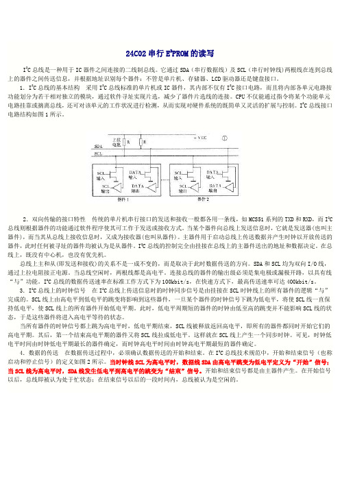
24C02串行E2PROM的读写I2C总线是一种用于IC器件之间连接的二线制总线。
它通过SDA(串行数据线)及SCL(串行时钟线)两根线在连到总线上的器件之间传送信息,并根据地址识别每个器件:不管是单片机、存储器、LCD驱动器还是键盘接口。
1.I2C总线的基本结构采用I2C总线标准的单片机或IC器件,其内部不仅有I2C接口电路,而且将内部各单元电路按功能划分为若干相对独立的模块,通过软件寻址实现片选,减少了器件片选线的连接。
CPU不仅能通过指令将某个功能单元电路挂靠或摘离总线,还可对该单元的工作状况进行检测,从而实现对硬件系统的既简单又灵活的扩展与控制。
I2C总线接口电路结构如图1所示。
2.双向传输的接口特性传统的单片机串行接口的发送和接收一般都各用一条线,如MCS51系列的TXD和RXD,而I2C 总线则根据器件的功能通过软件程序使其可工作于发送或接收方式。
当某个器件向总线上发送信息时,它就是发送器(也叫主器件),而当其从总线上接收信息时,又成为接收器(也叫从器件)。
主器件用于启动总线上传送数据并产生时钟以开放传送的器件,此时任何被寻址的器件均被认为是从器件。
I2C总线的控制完全由挂接在总线上的主器件送出的地址和数据决定。
在总线上,既没有中心机,也没有优先机。
总线上主和从(即发送和接收)的关系不是一成不变的,而是取决于此时数据传送的方向。
SDA和SCL均为双向I/O线,通过上拉电阻接正电源。
当总线空闲时,两根线都是高电平。
连接总线的器件的输出级必须是集电极或漏极开路,以具有线“与”功能。
I2C总线的数据传送速率在标准工作方式下为100kbit/s,在快速方式下,最高传送速率可达400kbit/s。
3.I2C总线上的时钟信号在I2C总线上传送信息时的时钟同步信号是由挂接在SCL时钟线上的所有器件的逻辑“与”完成的。
SCL线上由高电平到低电平的跳变将影响到这些器件,一旦某个器件的时钟信号下跳为低电平,将使SCL线一直保持低电平,使SCL线上的所有器件开始低电平期。
Table 30-1:ADSP-BF60x PVP Register List (Continued)Name DescriptionPVP_PEC_D2TH1PEC Strong Zero Crossing Threshold PVP_IIMn_CFG IIMn ConfigurationPVP_IIMn_CTL IIMn ControlPVP_IIMn_SCALE IIMn Scaling ValuesPVP_IIMn_SOVF_STAT IIMn Signed Overflow StatusPVP_IIMn_UOVF_STAT IIMn Unsigned Overflow StatusPVP_ACU_CFG ACU ConfigurationPVP_ACU_CTL ACU ControlPVP_ACU_OFFSET ACU SUM ConstantPVP_ACU_FACTOR ACU PROD ConstantPVP_ACU_SHIFT ACU Shift ConstantPVP_ACU_MIN ACU Lower Sat Threshold MinPVP_ACU_MAX ACU Upper Sat Threshold MaxPVP_UDS_CFG UDS ConfigurationPVP_UDS_CTL UDS ControlPVP_UDS_OHCNT UDS Output HCNTPVP_UDS_OVCNT UDS Output VCNTPVP_UDS_HAVG UDS HAVGPVP_UDS_VAVG UDS V AVGPVP_IPF0_CFG IPF0 (Camera Pipe) ConfigurationPVP_IPFn_PIPECTL IPFn (Camera/Memory Pipe) Pipe Control PVP_IPFn_CTL IPFn (Camera/Memory Pipe) ControlTable 30-1:ADSP-BF60x PVP Register List (Continued)Name Description PVP_CNVn_C40C41CNVn Coefficients 4,0 and 4,1 PVP_CNVn_C42C43CNVn Coefficients 4,2 and 4,3 PVP_CNVn_C44CNVn Coefficient 4,4PVP_CNVn_SCALE CNVn Scaling FactorPVP_THCn_CFG THCn ConfigurationPVP_THCn_CTL THCn ControlPVP_THCn_HFCNT THCn Histogram Frame Count PVP_THCn_RMAXREP THCn Max RLE ReportsPVP_THCn_CMINVAL THCn Min Clip ValuePVP_THCn_CMINTH THCn Clip Min ThresholdPVP_THCn_CMAXTH THCn Clip Max ThresholdPVP_THCn_CMAXVAL THCn Max Clip ValuePVP_THCn_TH0THCn Threshold Value 0PVP_THCn_TH1THCn Threshold Value 1PVP_THCn_TH2THCn Threshold Value 2PVP_THCn_TH3THCn Threshold Value 3PVP_THCn_TH4THCn Threshold Value 4PVP_THCn_TH5THCn Threshold Value 5PVP_THCn_TH6THCn Threshold Value 6PVP_THCn_TH7THCn Threshold Value 7PVP_THCn_TH8THCn Threshold Value 8PVP_THCn_TH9THCn Threshold Value 9P IPELINED V ISION P ROCESSOR (PVP)PVP F UNCTIONAL D ESCRIPTIONADSP-BF60x PVP Interrupt List PVP_THCn_HCNT7_STATTHCn Histogram Counter Value 7PVP_THCn_HCNT8_STATTHCn Histogram Counter Value 8PVP_THCn_HCNT9_STATTHCn Histogram Counter Value 9PVP_THCn_HCNT10_STATTHCn Histogram Counter Value 10PVP_THCn_HCNT11_STATTHCn Histogram Counter Value 11PVP_THCn_HCNT12_STATTHCn Histogram Counter Value 12PVP_THCn_HCNT13_STAT THCn Histogram Counter Value 13PVP_THCn_HCNT14_STATTHCn Histogram Counter Value 14PVP_THCn_HCNT15_STATTHCn Histogram Counter Value 15PVP_THCn_RREP_STATTHCn Number of RLE Reports PVP_PMA_CFG PMA ConfigurationTable 30-2:ADSP-BF60x PVP Interrupt List Interrupt List Description Interrupt ID DMA Channel Sensitivity PVP0 Camera Pipe DataOut B DMA Channel11138LEVEL PVP0 Camera Pipe DataOut C DMA Channel11239LEVEL PVP0 Camera Pipe StatusOut DMA Channel 11340LEVEL PVP0 Camera Pipe Control In DMA Channel 11441LEVELPVP0 Status 0115LEVEL PVP0 Memory Pipe DataOut DMA Channel 11642LEVELTable 30-1:ADSP-BF60x PVP Register List (Continued)Name Description。
浙江航芯源集成电路科技有限公司浙江航芯源集成电路科技有限公司Zhejiang HangXinYuan IC Technology Co.,LtdC45002 产品手册4通道逻辑门1.产品特性➢额定驱动电流:50mA ➢单芯片集成4通道➢具有输入反相逻辑配置位➢可实现双输入与门、与非门➢每个通道具备2个同相输出2.功能描述C45002是一款采用硅工艺制造的通用逻辑门芯片。
芯片具有4个通道,每个通道均可单独工作。
每个通道都具有输入反相逻辑配置位,使每个通道均可以实现与门或与非门逻辑,还可以配置为缓冲器、反相器。
输入引脚支持2.5V/3.3V/5V 逻辑电平,单个输出最大50mA 电流的驱动能力。
芯片还具备欠压保护功能。
3.典型应用➢缓冲器➢反相器➢电平位移4.裸芯片/封装简介➢本产品为裸芯片,尺寸为840μm*1590μm (含划片槽)有限公司5. 绝对最大额定值使用中超过这些绝对最大值可能对芯片造成永久损坏.6. 主要电参数无特别说明T A = -55℃~125℃,V DD =5V表 1 主要电参数浙江航路科公司7. 功能框图及引脚介绍7.1 功能框图IN1_1IN1_2CH1IN4_1IN4_2CH4IN3_1IN3_2CH3IN2_1IN2_2CH2OUT2_1OUT2_2OUT3_1OUT3_2OUT4_1OUT4_2GND图 1 功能框图268403606图 2 C45002引脚分布➢ 芯片尺寸:840μm×1590 μm (包含划片槽) ➢ PAD 尺寸:100μm×100μm表 2 C45002引脚说明科技有限公司8. 芯片应用说明0V0V 5V图 3 C45002典型应用图1) 4个通道相互独立,共电源共地,每个通道的两个输出为同相,且各个通道功能一致;2) 功率走线如电源、地、输出等,应简短并且具有一定的宽度;3) 多个VDD 和GND 内部已连接,但考虑到性能建议同时使用。
Rev. A2, 26-Feb-01 1 (60)MARC4 – 4-bit Universal MicrocontrollerThe M44C510E is a member of the Atmel Wireless & Microcontrollers' family of 4-bit single-chip microcontrollers.It contains ROM, RAM, up to 34 digital I/O pins, up to 10 maskable external interrupt sources, 4 maskable internal interrupts, a watchdog timer, interval timer, 2 x 8-bit multifunction timer/counter module and a versatile software con-figurable on-chip system clock module.Features / BenefitsD Programmable system clock with prescaler and five different clock sources:– 4-MHz crystal oscillator – 32-kHz crystal oscillator – RC-oscillator fully integrated– RC-oscillator with external resistor adjustment – External clock input D Wide supply voltage range (2.2 V to 6.2 V)D V ery low halt current (< 1 m A)D 4 KByte ROM, 256 x 4-bit RAMD 8 hard– and software interrupt priority levels D Up to 10 external and 4 internal interrupts , bitwise maskable with programmable priority level D Up to 34 I/O lines including 8 high drive I/O-lines (20 mA, V DD = 5 V)D I/O ports – bitwise configurable with combined inter-rupt handling (for serial I/O applications)D 2 x 8-bit multifunction timer/counters D Coded reset and watchdog timer **D Power-on reset and “brown out” function D V arious power-down modesD Efficient, hardware-controlled interrupt handling D High-level programming language in qFORTH D Comprehensive library of useful routines D Windows 95/ NT based development tools(** mask option)13374Figure 1. Block diagramRev. A2, 26-Feb-012 (60)S C L I N B P C 0B P 00B P 12B P 11B P 10O SC I NO S C O U T B P 01B P 02B P 03N R S TV S SV D DB P 43B P 42B P 41B P 40B P B 3B P B 2B P B 1B P B 0B P 70B P 71B P 72B P 73B P 53B P 52B P 51B P 50T I M 1B P A 3B P A 2B P A 1B P A 0T EA V D DB P 61B P 60B PC B P 13V S SB PC 3B PC 2Figure 2. Pin connections SSO44-packageTable 1 Pin description(*) For mask options, please see the order information.Rev. A2, 26-Feb-01 3 (60)Table of Contents1MARC4 Architecture 5. . . . . . . . . . . . . . . . . . . . . . . . . . . . . . . . . . . . . . . . . . . . . . . . . . . . . . . . . . . . . . 1.1General Description 5. . . . . . . . . . . . . . . . . . . . . . . . . . . . . . . . . . . . . . . . . . . . . . . . . . . . . . . . . 1.2Components of MARC4 Core 5. . . . . . . . . . . . . . . . . . . . . . . . . . . . . . . . . . . . . . . . . . . . . . . . .1.2.1ROM 5. . . . . . . . . . . . . . . . . . . . . . . . . . . . . . . . . . . . . . . . . . . . . . . . . . . . . . . . . . . . 1.2.2RAM 6. . . . . . . . . . . . . . . . . . . . . . . . . . . . . . . . . . . . . . . . . . . . . . . . . . . . . . . . . . . . 1.2.3Registers 6. . . . . . . . . . . . . . . . . . . . . . . . . . . . . . . . . . . . . . . . . . . . . . . . . . . . . . . . . 1.2.4ALU 9. . . . . . . . . . . . . . . . . . . . . . . . . . . . . . . . . . . . . . . . . . . . . . . . . . . . . . . . . . . . . 1.2.5Instruction Set 9. . . . . . . . . . . . . . . . . . . . . . . . . . . . . . . . . . . . . . . . . . . . . . . . . . . . . 1.2.6I/O Bus 9. . . . . . . . . . . . . . . . . . . . . . . . . . . . . . . . . . . . . . . . . . . . . . . . . . . . . . . . . .1.3Interrupt Structure 9. . . . . . . . . . . . . . . . . . . . . . . . . . . . . . . . . . . . . . . . . . . . . . . . . . . . . . . . . . .1.3.1Hardware Interrupts 11. . . . . . . . . . . . . . . . . . . . . . . . . . . . . . . . . . . . . . . . . . . . . . . . 1.3.2Software Interrupts 11. . . . . . . . . . . . . . . . . . . . . . . . . . . . . . . . . . . . . . . . . . . . . . . . .1.4Hardware Reset 12. . . . . . . . . . . . . . . . . . . . . . . . . . . . . . . . . . . . . . . . . . . . . . . . . . . . . . . . . . . . . 1.5Clock Generation 13. . . . . . . . . . . . . . . . . . . . . . . . . . . . . . . . . . . . . . . . . . . . . . . . . . . . . . . . . . .1.5.1Clock Module 13. . . . . . . . . . . . . . . . . . . . . . . . . . . . . . . . . . . . . . . . . . . . . . . . . . . . . 1.5.2Oscillator Circuits and External Clock Input Stage 14. . . . . . . . . . . . . . . . . . . . . . . .RC-Oscillator 1 Fully Integrated 14. . . . . . . . . . . . . . . . . . . . . . . . . . . . . . . . . . . . . . External Input Clock 14. . . . . . . . . . . . . . . . . . . . . . . . . . . . . . . . . . . . . . . . . . . . . . . . RC-Oscillator 2 with External Trimming Resistor 14. . . . . . . . . . . . . . . . . . . . . . . . . 4-MHz Oscillator 15. . . . . . . . . . . . . . . . . . . . . . . . . . . . . . . . . . . . . . . . . . . . . . . . . . 32-kHz Oscillator 15. . . . . . . . . . . . . . . . . . . . . . . . . . . . . . . . . . . . . . . . . . . . . . . . . .1.5.3Clock Management Register (CM)15. . . . . . . . . . . . . . . . . . . . . . . . . . . . . . . . . . . . .System Configuration Register (SC)16. . . . . . . . . . . . . . . . . . . . . . . . . . . . . . . . . . .1.5.4Power-down Modes 16. . . . . . . . . . . . . . . . . . . . . . . . . . . . . . . . . . . . . . . . . . . . . . . . . 1.5.5Clock Monitor Mode 17. . . . . . . . . . . . . . . . . . . . . . . . . . . . . . . . . . . . . . . . . . . . . . . .2Peripheral Modules 17. . . . . . . . . . . . . . . . . . . . . . . . . . . . . . . . . . . . . . . . . . . . . . . . . . . . . . . . . . . . . . . 2.1Addressing Peripherals 17. . . . . . . . . . . . . . . . . . . . . . . . . . . . . . . . . . . . . . . . . . . . . . . . . . . . . . . 2.2Bidirectional Ports 20. . . . . . . . . . . . . . . . . . . . . . . . . . . . . . . . . . . . . . . . . . . . . . . . . . . . . . . . . .2.2.1Bidirectional Port 0 and Port 121. . . . . . . . . . . . . . . . . . . . . . . . . . . . . . . . . . . . . . . . 2.2.2Bidirectional Port 5, Port 7 and Port C 22. . . . . . . . . . . . . . . . . . . . . . . . . . . . . . . . . . 2.2.3Bidirectional Port A and Port B with Port Monitor Function 22. . . . . . . . . . . . . . . . 2.2.4Bidirectional Port 624. . . . . . . . . . . . . . . . . . . . . . . . . . . . . . . . . . . . . . . . . . . . . . . . . 2.2.5Bidirectional Port 426. . . . . . . . . . . . . . . . . . . . . . . . . . . . . . . . . . . . . . . . . . . . . . . . . 2.2.6TIM1 – Dedicated Timer 1 I/O Pin 27. . . . . . . . . . . . . . . . . . . . . . . . . . . . . . . . . . . .2.3Interval Timers / Prescaler 27. . . . . . . . . . . . . . . . . . . . . . . . . . . . . . . . . . . . . . . . . . . . . . . . . . . .2.3.1Interval Timer Registers 28. . . . . . . . . . . . . . . . . . . . . . . . . . . . . . . . . . . . . . . . . . . . .2.4Watchdog Timer 29. . . . . . . . . . . . . . . . . . . . . . . . . . . . . . . . . . . . . . . . . . . . . . . . . . . . . . . . . . . . 2.5Timer/Counter Module (TCM)29. . . . . . . . . . . . . . . . . . . . . . . . . . . . . . . . . . . . . . . . . . . . . . . . .2.5.1General Timer/Counter Control Registers 31. . . . . . . . . . . . . . . . . . . . . . . . . . . . . . . 2.5.2Timer/Counter in 16-bit Mode 34. . . . . . . . . . . . . . . . . . . . . . . . . . . . . . . . . . . . . . . . 2.5.3Timer 0 Modes 34. . . . . . . . . . . . . . . . . . . . . . . . . . . . . . . . . . . . . . . . . . . . . . . . . . . . 2.5.4Timer 1 Modes 43. . . . . . . . . . . . . . . . . . . . . . . . . . . . . . . . . . . . . . . . . . . . . . . . . . . .Rev. A2, 26-Feb-014 (60)2.6Buzzer Module 46. . . . . . . . . . . . . . . . . . . . . . . . . . . . . . . . . . . . . . . . . . . . . . . . . . . . . . . . . . . . . 2.7Emulation 48. . . . . . . . . . . . . . . . . . . . . . . . . . . . . . . . . . . . . . . . . . . . . . . . . . . . . . . . . . . . . . . . . 2.8MTP Support 48. . . . . . . . . . . . . . . . . . . . . . . . . . . . . . . . . . . . . . . . . . . . . . . . . . . . . . . . . . . . . . . 2.9Noise Considerations 48. . . . . . . . . . . . . . . . . . . . . . . . . . . . . . . . . . . . . . . . . . . . . . . . . . . . . . . . 2.9.1Noise Immunity 48. . . . . . . . . . . . . . . . . . . . . . . . . . . . . . . . . . . . . . . . . . . . . . . . . . . 2.9.2Electromagnetic Emission 48. . . . . . . . . . . . . . . . . . . . . . . . . . . . . . . . . . . . . . . . . . .3Electrical Characteristics 49. . . . . . . . . . . . . . . . . . . . . . . . . . . . . . . . . . . . . . . . . . . . . . . . . . . . . . . . . . 3.1Absolute Maximum Ratings 49. . . . . . . . . . . . . . . . . . . . . . . . . . . . . . . . . . . . . . . . . . . . . . . . . . . 3.2DC Operating Characteristics 49. . . . . . . . . . . . . . . . . . . . . . . . . . . . . . . . . . . . . . . . . . . . . . . . . . 3.3AC Characteristics 51. . . . . . . . . . . . . . . . . . . . . . . . . . . . . . . . . . . . . . . . . . . . . . . . . . . . . . . . . . 4Pad Layout 56. . . . . . . . . . . . . . . . . . . . . . . . . . . . . . . . . . . . . . . . . . . . . . . . . . . . . . . . . . . . . . . . . . . . . . 5Application Examples 58. . . . . . . . . . . . . . . . . . . . . . . . . . . . . . . . . . . . . . . . . . . . . . . . . . . . . . . . . . . . . . 6Ordering Information 59. . . . . . . . . . . . . . . . . . . . . . . . . . . . . . . . . . . . . . . . . . . . . . . . . . . . . . . . . . . . .Rev. A2, 26-Feb-01 5 (60)1MARC4 Architecture94 8973Figure 3. MARC4 core1.1General Description The MARC4 microcontroller consists of an advanced stack based 4-bit CPU core and on-chip peripherals. The CPU is based on the HARV ARD architecture with physi-cally separate program memory (ROM) and data memory (RAM). Three independent buses, the instruction bus, the memory bus and the I/O bus are used for parallel commu-nication between ROM, RAM and peripherals. This enhances program execution speed by allowing both instruction prefetching, and a simultaneous communica-tion to the on-chip peripheral circuitry. The extremely powerful integrated interrupt controller with associated eight prioritized interrupt levels supports fast and effi-cient processing of hardware events. The MARC4 is designed for the high-level programming language qFORTH. The core includes an expression and a return stack. This architecture allows high-level language pro-gramming without any loss in efficiency or code density.1.2Components of MARC4 CoreThe core contains ROM, RAM, ALU, a program counter,RAM address registers, an instruction decoder and an interrupt controller. The following sections describe each functional block in more detail:1.2.1ROMThe program memory (ROM) is mask programmed with the customer application program during the fabrication of the microcontroller. The ROM is addressed by a 12-bit wide program counter, thus predefining a maximum pro-gram bank size of 4 Kbytes. An additional 1 Kbyte of ROM exists which is used partly for a quality control self-test program. The remaining space is available for the application program. The access to this additional ROM section is done by using a ROM-bank switch.Rev. A2, 26-Feb-016 (60)FFFh7FFh1FFh 000h$AUTOSLEEP$RESETINT0INT1INT2INT3INT4INT5INT6INT796 11517Figure 4. ROM map of M44C510EThe lowest user ROM address segment is taken up by a 512-byte zero page which contains predefined start addresses for interrupt service routines and special sub-routines accessible with single-byte instructions (SCALL). The corresponding memory map is shown in figure 4. Look-up tables of constants can also be held in ROM and are accessed via the MARC4’s built-in TABLE instruction.ROM BankingBank switching is fully supported by the compiler for customers programming with qFORTH. The MARC4switches from one ROM bank to another by writing the new bank number to the ROM Bank Register (RBR).Conventional program space (power-up bank) resides in ROM bank 0. Each ROM bank consists of a 4-KByte ad-dress space whereby the lowest 2 KByte is common to all banks, so that addresses between 000h and 7FFh always accesses the same ROM data (see figure 4). When ROM banking is used, the compiler will, if necessary, insert the program code to save and restore the condition of the RBR on bank switching.1.2.2RAMThe MARC4 contains 256 x 4-bit wide static random access memory (RAM). It is used for the expression stack,the return stack and data memory for variables and arrays.The RAM is addressed by any of the four 8-bit wide RAM address registers SP, RP, X and Y.Expression StackThe 4-bit wide expression stack is addressed with the expression stack pointer (SP). All arithmetic, I/O and memory reference operations take their operands from,and return their result to the expression stack. TheMARC4 performs the operations with the top of stack items (TOS and TOS-1). The TOS register contains the top element of the expression stack and works in the same way as an accumulator. This stack is also used for passing parameters between subroutines and as a scratch pad area for temporary storage of data.Return StackThe 12-bit wide return stack is addressed by the return stack pointer (RP). It is used for storing return addresses of subroutines, interrupt routines and for keeping loop index counts. The return stack can also be used as a temporary storage area.The MARC4 instruction set supports the exchange of data between the top elements of the expression stack and the return stack. The two stacks within the RAM have a user-definable location and maximum depth.1.2.3RegistersThe MARC4 controller has seven programmable regis-ters and one condition code register. They are shown in figure 6.Program Counter (PC)The program counter (PC) is a 12-bit register that contains the address of the next instruction to be fetched from the ROM. Instructions currently being executed are decoded in the instruction decoder to determine the internal micro operations. For linear code (no calls or branches) the pro-gram counter is incremented with every instruction cycle.If a branch, call, return instruction or an interrupt is executed, the program counter is loaded with a new address. The program counter is also used with the TABLE instruction to fetch 8-bit wide ROM constants.Rev. A2, 26-Feb-017 (60)RAMX YR A M a d d r e s s r e g i s t e r :(256 x 4-bit)Global variablesExpression stackReturn stackv 94 8975Figure 5. RAM mapROM Banking Register (RBR)The ROM banking register is a 4-bit register whereby in the M44C510E, only bit 2 is used. This indicates which ROM bank is presently being addressed. The RBR is accessed with a standard qFORTH peripheral read or write instruction (IN or OUT, port address ‘D ’ hex).RAM Address RegistersThe RAM is addressed with the four 8-bit wide RAM address registers: SP, RP, X and Y. These registers allow access to any of the 256 RAM nibbles.Expression Stack Pointer (SP)The stack pointer (SP) contains the address of the next-to-top 4-bit item (TOS-1) of the expression stack. The pointer is automatically preincremented if a nibble is moved onto the stack, or postdecremented if a nibble is removed from the stack. Every postdecrement operation moves the item (TOS-1) to the TOS register before the SP is decremented. After a reset the stack pointer has to be initialized with “ >SP S0 ” to allocate the start address of the expression stack area.Return Stack Pointer (RP)The return stack pointer points to the top element of the 12-bit wide return stack. The pointer automatically pre-increments if an element is moved onto the stack or it postdecrements if an element is removed from the stack.The return stack pointer increments and decrements in steps of 4. This means that every time a 12-bit element is stacked, a 4-bit RAM location is left unwritten. These locations are used by the qFORTH compiler to allocate4-bit variables. After a reset, the return stack pointer has to be initialized with “>RP FCh ”.RAM Address Register ( X and Y )The X and Y registers are used to address any 4-bit item in the RAM. A fetch operation moves the addressed nibble onto the TOS. A store operation moves the TOS to the addressed RAM location. By using either the preincrement or postdecrement, addressing mode arrays in the RAM can be compared, filled or moved.Top Of Stack ( TOS )The top of stack register is the accumulator of the MARC4. All arithmetic/logic, memory reference and I/O operations use this register. The TOS register receives data from the ALU, ROM, RAM or I/O bus.Condition Code Register ( CCR )The 4-bit wide condition code register contains the branch, the carry and the interrupt-enable flag. These bits indicate the current state of the CPU. The CCR flags are set or reset by ALU operations. The instructions SET_BCF, TOG_BF, CCR! and DI allow direct manipulation of the condition code register.Carry/Borrow ( C )The carry/borrow flag indicates that borrow or carry out of arithmetic logic unit ( ALU ) occurred during the last arithmetic operation. During shift and rotate operations,this bit is used as a fifth bit. Boolean operations have no affect on the C flag.Branch ( B )The branch flag controls the conditional program branch-ing. Should the branch flag have been set by a previousRev. A2, 26-Feb-018 (60)instruction, a conditional branch will cause a jump. This flag is affected by arithmetical, logical, shift, and rotate operations.Interrupt Enable ( I )The interrupt-enable flag globally enables or disables the triggering of all interrupt routines with the exception of the non-maskable reset. After a reset, or on executing the DI instruction, the interrupt-enable flag is reset, thus dis-abling all interrupts. The core will not accept any further interrupt requests until the interrupt-enable flag has been set again either by executing an EI, RTI or SLEEP instruc-tion.PCProgram counterReturn stack pointer Expression stack pointerRAM address register (X)RAM address register (Y)Top of stack registerCondition code registerCarry / borrowBranch Interrupt enable ReservedROM bank register 96 11518Figure 6. Programming modelRev. A2, 26-Feb-019 (60)1.2.4ALU94 8977Figure 7. ALU zero-address operationsThe 4-bit ALU performs all the arithmetical, logical, shiftand rotate operations with the top two elements of the ex-pression stack (TOS and TOS-1) and returns the result to the TOS. The ALU operations affect the carry/borrow and branch flag in the condition code register (CCR).1.2.5Instruction SetThe MARC4 instruction set is optimized for the high-level programming language qFORTH. Many MARC4instructions are qFORTH words. This enables the com-piler to generate a fast and compact program code. The CPU has an instruction pipeline which allows the control-ler to prefetch an instruction from ROM at the same time as the present instruction is being executed. The MARC4is a zero-address machine. The instructions contain only the operation to be performed and no source or destination address fields. The operations are implicitly performed on the data placed on the stack. There are one and two byte instructions which are executed within 1 to 4machine cycles. A MARC4 machine cycle is made up of two system clock (SYSCL) cycles. Most of the instruc-tions are only one byte long and are executed in a single machine cycle.1.2.6I/O BusThe I/O ports and the registers of the peripheral modules (Timer 0, Timer 1, Interval timer, Watchdog etc.) are I/Omapped. All communication between the core and the on-chip peripherals takes place via the I/O bus and the associated I/O control. With the MARC4 IN and OUT instructions, the I/O bus enables a direct read or write access to one of the 16 primary I/O addresses. More about the I/O access to the on-chip peripherals is described in the “Peripheral Modules ”. The I/O bus is internal and is not accessible by the customer on the final micro-controller device, but is used as the interface for the MARC4 emulation (see also the section “Emulation ”).1.3Interrupt StructureThe MARC4 can handle interrupts with eight different priority levels. They can be generated from the internal and external interrupt sources or by a software interrupt from the CPU itself. Each interrupt level has a hard-wired priority and an associated vector for the service routine in the ROM (see table 2, page 11). The programmer can postpone the processing of interrupts by resetting the in-terrupt enable flag (I) in the CCR. An interrupt occurrence will still be registered but the interrupt routine is only started after the I flag is set. All interrupts can be masked,and the priority individually software configured by pro-gramming the appropriate control register of the interrupting module (see section “Peripheral Modules ”).Rev. A2, 26-Feb-0110 (60)76543210P r i o r i t y l e v e lTime94 8978Figure 8. Interrupt handlingInterrupt ProcessingFor processing the eight interrupt levels, the MARC4 in-cludes an interrupt controller with two 8-bit wide “interrupt pending ” and “interrupt active ” registers. The interrupt controller samples all interrupt requests during every non-I/O instruction cycle and latches these in the interrupt pending register. Whenever an interrupt request is detected, the CPU interrupts the program currently being executed, on condition that no higher priority interrupt is present in the interrupt active register. If the interrupt-enable bit is set, the processor enters an inter-rupt acknowledge cycle. During this cycle a short call (SCALL) instruction is executed to the service routine and the current PC is saved on the return stack. An inter-rupt service routine is finished with the RTI instruction.This instruction sets the interrupt-enable flag, resets the corresponding bits in the interrupt pending/active register and fetches the return address from the return stack to the program counter. When the interrupt-enable flag is reset (triggering of interrupt routines is disabled), the execution of new interrupt service routines is inhibited,but not the logging of the interrupt requests in the inter-rupt pending register. The execution of the interrupt is then delayed until the interrupt-enable flag is set again.Note that interrupts are only lost if an interrupt request oc-curs while the corresponding bit in the pending register is still set (i.e., the interrupt service routine is not yet fin-ished).It should also be realized that automatic stacking of the RBR is not carried out by the hardware and so if ROM banking is used, the RBR must be stacked on the expres-sion stack by the application program and restored before the RTI. After a master reset (power-on, external or watchdog reset), the interrupt-enable flag and the inter-rupt pending and interrupt active registers are all reset.Interrupt LatencyThe interrupt latency is the time from the occurrence of the interrupt to the interrupt service routine being acti-vated. In the MARC4, this is extremely short and takes between 3 to 5 machine cycles depending on the state of the core.Rev. A2, 26-Feb-0111 (60)Table 2 Interrupt priority table1.3.1Hardware InterruptsTable 3 Hardware interruptsX = hardwired (neither optional or software configurable)# = customer mask option (see “Ordering Information ”)* = software configurable (see “Peripheral Modules ” section for further details)In the M44C510E, there are eleven hardware interrupt sources which can be programmed to occupy a variety of priority levels. With the exception of the reset sources (RST), each source can be individually masked by mask bits in the corresponding control registers. An overview of the possible hardware configurations is shown in table 3.1.3.2Software InterruptsThe program can generate interrupts using the software interrupt instruction (SWI) which is supported in qFORTH by predefined macros named SWI0...SWI7.The software triggered interrupt operates in exactly the same way as any hardware triggered interrupt.The SWI instruction takes the top two elements from the expression stack and writes the corresponding bits via the I/O bus to the interrupt pending register. Thus, by using the SWI instruction, interrupts can be re-prioritized or lower priority processes scheduled for later execution.Rev. A2, 26-Feb-0112 (60)1.4Hardware ResetThe master reset forces the CPU into a well-defined condition, is unmaskable and is activated independent of the current program state. It can be triggered by either initial supply power-up, a short collapse of the power sup-ply, a watchdog time out, activation of the NRST input or the occurrence of a coded reset on Port A (see figure 9).A master reset activation will reset the interrupt enable flag, the interrupt pending registers, the interrupt active registers and initialize all on-chip peripherals.When the reset condition disappears, the CPU remains re-set for a further reset delay time (approx. 80 ms), after which it continues with a short call instruction (opcode C1h) to the ROM address 008h. This activates the initial-ization routine $RESET which in turn initializes all necessary RAM variables, stack pointers and peripheral configuration registers.Power-on ResetThe fully integrated power-on reset circuit ensures that the core is held in a reset state until the minimum operat-ing supply voltage has been reached. A reset condition is also generated should the supply voltage drop momentarily below the minimum operating supply.External Reset (NRST)An external reset can be triggered with the NRST pin. To activate an external reset, the pin should be low for a minimum of 4 m s.Coded Reset (Port A)The coded reset circuit is connected directly to the Port A terminals. By using a mask option, the user can define a hardwired code combination (e.g., all pins low) which, if occurring on the Port A, will generate a reset in the same way as the NRST pin.Table 4 Multiple key reset optionsNote, that if this option is used, the reset is not maskable and will also trigger if the predefined code is written on to the Port A by the CPU itself. Care should also be taken not to generate an unwanted reset by inadvertently pass-ing through the reset code on input transitions. This applies especially if the pins have a high capacitive load.Watchdog ResetThe watchdog ’s function can be enabled via a mask op-tion and triggers a reset with every watchdog counter overflow. To suppress the watchdog reset, the counter must be regularly reset by reading the watchdog timer register address (CWD).The CPU reacts in exactly the same manner as a reset stimulus from any of the above sources.CPU reset16506Figure 9. Reset configurationRev. A2, 26-Feb-0113 (60)1.5Clock Generation1.5.1Clock ModuleThe clock module generates two clocks. The system clock (SYSCL) supplies the CPU and the peripherals while the lower frequency periphery sub-clock (SUBCL)supplies only the peripherals. The modes for clock sources are programmable with the OS1-bit and OS0-bit in the SC-register and the CCS-bit in the CM-register.The clock module includes 4 different internal oscillator types: two RC-oscillators, one 4-MHz crystal oscillator and one 32-kHz crystal oscillator. The pins OSC1 and OSC2 provide the interface to connect a crystal either for the 4-MHz, or the 32-kHz crystal oscillator. SCLIN can be used as an input for an external clock or for connecting an external trimming resistor for the RC-oscillator 2. All necessary components with the exception of the crystal and the trimming resistor are integrated on-chip. Any one of these clock sources can be selected to generate the system clock (SYSCL).In applications that do not require exact timing, it is possible to use the fully integrated RC-oscillator 1without any external components. The RC-oscillator 2 is more stable but the oscillator frequency must be trimmed with an external resistor attached between SCLIN andV DD . In this configuration, for system clock frequencies below 2 MHz,the RC-oscillator 2 frequency can be maintained to within a tolerance of ±10% over the full operating temperature and voltage range.The clock module is programmable via software using the clock management register (CM) and the system configuration register (SC). The required oscillator configuration is selected with the OS[1:0]-bits in the SC-register. A programmable 4-bit divider stage allows the adjustment of the system clock speed. A synchronization stage avoids any clock glitches which could be caused by clock source switching.The CPU always requires SYSCL clocks to execute instructions, process interrupts and enter or leave the SLEEP state. Internal oscillators are, depending on the condition of the NSTOP-bit automatically stopped and started where necessary. Special care must however be taken when using an external clock source which is gated by a one of the microcontroller port signals. This configu-ration can hang up if the external oscillator is switched off while the external clock source is still selected. It is there-fore advisable in such a case to switch first to the internal RC-oscillator 1 source using CSS-bit. The external source can then be reselected later when the external oscillator has again been restarted.Figure 10. Clock module。