Product description
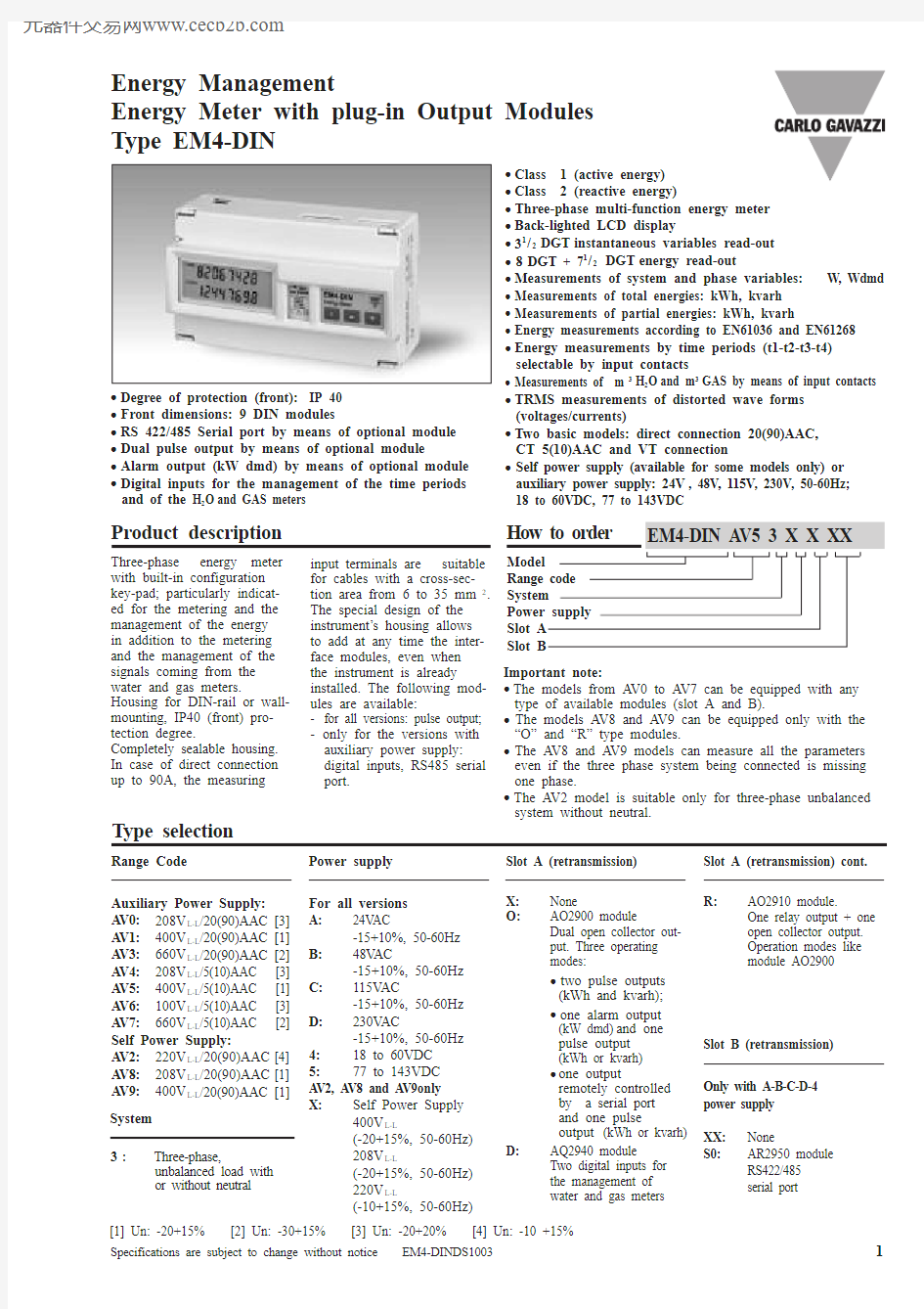
Three-phase energy meter with built-in configuration key-pad; particularly indicat-ed for the metering and the management of the energy in addition to the metering and the management of the signals coming from the water and gas meters.
Housing for DIN-rail or wall-mounting, IP40 (front) pro-tection degree.
Completely sealable housing.In case of direct connection up to 90A, the measuring
input terminals are suitable for cables with a cross-sec-tion area from 6 to 35 mm 2.The special design of the instrument’s housing allows to add at any time the inter-face modules, even when the instrument is already installed. The following mod-ules are available:
-for all versions: pulse output;-only for the versions with auxiliary power supply:digital inputs, RS485 serial port.
Energy Management
Energy Meter with plug-in Output Modules Type EM4-DIN
Type selection
Power supply
For all versions A:24VAC
-15+10%, 50-60Hz
B:48VAC
-15+10%, 50-60Hz
C:115VAC
-15+10%, 50-60Hz
D:230VAC
-15+10%, 50-60Hz
4:18 to 60VDC 5:77 to 143VDC AV2, AV8 and AV9 only X:Self Power Supply
400V L-L
(-20+15%, 50-60Hz)208V L-L
(-20+15%, 50-60Hz)220V L-L
(-10+15%, 50-60Hz)
Range Code
Auxiliary Power Supply:AV0:208V L-L /20(90)AAC [3]AV1:400V L-L /20(90)AAC [1]AV3:660V L-L /20(90)AAC [2]AV4:208V L-L /5(10)AAC [3]AV5:400V L-L /5(10)AAC [1]AV6:100V L-L /5(10)AAC [3]AV7:660V L-L /5(10)AAC [2]Self Power Supply:
AV2:220V L-L /20(90)AAC [4]AV8:208V L-L /20(90)AAC [1]AV9:400V L-L /20(90)AAC [1]Slot A (retransmission)X:None
O:
AO2900 module
Dual open collector out-put. Three operating modes:
?two pulse outputs (kWh and kvarh);?one alarm output (kW dmd)and one pulse output (kWh or kvarh) ?one output
remotely controlled by a serial port and one pulse
output (kWh or kvarh)D:
AQ2940 module Two digital inputs for the management of water and gas meters
Slot A (retransmission) cont.R:
AO2910 module.
One relay output + one open collector output.Operation modes like module AO2900
Slot B (retransmission)Only with A-B-C-D-4 power supply XX:None
S0:
AR2950 module RS422/485
serial port
System 3:
Three-phase,
unbalanced load with or without neutral
[1] Un: -20+15% [2] Un: -30+15% [3] Un: -20+20% [4] Un: -10 +15%
?Class 1 (active energy)?Class 2 (reactive energy)
?Three-phase multi-function energy meter ?Back-lighted LCD display
?31/2DGT instantaneous variables read-out ?8DGT + 71/2DGT energy read-out
?Measurements of system and phase variables: W, Wdmd ?Measurements of total energies: kWh, kvarh ?Measurements of partial energies: kWh, kvarh
?Energy measurements according to EN61036 and EN61268?Energy measurements by time periods (t1-t2-t3-t4)selectable by input contacts
?Measurements of m 3H 2O and m 3GAS by means of input contacts ?TRMS measurements of distorted wave forms (voltages/currents)
?Two basic models: direct connection 20(90)AAC,CT 5(10)AAC and VT connection
?Self power supply (available for some models only) or auxiliary power supply: 24V , 48V , 115V , 230V , 50-60Hz; 18 to 60VDC, 77 to 143VDC
?Degree of protection (front):IP 40?Front dimensions: 9 DIN modules
?RS 422/485 Serial port by means of optional module ?Dual pulse output by means of optional module
?Alarm output (kW dmd) by means of optional module ?Digital inputs for the management of the time periods and of the H 2O and GAS meters
Important note:
?The models from AV0 to AV7 can be equipped with any type of available modules (slot A and B).
?The models AV8 and AV9 can be equipped only with the “O” and “R” type modules.
?The AV8 and AV9 models can measure all the parameters even if the three phase system being connected is missing one phase.
?The AV2 model is suitable only for three-phase unbalanced system without neutral.
EM4-DIN
RS422/RS485 (on request)AR2950 module T ype Multidrop
bidirectional (static and dynamic variables)
Connections
2 or 4 wires, max. distance 1200m, termination directly on the module
Addresses 255, selectable by key-pad Protocol
MODBUS/JBUS
Data (bidirectional)
Dynamic (reading only)
Phase and system variables:see table “Display pages”Static (writing only )
All the programming data, reset of energy, activation of static output.
Stored energy (EEPROM) max. 99.999.999 kWh/kvarh Data format 1 start bit, 8 data bit, no parity,1stop bit Baud-rate 9600 bit/s
Insulation
By means of optocouplers, 2000 V RMS output to measuring inputs
Interface module specifications
Input specifications
EM4-DIN
V OFF 30 VDC max.
Pulse duration
220 ms (ON), ≥220 ms (OFF)According to DIN43864Alarm output
Number of outputs 1
Alarm type
Up alarm, down alarm.Setpoint adjustment
0 to 100% of the electrical scale
Hysteresis 0 to 100% of the electrical scale
On-time delay 0 to 255 seconds Response time 700 ms
Output type Open collector (transistor NPN)V ON 1.2 VDC / max. 100 mA V OFF 30 VDC max.
Insulation
By means of optocouplers, 2000 V RMS outputs to measuring inputs,2000 V RMS output to supply input.
Insulation between the two outputs: functional AO2910 module Relay + open collector output. Working mode like AO2900.
Pulse output One static output+one relay output, other characteristics like AO2900.
Alarm output Only relay output, other characteristics like AO2900.Output type
Static type like module AO2900;
Relay type: SPDT ,
AC1, AC15: 1AAC @250VAC Insulation
2000 V RMS outputs to measuring inputs,2000 V RMS output to
Interface module specifications (cont.)
to 5A)
Display Variables
Up to 4 variables per page Page 1: k Wh-kvarh Page 2a: k Wh (t 1-t 2-t 3-t 4)
k varh (t 1-t 2-t 3-t 4)
Page 2b: GAS m 3day-time tariff,
GAS m 3night tariff
Page 2c: H 2O m 3,GAS m 3Page 3: W L1Page 4: W L2Page 5: W L3Page 6: W dmd
Errors
Phase sequence, serial
communication status, wrong connection of current measuring inputs.
Software functions
EM4-DIN
Variables that can be displayed
Display pages
General Specifications
System variables
Equivalent system voltage
System reactive power
System active power
System apparent power
System power factor
(TPF)
Instantaneous effective voltage
Instantaneous active power
Instantaneous power factor
(TPF)
Instantaneous effective current
Instantaneous apparent power
Instantaneous reactive power
Note:
i = phase (L1, L2 or L3)P = active power Q = reactive power
t 1,t 2=starting and ending time points of consumption recording n = time unit
?t= time interval of consumption recording
n 1,n 2=starting and ending discrete time points of consumption recording
RS422/RS485 “dynamic data”. The variables transmitted are the ones listed in
the table above and those mentioned in the “Display pages” of WM22-DIN data sheet except for: THD A ,THD V ,A max, W dmd max, and VA dmd max.
EM4-DIN
Available models
Possible module combinations
Available modules
EM4-DIN
Wiring diagrams
20(90)A model: three-phase unbalanced load Direct connection (3-phase system)Direct connection (3-phase system + N)5(10)A model:
three-phase unbalanced load Direct connection (3-phase system + N)
Direct connection (3-phase system
with or without neutral)
CT connection (3-phase system with neu tral)
Self-power supply
Fig. 4
5(10)A model: three-phase unbalanced load VT and CT connection (3-phase system)
20(90)A model:
three-phase unbalanced load Auxiliary power supply
Fig. 2Auxiliary power supply
Fig. 1Auxiliary power supply
Fig. 5
Auxiliary power supply
Fig. 6
Auxiliary power supply
Fig. 9
AC power supply
AC power supply
AC power supply
AC power supply
AC power supply
L O A D
L O A D
L O A D
L O A D
L O A D
L O A D
L O A D
CT ARON connection (3-phase system)VT and CT ARON connection (3-phase system)Auxiliary power supply
Fig. 8Auxiliary power supply
Fig. 7
AC power supply
AC power supply
L O A D
L O A D
EM4-DIN
Wiring diagrams (optional modules)
Only open collector outputs: the grounds of the outputs are separated, and therefore it’s possible to carry out, for the same module, two different connections. The load resistance (Rc) must be designed so that the closed contact current is lower than 100mA; the VDC voltage must be lower than or equal to 30V. VDC: power supply voltage output. Vo+: positive output contact (open collector transistor). GND: ground output contact (open collector transistor).
PNP-NPN connections Contact and voltage connection2and 4-wire connection
Digital inputs Fig. 12Digital inputs Fig. 13RS485 Serial output Fig. 14
Accuracy
Accuracy (RDG) depending on the current
Error
10A (Imax)
90A (Imax)
10A (Imax)
90A (Imax)
5A (Ib)
20A (Ib)
5A (Ib)
20A (Ib)
0,5A
2A
1A
4A
0,25A
1A
0.5A
2A
+1%
+4%
-4%
0%
+1.5%
-1%
EN 61036/ IEC 61036 limits (Active energy)
5(10A) Start-up current: 20mA
20(90A) Start-up current: 80mA
-1.5%
Accuracy (RDG) depending on the current
Error
+2%
+4%
-4%
0%
+2.5%
-2%
EN 61268/ IEC 61268 limits (Reactive energy)
5(6A) Start-up current: 20mA
20(90A) Start-up current: 80mA
-2.5%
Relay + open coll. output Fig. 11
10A (Imax)
10A (Imax)
90A (Imax)
90A (Imax)
5A (Ib)
5A (Ib)
20A (Ib)
20A (Ib)
0.25A
0.5A
2A
4A
0.1A
0.25A
1A
2A
sin?=1
sin?=0.5
sin?=1
PF=1
PF=L0.5
or C0.8
EM4-DIN
Terminal boards
Dimensions and panel cut-out
Open collector dual output module
RS485
Serial output module
A O 22900Relay output + open coll. output module
A O 22910A R 2295
0Digital inputs module
A Q 2
2940Keys for:
- values programming;- function selection;
- displaying the measuring pages.2.Display
LCD with alphanumeric indications to:- display configuration parameters;- display all the measured variables.3.Removable label
It shows the following information:- year of manufacturing - serial number
- input voltages and currents - operating frequency - kWh measuring class - kvarh measuring class
- symbols: electric system, attention and dual insulation.4.Hidden dip-switch
Enable/disable the access to the programming procedure.
Front panel description
1.
Key-pad
T o program configuration parameters and to display variables.
S-key to enter programming and confirm selections;
1
2
34